txv00411 02 foxtrot designmanual en
DESCRIPTION
Tecomat PLC mosaic manual that will help you to start designing your program.TRANSCRIPT
TXV00411-EN.doc Created on 3.9.2007 7:26 dop.
Page 1 of 53
Designer's manual for FOXTROT systems.
3rd edition
1. Basic FOXTROT modules.................................................................................................................. 2
1.1. CP-1004 basic module............................................................................................................... 3 1.1.1. Power supply for the CP-1004 basic module ........................................................................ 5 1.1.2. Special functions of the CP-1004 module binary inputs......................................................... 6 1.1.3. Analog inputs of the CP-1004 module ............................................................................... 10 1.1.4. CH1 communication interface of the CP-1004 basic module, RS-232 interface ..................... 12 1.1.5. CH2 communication interface, use of optional submodules................................................. 12 1.1.6. PLC Foxtrot ETHERNET interface (interfaces, cables) ......................................................... 15 1.1.7. TECOMAT Foxtrot PLC connection examples...................................................................... 19 1.1.8. PX-7811, PX-7812 submodules (CH2 Foxtrot fitted with DI and DO) ................................... 21
1.2. CP-1005 basic module............................................................................................................. 23 1.2.1. Analog inputs .................................................................................................................. 24
1.3. CP-1014 basic module............................................................................................................. 27 1.4. CP-1015 basic module............................................................................................................. 27
2. FOXTROT peripheral modules ........................................................................................................ 28 2.1. IB-1301 expansion module...................................................................................................... 29 2.2. IR-1501 expansion module...................................................................................................... 30 2.3. OS-1401 expansion module..................................................................................................... 31 2.4. IT-1601 analog expansion module ........................................................................................... 32 2.5. IT-1602 analog extension module............................................................................................ 35
3. TCL2 bus (peripheral modules connection)...................................................................................... 37 3.1. TCL2 bus installation............................................................................................................... 37 3.2. Connection of expansion modules to the FOXTROT system (TCL2 bus with power supply) .......... 38 3.3. Connection of FOXTROT remote peripheral modules (TCL2 bus without power supply) ............... 40 3.4. Connection of FOXTROT remote peripheral modules and the MASTER module of the CIB bus ..... 41 3.5. Connection of FOXTROT peripheral modules by optical cable (KB-0552 converter)...................... 42
4. CIB bus - bus description ............................................................................................................... 43 4.1. CIB bus properties .................................................................................................................. 43 4.2. BPS2-01M isolation module ..................................................................................................... 43 4.3. BPS2-02M isolation module ..................................................................................................... 44 4.4. MI2-02M external master ........................................................................................................ 45 4.5. CIB bus surge protection......................................................................................................... 46
4.5.1. DTNVEM 1/CIB surge protection ....................................................................................... 46 5. CIB bus – connection examples...................................................................................................... 48
5.1. IM2-20B, 40B, 80B and IM2-140M input units .......................................................................... 48 6. Dimensions, assembly.................................................................................................................... 49
6.1. Dimensions of the CP-10xx basic modules (6-module box):....................................................... 49 6.2. Dimensions of Foxtrot peripheral modules (3-module box):....................................................... 49 6.3. Dimensions of MI2-02M external master (1-module box): ......................................................... 50
7. Technical terms and abbreviations.................................................................................................. 51 8. References.................................................................................................................................... 53
TXV00411-EN.doc Created on 3.9.2007 7:26 dop.
Page 2 of 53
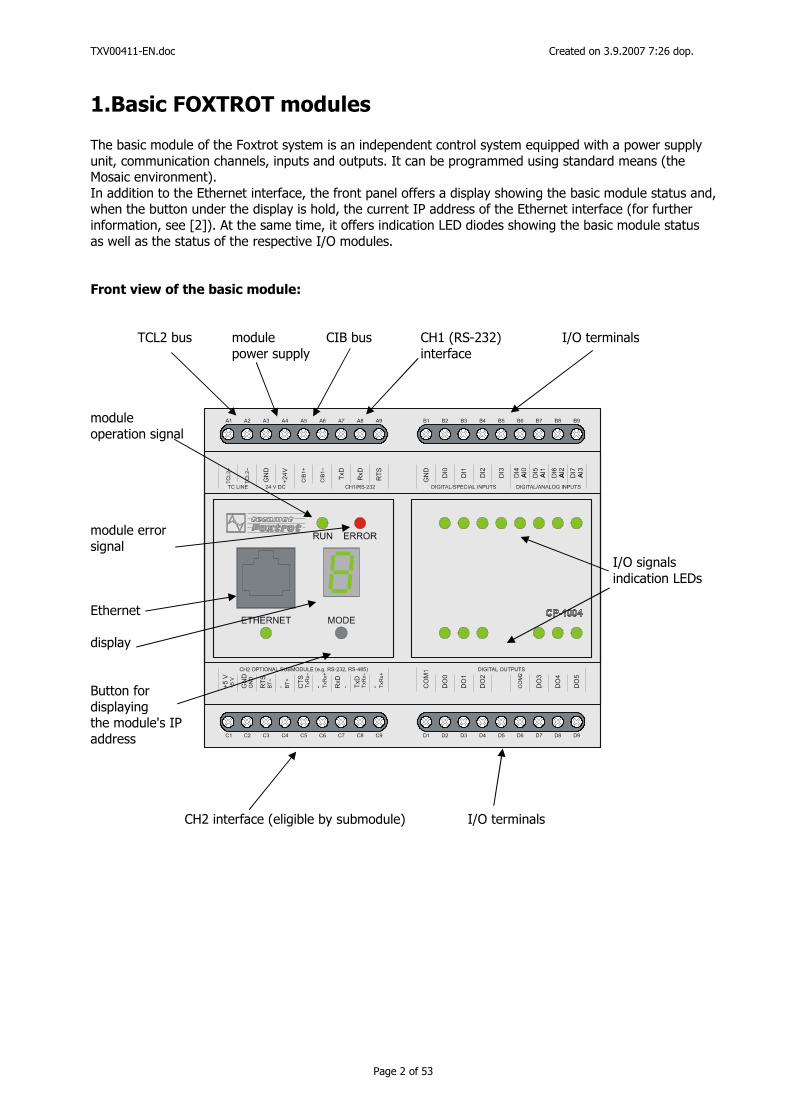
1.Basic FOXTROT modules The basic module of the Foxtrot system is an independent control system equipped with a power supply unit, communication channels, inputs and outputs. It can be programmed using standard means (the Mosaic environment). In addition to the Ethernet interface, the front panel offers a display showing the basic module status and, when the button under the display is hold, the current IP address of the Ethernet interface (for further information, see [2]). At the same time, it offers indication LED diodes showing the basic module status as well as the status of the respective I/O modules. Front view of the basic module:
TCL2 bus module CIB bus CH1 (RS-232) I/O terminals power supply interface
module operation signal module error signal I/O signals
indication LEDs Ethernet display Button for displaying the module's IP address
CH2 interface (eligible by submodule) I/O terminals
TXV00411-EN.doc Created on 3.9.2007 7:26 dop.
Page 3 of 53
1.1.CP-1004 basic module
The CP-1004 basic module is the smallest independent control system of the Foxtrot series. Features: Power supply 24 VDC, max. input power 8W (see chapter 1.1.1) DI0-7 - 8 binary inputs, without galvanic isolation:
DI0 ÷ DI3 optional special functions (see chapter 1.1.2), DI4 ÷ DI7 optional analog inputs 0÷10V (positive input terminal AI0÷AI3)
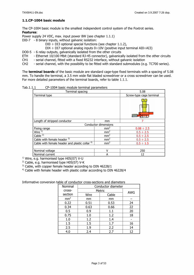
DO0-5 - 6 relay outputs, galvanically isolated from the other circuits ETH - Ethernet 10/100 Mbit (standard RJ-45 connector), galvanically isolated from the other circuits CH1 - serial channel, fitted with a fixed RS232 interface, without galvanic isolation CH2 - serial channel, with the possibility to be fitted with standard submodules (e.g. TC700 series). The terminal boards of the basic module are standard cage-type fixed terminals with a spacing of 5.08 mm. To handle the terminal, a 3.5 mm wide flat bladed screwdriver or a cross screwdriver can be used. For more detailed parameters of the terminal boards, refer to table 1.1.1. Tab.1.1.1 CP-1004 basic module terminal parameters
Terminal spacing 5.08 Terminal type Screw-type cage terminal
Length of stripped conductor mm 7
Conductor dimensions Fixing range mm2 0.08 ÷ 2.5 Wire 1) mm2 0.5 ÷ 2.5 Cable 2) mm2 0.5 ÷ 2.5 Cable with female header 3) mm2 0.5 ÷ 2.5 Cable with female header and plastic collar 4) mm2 0.5 ÷ 1.5
Nominal voltage V 250 Nominal current A 12
1) Wire, e.g. harmonised type H05(07) V-U 2) Cable, e.g. harmonised type H05(07) V-K 3) Cable, with copper female header according to DIN 46228/1 4) Cable with female header with plastic collar according to DIN 46228/4 Informative conversion table of conductor cross-sections and diameters
Conductor diameter Metric
Nominal cross-
section Wire Cable AWG
mm2 mm mm – 0.22 0.51 0.53 24 0.34 0.63 0.66 22 0.5 0.9 1.1 20
0.75 1.0 1.2 18 1.0 1.2 1.4 - 1.5 1.5 1.7 16 2.5 1.9 2.2 14 4.0 2.4 2.7 12
TXV00411-EN.doc Created on 3.9.2007 7:26 dop.
Page 4 of 53
230 V AC
OUTPUT 24 V DC / 2 A
PS
50
/24
U N
+ ++ – ––
L
0 V+24 V
N
PE
230 VAC24 VDC SELV
A1 A2 A3 A4 A5 A6 A7 A8 A9
C1 C2 C3 C4 C5 C6 C7 C8 C9
B1 B2 B3 B4 B5 B6 B7 B8 B9
D1 D2 D3 D4 D5 D6 D7 D8 D9
CP-1004
RUN ERROR
ETHERNET MODE
TC
L2+
TC
L2-
GN
D
+24V
CIB
1+
CIB
1-
TxD
RxD
RT
S
TC LINE 24 V DC CIB LINE CH1/RS-232
CO
M1
DO
0
DO
1
DO
2
CO
M2
DO
3
DO
4
DO
5
DIGITAL OUTPUTSG
ND
DI0
DI1
DI2
DI3
DI4
DIGITAL/SPECIAL INPUTS DIGITAL/ANALOG INPUTS
AI0
DI5
AI1
DI6
AI2
DI7
AI3
+5V
CH2 OPTIONAL SUBMODULE (e.g. RS-232, RS-485)
+5V GN
DG
ND
RT
SB
T- - BT
+
CT
ST
xRx-
- TxR
x+
RxD
- TxD
TxR
x-
- TxR
x+
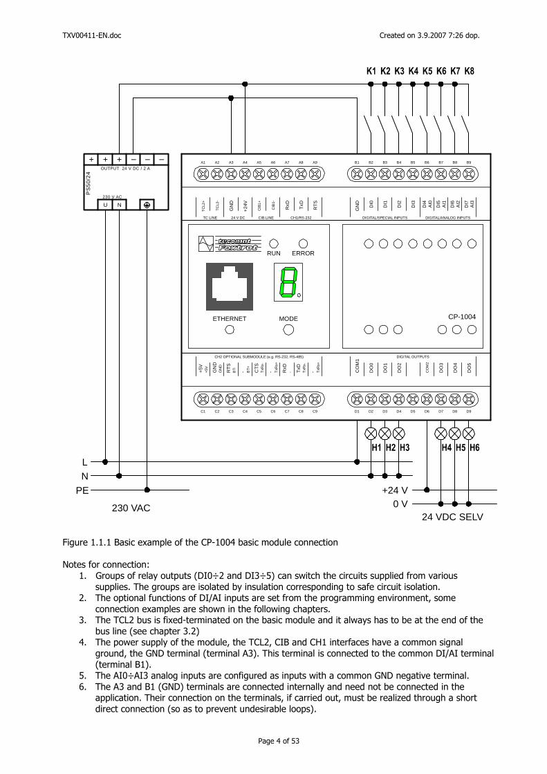
Figure 1.1.1 Basic example of the CP-1004 basic module connection Notes for connection:
1. Groups of relay outputs (DI0÷2 and DI3÷5) can switch the circuits supplied from various supplies. The groups are isolated by insulation corresponding to safe circuit isolation.
2. The optional functions of DI/AI inputs are set from the programming environment, some connection examples are shown in the following chapters.
3. The TCL2 bus is fixed-terminated on the basic module and it always has to be at the end of the bus line (see chapter 3.2)
4. The power supply of the module, the TCL2, CIB and CH1 interfaces have a common signal ground, the GND terminal (terminal A3). This terminal is connected to the common DI/AI terminal (terminal B1).
5. The AI0÷AI3 analog inputs are configured as inputs with a common GND negative terminal. 6. The A3 and B1 (GND) terminals are connected internally and need not be connected in the
application. Their connection on the terminals, if carried out, must be realized through a short direct connection (so as to prevent undesirable loops).

TXV00411-EN.doc Created on 3.9.2007 7:26 dop.
Page 5 of 53
1.1.1. Power supply for the CP-1004 basic module
To function properly, the module requires smoothed direct current supply voltage 24 VDC (in case of power supply backup by batteries, the system can be supplied by a 27.2 VDC supply - we recommend to use the PS2-60/27 or the PS-50/27 power supply unit). The maximum power consumption of the system (under full load - closing of relay inputs, with an additional submodule fitted and with active communication) is 8 W, without the submodule fitted, the maximum power consumption is 3W. The module power supply is galvanically connected with the DI0 ÷ DI7 inputs, the CH1
communication interface, the CIB1 interface and the TCL2 system channel. Furthermore, if the CH2 channel is fitted with a submodule with galvanically non-isolated I/O circuits, these
circuits are galvanically connected with the system power supply.
The common terminal is the GND terminal (terminals A3, terminals B1). CAUTION When applying the system, the common terminal (galvanic connection) of the above-mentioned I/O parts of the module should be taken in account – especially in the case of supplying from multiple positions or multiple power supply sources, or in the case of risk of occurrence of ground loops. SELV: If the power supply unit meets the parameters of SELV power supply units according to ČSN EN 60 950 (ČSN 33 2000-4-41), the SELV requirements are met by all I/O circuits of the system, even in the case that the relay outputs switch low voltage circuits (the insulation of the relay outputs from the internal circuits of the system is 4 kV AC). Power supply unit parameters: Generally, most power supply units with 24V= output stabilised voltage will comply. A non-stabilised power supply unit can also be used, but attention should be paid to the output voltage (for a power supply unit with a high output, the output voltage might exceed the permissible value). Power supply unit output determination: A source with an output of min. 15W is optimal to supply the control system alone. If additional circuits are supplied from the unit, its output has to be increased proportionally. In case a source with a non-stabilised output is used, the permissible range of the supply voltage should be fully observed, especially in cases when power supply units with a high excess output are used. Power supply protection:
The power supply input (terminal A4) is not protected by an internal fuse. We recommend using a front-end external fuse before the module's power supply with a recommended nominal value of T500L250V. Increasing the resistance of the module power supply units: To ensure trouble-free operation even in exceptional situations (lightning strokes, poor general condition of the distribution network or effects of nearby power devices with a negative impact on the distribution network), we recommend using the full range of elements ensuring the resistance of the supply units against unfavourable effects of the environment. For detailed information on the methods of increasing the reliability, see [1], (chapter 2).
TXV00411-EN.doc Created on 3.9.2007 7:26 dop.
Page 6 of 53
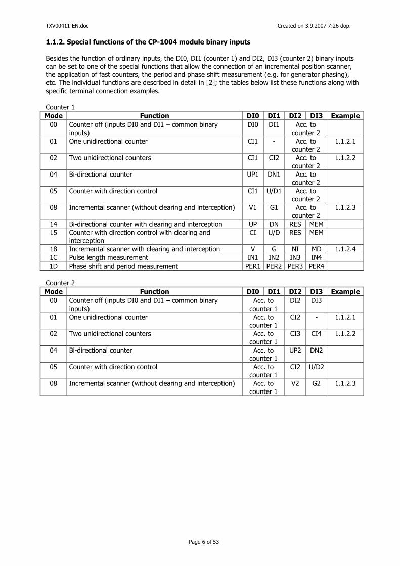
1.1.2. Special functions of the CP-1004 module binary inputs
Besides the function of ordinary inputs, the DI0, DI1 (counter 1) and DI2, DI3 (counter 2) binary inputs can be set to one of the special functions that allow the connection of an incremental position scanner, the application of fast counters, the period and phase shift measurement (e.g. for generator phasing), etc. The individual functions are described in detail in [2]; the tables below list these functions along with specific terminal connection examples. Counter 1 Mode Function DI0 DI1 DI2 DI3 Example
00 Counter off (inputs DI0 and DI1 – common binary inputs)
DI0 DI1 Acc. to counter 2
01 One unidirectional counter CI1 - Acc. to counter 2
1.1.2.1
02 Two unidirectional counters CI1 CI2 Acc. to counter 2
1.1.2.2
04 Bi-directional counter UP1 DN1 Acc. to counter 2
05 Counter with direction control CI1 U/D1 Acc. to counter 2
08 Incremental scanner (without clearing and interception) V1 G1 Acc. to counter 2
1.1.2.3
14 Bi-directional counter with clearing and interception UP DN RES MEM 15 Counter with direction control with clearing and
interception CI U/D RES MEM
18 Incremental scanner with clearing and interception V G NI MD 1.1.2.4 1C Pulse length measurement IN1 IN2 IN3 IN4 1D Phase shift and period measurement PER1 PER2 PER3 PER4
Counter 2 Mode Function DI0 DI1 DI2 DI3 Example
00 Counter off (inputs DI0 and DI1 – common binary inputs)
Acc. to counter 1
DI2 DI3
01 One unidirectional counter Acc. to counter 1
CI2 - 1.1.2.1
02 Two unidirectional counters Acc. to counter 1
CI3 CI4 1.1.2.2
04 Bi-directional counter Acc. to counter 1
UP2 DN2
05 Counter with direction control Acc. to counter 1
CI2 U/D2
08 Incremental scanner (without clearing and interception) Acc. to counter 1
V2 G2 1.1.2.3
TXV00411-EN.doc Created on 3.9.2007 7:26 dop.
Page 7 of 53
B1 B2 B3 B4 B5 B6 B7 B8 B9
GN
D
DI0
DI1
DI2
DI3
DI4
DIGITAL/SPECIAL INPUTS DIGITAL/ANALOG INPUTS
AI0
DI5
AI1
DI6
AI2
DI7
AI3
+24 V
0V
pulzní vstup 1
pulzní vstup 2
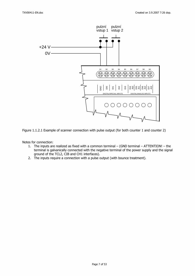
Figure 1.1.2.1 Example of scanner connection with pulse output (for both counter 1 and counter 2) Notes for connection:
1. The inputs are realized as fixed with a common terminal – (GND terminal – ATTENTION! – the terminal is galvanically connected with the negative terminal of the power supply and the signal ground of the TCL2, CIB and CH1 interfaces).
2. The inputs require a connection with a pulse output (with bounce treatment).
TXV00411-EN.doc Created on 3.9.2007 7:26 dop.
Page 8 of 53
B1 B2 B3 B4 B5 B6 B7 B8 B9
GN
D
DI0
DI1
DI2
DI3
DI4
DIGITAL/SPECIAL INPUTS DIGITAL/ANALOG INPUTS
AI0
DI5
AI1
DI6
AI2
DI7
AI3
+24 V
0V
pulzní vstup 1
pulzní vstup 3
pulzní vstup 2
pulzní vstup 4
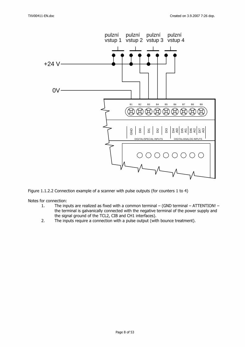
Figure 1.1.2.2 Connection example of a scanner with pulse outputs (for counters 1 to 4) Notes for connection:
1. The inputs are realized as fixed with a common terminal – (GND terminal – ATTENTION! – the terminal is galvanically connected with the negative terminal of the power supply and the signal ground of the TCL2, CIB and CH1 interfaces).
2. The inputs require a connection with a pulse output (with bounce treatment).
TXV00411-EN.doc Created on 3.9.2007 7:26 dop.
Page 9 of 53
B1 B2 B3 B4 B5 B6 B7 B8 B9
GN
D
DI0
DI1
DI2
DI3
DI4
DIGITAL/SPECIAL INPUTS DIGITAL/ANALOG INPUTS
AI0
DI5
AI1
DI6
AI2
DI7
AI3
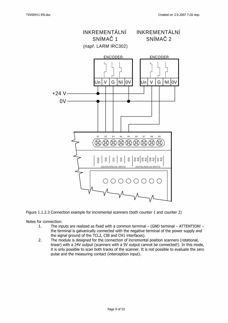
INKREMENTÁLNÍ INKREMENTÁLNÍSNÍMAČ 1 SNÍMAČ 2
(např. LARM IRC302)
ENCODER ENCODER
V VUn Un0V 0VNI NIG G
+24 V
0V
Figure 1.1.2.3 Connection example for incremental scanners (both counter 1 and counter 2) Notes for connection:
1. The inputs are realized as fixed with a common terminal – (GND terminal – ATTENTION! – the terminal is galvanically connected with the negative terminal of the power supply and the signal ground of the TCL2, CIB and CH1 interfaces).
2. The module is designed for the connection of incremental position scanners (rotational, linear) with a 24V output (scanners with a 5V output cannot be connected!). In this mode, it is only possible to scan both tracks of the scanner. It is not possible to evaluate the zero pulse and the measuring contact (interception input).
TXV00411-EN.doc Created on 3.9.2007 7:26 dop.
Page 10 of 53
B1 B2 B3 B4 B5 B6 B7 B8 B9
GN
D
DI0
DI1
DI2
DI3
DI4
DIGITAL/SPECIAL INPUTS DIGITAL/ANALOG INPUTS
AI0
DI5
AI1
DI6
AI2
DI7
AI3
INKREMENTÁLNÍSNÍMAČ 1
(např. LARM IRC302)
Měřicí dotyk snímače 1
ENCODER
VUn 0VNIG
+24 V
0V
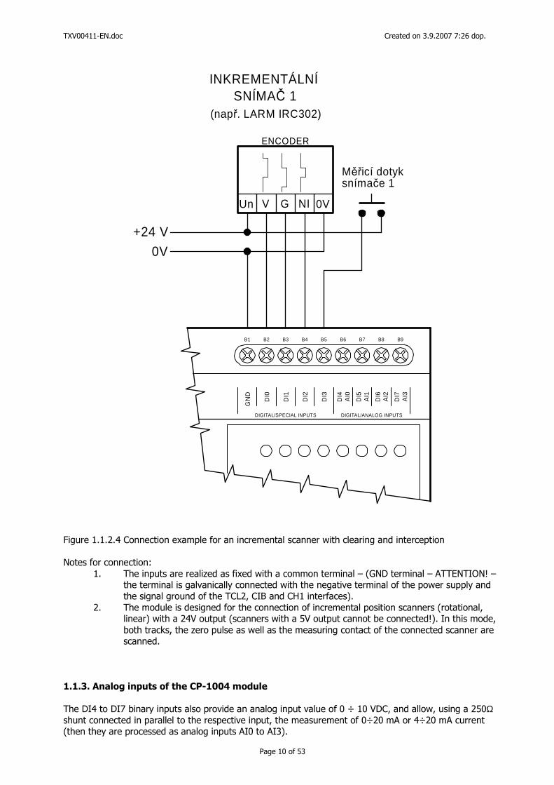
Figure 1.1.2.4 Connection example for an incremental scanner with clearing and interception Notes for connection:
1. The inputs are realized as fixed with a common terminal – (GND terminal – ATTENTION! – the terminal is galvanically connected with the negative terminal of the power supply and the signal ground of the TCL2, CIB and CH1 interfaces).
2. The module is designed for the connection of incremental position scanners (rotational, linear) with a 24V output (scanners with a 5V output cannot be connected!). In this mode, both tracks, the zero pulse as well as the measuring contact of the connected scanner are scanned.
1.1.3. Analog inputs of the CP-1004 module The DI4 to DI7 binary inputs also provide an analog input value of 0 ÷ 10 VDC, and allow, using a 250Ω shunt connected in parallel to the respective input, the measurement of 0÷20 mA or 4÷20 mA current (then they are processed as analog inputs AI0 to AI3).
TXV00411-EN.doc Created on 3.9.2007 7:26 dop.
Page 11 of 53
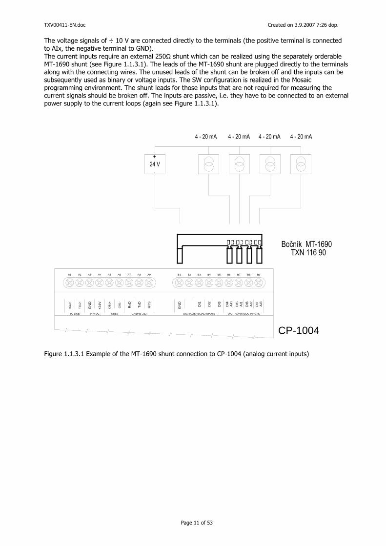
The voltage signals of ÷ 10 V are connected directly to the terminals (the positive terminal is connected to AIx, the negative terminal to GND). The current inputs require an external 250Ω shunt which can be realized using the separately orderable MT-1690 shunt (see Figure 1.1.3.1). The leads of the MT-1690 shunt are plugged directly to the terminals along with the connecting wires. The unused leads of the shunt can be broken off and the inputs can be subsequently used as binary or voltage inputs. The SW configuration is realized in the Mosaic programming environment. The shunt leads for those inputs that are not required for measuring the current signals should be broken off. The inputs are passive, i.e. they have to be connected to an external power supply to the current loops (again see Figure 1.1.3.1).
CP-1004
A1 A2 A3 A4 A5 A6 A7 A8 A9 B1 B2 B3 B4 B5 B6 B7 B8 B9
TC
L2+
TC
L2-
GN
D
+24
V
CIB
1+
CIB
1-
RxD
TxD
RT
S
TC LINE 24 V DC INELS CH1/RS-232
GN
D
DI1
DI2
DI3
DI4
DIGITAL/SPECIAL INPUTS DIGITAL/ANALOG INPUTS
AI0
DI5
AI1
DI6
AI2
DI7
AI3
Figure 1.1.3.1 Example of the MT-1690 shunt connection to CP-1004 (analog current inputs)
TXV00411-EN.doc Created on 3.9.2007 7:26 dop.
Page 12 of 53
1.1.4. CH1 communication interface of the CP-1004 basic module, RS-232 interface
The CP-1004 basic module is fitted with asynchronous serial channels (CH1, CH2), the CIB1 interface, the TCL2 system channel and the ETHERNET interface. Each serial channel as well as the logic data channel LCH (one Ethernet interface can realize up to four LCHs) can be set to one of the communication modes and realize various networks and interconnections. Any of the channels in the PC mode can be used for PLC programming, but always one at a time! The serial interface of the CH1 central unit is fitted with a fixed terminal board. A view of the terminal board (with the standard working position of the PLC on the switchgear panel) is given in Figure 1.1.4.1.
A1 A2 A3 A4 A5 A6 A7 A8 A9
TxD
RxD
RT
S
CH1/RS-232
GN
D
24 V DC
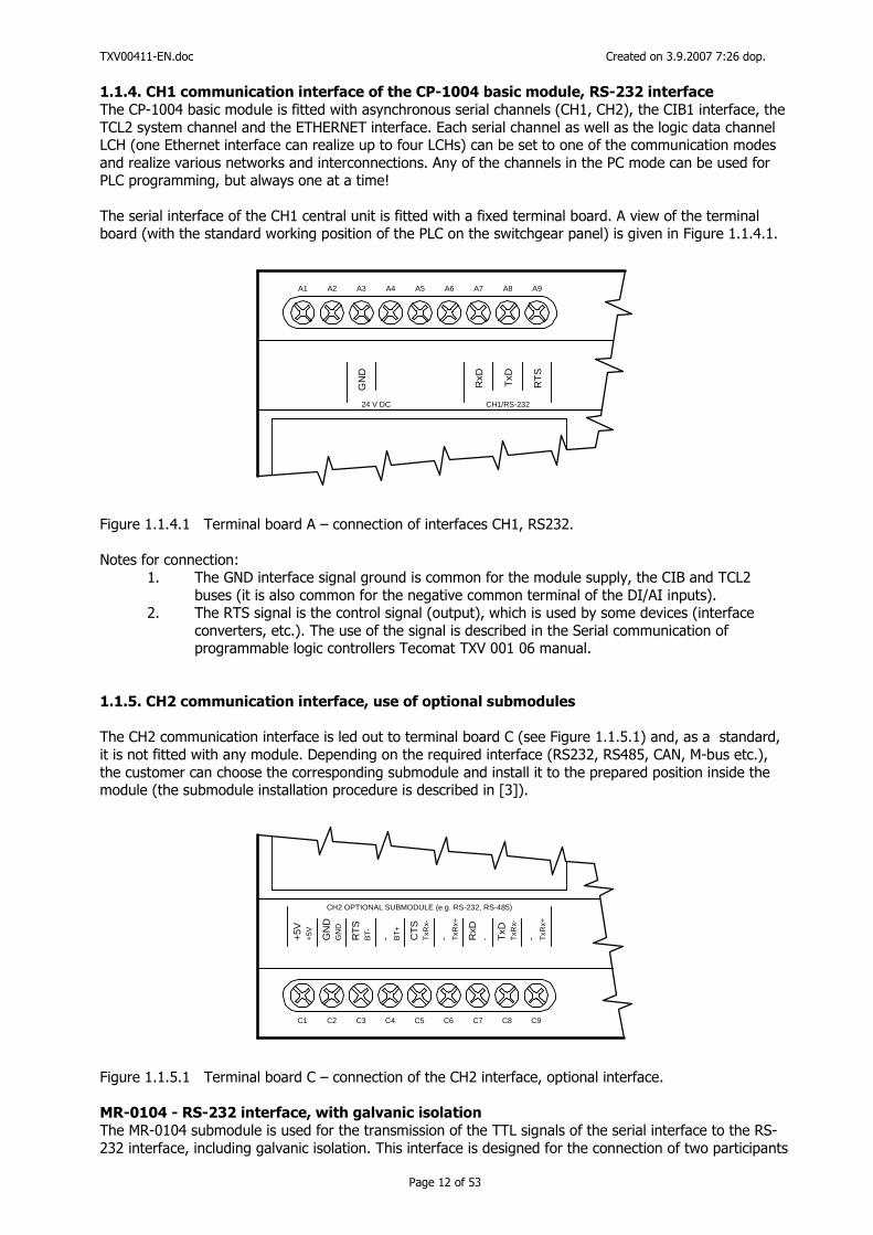
Figure 1.1.4.1 Terminal board A – connection of interfaces CH1, RS232. Notes for connection:
1. The GND interface signal ground is common for the module supply, the CIB and TCL2 buses (it is also common for the negative common terminal of the DI/AI inputs).
2. The RTS signal is the control signal (output), which is used by some devices (interface converters, etc.). The use of the signal is described in the Serial communication of programmable logic controllers Tecomat TXV 001 06 manual.
1.1.5. CH2 communication interface, use of optional submodules
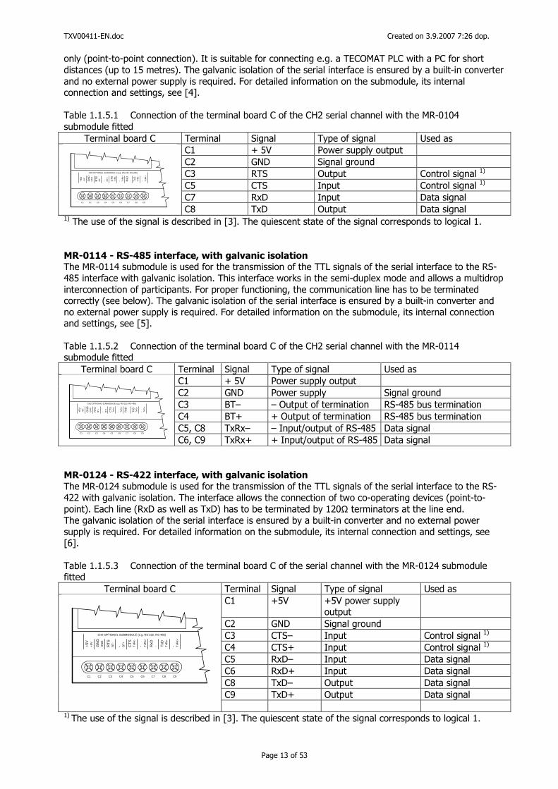
The CH2 communication interface is led out to terminal board C (see Figure 1.1.5.1) and, as a standard, it is not fitted with any module. Depending on the required interface (RS232, RS485, CAN, M-bus etc.), the customer can choose the corresponding submodule and install it to the prepared position inside the module (the submodule installation procedure is described in [3]).
C1 C2 C3 C4 C5 C6 C7 C8 C9
+5V
CH2 OPTIONAL SUBMODULE (e.g. RS-232, RS-485)
+5V
GN
DG
ND
RT
SB
T- - BT
+
CT
ST
xRx-
- TxR
x+
RxD
- TxD
TxR
x-
- TxR
x+
Figure 1.1.5.1 Terminal board C – connection of the CH2 interface, optional interface. MR-0104 - RS-232 interface, with galvanic isolation
The MR-0104 submodule is used for the transmission of the TTL signals of the serial interface to the RS-232 interface, including galvanic isolation. This interface is designed for the connection of two participants
TXV00411-EN.doc Created on 3.9.2007 7:26 dop.
Page 13 of 53
only (point-to-point connection). It is suitable for connecting e.g. a TECOMAT PLC with a PC for short distances (up to 15 metres). The galvanic isolation of the serial interface is ensured by a built-in converter and no external power supply is required. For detailed information on the submodule, its internal connection and settings, see [4]. Table 1.1.5.1 Connection of the terminal board C of the CH2 serial channel with the MR-0104 submodule fitted
Terminal board C Terminal Signal Type of signal Used as C1 + 5V Power supply output C2 GND Signal ground C3 RTS Output Control signal 1)
C5 CTS Input Control signal 1)
C7 RxD Input Data signal C1 C2 C3 C4 C5 C6 C7 C8 C9
+5V
CH2 OPTIONAL SUBMODULE (e.g. RS-232, RS-485)
+5V
GN
DG
ND
RT
SB
T- - BT
+
CT
ST
xRx-
- TxR
x+
RxD
- TxD
TxR
x-
- TxR
x+
C8 TxD Output Data signal 1) The use of the signal is described in [3]. The quiescent state of the signal corresponds to logical 1. MR-0114 - RS-485 interface, with galvanic isolation The MR-0114 submodule is used for the transmission of the TTL signals of the serial interface to the RS-485 interface with galvanic isolation. This interface works in the semi-duplex mode and allows a multidrop interconnection of participants. For proper functioning, the communication line has to be terminated correctly (see below). The galvanic isolation of the serial interface is ensured by a built-in converter and no external power supply is required. For detailed information on the submodule, its internal connection and settings, see [5]. Table 1.1.5.2 Connection of the terminal board C of the CH2 serial channel with the MR-0114 submodule fitted
Terminal board C Terminal Signal Type of signal Used as C1 + 5V Power supply output C2 GND Power supply Signal ground C3 BT– – Output of termination RS-485 bus termination C4 BT+ + Output of termination RS-485 bus termination C5, C8 TxRx– – Input/output of RS-485 Data signal
C1 C2 C3 C4 C5 C6 C7 C8 C9
+5V
CH2 OPTIONAL SUBMODULE (e.g. RS-232, RS-485)
+5V
GN
DG
ND
RT
SB
T- - BT
+
CT
ST
xRx-
- TxR
x+
RxD
- TxD
TxR
x-
- TxR
x+
C6, C9 TxRx+ + Input/output of RS-485 Data signal MR-0124 - RS-422 interface, with galvanic isolation
The MR-0124 submodule is used for the transmission of the TTL signals of the serial interface to the RS-422 with galvanic isolation. The interface allows the connection of two co-operating devices (point-to-point). Each line (RxD as well as TxD) has to be terminated by 120Ω terminators at the line end. The galvanic isolation of the serial interface is ensured by a built-in converter and no external power supply is required. For detailed information on the submodule, its internal connection and settings, see [6]. Table 1.1.5.3 Connection of the terminal board C of the serial channel with the MR-0124 submodule fitted
Terminal board C Terminal Signal Type of signal Used as C1 +5V +5V power supply
output
C2 GND Signal ground C3 CTS– Input Control signal 1)
C4 CTS+ Input Control signal 1)
C5 RxD– Input Data signal C6 RxD+ Input Data signal C8 TxD– Output Data signal C9 TxD+ Output Data signal
C1 C2 C3 C4 C5 C6 C7 C8 C9
+5V
CH2 OPTIONAL SUBMODULE (e.g. RS-232, RS-485)
+5V GN
DG
ND
RT
SB
T- - BT
+
CT
ST
xRx-
- TxR
x+
RxD
- TxD
TxR
x-
- TxR
x+
1) The use of the signal is described in [3]. The quiescent state of the signal corresponds to logical 1.
TXV00411-EN.doc Created on 3.9.2007 7:26 dop.
Page 14 of 53
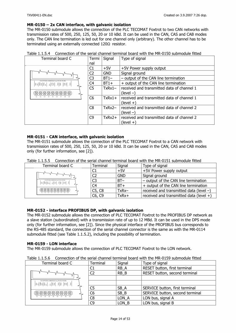
MR-0150 – 2x CAN interface, with galvanic isolation
The MR-0150 submodule allows the connection of the PLC TECOMAT Foxtrot to two CAN networks with transmission rates of 500, 250, 125, 50, 20 or 10 kBd. It can be used in the CAN, CAS and CAB modes only. The CAN line termination is led out for one channel only (arbitrary). The other channel has to be terminated using an externally connected 120Ω resistor. Table 1.1.5.4 Connection of the serial channel terminal board with the MR-0150 submodule fitted
Terminal board C Terminal
Signal Type of signal
C1 +5V +5V Power supply output C2 GND Signal ground C3 BT1– – output of the CAN line termination C4 BT1+ + output of the CAN line termination C5 TxRx1– received and transmitted data of channel 1
(level –) C6 TxRx1+ received and transmitted data of channel 1
(level +) C8 TxRx2– received and transmitted data of channel 2
(level –)
C1 C2 C3 C4 C5 C6 C7 C8 C9
+5
V
CH2 OPTIONAL SUBMODULE (e.g. RS-232, RS-485)
+5V
GN
DG
ND
RT
SB
T- - BT
+
CT
ST
xRx-
- TxR
x+
RxD
- TxD
TxR
x-
- TxR
x+
C9 TxRx2+ received and transmitted data of channel 2 (level +)
MR-0151 - CAN interface, with galvanic isolation The MR-0151 submodule allows the connection of the PLC TECOMAT Foxtrot to a CAN network with transmission rates of 500, 250, 125, 50, 20 or 10 kBd. It can be used in the CAN, CAS and CAB modes only (for further information, see [2]). Table 1.1.5.5 Connection of the serial channel terminal board with the MR-0151 submodule fitted
Terminal board C Terminal Signal Type of signal C1 +5V +5V Power supply output C2 GND Signal ground C3 BT– – output of the CAN line termination C4 BT+ + output of the CAN line termination C5, C8 TxRx– received and transmitted data (level –)
C1 C2 C3 C4 C5 C6 C7 C8 C9
+5V
CH2 OPTIONAL SUBMODULE (e.g. RS-232, RS-485)
+5V
GN
DG
ND
RT
SB
T- - BT
+
CT
ST
xRx-
- TxR
x+
RxD
- TxD
TxR
x-
- TxR
x+
C6, C9 TxRx+ received and transmitted data (level +) MR-0152 - interface PROFIBUS DP, with galvanic isolation The MR-0152 submodule allows the connection of PLC TECOMAT Foxtrot to the PROFIBUS DP network as a slave station (subordinated) with a transmission rate of up to 12 MBd. It can be used in the DPS mode only (for further information, see [2]). Since the physical interface of the PROFIBUS bus corresponds to the RS-485 standard, the connection of the serial channel connector is the same as with the MR-0114 submodule fitted (see Table 1.1.5.2), including the possibility of termination. MR-0159 - LON interface
The MR-0159 submodule allows the connection of PLC TECOMAT Foxtrot to the LON network. Table 1.1.5.6 Connection of the serial channel terminal board with the MR-0159 submodule fitted
Terminal board C Terminal Signal Type of signal C1 RB_A RESET button, first terminal C2 RB_B RESET button, second terminal C5 SB_A SERVICE button, first terminal C6 SB_B SERVICE button, second terminal C8 LON_A LON bus, signal A C1 C2 C3 C4 C5 C6 C7 C8 C9
+5
V
CH2 OPTIONAL SUBMODULE (e.g. RS-232, RS-485)
+5V
GN
DG
ND
RT
SB
T- - BT
+
CT
ST
xRx-
- TxR
x+
RxD
- TxD
TxR
x-
- TxR
x+
C9 LON_B LON bus, signal B
TXV00411-EN.doc Created on 3.9.2007 7:26 dop.
Page 15 of 53
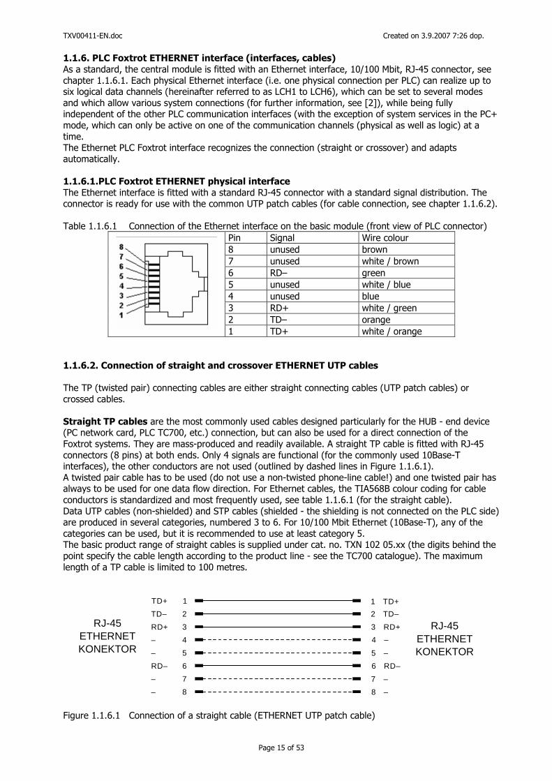
1.1.6. PLC Foxtrot ETHERNET interface (interfaces, cables)
As a standard, the central module is fitted with an Ethernet interface, 10/100 Mbit, RJ-45 connector, see chapter 1.1.6.1. Each physical Ethernet interface (i.e. one physical connection per PLC) can realize up to six logical data channels (hereinafter referred to as LCH1 to LCH6), which can be set to several modes and which allow various system connections (for further information, see [2]), while being fully independent of the other PLC communication interfaces (with the exception of system services in the PC+ mode, which can only be active on one of the communication channels (physical as well as logic) at a time. The Ethernet PLC Foxtrot interface recognizes the connection (straight or crossover) and adapts automatically. 1.1.6.1.PLC Foxtrot ETHERNET physical interface
The Ethernet interface is fitted with a standard RJ-45 connector with a standard signal distribution. The connector is ready for use with the common UTP patch cables (for cable connection, see chapter 1.1.6.2). Table 1.1.6.1 Connection of the Ethernet interface on the basic module (front view of PLC connector)
Pin Signal Wire colour 8 unused brown 7 unused white / brown 6 RD– green 5 unused white / blue 4 unused blue 3 RD+ white / green 2 TD– orange
1 TD+ white / orange 1.1.6.2. Connection of straight and crossover ETHERNET UTP cables
The TP (twisted pair) connecting cables are either straight connecting cables (UTP patch cables) or crossed cables. Straight TP cables are the most commonly used cables designed particularly for the HUB - end device (PC network card, PLC TC700, etc.) connection, but can also be used for a direct connection of the Foxtrot systems. They are mass-produced and readily available. A straight TP cable is fitted with RJ-45 connectors (8 pins) at both ends. Only 4 signals are functional (for the commonly used 10Base-T interfaces), the other conductors are not used (outlined by dashed lines in Figure 1.1.6.1). A twisted pair cable has to be used (do not use a non-twisted phone-line cable!) and one twisted pair has always to be used for one data flow direction. For Ethernet cables, the TIA568B colour coding for cable conductors is standardized and most frequently used, see table 1.1.6.1 (for the straight cable). Data UTP cables (non-shielded) and STP cables (shielded - the shielding is not connected on the PLC side) are produced in several categories, numbered 3 to 6. For 10/100 Mbit Ethernet (10Base-T), any of the categories can be used, but it is recommended to use at least category 5. The basic product range of straight cables is supplied under cat. no. TXN 102 05.xx (the digits behind the point specify the cable length according to the product line - see the TC700 catalogue). The maximum length of a TP cable is limited to 100 metres.
TD+ 1 1 TD+
TD– 2 2 TD–RJ-45 RJ-45
KONEKTOR KONEKTOR
ETHERNET ETHERNETRD+ 3
RD– 6
3 RD+
6 RD–
– 4
– 7
– 5
– 8
4 –
7 –
5 –
8 –
Figure 1.1.6.1 Connection of a straight cable (ETHERNET UTP patch cable)
TXV00411-EN.doc Created on 3.9.2007 7:26 dop.
Page 16 of 53
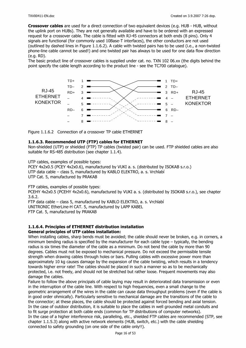
Crossover cables are used for a direct connection of two equivalent devices (e.g. HUB - HUB, without the uplink port on HUBs). They are not generally available and have to be ordered with an expressed request for a crossover cable. The cable is fitted with RJ-45 connectors at both ends (8 pins). Only 4 signals are functional (for commonly used 10Base-T interfaces), the other conductors are not used (outlined by dashed lines in Figure 1.1.6.2). A cable with twisted pairs has to be used (i.e., a non-twisted phone-line cable cannot be used!) and one twisted pair has always to be used for one data flow direction (e.g. RD). The basic product line of crossover cables is supplied under cat. no. TXN 102 06.xx (the digits behind the point specify the cable length according to the product line - see the TC700 catalogue).
TD+ 1 1 TD+
TD– 2 2 TD–RJ-45 RJ-45
KONEKTOR KONEKTOR
ETHERNET ETHERNETRD+ 3
RD– 6
3 RD+
6 RD–
– 4
– 7
– 5
– 8
4 –
7 –
5 –
8 –
Figure 1.1.6.2 Connection of a crossover TP cable ETHERNET 1.1.6.3. Recommended UTP (FTP) cables for ETHERNET
Non-shielded (UTP) or shielded (FTP) TP cables (twisted pair) can be used. FTP shielded cables are also suitable for RS-485 distribution (see chapter 1.1.4). UTP cables, examples of possible types: PCEY 4x2x0.5 (PCEY 4x2x0.6), manufactured by VUKI a. s. (distributed by ISOKAB s.r.o.) UTP data cable – class 5, manufactured by KABLO ELEKTRO, a. s. Vrchlabí UTP Cat. 5, manufactured by PRAKAB FTP cables, examples of possible types: PCEHY 4x2x0.5 (PCEHY 4x2x0.6), manufactured by VUKI a. s. (distributed by ISOKAB s.r.o.), see chapter 3.6.2. FTP data cable – class 5, manufactured by KABLO ELEKTRO, a. s. Vrchlabí UNITRONIC EtherLine-H CAT. 5, manufactured by LAPP KABEL FTP Cat. 5, manufactured by PRAKAB 1.1.6.4. Principles of ETHERNET distribution installation General principles of UTP cables installation:
When installing cables, sharp bends must be avoided; the cable should never be broken, e.g. in corners, a minimum bending radius is specified by the manufacturer for each cable type – typically, the bending radius is six times the diameter of the cable as a minimum. Do not bend the cable by more than 90 degrees. Cables must not be exposed to mechanical pressure. Do not exceed the permissible tensile strength when drawing cables through holes or bars. Pulling cables with excessive power more than approximately 10 kg causes damage by the expansion of the cable twisting, which results in a tendency towards higher error rate! The cables should be placed in such a manner so as to be mechanically protected, i.e. not freely, and should not be stretched but rather loose. Frequent movements may also damage the cables. Failure to follow the above principals of cable laying may result in deteriorated data transmission or even in the interruption of the cable line. With respect to high frequencies, even a small change to the geometric arrangement of the wires in the cable can cause data throughput problems (even if the cable is in good order ohmically). Particularly sensitive to mechanical damage are the transitions of the cable to the connector; at these places, the cable should be protected against forced bending and axial tension. In the case of outdoor distribution, it is suitable to place the cables in well grounded metal conduits and to fit surge protection at both cable ends (common for TP distributions of computer networks). In the case of a higher interference risk, paralleling, etc., shielded FTP cables are recommended (STP, see chapter 1.1.5.3) along with active network elements (HUB, switch, etc.) with the cable shielding connected to safety grounding (on one side of the cable only!!).
TXV00411-EN.doc Created on 3.9.2007 7:26 dop.
Page 17 of 53
Paralleling with other cables:
It is not permissible to lay UTP cables close to power lines. If the minimum distance (0.15 m) cannot be complied with, especially when the distribution is done in bars and plastic conduits, shielding channels have to be used for computer distribution lines (conduits made of zinc-coated sheet metal). These conduits have to be well conductively connected throughout the whole distribution system and have to be connected with the ground conductor of the power lines. The UTP cables have to be in a sufficient distance (50 mm) from any part of the low voltage circuits (230 VAC). 1.1.6.5. Examples of ETHERNET networks connection
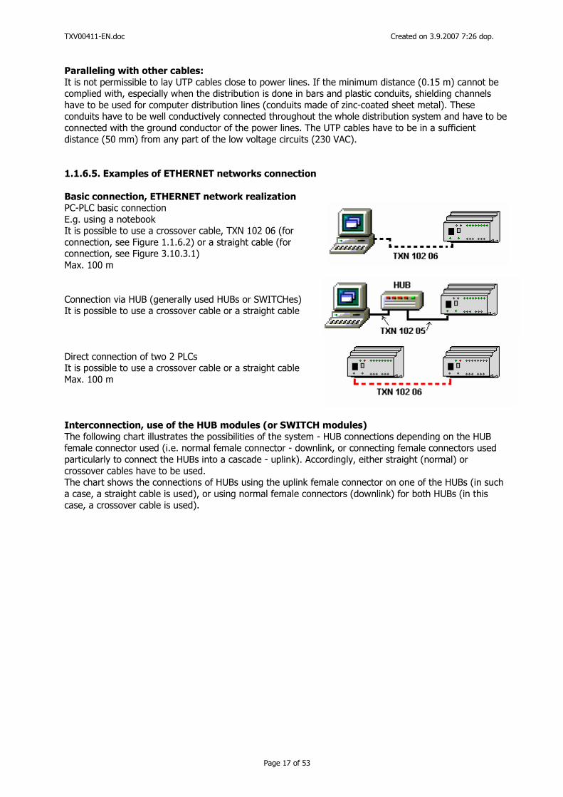
Basic connection, ETHERNET network realization PC-PLC basic connection E.g. using a notebook It is possible to use a crossover cable, TXN 102 06 (for connection, see Figure 1.1.6.2) or a straight cable (for connection, see Figure 3.10.3.1) Max. 100 m Connection via HUB (generally used HUBs or SWITCHes) It is possible to use a crossover cable or a straight cable Direct connection of two 2 PLCs It is possible to use a crossover cable or a straight cable Max. 100 m Interconnection, use of the HUB modules (or SWITCH modules)
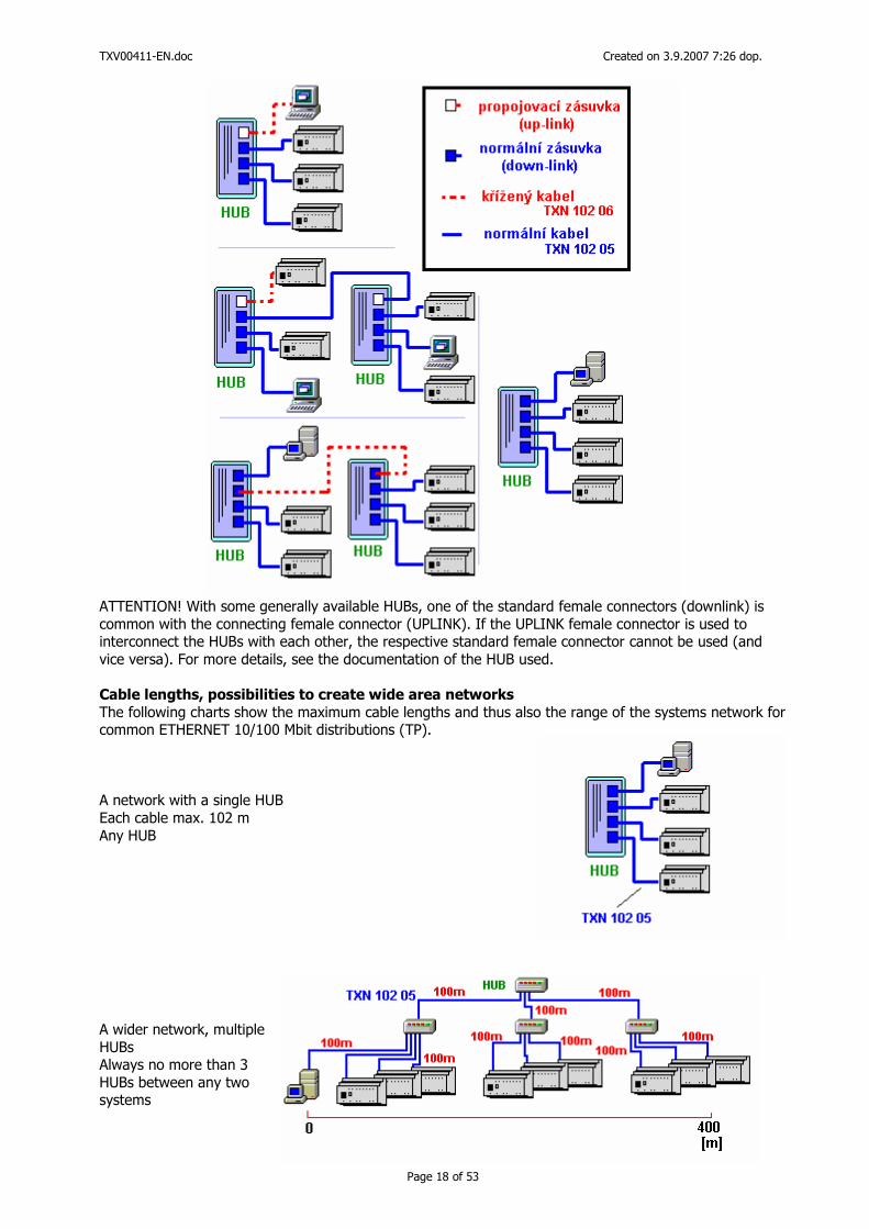
The following chart illustrates the possibilities of the system - HUB connections depending on the HUB female connector used (i.e. normal female connector - downlink, or connecting female connectors used particularly to connect the HUBs into a cascade - uplink). Accordingly, either straight (normal) or crossover cables have to be used. The chart shows the connections of HUBs using the uplink female connector on one of the HUBs (in such a case, a straight cable is used), or using normal female connectors (downlink) for both HUBs (in this case, a crossover cable is used).
TXV00411-EN.doc Created on 3.9.2007 7:26 dop.
Page 18 of 53
ATTENTION! With some generally available HUBs, one of the standard female connectors (downlink) is common with the connecting female connector (UPLINK). If the UPLINK female connector is used to interconnect the HUBs with each other, the respective standard female connector cannot be used (and vice versa). For more details, see the documentation of the HUB used. Cable lengths, possibilities to create wide area networks
The following charts show the maximum cable lengths and thus also the range of the systems network for common ETHERNET 10/100 Mbit distributions (TP). A network with a single HUB Each cable max. 102 m Any HUB A wider network, multiple HUBs Always no more than 3 HUBs between any two systems
TXV00411-EN.doc Created on 3.9.2007 7:26 dop.
Page 19 of 53
1.1.7. TECOMAT Foxtrot PLC connection examples
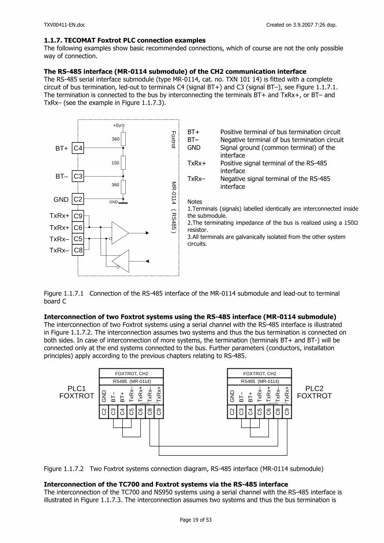
The following examples show basic recommended connections, which of course are not the only possible way of connection. The RS-485 interface (MR-0114 submodule) of the CH2 communication interface The RS-485 serial interface submodule (type MR-0114, cat. no. TXN 101 14) is fitted with a complete circuit of bus termination, led-out to terminals C4 (signal BT+) and C3 (signal BT–), see Figure 1.1.7.1. The termination is connected to the bus by interconnecting the terminals BT+ and TxRx+, or BT– and TxRx– (see the example in Figure 1.1.7.3).
C6
C5
TxRx– C8
TxRx–
C2GND
C4BT+
C3BT–
C9
TxRx+
TxRx+F
oxtrotM
R-0114 ( R
S485 )
360
150
360
+5V
GND
Figure 1.1.7.1 Connection of the RS-485 interface of the MR-0114 submodule and lead-out to terminal board C Interconnection of two Foxtrot systems using the RS-485 interface (MR-0114 submodule)
The interconnection of two Foxtrot systems using a serial channel with the RS-485 interface is illustrated in Figure 1.1.7.2. The interconnection assumes two systems and thus the bus termination is connected on both sides. In case of interconnection of more systems, the termination (terminals BT+ and BT-) will be connected only at the end systems connected to the bus. Further parameters (conductors, installation principles) apply according to the previous chapters relating to RS-485.
PLC1FOXTROT
PLC2FOXTROT
C5
T
xRx–
C8
T
xRx–
C2
G
ND
C4
B
T+
C3
B
T–
C6
T
xRx+
C9
T
xRx+
FOXTROT, CH2
RS485 (MR-0114)
C5
T
xRx–
C8
T
xRx–
C2
G
ND
C4
B
T+
C3
B
T–
C6
T
xRx+
C9
T
xRx+
FOXTROT, CH2
RS485 (MR-0114)
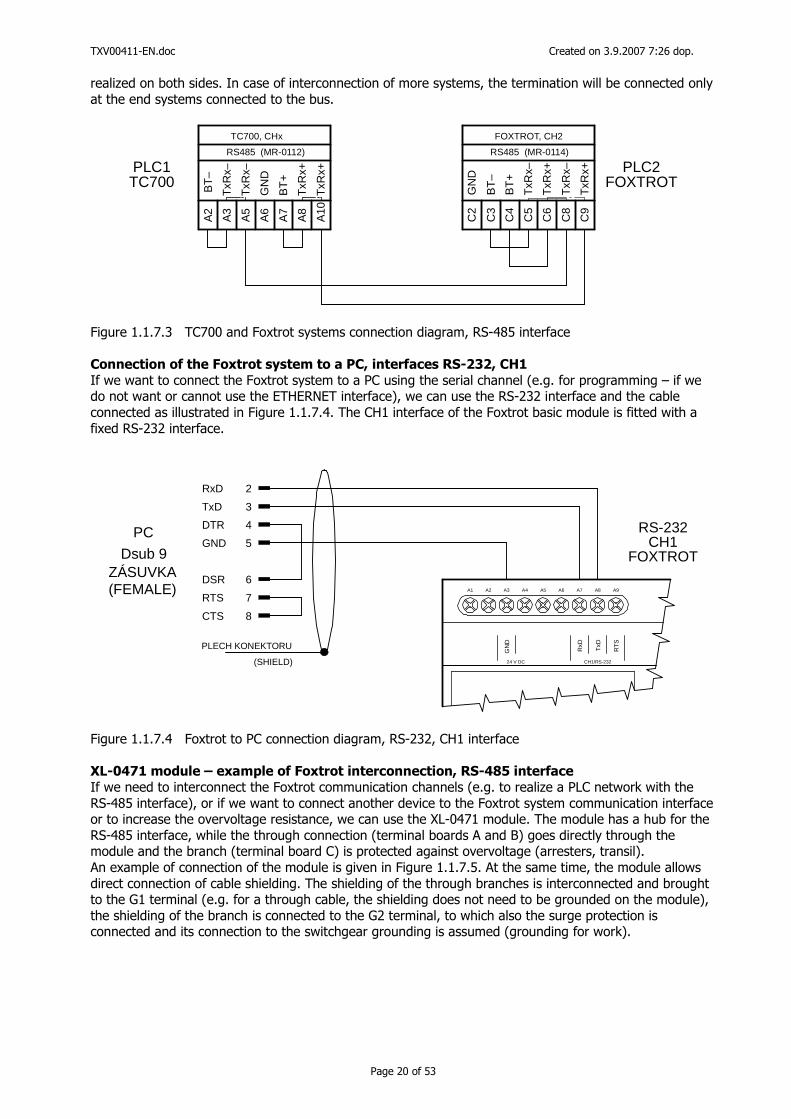
Figure 1.1.7.2 Two Foxtrot systems connection diagram, RS-485 interface (MR-0114 submodule) Interconnection of the TC700 and Foxtrot systems via the RS-485 interface
The interconnection of the TC700 and NS950 systems using a serial channel with the RS-485 interface is illustrated in Figure 1.1.7.3. The interconnection assumes two systems and thus the bus termination is
BT+ Positive terminal of bus termination circuit BT– Negative terminal of bus termination circuit GND Signal ground (common terminal) of the interface TxRx+ Positive signal terminal of the RS-485 interface TxRx– Negative signal terminal of the RS-485 interface Notes 1.Terminals (signals) labelled identically are interconnected inside the submodule. 2.The terminating impedance of the bus is realized using a 150Ω resistor. 3.All terminals are galvanically isolated from the other system circuits.
TXV00411-EN.doc Created on 3.9.2007 7:26 dop.
Page 20 of 53
realized on both sides. In case of interconnection of more systems, the termination will be connected only at the end systems connected to the bus.
PLC1TC700
PLC2FOXTROT
C5
T
xRx–
C8
T
xRx–
C2
G
ND
C4
B
T+
C3
B
T–
C6
T
xRx+
C9
T
xRx+
FOXTROT, CH2
RS485 (MR-0114)
A3
T
xRx–
A5
T
xRx–
A6
G
ND
A7
B
T+
A2
B
T–
A8
T
xRx+
A10
TxR
x+
TC700, CHx
RS485 (MR-0112)
Figure 1.1.7.3 TC700 and Foxtrot systems connection diagram, RS-485 interface Connection of the Foxtrot system to a PC, interfaces RS-232, CH1
If we want to connect the Foxtrot system to a PC using the serial channel (e.g. for programming – if we do not want or cannot use the ETHERNET interface), we can use the RS-232 interface and the cable connected as illustrated in Figure 1.1.7.4. The CH1 interface of the Foxtrot basic module is fitted with a fixed RS-232 interface.
RS-232CH1
FOXTROT
PC
Dsub 9
(FEMALE)ZÁSUVKA
PLECH KONEKTORU
(SHIELD)
RxD 2
CTS 8
RTS 7
DSR 6
DTR 4
GND 5
TxD 3
A1 A2 A3 A4 A5 A6 A7 A8 A9
TxD
RxD
RT
S
CH1/RS-232
GN
D
24 V DC
Figure 1.1.7.4 Foxtrot to PC connection diagram, RS-232, CH1 interface XL-0471 module – example of Foxtrot interconnection, RS-485 interface
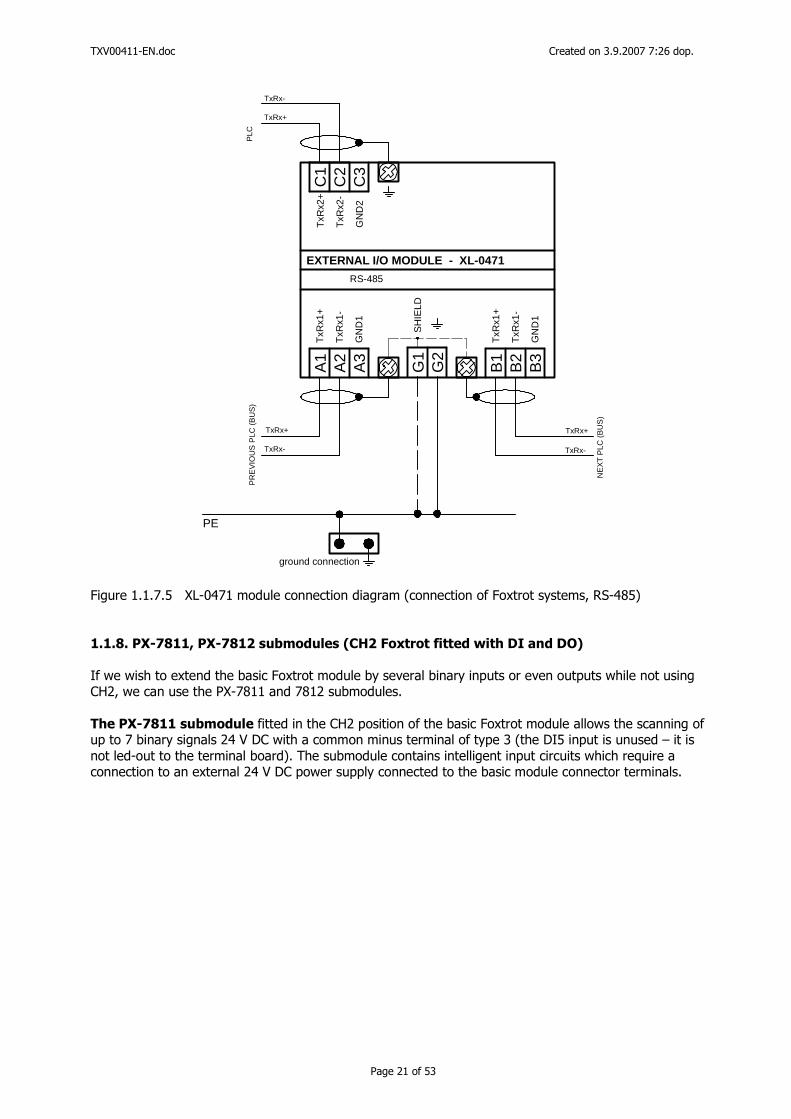
If we need to interconnect the Foxtrot communication channels (e.g. to realize a PLC network with the RS-485 interface), or if we want to connect another device to the Foxtrot system communication interface or to increase the overvoltage resistance, we can use the XL-0471 module. The module has a hub for the RS-485 interface, while the through connection (terminal boards A and B) goes directly through the module and the branch (terminal board C) is protected against overvoltage (arresters, transil). An example of connection of the module is given in Figure 1.1.7.5. At the same time, the module allows direct connection of cable shielding. The shielding of the through branches is interconnected and brought to the G1 terminal (e.g. for a through cable, the shielding does not need to be grounded on the module), the shielding of the branch is connected to the G2 terminal, to which also the surge protection is connected and its connection to the switchgear grounding is assumed (grounding for work).
TXV00411-EN.doc Created on 3.9.2007 7:26 dop.
Page 21 of 53
ground connection
EXTERNAL I/O MODULE - XL-0471
RS-485
PE
TxR
x2+
TxR
x1+
SH
IELD
TxR
x1+
TxR
x2-
TxR
x1-
TxR
x1-
GN
D2
GN
D1
GN
D1
A1
A2
A3
B1
B2
B3
G1
G2
C1
C2
C3
NE
XT
PLC
(B
US
)
PR
EV
IOU
S P
LC (
BU
S)
PLC
TxRx+
TxRx+
TxRx+
TxRx-
TxRx-
TxRx-
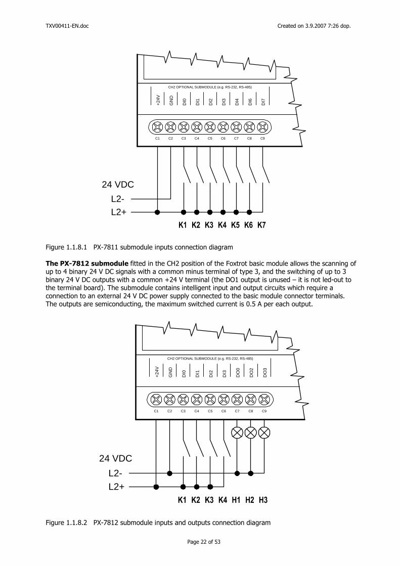
Figure 1.1.7.5 XL-0471 module connection diagram (connection of Foxtrot systems, RS-485) 1.1.8. PX-7811, PX-7812 submodules (CH2 Foxtrot fitted with DI and DO) If we wish to extend the basic Foxtrot module by several binary inputs or even outputs while not using CH2, we can use the PX-7811 and 7812 submodules. The PX-7811 submodule fitted in the CH2 position of the basic Foxtrot module allows the scanning of up to 7 binary signals 24 V DC with a common minus terminal of type 3 (the DI5 input is unused – it is not led-out to the terminal board). The submodule contains intelligent input circuits which require a connection to an external 24 V DC power supply connected to the basic module connector terminals.
TXV00411-EN.doc Created on 3.9.2007 7:26 dop.
Page 22 of 53
C1 C2 C3 C4 C5 C6 C7 C8 C9
CH2 OPTIONAL SUBMODULE (e.g. RS-232, RS-485)
+24
V
DI7
DI6
DI4
DI3
DI2
DI1
DI0
GN
D
L2+L2-
24 VDC
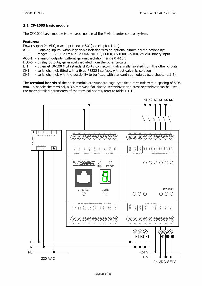
Figure 1.1.8.1 PX-7811 submodule inputs connection diagram The PX-7812 submodule fitted in the CH2 position of the Foxtrot basic module allows the scanning of up to 4 binary 24 V DC signals with a common minus terminal of type 3, and the switching of up to 3 binary 24 V DC outputs with a common +24 V terminal (the DO1 output is unused – it is not led-out to the terminal board). The submodule contains intelligent input and output circuits which require a connection to an external 24 V DC power supply connected to the basic module connector terminals. The outputs are semiconducting, the maximum switched current is 0.5 A per each output.
C1 C2 C3 C4 C5 C6 C7 C8 C9
CH2 OPTIONAL SUBMODULE (e.g. RS-232, RS-485)
+24
V
DO
3
DO
2
DO
0
DI3
DI2
DI1
DI0
GN
D
L2+L2-
24 VDC
Figure 1.1.8.2 PX-7812 submodule inputs and outputs connection diagram
TXV00411-EN.doc Created on 3.9.2007 7:26 dop.
Page 23 of 53
1.2. CP-1005 basic module
The CP-1005 basic module is the basic module of the Foxtrot series control system. Features: Power supply 24 VDC, max. input power 8W (see chapter 1.1.1) AI0-5 - 6 analog inputs, without galvanic isolation with an optional binary input functionality: - ranges: 10 V, 0÷20 mA, 4÷20 mA, Ni1000, Pt100, OV1000, OV100, 24 VDC binary input AO0-1 - 2 analog outputs, without galvanic isolation, range 0 ÷10 V DO0-5 - 6 relay outputs, galvanically isolated from the other circuits ETH - Ethernet 10/100 Mbit (standard RJ-45 connector), galvanically isolated from the other circuits CH1 - serial channel, fitted with a fixed RS232 interface, without galvanic isolation CH2 - serial channel, with the possibility to be fitted with standard submodules (see chapter 1.1.5). The terminal boards of the basic module are standard cage-type fixed terminals with a spacing of 5.08 mm. To handle the terminal, a 3.5 mm wide flat bladed screwdriver or a cross screwdriver can be used. For more detailed parameters of the terminal boards, refer to table 1.1.1.
230 V AC
OUTPUT 24 V DC / 2 A
PS
50
/24
U N
+ ++ – ––
L
0 V+24 V
N
PE
230 VAC24 VDC SELV
A1 A2 A3 A4 A5 A6 A7 A8 A9
C1 C2 C3 C4 C5 C6 C7 C8 C9
B1 B2 B3 B4 B5 B6 B7 B8 B9
D1 D2 D3 D4 D5 D6 D7 D8 D9
CP-1005
RUN ERROR
ETHERNET MODE
TC
L2+
TC
L2-
GN
D
+24
V
CIB
1+
CIB
1-
TxD
RxD
RT
S
TC LINE 24 V DC CIB LINE CH1/RS-232
CO
M1
DO
0
DO
1
DO
2
CO
M2
DO
3
DO
4
DO
5
DIGITAL OUTPUTS
GN
D
AO
1
AO
0
DI4
DI3
DI2
DI1
DI0
AN. OUTPUTS DIGITAL/ANALOG INPUTS
AI4
AI3
AI2
AI1
AI0
DI5
AI5
+5V
CH2 OPTIONAL SUBMODULE (e.g. RS-232, RS-485)
+5V GN
DG
ND
RT
SB
T- - BT
+
CT
ST
xRx-
- TxR
x+
RxD
- TxD
TxR
x-
- TxR
x+
TXV00411-EN.doc Created on 3.9.2007 7:26 dop.
Page 24 of 53
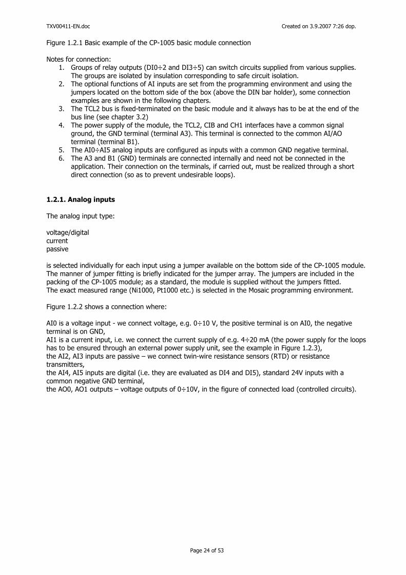
Figure 1.2.1 Basic example of the CP-1005 basic module connection Notes for connection:
1. Groups of relay outputs (DI0÷2 and DI3÷5) can switch circuits supplied from various supplies. The groups are isolated by insulation corresponding to safe circuit isolation.
2. The optional functions of AI inputs are set from the programming environment and using the jumpers located on the bottom side of the box (above the DIN bar holder), some connection examples are shown in the following chapters.
3. The TCL2 bus is fixed-terminated on the basic module and it always has to be at the end of the bus line (see chapter 3.2)
4. The power supply of the module, the TCL2, CIB and CH1 interfaces have a common signal ground, the GND terminal (terminal A3). This terminal is connected to the common AI/AO terminal (terminal B1).
5. The AI0÷AI5 analog inputs are configured as inputs with a common GND negative terminal. 6. The A3 and B1 (GND) terminals are connected internally and need not be connected in the
application. Their connection on the terminals, if carried out, must be realized through a short direct connection (so as to prevent undesirable loops).
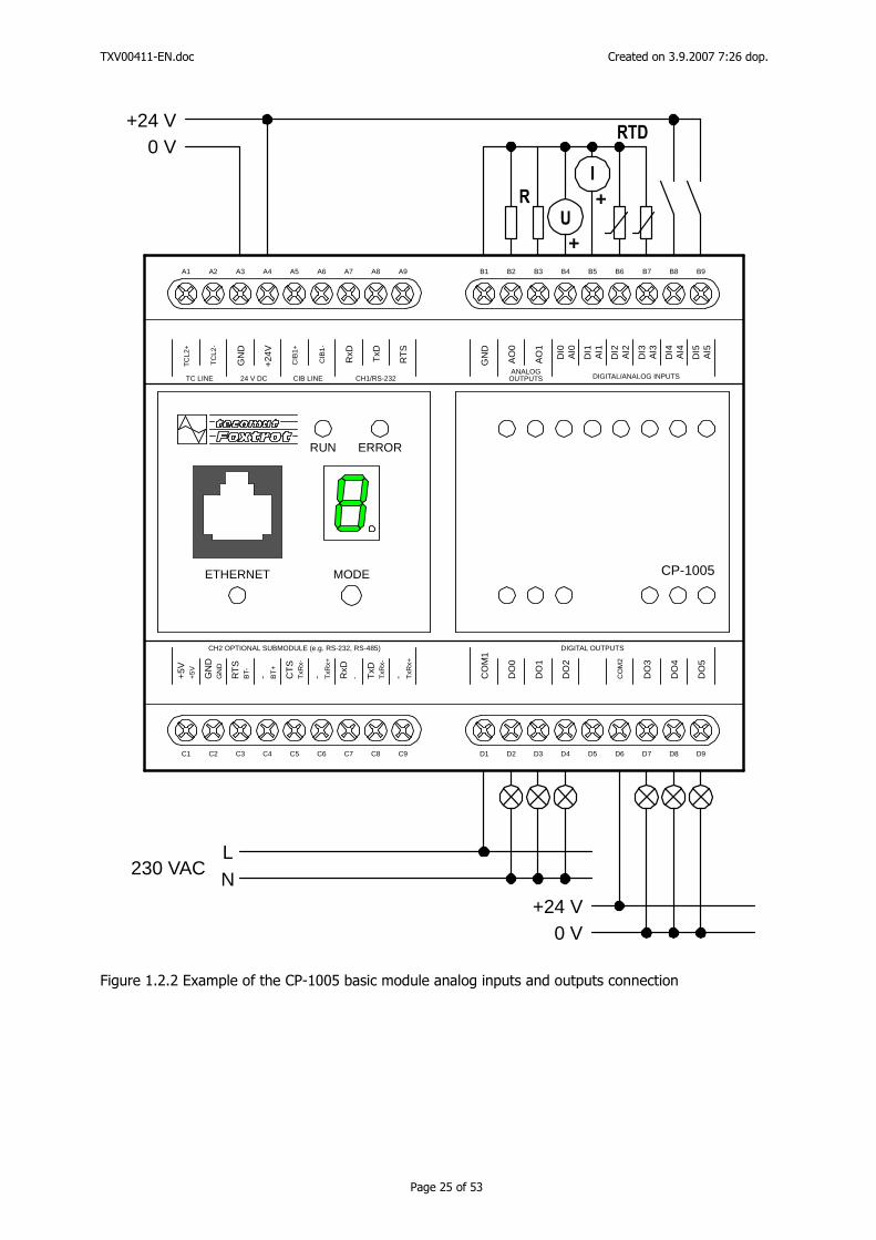
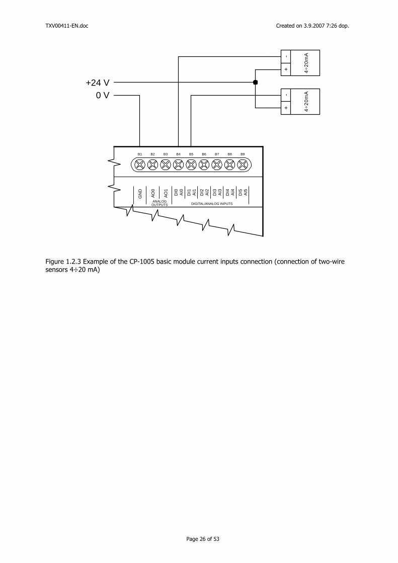
1.2.1. Analog inputs The analog input type: voltage/digital current passive is selected individually for each input using a jumper available on the bottom side of the CP-1005 module. The manner of jumper fitting is briefly indicated for the jumper array. The jumpers are included in the packing of the CP-1005 module; as a standard, the module is supplied without the jumpers fitted. The exact measured range (Ni1000, Pt1000 etc.) is selected in the Mosaic programming environment. Figure 1.2.2 shows a connection where: AI0 is a voltage input - we connect voltage, e.g. 0÷10 V, the positive terminal is on AI0, the negative terminal is on GND, AI1 is a current input, i.e. we connect the current supply of e.g. 4÷20 mA (the power supply for the loops has to be ensured through an external power supply unit, see the example in Figure 1.2.3), the AI2, AI3 inputs are passive – we connect twin-wire resistance sensors (RTD) or resistance transmitters, the AI4, AI5 inputs are digital (i.e. they are evaluated as DI4 and DI5), standard 24V inputs with a common negative GND terminal, the AO0, AO1 outputs – voltage outputs of 0÷10V, in the figure of connected load (controlled circuits).
TXV00411-EN.doc Created on 3.9.2007 7:26 dop.
Page 25 of 53
L
0 V
0 V
+24 V
+24 V
N230 VAC
A1 A2 A3 A4 A5 A6 A7 A8 A9
C1 C2 C3 C4 C5 C6 C7 C8 C9
B1 B2 B3 B4 B5 B6 B7 B8 B9
D1 D2 D3 D4 D5 D6 D7 D8 D9
CP-1005
RUN ERROR
ETHERNET MODE
TC
L2+
TC
L2-
GN
D
+24
V
CIB
1+
CIB
1-
TxD
RxD
RT
S
TC LINE 24 V DC CIB LINE CH1/RS-232
CO
M1
DO
0
DO
1
DO
2
CO
M2
DO
3
DO
4
DO
5
DIGITAL OUTPUTS
GN
D
AO
1
AO
0
DI4
DI3
DI2
DI1
DI0
ANALOGOUTPUTS DIGITAL/ANALOG INPUTS
AI4
AI3
AI2
AI1
AI0
DI5
AI5
+5V
CH2 OPTIONAL SUBMODULE (e.g. RS-232, RS-485)
+5V
GN
DG
ND
RT
SB
T- - BT
+
CT
ST
xRx-
- TxR
x+
RxD
- TxD
TxR
x-
- TxR
x+
+
+
Figure 1.2.2 Example of the CP-1005 basic module analog inputs and outputs connection
TXV00411-EN.doc Created on 3.9.2007 7:26 dop.
Page 26 of 53
0 V+24 V
B1 B2 B3 B4 B5 B6 B7 B8 B9
GN
D
AO
1
AO
0
DI4
DI3
DI2
DI1
DI0
ANALOGOUTPUTS DIGITAL/ANALOG INPUTS
AI4
AI3
AI2
AI1
AI0
DI5
AI5
4÷2
0m
A
+-
4÷2
0m
A
+-
Figure 1.2.3 Example of the CP-1005 basic module current inputs connection (connection of two-wire sensors 4÷20 mA)
TXV00411-EN.doc Created on 3.9.2007 7:26 dop.
Page 27 of 53
1.3. CP-1014 basic module
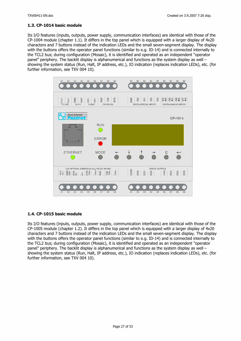
Its I/O features (inputs, outputs, power supply, communication interfaces) are identical with those of the CP-1004 module (chapter 1.1). It differs in the top panel which is equipped with a larger display of 4x20 characters and 7 buttons instead of the indication LEDs and the small seven-segment display. The display with the buttons offers the operator panel functions (similar to e.g. ID-14) and is connected internally to the TCL2 bus; during configuration (Mosaic), it is identified and operated as an independent “operator panel” periphery. The backlit display is alphanumerical and functions as the system display as well – showing the system status (Run, Halt, IP address, etc.), IO indication (replaces indication LEDs), etc. (for further information, see TXV 004 10).
1.4. CP-1015 basic module Its I/O features (inputs, outputs, power supply, communication interfaces) are identical with those of the CP-1005 module (chapter 1.2). It differs in the top panel which is equipped with a larger display of 4x20 characters and 7 buttons instead of the indication LEDs and the small seven-segment display. The display with the buttons offers the operator panel functions (similar to e.g. ID-14) and is connected internally to the TCL2 bus; during configuration (Mosaic), it is identified and operated as an independent “operator panel” periphery. The backlit display is alphanumerical and functions as the system display as well – showing the system status (Run, Halt, IP address, etc.), IO indication (replaces indication LEDs), etc. (for further information, see TXV 004 10).
TXV00411-EN.doc Created on 3.9.2007 7:26 dop.
Page 28 of 53
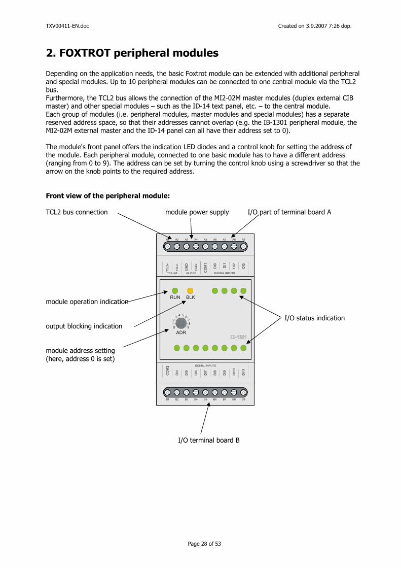
2. FOXTROT peripheral modules Depending on the application needs, the basic Foxtrot module can be extended with additional peripheral and special modules. Up to 10 peripheral modules can be connected to one central module via the TCL2 bus. Furthermore, the TCL2 bus allows the connection of the MI2-02M master modules (duplex external CIB master) and other special modules – such as the ID-14 text panel, etc. – to the central module. Each group of modules (i.e. peripheral modules, master modules and special modules) has a separate reserved address space, so that their addresses cannot overlap (e.g. the IB-1301 peripheral module, the MI2-02M external master and the ID-14 panel can all have their address set to 0). The module's front panel offers the indication LED diodes and a control knob for setting the address of the module. Each peripheral module, connected to one basic module has to have a different address (ranging from 0 to 9). The address can be set by turning the control knob using a screwdriver so that the arrow on the knob points to the required address. Front view of the peripheral module: TCL2 bus connection module power supply I/O part of terminal board A module operation indication I/O status indication output blocking indication module address setting (here, address 0 is set) I/O terminal board B
TXV00411-EN.doc Created on 3.9.2007 7:26 dop.
Page 29 of 53
2.1. IB-1301 expansion module
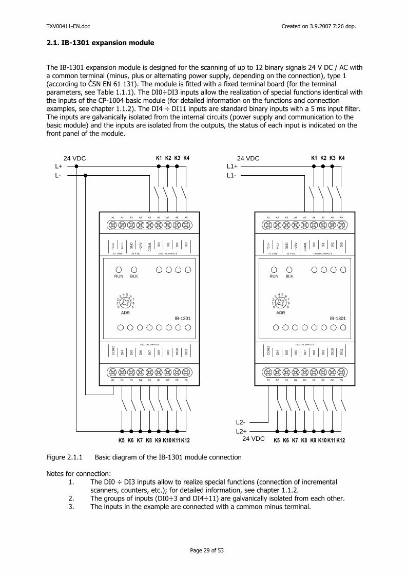
The IB-1301 expansion module is designed for the scanning of up to 12 binary signals 24 V DC / AC with a common terminal (minus, plus or alternating power supply, depending on the connection), type 1 (according to ČSN EN 61 131). The module is fitted with a fixed terminal board (for the terminal parameters, see Table 1.1.1). The DI0÷DI3 inputs allow the realization of special functions identical with the inputs of the CP-1004 basic module (for detailed information on the functions and connection examples, see chapter 1.1.2). The DI4 ÷ DI11 inputs are standard binary inputs with a 5 ms input filter. The inputs are galvanically isolated from the internal circuits (power supply and communication to the basic module) and the inputs are isolated from the outputs, the status of each input is indicated on the front panel of the module.
A1 A2 A3 A4 A5 A6 A7 A8 A9
B1 B2 B3 B4 B5 B6 B7 B8 B9
CO
M2
DI4
DI5
DI6
DI7
DI8
DI9
DI1
0
DI1
1
TC
L2+
TC
L2-
GN
D
+24V
CO
M1
DI0
DI1
DI2
DI3
TC LINE 24 V DC DIGITAL INPUTS
DIGITAL INPUTS
IB-1301ADR
012
3 4 5 678
9
RUN BLK
A1 A2 A3 A4 A5 A6 A7 A8 A9
B1 B2 B3 B4 B5 B6 B7 B8 B9
CO
M2
DI4
DI5
DI6
DI7
DI8
DI9
DI1
0
DI1
1
TC
L2+
TC
L2-
GN
D
+24V
CO
M1
DI0
DI1
DI2
DI3
TC LINE 24 V DC DIGITAL INPUTS
DIGITAL INPUTS
IB-1301ADR
012
3 4 5 678
9
RUN BLK
L+ L1+
L2+
L- L1-
L2-
24 VDC 24 VDC
24 VDC
Figure 2.1.1 Basic diagram of the IB-1301 module connection Notes for connection:
1. The DI0 ÷ DI3 inputs allow to realize special functions (connection of incremental scanners, counters, etc.); for detailed information, see chapter 1.1.2.
2. The groups of inputs (DI0÷3 and DI4÷11) are galvanically isolated from each other. 3. The inputs in the example are connected with a common minus terminal.
TXV00411-EN.doc Created on 3.9.2007 7:26 dop.
Page 30 of 53
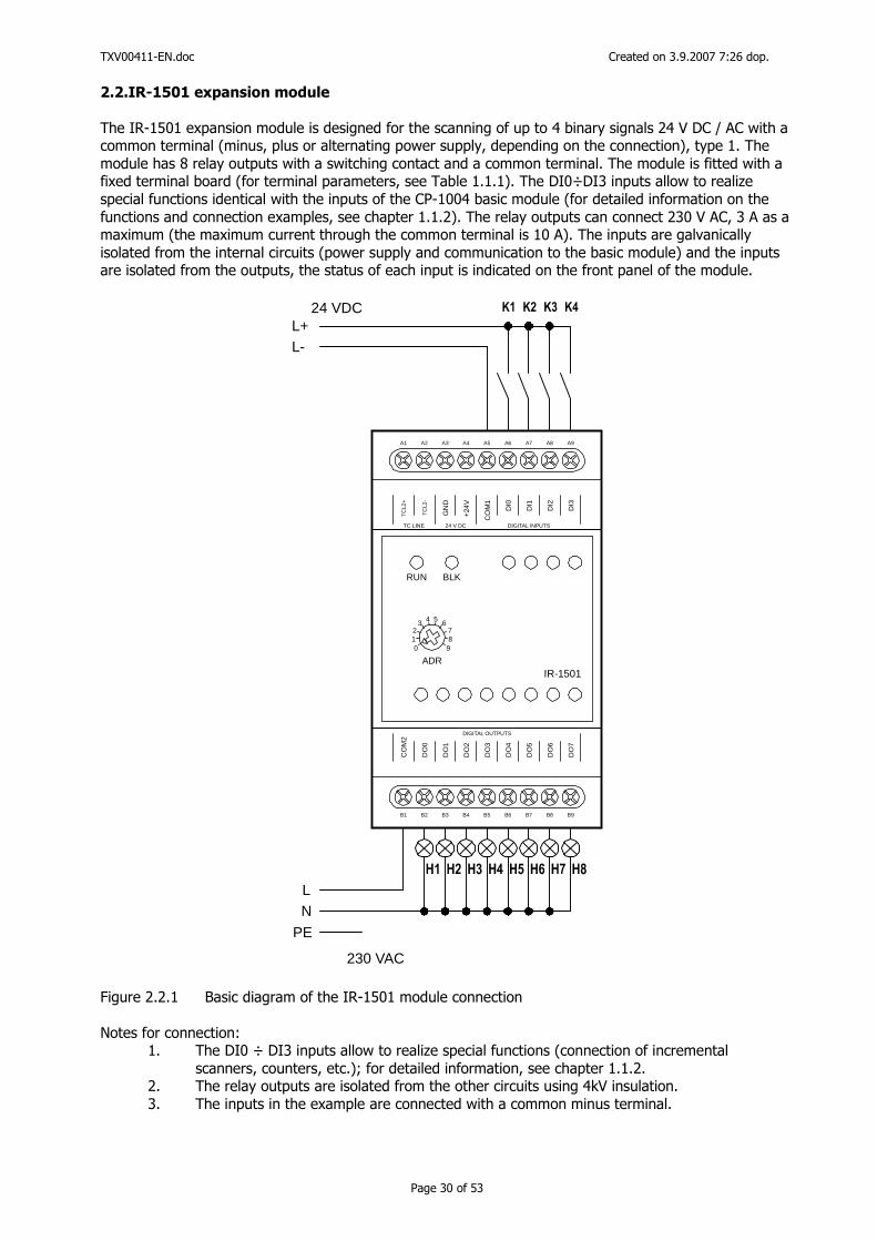
2.2.IR-1501 expansion module
The IR-1501 expansion module is designed for the scanning of up to 4 binary signals 24 V DC / AC with a common terminal (minus, plus or alternating power supply, depending on the connection), type 1. The module has 8 relay outputs with a switching contact and a common terminal. The module is fitted with a fixed terminal board (for terminal parameters, see Table 1.1.1). The DI0÷DI3 inputs allow to realize special functions identical with the inputs of the CP-1004 basic module (for detailed information on the functions and connection examples, see chapter 1.1.2). The relay outputs can connect 230 V AC, 3 A as a maximum (the maximum current through the common terminal is 10 A). The inputs are galvanically isolated from the internal circuits (power supply and communication to the basic module) and the inputs are isolated from the outputs, the status of each input is indicated on the front panel of the module.
L+L-
24 VDC
A1 A2 A3 A4 A5 A6 A7 A8 A9
B1 B2 B3 B4 B5 B6 B7 B8 B9
CO
M2
DO
0
DO
1
DO
2
DO
3
DO
4
DO
5
DO
6
DO
7
TC
L2+
TC
L2-
GN
D
+24
V
CO
M1
DI0
DI1
DI2
DI3
TC LINE 24 V DC DIGITAL INPUTS
DIGITAL OUTPUTS
IR-1501ADR
012
3 4 5 678
9
RUN BLK
LN
PE
230 VAC
Figure 2.2.1 Basic diagram of the IR-1501 module connection Notes for connection:
1. The DI0 ÷ DI3 inputs allow to realize special functions (connection of incremental scanners, counters, etc.); for detailed information, see chapter 1.1.2.
2. The relay outputs are isolated from the other circuits using 4kV insulation. 3. The inputs in the example are connected with a common minus terminal.
TXV00411-EN.doc Created on 3.9.2007 7:26 dop.
Page 31 of 53
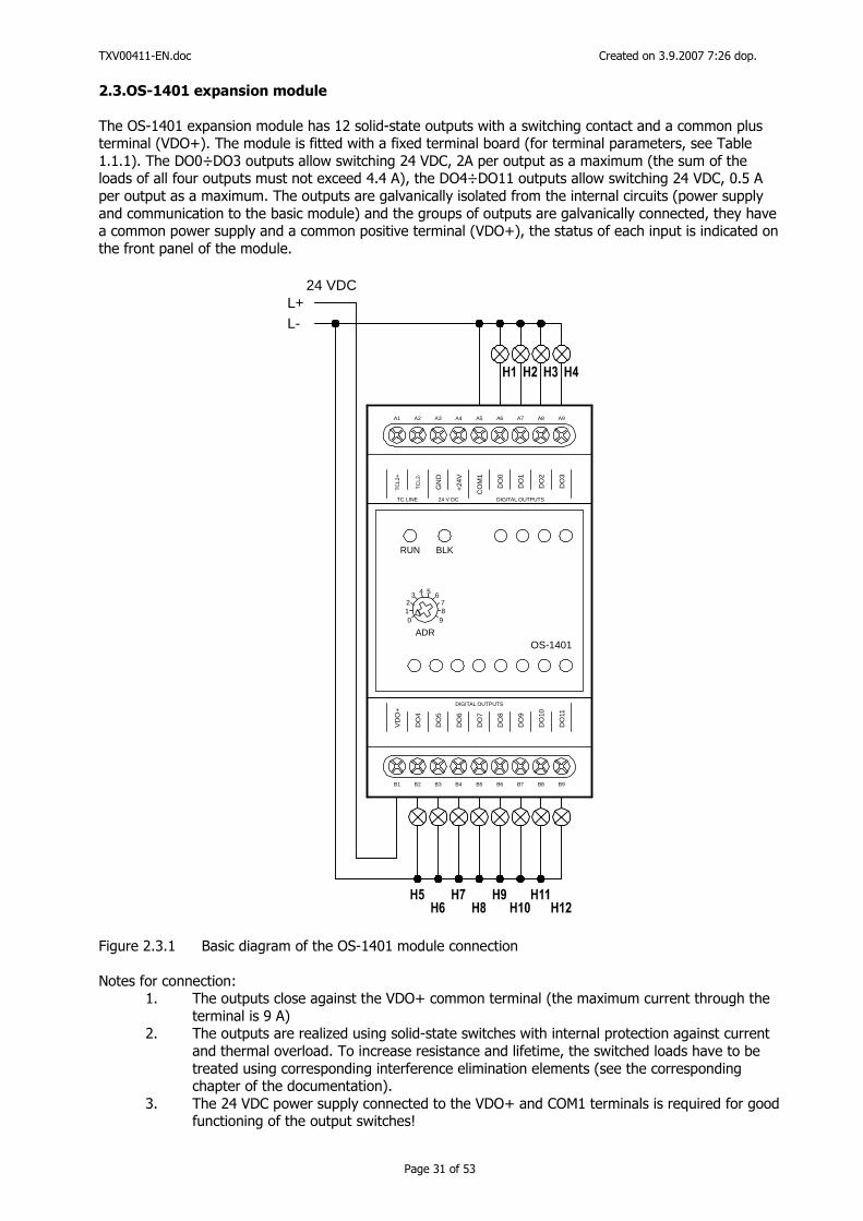
2.3.OS-1401 expansion module
The OS-1401 expansion module has 12 solid-state outputs with a switching contact and a common plus terminal (VDO+). The module is fitted with a fixed terminal board (for terminal parameters, see Table 1.1.1). The DO0÷DO3 outputs allow switching 24 VDC, 2A per output as a maximum (the sum of the loads of all four outputs must not exceed 4.4 A), the DO4÷DO11 outputs allow switching 24 VDC, 0.5 A per output as a maximum. The outputs are galvanically isolated from the internal circuits (power supply and communication to the basic module) and the groups of outputs are galvanically connected, they have a common power supply and a common positive terminal (VDO+), the status of each input is indicated on the front panel of the module.
L+L-
24 VDC
A1 A2 A3 A4 A5 A6 A7 A8 A9
B1 B2 B3 B4 B5 B6 B7 B8 B9
VD
O+
DO
4
DO
5
DO
6
DO
7
DO
8
DO
9
DO
10
DO
11
TC
L2+
TC
L2-
GN
D
+24
V
CO
M1
DO
0
DO
1
DO
2
DO
3
TC LINE 24 V DC DIGITAL OUTPUTS
DIGITAL OUTPUTS
OS-1401ADR
012
3 4 5 678
9
RUN BLK
Figure 2.3.1 Basic diagram of the OS-1401 module connection Notes for connection:
1. The outputs close against the VDO+ common terminal (the maximum current through the terminal is 9 A)
2. The outputs are realized using solid-state switches with internal protection against current and thermal overload. To increase resistance and lifetime, the switched loads have to be treated using corresponding interference elimination elements (see the corresponding chapter of the documentation).
3. The 24 VDC power supply connected to the VDO+ and COM1 terminals is required for good functioning of the output switches!
TXV00411-EN.doc Created on 3.9.2007 7:26 dop.
Page 32 of 53
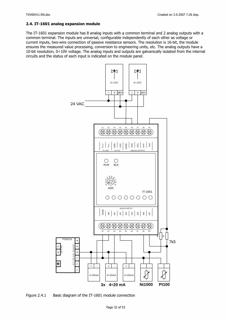
2.4. IT-1601 analog expansion module
The IT-1601 expansion module has 8 analog inputs with a common terminal and 2 analog outputs with a common terminal. The inputs are universal, configurable independently of each other as voltage or current inputs, two-wire connection of passive resistance sensors. The resolution is 16-bit, the module ensures the measured value processing, conversion to engineering units, etc. The analog outputs have a 10-bit resolution, 0÷10V voltage. The analog inputs and outputs are galvanically isolated from the internal circuits and the status of each input is indicated on the module panel.
24 VAC
A1 A2 A3 A4 A5 A6 A7 A8 A9
B1 B2 B3 B4 B5 B6 B7 B8 B9
AG
ND
AI0
AI1
AI2
AI3
AI4
AI5
AI6
AI7
TC
L2+
TC
L2-
GN
D
+24V
AG
ND
AO
0
AO
1
AG
ND
Vre
fTC LINE 24 V DC ANALOG OUTPUTS
ANALOG INPUTS
IT-1601ADR
012
3 4 5 6789
RUN BLK
YY
0÷10V0÷10V
⊥⊥
RR
Ni1000 Pt100
7k5
4÷20mA
+ -
4÷20mA
+ -
4÷20mA
+ -
23
0 V
AC
OU
TP
UT
24
V D
C / 2
A
PS50/24
UN
++
+–
––
3x 4÷20 mA
Figure 2.4.1 Basic diagram of the IT-1601 module connection
TXV00411-EN.doc Created on 3.9.2007 7:26 dop.
Page 33 of 53
Notes for connection: 1. The analog inputs and outputs have a common AGND terminal. 2. To increase the measurement accuracy, it is recommended to connect the input signals
(sensors) as shown in the example, i.e. to use the A8 terminal as the common AGND terminal for measurement of passive resistance sensors
3. Exact voltage of +10.0 V is available on the Vref terminal for supplying the passive resistance sensors (using an external serial resistor).
4. Passive resistance sensors connected using a two-wire connection are supplied via a 7k5 resistor from the Vref terminal. The resistor has to be fitted outside the module in the distributor. The other end of the sensor has to be connected to the AGND terminal no. A8 ! (we recommend to use the MT-1691 module).
5. The accuracy of the 7k5 resistor has a key influence on the accuracy of passive sensors measurement. The basic accuracy of the resistors used in the MT-1691 module is 0.1% with a temperature coefficient of no more than 25 ppm.
6. The current ranges (20 mA, etc.) can be switched-over from the Mosaic programming environment (the module is not fitted with internal jumpers).
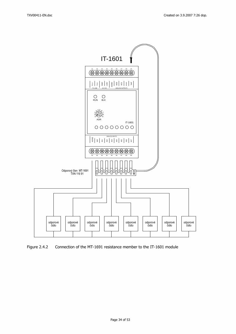
MT-1691 module with resistors.
The R resistors for supplying the passive sensors need not be purchased and fitted manually in the application, since it is possible to use the ready-made MT-1691 module, which can be slid in the bottom terminal board as shown in Figure 2.4.2 while fixing the free end of the cable in the A9 terminal. The outlets of the MT-1691 resistance member should be slid directly in the terminals along with the connecting cables (we recommend to slide the connecting cables in under the outlets of the resistance member). The unused outlets of the resistance member can be broken off and these inputs can then be used as analog inputs with a different range. The outlets can only be broken off from the end to which no cable with reference voltage is connected. The SW configuration is carried out in the Mosaic programming environment.
TXV00411-EN.doc Created on 3.9.2007 7:26 dop.
Page 34 of 53
A1 A2 A3 A4 A5 A6 A7 A8 A9
B1 B2 B3 B4 B5 B6 B7 B8 B9
AG
ND
AI0
AI1
AI2
AI3
AI4
AI5
AI6
AI7
TC
L2+
TC
L2-
GN
D
+24V
AG
ND
AO
0
AO
1
AG
ND
Vre
f
TC LINE 24 V DC ANALOG OUTPUTS
ANALOG INPUTS
IT-1601ADR
012
3 4 5 678
9
RUN BLK
IT-1601
Figure 2.4.2 Connection of the MT-1691 resistance member to the IT-1601 module
TXV00411-EN.doc Created on 3.9.2007 7:26 dop.
Page 35 of 53
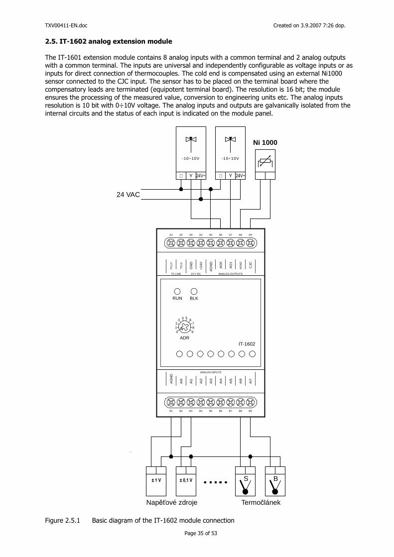
2.5. IT-1602 analog extension module
The IT-1601 extension module contains 8 analog inputs with a common terminal and 2 analog outputs with a common terminal. The inputs are universal and independently configurable as voltage inputs or as inputs for direct connection of thermocouples. The cold end is compensated using an external Ni1000 sensor connected to the CJC input. The sensor has to be placed on the terminal board where the compensatory leads are terminated (equipotent terminal board). The resolution is 16 bit; the module ensures the processing of the measured value, conversion to engineering units etc. The analog inputs resolution is 10 bit with 0÷10V voltage. The analog inputs and outputs are galvanically isolated from the internal circuits and the status of each input is indicated on the module panel.
24 VAC
A1 A2 A3 A4 A5 A6 A7 A8 A9
B1 B2 B3 B4 B5 B6 B7 B8 B9
AG
ND
AI0
AI1
AI2
AI3
AI4
AI5
AI6
AI7
TC
L2+
TC
L2-
GN
D
+24
V
AG
ND
AO
0
AO
1
AG
ND
CJC
TC LINE 24 V DC ANALOG OUTPUTS
ANALOG INPUTS
IT-1602ADR
012
3 4 5 678
9
RUN BLK
YY
-10÷10V-10÷10V
⊥⊥
Ni 1000
TermočlánekNapěťové zdroje
BS
Figure 2.5.1 Basic diagram of the IT-1602 module connection

TXV00411-EN.doc Created on 3.9.2007 7:26 dop.
Page 36 of 53
Notes for connection: 1. The analog inputs and outputs have a common AGND terminal. 2. To increase the measurement accuracy, it is recommended to connect the input signals
(sensors) according to the example, i.e. to use the B1 terminal as the common AGND terminal for the analog inputs (A5 for analog outputs and A8 for cold end compensation)
3. The CJC input is only designed for cold end measurement in the case of direct thermocouple measurement. The connected sensor has to be of the Ni1000 type.
TXV00411-EN.doc Created on 3.9.2007 7:26 dop.
Page 37 of 53
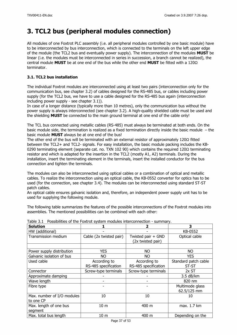
3. TCL2 bus (peripheral modules connection) All modules of one Foxtrot PLC assembly (i.e. all peripheral modules controlled by one basic module) have to be interconnected by bus interconnection, which is connected to the terminals on the left upper edge of the module (the TCL2 bus and eventually power supply). The interconnection of the modules MUST be linear (i.e. the modules must be interconnected in series in succession, a branch cannot be realized), the central module MUST be at one end of the bus while the other end MUST be fitted with a 120Ω terminator. 3.1. TCL2 bus installation The individual Foxtrot modules are interconnected using at least two pairs (interconnection only for the communication bus, see chapter 3.2) of cables designed for the RS-485 bus, or cables including power supply (for the TCL2 bus, we have to use a cable designed for the RS-485 bus again (interconnection including power supply - see chapter 3.1)). In case of a longer distance (typically more than 10 metres), only the communication bus without the power supply is always interconnected (see chapter 3.2). A high-quality shielded cable must be used and the shielding MUST be connected to the main ground terminal at one end of the cable only! The TCL bus connected using metallic cables (RS-485) must always be terminated at both ends. On the basic module side, the termination is realized as a fixed termination directly inside the basic module – the basic module MUST always be at one end of the bus! The other end of the bus will be terminated with an external resistor of approximately 120Ω fitted between the TCL2+ and TCL2- signals. For easy installation, the basic module packing includes the KB-0290 terminating element (separate cat. no. TXN 102 90) which contains the required 120Ω terminating resistor and which is adapted for the insertion in the TCL2 (mostly A1, A2) terminals. During the installation, insert the terminating element in the terminals, insert the installed conductor for the bus connection and tighten the terminals. The modules can also be interconnected using optical cables or a combination of optical and metallic cables. To realize the interconnection using an optical cable, the KB-0552 converter for optics has to be used (for the connection, see chapter 3.4). The modules can be interconnected using standard ST-ST patch cables. An optical cable ensures galvanic isolation and, therefore, an independent power supply unit has to be used for supplying the following module. The following table summarizes the features of the possible interconnections of the Foxtrot modules into assemblies. The mentioned possibilities can be combined with each other: Table 3.1 Possibilities of the Foxtrot system modules interconnection - summary. Solution 1 2 3
HW (additional) - - KB-0552 Transmission medium Cable (2x twisted pair) Twisted pair + GND
(2x twisted pair) Optical cable
Power supply distribution YES NO NO Galvanic isolation of bus NO NO YES Used cable According to
RS-485 specification According to
RS-485 specification Standard patch cable
ST-ST Connector Screw-type terminals Screw-type terminals 2x ST Approximate damping - - 3.5 dB/km Wave length - - 820 nm Fibre type - - Multimode glass
62.5/125 mm Max. number of I/O modules to one CP
10 10 10
Max. length of one bus segment
10 m 400 m max. 1.7 km
Max. total bus length 10 m 400 m Depending on the
TXV00411-EN.doc Created on 3.9.2007 7:26 dop.
Page 38 of 53
number of segments For detailed information see chapter 3.1 chapter 3.2 [2]
Notes on the individual solutions:
1. The basic method of interconnection including power supply. Suitable for assemblies with several modules in one switchgear. This solution is limited by the maximum bus length (power supply line).
2. The connection in case of longer distances between modules – the control system is distributed in several boxes in the technology, etc. Each module (or a group of modules) has to have its own power supply unit. The interconnection of the TCL2 bus allows the use of any cable fulfilling the requirements for the RS-485 bus, drawn through the channels, the switchgear bushings.
3. The connection for longer distances (the best solution). Since the lengths of the individual segments add up, even kilometre distances of the bus of the entire system can be achieved. The optical cable ensures galvanic isolation and therefore a power supply unit has to be installed in each module (a group of modules) connected by the optical cable.
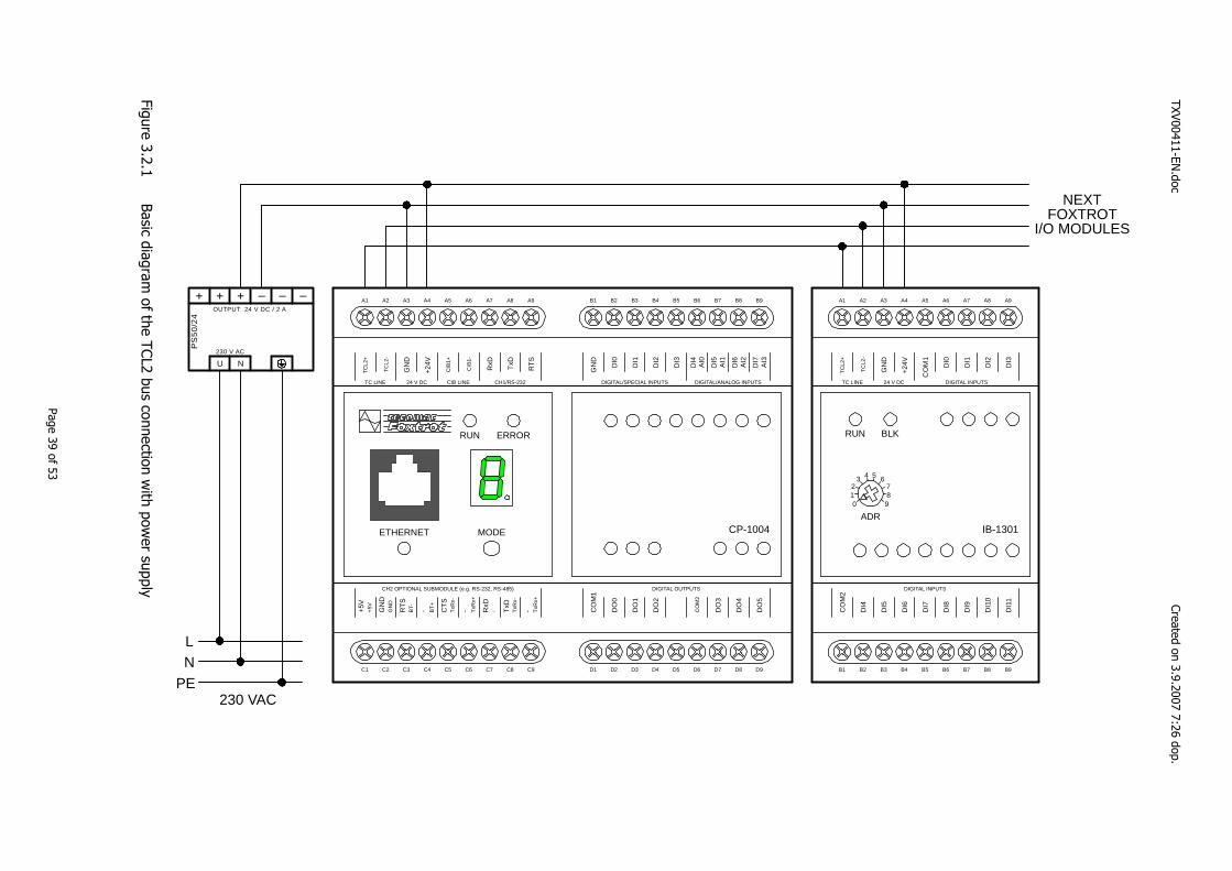
3.2. Connection of expansion modules to the FOXTROT system (TCL2 bus with power supply)
Figure 3.2.1 below shows the basic connection of the expansion modules to the basic module. Peripheral modules are connected including the power supply. The last module on the bus (the most distant one from the basic module) must always be fitted with a terminating resistor of the TCL2 bus (see the resistor in Figure 3.3.1).
TXV00411-EN.doc
Created on 3.9.2007 7:26 dop.
Page 39 of 53
230 V AC
OUTPUT 24 V DC / 2 A
PS
50
/24
U N
+ ++ – ––
LN
PE230 VAC
A1 A2 A3 A4 A5 A6 A7 A8 A9
C1 C2 C3 C4 C5 C6 C7 C8 C9
B1 B2 B3 B4 B5 B6 B7 B8 B9
D1 D2 D3 D4 D5 D6 D7 D8 D9
CP-1004
RUN ERROR
ETHERNET MODE
TC
L2+
TC
L2-
GN
D
+24V
CIB
1+
CIB
1-
TxD
RxD
RT
S
TC LINE 24 V DC CIB LINE CH1/RS-232
CO
M1
DO
0
DO
1
DO
2
CO
M2
DO
3
DO
4
DO
5
DIGITAL OUTPUTSG
ND
DI0
DI1
DI2
DI3
DI4
DIGITAL/SPECIAL INPUTS DIGITAL/ANALOG INPUTS
AI0
DI5
AI1
DI6
AI2
DI7
AI3
+5V
CH2 OPTIONAL SUBMODULE (e.g. RS-232, RS-485)
+5V GN
DG
ND
RT
SB
T- - BT
+
CT
ST
xRx-
- TxR
x+
RxD
- TxD
TxR
x-
- TxR
x+
A1 A2 A3 A4 A5 A6 A7 A8 A9
B1 B2 B3 B4 B5 B6 B7 B8 B9
CO
M2
DI4
DI5
DI6
DI7
DI8
DI9
DI1
0
DI1
1
TC
L2+
TC
L2-
GN
D
+24V
CO
M1
DI0
DI1
DI2
DI3
TC LINE 24 V DC DIGITAL INPUTS
DIGITAL INPUTS
IB-1301ADR
012
3 4 5 6789
RUN BLK
NEXTFOXTROT
I/O MODULES
Figure 3.2.1
Basic diagram of the TC
L2 bus connection with pow
er supply
TXV00411-EN.doc
Created on 3.9.2007 7:26 dop.
Page 40 of 53
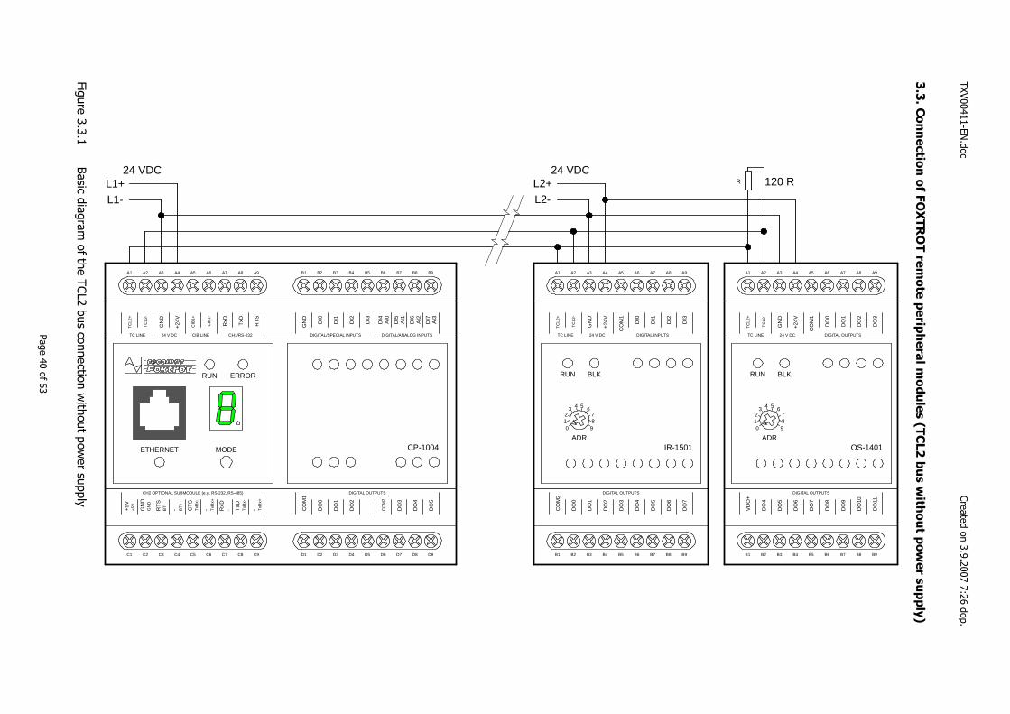
3.3
. Connectio
n o
f FO
XTR
OT re
mote
perip
hera
l module
s (T
CL2 b
us w
ithout p
ow
er s
upply
)
A1 A2 A3 A4 A5 A6 A7 A8 A9
C1 C2 C3 C4 C5 C6 C7 C8 C9
B1 B2 B3 B4 B5 B6 B7 B8 B9
D1 D2 D3 D4 D5 D6 D7 D8 D9
CP-1004
RUN ERROR
ETHERNET MODE
TC
L2+
TC
L2-
GN
D
+24
V
CIB
1+
CIB
1-
TxD
RxD
RT
S
TC LINE 24 V DC CIB LINE CH1/RS-232
CO
M1
DO
0
DO
1
DO
2
CO
M2
DO
3
DO
4
DO
5
DIGITAL OUTPUTS
GN
D
DI0
DI1
DI2
DI3
DI4
DIGITAL/SPECIAL INPUTS DIGITAL/ANALOG INPUTS
AI0
DI5
AI1
DI6
AI2
DI7
AI3
+5V
CH2 OPTIONAL SUBMODULE (e.g. RS-232, RS-485)
+5V GN
DG
ND
RT
SB
T- - BT
+
CT
ST
xRx-
- TxR
x+
RxD
- TxD
TxR
x-
- TxR
x+
A1 A2 A3 A4 A5 A6 A7 A8 A9
B1 B2 B3 B4 B5 B6 B7 B8 B9C
OM
2
DO
0
DO
1
DO
2
DO
3
DO
4
DO
5
DO
6
DO
7
TC
L2+
TC
L2-
GN
D
+24
V
CO
M1
DI0
DI1
DI2
DI3
TC LINE 24 V DC DIGITAL INPUTS
DIGITAL OUTPUTS
IR-1501ADR
012
3 4 5 678
9
RUN BLK
L1+ L2+
L1- L2-
24 VDC 24 VDC
A1 A2 A3 A4 A5 A6 A7 A8 A9
B1 B2 B3 B4 B5 B6 B7 B8 B9
VD
O+
DO
4
DO
5
DO
6
DO
7
DO
8
DO
9
DO
10
DO
11
TC
L2+
TC
L2-
GN
D
+24
V
CO
M1
DO
0
DO
1
DO
2
DO
3
TC LINE 24 V DC DIGITAL OUTPUTS
DIGITAL OUTPUTS
OS-1401ADR
012
3 4 5 6789
RUN BLK
R 120 R
Figure 3.3.1
Basic diagram of the TC
L2 bus connection without pow
er supply
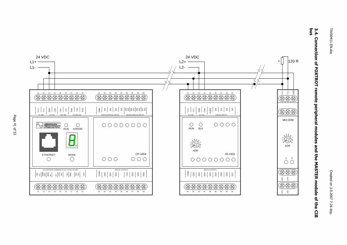
TXV00411-EN.doc
Created on 3.9.2007 7:26 dop.
Page 41 of 53
3.4
. Connectio
n o
f FO
XTR
OT re
mote
perip
hera
l module
s a
nd th
e M
ASTER m
odule
of th
e C
IB
bus
A1 A2 A3 A4 A5 A6 A7 A8 A9
C1 C2 C3 C4 C5 C6 C7 C8 C9
B1 B2 B3 B4 B5 B6 B7 B8 B9
D1 D2 D3 D4 D5 D6 D7 D8 D9
CP-1004
RUN ERROR
ETHERNET MODE
TC
L2+
TC
L2-
GN
D
+24V
CIB
1+
CIB
1-
TxD
RxD
RT
S
TC LINE 24 V DC CIB LINE CH1/RS-232
CO
M1
DO
0
DO
1
DO
2
CO
M2
DO
3
DO
4
DO
5
DIGITAL OUTPUTS
GN
D
DI0
DI1
DI2
DI3
DI4
DIGITAL/SPECIAL INPUTS DIGITAL/ANALOG INPUTS
AI0
DI5
AI1
DI6
AI2
DI7
AI3
+5V
CH2 OPTIONAL SUBMODULE (e.g. RS-232, RS-485)
+5V
GN
DG
ND
RT
SB
T- - BT
+
CT
ST
xRx-
- TxR
x+
RxD
- TxD
TxR
x-
- TxR
x+
A1 A2 A3 A4 A5 A6 A7 A8 A9
B1 B2 B3 B4 B5 B6 B7 B8 B9
CO
M2
DO
0
DO
1
DO
2
DO
3
DO
4
DO
5
DO
6
DO
7
TC
L2+
TC
L2-
GN
D
+24V
CO
M1
DI0
DI1
DI2
DI3
TC LINE 24 V DC DIGITAL INPUTS
DIGITAL OUTPUTS
IR-1501ADR
012
3 4 5 678
9
RUN BLK
L1+ L2+
L1- L2-
24 VDC 24 VDC
CIB
2+C
IB1+
TC
L2+
CIB
2-C
IB1-
TC
L2-
GN
D
MI2-02M
1 2
ADR0
12
3 4 5 678
9
R 120 R
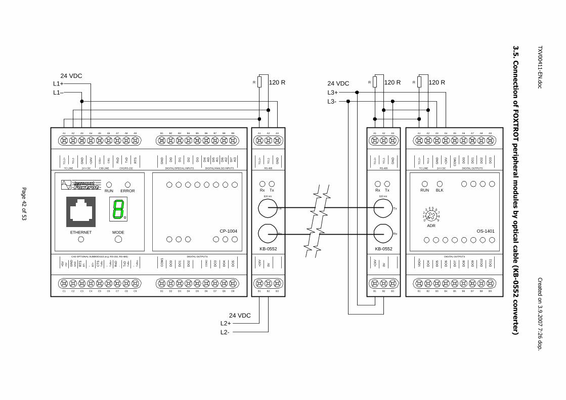
TXV00411-EN.doc
Created on 3.9.2007 7:26 dop.
Page 42 of 53
3.5
. Connectio
n o
f FO
XTR
OT p
erip
hera
l module
s b
y o
ptic
al c
able
(KB-0
552 c
onverte
r)
A1 A2 A3 A4 A5 A6 A7 A8 A9
C1 C2 C3 C4 C5 C6 C7 C8 C9
B1 B2 B3 B4 B5 B6 B7 B8 B9
D1 D2 D3 D4 D5 D6 D7 D8 D9
CP-1004
RUN ERROR
ETHERNET MODE
TC
L2+
TC
L2-
GN
D
+24
V
CIB
1+
CIB
1-
TxD
RxD
RT
S
TC LINE 24 V DC CIB LINE CH1/RS-232
CO
M1
DO
0
DO
1
DO
2
CO
M2
DO
3
DO
4
DO
5
DIGITAL OUTPUTS
GN
D
DI0
DI1
DI2
DI3
DI4
DIGITAL/SPECIAL INPUTS DIGITAL/ANALOG INPUTS
AI0
DI5
AI1
DI6
AI2
DI7
AI3
+5V
CH2 OPTIONAL SUBMODULE (e.g. RS-232, RS-485)
+5V GN
DG
ND
RT
SB
T- - BT
+
CT
ST
xRx-
- TxR
x+
RxD
- TxD
TxR
x-
- TxR
x+
L1+
L2+
L3+L1–
L2-
L3-
24 VDC
24 VDC
24 VDC
A1 A2 A3 A4 A5 A6 A7 A8 A9
B1 B2 B3 B4 B5 B6 B7 B8 B9
VD
O+
DO
4
DO
5
DO
6
DO
7
DO
8
DO
9
DO
10
DO
11
TC
L2+
TC
L2-
GN
D
+24
V
CO
M1
DO
0
DO
1
DO
2
DO
3
TC LINE 24 V DC DIGITAL OUTPUTS
DIGITAL OUTPUTS
OS-1401ADR
012
3 4 5 6789
RUN BLK
RR R 120 R120 R 120 R
A1 A2 A3
B1 B2 B3
TC
L2+
TC
L2-
GN
D
RS-485
+24
V
0V
KB-0552
Rx Tx
Tx
Rx
820 nm
A1 A2 A3
B1 B2 B3
TC
L2+
TC
L2-
GN
D
RS-485
+24
V
0V
KB-0552
Rx Tx
Tx
Rx
820 nm
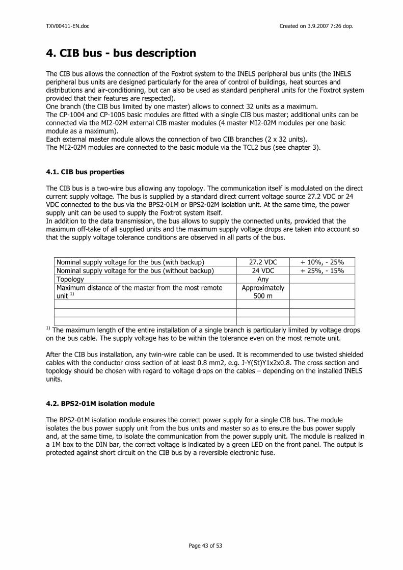
TXV00411-EN.doc Created on 3.9.2007 7:26 dop.
Page 43 of 53
4. CIB bus - bus description The CIB bus allows the connection of the Foxtrot system to the INELS peripheral bus units (the INELS peripheral bus units are designed particularly for the area of control of buildings, heat sources and distributions and air-conditioning, but can also be used as standard peripheral units for the Foxtrot system provided that their features are respected). One branch (the CIB bus limited by one master) allows to connect 32 units as a maximum. The CP-1004 and CP-1005 basic modules are fitted with a single CIB bus master; additional units can be connected via the MI2-02M external CIB master modules (4 master MI2-02M modules per one basic module as a maximum). Each external master module allows the connection of two CIB branches (2 x 32 units). The MI2-02M modules are connected to the basic module via the TCL2 bus (see chapter 3). 4.1. CIB bus properties
The CIB bus is a two-wire bus allowing any topology. The communication itself is modulated on the direct current supply voltage. The bus is supplied by a standard direct current voltage source 27.2 VDC or 24 VDC connected to the bus via the BPS2-01M or BPS2-02M isolation unit. At the same time, the power supply unit can be used to supply the Foxtrot system itself. In addition to the data transmission, the bus allows to supply the connected units, provided that the maximum off-take of all supplied units and the maximum supply voltage drops are taken into account so that the supply voltage tolerance conditions are observed in all parts of the bus.
Nominal supply voltage for the bus (with backup) 27.2 VDC + 10%, - 25% Nominal supply voltage for the bus (without backup) 24 VDC + 25%, - 15% Topology Any Maximum distance of the master from the most remote unit 1)
Approximately 500 m
1) The maximum length of the entire installation of a single branch is particularly limited by voltage drops on the bus cable. The supply voltage has to be within the tolerance even on the most remote unit. After the CIB bus installation, any twin-wire cable can be used. It is recommended to use twisted shielded cables with the conductor cross section of at least 0.8 mm2, e.g. J-Y(St)Y1x2x0.8. The cross section and topology should be chosen with regard to voltage drops on the cables – depending on the installed INELS units. 4.2. BPS2-01M isolation module The BPS2-01M isolation module ensures the correct power supply for a single CIB bus. The module isolates the bus power supply unit from the bus units and master so as to ensure the bus power supply and, at the same time, to isolate the communication from the power supply unit. The module is realized in a 1M box to the DIN bar, the correct voltage is indicated by a green LED on the front panel. The output is protected against short circuit on the CIB bus by a reversible electronic fuse.
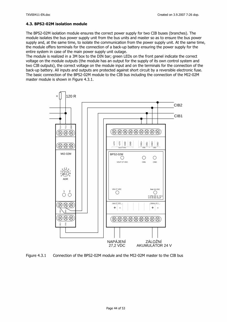
TXV00411-EN.doc Created on 3.9.2007 7:26 dop.
Page 44 of 53
4.3. BPS2-02M isolation module
The BPS2-02M isolation module ensures the correct power supply for two CIB buses (branches). The module isolates the bus power supply unit from the bus units and master so as to ensure the bus power supply and, at the same time, to isolate the communication from the power supply unit. At the same time, the module offers terminals for the connection of a back-up battery ensuring the power supply for the entire system in case of the main power supply unit outage. The module is realized in a 3M box to the DIN bar; green LEDs on the front panel indicate the correct voltage on the module outputs (the module has an output for the supply of its own control system and two CIB outputs), the correct voltage on the module input and on the terminals for the connection of the back-up battery. All inputs and outputs are protected against short circuit by a reversible electronic fuse. The basic connection of the BPS2-02M module to the CIB bus including the connection of the MI2-02M master module is shown in Figure 4.3.1.
R 120 R
CIB
2+C
IB1+
TC
L2+
CIB
2-C
IB1-
TC
L2-
GN
D
MI2-02M
1 2
ADR0
12
3 4 5 6789
R
BPS2-02MC
IB2-
CIB
2+
CIB
1-
CIB
1+
+27V
GN
D
+27V
GN
D
+ - + -input 27 VDC Battery 24 V
CIB2CIB1Out 27 VDC
VOUT 27 VDC CIB1 CIB2
VIN 27 VDC Batt 24 VDC
CIB1
CIB2
ZÁLOŽNÍ AKUMULÁTOR 24 V
NAPÁJENÍ 27,2 VDC
Figure 4.3.1 Connection of the BPS2-02M module and the MI2-02M master to the CIB bus
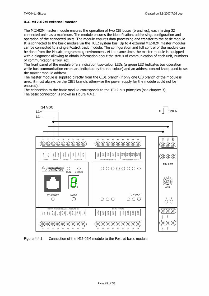
TXV00411-EN.doc Created on 3.9.2007 7:26 dop.
Page 45 of 53
4.4. MI2-02M external master
The MI2-02M master module ensures the operation of two CIB buses (branches), each having 32 connected units as a maximum. The module ensures the identification, addressing, configuration and operation of the connected units. The module ensures data processing and transfer to the basic module. It is connected to the basic module via the TCL2 system bus. Up to 4 external MI2-02M master modules can be connected to a single Foxtrot basic module. The configuration and full control of the module can be done from the Mosaic programming environment. At the same time, the master module is equipped with a diagnostic allowing to obtain information about the status of communication of each unit, numbers of communication errors, etc. The front panel of the module offers indication two-colour LEDs (a green LED indicates bus operation while bus communication errors are indicated by the red colour) and an address control knob, used to set the master module address. The master module is supplied directly from the CIB1 branch (if only one CIB branch of the module is used, it must always be the CIB1 branch, otherwise the power supply for the module could not be ensured). The connection to the basic module corresponds to the TCL2 bus principles (see chapter 3). The basic connection is shown in Figure 4.4.1.
A1 A2 A3 A4 A5 A6 A7 A8 A9
C1 C2 C3 C4 C5 C6 C7 C8 C9
B1 B2 B3 B4 B5 B6 B7 B8 B9
D1 D2 D3 D4 D5 D6 D7 D8 D9
CP-1004
RUN ERROR
ETHERNET MODE
TC
L2+
TC
L2-
GN
D
+24
V
CIB
1+
CIB
1-
TxD
RxD
RT
S
TC LINE 24 V DC CIB LINE CH1/RS-232
CO
M1
DO
0
DO
1
DO
2
CO
M2
DO
3
DO
4
DO
5
DIGITAL OUTPUTS
GN
D
DI0
DI1
DI2
DI3
DI4
DIGITAL/SPECIAL INPUTS DIGITAL/ANALOG INPUTS
AI0
DI5
AI1
DI6
AI2
DI7
AI3
+5V
CH2 OPTIONAL SUBMODULE (e.g. RS-232, RS-485)
+5V GN
DG
ND
RT
SB
T- - BT
+
CT
ST
xRx-
- TxR
x+
RxD
- TxD
TxR
x-
- TxR
x+
L1+L1-
24 VDCR 120 R
CIB
2+
CIB
1+T
CL2
+
CIB
2-
CIB
1-T
CL2
-
GN
D
MI2-02M
1 2
ADR0
12
3 4 5 6789
Figure 4.4.1. Connection of the MI2-02M module to the Foxtrot basic module
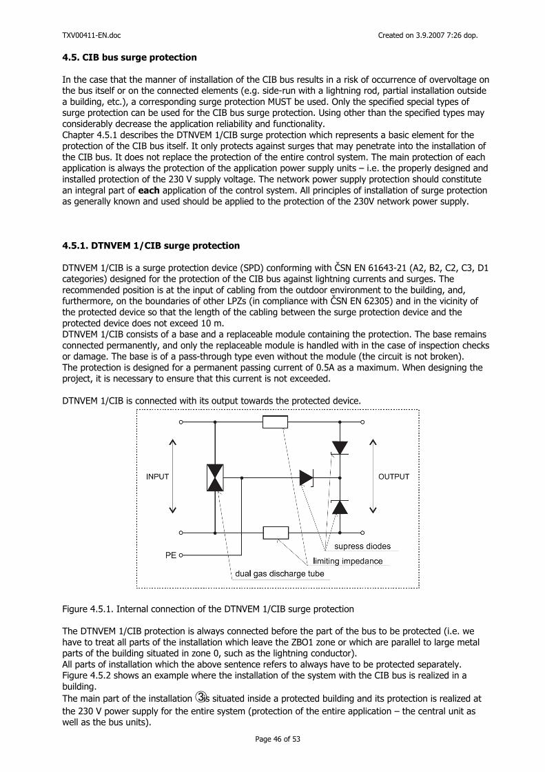
TXV00411-EN.doc Created on 3.9.2007 7:26 dop.
Page 46 of 53
4.5. CIB bus surge protection
In the case that the manner of installation of the CIB bus results in a risk of occurrence of overvoltage on the bus itself or on the connected elements (e.g. side-run with a lightning rod, partial installation outside a building, etc.), a corresponding surge protection MUST be used. Only the specified special types of surge protection can be used for the CIB bus surge protection. Using other than the specified types may considerably decrease the application reliability and functionality. Chapter 4.5.1 describes the DTNVEM 1/CIB surge protection which represents a basic element for the protection of the CIB bus itself. It only protects against surges that may penetrate into the installation of the CIB bus. It does not replace the protection of the entire control system. The main protection of each application is always the protection of the application power supply units – i.e. the properly designed and installed protection of the 230 V supply voltage. The network power supply protection should constitute an integral part of each application of the control system. All principles of installation of surge protection as generally known and used should be applied to the protection of the 230V network power supply. 4.5.1. DTNVEM 1/CIB surge protection
DTNVEM 1/CIB is a surge protection device (SPD) conforming with ČSN EN 61643-21 (A2, B2, C2, C3, D1 categories) designed for the protection of the CIB bus against lightning currents and surges. The recommended position is at the input of cabling from the outdoor environment to the building, and, furthermore, on the boundaries of other LPZs (in compliance with ČSN EN 62305) and in the vicinity of the protected device so that the length of the cabling between the surge protection device and the protected device does not exceed 10 m. DTNVEM 1/CIB consists of a base and a replaceable module containing the protection. The base remains connected permanently, and only the replaceable module is handled with in the case of inspection checks or damage. The base is of a pass-through type even without the module (the circuit is not broken). The protection is designed for a permanent passing current of 0.5A as a maximum. When designing the project, it is necessary to ensure that this current is not exceeded. DTNVEM 1/CIB is connected with its output towards the protected device.
Figure 4.5.1. Internal connection of the DTNVEM 1/CIB surge protection The DTNVEM 1/CIB protection is always connected before the part of the bus to be protected (i.e. we have to treat all parts of the installation which leave the ZBO1 zone or which are parallel to large metal parts of the building situated in zone 0, such as the lightning conductor). All parts of installation which the above sentence refers to always have to be protected separately. Figure 4.5.2 shows an example where the installation of the system with the CIB bus is realized in a building. The main part of the installation ③ is situated inside a protected building and its protection is realized at the 230 V power supply for the entire system (protection of the entire application – the central unit as well as the bus units).
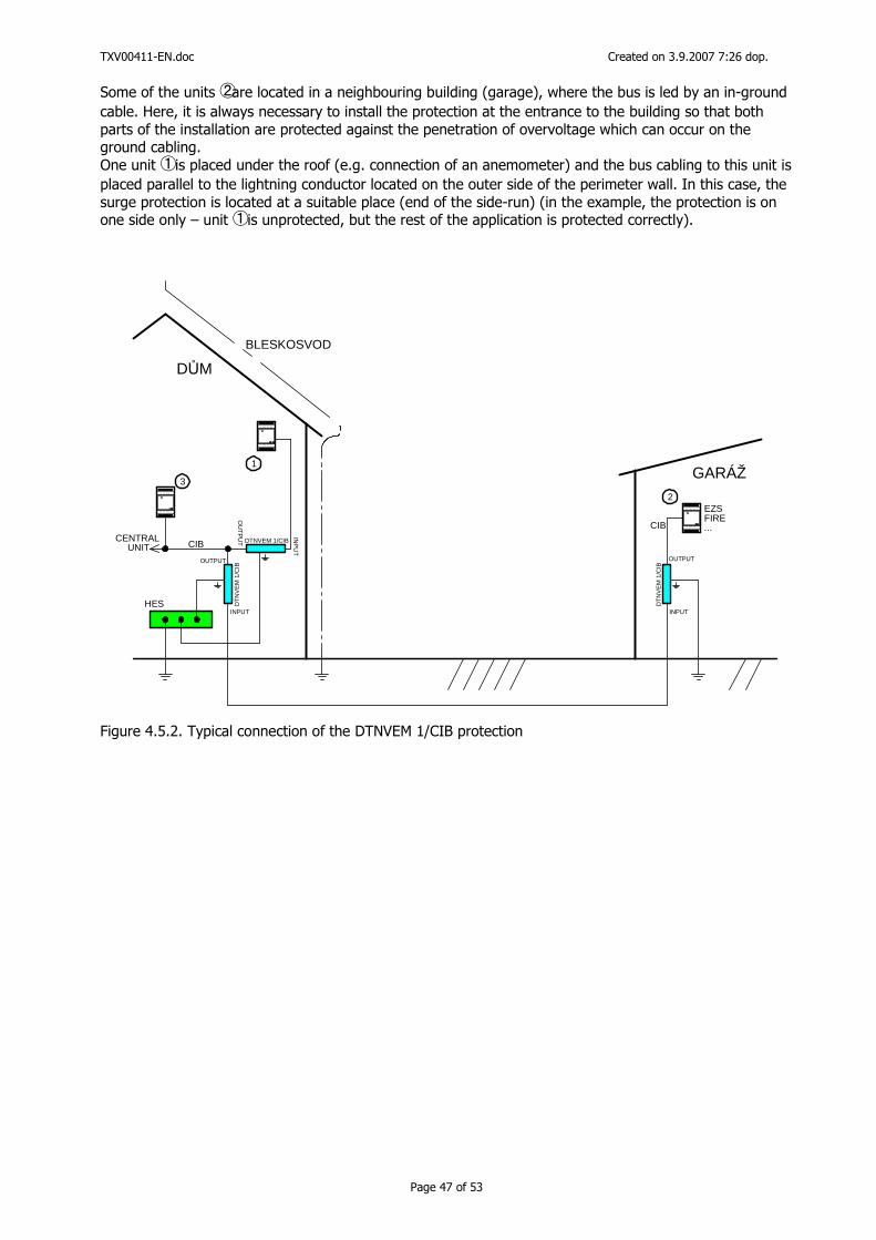
TXV00411-EN.doc Created on 3.9.2007 7:26 dop.
Page 47 of 53
Some of the units ② are located in a neighbouring building (garage), where the bus is led by an in-ground cable. Here, it is always necessary to install the protection at the entrance to the building so that both parts of the installation are protected against the penetration of overvoltage which can occur on the ground cabling. One unit ① is placed under the roof (e.g. connection of an anemometer) and the bus cabling to this unit is placed parallel to the lightning conductor located on the outer side of the perimeter wall. In this case, the surge protection is located at a suitable place (end of the side-run) (in the example, the protection is on one side only – unit ① is unprotected, but the rest of the application is protected correctly).
DŮM
GARÁŽ
BLESKOSVOD
DT
NV
EM
1/C
IB
DTNVEM 1/CIB
DT
NV
EM
1/C
IB
INPUT
INP
UT
INPUT
OUTPUT
OU
TP
UT
OUTPUT
CIB R
I M2-140M
VOUT 27 VDC
R
IM2-140M
VOUT 27 VDC
R
IM2-140M
VO UT 2 7 VDC
EZSFIRE...
CIB
1
3
2
HES
CENTRAL UNIT
Figure 4.5.2. Typical connection of the DTNVEM 1/CIB protection
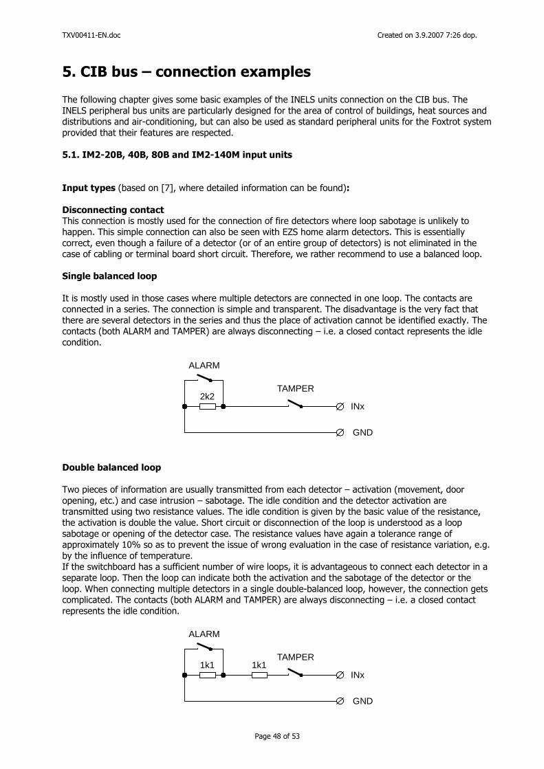
TXV00411-EN.doc Created on 3.9.2007 7:26 dop.
Page 48 of 53
5. CIB bus – connection examples The following chapter gives some basic examples of the INELS units connection on the CIB bus. The INELS peripheral bus units are particularly designed for the area of control of buildings, heat sources and distributions and air-conditioning, but can also be used as standard peripheral units for the Foxtrot system provided that their features are respected. 5.1. IM2-20B, 40B, 80B and IM2-140M input units
Input types (based on [7], where detailed information can be found): Disconnecting contact This connection is mostly used for the connection of fire detectors where loop sabotage is unlikely to happen. This simple connection can also be seen with EZS home alarm detectors. This is essentially correct, even though a failure of a detector (or of an entire group of detectors) is not eliminated in the case of cabling or terminal board short circuit. Therefore, we rather recommend to use a balanced loop. Single balanced loop
It is mostly used in those cases where multiple detectors are connected in one loop. The contacts are connected in a series. The connection is simple and transparent. The disadvantage is the very fact that there are several detectors in the series and thus the place of activation cannot be identified exactly. The contacts (both ALARM and TAMPER) are always disconnecting – i.e. a closed contact represents the idle condition.
2k2
ALARM
TAMPER
INx
GND
Double balanced loop
Two pieces of information are usually transmitted from each detector – activation (movement, door opening, etc.) and case intrusion – sabotage. The idle condition and the detector activation are transmitted using two resistance values. The idle condition is given by the basic value of the resistance, the activation is double the value. Short circuit or disconnection of the loop is understood as a loop sabotage or opening of the detector case. The resistance values have again a tolerance range of approximately 10% so as to prevent the issue of wrong evaluation in the case of resistance variation, e.g. by the influence of temperature. If the switchboard has a sufficient number of wire loops, it is advantageous to connect each detector in a separate loop. Then the loop can indicate both the activation and the sabotage of the detector or the loop. When connecting multiple detectors in a single double-balanced loop, however, the connection gets complicated. The contacts (both ALARM and TAMPER) are always disconnecting – i.e. a closed contact represents the idle condition.
1k1 1k1
ALARM
TAMPER
INx
GND
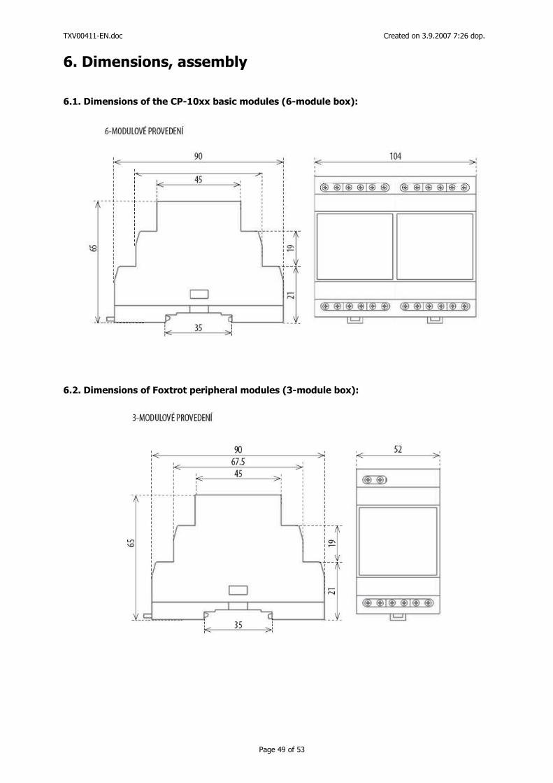
TXV00411-EN.doc Created on 3.9.2007 7:26 dop.
Page 49 of 53
6. Dimensions, assembly 6.1. Dimensions of the CP-10xx basic modules (6-module box):
6.2. Dimensions of Foxtrot peripheral modules (3-module box):
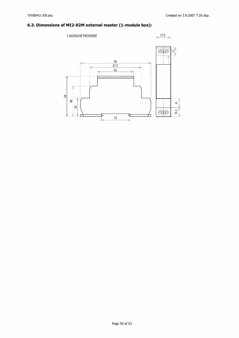
TXV00411-EN.doc Created on 3.9.2007 7:26 dop.
Page 50 of 53
6.3. Dimensions of MI2-02M external master (1-module box):
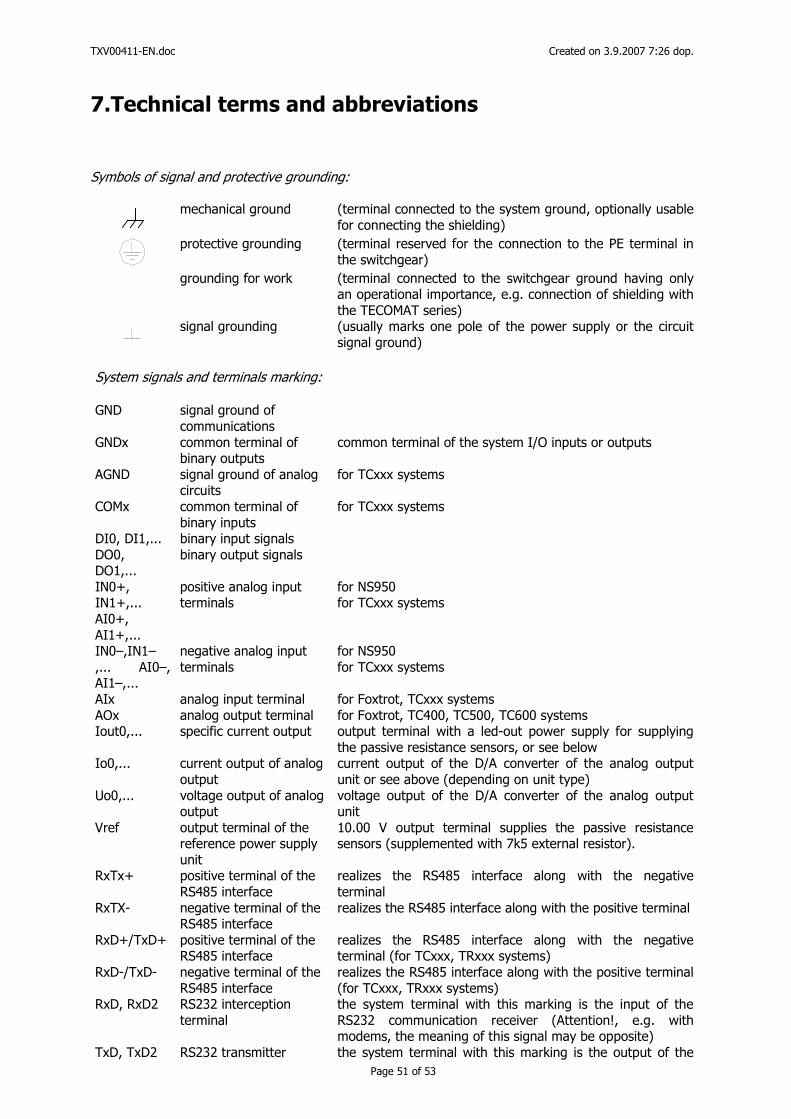
TXV00411-EN.doc Created on 3.9.2007 7:26 dop.
Page 51 of 53
7.Technical terms and abbreviations
Symbols of signal and protective grounding:
mechanical ground (terminal connected to the system ground, optionally usable
for connecting the shielding)
protective grounding (terminal reserved for the connection to the PE terminal in
the switchgear)
grounding for work (terminal connected to the switchgear ground having only
an operational importance, e.g. connection of shielding with the TECOMAT series)
signal grounding (usually marks one pole of the power supply or the circuit
signal ground) System signals and terminals marking: GND signal ground of
communications
GNDx common terminal of binary outputs
common terminal of the system I/O inputs or outputs
AGND signal ground of analog circuits
for TCxxx systems
COMx common terminal of binary inputs
for TCxxx systems
DI0, DI1,... binary input signals DO0, DO1,...
binary output signals
IN0+, IN1+,... AI0+, AI1+,...
positive analog input terminals
for NS950 for TCxxx systems
IN0–,IN1–,... AI0–, AI1–,...
negative analog input terminals
for NS950 for TCxxx systems
AIx analog input terminal for Foxtrot, TCxxx systems AOx analog output terminal for Foxtrot, TC400, TC500, TC600 systems Iout0,... specific current output output terminal with a led-out power supply for supplying
the passive resistance sensors, or see below Io0,... current output of analog
output current output of the D/A converter of the analog output unit or see above (depending on unit type)
Uo0,... voltage output of analog output
voltage output of the D/A converter of the analog output unit
Vref output terminal of the reference power supply unit
10.00 V output terminal supplies the passive resistance sensors (supplemented with 7k5 external resistor).
RxTx+ positive terminal of the RS485 interface
realizes the RS485 interface along with the negative terminal
RxTX- negative terminal of the RS485 interface
realizes the RS485 interface along with the positive terminal
RxD+/TxD+ positive terminal of the RS485 interface
realizes the RS485 interface along with the negative terminal (for TCxxx, TRxxx systems)
RxD-/TxD- negative terminal of the RS485 interface
realizes the RS485 interface along with the positive terminal (for TCxxx, TRxxx systems)
RxD, RxD2 RS232 interception terminal
the system terminal with this marking is the input of the RS232 communication receiver (Attention!, e.g. with modems, the meaning of this signal may be opposite)
TxD, TxD2 RS232 transmitter the system terminal with this marking is the output of the
TXV00411-EN.doc Created on 3.9.2007 7:26 dop.
Page 52 of 53
terminal RS232 communication transmitter (Attention!, e.g. with modems, the meaning of this signal may be opposite)
RTS, RTS2 RS232 direction control terminal
the system terminal with this marking is the output for the RS232 communication direction control (Attention!, e.g. with modems, the meaning of this signal may be opposite)
232DIS TC400, TC500, TC600 service terminal
signal for switching the communication inside TC400, TC500, TC600, TR050, TR200, TR300, must be connected according to the documentation
24V~ TC400, TC500, TC600 and TRxxx power supply terminals
terminals for connecting the system power supply (independent of polarity)
24V= TC700 power supply terminals
terminals for connecting the system power supply
+USS binary units power supply
the positive pole of the binary circuits power supply is connected to the terminal with this marking (DC units)
–USS binary units power supply
the negative pole of the binary circuits power supply is connected to the terminal with this marking (DC units)
UST binary units power supply
one pole of the binary circuits power supply is connected to the terminal with this marking (AC units)
Abbreviations, symbols:
CIB Twin-wire bus manufactured by Teco a. s. for the connection of INELS units TCL2 System communication bus for the connection of peripheral and special modules of the Foxtrot
system (works with the RS-485 physical interface) LCH Logical channel realized on the Ethernet interface (multiple communication channels marked
LCH1 to LCHx can be realized simultaneously on one physical Ethernet interface) TCxxx TC400, TC500, TC600, TC700 and other PLC systems. TRxxx TR050, TR200, TR300 regulation systems, power supply and communication interface of the
TR341 and TR101 modules. PLC Programmable control system (also programmable logic controller), control system for general
use of technology control; at the same time, the TECOMAT series manufactured by Teco a. s. offers many functions and system support for the use in measurement and regulation applications.
JTS Unified telephone network, i.e. the general public telephone distribution; connection to JTS means connection to the general telephone outlet.
PC Personal computer, IBM PC compatible; in the corporate documentation of Teco a. s., the term computer always implies a personal computer (used for programming of systems, activation, visualization etc.)
OV1000 Resistance transmitter, an abbreviation referring to a resistance transmitter with a nominal resistance of 1000W (connected as a potentiometer, it usually has three terminals - resistance start, slider and resistor end).
Pt100 Passive resistance sensor, an abbreviation referring to a passive resistance sensor with a resistance of 100W at 0 °C, with platinum as the basic production material (typical industrial use in temperatures up to 850 °C).
Ni1000 Passive resistance sensor, an abbreviation referring to a passive resistance sensor with a resistance of 1000W at 0 °C, with nickel as the basic production material (typical use in the area of measurement and regulation, typically suitable for temperature measurements up to 180 °C).

TXV00411-EN.doc Created on 3.9.2007 7:26 dop.
Page 53 of 53
8.References [1] Designer's manual for Tecomat and Tecoreg systems, cat. no. TXV 001 08 [2] Foxtrot programmable logic controllers manual, cat. no. TXV 004 10 [3] Serial communication of Tecomat systems manual, cat. no. TXV 004 03 [4] MR-0104 submodule description manual, cat. no. TXV 101 04. [5] MR-0114 submodule description manual, cat. no. TXV 101 14. [6] MR-0124 submodule description manual, cat. no. TXV 101 24. [7] Jablotron company documentation.