tx-503 - vectron international · 7fdus oufsob • px pbe • 5 7&$53 • uuq xxx wfduspo dpn...
TRANSCRIPT
Vectron International • 267 Lowell Road, Suite 102, Hudson, NH 03051 • Tel: 1-88-VECTRON-1 • http://www.vectron.comPage 1
TX-503Temperature Compensated Crystal Oscillator
High Precision
• Ultra High Stability TCXO• OCXO Replacement• Low Power Consumption• Meets Stratum 3 acc. GR-1244• ROHS 6 Compliant• Frequency Range1: 8 - 50 MHz• Standard Frequencies : 10, 12.8, 19.2, 20, 22.1184, 25, • 30.72, 40, 50 MHz• Uses Vectron’s Ultra Smooth Compensation (USC) Algorithm• Excellent Phase Noise and Allan Deviation
• 1588 Application• Test Equipment• Femto Base Station• Communication Equipment
Features Applications
TX-503
Performance Specifications
Frequency Stabilities1, 3 (Standard - 8 to 26 MHz)
Parameter Min Typical Max Units Condition2
vs. operating temperature range referenced to (dFmax+dFmin)/2
-50-30
+50+30
ppbppb
-40 to +85°C-20 to +70°C
Opt
ions
3
In a 24h period at constant temperature
-5 +5 ppb after 7 days of continous operation
Frequency vs. temperature slope -5 +5 ppb/°C
Initial tolerance vs. supply voltage changevs. load changevs. aging / 1. yearvs. aging / 10 years
-0.5-10-10-1.0-3.0
+0.5+10+10+1.0+3.0
ppmppbppbppmppm
VS ±5% staticLoad ±10% static
after 30 days of operationafter 30 days of operation

Vectron International • 267 Lowell Road, Suite 102, Hudson, NH 03051 • Tel: 1-88-VECTRON-1 • http://www.vectron.comPage 2
Performance Specifications
Supply Voltage (Vs)
Parameter Min Typical Max Units Condition2
Supply Voltage (standard) 3.135 3.3 3.465 V8 - 50MHz
Current Consumption 12 mA
Supply Voltage (Option) 4.75 5 5.25 V
Current Consumption 8 mA
RF Output
Signal [standard] HCMOS
Load 15 pF
Signal Level (Vol) 0.3 V
Signal Level (Voh) 2.6 V
Duty Cycle 40 60 % @ Vs/2
Rise and Fall time 5 ns 10 to 90 %
Frequency Tuning (EFC) 8 to 26 MHzTuning Range Fixed TCXO; No adjust
Opt
ion3
Tuning Range ±3.5 +10 ppm
Linearity 10 %
Tuning Slope Positive
Control Input Impedance >100 kOhm
Control Voltage (Vc) Range 0.0 1.65 3.3 V @ 3.3V
0.5 2.5 4.5 V @ 5V
Additional Parameters
Phase Noise4
-65-93
-118-140-154-156
dBc/HzdBc/HzdBc/HzdBc/HzdBc/HzdBc/Hz
1 Hz10 Hz
100 Hz1 kHz
10 kHz100 kHz
Jitter 0.2 ps RMS @ 10 kHz to 5 MHz
ADEV 80 E-12 @ 1sec.
80 E-12 @10sec
Weight 2.0 g
Processing & Packing Handling & Processing Note
Reflow Profile IPC / JEDEC J-STD-020 (latest version)
Absolute Maximum Ratings
Supply Voltage (Vs) -0.6 6.0 V
Output Load 50 pF
Operable Temperature Range -40 +85 °C
Storage Temperature Range -40 +90 °C
Environmental ConditionsRapid Temperature Changes MIL-883-1010 Cond B 500 cycles -55/125C
Vibration MIL-STD-883 Meth 2007 Cond A 20G 20-2000Hz 4x in each 3axis 4 minShock MIL-STD-202 Meth 213B Cond. F; 1500g 0,5ms 6 shocks in each direction
Solderability J_STD_002C Cond A, Through hole device/ Cond. B, SMD 255C (diving time 50,5sec.) Dip+Look with 8h damp pre-treatment: solder wetting >95%
Solvent Resistance MIL-STD-883 Meth 2015 Solv. 1,3,4
ESD JESD22-A114F Class 1B; 10* 2000V
Moisture Sensitivity Level 1 JESD22-A113-B
RoHS Compliance 100% ROHS Compliant

Vectron International • 267 Lowell Road, Suite 102, Hudson, NH 03051 • Tel: 1-88-VECTRON-1 • http://www.vectron.comPage 3
TX-503Height “H” Pin Length “L”
3.8 NA
Pin Connections1 Control Voltage Input (Vc) / N.C.
2 Enable / N.C.
3 Ground (Case)
4 RF-Output
5 N.C.
6 Supply Voltage Input (Vs)
Dimensions in mm
Outline Drawing / Enclosure
Enable true table (optional): TX-503Pin 2 Pin 4
High Data
Open Data
Low High Tristate

Vectron International • 267 Lowell Road, Suite 102, Hudson, NH 03051 • Tel: 1-88-VECTRON-1 • http://www.vectron.comPage 4
TDEV-without filter ADEV
Performance Data
Temperature Stability Phase Noise4
Vectron International • 267 Lowell Road, Suite 102, Hudson, NH 03051 • Tel: 1-88-VECTRON-1 • http://www.vectron.comPage 5
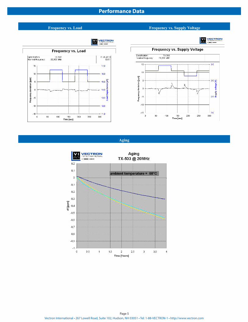
Performance Data
Frequency vs. Load Frequency vs. Supply Voltage
Aging

Vectron International • 267 Lowell Road, Suite 102, Hudson, NH 03051 • Tel: 1-88-VECTRON-1 • http://www.vectron.comPage 6
Recommended Reflow Profile
Profile Feature Pb-Free Assembly/Sn-Pb Assembly
Profile Feature Pb-Free Assembly/Sn-Pb Assembly
Average ramp-up rate (TL to TP) 3°C/second max. Time 25°C to Peak Temperature 8 minutes max.
Preheat -Temperature Min TSmin -Temperature Min TSmax
-Time (min to max) tS
150°C200°C
60-180 seconds
Time maintained above-Temperature (TL)
-Time (tL)217°C
60-150 seconds
TSmax to TL -Ramp-up Rate 3°C/second max
Time maintained above-Temperature (TL)
-Time (tL)217°C
60-150 secondsTime within 5°C of actual Peak
Temperature (tP)20-40 seconds
Peak Temperature (TP) max 260°C Ramp-down Rate 6°C/ second max
Note: All temperatures refer to topside of the package, measured on the package body surface.SMD oscillators must be on the top side of the PCB during the reflow process.
Standard Shipping Method (TX-503)
Enclosure Type Tape Width W (mm) Quantity per meter Quantity per reel Dimension P
G287 24 83,3 850 12

Vectron International • 267 Lowell Road, Suite 102, Hudson, NH 03051 • Tel: 1-88-VECTRON-1 • http://www.vectron.comPage 7
Ordering Information1,3
TX - 503 0 - E A J - 308 0 - 10M0000000
Product FamilyTX: TCXO
PackageHigh PrecisionTCXO SMD version: 503
Height0: 3.8 mm
Supply VoltageD: 5VE: 3.3V
Stability Code308: ± 30 ppb508: ± 50 ppb708: ± 70 ppb107: ±100 ppb
Frequency
Frequency Control0: No Tuning1: ±3.5 ppm2: Enable3: ±3.5 ppm; Enable
DisclaimerVectron International reserves the right to make changes to the product(s) and or information contained herein without notice. No liability is assumed as a result of their use or application. No rights under any patent accompany the sale of any such product(s) or information. Rev: 08/2017
For Additional Information, Please Contact USA:
Vectron International267 Lowell Road, Suite 102
Hudson, NH 03051Tel: 1.888.328.7661Fax: 1.888.329.8328
Europe:Vectron InternationalLandstrasse, D-74924
Neckarbischofsheim, GermanyTel: +49 (0) 7268.801.100Fax: +49 (0) 7268.801.282
Asia:Vectron International
68 Yin Cheng Road(C), 22nd FloorOne LuJiaZui
Pudong, Shanghai 200120, ChinaTel: +86 21 6194 6886Fax: +86 21 6194 6699
RF Output CodeA: HCMOS Temperature Range
J: -20°C to +70°CE: -40°C to +85°C
Notes:1. Contact factory for other frequencies. Not all options and codes are available at all frequencies. 2. Unless otherwise stated conditions are valid at F=20MHz; Vs=3.3V; Vc=1.65; T=25°C; Output Signal=HCMOS; load=15pF3. Contact factory for availability.4. Phase noise degrades with increasing output frequency. Subject to technical modification.