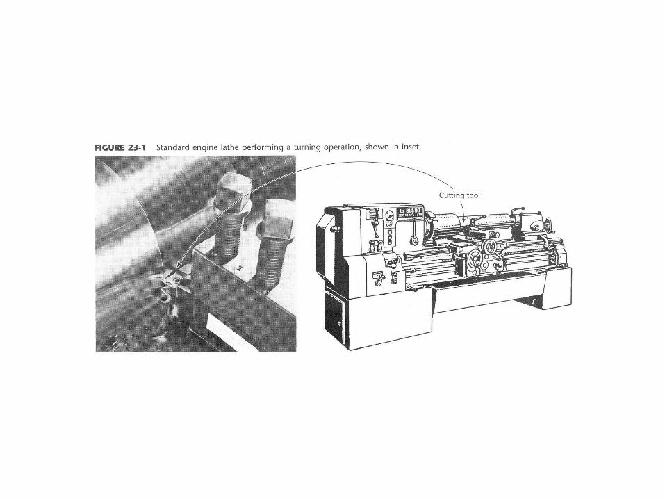
turning boring -...
TRANSCRIPT
TURNING – BORING
TURNING: Machining external cylindrical and conical surfaces.
Work spins and the single cutting tool does the cutting.
Done in Lathe.
Single point tool, longitudinal feed.
FACING: Single point tool, radial feed.
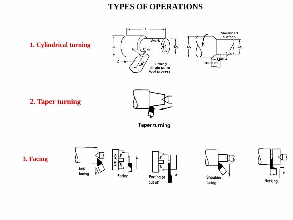
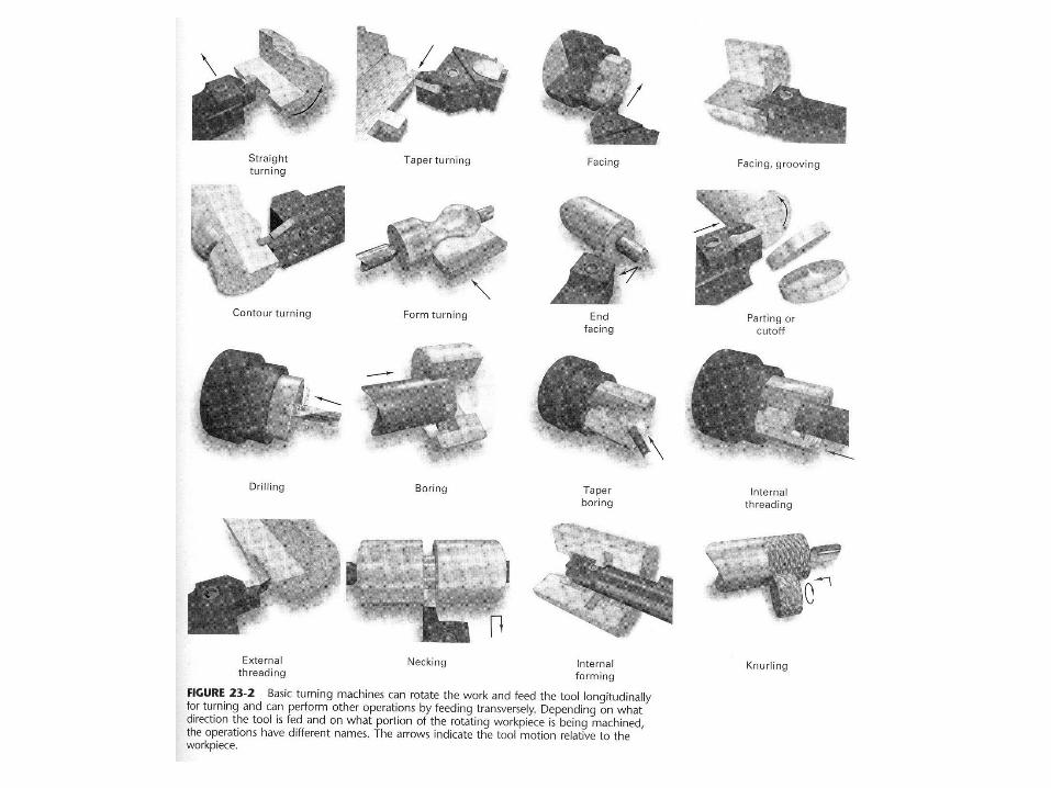
1. Cylindrical turning
2. Taper turning
3. Facing
TYPES OF OPERATIONS
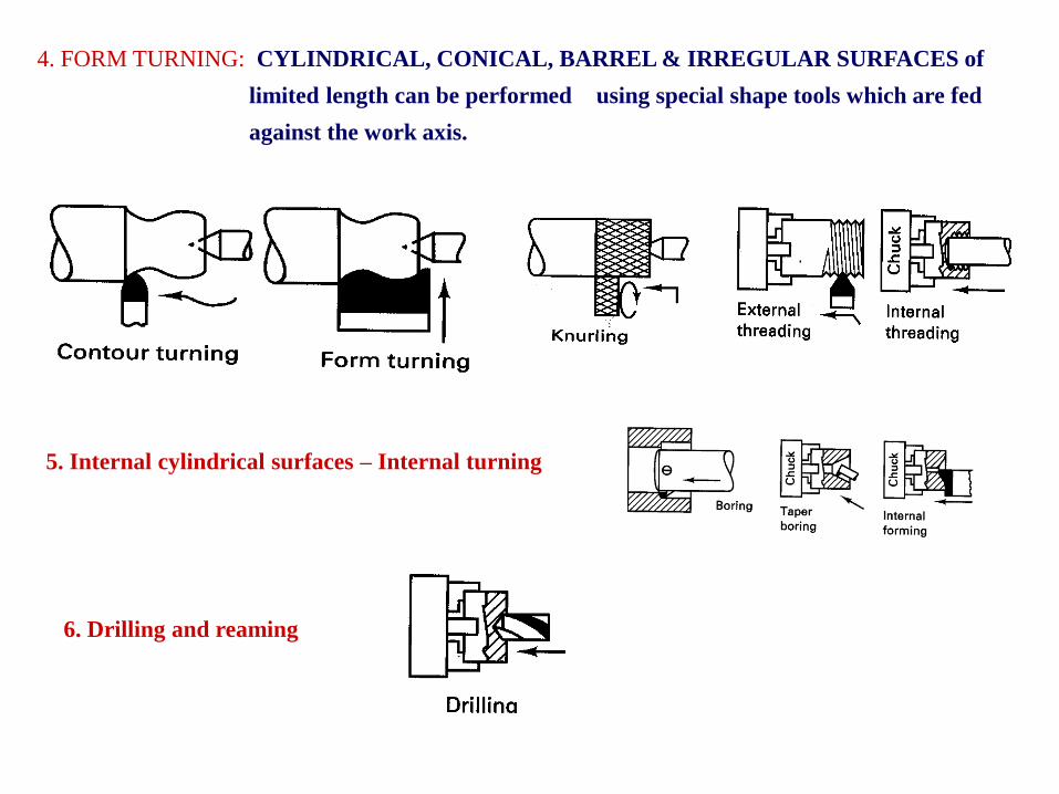
4. FORM TURNING: CYLINDRICAL, CONICAL, BARREL & IRREGULAR SURFACES of
limited length can be performed using special shape tools which are fed
against the work axis.
5. Internal cylindrical surfaces – Internal turning
6. Drilling and reaming
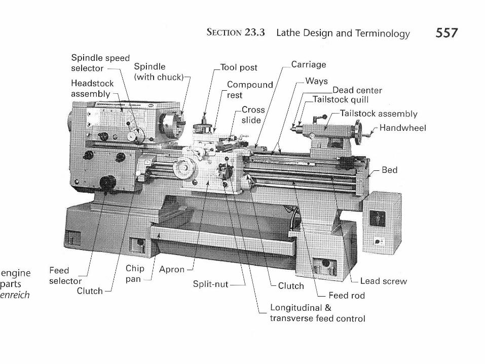
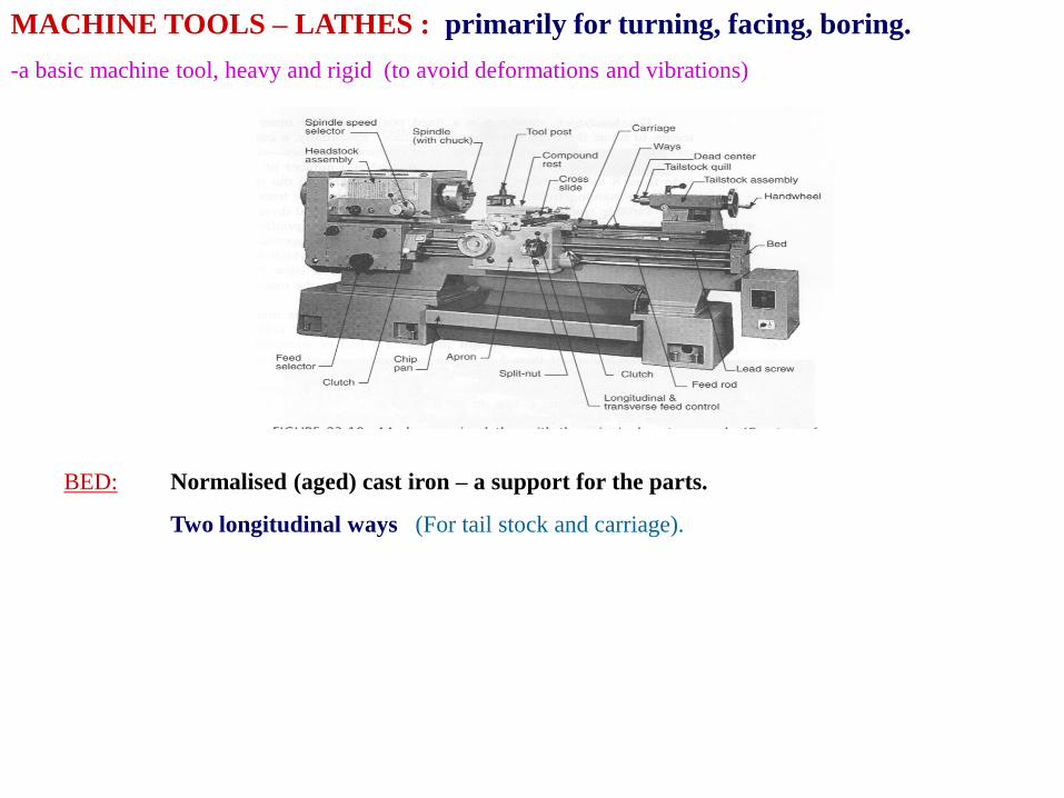
MACHINE TOOLS – LATHES : primarily for turning, facing, boring.
-a basic machine tool, heavy and rigid (to avoid deformations and vibrations)
BED: Normalised (aged) cast iron – a support for the parts.
Two longitudinal ways (For tail stock and carriage).
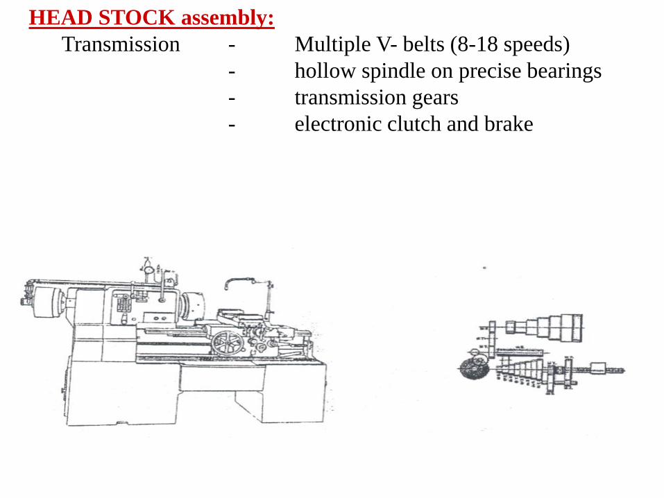
HEAD STOCK assembly:
Transmission - Multiple V- belts (8-18 speeds)
- hollow spindle on precise bearings
- transmission gears
- electronic clutch and brake
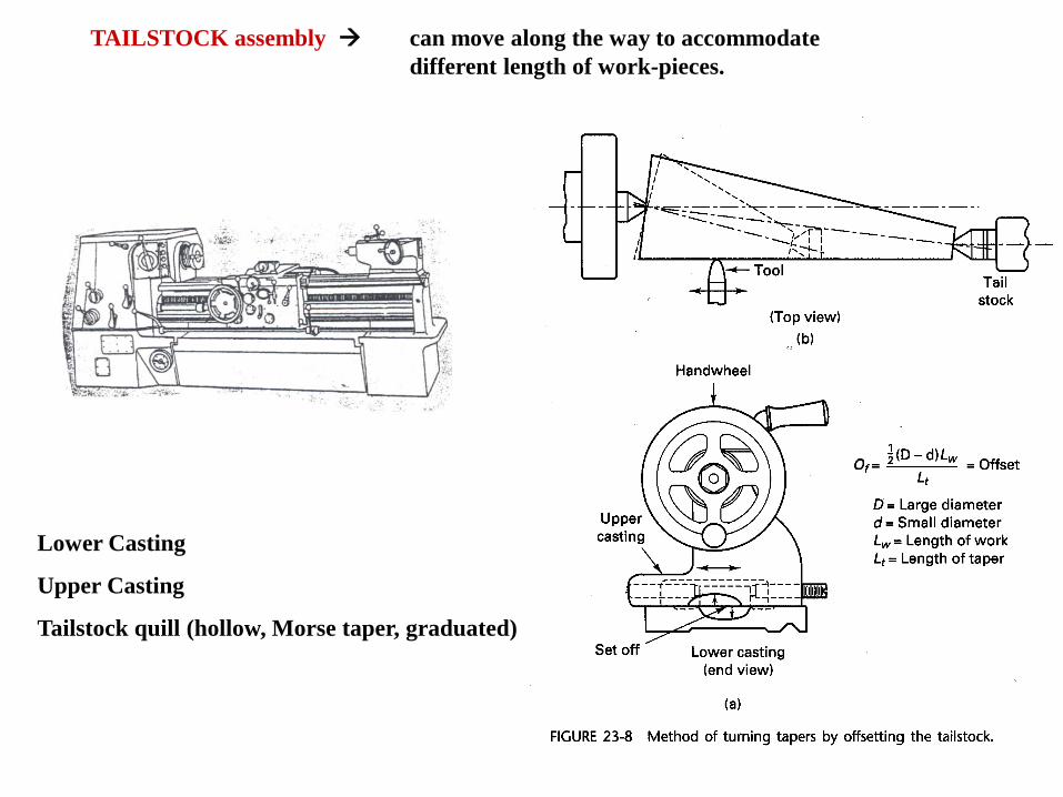
TAILSTOCK assembly can move along the way to accommodate
different length of work-pieces.
Lower Casting
Upper Casting
Tailstock quill (hollow, Morse taper, graduated)
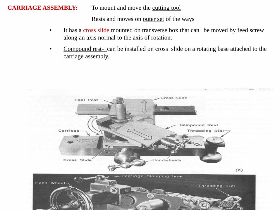
CARRIAGE ASSEMBLY: To mount and move the cutting tool
Rests and moves on outer set of the ways
• It has a cross slide mounted on transverse box that can be moved by feed screw
along an axis normal to the axis of rotation.
• Compound rest- can be installed on cross slide on a rotating base attached to the
carriage assembly.
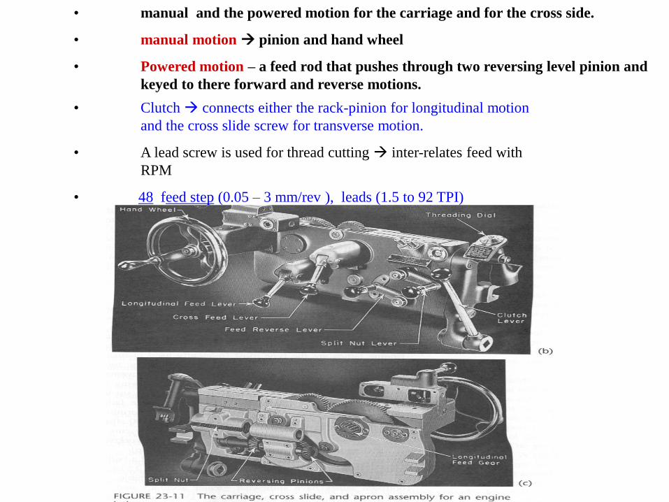
• manual and the powered motion for the carriage and for the cross side.
• manual motion pinion and hand wheel
• Powered motion – a feed rod that pushes through two reversing level pinion and
keyed to there forward and reverse motions.
• Clutch connects either the rack-pinion for longitudinal motion
and the cross slide screw for transverse motion.
• A lead screw is used for thread cutting inter-relates feed with
RPM
• 48 feed step (0.05 – 3 mm/rev ), leads (1.5 to 92 TPI)
SIZES DESIGNATION OF LATHES
1. SWING: Max Dia. Of the job that can be turned, twice of the distance between
the center and nearest point on the ways. 300 mm lathe swing max
dia 300 mm
2. Distance between the centers: maximum length between centers.
3. Size of the hole: Determined by the hollow spindle providing the bar-stock for
machining
TYPES OF LATHES
1. Speed lathes - SIMPLE & LIGHT
- Headstock, tailstock and hand – adjustable cross- slide for tool support on the carriage
- 3-4 speeds up to 4000 RPM
- used for wood turning, polishing and metal spinning
2. Engine lathes - production machine tool, power drive for all the movements.
- many features for controlling the spindle and the feed speed (large no. of speeds and
feeds)
- used in manufacturing – small series
- 12-24” swing and 24 – 28 in size capacity, 50-100HP
- chip panels and cooling system and filters
3. Bench lathes very precise
max swing 10” – same to engine lathes
4. Tool room lathes Universal engine lathes, meant for small parts.
- wider range of speeds and feeds
- designed for greater versatility, greater accuracy
- Shorter and very rigid -> high accuracy
- Have large number of accessories
5. Special purpose lathes extra swing or size capacity
- ex.: for railroad wheel
TURRET LATHES: Automated machines for quantity production
- need non –skilled operators
- turrets are provided with several tools for consecutive operations ( setup in the proper sequence)
high skill to set up the machine is needed
- workpiece, bar-stock that is positioned automatically
Construction * 6-8 sided vertical turret is placed instead of the tail stock – MAIN TURRET
* 4 sided turret is placed instead of the cross slide tool post – AUXILIARY TURRET
* bar stock material feeds the chuck after finishing one piece.
* the turrets can be rotated and indexed and reciprocated along the main axis
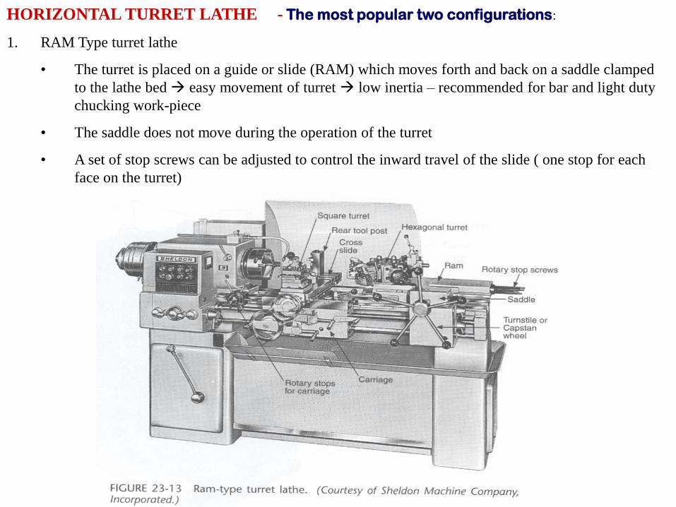
HORIZONTAL TURRET LATHE - The most popular two configurations:
1. RAM Type turret lathe
• The turret is placed on a guide or slide (RAM) which moves forth and back on a saddle clamped
to the lathe bed easy movement of turret low inertia – recommended for bar and light duty
chucking work-piece
• The saddle does not move during the operation of the turret
• A set of stop screws can be adjusted to control the inward travel of the slide ( one stop for each
face on the turret)
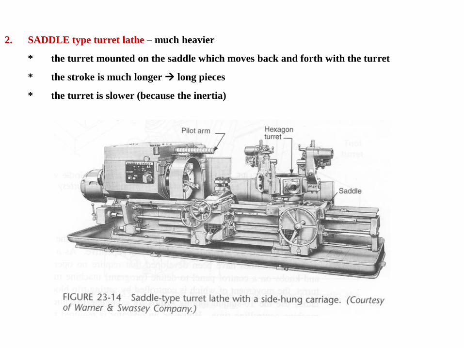
2. SADDLE type turret lathe – much heavier
* the turret mounted on the saddle which moves back and forth with the turret
* the stroke is much longer long pieces
* the turret is slower (because the inertia)
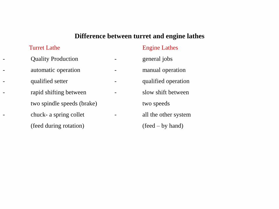
Difference between turret and engine lathes
Turret Lathe Engine Lathes
- Quality Production - general jobs
- automatic operation - manual operation
- qualified setter - qualified operation
- rapid shifting between - slow shift between
two spindle speeds (brake) two speeds
- chuck- a spring collet - all the other system
(feed during rotation) (feed – by hand)
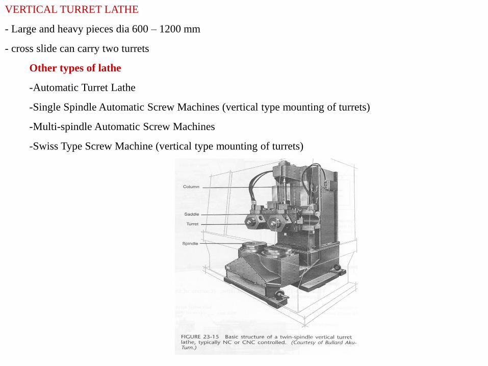
VERTICAL TURRET LATHE
- Large and heavy pieces dia 600 – 1200 mm
- cross slide can carry two turrets
Other types of lathe
-Automatic Turret Lathe
-Single Spindle Automatic Screw Machines (vertical type mounting of turrets)
-Multi-spindle Automatic Screw Machines
-Swiss Type Screw Machine (vertical type mounting of turrets)
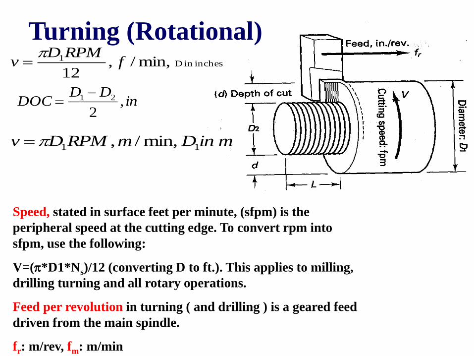
Speed, stated in surface feet per minute, (sfpm) is the
peripheral speed at the cutting edge. To convert rpm into
sfpm, use the following:
V=(*D1*Ns)/12 (converting D to ft.). This applies to milling,
drilling turning and all rotary operations.
Feed per revolution in turning ( and drilling ) is a geared feed
driven from the main spindle.
fr: m/rev, fm: m/min
inchesin D1 min,/,12
fRPMD
v
inDD
DOC ,2
21
Turning (Rotational)
minDmRPMDv min,/, 11
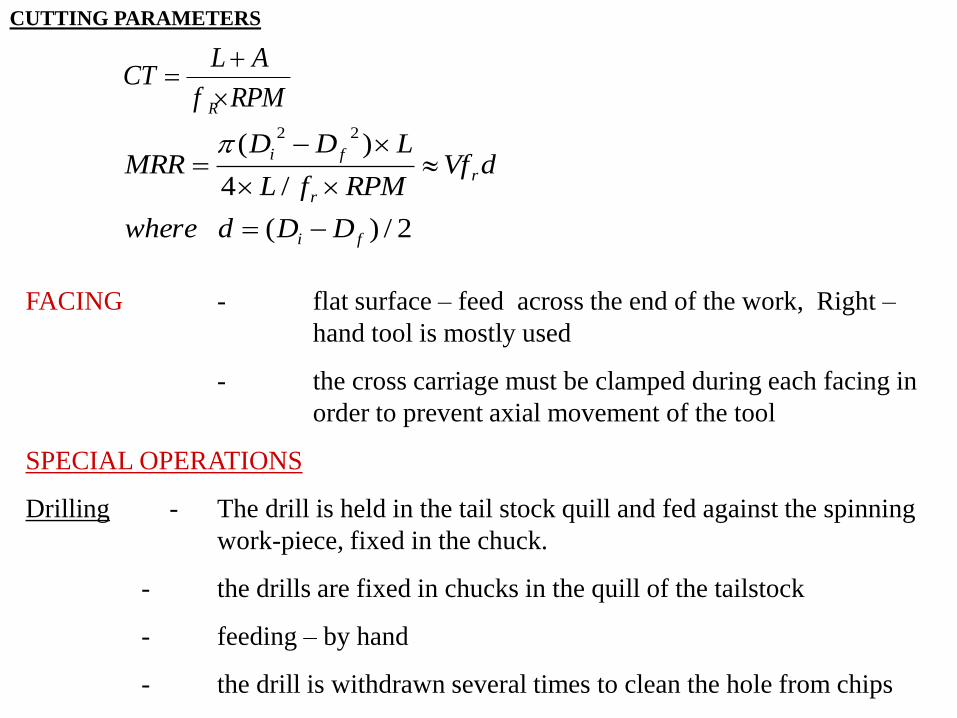
CUTTING PARAMETERS
RPMf
ALCT
R
2/)(
/4
)(22
fi
r
r
fi
DDdwhere
dVfRPMfL
LDDMRR
FACING - flat surface – feed across the end of the work, Right –
hand tool is mostly used
- the cross carriage must be clamped during each facing in
order to prevent axial movement of the tool
SPECIAL OPERATIONS
Drilling - The drill is held in the tail stock quill and fed against the spinning
work-piece, fixed in the chuck.
- the drills are fixed in chucks in the quill of the tailstock
- feeding – by hand
- the drill is withdrawn several times to clean the hole from chips
Reaming - the same mode as for drilling direction of the axis cannot be
changed
Boring - enlarging of an existing hole initiated by boring
- the hole may be redressed, making it to be concentric to the axis of
rotation
- geometric deviation can be solved
- work-piece held in the chuck.
Tools * larger relief angles are used to prevent rubbing of the tool
* less loaded ( smaller feeds)
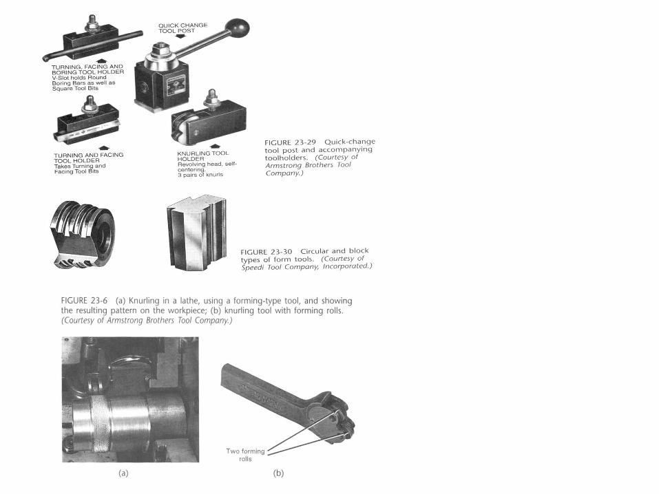
Knurling : chip-less – cold forming process – special tool
EQUIPMENT FOR LATHES (ACCESSORIES)
A. Work-piece supporting equipment
1. Between centers
2. In chuck
3. In collet
4. On a face plate
5. On the carriage, on the tailstock

6. Mandrels-for pieces that have “dish shape”
– to be machined from both directions.
a. solid mandrel 1:2000 taper pressed on mandrel
b. gang or drill mandrels – for cylindrical surface
c. cone mandrels for pieces with different hole sizes
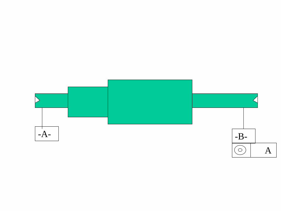
-A- -B-
A
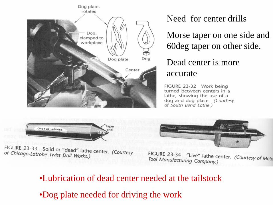
•Lubrication of dead center needed at the tailstock
•Dog plate needed for driving the work
Need for center drills
Morse taper on one side and
60deg taper on other side.
Dead center is more
accurate
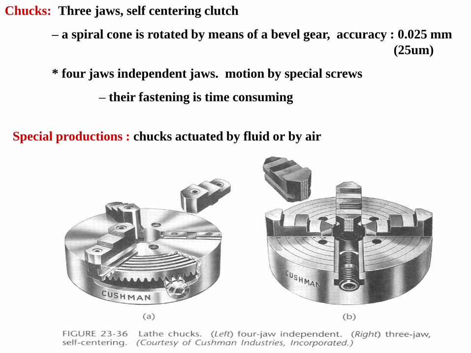
Chucks: Three jaws, self centering clutch
– a spiral cone is rotated by means of a bevel gear, accuracy : 0.025 mm
(25um)
* four jaws independent jaws. motion by special screws
– their fastening is time consuming
Special productions : chucks actuated by fluid or by air
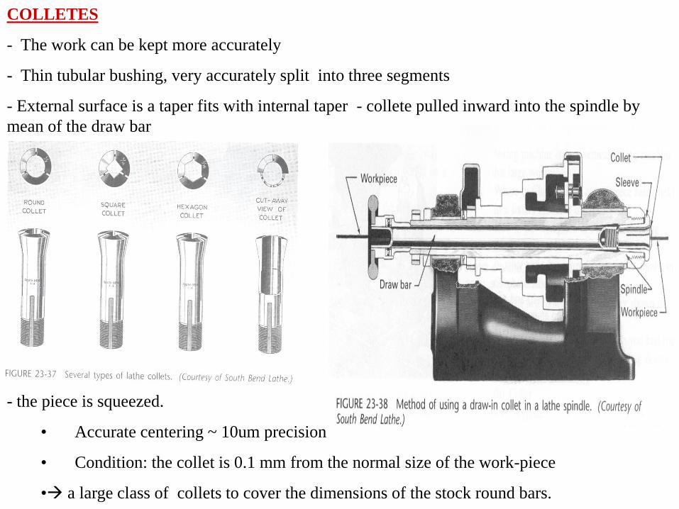
COLLETES
- The work can be kept more accurately
- Thin tubular bushing, very accurately split into three segments
- External surface is a taper fits with internal taper - collete pulled inward into the spindle by
mean of the draw bar
- the piece is squeezed.
• Accurate centering ~ 10um precision
• Condition: the collet is 0.1 mm from the normal size of the work-piece
• a large class of collets to cover the dimensions of the stock round bars.
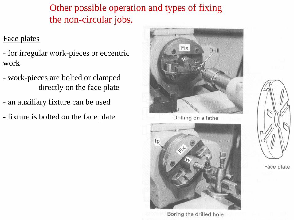
Other possible operation and types of fixing
the non-circular jobs.
Face plates
- for irregular work-pieces or eccentric
work
- work-pieces are bolted or clamped
directly on the face plate
- an auxiliary fixture can be used
- fixture is bolted on the face plate
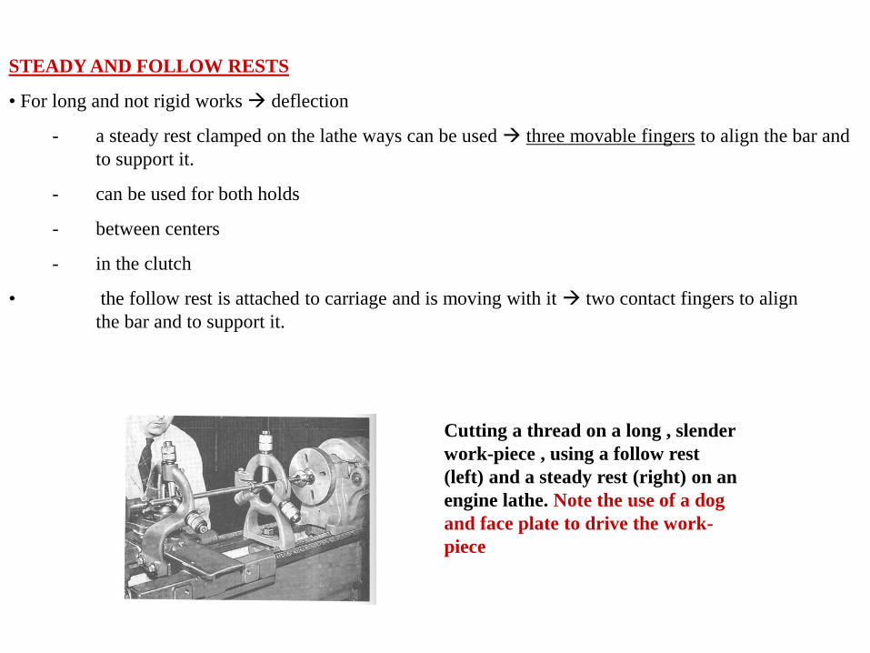
STEADY AND FOLLOW RESTS
• For long and not rigid works deflection
- a steady rest clamped on the lathe ways can be used three movable fingers to align the bar and
to support it.
- can be used for both holds
- between centers
- in the clutch
• the follow rest is attached to carriage and is moving with it two contact fingers to align
the bar and to support it.
Cutting a thread on a long , slender
work-piece , using a follow rest
(left) and a steady rest (right) on an
engine lathe. Note the use of a dog
and face plate to drive the work-
piece
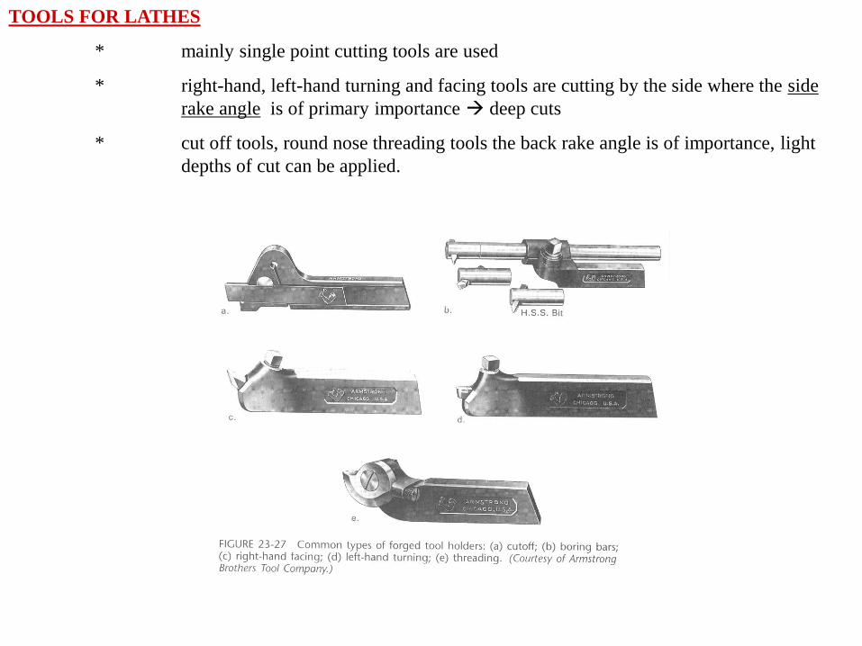
TOOLS FOR LATHES
* mainly single point cutting tools are used
* right-hand, left-hand turning and facing tools are cutting by the side where the side
rake angle is of primary importance deep cuts
* cut off tools, round nose threading tools the back rake angle is of importance, light
depths of cut can be applied.
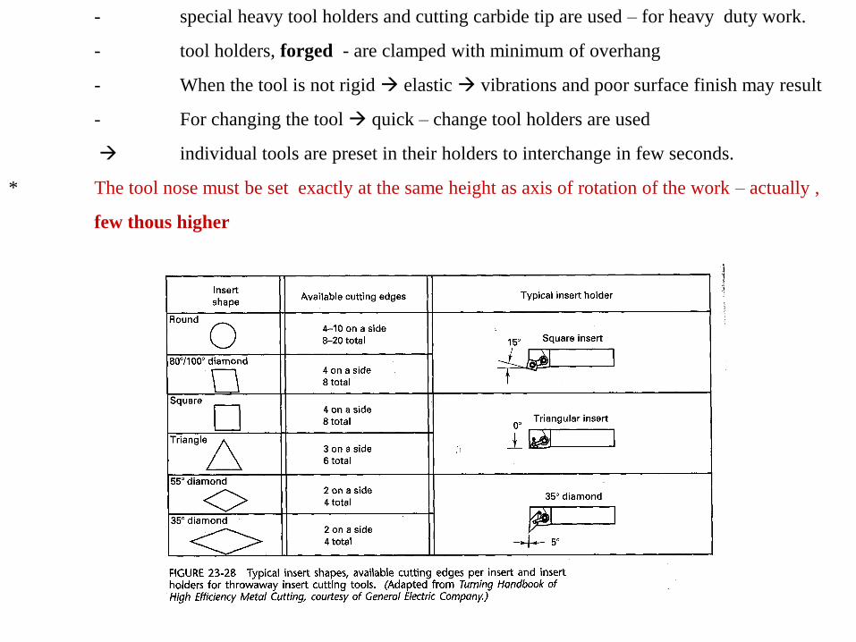
- special heavy tool holders and cutting carbide tip are used – for heavy duty work.
- tool holders, forged - are clamped with minimum of overhang
- When the tool is not rigid elastic vibrations and poor surface finish may result
- For changing the tool quick – change tool holders are used
individual tools are preset in their holders to interchange in few seconds.
* The tool nose must be set exactly at the same height as axis of rotation of the work – actually ,
few thous higher
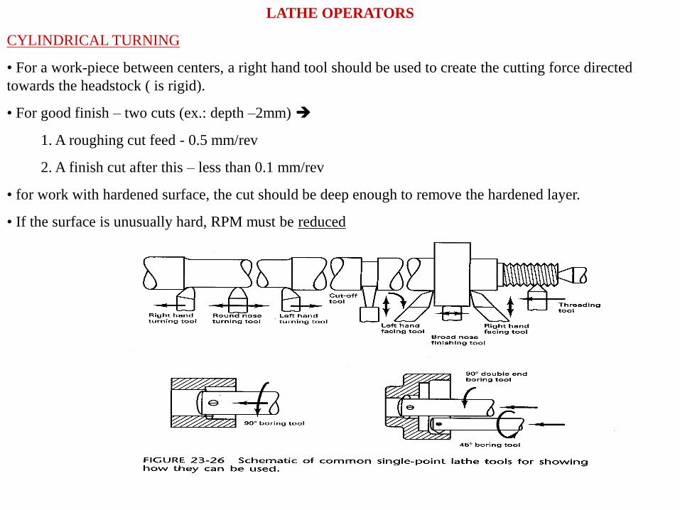
LATHE OPERATORS
CYLINDRICAL TURNING
• For a work-piece between centers, a right hand tool should be used to create the cutting force directed
towards the headstock ( is rigid).
• For good finish – two cuts (ex.: depth –2mm)
1. A roughing cut feed - 0.5 mm/rev
2. A finish cut after this – less than 0.1 mm/rev
• for work with hardened surface, the cut should be deep enough to remove the hardened layer.
• If the surface is unusually hard, RPM must be reduced
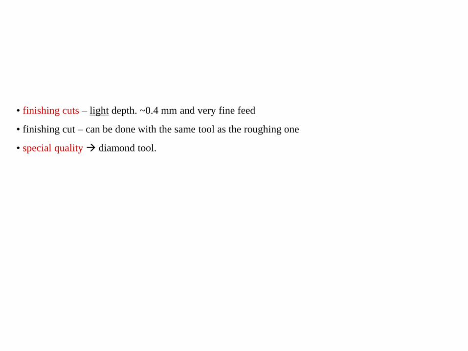
• finishing cuts – light depth. ~0.4 mm and very fine feed
• finishing cut – can be done with the same tool as the roughing one
• special quality diamond tool.
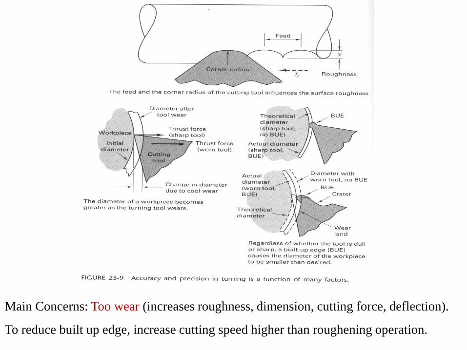
Main Concerns: Too wear (increases roughness, dimension, cutting force, deflection).
To reduce built up edge, increase cutting speed higher than roughening operation.
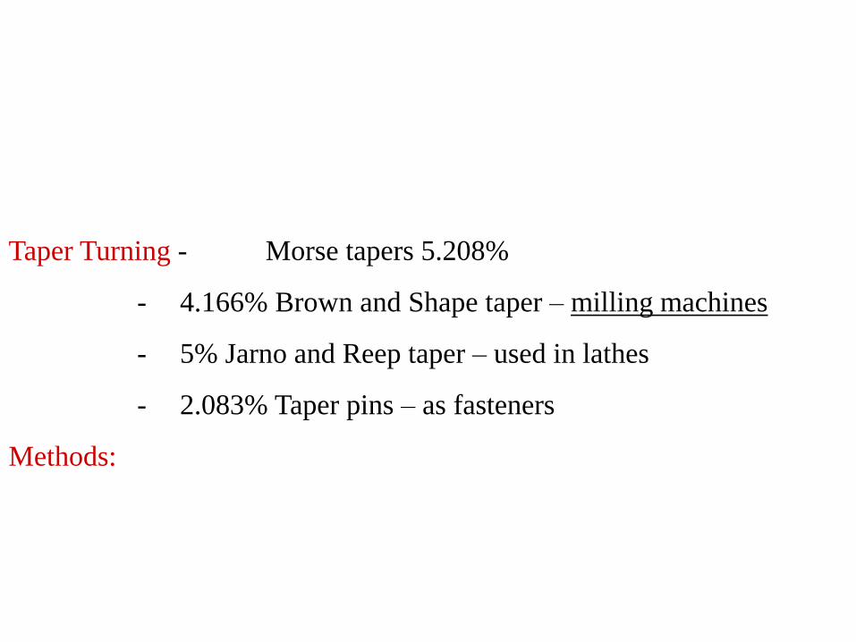
Taper Turning - Morse tapers 5.208%
- 4.166% Brown and Shape taper – milling machines
- 5% Jarno and Reep taper – used in lathes
- 2.083% Taper pins – as fasteners
Methods:
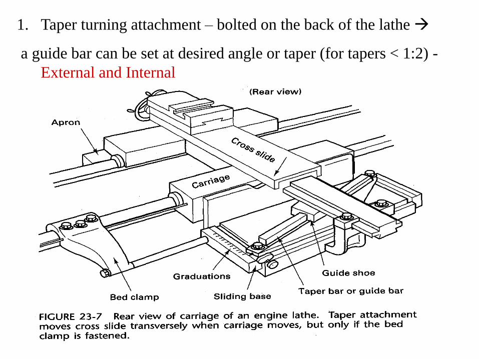
1. Taper turning attachment – bolted on the back of the lathe
a guide bar can be set at desired angle or taper (for tapers < 1:2) -
External and Internal
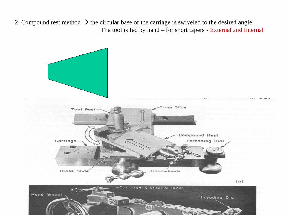
2. Compound rest method the circular base of the carriage is swiveled to the desired angle.
The tool is fed by hand – for short tapers - External and Internal
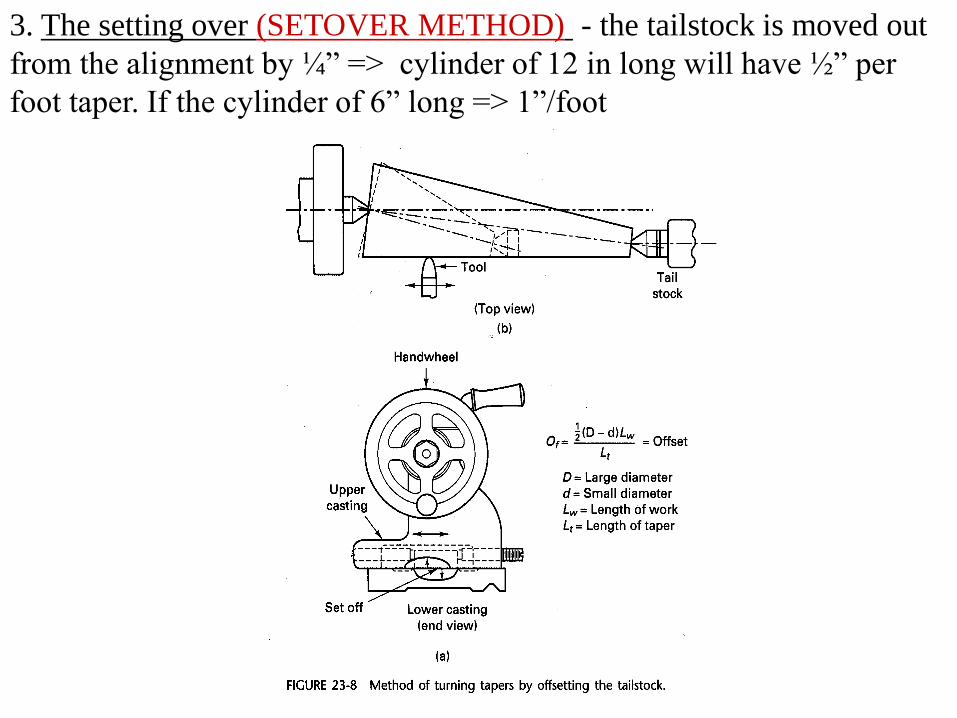
3. The setting over (SETOVER METHOD) - the tailstock is moved out
from the alignment by ¼” => cylinder of 12 in long will have ½” per
foot taper. If the cylinder of 6” long => 1”/foot
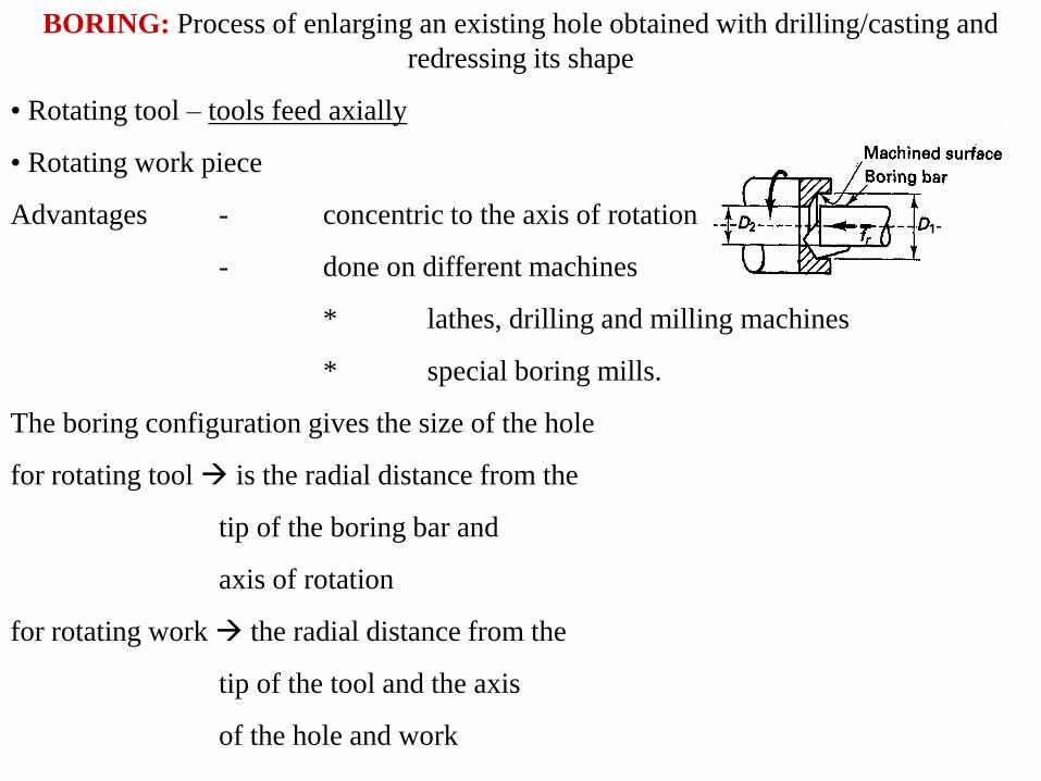
BORING: Process of enlarging an existing hole obtained with drilling/casting and
redressing its shape
• Rotating tool – tools feed axially
• Rotating work piece
Advantages - concentric to the axis of rotation
- done on different machines
* lathes, drilling and milling machines
* special boring mills.
The boring configuration gives the size of the hole
for rotating tool is the radial distance from the
tip of the boring bar and
axis of rotation
for rotating work the radial distance from the
tip of the tool and the axis
of the hole and work
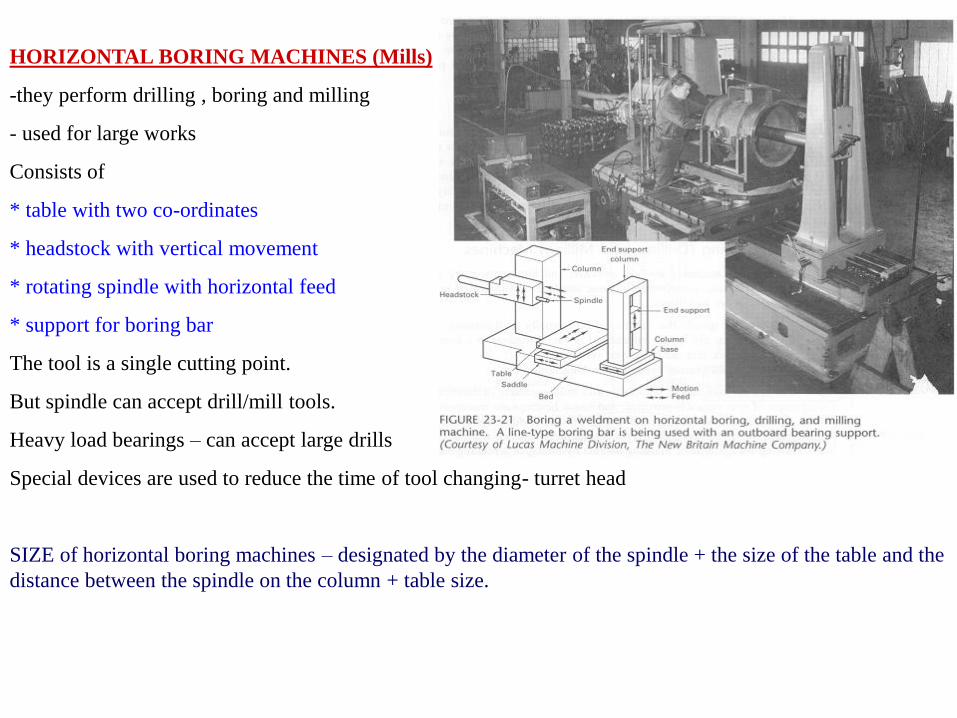
HORIZONTAL BORING MACHINES (Mills)
-they perform drilling , boring and milling
- used for large works
Consists of
* table with two co-ordinates
* headstock with vertical movement
* rotating spindle with horizontal feed
* support for boring bar
The tool is a single cutting point.
But spindle can accept drill/mill tools.
Heavy load bearings – can accept large drills
Special devices are used to reduce the time of tool changing- turret head
SIZE of horizontal boring machines – designated by the diameter of the spindle + the size of the table and the
distance between the spindle on the column + table size.
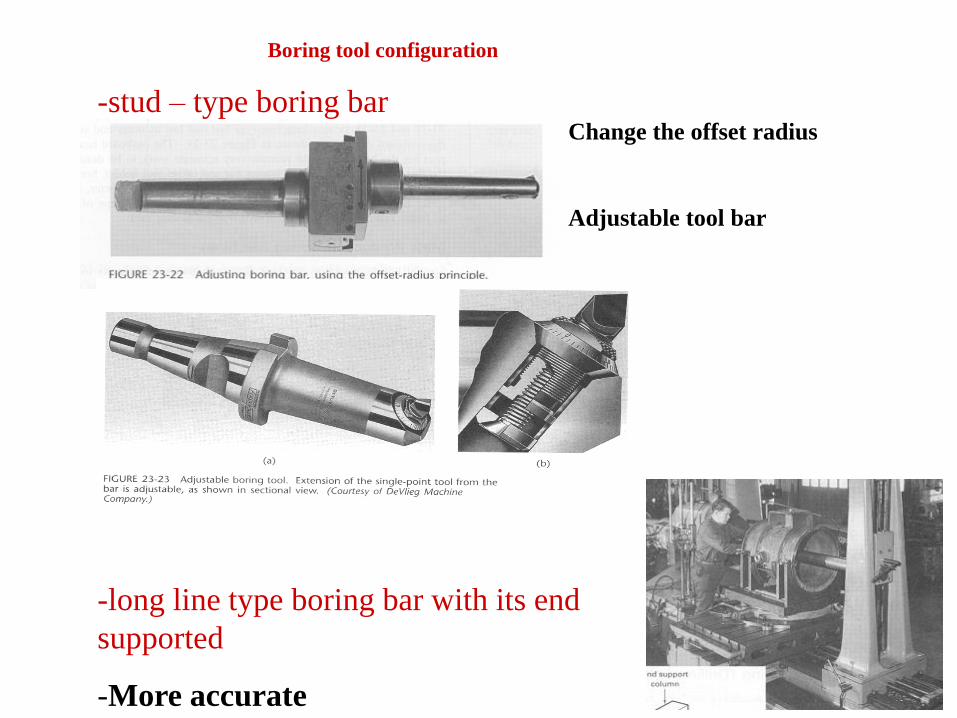
Boring tool configuration
-stud – type boring bar
-long line type boring bar with its end
supported
-More accurate
Change the offset radius
Adjustable tool bar
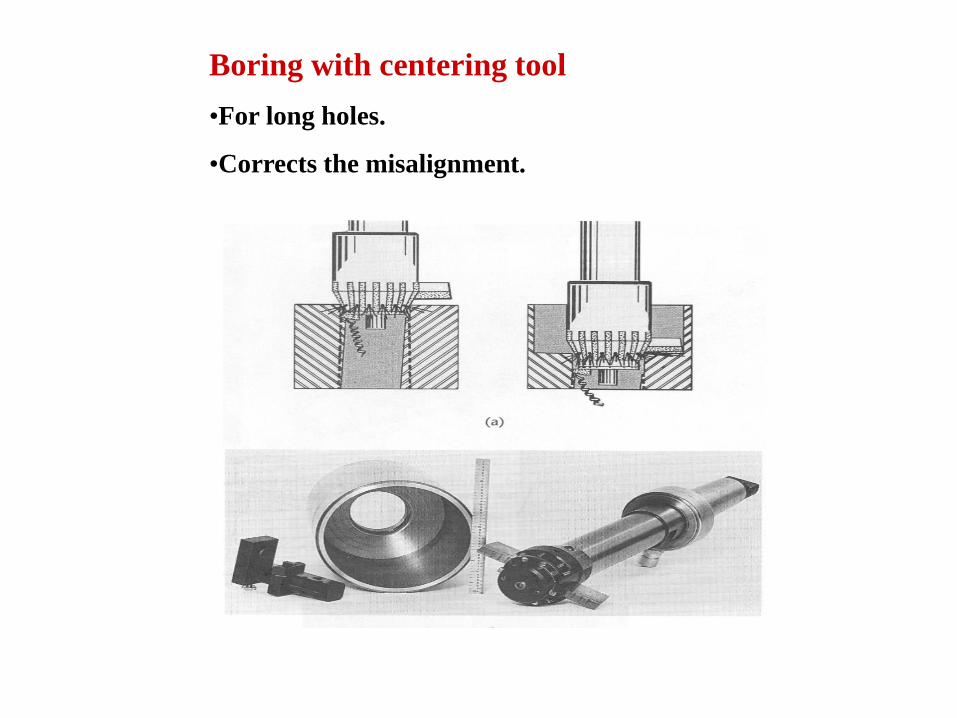
Boring with centering tool
•For long holes.
•Corrects the misalignment.
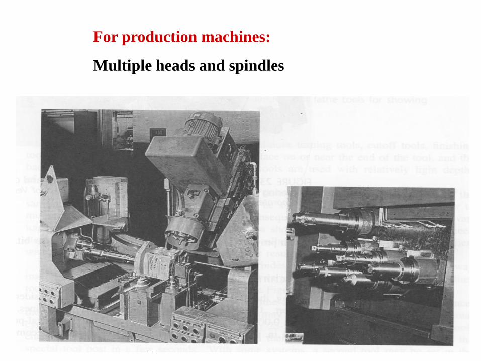
For production machines:
Multiple heads and spindles
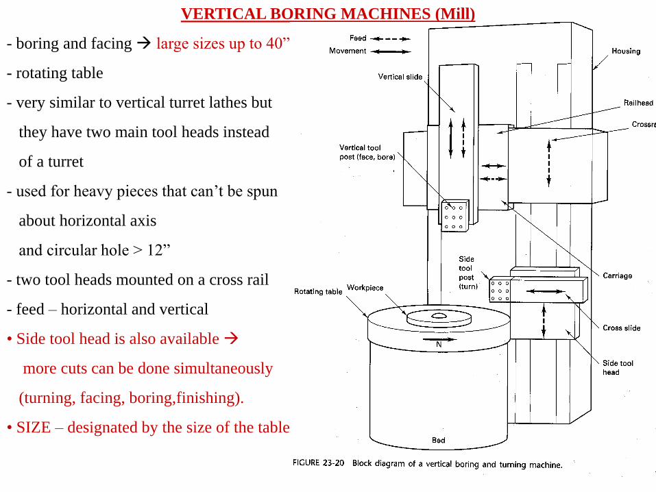
VERTICAL BORING MACHINES (Mill)
- boring and facing large sizes up to 40” dia
- rotating table
- very similar to vertical turret lathes but
they have two main tool heads instead
of a turret
- used for heavy pieces that can’t be spun
about horizontal axis
and circular hole > 12”
- two tool heads mounted on a cross rail
- feed – horizontal and vertical
• Side tool head is also available
more cuts can be done simultaneously
(turning, facing, boring,finishing).
• SIZE – designated by the size of the table.
AUTOMATIC VERTICAL BORING MACHINES
- used to bore the cylinder block of the engine
- bore holes simultaneously.
JIG BORERS - to bore jig and fixtures in the tool room
- are equipped with co-ordinate controlling devices.
-Very precise spindle and bearings.
- operated by numerical controls.
- expensive accurate
Boring operations;
– the same principles in drilling small depth and feeds are sometimes necessary because of the dia.
Boring tools
- multiple cutter boring tool – like milling cutter for cylindrical internal surfaces similar to reaming