tubular gas-fired unit heaters - mesteksa.commesteksa.com/fileuploads/literature/sterling gas...
TRANSCRIPT
82%+ EFFICIENT
HVAC PRODUCTS
TUBULAR GAS-FIRED UNIT HEATERS
GTFC-6
2HVAC PRODUCTS
Model GG
General Information 3 Performance Data 4 Dimensional Figures 5 Model Number Description 6
Model TF
General Information 7 Performance and Dimensional Data 8 Model Number Description 9
Optional Accessories
Factory Installed 10 Field Installed 10
Heat Throw Data
Standard Unit 11 30° Nozzle 11 60° Nozzle 12 90° Nozzle 12 Nozzle Dimensions 13
Warranty 14
Typical Standard Specifi cation
Model GG 15 Model TF 15
Table of Contents

3
The Sterling Model “GG” Low Profi le gas-fi red unit heater is a highly efficient, extremely versatile product. These propeller units combine the latest tubular heat exchanger technology with a unique single-orifice burner system. Units are available in sizes ranging from 30 to 120 MBH in compact, low profi le design.
Residential Garage Certifi edThe Sterling Model “GG” unit heater conforms to the latest ETL certifi cation standards for installations in residential garages. Design certifi cation and our low profi le design makes the Model “GG” unit ideal for residential, commercial and industrial installations.
High Effi ciencyStandard energy saving features like the direct spark ignition and power venting reduces standby losses and offers improved seasonal effi ciencies. “GG” models are certifi ed by ETL as providing over 82%+ thermal (combustion) effi ciency.
Tubular Heat ExchangerThe Sterling tubular heat exchanger has been designed to provide maximum and uniform heat transfer. The low pressure drop associated with this design enables heated air to be evenly distributed to the conditioned space. This curved, non-welded serpentine design experiences low thermal stress making it more durable for significantly longer service life.
Single Orifi ce BurnerSterling Model “GG” units are built with a proprietary, single orifi ce burner system: one burner to service and one orifi ce to change for gas conversion. The stainless steel burner box provides even heat distribution to all heat exchanger tubes.
Direct Spark Ignition SystemSterling Model “GG” units utilize a direct spark pilotless ignition of the burner, providing fast heat delivery. This highly reliable and effi cient ignition system incorporates an integrated electronic control board to regulate the system sequence of operation, including an onboard LED indicator for simple troubleshooting.
Dual VentingSterling Model “GG” units are agency certified for both standard and separated combustion venting. Units are shipped to accommodate either category I or category III horizontal or vertical venting. With the addition of a Sterling concentric vent kit, the unit can be installed as a separated combustion unit.
10-Year WarrantySterling warranties the heat exchanger, f lue collector and burner of the Model “GG” to be free from defects in materials and workmanship for a period of 10 years from the date of manufacture.
Standard Features• Residential Certifi cation
• Single Orifi ce Burner System
• Direct Spark Ignition
• 82%+ Thermal Effi ciency
• 20-GA Steel Cabinet with Baked Enamel Finish.
• 115/1/60 Fan Motor with Internal Overload Protection
• Power Vented
• Redundant Single Stage Gas Valve
• OSHA Fan Guard
• 120/24 Control Transformer
• Right Hand Control Access – Field Convertible to Left Hand
• Field Convertible to Separated Combustion
• Gas Conversion Kit Included
• Easy Access Control Panel
• 321 Stainless Steel Burner Box
• High Limit Switch
• Air Pressure Switch
• 10 Year Heat Exchanger Warranty
Model GG Gas-Fired Unit Heaters
Model GG120 Model GG045
4HVAC PRODUCTS
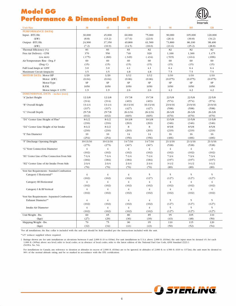
Model GG Performance & Dimensional Data Unit Size 30 45 60 75 90 105 120 PERFORMANCE DATA† Input - BTU/Hr. 30,000 45,000 60,000 75,000 90,000 105,000 120,000
(kW) (8.8) (13.2) (17.6) (22.0) (26.4) (30.8) (34.2)
Output - BTU/Hr. 24,900 37,350 49,800 61,500 73,800 86,100 98,400
(kW) (7.2) (10.9) (14.5) (18.0) (21.6) (25.2) (28.8)
Thermal Effi ciency (%) 83 83 83 82 82 82 82
Free Air Delivery - CFM 370 550 740 920 1,100 1,300 1,475
(cu. m/s) (.175) (.260) (.349) (.434) (.519) (.614) (.696)
Air Temperature Rise - Deg. F 60 60 60 60 60 60 60
(Deg. C) (15) (15) (15) (15) (15) (15) (15)
Full Load Amps at 120V 3.0 3.0 4.1 4.1 6.4 6.4 6.4
Maximum Circuit Ampacity 3.5 3.5 4.8 4.8 7.5 7.5 7.5
MOTOR DATA: Motor HP 1/20 1/20 1/12 1/12 1/10 1/10 1/10
Motor (kW) (0.04) (0.04) (0.06) (0.06) (0.075) (0.075) (0.075)
Motor Type SP SP SP SP SP SP SP
R.P.M. 1650 1650 1050 1050 1050 1050 1050
Motor Amps @ 115V 1.9 1.9 2.6 2.6 4.2 4.2 4.2
DIMENSIONAL DATA - inches (mm) “A” Jacket Height 12-3/8 12-3/8 15-7/8 15-7/8 22-5/8 22-5/8 22-5/8
(314) (314) (403) (403) (574) (574) (574)
“B” Overall Height 13-1/4 13-1/4 16-13/16 16-13/16 23-9/16 23-9/16 23-9/16
(337) (337) (427) (427) (598) (598) (598)
“C” Overall Depth 25-7/8 25-7/8 26-3/16 26-3/16 26-3/8 26-3/8 26-3/8
(632) (632) (665) (665) (670) (670) (670)
“D1” Center Line Height of Flue* 8-1/2 8-1/2 10-3/8 10-3/8 13-5/8 13-5/8 13-5/8
(216) (216) (263) (263) (346) (346) (346)
“D2” Center Line Height of Air Intake 8-1/2 8-1/2 8 8 8-5/8 8-5/8 8-5/8
(216) (216) (203) (203) (219) (219) (219)
“E” Fan Diameter 10 10 14 14 16 16 16
(254) (254) (356) (356) (406) (406) (406)
“F” Discharge Opening Height 10-13/16 10-13/16 14-7/16 14-7/16 21-3/16 21-3/16 21-3/16
(275) (275) (367) (367) (538) (538) (538)
“G” Vent Connection Diameter 4 4 4 4 4 4 4
(102) (102) (102) (102) (102) (102) (102)
“H1” Center Line of Flue Connection From Side 7-1/4 7-1/4 7-1/4 7-1/4 7-3/4 7-3/4 7-3/4
(184) (184) (184) (184) (197) (197) (197)
“H2” Center Line of Air Intake From Side 2-3/4 2-3/4 2-3/4 2-3/4 3-1/2 3-1/2 3-1/2
(70) (70) (70) (70) (89) (89) (89)
Vent Size Requirements - Standard Combustion
Category I Horizontal** 4 4 4 5 5 5 5
(102) (102) (102) (127) (127) (127) (127)
Category III Horizontal 4 4 4 4 4 4 4
(102) (102) (102) (102) (102) (102) (102)
Category I & III Vertical 4 4 4 4 4 4 4
(102) (102) (102) (102) (102) (102) (102)
Vent Size Requirements - Separated Combustion
Exhaust Diameter** 4 4 4 4 5 5 5
(102) (102) (102) (102) (127) (127) (127)
Intake Air Diameter 4 4 4 4 5 5 5
(102) (102) (102) (102) (127) (127) (127)
Unit Weight - lbs. 60 65 80 85 95 105 110
(kgs) (27) (29) (36) (39) (43) (48) (50)
Shipping Weight - lbs. 70 75 90 95 110 115 120
(kgs) (32) (34) (41) (43) (50) (52) (54)
*For all installations, the fl ue collar is included with the unit and should be fi eld installed per the instructions included with the unit.
**4-5" reducer supplied where required.
† Ratings shown are for unit installations at elevations between 0 and 2,000 ft (0 to 610m). For unit installations in U.S.A. above 2,000 ft. (610m), the unit input must be derated 4% for each 1,000 ft. (305m) above sea level; refer to local codes, or in absence of local codes, refer to the latest edition of the National Fuel Gas Code, ANSI Standard Z223.1 (N.F.P.A. No. 54).
For installations in Canada, any reference to deration at altitudes in excess of 2,000 ft. (610m) are to be ignored. At altitudes of 2,000 ft. to 4,500 ft. (610 to 1372m), the unit must be derated to 90% of the normal altitude rating, and be so marked in accordance with the ETL certifi cation.
5
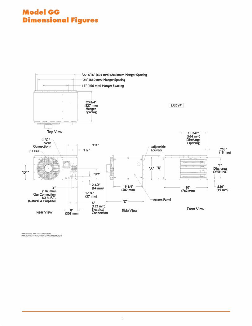
Model GG Dimensional Figures
DIMENSIONS .XXX STANDARD UNITSDIMENSIONS IN PARENTHESIS (XXX) MILLIMETERS
6HVAC PRODUCTS
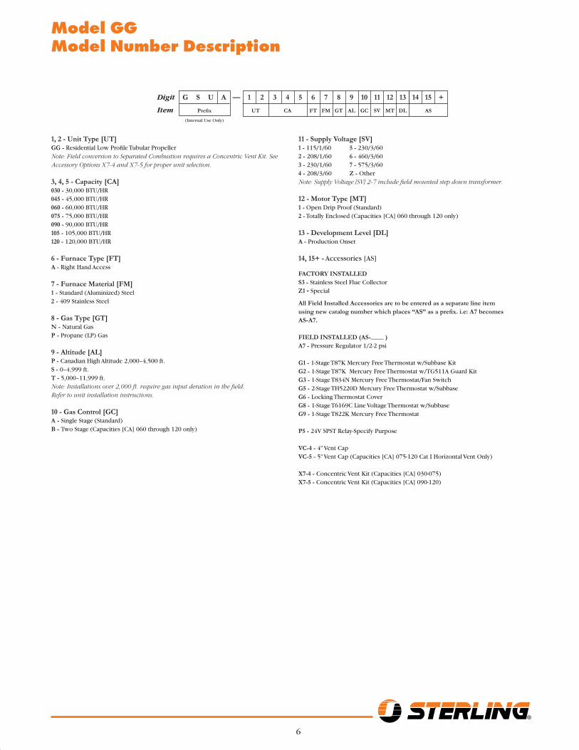
Model GG Model Number Description
11 - Supply Voltage [SV]1 - 115/1/60 5 - 230/3/602 - 208/1/60 6 - 460/3/603 - 230/1/60 7 - 575/3/604 - 208/3/60 Z - OtherNote: Supply Voltage [SV] 2-7 include fi eld mounted step down transformer.
12 - Motor Type [MT]1 - Open Drip Proof (Standard)2 - Totally Enclosed (Capacities [CA] 060 through 120 only)
13 - Development Level [DL]A - Production Onset
14, 15+ - Accessories [AS]
FACTORY INSTALLEDS3 - Stainless Steel Flue CollectorZ1 - Special
All Field Installed Accessories are to be entered as a separate line item using new catalog number which places “AS” as a prefi x. i.e: A7 becomes AS-A7.
FIELD INSTALLED (AS-____ )A7 - Pressure Regulator 1/2-2 psi
G1 - 1-Stage T87K Mercury Free Thermostat w/Subbase KitG2 - 1-Stage T87K Mercury Free Thermostat w/TG511A Guard KitG3 - 1-Stage T834N Mercury Free Thermostat/Fan SwitchG5 - 2-Stage TH5220D Mercury Free Thermostat w/SubbaseG6 - Locking Thermostat CoverG8 - 1-Stage T6169C Line Voltage Thermostat w/SubbaseG9 - 1-Stage T822K Mercury Free Thermostat
P5 - 24V SPST Relay-Specify Purpose
VC-4 - 4" Vent CapVC-5 - 5" Vent Cap (Capacities [CA] 075-120 Cat I Horizontal Vent Only)
X7-4 - Concentric Vent Kit (Capacities [CA] 030-075)X7-5 - Concentric Vent Kit (Capacities [CA] 090-120)
1, 2 - Unit Type [UT]GG - Residential Low Profi le Tubular PropellerNote: Field conversion to Separated Combustion requires a Concentric Vent Kit. See Accessory Options X7-4 and X7-5 for proper unit selection.
3, 4, 5 - Capacity [CA]030 - 30,000 BTU/HR 045 - 45,000 BTU/HR 060 - 60,000 BTU/HR 075 - 75,000 BTU/HR 090 - 90,000 BTU/HR 105 - 105,000 BTU/HR 120 - 120,000 BTU/HR
6 - Furnace Type [FT]A - Right Hand Access
7 - Furnace Material [FM]1 - Standard (Aluminized) Steel2 - 409 Stainless Steel
8 - Gas Type [GT]N - Natural GasP - Propane (LP) Gas
9 - Altitude [AL]P - Canadian High Altitude 2,000–4,500 ft.S - 0–4,999 ft.T - 5,000–11,999 ft.Note: Installations over 2,000 ft. require gas input deration in the fi eld. Refer to unit installation instructions.
10 - Gas Control [GC]A - Single Stage (Standard)B - Two Stage (Capacities [CA] 060 through 120 only)
Digit G S U A — 1 2 3 4 5 6 7 8 9 10 11 12 13 14 15 +
Item Prefi x UT CA FT FM GT AL GC SV MT DL AS
(Internal Use Only)
7
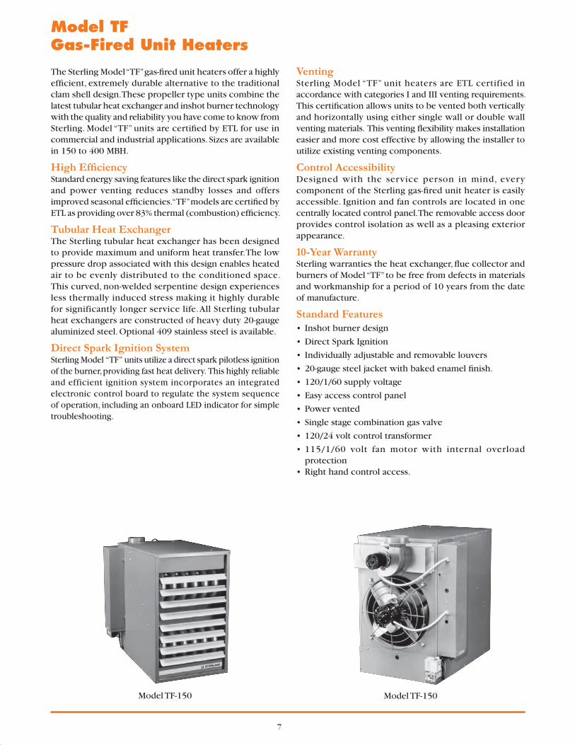
The Sterling Model “TF” gas-fi red unit heaters offer a highly effi cient, extremely durable alternative to the traditional clam shell design. These propeller type units combine the latest tubular heat exchanger and inshot burner technology with the quality and reliability you have come to know from Sterling. Model “TF” units are certifi ed by ETL for use in commercial and industrial applications. Sizes are available in 150 to 400 MBH.
High Effi ciencyStandard energy saving features like the direct spark ignition and power venting reduces standby losses and offers improved seasonal effi ciencies. “TF” models are certifi ed by ETL as providing over 83% thermal (combustion) effi ciency.
Tubular Heat ExchangerThe Sterling tubular heat exchanger has been designed to provide maximum and uniform heat transfer. The low pressure drop associated with this design enables heated air to be evenly distributed to the conditioned space. This curved, non-welded serpentine design experiences less thermally induced stress making it highly durable for significantly longer service life. All Sterling tubular heat exchangers are constructed of heavy duty 20-gauge aluminized steel. Optional 409 stainless steel is available.
Direct Spark Ignition SystemSterling Model “TF” units utilize a direct spark pilotless ignition of the burner, providing fast heat delivery. This highly reliable and efficient ignition system incorporates an integrated electronic control board to regulate the system sequence of operation, including an onboard LED indicator for simple troubleshooting.
VentingSterling Model “TF” unit heaters are ETL certified in accordance with categories I and III venting requirements. This certifi cation allows units to be vented both vertically and horizontally using either single wall or double wall venting materials. This venting fl exibility makes installation easier and more cost effective by allowing the installer to utilize existing venting components.
Control AccessibilityDesigned with the service person in mind, every component of the Sterling gas-fi red unit heater is easily accessible. Ignition and fan controls are located in one centrally located control panel. The removable access door provides control isolation as well as a pleasing exterior appearance.
10-Year WarrantySterling warranties the heat exchanger, fl ue collector and burners of Model “TF” to be free from defects in materials and workmanship for a period of 10 years from the date of manufacture.
Standard Features• Inshot burner design
• Direct Spark Ignition
• Individually adjustable and removable louvers
• 20-gauge steel jacket with baked enamel fi nish.
• 120/1/60 supply voltage
• Easy access control panel
• Power vented
• Single stage combination gas valve
• 120/24 volt control transformer
• 115/1/60 volt fan motor with internal overload protection
• Right hand control access.
Model TF Gas-Fired Unit Heaters
Model TF-150 Model TF-150

8HVAC PRODUCTS
Model TF Unit Size 150 175 200 250 300 350 400 PERFORMANCE DATA† Input - BTU/Hr. 150,000 175,000 200,000 250,000 300,000 350,000 400,000
(kW) (43.9) (51.2) (58.6) (73.2) (87.8) (102.5) (117.1)
Output - BTU/Hr. 124,500 145,250 166,000 207,500 249,000 290,500 332,000
(kW) (36.4) (42.5) (48.6) (60.7) (72.9) (85.1) (97.2)
Thermal Effi ciency (%) 83 83 83 83 83 83 83
Free Air Delivery - CFM 2,400 2,850 3,200 3,450 5,000 5,600 5,800
(cu. m/s) (1.133) (1.346) (1.511) (1.629) (2.361) (2.644) (2.738)
Air Temperature Rise - Deg. F 47 46 47 54 45 47 51
(Deg. C) (26) (26) (26) (30) (24) (26) (28)
Full Load Amps at 120V 5.8 8.0 8.0 8.0 11.3 13.5 13.5
MOTOR DATA: Nominal HP (Qty.) 1/4 1/3 1/3 1/3 (2) 1/4 (2) 1/3 (2) 1/3
Actual kW (.19) (.25) (.25) (.25) (2) (.19) (2) (.25) (2) (.25)
Motor Type PSC PSC PSC PSC PSC PSC PSC
R.P.M. 1,140 1,140 1,140 1,140 1,140 1,140 1,140
Amps @ 115V 4.7 5.8 5.8 5.8 9.4 11.6 11.6
DIMENSIONAL DATA - inches (mm) “A” Overall Height to Top of Flue 33-3/4 33-3/4 33-3/4 33-3/4 34 34 34
(857) (857) (857) (857) (864) (864) (864)
“B” Jacket Width of Unit 20-3/4 32-3/4 32-3/4 32-3/4 50-3/4 50-3/4 50-3/4
(527) (831) (831) (831) (1289) (1289) (1289)
“C” Width to Centerline Flue 13-3/8 19-3/8 19-3/8 19-3/8 28-3/8 28-3/8 28-3/8
(340) (492) (492) (492) (721) (721) (721)
“D” Depth to Rear of Housing 11 11 11 11 12-1/4 12-1/4 12-1/4
(279) (279) (279) (279) (311) (311) (311)
“E” Hanging Distance Width 18-5/8 30-5/8 30-5/8 30-5/8 48-5/8 48-5/8 48-5/8
(473) (778) (778) (778) (1235) (1235) (1235)
“F” Discharge Opening Width 18-3/4 30-3/4 30-3/4 30-3/4 48-3/4 48-3/4 48-3/4
(476) (781) (781) (781) (1238) (1238) (1238)
“G” Depth to Centerline Flue 4-3/4 4-3/4 4-3/4 4-3/4 5-1/8 5-1/8 5-1/8
(121) (121) (121) (121) (130) (130) (130)
“H” Discharge Opening Height 24-1/2 24-1/2 24-1/2 24-1/2 24-1/2 24-1/2 24-1/2
(622) (622) (622) (622) (622) (622) (622)
“L” Overall Unit Width 25-1/4 37-1/4 37-1/4 37-1/4 55-1/4 55-1/4 55-1/4
(641) (946) (946) (946) (1403) (1403) (1403)
*Flue Size Diameter - in. 5 5 5 5 6 6 6
(Dia.-mm) (127) (127) (127) (127) (152) (152) (152)
Fan Diameter - in. (Qty.) 16 18 18 18 (2) 16 (2) 18 (2) 18
Gas Inlet-Natural Gas (in.) 1/2 1/2 1/2 3/4 3/4 3/4 3/4
Gas Inlet- LP Gas (in.) 1/2 1/2 1/2 1/2 OR 3/4 1/2 OR 3/4 1/2 OR 3/4 1/2 OR 3/4
Approximate Unit Weight - lbs. 155 191 201 211 307 321 335
(kg) (70) (87) (91) (96) (139) (145) (152)
Approximate Ship Weight - lbs. 195 241 251 261 367 381 395
(kg) (88) (109) (114) (118) (166) (173) (179)
Model TFPerformance & Dimensional Data
DIMENSIONS .XXX STANDARD UNITSDIMENSIONS IN PARENTHESIS (XXX) MILLIMETERS
D4617
† Published ratings are shown for elevations up to 2,000 feet (610m) above sea level. For higher elevations derate 4% for each 1,000 feet (305m) above sea level. In Canada, derate 10% for altitudes 2,000 to 4,500 feet (610 to 1372m).
* Flue collar is factory supplied with unit; to be fi eld installed per included instructions.
C
E(Hanging)
1-3/8"(35)
(Hanging)G
D 32-1/2"(826)11-5/8"
(295)(Hanging)
H(DischargeOpening)
33"
A
B
L
F(Discharge Opening)
1" (25)Electrical Control Panel
Gas Valve
D4617
Rear View Side View Front View
Flue *
9
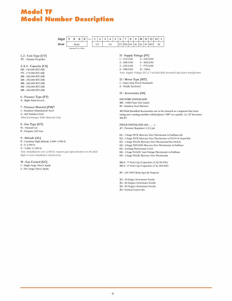
Model TFModel Number Description
11 - Supply Voltage [SV]1 - 115/1/60 5 - 230/3/602 - 208/1/60 6 - 460/3/603 - 230/1/60 7 - 575/3/604 - 208/3/60 Z - OtherNote: Supply Voltage [SV] 2-7 include fi eld mounted step down transformer.
12 - Motor Type [MT]1 - Open Drip Proof (Standard)2 - Totally Enclosed
13 - Accessories [AS]
FACTORY INSTALLEDM6 - OSHA Type Fan Guard S5 - Stainless Steel Burners
All Field Installed Accessories are to be entered as a separate line item using new catalog number which places “AS” as a prefi x. i.e: A7 becomes AS-A7.
FIELD INSTALLED (AS-____ )A7 - Pressure Regulator 1/2-2 psi
G1 - 1-Stage T87K Mercury Free Thermostat w/Subbase KitG2 - 1-Stage T87K Mercury Free Thermostat w/TG511A Guard KitG3 - 1-Stage T834N Mercury Free Thermostat/Fan SwitchG5 - 2-Stage TH5220D Mercury Free Thermostat w/SubbaseG6 - Locking Thermostat CoverG8 - 1-Stage T6169C Line Voltage Thermostat w/SubbaseG9 - 1-Stage T822K Mercury Free Thermostat
M2-2 - 5" Vent Cap (Capacities [CA]150-250)M2-3 - 6" Vent Cap (Capacities [CA] 300-400)
P5 - 24V SPST Relay-Specify Purpose
X2 - 30 Degee Downturn Nozzle X3 - 60 Degree Downturn NozzleX4 - 90 Degree Downturn Nozzle X5 - Vertical Louver Kit
1, 2 - Unit Type [UT]TF - Tubular Propeller
3, 4, 5 - Capacity [CA]150 - 150,000 BTU/HR 175 - 175,000 BTU/HR 200 - 200,000 BTU/HR 250 - 250,000 BTU/HR 300 - 300,000 BTU/HR 350 - 350,000 BTU/HR 400 - 400,000 BTU/HR
6 - Furnace Type [FT]A - Right Hand Access
7 - Furnace Material [FM]*1 - Standard (Aluminized) Steel2 - 409 Stainless Steel *Heat Exchanger Tube Material Only
8 - Gas Type [GT]N - Natural GasP - Propane (LP) Gas
9 - Altitude [AL]P - Canadian High Altitude 2,000–4,500 ft.S - 0–4,999 ft.T - 5,000–11,999 ft.Note: Installations over 2,000 ft. require gas input deration in the fi eld. Refer to unit installation instructions.
10 - Gas Control [GC]1 - Single Stage Direct Spark2 - Two Stage Direct Spark
Digit T X X X — 1 2 3 4 5 6 7 8 9 10 11 12 13 +
Item Prefi x UT CA FT FM GT AL GC SV MT AS
(Internal Use Only)
10HVAC PRODUCTS
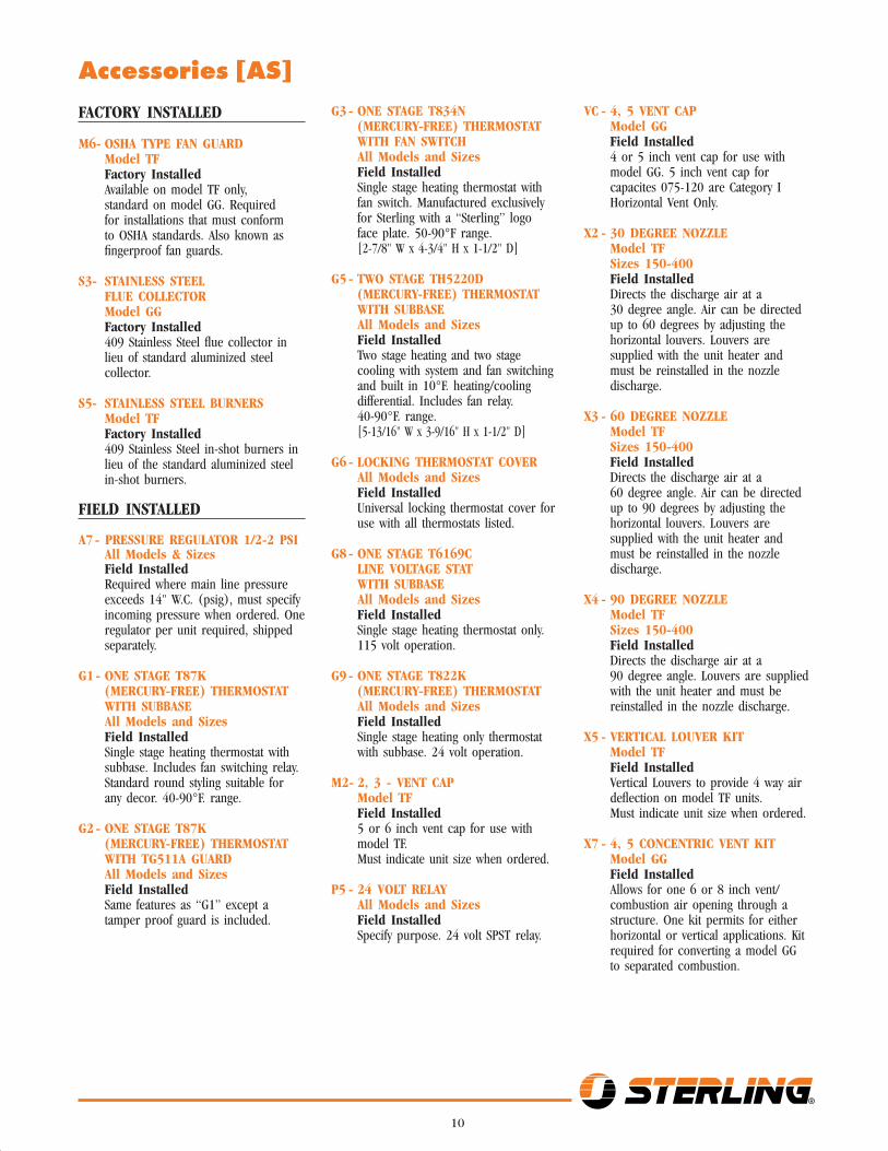
FACTORY INSTALLED
M6 - OSHA TYPE FAN GUARD Model TF Factory Installed Available on model TF only,
standard on model GG. Required for installations that must conform to OSHA standards. Also known as fi ngerproof fan guards.
S3 - STAINLESS STEEL FLUE COLLECTOR
Model GG Factory Installed 409 Stainless Steel fl ue collector in
lieu of standard aluminized steel collector.
S5 - STAINLESS STEEL BURNERS Model TF Factory Installed 409 Stainless Steel in-shot burners in
lieu of the standard aluminized steel in-shot burners.
FIELD INSTALLED
A7 - PRESSURE REGULATOR 1/2-2 PSI All Models & Sizes Field Installed
Required where main line pressure exceeds 14" W.C. (psig), must specify incoming pressure when ordered. One regulator per unit required, shipped separately.
G1 - ONE STAGE T87K (MERCURY-FREE) THERMOSTAT WITH SUBBASE All Models and Sizes Field Installed Single stage heating thermostat with
subbase. Includes fan switching relay. Standard round styling suitable for any decor. 40-90°F. range.
G2 - ONE STAGE T87K (MERCURY-FREE) THERMOSTAT WITH TG511A GUARD
All Models and Sizes Field Installed Same features as “G1” except a
tamper proof guard is included.
G3 - ONE STAGE T834N (MERCURY-FREE) THERMOSTAT WITH FAN SWITCH All Models and Sizes Field Installed Single stage heating thermostat with
fan switch. Manufactured exclusively for Sterling with a “Sterling” logo face plate. 50-90°F range.
[2-7/8" W x 4-3/4" H x 1-1/2" D]
G5 - TWO STAGE TH5220D (MERCURY-FREE) THERMOSTAT WITH SUBBASE All Models and Sizes Field Installed Two stage heating and two stage
cooling with system and fan switching and built in 10°F. heating/cooling differential. Includes fan relay. 40-90°F. range. [5-13/16" W x 3-9/16" H x 1-1/2" D]
G6 - LOCKING THERMOSTAT COVER All Models and Sizes
Field Installed Universal locking thermostat cover for
use with all thermostats listed.
G8 - ONE STAGE T6169C LINE VOLTAGE STAT WITH SUBBASEAll Models and Sizes
Field Installed Single stage heating thermostat only.
115 volt operation.
G9 - ONE STAGE T822K (MERCURY-FREE) THERMOSTAT All Models and Sizes Field Installed Single stage heating only thermostat
with subbase. 24 volt operation.
M2 - 2, 3 - VENT CAP Model TF Field Installed 5 or 6 inch vent cap for use with
model TF. Must indicate unit size when ordered.
P5 - 24 VOLT RELAY All Models and Sizes Field Installed Specify purpose. 24 volt SPST relay.
Accessories [AS]VC - 4, 5 VENT CAP Model GG Field Installed 4 or 5 inch vent cap for use with
model GG. 5 inch vent cap for capacites 075-120 are Category I Horizontal Vent Only.
X2 - 30 DEGREE NOZZLE Model TF Sizes 150-400 Field Installed Directs the discharge air at a
30 degree angle. Air can be directed up to 60 degrees by adjusting the horizontal louvers. Louvers are supplied with the unit heater and must be reinstalled in the nozzle discharge.
X3 - 60 DEGREE NOZZLE Model TF Sizes 150-400 Field Installed Directs the discharge air at a
60 degree angle. Air can be directed up to 90 degrees by adjusting the horizontal louvers. Louvers are supplied with the unit heater and must be reinstalled in the nozzle discharge.
X4 - 90 DEGREE NOZZLE Model TF Sizes 150-400 Field Installed Directs the discharge air at a
90 degree angle. Louvers are supplied with the unit heater and must be reinstalled in the nozzle discharge.
X5 - VERTICAL LOUVER KIT Model TF Field Installed Vertical Louvers to provide 4 way air
defl ection on model TF units.Must indicate unit size when ordered.
X7 - 4, 5 CONCENTRIC VENT KIT Model GG Field Installed Allows for one 6 or 8 inch vent/
combustion air opening through a structure. One kit permits for either horizontal or vertical applications. Kit required for converting a model GG to separated combustion.
11
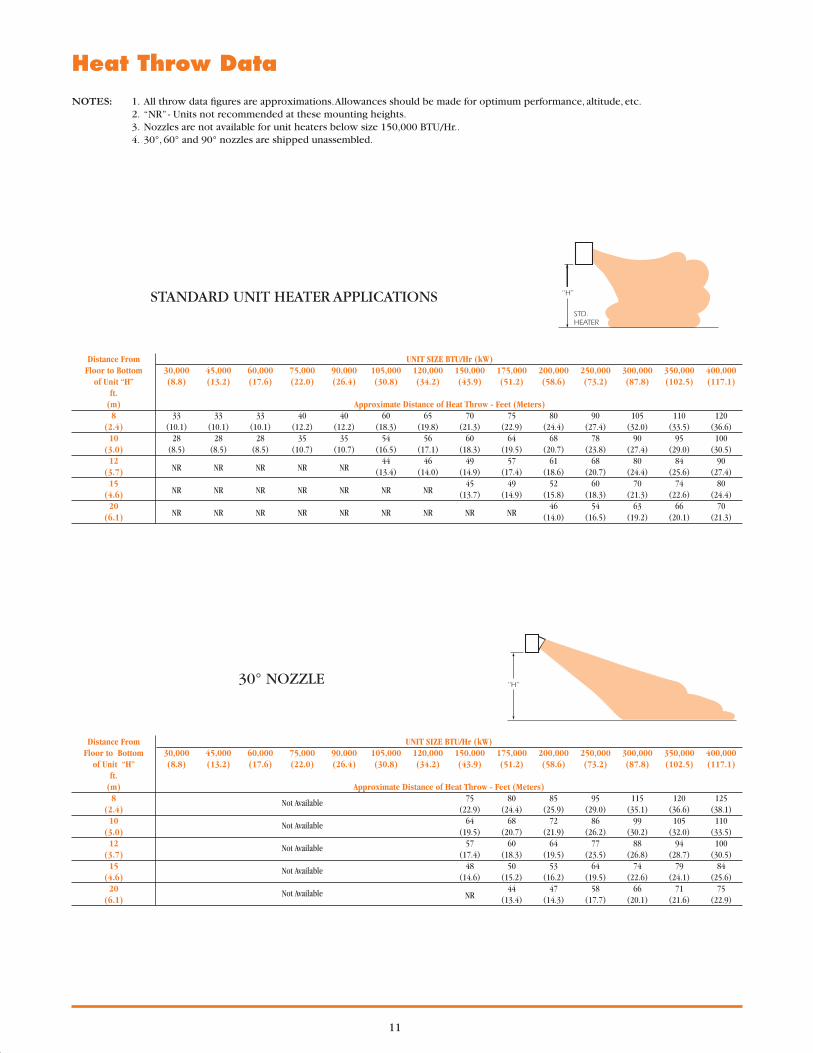
Distance From UNIT SIZE BTU/Hr (kW) Floor to Bottom 30,000 45,000 60,000 75,000 90,000 105,000 120,000 150,000 175,000 200,000 250,000 300,000 350,000 400,000 of Unit “H” (8.8) (13.2) (17.6) (22.0) (26.4) (30.8) (34.2) (43.9) (51.2) (58.6) (73.2) (87.8) (102.5) (117.1) ft. (m) Approximate Distance of Heat Throw - Feet (Meters) 8 33 33 33 40 40 60 65 70 75 80 90 105 110 120 (2.4) (10.1) (10.1) (10.1) (12.2) (12.2) (18.3) (19.8) (21.3) (22.9) (24.4) (27.4) (32.0) (33.5) (36.6) 10 28 28 28 35 35 54 56 60 64 68 78 90 95 100 (3.0) (8.5) (8.5) (8.5) (10.7) (10.7) (16.5) (17.1) (18.3) (19.5) (20.7) (23.8) (27.4) (29.0) (30.5) 12
NR NR NR NR NR 44 46 49 57 61 68 80 84 90
(3.7) (13.4) (14.0) (14.9) (17.4) (18.6) (20.7) (24.4) (25.6) (27.4) 15
NR NR NR NR NR NR NR 45 49 52 60 70 74 80
(4.6) (13.7) (14.9) (15.8) (18.3) (21.3) (22.6) (24.4) 20
NR NR NR NR NR NR NR NR NR 46 54 63 66 70
(6.1) (14.0) (16.5) (19.2) (20.1) (21.3)
STANDARD UNIT HEATER APPLICATIONSApproximate Distance of Heat Throw (Feet)
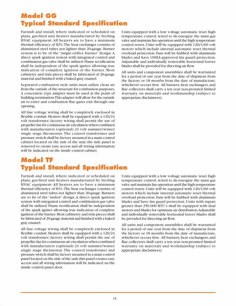
Distance From UNIT SIZE BTU/Hr (kW) Floor to Bottom 30,000 45,000 60,000 75,000 90,000 105,000 120,000 150,000 175,000 200,000 250,000 300,000 350,000 400,000 of Unit “H” (8.8) (13.2) (17.6) (22.0) (26.4) (30.8) (34.2) (43.9) (51.2) (58.6) (73.2) (87.8) (102.5) (117.1) ft. (m) Approximate Distance of Heat Throw - Feet (Meters) 8 75 80 85 95 115 120 125 (2.4)
Not Available (22.9) (24.4) (25.9) (29.0) (35.1) (36.6) (38.1)
10 64 68 72 86 99 105 110 (3.0)
Not Available (19.5) (20.7) (21.9) (26.2) (30.2) (32.0) (33.5)
12 57 60 64 77 88 94 100 (3.7)
Not Available (17.4) (18.3) (19.5) (23.5) (26.8) (28.7) (30.5)
15 48 50 53 64 74 79 84 (4.6)
Not Available (14.6) (15.2) (16.2) (19.5) (22.6) (24.1) (25.6)
20 NR
44 47 58 66 71 75 (6.1)
Not Available (13.4) (14.3) (17.7) (20.1) (21.6) (22.9)
30° NOZZLE
Heat Throw Data
NOTES: 1. All throw data fi gures are approximations. Allowances should be made for optimum performance, altitude, etc. 2. “NR” - Units not recommended at these mounting heights. 3. Nozzles are not available for unit heaters below size 150,000 BTU/Hr.. 4. 30°, 60° and 90° nozzles are shipped unassembled.

12HVAC PRODUCTS
Heat Throw Data
Distance From UNIT SIZE BTU/Hr (kW) Floor to Bottom 30,000 45,000 60,000 75,000 90,000 105,000 125,000 150,000 175,000 200,000 250,000 300,000 350,000 400,000 of Unit “H” (8.8) (13.2) (17.6) (22.0) (26.4) (30.8) (36.6) (43.9) (51.2) (58.6) (73.2) (87.8) (102.5) (117.1) ft. (m) Approximate Distance of Heat Throw - Feet (Meters) 8 85 90 95 110 125 130 138 (2.4)
Not Available (25.9) (27.4) (29.0) (33.5) (38.1) (39.6) (42.1)
10 75 79 83 95 109 115 120 (3.0)
Not Available (22.9) (24.1) (25.3) (29.0) (33.2) (35.1) (36.6)
12 68 72 76 84 100 103 108 (3.7)
Not Available (20.7) (21.9) (23.2) (25.6) (30.5) (31.4) (32.9)
15 56 61 65 71 85 88 94 (4.6)
Not Available (17.1) (18.6) (19.8) (21.6) (25.9) (26.8) (28.7)
20 52 55 59 65 77 81 85 (6.1)
Not Available (15.8) (16.8) (18.0) (19.8) (23.5) (24.7) (25.9)
60° NOZZLE
Distance From UNIT SIZE BTU/Hr (kW) Floor to Bottom 150,000 175,000 200,000 250,000 300,000 350,000 400,000 of Unit “H” (43.9) (51.2) (58.6) (73.2) (87.8) (102.5) (117.1) ft. (m) Approximate Distance of Heat Throw - Feet (Meters) 10
NR NR NR NR NR NR NR
(3.0) 15 40 x 35 45 x 40 50 x 40 60 x 45 70 x 45 80 x 50 100 x 50 (4.6) (12.2) (10.7) (13.7) (12.2) (15.2) (12.2) (18.3) (13.7) (21.3) (13.7) (24.4) (15.2) (30.5) (15.2) 20
NR NR 40 x 35 56 x 40 65 x 40 70 x 45 80 x 45
(6.1) (12.2) (10.7) (17.1) (12.2) (19.8) (12.2) (21.3) (13.7) (24.4) (13.7) 25
NR NR NR 50 x 335 60 x 35 65 x 40 75 x 40
(7.6) (15.2) (10.7) (18.3) (10.7) (19.8) (12.2) (22.9) (12.2) 30
NR NR NR NR 55 x 35 60 x 35 65 x 40
(9.1) (16.8) (10.7) (18.3) (10.7) (19.8) (12.2)
90° NOZZLE

13
SYMBOL NOZZLE TYPE 150 175, 200, 250 300, 350, 400 30 DEG. 20-3/4 32-3/4 50-3/4 WIDTH (527) (832) (1289) A 60 DEG. 20-3/4 32-3/4 50-3/4 in. (527) (832) (1289) (mm) 90 DEG. 20-3/4 32-3/4 50-3/4 (527) (832) (1289) 30 DEG. 31-1/2 31-1/2 31-1/2 HEIGHT (800) (800) (800) B 60 DEG. 31-1/2 31-1/2 31-1/2 in. (800) (800) (800) (mm) 90 DEG. 31-1/2 31-1/2 31-1/2 (800) (800) (800) FURTHEST 30 DEG. 15 15 15 DEPTH (381) (381) (381) C 60 DEG. 25-1/2 25-1/2 25-1/2 in. (648) (648) (648) (mm) 90 DEG. 28-1/4 28-1/4 28-1/4 (718) (718) (718)
*30°, 60° and 90° Nozzles are fi eld assembled.
90° NOZZLE*
NOZZLE DIMENSIONAL DATA CHART
30° NOZZLE* 60° NOZZLE*
A
B
c
A
B
c
B33
Nozzle Dimensions(Model “TF” only)

14HVAC PRODUCTS
Models GG & TFWarranty
LIMITED WARRANTYSterling Gas-Fired Unit Heaters –
Model “GG” and “TF”
1. STERLING GAS-FIRED TUBULAR UNIT HEATER - MODEL “GG” and “TF” Sterling (“the Manufacturer”) warrants to the original owner at original installation site that the above models of
Sterling Gas–Fired Heaters (“the Product”) will be free from defects in material or workmanship for one (1) year from the date of shipment from the factory, or one and one–half (1-1/2) years from the date of manufacture, whichever occurs fi rst. Sterling further warrants that the complete heat exchanger, draft hood assembly, and burners will be free from defects in material or workmanship for a period of ten (10) years from the date of manufacture. If upon examination by the Manufacturer the Product is shown to have a defect in material or workmanship during the warranty period, the Manufacturer will repair or replace, at its option, that part of the Product which is shown to be defective.
2. This limited warranty does not apply: (a) if the Product has been subjected to misuse or neglect, has been accidentally or intentionally damaged, has
not been installed, maintained or operated in accordance with the furnished written instructions, or has been altered or modifi ed in any way by any unauthorized person.
(b) to any expenses, including labor or material, incurred during removal or reinstallation of the Product. (c) to any damage due to corrosion by chemicals, including halogenated hydrocarbons, precipitated in the air. (d) to any workmanship of the installer of the Product.3. This limited warranty is conditional upon: (a) advising the installing contractor, who will in turn notify the distributor or manufacturer. (b) shipment to the Manufacturer of that part of the Product thought to be defective. Goods can only be returned
with prior written approval of the Manufacturer. All returns must be freight prepaid. (c) determination in the reasonable opinion of the Manufacturer that there exists a defect in material or
workmanship.4. Repair or replacement of any part under this Limited Warranty shall not extend the duration of the warranty with
respect to such repaired or replaced part beyond the stated warranty period.5. THIS LIMITED WARRANTY IS IN LIEU OF ALL OTHER WARRANTIES, EITHER EXPRESS OR IMPLIED, AND
ALL SUCH OTHER WARRANTIES, INCLUDING WITHOUT LIMITATION IMPLIED WARRANTIES OF MERCHANTABILITY OR FITNESS FOR A PARTICULAR PURPOSE, ARE HEREBY DISCLAIMED AND EXCLUDED FROM THIS LIMITED WARRANTY. IN NO EVENT SHALL THE MANUFACTURER BE LIABLE IN ANY WAY FOR ANY CONSEQUENTIAL, SPECIAL, OR INCIDENTAL DAMAGES OF ANY NATURE WHATSOEVER, OR FOR ANY AMOUNTS IN EXCESS OF THE SELLING PRICE OF THE PRODUCT OR ANY PARTS THEREOF FOUND TO BE DEFECTIVE. THIS LIMITED WARRANTY GIVES THE ORIGINAL OWNER OF THE PRODUCT SPECIFIC LEGAL RIGHTS. YOU MAY ALSO HAVE OTHER RIGHTS WHICH MAY VARY BY EACH JURISDICTION.
15
Model GGTypical Standard Specifi cationFurnish and install, where indicated or scheduled on plans, gas-fired unit heaters manufactured by Sterling HVAC equipment. All heaters are to have a minimum thermal effi ciency of 82%. The heat exchanger consists of aluminized steel tubes not lighter than 20-gauge. Burner system is to be of the “single-orifice burner” design. A direct spark ignition system with integrated control and combination gas valve shall be utilized. Flame rectifi cation shall be independent of the spark igniter allowing true indication of complete ignition of the burner. Most cabinetry and trim pieces shall be fabricated of 20-gauge material and fi nished with a baked gray enamel.
Separated combustion style units must utilize clean air from the outside of the structure for combustion purposes. A concentric type adapter must be used at the point of building termination. This adapter will allow for the outside air to enter and combustion fl ue gases exit through one opening.
All line voltage wiring shall be completely enclosed in fl exible conduit. Heaters shall be equipped with a 120/24 volt transformer; factory wiring shall permit the use of propeller fan for continuous air circulation when combined with manufacturers (optional) 24 volt summer/winter single stage thermostat. The control transformer and pressure switch shall be factory mounted in a main control cabinet located on the side of the unit; the side panel is removed to create easy access and all wiring information will be indicated on the inside control cabinet.
Units equipped with a low voltage automatic reset high temperature control, wired to de-energize the main gas valve and maintain fan operation until the high temperature control resets. Units will be equipped with 120/1/60 volt motors which include internal automatic reset thermal overload protection. Fans will be hubbed with aluminum blades and have OSHA-approved fan guard protection. Adjustable and individually removable horizontal louver blades shall be provided for directing air fl ow.
All units and component assemblies shall be warranted for a period of one year from the date of shipment from the factory or 18 months from the date of manufacture, whichever occurs fi rst. All burners, heat exchangers, and fl ue collectors shall carry a ten year non-prorated limited warranty on materials and workmanship (subject to appropriate disclaimers).
Model TFTypical Standard Specifi cationFurnish and install, where indicated or scheduled on plans, gas-fired unit heaters manufactured by Sterling HVAC equipment. All heaters are to have a minimum thermal effi ciency of 83%. The heat exchanger consists of aluminized steel tubes not lighter than 20-gauge. Burners are to be of the “inshot” design. A direct spark ignition system with integrated control and combination gas valve shall be utilized. Flame rectifi cation shall be independent of the spark igniter allowing true indication of complete ignition of the burner. Most cabinetry and trim pieces shall be fabricated of 20-gauge material and fi nished with a baked gray enamel.
All line voltage wiring shall be completely enclosed in fl exible conduit. Heaters shall be equipped with a 120/24 volt transformer; factory wiring shall permit the use of propeller fan for continuous air circulation when combined with manufacturers (optional) 24 volt summer/winter single stage thermostat. The control transformer and pressure switch shall be factory mounted in a main control panel located on the side of the unit; this panel creates easy access and all wiring information will be indicated on the inside control panel door.
Units equipped with a low voltage automatic reset high temperature control, wired to de-energize the main gas valve and maintain fan operation until the high temperature control resets. Units will be equipped with 120/1/60 volt motors which include internal automatic reset thermal overload protection. Fans will be hubbed with aluminum blades and have fan guard protection. Units with inputs greater than 250,000 BTU’s shall be equipped with dual motors and blades for optimum air distribution. Adjustable and individually removable horizontal louver blades shall be provided for directing air fl ow.
All units and component assemblies shall be warranted for a period of one year from the date of shipment from the factory or 18 months from the date of manufacture, whichever occurs fi rst. All burners, heat exchangers, and fl ue collectors shall carry a ten year non-prorated limited warranty on materials and workmanship (subject to appropriate disclaimers).

260 NORTH ELM ST., WESTFIELD, MA 01085TEL: (413) 564-5540 • FAX: (413) 562-5311
www.sterlinghvac.com
In the interest of product improvement, we reserve the right to make changes without notice.
HVAC PRODUCTS