tubing movement calculation montrose v1.0 03.05.2003
DESCRIPTION
Tubing Movement Calculation MontroseTRANSCRIPT
Page 1 of 33Tubing Movement Calculations Manual Rev01.doc
Montrose Engineering Department
TUBING MOVEMENT CALCULATIONS

Page 2 of 33Tubing Movement Calculations Manual Rev01.doc
Montrose Engineering Department
TUBING MOVEMENT CALCULATIONS .................................................................... 1INTRODUCTION ........................................................................................................ 3THE BASIC EFFECTS................................................................................................ 4A. PISTON EFFECT.................................................................................................. 5
1. PISTON FORCE - F1....................................................................................................................52. PISTON FORCE STEP-BY-STEP CALCULATION PROCEDURES............................................73. PISTON LENGTH CHANGE - ∆L1 ................................................................................................94. PISTON LENGTH CHANGE STEP-BY-STEP CALCULATION PROCEDURES .........................95. PISTON EFFECT FORMULAS.....................................................................................................9
B. BUCKLING EFFECT........................................................................................... 111. UNDERSTANDING THE BUCKLING EFFECT ..........................................................................112. BUCKLING EFFECT STEP-BY-STEP CALCULATION PROCEDURES: ..................................133. BUCKLING EFFECT FORMULAS:.............................................................................................16
C. BALLOONING EFFECT...................................................................................... 191. BALLOONING FORCE (F3) STEP-BY-STEP CALCULATION PROCEDURES.........................202. BALLOONING LENGTH CHANGE (∆L3) CALCULATION PROCEDURES: ..............................223. BALLOONING EFFECT FORMULAS.........................................................................................24
D. TEMPERATURE EFFECT.................................................................................. 271. UNDERSTANDING THE TEMPERATURE EFFECT .................................................................282. TEMPERATURE FORCE (F4) STEP-BY-STEP CALCULATION PROCEDURES.....................303. TEMPERATURE LENGTH CHANGE (∆L4) STEP-BY-STEP CALCULATION PROCEDURES 314. TEMPERATURE EFFECT FORMULAS: ....................................................................................32

Page 3 of 33Tubing Movement Calculations Manual Rev01.doc
Montrose Engineering Department
INTRODUCTION
The most important aspect when evaluating a packer installation is the determinationof the length and force changes due to varying pressures and temperatures. Whenthe magnitude (size) and direction of these length and force changes have beencalculated, this information can then be used to aid in the proper packer selection, todetermine if tubing damage will occur, and to determine the proper “spacing out”procedure for the packer. This chapter deals with the effects that changing wellconditions (temperatures and pressures) will have on the packer installation as it isinstalled.
Page 4 of 33Tubing Movement Calculations Manual Rev01.doc
Montrose Engineering Department
THE BASIC EFFECTS
When either the temperature, the tubing pressure, or the annular pressure ischanged in a packer installation, conditions are created which will cause the tubingstring to change its length. The tubing string will either shorten or elongate. If thetubing string is not permitted to change in length (i.e., latched at the packer) forcesare generated on both the packer and the wellhead because these length changesare kept from occurring. There are four different effects that create these length andforce changes. All of these effects must be combined together to get the total effectfor the packer installation. The four effects are:
A. Piston Effect
B. Buckling Effect
C. Ballooning Effect
D. Temperature Effect
The piston effect, buckling effect, and ballooning effect result from pressure changesin the system. The temperature effect is related only to temperature change and isnot affected by pressure changes. While some of the effects are related to eachother, each must be calculated independently. Each effect will have a magnitude(size value) and a direction. Once each effect is known, they are combined to obtainthe total effect. The decision to add or subtract when combining is based on thedirection that each effect acts.
The approach used to evaluate packer installation problems will depend on the typeof tubing-to packer hook-up being considered. There are three different possibilitiesthat exist. The packer may permit free motion (stung through tubing), limited motion(landed tubing), or no motion (latched tubing). If the total effect acts in the direction inwhich a packer will allow motion, then the packer installation is evaluated bycalculating the length changes that will occur. If the packer system will not permitlength changes in the direction of the total effect, then the packer installation isevaluated by calculating the force changes.
Before evaluating a total packer installation, each effect must be examinedindividually to determine why it occurs and how its magnitude and direction arecalculated.
Page 5 of 33Tubing Movement Calculations Manual Rev01.doc
Montrose Engineering Department
A. PISTON EFFECT
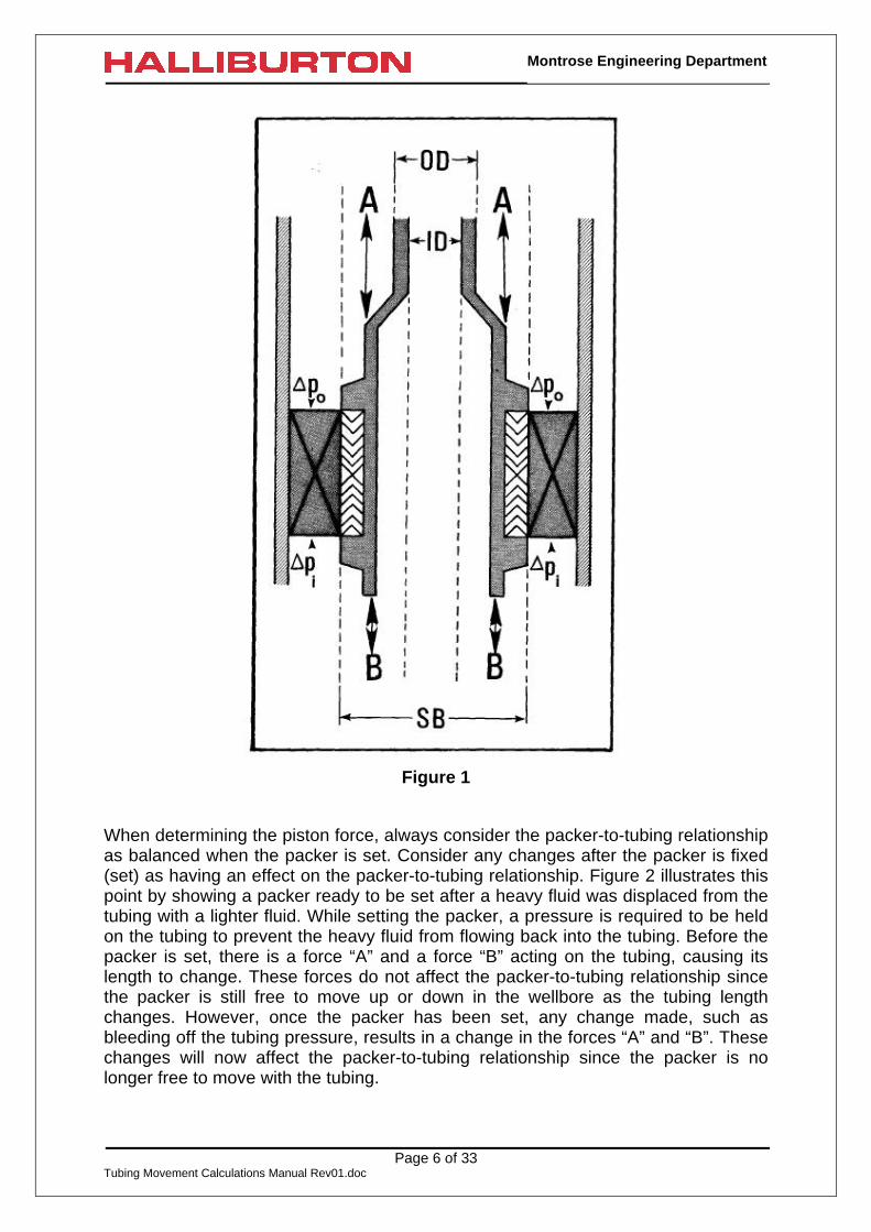
The piston effect is the result of pressure changes inside the tubing string andpressure changes in the casing annulus. The pressure changes inside the tubingstring act on the difference in the areas between the packer valve area (Ap) and thetubing I.D. area (Ai). Pressure changes in the annulus act on the difference in theareas between the packer valve area (Ap) and the tubing O.D. area (Ao). The resultof the piston effect is a force up or down on the end of the tubing string. Because thepiston effect acts only on the bottom of the tubing, it is often referred to as the endarea effect. If the tubing is free to move with respect to the packer, the piston effectwill result in a length change of the tubing. If the tubing is not free to move withrespect to the packer, the piston effect will result in a force change on the packer.
1. PISTON FORCE - F1
In every packer installation, forces “A” and “B” exist as shown in the Figure 1. Theseforces exist even before the packer is set. The result of forces “A” and “B” is calledthe buoyant effect of the fluid on the tubing if the packer is not set. As the tubing andpacker are being run to depth in the well, forces “A” and “B” are increasing andcausing the tubing to shorten. Although the tubing is being shortened by forces “A”and “B”, the packer-to-tubing relationship is not affected since the packer is not set.However, once the packer is set, the effect of a change in tubing pressure or achange in casing pressure is a change in the forces “A” and “B”. These changes inforces “A” and “B”, after the packer is set will also affect the packer-to-tubingrelationship.
Page 6 of 33Tubing Movement Calculations Manual Rev01.doc
Montrose Engineering Department
Figure 1
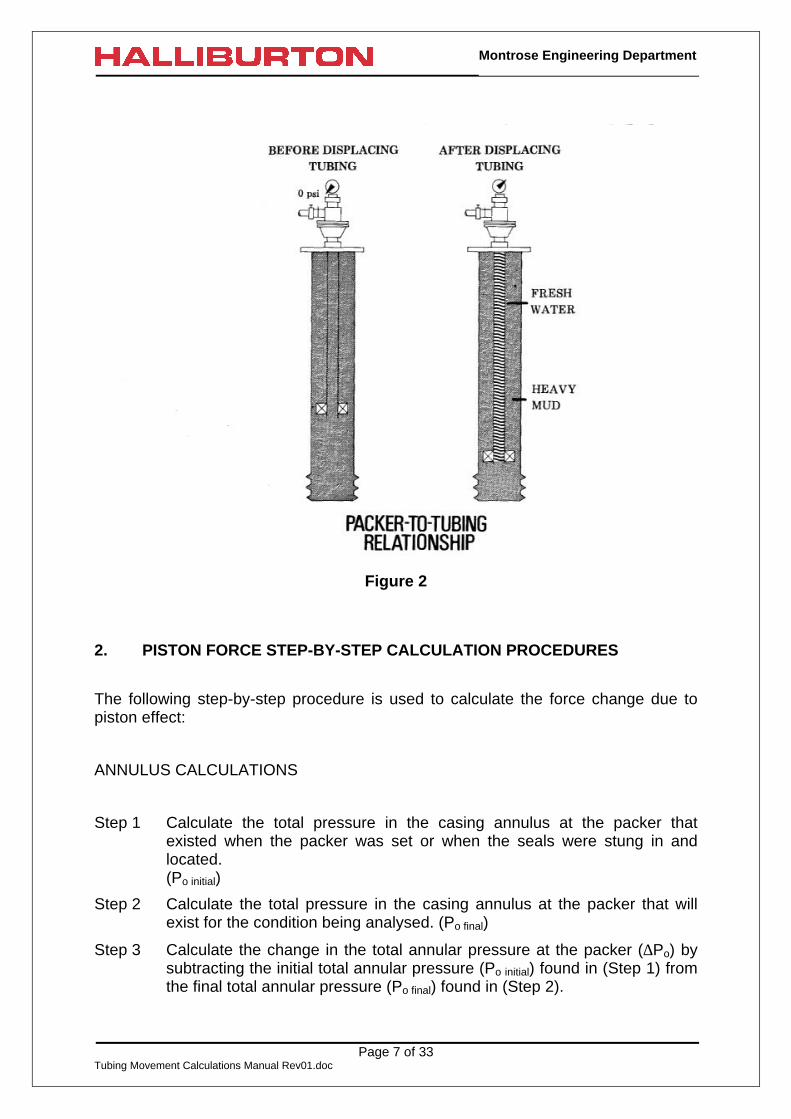
When determining the piston force, always consider the packer-to-tubing relationshipas balanced when the packer is set. Consider any changes after the packer is fixed(set) as having an effect on the packer-to-tubing relationship. Figure 2 illustrates thispoint by showing a packer ready to be set after a heavy fluid was displaced from thetubing with a lighter fluid. While setting the packer, a pressure is required to be heldon the tubing to prevent the heavy fluid from flowing back into the tubing. Before thepacker is set, there is a force “A” and a force “B” acting on the tubing, causing itslength to change. These forces do not affect the packer-to-tubing relationship sincethe packer is still free to move up or down in the wellbore as the tubing lengthchanges. However, once the packer has been set, any change made, such asbleeding off the tubing pressure, results in a change in the forces “A” and “B”. Thesechanges will now affect the packer-to-tubing relationship since the packer is nolonger free to move with the tubing.
Page 7 of 33Tubing Movement Calculations Manual Rev01.doc
Montrose Engineering Department
Figure 2
2. PISTON FORCE STEP-BY-STEP CALCULATION PROCEDURES
The following step-by-step procedure is used to calculate the force change due topiston effect:
ANNULUS CALCULATIONS
Step 1 Calculate the total pressure in the casing annulus at the packer thatexisted when the packer was set or when the seals were stung in andlocated.(Po initial)
Step 2 Calculate the total pressure in the casing annulus at the packer that willexist for the condition being analysed. (Po final)
Step 3 Calculate the change in the total annular pressure at the packer (∆Po) bysubtracting the initial total annular pressure (Po initial) found in (Step 1) fromthe final total annular pressure (Po final) found in (Step 2).

Page 8 of 33Tubing Movement Calculations Manual Rev01.doc
Montrose Engineering Department
Step 4 Subtract the tubing outside area (Ao) from either the packer valve area(Ap), if the packer has a valve, or the packer seal bore area (Ap), if thepacker has a seal bore. If the tubing O.D. is larger than either the packervalve diameter or the packer seal bore diameter (SB), this quantity will benegative.
Step 5 Calculate the change in force “A” by multiplying the change in the totalannular pressure (∆Po) found in (Step 3) times the difference in the areasfound in (Step 4). BE SURE to keep the signs of the numbers correct,since they determine the direction in which the change in force “A” isacting. A negative number means that the change in force “A” is actingupward. If there was no change in the casing pressure between the initialcondition and the condition being analysed, the change in force “A” is zero.
TUBING CALCULATIONS
Step 6 Calculate the total pressure inside the tubing at the packer that existedwhen the packer was set or when the seals were stung in and located.(Pi initial)
Step 7 Calculate the total tubing pressure at the packer that will exist for thecondition being analysed. (Pi final)
Step 8 Calculate the change in the total tubing pressure at the packer (∆Pi) bysubtracting the initial total tubing pressure (Pi initial) found in (Step 6) fromthe final total tubing pressure (Pi final) found in (Step 7).
Step 9 Subtract the tubing inside area (Ai) from either the packer valve area (Ap)or the packer seal bore area (Ap). If the tubing I.D. is larger than either thepacker valve diameter or the packer seal bore diameter (SB), this quantitywill be negative.
Step 10 Calculate the change in force “B” by multiplying the change in tubingpressure (∆Pi) found in (Step 8) times the difference in the areas found in(Step 9). KEEP TRACK of the signs of the numbers since they determinethe direction in which the change in the force “B” is acting. A positivenumber means the change in force “B” is acting upward and a negativenumber means the change in force “B” is acting downward. If there was nochange in the tubing pressure between the initial condition and thecondition being analysed, the change in force “B” is zero.
PISTON FORCE CALCULATIONS
Step 11 - Calculate the piston force “F1” by subtracting the change in the force “B”found in (Step 10) from the change in the force “A” found in (Step 5). Thepiston force units will be pounds (lbs). BE SURE to keep the signs correctin order to know in which direction “F1” is acting. If “F1” is negative, it actsupward on the bottom of the tubing (tension on the packer) and if “F1” is

Page 9 of 33Tubing Movement Calculations Manual Rev01.doc
Montrose Engineering Department
positive, it acts downward on the bottom of the tubing (compression on thepacker).
3. PISTON LENGTH CHANGE - ∆∆L1
If the piston force “F1” (calculated in Step 11 above) acts in a direction in which thepacker permits motion, it will cause a length change (∆L1) in the tubing to occur. Theprocedure used to calculate the length change (∆L1) is the same for both theshortening and the lengthening (elongating) of the tubing.
4. PISTON LENGTH CHANGE STEP-BY-STEP CALCULATIONPROCEDURES
The step-by-step procedure used to find the length change ∆L1 due to the pistonforce is:
Step 1 Determine the piston force (F1). (This force is calculated in (Step 11) of thepreceding step-by-step procedure).
Step 2 Divide the piston force (F1) by the modulus of elasticity, E:(E = 30,000,000 psi for steel)
Step 3 Multiply the value found in (Step 2) by the length of the tubing string (L) ininches. (The length in inches equals the length in feet times 12)
Step 4 Find the tubing cross-sectional area (As) in inches2.
Step 5 Calculate the length change due to the piston effect, ∆L1, by dividing thevalue found in (Step 3) by the tubing cross-sectional area found in (Step4).
5. PISTON EFFECT FORMULAS
Both of the preceding step-by-step procedures may be written in equations. They areas follows:
Piston Force (F1):
( ) ( )[ ] ( ) ( )[ ]initialifinaliipinitialofinaloop1 PPAAPPAAF −×−−−×−=
Writing this in a more condensed form, it becomes:
Page 10 of 33Tubing Movement Calculations Manual Rev01.doc
Montrose Engineering Department
( ) ( )[ ] ( ) ( )[ ]iipoop1 PÄAAPÄAAF ×−−×−=
Piston Length Change (∆L1):
( ) ( ) ( )[ ] ( ) ( )[ ]{ }( ) ( )s
iipoop1 AE
PÄAAPÄAALLÄ
××−−×−×
=
Writing this in terms of the piston force F1, it becomes:
s
11 A
LEF
LÄ ×=
The terms in the above equations are defined as follows:
AI = Area of the tubing I.D. (in2)
Ao = Area of the tubing O.D. (in2)
Ap = Packer valve area or packer seal bore area (in2)
As = Cross-sectional area of the tubing (in2)
E = Modulus of elasticity (30,000,000psi for steel)
F1 = Force change due to the piston effect (lbs)
L = Length of the tubing string in inches (in)
∆L1 = Length change of the tubing string in inches due to the piston forceF1 (in)
∆Pi = Change in the total tubing pressure at the packer (psi)
∆Pi = Pi final - Pi inital
Pi final = Total tubing pressure at the packer that will exist for the conditionbeing analysed (psi)
Pi inital = Total tubing pressure at the packer that existed when the packerwas set or when the seals were stung in and located (psi)
∆Po = Change in the total annular pressure at the packer (psi)
∆Po = Po final – Po inital
Po final = Total annular pressure at the packer that will exist for the conditionbeing analysed (psi)
Po inital = Total annular pressure at the packer that existed when the packerwas set or when the seals were stung in and located (psi)

Page 11 of 33Tubing Movement Calculations Manual Rev01.doc
Montrose Engineering Department
B. BUCKLING EFFECT
The buckling effect is perhaps the most difficult to understand of all the effects. Onereason for this difficulty may be the fact that buckling is caused by two different forcedistributions. They are a compressive force on the end of the tubing and a forcedistribution acting across the tubing wall.
A compressive force acting on the end of the tubing is one of the force distributionsthat will cause tubing to buckle. When a compressive force is applied to a long limbertubing string, it is easy to visualize that the force will cause the tubing to buckle. Anexample of this is tubing that is stacked in the derrick. The stacked tubing will buckleor bow out due to its own weight.
The other force distribution causing the tubing to buckle is more difficult to visualize.Tubing will also buckle due to a force distribution created by a larger pressure insidethe tubing than the pressure on the outside of the tubing. The pressure inside thetubing creates a force distribution that acts on the inside area of the tubing while theoutside pressure creates a force distribution that acts on the outside area of thetubing. Since the pressure inside the tubing is higher than the pressure outside thetubing, these force distributions will produce burst stresses in the tubing. The wallthickness of tubing used in the oilfield will vary along the length of the tubing. Tubingcannot be manufactured in the lengths required for use in oil wells without havingwall thickness variations. Since the wall thickness is not constant, the burst stressescan not equally distribute themselves in the tubing. The unequal burst stressdistribution will cause the tubing to buckle.
1. UNDERSTANDING THE BUCKLING EFFECT
Before the procedure for calculating the buckling effect is explained, the followingstatements about the buckling effect must be understood.
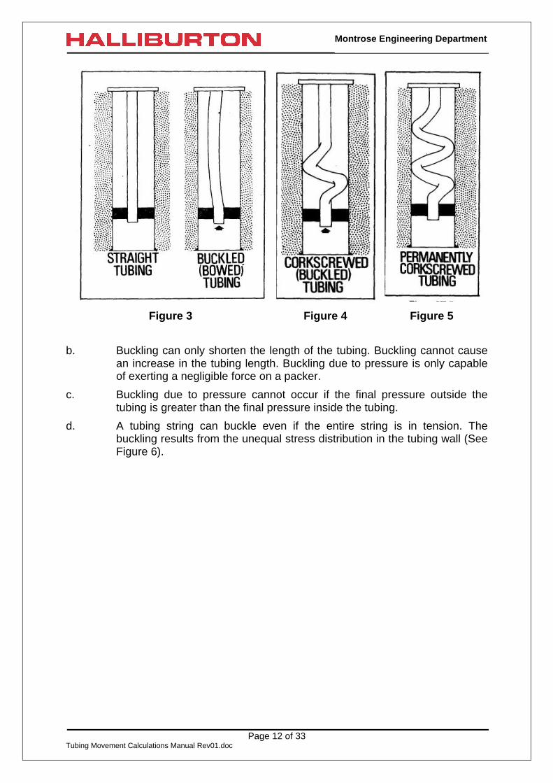
a. Buckled tubing is tubing that is bowed from its original straight up anddown condition (See Figure 3). In a buckling condition, the tubing willcontinue to bow out until it contacts the casing wall. When this contact ismade, the tubing will begin to coil. This coiling of the tubing is referred toas “corkscrewing” the tubing. As shown in Figure 4, corkscrewed tubing isa form of buckled tubing. As long as the stresses in the tubing producedfrom buckling do not exceed the yield strength of the tubing, the tubing willreturn to its original shape when the force causing the buckling is removed.When the stresses due to buckling exceed the yield strength of the tubing,permanent corkscrewing, as shown in Figure 5 will take place. When thetubing is permanently cork-screwed, the tubing will not return to its originalshape when the force causing the buckling is removed.
Page 12 of 33Tubing Movement Calculations Manual Rev01.doc
Montrose Engineering Department
Figure 3 Figure 4 Figure 5
b. Buckling can only shorten the length of the tubing. Buckling cannot causean increase in the tubing length. Buckling due to pressure is only capableof exerting a negligible force on a packer.
c. Buckling due to pressure cannot occur if the final pressure outside thetubing is greater than the final pressure inside the tubing.
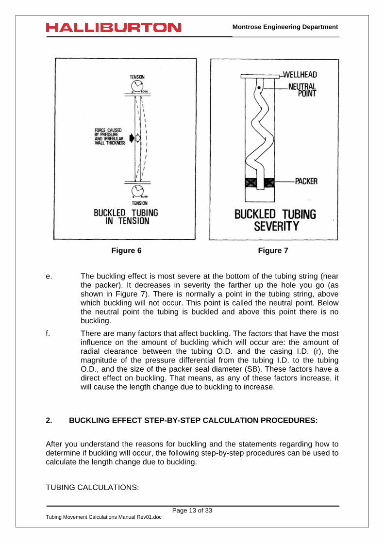
d. A tubing string can buckle even if the entire string is in tension. Thebuckling results from the unequal stress distribution in the tubing wall (SeeFigure 6).
Page 13 of 33Tubing Movement Calculations Manual Rev01.doc
Montrose Engineering Department
Figure 6 Figure 7
e. The buckling effect is most severe at the bottom of the tubing string (nearthe packer). It decreases in severity the farther up the hole you go (asshown in Figure 7). There is normally a point in the tubing string, abovewhich buckling will not occur. This point is called the neutral point. Belowthe neutral point the tubing is buckled and above this point there is nobuckling.
f. There are many factors that affect buckling. The factors that have the mostinfluence on the amount of buckling which will occur are: the amount ofradial clearance between the tubing O.D. and the casing I.D. (r), themagnitude of the pressure differential from the tubing I.D. to the tubingO.D., and the size of the packer seal diameter (SB). These factors have adirect effect on buckling. That means, as any of these factors increase, itwill cause the length change due to buckling to increase.
2. BUCKLING EFFECT STEP-BY-STEP CALCULATION PROCEDURES:
After you understand the reasons for buckling and the statements regarding how todetermine if buckling will occur, the following step-by-step procedures can be used tocalculate the length change due to buckling.
TUBING CALCULATIONS:

Page 14 of 33Tubing Movement Calculations Manual Rev01.doc
Montrose Engineering Department
Step 1 Calculate the total pressure inside the tubing at the packer that existedwhen the packer was set or when the seals were stung in and located(Pi initial).
Step 2 Calculate the total pressure inside the tubing at the packer that will exist forthe condition being analyzed (Pi final)
Step 3 Subtract the initial total tubing pressure (Pi initial) found in (Step 1) from thefinal total tubing pressure (Pi final) found in (Step 2). This result is thechange in the total tubing pressure (∆Pi).
ANNULUS CALCULATIONS:
Step 4 Calculate the total annular pressure at the packer that existed when thepacker was set or when the seals were stung in and located (Po initial)
Step 5 Calculate the total annular pressure at the packer that will exist for thecondition being analyzed (Po final)
Step 6 Subtract the initial total annular pressure (Po initial) found in (Step 4) fromthe final total annular pressure (Po final)found in (Step 5). This result is thechange in the total annular pressure (∆Po).
BUCKLING CALCULATIONS:
Step 7 Subtract the change in the total annular pressure (∆Po).found in (Step 6)from the change in the total tubing pressure (∆Pi).found in (Step 3). Thissubtracting must result in a positive answer or buckling will not occur. Thatmeans, the length change due to buckling (∆L2) is zero and (Steps 8through 23) can be skipped.
Step 8 Square the result found in (Step 7). (Remember to square a number,multiply it times itself).
Step 9 Calculate the area of the packer seal bore (Ap) in square inches.
Step 10 Square the packer seal bore area found in (Step 9).
Step 11 Determine the radial clearance (r) between the tubing O.D. and the casingI.D. in inches (See Figure VI-8). The radial clearance is found bysubtracting the tubing O.D. from the casing I.D., then dividing the quantityfound by (2.0).
( )2
ODTubingIDgsinCar
−=

Page 15 of 33Tubing Movement Calculations Manual Rev01.doc
Montrose Engineering Department
Figure 8
Step 12 Square the radial clearance found in (Step 11).
Step 13 Divide the square of the pressure change difference (Step 8) by themodulus of elasticity, (E). (E = 30,000,000 psi for steel)
Step 14 Multiply the square of the radial clearance found in (Step 12) times thesquare of the packer seal bore area found in (Step 10) times the valuefound in (Step 13).
Step 15 Calculate the moment of inertia (I) for the tubing size being used.( ) ( )[ ]
64IDODð
I44 −
=
Step 16 Calculate the “Tubing Weight Factors,” Ws, W i, and Wo,
W i = Weight of the fluid displaced in the tubing per unit length (lbs/in)
WI (lbs/in) = 0.0034 x (Tbg ID)2 x (Fin. Tbg. Fluid Wt. in lbs/gal)
W = Weight of the final outside fluid displaced per unit length (lbs/in)
Wo (lbs/in) = 0.0034 x (Tbg OD)2 x (Fin. Ann. Fluid Wt. in lbs/gal)
Ws = Weight of the tubing in lbs per inch (lbs/in)
Add Ws and W i together. Then, subtract Wo from this quantity. This resultis the adjusted weight of the tubing in pounds per inch.
Adjusted Tbg Wt (lbs/in)= Ws (lbs/in) + W i (lbs/in) - Wo W0 (lbs/in)
Step 17 Multiply the adjusted tubing weight found in (Step 16) times the moment ofinertia (I) found in (Step 15) times (-8.0).
Step 18 Calculate the length change due to buckling, (∆L2) by dividing the resultfound in (Step 14) by the result found in (Step 17).
Page 16 of 33Tubing Movement Calculations Manual Rev01.doc
Montrose Engineering Department
The answer is the length in inches the tubing will shorten as a result of buckling. Thelength change due to buckling will always be a negative number.
NEUTRAL POINT CALCULATIONS;
Step 19 Subtract Po final (Step 5) from Pi final (Step 2), then multiply this value by Ap
(Step 9).
Step 20 Calculate the neutral point by dividing the result found in (Step 19) by theresult found in (Step 16). The value obtained represents the distance ininches from the packer to the neutral point. (Remember, the neutral pointis the point in the tubing string below which buckling exists andabove which there is no buckling.)
If the distance from the packer to the neutral point calculated in (Step 20) is largerthan the entire length of the tubing string in inches (L), the length change due tobuckling (∆L2) is different than what was calculated in (Step 18) and it must becorrected. The length change due to buckling is corrected by completing (Steps 21through 23). If the distance from the packer to the neutral point is less than the entirelength of the tubing string in inches (L), the length change due to buckling (∆L2)calculated in (Step 18) is correct and the (Steps 21 through 23) will be skipped.When the distance from the packer to the neutral point is larger than the length ofthe tubing string, the entire length of the tubing string is buckled and the correctedlength change due to buckling (∆L2’) must be calculated.
Step 21 Divide the length of the tubing in inches (L) by the result found in (Step20).
Step 22 Subtract the result found in (Step 21) from (2.0).
Step 23 Calculate the corrected length change due to buckling (∆L2’) by multiplyingthe result found in (Step 22) times the result found in (Step 21) times thelength change due to buckling (∆L2) found in (Step 18). The value obtainedis in inches.
3. BUCKLING EFFECT FORMULAS:
All the preceding step-by-step procedures for calculating the length change due tobuckling may be written as the following formulas:
Length Change Due to Buckling (∆L2):
Page 17 of 33Tubing Movement Calculations Manual Rev01.doc
Montrose Engineering Department
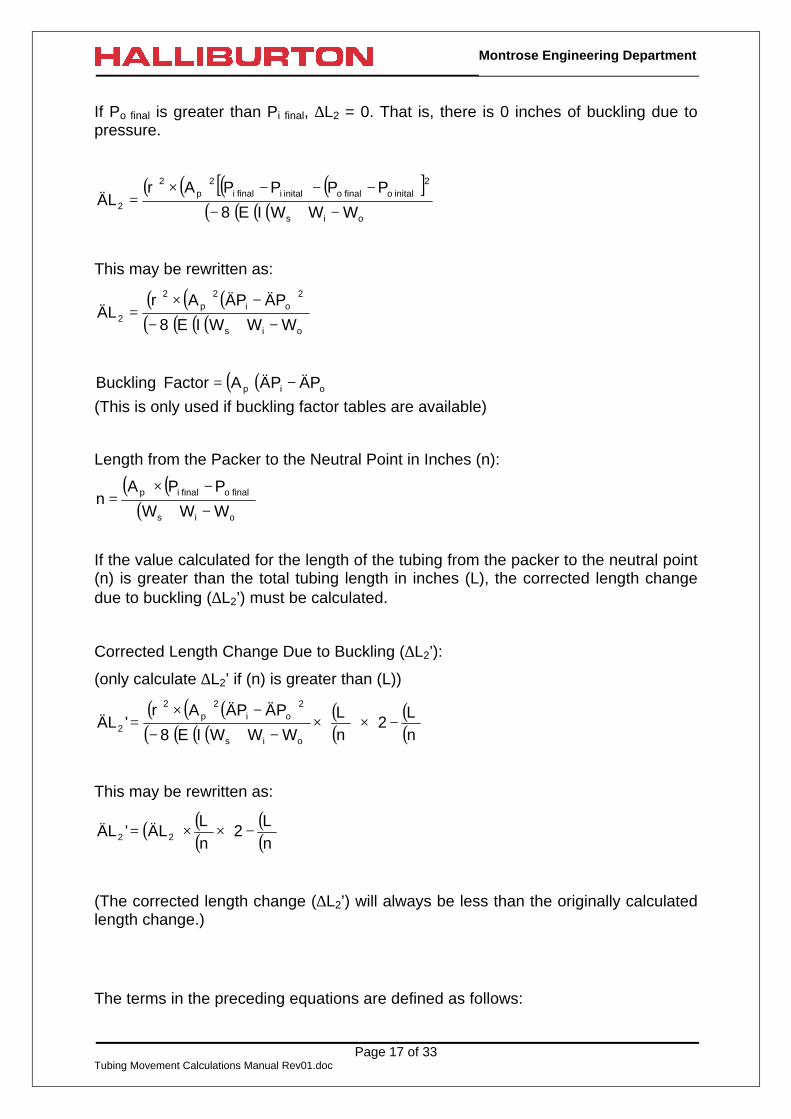
If Po final is greater than Pi final, ∆L2 = 0. That is, there is 0 inches of buckling due topressure.
( ) ( ) ( ) ( )[ ]( )( )( )( )ois
2initalofinaloinitalifinali
2p
2
2 WWWIE8
PPPPArLÄ
−+−
−−−×=
This may be rewritten as:
( ) ( ) ( )( )( )( )( )ois
2oi
2p
2
2 WWWIE8
PÄPÄArLÄ
−+−
−×=
( )( )oip PÄPÄA Factor Buckling −=(This is only used if buckling factor tables are available)
Length from the Packer to the Neutral Point in Inches (n):
( ) ( )( )ois
finalofinalip
WWW
PPAn
−+
−×=
If the value calculated for the length of the tubing from the packer to the neutral point(n) is greater than the total tubing length in inches (L), the corrected length changedue to buckling (∆L2’) must be calculated.
Corrected Length Change Due to Buckling (∆L2’):
(only calculate ∆L2’ if (n) is greater than (L))
( ) ( ) ( )( )( )( )( )
( )( )
( )( )
−×
×
−+−
−×=
nL
2nL
WWWIE8
PÄPÄAr'LÄ
ois
2oi
2p
2
2
This may be rewritten as:
( ) ( )( )
( )( )
−××=
nL
2nL
LÄ'LÄ 22
(The corrected length change (∆L2’) will always be less than the originally calculatedlength change.)
The terms in the preceding equations are defined as follows:

Page 18 of 33Tubing Movement Calculations Manual Rev01.doc
Montrose Engineering Department
Ap = Packer valve area or packer seal bore area (in2)
E = Modulus of elasticity (30,000,000psi for steel)
I = Moment of inertia of the tubing (in4).
( ) ( )[ ]64
IDODðI
44 −=
L = Length of the tubing (in)
∆L2 = Length change in inches due to buckling (in)
∆L2’ = Length change in inches due to buckling when the neutral point isabove the top of the tubing. (in)
n = The distance from the packer to the neutral point in inches. It. is alsocalled the length of buckled tubing. (in)
∆Pi = Change in the total tubing pressure at the packer (psi)
∆Pi = Pi final - Pi inital
Pi final = Total tubing pressure at the packer that will exist for the conditionbeing analysed (psi)
Pi inital = Total tubing pressure at the packer that existed when the packerwas set or when the seals were stung in and located (psi)
∆Po = Change in the total annular pressure at the packer (psi)
∆Po = Po final – Po inital
Po final = Total annular pressure at the packer that will exist for the conditionbeing analysed (psi)
Po inital Total annular pressure at the packer that existed when the packerwas set or when the seals were stung in and located (psi)
r = Radial clearance between the casing I.D. and the tubing O.D. (in)
2ODTubingIDgsinCa
r−
=
W i = Weight of the fluid displaced in the tubing per unit length (lbs/in)
WI (lbs/in) = 0.0034 x (Tbg ID)2 x (Fin. Tbg. Fluid Wt. in lbs/gal)
Wo = Weight of the final outside fluid displaced per unit length (lbs/in)
Wo (lbs/in) = 0.0034 x (Tbg OD)2 x (Fin. Ann. Fluid Wt. in lbs/gal)
Ws = Weight of the tubing in lbs per inch (lbs/in)
Note: The above calculations did not solve for a force due to buckling, sincebuckling due to pressure can only exert a negligible force.
Page 19 of 33Tubing Movement Calculations Manual Rev01.doc
Montrose Engineering Department
C. BALLOONING EFFECT
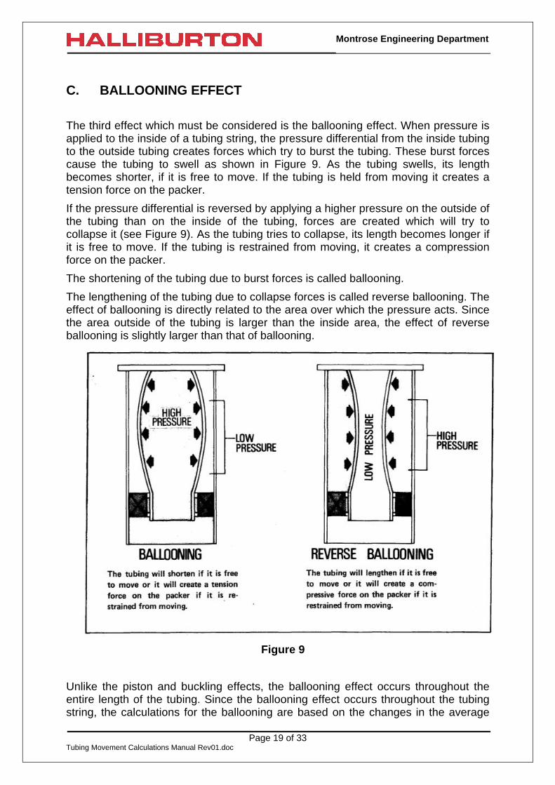
The third effect which must be considered is the ballooning effect. When pressure isapplied to the inside of a tubing string, the pressure differential from the inside tubingto the outside tubing creates forces which try to burst the tubing. These burst forcescause the tubing to swell as shown in Figure 9. As the tubing swells, its lengthbecomes shorter, if it is free to move. If the tubing is held from moving it creates atension force on the packer.
If the pressure differential is reversed by applying a higher pressure on the outside ofthe tubing than on the inside of the tubing, forces are created which will try tocollapse it (see Figure 9). As the tubing tries to collapse, its length becomes longer ifit is free to move. If the tubing is restrained from moving, it creates a compressionforce on the packer.
The shortening of the tubing due to burst forces is called ballooning.
The lengthening of the tubing due to collapse forces is called reverse ballooning. Theeffect of ballooning is directly related to the area over which the pressure acts. Sincethe area outside of the tubing is larger than the inside area, the effect of reverseballooning is slightly larger than that of ballooning.
Figure 9
Unlike the piston and buckling effects, the ballooning effect occurs throughout theentire length of the tubing. Since the ballooning effect occurs throughout the tubingstring, the calculations for the ballooning are based on the changes in the average
Page 20 of 33Tubing Movement Calculations Manual Rev01.doc
Montrose Engineering Department
pressures on both the inside and the outside of the tubing. Because the averagepressure is based on the surface pressure plus the pressure at the packer,increasing the bottom hole pressure by changing the fluid gradient would only havehalf the effect of making the same change by applying added surface pressure.
It is possible for well conditions to affect the average pressure both inside andoutside the tubing, so the ballooning and reverse ballooning effects are calculatedtogether. Ballooning can cause either a force or a length change depending on thetubing ability to move at the packer.
1. BALLOONING FORCE (F3) STEP-BY-STEP CALCULATION PROCEDURES
The following is a step-by-step procedure for determining the force changes (F3) dueto ballooning.
TUBING CALCULATIONS:
Step 1 Determine the surface pressure inside the tubing that existed when thepacker was set or when the seals were stung in and located. (InitialApplied Tubing Pressure)
Step 2 Calculate the total pressure inside the tubing at the packer that existedwhen the packer was set or when the seals were stung in and located.(Pi initial)
Step 3 Calculate the initial average pressure inside the tubing by adding the initialapplied tubing pressure found in (Step 1) to the initial total tubing pressureat the packer (Pi initial) found in (Step 2) and then divide this value by 2.
( )2
PessPrTbgAppliedInitialessPrTbgAvgInitial initial i+
=
Step 4 Determine the surface pressure inside the tubing that will exist for thecondition being analyzed. (Final Applied Tubing Pressure).
Step 5 Calculate the total pressure inside the tubing at the packer that will exist forthe condition being analyzed. (Pi final)
Step 6 - Calculate the final average pressure inside of the tubing by adding to thefinal applied tubing pressure found in (Step 4) to the final total tubingpressure at the packer (Pi final) found in (Step 5), and then divide this valueby 2.
( )2
PessPrTbgAppliedFinalessPrTbgAvgFinal final i+
=
Step 7 - Calculate the change in average tubing pressure (∆Pia) by subtracting theinitial average tubing pressure found in (Step 3) from the final averagetubing pressure found in (Step 6).
∆Pia = (Final Avg Tbg Press) — (Initial Avg Tbg Press)

Page 21 of 33Tubing Movement Calculations Manual Rev01.doc
Montrose Engineering Department
ANNULUS CALCULATIONS:
Step 8 Determine the surface pressure in the annulus that existed when thepacker was set or when the seals were stung in and located. (InitialApplied Annular Pressure)
Step 9 - Calculate the total annular pressure at the packer that existed when thepacker was set or when the seals were stung in and located. (Po initial)
Step 10 - Calculate the initial average pressure in the annulus by adding the initialapplied annular pressure found in (Step 8) to the initial annular pressure atthe packer (Po initial) found in (Step 9) and then divide this value by 2.
( )2
PessPrAnnularAppliedInitialessPrAnnularAvgInitial initial o+
=
Step 11 Determine the surface pressure in the annulus that exists for the conditionbeing analyzed. (Final Applied Annular Pressure)
Step 12 Calculate the total final annular pressure at the packer that exists for thecondition being analyzed. (Po final)
Step 13 - Calculate the final average pressure in the annulus by adding the finalapplied annular pressure found in (Step 11) to the final total annularpressure at the packer (Po final) found in (Step 12), and then divide thisvalue by 2.
( )2
PessPrAnnularAppliedFinalessPrAnnularAvgFinal final o+
=
Step 14 Calculate the change in average annular pressure, (∆Poa), by subtractingthe initial average annular pressure found in (Step 10) from the finalaverage annular pressure found in (Step 13).
( ) ( )essPrAnnularAvgInitessPrAnnularAvgFinalPÄ oa −=
BALLOONING EFFECT (F3) CALCULATIONS:
Step 15 Find the area of the inside of the tubing. (Ai)
Step 16 Multiply the inside area of the tubing (Ai) found in (Step 15) times thechange in average tubing pressure, (∆Pia), found in (Step 7).
Step 17 Find the area of the outside of the tubing. (Ao)
Page 22 of 33Tubing Movement Calculations Manual Rev01.doc
Montrose Engineering Department
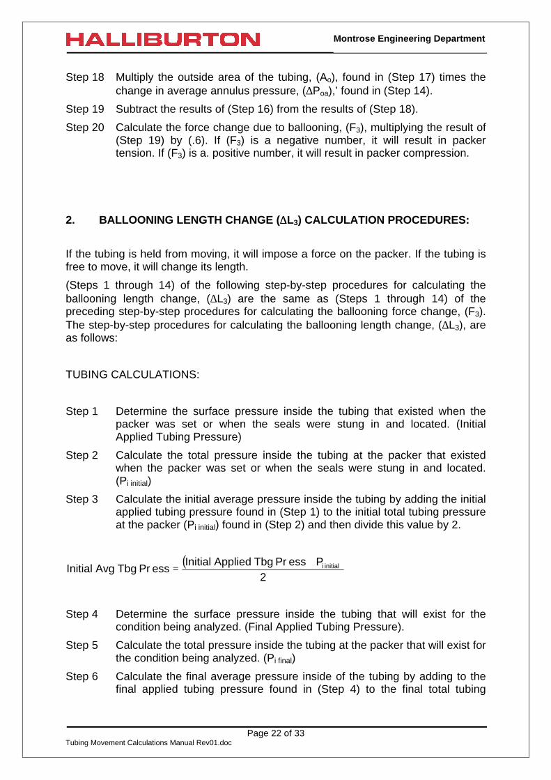
Step 18 Multiply the outside area of the tubing, (Ao), found in (Step 17) times thechange in average annulus pressure, (∆Poa),’ found in (Step 14).
Step 19 Subtract the results of (Step 16) from the results of (Step 18).
Step 20 Calculate the force change due to ballooning, (F3), multiplying the result of(Step 19) by (.6). If (F3) is a negative number, it will result in packertension. If (F3) is a. positive number, it will result in packer compression.
2. BALLOONING LENGTH CHANGE (∆∆L3) CALCULATION PROCEDURES:
If the tubing is held from moving, it will impose a force on the packer. If the tubing isfree to move, it will change its length.
(Steps 1 through 14) of the following step-by-step procedures for calculating theballooning length change, (∆L3) are the same as (Steps 1 through 14) of thepreceding step-by-step procedures for calculating the ballooning force change, (F3).The step-by-step procedures for calculating the ballooning length change, (∆L3), areas follows:
TUBING CALCULATIONS:
Step 1 Determine the surface pressure inside the tubing that existed when thepacker was set or when the seals were stung in and located. (InitialApplied Tubing Pressure)
Step 2 Calculate the total pressure inside the tubing at the packer that existedwhen the packer was set or when the seals were stung in and located.(Pi initial)
Step 3 Calculate the initial average pressure inside the tubing by adding the initialapplied tubing pressure found in (Step 1) to the initial total tubing pressureat the packer (Pi initial) found in (Step 2) and then divide this value by 2.
( )2
PessPrTbgAppliedInitialessPrTbgAvgInitial initial i+
=
Step 4 Determine the surface pressure inside the tubing that will exist for thecondition being analyzed. (Final Applied Tubing Pressure).
Step 5 Calculate the total pressure inside the tubing at the packer that will exist forthe condition being analyzed. (Pi final)
Step 6 Calculate the final average pressure inside of the tubing by adding to thefinal applied tubing pressure found in (Step 4) to the final total tubing

Page 23 of 33Tubing Movement Calculations Manual Rev01.doc
Montrose Engineering Department
pressure at the packer (Pi final) found in (Step 5), and then divide this valueby 2.
( )2
PessPrTbgAppliedFinalessPrTbgAvgFinal final i+
=
Step 7 Calculate the change in average tubing pressure (∆Pia) by subtracting theinitial average tubing pressure found in (Step 3) from the final averagetubing pressure found in (Step 6).
∆Pia = (Final Avg Tbg Press) — (Initial Avg Tbg Press)
ANNULUS CALCULATIONS:
Step 8 Determine the surface pressure in the annulus that existed when thepacker was set or when the seals were stung in and located. (InitialApplied Annular Pressure)
Step 9 Calculate the total annular pressure at the packer that existed when thepacker was set or when the seals were stung in and located. (Po initial)
Step 10 Calculate the initial average pressure in the annulus by adding the initialapplied annular pressure found in (Step 8) to the initial annular pressure atthe packer (Po initial) found in (Step 9) and then divide this value by 2.
( )2
PessPrAnnularAppliedInititalessPrAnnularAvgInitital initial o+
=
Step 11 Determine the surface pressure in the annulus that exists for the conditionbeing analyzed. (Final Applied Annular Pressure)
Step 12 Calculate the total final annular pressure at the packer that exists for thecondition being analyzed. (Po final)
Step 13 Calculate the final average pressure in the annulus by adding the finalapplied annular pressure found in (Step 11) to the final total annularpressure at the packer (Po final) found in (Step 12), and then divide thisvalue by 2.
( )2
PessPrAnnularAppliedFinalessPrAnnularAvgFinal final o+
=

Page 24 of 33Tubing Movement Calculations Manual Rev01.doc
Montrose Engineering Department
Step 14 Calculate the change in average annular pressure, (∆Poa), by subtractingthe initial average annular pressure found in (Step 10) from the finalaverage annular pressure found in (Step 13).
BALLOONING EFFECT (∆L3) CALCULATIONS:
Step 15 - Find the outside diameter of the tubing.
Step 16 - Find the inside diameter of the tubing.
Step 17 - Find the ratio, (R), of the tubing O.D. to the tubing I.D. by dividing thetubing outside diameter found in (Step 15) by the tubing inside diameterfound in (Step 16). The ratio, R, will always be a number greater than 1.
IDTubingODTubing
R =
Step 18 Square the ratio R.
Step 19 Multiply the change in average annular pressure (∆Poa) found in (Step 14)by R2 found in (Step 18).
Step 20 Subtract the change in average tubing pressure, (∆Pia), found in (Step 7)from the result of (Step 19).
Step 21 Subtract 1.0 from the result found in (Step 18).
Step 22 Divide the result found in (Step 20) by the result found in (Step 21).
Step 23 Calculate the length of the tubing string in inches.
Step 24 Multiply the length of the tubing in inches found in (Step 23) by (-0.2) andthen divide this quantity by 10,000,000 psi.
Step 25 Calculate the length change due to ballooning in inches, (∆L3), bymultiplying the result found in (Step 22) by the result found in (Step 24). If∆L3 is a negative number, the tubing will shorten. If ∆L3 is a positivenumber, the tubing will elongate.
3. BALLOONING EFFECT FORMULAS
The preceding step-by-step procedures for calculating the ballooning effects may bewritten as the following formulas:
BALLOONING FORCE (F3):

Page 25 of 33Tubing Movement Calculations Manual Rev01.doc
Montrose Engineering Department
( ) ( )[ ]iiaooa3 APÄAPÄ6.0F −=
CHANGE IN THE TUBING LENGTH, (∆L3), DUE TO THE BALLOONING FORCE:
−−
×
×
=1R
PÄPÄR
000,000,10L2.0
LÄ2
iaoa2
3
This may be rewritten as:
−−
×
××
=1R
PÄPÄR
101L2.0
LÄ2
iaoa2
73
The terms used in the formulas are defined as follows:
Ai = Area of the tubing ID (in2)
Ao = Area of the tubing OD (in2)
F3 = Force change due to the ballooning effect. (lbs)
L = Length of the tubing in inches (in)
∆L3 = Length change of the tubing string in inches due to the ballooningforce. (F3) (in)
∆Pia = Change in the average tubing pressure. (psi)
Where:( ) ( )
+
−
+
=2
PessPrTbgAppliedInitial2
PessPrTbgAppliedFinalPÄ initial ifinal i
ia
Pi final = Total tubing pressure at the packer that will exist for the conditionbeing analysed (psi)
Pi inital = Total tubing pressure at the packer that existed when the packerwas set or when the seals were stung in and located (psi)
∆Poa = Change in the average annular pressure (psi)
Where:( ) ( )
+−
+=
2
PessPrAnnularAppliedInitial
2
PessPrAnnularAppliedFinalPÄ initial ofinal o
oa
Po final = Total annular pressure at the packer that will exist for the conditionbeing analysed (psi)
Po inital Total annular pressure at the packer that existed when the packerwas set or when the seals were stung in and located (psi)
R = Ratio of the tubing O.D. to the tubing I.D.

Page 26 of 33Tubing Movement Calculations Manual Rev01.doc
Montrose Engineering Department
IDTubingODTubing
R =

Page 27 of 33Tubing Movement Calculations Manual Rev01.doc
Montrose Engineering Department
D. TEMPERATURE EFFECT
The fourth basic effect is the temperature effect. The temperature effect is the onlyone of the four basic effects that is not pressure related. The length and forcechanges due to the temperature effect are only functions of the change in theaverage temperature of the tubing.
When an object is heated, it will grow in size. On the other hand, if an object iscooled, it will shrink in size. (See Figure 10) A couple of examples to show the effectof changing an object’s temperature follow: When removing a pulley from a shaft, thepulley can be heated causing it to expand. This expansion (or growth) will allow easyremoval of the pulley from the shaft. Another example is dipping a person’s hand incold water so that a ring can be removed. The cold water will shrink the person’shand allowing the ring to be removed easier.
These same principles of expansion and contraction also hold true when the averagetubing temperature is increased or decreased. When an average tubing temperatureis decreased (by injecting cool fluids), it will either shorten in length if the tubing isfree to move or it will create tension force on the packer if the tubing is restrainedfrom moving. When the average tubing temperature is increased, (by either injectinghot fluids or producing hot fluids), it will either cause the tubing to elongate if it is freeto move or it will create a compressive force on the packer if it is held from moving.In many packer installations the temperature effect will be the largest of the fourbasic effects.
Figure 10
Page 28 of 33Tubing Movement Calculations Manual Rev01.doc
Montrose Engineering Department
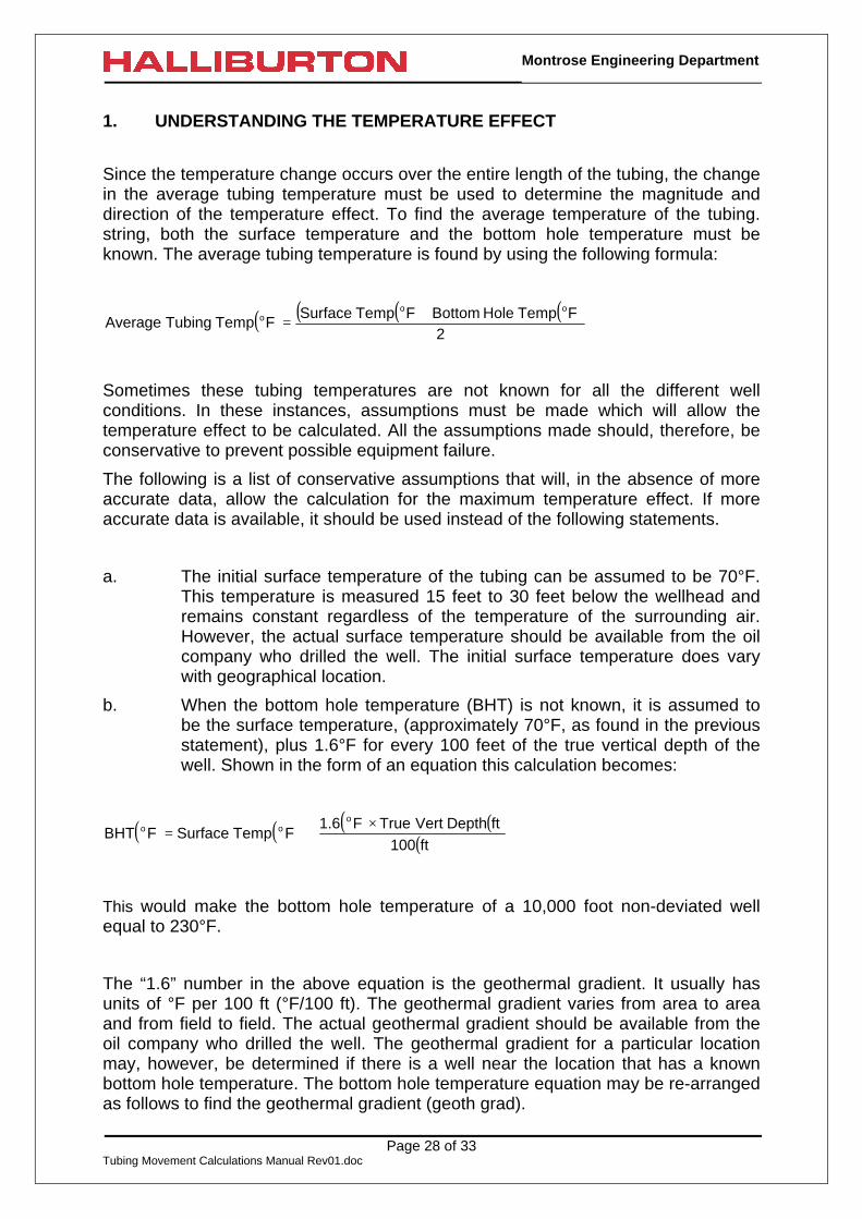
1. UNDERSTANDING THE TEMPERATURE EFFECT
Since the temperature change occurs over the entire length of the tubing, the changein the average tubing temperature must be used to determine the magnitude anddirection of the temperature effect. To find the average temperature of the tubing.string, both the surface temperature and the bottom hole temperature must beknown. The average tubing temperature is found by using the following formula:
( ) ( ) ( )( )2
FTempHoleBottomFTempSurfaceFTempTubingAverage
ooo +
=
Sometimes these tubing temperatures are not known for all the different wellconditions. In these instances, assumptions must be made which will allow thetemperature effect to be calculated. All the assumptions made should, therefore, beconservative to prevent possible equipment failure.
The following is a list of conservative assumptions that will, in the absence of moreaccurate data, allow the calculation for the maximum temperature effect. If moreaccurate data is available, it should be used instead of the following statements.
a. The initial surface temperature of the tubing can be assumed to be 70°F.This temperature is measured 15 feet to 30 feet below the wellhead andremains constant regardless of the temperature of the surrounding air.However, the actual surface temperature should be available from the oilcompany who drilled the well. The initial surface temperature does varywith geographical location.
b. When the bottom hole temperature (BHT) is not known, it is assumed tobe the surface temperature, (approximately 70°F, as found in the previousstatement), plus 1.6°F for every 100 feet of the true vertical depth of thewell. Shown in the form of an equation this calculation becomes:
( ) ( ) ( ) ( )( )
×+=
ft100ftDepthVertTrueF6.1
FTempSurfaceFBHTo
oo
This would make the bottom hole temperature of a 10,000 foot non-deviated wellequal to 230°F.
The “1.6” number in the above equation is the geothermal gradient. It usually hasunits of °F per 100 ft (°F/100 ft). The geothermal gradient varies from area to areaand from field to field. The actual geothermal gradient should be available from theoil company who drilled the well. The geothermal gradient for a particular locationmay, however, be determined if there is a well near the location that has a knownbottom hole temperature. The bottom hole temperature equation may be re-arrangedas follows to find the geothermal gradient (geoth grad).

Page 29 of 33Tubing Movement Calculations Manual Rev01.doc
Montrose Engineering Department
( ) ( ) ( ) ( )( )
−×=
ftDepthVertTrueFTempSurfaceFBHT
ft100ft100/FGradGeothoo
o
When working with the geothermal gradient, it is assumed the temperature from thesurface to the true vertical depth will increase uniformly.
c. The tubing temperature is assumed to be the same temperature as eitherthe fluid that surrounds it, if the well is static, or the fluid that passesthrough it, if there is fluid movement (injection or production).
d. The temperature of the injected fluid that is not heated is assumed to bethe same as the current air temperature at the wellsite.
e. When injecting fluids, assume that the entire length of the tubing is cooledor heated to the temperature of the injected fluid.
f. When producing fluids, the entire length of the tubing can be assumed tobe the same temperature as the initial bottom hole temperature.
g. In a dual packer installation, the primary string and the secondary stringare treated separately. The previous temperature statements about theinjection, producing, or static conditions are applied to both the primarystring and secondary string separately.
By making these assumptions, the temperature effect magnitude and direction canbe calculated. When accurate well data is available, it should be used instead of theassumptions presented.
Two important points about the temperature effect should be kept in mind whenequipment is installed downhole. The first point is that the temperature effect is notfelt immediately at the packer. When pressure changes occur, their effect is feltimmediately at the packer while the temperature effect can require anywhere fromseveral. minutes to several hours to change. However, it is normally assumed thatthe temperature effect does occur immediately. This assumption allows thetemperature effect to be added to the pressure effects so that all the effects can beconsidered at one time. In some situations this assumption can create problemsresulting in equipment failure if it is required that the temperature effect occursimmediately in order for the installation to operate properly.
The second point is that in injection situations, the temperature of the injected fluidwill vary with time as a result of climatic changes. When an installation is plannedwhere the injection temperatures will vary, the average temperature calculation mustbe based on the worst case of the injection temperature. Cold winter nights havebeen responsible for packer failures. When the temperature drops at night, theinjection fluid temperature also decreases (See Statement d on page 29) causing atension force or a tubing shrinkage which may not have been considered.
Page 30 of 33Tubing Movement Calculations Manual Rev01.doc
Montrose Engineering Department
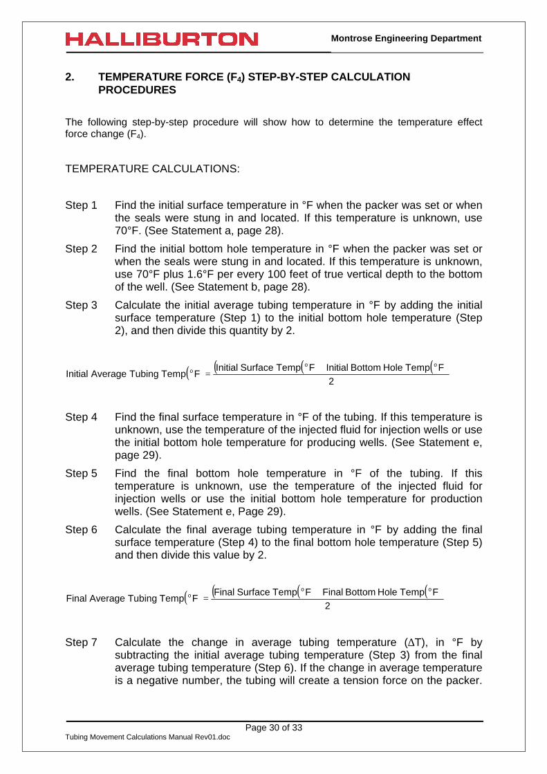
2. TEMPERATURE FORCE (F4) STEP-BY-STEP CALCULATIONPROCEDURES
The following step-by-step procedure will show how to determine the temperature effectforce change (F4).
TEMPERATURE CALCULATIONS:
Step 1 Find the initial surface temperature in °F when the packer was set or whenthe seals were stung in and located. If this temperature is unknown, use70°F. (See Statement a, page 28).
Step 2 Find the initial bottom hole temperature in °F when the packer was set orwhen the seals were stung in and located. If this temperature is unknown,use 70°F plus 1.6°F per every 100 feet of true vertical depth to the bottomof the well. (See Statement b, page 28).
Step 3 Calculate the initial average tubing temperature in °F by adding the initialsurface temperature (Step 1) to the initial bottom hole temperature (Step2), and then divide this quantity by 2.
( ) ( ) ( )( )2
FTempHoleBottomInitialFTempSurfaceInitialFTempTubingAverageInitial
ooo +
=
Step 4 Find the final surface temperature in °F of the tubing. If this temperature isunknown, use the temperature of the injected fluid for injection wells or usethe initial bottom hole temperature for producing wells. (See Statement e,page 29).
Step 5 Find the final bottom hole temperature in °F of the tubing. If thistemperature is unknown, use the temperature of the injected fluid forinjection wells or use the initial bottom hole temperature for productionwells. (See Statement e, Page 29).
Step 6 Calculate the final average tubing temperature in °F by adding the finalsurface temperature (Step 4) to the final bottom hole temperature (Step 5)and then divide this value by 2.
( ) ( ) ( )( )2
FTempHoleBottomFinalFTempSurfaceFinalFTempTubingAverageFinal
ooo +
=
Step 7 Calculate the change in average tubing temperature (∆T), in °F bysubtracting the initial average tubing temperature (Step 3) from the finalaverage tubing temperature (Step 6). If the change in average temperatureis a negative number, the tubing will create a tension force on the packer.
Page 31 of 33Tubing Movement Calculations Manual Rev01.doc
Montrose Engineering Department
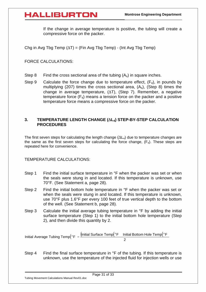
If the change in average temperature is positive, the tubing will create acompressive force on the packer.
Chg in Avg Tbg Temp (∆T) = (Fin Avg Tbg Temp) - (Int Avg Tbg Temp)
FORCE CALCULATIONS:
Step 8 Find the cross sectional area of the tubing (As) in square inches.
Step 9 Calculate the force change due to temperature effect, (F4), in pounds bymultiplying (207) times the cross sectional area, (As), (Step 8) times thechange in average temperature, (∆T), (Step 7). Remember, a negativetemperature force (F4) means a tension force on the packer and a positivetemperature force means a compressive force on the packer.
3. TEMPERATURE LENGTH CHANGE (∆∆L4) STEP-BY-STEP CALCULATIONPROCEDURES
The first seven steps for calculating the length change (∆L4) due to temperature changes arethe same as the first seven steps for calculating the force change, (F4). These steps arerepeated here for convenience.
TEMPERATURE CALCULATIONS:
Step 1 Find the initial surface temperature in °F when the packer was set or whenthe seals were stung in and located. If this temperature is unknown, use70°F. (See Statement a, page 28).
Step 2 Find the initial bottom hole temperature in °F when the packer was set orwhen the seals were stung in and located. If this temperature is unknown,use 70°F plus 1.6°F per every 100 feet of true vertical depth to the bottomof the well. (See Statement b, page 28).
Step 3 Calculate the initial average tubing temperature in °F by adding the initialsurface temperature (Step 1) to the initial bottom hole temperature (Step2), and then divide this quantity by 2.
( ) ( ) ( )( )2
FTempHoleBottomInitialFTempSurfaceInitialFTempTubingAverageInitial
ooo +
=
Step 4 Find the final surface temperature in °F of the tubing. If this temperature isunknown, use the temperature of the injected fluid for injection wells or use
Page 32 of 33Tubing Movement Calculations Manual Rev01.doc
Montrose Engineering Department
the initial bottom hole temperature for producing wells. (See Statement e,page 151).
Step 5 Find the final bottom hole temperature in °F of the tubing. If thistemperature is unknown, use the temperature of the injected fluid forinjection wells or use the initial bottom hole temperature for productionwells. (See Statement e, Page 151).
Step 6 Calculate the final average tubing temperature in °F by adding the finalsurface temperature (Step 4) to the final bottom hole temperature (Step 5)and then divide this value by 2.
( ) ( ) ( )( )2
FTempHoleBottomFinalFTempSurfaceFinalFTempTubingAverageFinal
ooo +
=
Step 7 Calculate the change in average tubing temperature (∆T), in °F bysubtracting the initial average tubing temperature (Step 3) from the finalaverage tubing temperature (Step 6). If the change in average temperatureis a negative number, the tubing will create a tension force on the packer.If the change in average temperature is positive, the tubing will create acompressive force on the packer.
Chg in Avg Tbg Temp (∆T) = (Fin Avg Tbg Temp) - Int Avg Tbg Temp)
LENGTH CHANGE CALCULATIONS:
Step 8 Calculate the length of the tubing in inches (L).
Step 9 Calculate the length change due to this temperature effect, (∆L4), ininches, by multiplying (.0000069) times the tubing length in inches (Step 8)times the change in average tubing temperature (Step 7). Remember, anegative temperature length change, (∆L4), means the tubing shrinks anda positive temperature length change means the tubing elongates.
4. TEMPERATURE EFFECT FORMULAS:
The preceding step-by-step procedures can be written in the following equation form:
TEMPERATURE FORCE (F4):
F4 = (207) (As) (∆T)
Page 33 of 33Tubing Movement Calculations Manual Rev01.doc
Montrose Engineering Department
Change in the Tubing Length, (∆L4):
(∆L4) =(L) (β) (∆T)
The terms used in the formulas are defined as:
As = Tubing cross sectional area (in2)
F4 = Force change in pounds due to the temperature effect (lbs)
L = Length of the tubing in inches (in)
∆L4 = Length change in inches due to the temperature effect (in)
∆T = Change in the average tubing temperature (°F)
Chg in Avg Tbg Temp (∆T) = [Fin Avg Tbg Temp (°F)] - [Int Avg TbgTemp (°F)]
Where:
( ) ( ) ( )( )2
FTempHoleBottomFinalFTempSurfaceFinalFTempTubingAverageFinal
ooo +
=
( ) ( ) ( )( )2
FTempHoleBottomInitialFTempSurfaceInitialFTempTubingAverageInitial
ooo +
=
β = The coefficient of thermal expansion (in/in/°F)
(For Steel β =0.0000069 in/in/°F)