trunnion mounted ball valvesliterature.puertoricosupplier.com/078/ov78017.pdf · bfe available...
TRANSCRIPT

Trunnion Mounted Ball Valves
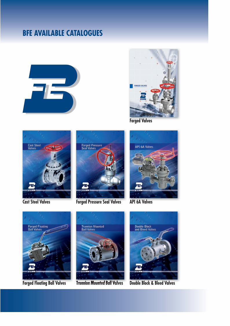
BFE AvAilABlE CAtAloguEs
Forged valves
Cast steel valves Forged Pressure seal valves APi 6A valves
Forged Floating Ball valves trunnion Mounted Ball valvestrunnion Mounted Ball valvesvalvesv Double Block & Bleed valves

Global quality. Total reliability. Two re-
current claims in present-day corporate
strategies. But the transition from words
to actions demands tangible measures.
Specialization and organization underlie
what amounts to a “quality culture” at
BFE, not in the abstract but as a set of
specific rules governing every stage of
production. An operating model that is
good to have in a partner who bears the
responsability of supplying valves that are
essential to plant safety and regulation.

DESIGN, CONSTRUCTION, MARKING FOR TRUNNION BALL VALVESPRODUCT OVERVIEWBFE manufactures the most complete line of quality ball valves, and can provide the exact ball valves and actuators to meet the most demanding application requirements.Our Trunnion Ball Valves are available in an ex-tensive range of designs, materials, sizes and pressure classes and are in full conformance with ANSI, API and NACE specifications.All ball valves are designed in accordance with ASME B16.34 and where applicable with API 6D or BS EN ISO 17292.
The BFE family of trunnion ball valves provides positive shut-off of fluids and gases under ex-treme service conditions.
BFE uses only high-quality materials inspected & tested to International Standards and uti-lizes advanced manufacturing technology with special emphasis on safety, quality, and long service life of our products, to ensure that our clients receive the “best in class” products available from us at a competitive price and delivered on time.
The forging material can ensure the best ri-gidity and strength under maximum rated operation pressure without inherent flaw of cast. Other properties found in forging include greater impact resistance, resistance to fatigue cracking, particularly when cycling at either high or cryogenic temperature.Overdesigned wall thickness and adaptation of high strength tie bolts are convenient for valve maintenance and sufficient to bear the stress of pipe.The internal parts of valve are carefully de-signed and selected to ensure reliability under all kinds of work condition.
Since a variety of materials are available, BFE valves can be used with various fluids and gas-es including petroleum based oils and some water glycols.
Trunnion ball valve have a mechanical means of anchoring the ball at the top and the bot-tom, this design is the standard design applied on larger and higher pressure valves.
Sealing is achieved by spring loaded piston type seats which shut off flow when line pres-sure acts on the upstream seat. Automatic re-lief of cavity overpressure is assured due to the trunnion design in case of self relieving seats (BFE standard design).The ball is operated by a sealed spindle to which the operator is attached.Ball valves are intended to be used as on/off flow control devices and are not to be used to throttle fluid flow. The valves should always be either fully open or closed.
BFE Trunnion Ball Valve design is developed using the latest software based analysis tools.
At the design stage, all projects are analysed using 3D solid modeling tools. Benefits include reduction of development time and cost, im-proved product quality, and ability to solve field problems for customers. Product flexibil-ity and accuracy is assured.
Finite Element Analysis (FEA) is a very impor-tant step at the development stage to ensure the best possible performance requirements. Valves operational problems, pressure/temperature-related deformations and flow-related forces within a valve can be evaluated.
BFE uses the FEA for predicting failure due to unknown stresses by showing problem areas in a material and allowing designers to see all of the theoretical stresses within. This method of product design and testing is far superior to the manufacturing costs which would accrue if each sample was actually built and tested.
During any analysis project, it is the responsi-bility of the BFE analyst to verify that analysis results conform to the physics of the problem under study. Understanding the response of a structure or manufactured product allows effective design decisions to be made in de-veloping structures and products that are func-tional, meet all engineering requirements, and can be manufactured and assembled.Computational Fluid Dynamics (CFD) is used to simulate operating flow conditions.
Evaluation of Valve CV coefficient and convec-tive heat transfer coefficient takes place at the design stage.
MAIN FEATURES
Fire-SaFe TeST approvedBFE trunnion ball valves are designed in ac-cordance with API 607 & API SPEC 6FA. When non-metal seats are destroyed in a fire, the medium pressure push the upstream seat into the ball to cut off the line fluid and prevent internal leakage due to a secondary metal-to-metal seals. When the first soft seal is dam-aged, body/bonnet/stem-gasket can reach sealing function and prevent external fluid leakage.
double body GaSkeTAll BFE trunnion ball valves are equipped with two body gasket. The first body gasket is in soft material and the second in graphite (if not otherwise required), this combination as-sures the best seal characteristic in whatever corrosive service as well give fire safe design.
anTi-STaTic deviceIn order to prevent static electricity which may light the fluid, static-conduction spring is set between the stem/trunnion and the ball.
anTi blow-ouT prooF STemThe stem is designed with integral T-Type shoulder to provide blow-out proof effectively. The design assures that the stem can not be blown out of the valve in the case of the pack-ing being removed while the valve is under pressure.

SELF RELIEVING SEATIn the standard design of TrunnionMounted Ball Valves, each seat ringperforms the “Single Piston” action. Inthis case the pressure acting on theexternal side of the seat ring pushesthe same against the ball while thepressure acting on the internal side ofthe seat rings pushes the same awayfrom the ball. Therefore, while bothseat-rings grant the required tightness,when the pressure is applied on theirexternal side, they are defined “SelfRelieving”, allowing any over pressureacting in the body cavity to be dis-charged in the line as soon as the forcecaused by the pressure overcomes theone provided by the springs.
CONTROLLED STEM & STUFFING BOX FINISHStem and stuffing box finish machining is akey point of control. The stem is made by coldrolling and stem surface finish is controlled byRa=0.4, which can reduce friction for stemmoving and ensure the seal. The stuffing boxsurface is controlled within Ra=1.6 for bettersealing performance.
SOLID BALLThe solid ball used by BFE provides straight-through flow and real full-port performancecharacteristics. Hollow ball or cored cavity ballare not used for BFE products.
BALL SEAT ALIGNMENTStem/Flange mechanical stops ensure controland precise alignment over ball rotation.
LONGEVITY OF LIFESpecial consideration was devoted to theattainment of enhanced life and operation ofour valve throughout design, development,testing and manufacturing stages. Valvedesigns combined with the selection ofadvanced materials are such that long periodsof inactivity should not affect the operationsof efficiency.
LOW TORQUE OUTPUTSeat designs, stem-bearing system and stemseal arrangements ensure consistent minimaltorque values.
FLOW CAPACITYValve design allows for high flow capacity inliquid or gas services regardless of whetherthe media is clean or dirty. Full port valvesallow for pigging and ensure maximum flowcapacity.
FIELD REPARAIBLESimple user friendly design allows for quickand easy part replacement requiring minimal“Down Time”.
ISO FLANGE INTEGRATED IN THE BODYDESIGNISO 5211 mounting always integrated in thevalve as standard design.
EMERGENCY SEALANT INJECTIONFor 6” full port and larger each valve is sup-plied complete with emergency stem sealantinjection feature.
INSPECTION AND TESTINGEvery valve is subjected on routine base to dif-ferent non-destructive testing, like the dyepenetrant test on butt weld ends, on all hardfaced and cladding areas.Non-destructive test are also carried out on thecritical areas as defined by ANSI B.16.34. Optional examinations like:RadiographicMagnetic particiclesUltrasonicHelium leak test Personal performing NDT are trained andqualified to EN 473/ ASNT-SNT-TC-1A.Every valve is subject to a pressure test inaccordance with the standard API 598 or BS6755 Part.1.The rated pressure for the applicable pressureclass is in accordance with ANSI B.16.34 / EN12516-1-2.
MARKING AND IDENTIFICATION Each valve is identified on proper name plateand on valve body as required by MSS- SP 25,B 16.34 Name plate carries all information onrating, size, valve body and trim material, cus-tomer tags. On body, marking includes materi-al designations (per ASTM) and heat code andof course the trade mark.
PISTON EFFECT PRINCIPLE
DOUBLE PISTON EFFECT OPTIONOn request the seat rings design maybe modified to perform the “DoublePiston Effect” action. In this case thepressure acting on both the externaland internal side of the seat rings,results in a force pushing the sameagainst the ball, therefore each seatring grants the required tightness evenif the pressure is applied in the bodycavity. This features assures dead-tight sealingsimultaneously on both sides of theball and in order to release the possibleover pressure developed into the bodycavity it is necessary to use an externalsafety relief valve.
LOW PRESSURE
HIGH PRESSURE
LOW PRESSURE
HIGH PRESSURE
LOW PRESSURE
HIGH PRESSURE
LOW PRESSURE
HIGH PRESSURE
Cat_TRUNNION_MOUNTED_2010_04:Cat_TRUNNION_MOUNTED_2010 1-04-2010 15:47 Pagina 5

TRUNNION MOUNTED BALL VALVES - ASME CLASS 150
SIZE Inch A1 A2 A3 B H Weight Kg Figure N°1/2” 108,5 – 165 13 55 6,5 1-8033/4” 117,5 – 191 19 57 8 1-8041” 127 140 216 25 70 9,5 1-805
1-1/4” – – – – – – 1-8061-1/2” 165 178 191 38 90 19 1-807
2” 178 191 216 50 98 25 1-8083” 203 216 283 75 154 52 1-8104” 229 241 305 101 188 88 1-8116” 394 406 457 151 250 180 1-8138” 457 470 521 202 280 260 1-814
10” 533 546 559 253 315 400 1-81512” 610 622 635 304 340 570 1-81614” 686 699 762 335 380 790 1-81716” 762 775 838 386 420 1040 1-81818” 864 876 914 437 445 1220 1-81920” 914 927 991 488 500 1800 1-82022” 991 1003 1092 539 530 2350 1-82224” 1067 1080 1143 590 590 3200 1-824
SIDE ENTRY - FULL BORE TOP ENTRY - FULL BORE
A1 (RAISED FACE)
H
ØB
A2 (RING JOINT)A3 (BUTT WELD)
ØB
H
A1 (RAISED FACE)A2 (RING JOINT)A3 (BUTT WELD)
ØB1
ØB
H
A1 (RAISED FACE)
A2 (RING JOINT)
A3 (BUTT WELD)
ØB1
ØB
H
A1 (RAISED FACE)A2 (RING JOINT)A3 (BUTT WELD)
SIZE Inch A1 A2 A3 B B1 H Weight Kg Figure N°3/4”x1/2” 117,5 – 191 13 19 55 7 L1-8041”x3/4” 127 140 216 19 25 57 8,5 L1-805
1-1/4”x1” 140 153 229 25 32 70 10,5 L1-8061-1/2”x1” 165 178 191 25 38 70 12 L1-8072”x1-1/2” 178 191 216 38 50 90 22 L1-808
3”x2” 203 216 283 50 75 98 32 L1-8104”x3” 229 241 305 75 101 154 59 L1-8116”x4” 394 406 457 101 151 188 100 L1-8138”x6” 457 470 521 151 202 250 190 L1-81410”x8” 533 546 559 202 253 280 310 L1-81512”x10” 610 622 635 253 304 315 465 L1-81614”x10” 686 699 762 253 335 315 520 LL1-81714”x12” 686 699 762 304 335 340 620 L1-81716”x12” 762 775 838 304 386 340 720 LL1-81816”x14” 762 775 838 335 386 380 830 L1-81818”x16” 864 876 914 386 437 420 1100 L1-81920”x16” 914 927 991 386 488 420 1250 LL1-82020”x18” 914 927 991 437 488 445 1350 L1-82024”x20” 1067 1080 1143 488 590 500 2000 L1-82428”x24” 1245 – 1346 590 685 590 3200 L1-82830”x24” 1295 – 1397 590 736 590 3450 L1-830
SIDE ENTRY - REDUCED BORESIZE Inch A1 A2 A3 B B1 H Weight Kg Figure N°
3/4”x1/2” 191 – 191 13 19 105 13 L1-B041”x3/4” 216 216 216 19 25 130 16 L1-B05
1-1/4”x1” 229 229 229 25 32 150 19 L1-B061-1/2”x1” 241 241 241 25 38 150 22 L1-B072”x1-1/2” 292 295 292 38 50 200 27 L1-B08
3”x2” 356 359 356 50 75 215 34 L1-B104”x3” 432 435 432 75 101 230 70 L1-B116”x4” 559 562 559 101 151 280 120 L1-B138”x6” 660 664 660 151 202 310 230 L1-B1410”x8” 787 791 787 202 253 330 425 L1-B1512”x10” 838 841 838 253 304 360 500 L1-B1614”x10” 889 892 889 253 335 360 680 LL1-B1714”x12” 889 892 889 304 335 480 800 L1-B1716”x12” 991 994 991 304 386 480 950 LL1-B1816”x14” 991 994 991 335 386 485 920 L1-B1818”x16” 1092 1095 1092 386 437 500 1260 L1-B1920”x16” 1194 1200 1194 386 488 500 1550 LL1-B2020”x18” 1194 1200 1194 437 488 520 1750 L1-B2024”x20” 1397 1407 1397 488 590 570 2400 L1-B2428”x24” 1549 1562 1549 590 685 630 3800 L1-B2830”x24” 1651 1664 1651 590 736 630 4100 L1-B30
TOP ENTRY - REDUCED BORE
SIZE Inch A1 A2 A3 B H Weight Kg Figure N°1/2” 165 – 165 13 105 12 1-B033/4” 191 – 191 19 130 15 1-B041” 216 216 216 25 150 18 1-B05
1-1/4” – – – – – – 1-B061-1/2” 241 241 241 38 200 25 1-B07
2” 292 295 292 50 215 30 1-B083” 356 359 356 75 230 60 1-B104” 432 435 432 101 280 110 1-B116” 559 562 559 151 310 220 1-B138” 660 664 660 202 330 410 1-B14
10” 787 791 787 253 360 580 1-B1512” 838 841 838 304 480 720 1-B1614” 889 892 889 335 485 780 1-B1716” 991 994 991 386 500 1100 1-B1818” 1092 1095 1092 437 520 1550 1-B1920” 1194 1200 1194 488 570 1940 1-B2022” 1295 1305 1295 539 590 2800 1-B2224” 1397 1407 1397 590 630 3200 1-B24
All w
eight
value
s are
relev
ant f
or fla
nged
end v
alves
and c
an be
chan
ged w
ithou
t noti
ce. F
ace t
o fac
e dim
ensio
ns no
t list
ed in
indu
stry s
tanda
rds ar
e sub
ject t
o cha
nge w
ithou
t noti
ce.
Cat_TRUNNION_MOUNTED_2010_04:Cat_TRUNNION_MOUNTED_2010 1-04-2010 15:47 Pagina 6

TRUNNION MOUNTED BALL VALVES - ASME CLASS 300
SIZE Inch A1 A2 A3 B H Weight Kg Figure N°1/2” 140 151 165 13 55 8 3-8033/4” 152 165 191 19 57 9 3-8041” 165 178 216 25 70 11 3-805
1-1/4” – – – – – – 3-8061-1/2” 191 203 191 38 90 23 3-807
2” 216 232 216 50 98 29 3-8083” 283 298 283 75 157 56 3-8104” 305 321 305 101 197 95 3-8116” 403 419 403 151 250 190 3-8138” 502 518 521 202 280 285 3-814
10” 568 584 559 253 330 510 3-81512” 648 664 635 304 360 750 3-81614” 762 778 762 335 400 1050 3-81716” 838 854 838 386 430 1450 3-81818” 914 930 914 437 460 1600 3-81920” 991 1010 991 488 510 2200 3-82022” 1092 1114 1092 539 530 2850 3-82224” 1143 1165 1143 590 590 3600 3-824
SIDE ENTRY - FULL BORE TOP ENTRY - FULL BORE
A1 (RAISED FACE)
H
ØB
A2 (RING JOINT)A3 (BUTT WELD)
ØB
H
A1 (RAISED FACE)A2 (RING JOINT)A3 (BUTT WELD)
ØB1
ØB
H
A1 (RAISED FACE)
A2 (RING JOINT)
A3 (BUTT WELD)
ØB1
ØB
H
A1 (RAISED FACE)A2 (RING JOINT)A3 (BUTT WELD)
SIZE Inch A1 A2 A3 B B1 H Weight Kg Figure N°3/4”x1/2” 152 165 191 13 19 55 8,5 L3-8041”x3/4” 165 178 216 19 25 57 9,5 L3-805
1-1/4”x1” 178 191 229 25 32 70 12 L3-8061-1/2”x1” 191 203 191 25 38 70 14 L3-8072”x1-1/2” 216 232 216 38 50 90 26 L3-808
3”x2” 283 298 283 50 75 98 38 L3-8104”x3” 305 321 305 75 101 157 64 L3-8116”x4” 403 419 403 101 151 197 120 L3-8138”x6” 502 518 521 151 202 250 220 L3-814
10”x8” 568 584 559 202 253 280 310 L3-81512”x10” 648 664 635 253 304 330 590 L3-81614”x10” 762 778 762 253 335 330 650 LL3-81714”x12” 762 778 762 304 335 360 820 L3-81716”x12” 838 854 838 304 386 360 970 LL3-81816”x14” 838 854 838 335 386 400 1180 L3-81818”x16” 914 930 914 386 437 430 1600 L3-81920”x16” 991 1010 991 386 488 430 1680 LL3-82020”x18” 991 1010 991 437 488 460 1800 L3-82024”x20” 1143 1165 1143 488 590 510 2700 L3-82428”x24” 1346 1372 1346 590 685 590 4300 L3-82830”x24” 1397 1422 1397 590 736 590 4600 L3-830
SIDE ENTRY - REDUCED BORESIZE Inch A1 A2 A3 B B1 H Weight Kg Figure N°
3/4”x1/2” 191 191 191 13 19 105 15 L3-B041”x3/4” 216 216 216 19 25 130 18 L3-B05
1-1/4”x1” 229 229 229 25 32 150 22 L3-B061-1/2”x1” 241 241 241 25 38 150 25 L3-B072”x1-1/2” 292 295 292 38 50 200 30 L3-B08
3”x2” 356 359 356 50 75 215 40 L3-B104”x3” 432 435 432 75 101 230 80 L3-B116”x4” 559 562 559 101 151 280 160 L3-B138”x6” 660 664 660 151 202 310 280 L3-B1410”x8” 787 791 787 202 253 330 540 L3-B15
12”x10” 838 841 838 253 304 360 580 L3-B1614”x10” 889 892 889 253 335 360 790 LL3-B1714”x12” 889 892 889 304 335 480 920 L3-B1716”x12” 991 994 991 304 386 480 1100 LL3-B1816”x14” 991 994 991 335 386 485 1200 L3-B1818”x16” 1092 1095 1092 386 437 500 1500 L3-B1920”x16” 1194 1200 1194 386 488 500 1800 LL3-B2020”x18” 1194 1200 1194 437 488 520 2100 L3-B2024”x20” 1397 1407 1397 488 590 570 2800 L3-B2428”x24” 1549 1562 1549 590 685 630 4500 L3-B2830”x24” 1651 1664 1651 590 736 630 4800 L3-B30
TOP ENTRY - REDUCED BORE
SIZE Inch A1 A2 A3 B H Weight Kg Figure N°1/2” 165 163 165 13 105 15 3-B033/4” 191 191 191 19 130 18 3-B041” 216 216 216 25 150 21 3-B05
1-1/4” – – – – – – 3-B061-1/2” 241 241 241 38 200 28 3-B07
2” 292 295 292 50 215 38 3-B083” 356 359 356 75 230 66 3-B104” 432 435 432 101 280 120 3-B116” 559 562 559 151 310 230 3-B138” 660 664 660 202 330 430 3-B1410” 787 791 787 253 360 620 3-B1512” 838 841 838 304 480 730 3-B1614” 889 892 889 335 485 790 3-B1716” 991 994 991 386 500 1130 3-B1818” 1092 1095 1092 437 520 1580 3-B1920” 1194 1200 1194 488 570 1980 3-B2022” 1295 1305 1295 539 590 2860 3-B2224” 1397 1407 1397 590 630 3260 3-B24
All w
eight
value
s are
relev
ant f
or fla
nged
end v
alves
and c
an be
chan
ged w
ithou
t noti
ce. F
ace t
o fac
e dim
ensio
ns no
t list
ed in
indu
stry s
tanda
rds ar
e sub
ject t
o cha
nge w
ithou
t noti
ce.
Cat_TRUNNION_MOUNTED_2010_04:Cat_TRUNNION_MOUNTED_2010 1-04-2010 15:47 Pagina 7
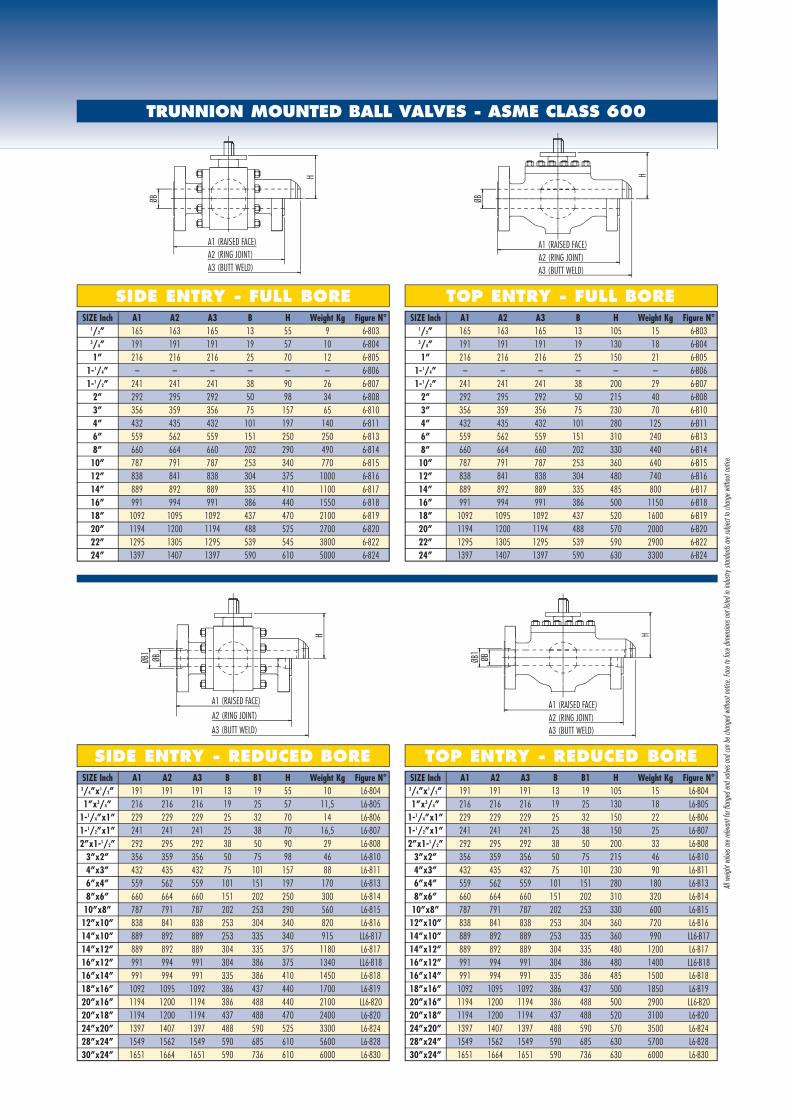
TRUNNION MOUNTED BALL VALVES - ASME CLASS 600
SIZE Inch A1 A2 A3 B H Weight Kg Figure N°1/2” 165 163 165 13 55 9 6-8033/4” 191 191 191 19 57 10 6-8041” 216 216 216 25 70 12 6-805
1-1/4” – – – – – – 6-8061-1/2” 241 241 241 38 90 26 6-807
2” 292 295 292 50 98 34 6-8083” 356 359 356 75 157 65 6-8104” 432 435 432 101 197 140 6-8116” 559 562 559 151 250 250 6-8138” 660 664 660 202 290 490 6-814
10” 787 791 787 253 340 770 6-81512” 838 841 838 304 375 1000 6-81614” 889 892 889 335 410 1100 6-81716” 991 994 991 386 440 1550 6-81818” 1092 1095 1092 437 470 2100 6-81920” 1194 1200 1194 488 525 2700 6-82022” 1295 1305 1295 539 545 3800 6-82224” 1397 1407 1397 590 610 5000 6-824
SIDE ENTRY - FULL BORE TOP ENTRY - FULL BORE
A1 (RAISED FACE)
H
ØB
A2 (RING JOINT)A3 (BUTT WELD)
ØB
H
A1 (RAISED FACE)A2 (RING JOINT)A3 (BUTT WELD)
ØB1
ØB
H
A1 (RAISED FACE)
A2 (RING JOINT)
A3 (BUTT WELD)
ØB1
ØB
H
A1 (RAISED FACE)A2 (RING JOINT)A3 (BUTT WELD)
SIZE Inch A1 A2 A3 B B1 H Weight Kg Figure N°3/4”x1/2” 191 191 191 13 19 55 10 L6-8041”x3/4” 216 216 216 19 25 57 11,5 L6-805
1-1/4”x1” 229 229 229 25 32 70 14 L6-8061-1/2”x1” 241 241 241 25 38 70 16,5 L6-8072”x1-1/2” 292 295 292 38 50 90 29 L6-808
3”x2” 356 359 356 50 75 98 46 L6-8104”x3” 432 435 432 75 101 157 88 L6-8116”x4” 559 562 559 101 151 197 170 L6-8138”x6” 660 664 660 151 202 250 300 L6-81410”x8” 787 791 787 202 253 290 560 L6-81512”x10” 838 841 838 253 304 340 820 L6-81614”x10” 889 892 889 253 335 340 915 LL6-81714”x12” 889 892 889 304 335 375 1180 L6-81716”x12” 991 994 991 304 386 375 1340 LL6-81816”x14” 991 994 991 335 386 410 1450 L6-81818”x16” 1092 1095 1092 386 437 440 1700 L6-81920”x16” 1194 1200 1194 386 488 440 2100 LL6-82020”x18” 1194 1200 1194 437 488 470 2400 L6-82024”x20” 1397 1407 1397 488 590 525 3300 L6-82428”x24” 1549 1562 1549 590 685 610 5600 L6-82830”x24” 1651 1664 1651 590 736 610 6000 L6-830
SIDE ENTRY - REDUCED BORESIZE Inch A1 A2 A3 B B1 H Weight Kg Figure N°
3/4”x1/2” 191 191 191 13 19 105 15 L6-B041”x3/4” 216 216 216 19 25 130 18 L6-B05
1-1/4”x1” 229 229 229 25 32 150 22 L6-B061-1/2”x1” 241 241 241 25 38 150 25 L6-B072”x1-1/2” 292 295 292 38 50 200 33 L6-B08
3”x2” 356 359 356 50 75 215 46 L6-B104”x3” 432 435 432 75 101 230 90 L6-B116”x4” 559 562 559 101 151 280 180 L6-B138”x6” 660 664 660 151 202 310 320 L6-B1410”x8” 787 791 787 202 253 330 600 L6-B1512”x10” 838 841 838 253 304 360 720 L6-B1614”x10” 889 892 889 253 335 360 990 LL6-B1714”x12” 889 892 889 304 335 480 1200 L6-B1716”x12” 991 994 991 304 386 480 1400 LL6-B1816”x14” 991 994 991 335 386 485 1500 L6-B1818”x16” 1092 1095 1092 386 437 500 1850 L6-B1920”x16” 1194 1200 1194 386 488 500 2900 LL6-B2020”x18” 1194 1200 1194 437 488 520 3100 L6-B2024”x20” 1397 1407 1397 488 590 570 3500 L6-B2428”x24” 1549 1562 1549 590 685 630 5700 L6-B2830”x24” 1651 1664 1651 590 736 630 6000 L6-B30
TOP ENTRY - REDUCED BORE
SIZE Inch A1 A2 A3 B H Weight Kg Figure N°1/2” 165 163 165 13 105 15 6-B033/4” 191 191 191 19 130 18 6-B041” 216 216 216 25 150 21 6-B05
1-1/4” – – – – – – 6-B061-1/2” 241 241 241 38 200 29 6-B07
2” 292 295 292 50 215 40 6-B083” 356 359 356 75 230 70 6-B104” 432 435 432 101 280 125 6-B116” 559 562 559 151 310 240 6-B138” 660 664 660 202 330 440 6-B14
10” 787 791 787 253 360 640 6-B1512” 838 841 838 304 480 740 6-B1614” 889 892 889 335 485 800 6-B1716” 991 994 991 386 500 1150 6-B1818” 1092 1095 1092 437 520 1600 6-B1920” 1194 1200 1194 488 570 2000 6-B2022” 1295 1305 1295 539 590 2900 6-B2224” 1397 1407 1397 590 630 3300 6-B24
All w
eight
value
s are
relev
ant f
or fla
nged
end v
alves
and c
an be
chan
ged w
ithou
t noti
ce. F
ace t
o fac
e dim
ensio
ns no
t list
ed in
indu
stry s
tanda
rds ar
e sub
ject t
o cha
nge w
ithou
t noti
ce.
Cat_TRUNNION_MOUNTED_2010_04:Cat_TRUNNION_MOUNTED_2010 1-04-2010 15:47 Pagina 8
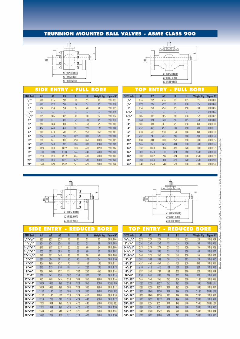
TRUNNION MOUNTED BALL VALVES - ASME CLASS 900
SIZE Inch A1 A2 A3 B H Weight Kg Figure N°1/2” 216 216 216 13 55 13 90H 8033/4” 229 229 229 19 57 15 90H 8041” 254 254 254 25 70 20 90H 805
1-1/4” – – – – – – 90H 8061-1/2” 305 305 305 38 90 34 90H 807
2” 368 371 368 50 103 49 90H 8083” 381 384 381 75 163 79 90H 8104” 457 460 457 101 220 190 90H 8116” 610 613 610 151 260 350 90H 8138” 737 740 737 202 300 590 90H 814
10” 838 841 838 253 350 1000 90H 81512” 965 968 965 304 380 1500 90H 81614” 1029 1038 1029 323 410 1650 90H 81716” 1130 1140 1130 374 440 2200 90H 81818” 1219 1232 1219 424 480 2900 90H 81920” 1321 1334 1321 472 530 4300 90H 82024” 1549 1568 1549 571 620 6900 90H 824
SIDE ENTRY - FULL BORE TOP ENTRY - FULL BORE
A1 (RAISED FACE)
H
ØB
A2 (RING JOINT)A3 (BUTT WELD)
ØB
H
A1 (RAISED FACE)A2 (RING JOINT)A3 (BUTT WELD)
ØB1
ØB
H
A1 (RAISED FACE)
A2 (RING JOINT)
A3 (BUTT WELD)
ØB1
ØB
H
A1 (RAISED FACE)A2 (RING JOINT)A3 (BUTT WELD)
SIZE Inch A1 A2 A3 B B1 H Weight Kg Figure N°3/4”x1/2” 229 229 229 13 19 55 15 90HL 8041”x3/4” 254 254 254 19 25 57 18 90HL 805
1-1/4”x1” 279 279 279 25 32 70 24 90HL 8061-1/2”x1” 305 305 305 25 38 70 29 90HL 8072”x1-1/2” 368 371 368 38 50 90 40 90HL 808
3”x2” 381 384 381 50 75 103 54 90HL 8104”x3” 457 460 457 75 101 163 103 90HL 8116”x4” 610 613 610 101 151 220 230 90HL 8138”x6” 737 740 737 151 202 260 450 90HL 814
10”x8” 838 841 838 202 253 300 700 90HL 81512”x10” 965 968 965 253 304 350 1200 90HL 81614”x10” 1029 1038 1029 253 323 350 1300 90HLL 81714”x12” 1029 1038 1029 304 323 380 1600 90HL 81716”x12” 1130 1140 1130 304 374 380 1700 90HLL 81816”x14” 1130 1140 1130 323 374 410 1800 90HL 81818”x16” 1219 1232 1219 374 424 440 2500 90HL 81920”x16” 1321 1334 1321 374 472 440 2900 90HLL 82020”x18” 1321 1334 1321 424 472 480 3350 90HL 82024”x20” 1549 1568 1549 472 571 530 5700 90HL 82430”x24” 1880 1902 1880 571 713 620 8600 90HL 830
SIDE ENTRY - REDUCED BORESIZE Inch A1 A2 A3 B B1 H Weight Kg Figure N°
3/4”x1/2” 229 229 229 13 19 105 24 90HL B041”x3/4” 254 254 254 19 25 130 30 90HL B05
1-1/4”x1” 279 279 279 25 32 150 35 90HL B061-1/2”x1” 305 305 305 25 38 150 40 90HL B072”x1-1/2” 368 371 368 38 50 200 55 90HL B08
3”x2” 381 384 381 50 75 215 70 90HL B104”x3” 457 460 457 75 101 230 140 90HL B116”x4” 610 613 610 101 151 280 280 90HL B138”x6” 737 740 737 151 202 310 550 90HL B1410”x8” 838 841 838 202 253 340 900 90HL B15
12”x10” 965 968 965 253 304 380 1100 90HL B1614”x10” 1029 1038 1029 253 323 380 1300 90HLL B1714”x12” 1029 1038 1029 304 323 500 1800 90HL B1716”x12” 1130 1140 1130 304 374 500 2100 90HLL B1816”x14” 1130 1140 1130 323 374 520 2200 90HL B1818”x16” 1219 1232 1219 374 424 540 2900 90HL B1920”x16” 1321 1334 1321 374 472 540 3500 90HLL B2020”x18” 1321 1334 1321 424 472 590 3800 90HL B2024”x20” 1549 1568 1549 472 571 620 5400 90HL B2430”x24” 1880 1902 1880 571 713 690 9000 90HL B30
TOP ENTRY - REDUCED BORE
SIZE Inch A1 A2 A3 B H Weight Kg Figure N°1/2” 216 216 216 13 105 21 90H B033/4” 229 229 229 19 130 25 90H B041” 254 254 254 25 150 30 90H B05
1-1/4” – – – – – – 90H B061-1/2” 305 305 305 38 200 52 90H B07
2” 368 371 368 50 215 68 90H B083” 381 384 381 75 230 120 90H B104” 457 460 457 101 280 210 90H B116” 610 613 610 151 310 440 90H B138” 737 740 737 202 340 680 90H B1410” 838 841 838 253 380 1000 90H B1512” 965 968 965 304 500 1400 90H B1614” 1029 1038 1029 323 520 1800 90H B1716” 1130 1140 1130 374 540 2600 90H B1818” 1219 1232 1219 424 590 3500 90H B1920” 1321 1334 1321 472 620 4500 90H B2024” 1549 1568 1549 571 690 7300 90H B24
All w
eight
value
s are
relev
ant f
or fla
nged
end v
alves
and c
an be
chan
ged w
ithou
t noti
ce. F
ace t
o fac
e dim
ensio
ns no
t list
ed in
indu
stry s
tanda
rds ar
e sub
ject t
o cha
nge w
ithou
t noti
ce.
Cat_TRUNNION_MOUNTED_2010_04:Cat_TRUNNION_MOUNTED_2010 1-04-2010 15:48 Pagina 9

TRUNNION MOUNTED BALL VALVES - ASME CLASS 1500
SIZE Inch A1 A2 A3 B H Weight Kg Figure N°1/2” 216 216 216 13 55 13 15H 8033/4” 229 229 229 19 57 15 15H 8041” 254 254 254 25 70 20 15H 805
1-1/4” – – – – – – 15H 8061-1/2” 305 305 305 38 90 34 15H 807
2” 368 371 368 50 103 49 15H 8083” 470 473 470 75 163 100 15H 8104” 546 549 546 101 220 200 15H 8116” 705 711 705 145 270 490 15H 8138” 832 841 832 193 310 830 15H 814
10” 991 1000 991 240 360 1500 15H 81512” 1130 1146 1130 288 420 2300 15H 81614” 1257 1276 1257 316 440 2800 15H 81716” 1384 1407 1384 361 480 4100 15H 81818” 1477 1499 1537 406 560 6400 15H 81920” 1664 1686 1664 456 620 9100 15H 82024” 1782 1810 2043 531 700 15000 15H 824
SIDE ENTRY - FULL BORE TOP ENTRY - FULL BORE
A1 (RAISED FACE)
H
ØB
A2 (RING JOINT)A3 (BUTT WELD)
ØB
H
A1 (RAISED FACE)A2 (RING JOINT)A3 (BUTT WELD)
ØB1
ØB
H
A1 (RAISED FACE)
A2 (RING JOINT)
A3 (BUTT WELD)
ØB1
ØB
H
A1 (RAISED FACE)A2 (RING JOINT)A3 (BUTT WELD)
SIZE Inch A1 A2 A3 B B1 H Weight Kg Figure N°3/4”x1/2” 229 229 229 13 19 55 15 15HL 8041”x3/4” 254 254 254 19 25 57 18 15HL 805
1-1/4”x1” 279 279 279 25 32 70 24 15HL 8061-1/2”x1” 305 305 305 25 38 70 29 15HL 8072”x1-1/2” 368 371 368 38 50 90 40 15HL 808
3”x2” 470 473 470 50 75 103 67 15HL 8104”x3” 546 549 546 75 101 163 124 15HL 8116”x4” 705 711 705 101 145 220 290 15HL 8138”x6” 832 841 832 145 193 270 570 15HL 81410”x8” 991 1000 991 193 240 310 1050 15HL 81512”x10” 1130 1146 1130 240 288 360 1800 15HL 81614”x10” 1257 1276 1257 240 316 360 2150 15HLL 81714”x12” 1257 1276 1257 288 316 420 2500 15HL 81716”x12” 1384 1407 1384 288 361 420 2900 15HLL 81816”x14” 1384 1407 1384 316 361 440 3300 15HL 81818”x16” 1477 1499 1537 361 406 480 5000 15HL 81920”x16” 1664 1686 1664 361 456 480 5200 15HLL 82020”x18” 1664 1686 1664 406 456 560 7600 15HL 82024”x20” 1782 1810 2043 456 531 620 11000 15HL 824
SIDE ENTRY - REDUCED BORESIZE Inch A1 A2 A3 B B1 H Weight Kg Figure N°
3/4”x1/2” 229 229 229 13 19 105 24 15HL B041”x3/4” 254 254 254 19 25 130 30 15HL B05
1-1/4”x1” 279 279 279 25 32 150 35 15HL B061-1/2”x1” 305 305 305 25 38 150 40 15HL B072”x1-1/2” 368 371 368 38 50 200 55 15HL B08
3”x2” 470 473 470 50 75 215 90 15HL B104”x3” 546 549 546 75 101 240 200 15HL B116”x4” 705 711 705 101 145 290 370 15HL B138”x6” 832 841 832 145 193 320 700 15HL B1410”x8” 991 1000 991 193 240 360 1300 15HL B1512”x10” 1130 1146 1130 240 288 400 1580 15HL B1614”x10” 1257 1276 1257 240 316 400 2200 15HLL B1714”x12” 1257 1276 1257 288 316 520 2700 15HL B1716”x12” 1384 1407 1384 288 361 520 3100 15HLL B1816”x14” 1384 1407 1384 316 361 550 3300 15HL B1818”x16” 1477 1499 1537 361 406 570 4300 15HL B1920”x16” 1664 1686 1664 361 456 570 4600 15HLL B2020”x18” 1664 1686 1664 406 456 610 6000 15HL B2024”x20” 1782 1810 2043 456 531 650 9400 15HL B24
TOP ENTRY - REDUCED BORE
SIZE Inch A1 A2 A3 B H Weight Kg Figure N°1/2” 216 216 216 13 105 21 15H B033/4” 229 229 229 19 130 25 15H B041” 254 254 254 25 150 30 15H B05
1-1/4” – – – – – – 15H B061-1/2” 305 305 305 38 200 52 15H B07
2” 368 371 368 50 215 68 15H B083” 470 473 470 75 240 150 15H B104” 546 549 546 101 290 280 15H B116” 705 711 705 145 320 600 15H B138” 832 841 832 193 360 1100 15H B14
10” 991 1000 991 240 400 1450 15H B1512” 1130 1146 1130 288 520 2000 15H B1614” 1257 1276 1257 316 550 2600 15H B1716” 1384 1407 1384 361 570 3900 15H B1818” 1477 1499 1537 406 610 5100 15H B1920” 1664 1686 1664 456 650 6700 15H B2024” 1782 1810 2043 531 710 11800 15H B24
All w
eight
value
s are
relev
ant f
or fla
nged
end v
alves
and c
an be
chan
ged w
ithou
t noti
ce. F
ace t
o fac
e dim
ensio
ns no
t list
ed in
indu
stry s
tanda
rds ar
e sub
ject t
o cha
nge w
ithou
t noti
ce.
Cat_TRUNNION_MOUNTED_2010_04:Cat_TRUNNION_MOUNTED_2010 1-04-2010 15:48 Pagina 10

TRUNNION MOUNTED BALL VALVES - ASME CLASS 2500
SIZE Inch A1 A2 A3 B H Weight Kg Figure N°1/2” 264 264 264 13 55 21 25H 8033/4” 273 273 273 15,5 57 25 25H 8041” 308 308 308 21 70 30 25H 805
1-1/4” – – – – – – 25H 8061-1/2” 384 387 384 32 98 53 25H 807
2” 451 454 451 43 125 89 25H 8083” 578 584 578 63 190 200 25H 8104” 673 683 673 88 240 390 25H 8116” 914 927 914 131 280 780 25H 8138” 1022 1038 1022 179 380 1360 25H 814
10” 1270 1292 1270 223 450 2100 25H 81512” 1422 1445 1422 265 520 3280 25H 816
SIDE ENTRY - FULL BORE TOP ENTRY - FULL BORE
A1 (RAISED FACE)
H
ØB
A2 (RING JOINT)A3 (BUTT WELD)
ØB
H
A1 (RAISED FACE)A2 (RING JOINT)A3 (BUTT WELD)
ØB1
ØB
H
A1 (RAISED FACE)
A2 (RING JOINT)
A3 (BUTT WELD)
ØB1
ØB
H
A1 (RAISED FACE)A2 (RING JOINT)A3 (BUTT WELD)
SIZE Inch A1 A2 A3 B B1 H Weight Kg Figure N°3/4”x1/2” 273 273 273 13 15,5 55 24 25HL 8041”x3/4” 308 308 308 15,5 21 57 28 25HL 805
1-1/4”x1” 349 352 349 21 32 70 35 25HL 8061-1/2”x1” 384 387 384 21 38 70 42 25HL 8072”x1-1/2” 451 454 451 32 43 98 66 25HL 808
3”x2” 578 584 578 43 63 125 152 25HL 8104”x3” 673 683 673 63 88 190 290 25HL 8116”x4” 914 927 914 88 131 240 530 25HL 8138”x6” 1022 1038 1022 131 179 280 1100 25HL 814
10”x8” 1270 1292 1270 179 223 380 1750 25HL 81512”x10” 1422 1445 1422 223 265 450 2600 25HL 816
SIDE ENTRY - REDUCED BORESIZE Inch A1 A2 A3 B B1 H Weight Kg Figure N°
3/4”x1/2” 273 273 273 13 15,5 120 35 25HL B041”x3/4” 308 308 308 15,5 21 150 43 25HL B05
1-1/4”x1” 349 352 349 21 32 180 59 25HL B061-1/2”x1” 384 387 384 21 38 180 69 25HL B072”x1-1/2” 451 454 451 32 43 220 100 25HL B08
3”x2” 578 584 578 43 63 230 160 25HL B104”x3” 673 683 673 63 88 260 300 25HL B116”x4” 914 927 914 88 131 310 680 25HL B138”x6” 1022 1038 1022 131 179 360 1200 25HL B1410”x8” 1270 1292 1270 179 223 440 2200 25HL B15
12”x10” 1422 1445 1422 223 265 490 3400 25HL B16
TOP ENTRY - REDUCED BORE
SIZE Inch A1 A2 A3 B H Weight Kg Figure N°1/2” 264 264 264 13 120 30 25H B033/4” 273 273 273 15,5 150 38 25H B041” 308 308 308 21 180 49 25H B05
1-1/4” – – – – – – 25H B061-1/2” 384 387 384 32 220 78 25H B07
2” 451 454 451 43 230 120 25H B083” 578 584 578 63 260 250 25H B104” 673 683 673 88 310 470 25H B116” 914 927 914 131 360 940 25H B138” 1022 1038 1022 179 440 1400 25H B1410” 1270 1292 1270 223 490 2600 25H B1512” 1422 1445 1422 265 580 4300 25H B16
All w
eight
value
s are
relev
ant f
or fla
nged
end v
alves
and c
an be
chan
ged w
ithou
t noti
ce. F
ace t
o fac
e dim
ensio
ns no
t list
ed in
indu
stry s
tanda
rds ar
e sub
ject t
o cha
nge w
ithou
t noti
ce.
Cat_TRUNNION_MOUNTED_2010_04:Cat_TRUNNION_MOUNTED_2010 1-04-2010 15:48 Pagina 11
020
60
100
140
180
220
260
300
340
380
420
460
500
250 200 150 100 50 – 0 + 50 100 150 200 250 300
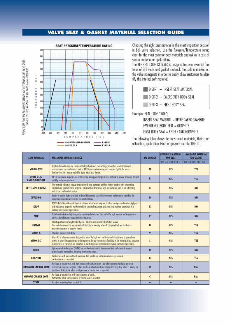
SEAT PRESSURE/TEMPERATURE RATING
R - RPTFE CARBO-GRAPHITE P - PEEKD - DEVLON V K - KEL-F
VALVE SEAT & GASKET MATERIAL SELECTION GUIDE
Choosing the right seat material is the most important decisionin ball valve selection. Use the Pressure/Temperature ratingchart for the most common seat materials and ask us in case ofspecial material or applications.The BFE SEAL CODE (3 digits) is designed to cover essential fea-tures of BFE seats and gasket material, the code is marked onthe valve nameplate in order to easily allow customers to iden-tify the internal soft material.
Example: SEAL CODE “RGR”:INSERT SEAT MATERIAL = RPTFE CARBO-GRAPHITEEMERGENCY BODY SEAL = GRAPHITEFIRST BODY SEAL = RPTFE CARBO-GRAPHITE.
The following table shows the most used materials, their char-acteristics, application (seat or gasket) and the BFE ID.
DIGIT-1 – INSERT SEAT MATERIAL
DIGIT-2 – EMERGENCY BODY SEAL
DIGIT-3 – FIRST BODY SEAL
PLEA
SE N
OTE T
HAT T
HE FO
LLOW
ING
RATIN
GS A
RE R
EFER
RED
TO TH
E VAL
VE S
EATS
. DO
NOT
USE
THIS
RATIN
GS FO
R TH
E VAL
VE C
LASS
SEL
ECTIO
N.
AVAILABLE MATERIAL AVAILABLE MATERIALSEAL MATERIAL MATERIALS CHARACTERISTICS BFE SYMBOL FOR SEAT FOR GASKET
BFE SEAL CODE DIGIT 1 BFE SEAL CODE DIGIT 2/3Polytetrafluoroethylene is a Fluorocarbon-based polymer. This seating material has excellent chemical
VIRGIN PTFE resistance and low coefficient of friction. PTFE is non-contaminating and accepted by FDA for use in M YES YESfood services. Not recommended for liquid alkalis and fluorine.
RPTFE 25% PTFE’s mechanical properties are enhanced by adding percentage of filler material to provide improved strength, R YES YESCARBO-GRAPHITE stability and wear resistance.
This material exhibits a unique combination of heat resistance and low friction together with outstanding RPTFE 60% BRONZE chemical and good electrical properties. No moisture absorption, high arc resistance, and is self lubricating B YES NO
with a low coefficient of friction.
DEVLON-VDevlon-V (special Nylon produced by Devol Engineering Ltd) offers very good performances regarding the
D YES NOmaximum allowable pressure and excellent elasticity.
PCTFE (Polychlorotrifluoroethylene) is a fluorocarbon based polymer. It offers a unique combination of physical KEL-F and mechanical properties non-flammability, chemical resistance, and near zero moisture absorption. It is K YES NO
suitable for cryogenic applications.
PEEKPolyetheretherketone high temperature semi rigid elastomer. Best suited for high pressure and temperature
P YES NOservice. Also offers very good corrosion resistance.
Ultra-High Molecular Weight Polyethylene. Ideal for use in lowlevel radiation service. UHMWP This seat also meets the requirements of the tobacco industry where TFE is prohibited and it offers an U YES YES
excellent resistance to abrasive media.
VITON A Standard material for O-RING V YES YES
Viton GLT is a fluoroelastomer designed to retain the high heat and the chemical resistance of general use VITON GLT grades of Viton fluoroelastomer, while improving the low temperature flexibility of the material. Glass transition L YES YES
temperatures of materials are indicative of low temperature performance in typical elastomer applications
HNBRHydrogenated nitrile rubber (HNBR) has excellent mechanical, thermo-oxidative and chemical resistant
H YES NOproperties and an excellent operating temperature range.
GRAPHITEHard carbon with excellent heat resistance. Not suitable as seat material when presence of
G YES YESoxidized service is expected.
For liquid or gas services with high presence of solids or in any case where extreme hardness and wear TUNGSTEN CARBIDE COAT resistance is required. Tungsten carbide itself is practically inert and extremely strong. Any attack is usually on W YES N.A.
the binder. Not suitable when small presence of caustic soda is expected.
CHROME CARBIDE COATFor liquid or gas services with small presence of solids.
C YES N.A.Not suitable when small presence of caustic soda is expected.
OTHER For other materials please ask to BFE. – – –
Cat_TRUNNION_MOUNTED_2010_04:Cat_TRUNNION_MOUNTED_2010 1-04-2010 15:48 Pagina 12

CRYOGENIC CONFIGURATION
BFE trunnion ball valves designated for use in cryogenic tempera-tures to minus 196°C (320°F) offer superior service life in toughand demanding applications. The design incorporates a vent hole drilled on the upstream side ofthe ball, eliminating the possibility of trapping liquid or gas in thecavity and thereby preventing dangerous overpressure due to ther-mal expansion. The bonnet extension keeps heat transfer down, the packing frostfree and the operational torque low. Selection of materials of construction is optimized for the intendedservice. Extended bonnets are peovided to ensure zero leakage.
BFE metal seated trunnion ball valves are designed for high tem-perature applications and for abrasive services:
• HIGH TEMPERATURE: BFE trunnion ball valves designated forhigh temperature operation offer superior service life for anykind of fluid compatible with graphite. BFE Metal to Metalsealed ball valves employ a special spring loaded seat design,which would absorb the heat expansion of valve components,so that the valve would not get stuck due the high temperature.
• ABRASIVE SERVICE: The valve is highly resistant to erosion,very effective in the handling of fluids containing abrasives andany dirty media and maintenance free. The valve is providedwith Tungsten Carbide coated metal seats to avoid the erosionof soft seats. Soft seat must not be used for abrasive service.
METAL SEATED CONFIGURATION
OTHER SPECIAL SERVICES
SERVICE DESCRIPTION & VALVE FEATURES
OXYGEN GASBFE trunnion ball valves designated for Oxygen Service are prepared and cleaned to standards required for the safe operation of Oxygen Service equipment and product purity. Acetal Resign (Delrin)seats and Nylatron seals must not be used in oxygen service.
VACUUMBFE trunnion ball valves can be used with standard design in "Medium Vacuum" range (up to 0.001 Torr). Specially prepared and tested valves can be used through the "High Vacuum" range. Valveswith reinforced TFE, carbon-graphite or metal seats are not recommended for vaacum service.
CHLORINEBFE trunnion ball valves designated for Chlorine Service are in stainless steel material (Grade 304 or 316) or other alloys such as Monel or Hastelloy C. Reinforced PTFE can be used for the chlorineservice. Due the high coefficient of expansion the ball vent hole is required. They are prepared and cleaned to standards required.
ALIMENTARYThe BFE special "cavity filled" design (standard design for alimentary service valves) offer the best way to mantain the body cavity clean and empty from impurities. BFE trunnion ball valves designat-ed for alimentary files Service are also prepared and cleaned to standards required.
SLURRY & MUDThe BFE special "cavity filled" design (standard design for slurry service valves) offer the best way to mantain the body cavity empty from slurry and safe from phase transition to the solid state(immobilizing the valve).
RUBBER POLYMERSThe BFE special "cavity filled" design (standard design for polymers service valves) offer the best way to mantain the body cavity empty from fluid and safe from possible polymerization in place(immobilizing the valve).
HYDROGEN PEROXIDE Ball Valves are recommended for hydrogen peroxide service. The valve is nitrogen leak tested and prepared and cleaned to standards required. The ball vent hole is required.
Cat_TRUNNION_MOUNTED_2010_04:Cat_TRUNNION_MOUNTED_2010 1-04-2010 15:48 Pagina 13
QUOTATION VALIDITYUnless otherwise agreed, quotations are valid for fourweeks from date of issue. The delivery terms are always “ex-works” unless other-wise stated.Prices and sale conditions can be changed without anyprevious notice.
ORDERS ACCEPTANCEOrders are considered accepted at our general sale condi-tions clearly mentioned on order acknowledgment.
GOODS DELIVERYThe Company does not accept any responsability fordelays is delivery which are always intended as indicativeand not binding. Transport risks are at receiver’s chargealso in case of CIF delivery.
GUARANTEEThe Company warrantees all its products, from materialand/or manufacturing defects, to be used as recommend-ed by standards, and in accordance with approved pipingpractice and technique, for a period of one year from ship-ping date, unless otherwise agreed.The Company liability covers eventual “free of charge”replacements for defective parts or products, providing ithas not failed in the observance of above mentioned con-ditions and in use in compliance with standards, and, any-way, after return of defective goods. Any other liability,neither objective nor subjective will be accepted.
CLAIMS AND ORDER CANCELLATIONSClaims will be considered only if made within 10 daysfrom goods receipt.Partial or complete cancellations of order can be acceptedonly upon previous agreement or by written consent and,however, not later than 15 days from order date. Any controversy will be handled by the Court of Milan.
GENERAL SALE CONDITIONS
Cat_TRUNNION_MOUNTED_2010_04:Cat_TRUNNION_MOUNTED_2010 1-04-2010 15:48 Pagina 14

Dimensions on the catalogue are indicative.BFE S.r.l. reserves the right to make all necessary changes without notice.
Cat_TRUNNION_MOUNTED_2010_04:Cat_TRUNNION_MOUNTED_2010 1-04-2010 15:48 Pagina 15

B.F.E. S.r.l. - Via Tonale, 70/A - 24061 Albano S.Alessandro (BG) Italy - Phone: 035.584111 - Fax: 035.583022 - Mail: [email protected]
www.bfe.it
+001.814.542.2545www.bonneyforge.com
www.rpc-valve.com+001.713.695.3633 - +001.713.695.3528 fwww.wfi-intl.com