trouble shooting tips for service station maintenance · trouble shooting tips page 4 description:...
TRANSCRIPT
National Parts Distributing Ltdpresents
trouble shooting tips
for Service Station Maintenance
Index
TST 1 Gilbarco Pump Error Codes Page 1 to 12TST 2 Fluorescent’s and You! Page 13 to 14TST 3 Re-Occurring problems on Gilbarco Modular Pumps Page 15TST 4 The Hot Black Head Page 16TST 5 The Noisy Pump That Does Not Pump Page 17 to 23TST 6 Gilbarco Pump/Dispenser Resets Page 24TST 7 T16226-G Main Display Jumper Settings Page 25TST 8 That darn Gilbarco Code 34 Page 26 to 27
code 31 or 35" Page 28TST 10 Turn off that Power! Page 29TST 11 Kraus Type A and B Skil 184 Software Swapping Page 30TST 12 Dead Batteries on Gilbarco TCR-G2 Memory Expansion Boards Page 31TST 13 Kraus Micon 200 Boards Modified for Back Light Page 32TST 14 Those Bugs Bite Page 33TST 15 Sealing D&H Pulsers to Prevent Water Wicking up Shaft Page 34TST 16 Installing DG8340 Esco Printers with Gilbarco Transac Consoles Page 35 to 36TST 17 Esco Genesis and D&H EQ30 Heads Pulse Rates Page 37TST 18 C2000-K Consoles with Kraus Micon & MTI (D&H ) EQ30 - issues Page 38 to 39TST 19 SKIL 409A3 Kraus I.S. Switch Assembly Page 40TST 20 Totalizer Readings from Kraus Micon 100, 200 and 500 and MTI
(D&H) EQ30 Retrofit Heads and Progressive International C2000-K Page 41TST 21 Installing Progressive International C2000 Consoles Page 42
trouble shooting tips
Page 1
No. 1 Gilbarco Pump Error Codes
This first of our "trouble shooting tips" was originally published in 1988 and since that time we havediscovered some errors that we made, plus we have learned of some new codes which have been addedsince that time, therefore we are now updating and reissuing the "tip".
It should be noted to avoid any confusion this bulletin is a summary of all the various codes that weat ERI are aware of, and are our interpretation of those codes.
While we are going to summarize the Codes in this bulletin along with the causes of the Errors, wewill be dealing with some of these in greater detail in future "trouble shooting tips".
There are three basic generations of logic development in Gilbarco pumps and we will detail eachgeneration in succession in this "tips".
IT SHOULD BE NOTED THAT THESE ERROR CODES SHOW UP ON THE PRICE PER UNITDISPLAY OF THE PUMP ITSELF! They do not show up on the Console except for the Transac 12G.
IT SHOULD ALSO BE NOTED THAT THE "ERROR CODE" WILL BE FLASHING BACK ANDFORTH WITH THE PRICE SET ON THE PUMP.
All of the "Error Codes" will stop the pump from operating and some will result in loss ofcommunication with the older Consoles. i.e. When the operator selects the pump on the Consoleit will not be there!
IMPORTANT!!!!!! - TURN OFF POWER TO THE PUMP (AFTER ISOLATINGIT ON SELF SERVE SYSTEMS) BEFORE CHANGING ANY COMPONENTS INTHE PUMP You should carry out trouble shooting in the order that we detail it, from "over the phone to highestnumber. In other words easiest and most likely to most difficult & least likely.
FIRST GENERATION: 8080 LOGIC BUILT FROM DAY 1 TO FALL OF 1985 IN HIGHLINE 111B AND TO FALL OF 1987 IN MULTI PRODUCT. (DOES NOTAPPEAR IN SALESMAKER 4) IN ALL RETROPAC COMPUTERS.
This generation only had two (2) "error codes".
1. FLASHING "PRICE" THEN "BLANK" (DISPLAY GOES OUT) THEN THE "PRICE" AGAIN,AND SO ON.
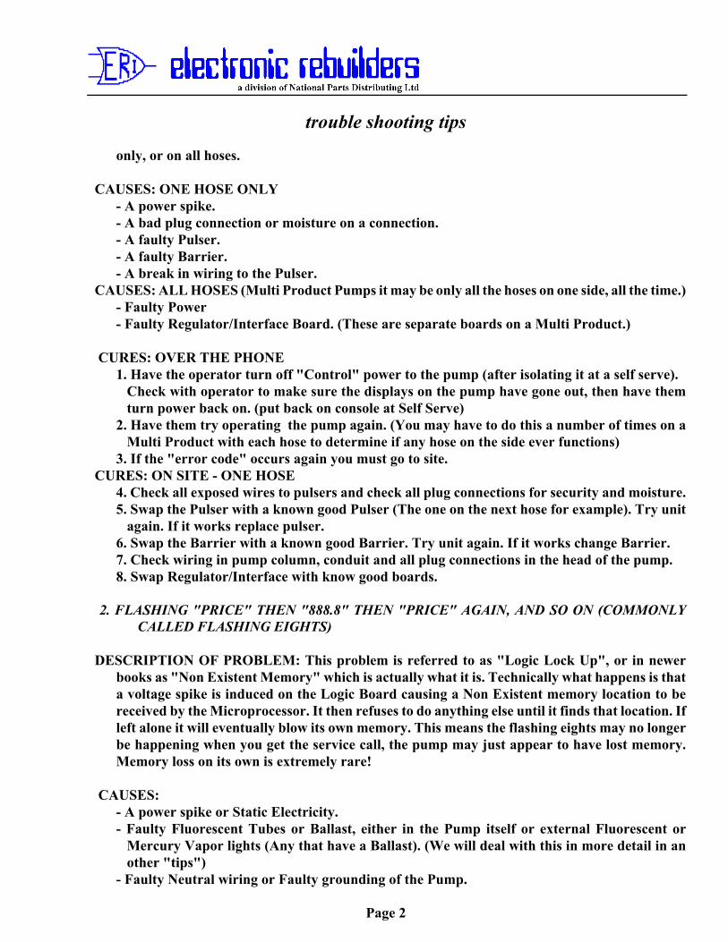
DESCRIPTION OF PROBLEM: A Pulsing System failure. It can happen on only one hose or onall hoses on a pump. It is important to find out "over the phone" if it is occurring on one hose
trouble shooting tips
Page 2
only, or on all hoses.
CAUSES: ONE HOSE ONLY - A power spike. - A bad plug connection or moisture on a connection. - A faulty Pulser. - A faulty Barrier. - A break in wiring to the Pulser.CAUSES: ALL HOSES (Multi Product Pumps it may be only all the hoses on one side, all the time.) - Faulty Power - Faulty Regulator/Interface Board. (These are separate boards on a Multi Product.) CURES: OVER THE PHONE
1. Have the operator turn off "Control" power to the pump (after isolating it at a self serve).Check with operator to make sure the displays on the pump have gone out, then have themturn power back on. (put back on console at Self Serve)
2. Have them try operating the pump again. (You may have to do this a number of times on aMulti Product with each hose to determine if any hose on the side ever functions)
3. If the "error code" occurs again you must go to site.CURES: ON SITE - ONE HOSE
4. Check all exposed wires to pulsers and check all plug connections for security and moisture.5. Swap the Pulser with a known good Pulser (The one on the next hose for example). Try unit
again. If it works replace pulser.6. Swap the Barrier with a known good Barrier. Try unit again. If it works change Barrier.7. Check wiring in pump column, conduit and all plug connections in the head of the pump.8. Swap Regulator/Interface with know good boards.
2. FLASHING "PRICE" THEN "888.8" THEN "PRICE" AGAIN, AND SO ON (COMMONLYCALLED FLASHING EIGHTS)
DESCRIPTION OF PROBLEM: This problem is referred to as "Logic Lock Up", or in newerbooks as "Non Existent Memory" which is actually what it is. Technically what happens is thata voltage spike is induced on the Logic Board causing a Non Existent memory location to bereceived by the Microprocessor. It then refuses to do anything else until it finds that location. Ifleft alone it will eventually blow its own memory. This means the flashing eights may no longerbe happening when you get the service call, the pump may just appear to have lost memory.Memory loss on its own is extremely rare!
CAUSES: - A power spike or Static Electricity.- Faulty Fluorescent Tubes or Ballast, either in the Pump itself or external Fluorescent or
Mercury Vapor lights (Any that have a Ballast). (We will deal with this in more detail in another "tips")
- Faulty Neutral wiring or Faulty grounding of the Pump.
trouble shooting tips
Page 3
- Faulty Logic Board (extremely unlikely, if it is the fault it is usually locked up to the pointwhere it will not do anything including flash eights, reset, or allow you to blow its memory.Occurs, in our experience, less than 1 in 500 occurrences of Logic Lock Up.)
CURES: OVER THE PHONE1. Have the operator turn off "Control" power to the pump (after isolating it at a self serve).
Check with the operator to make sure the displays on the pump have gone out, then have themturn power back on. (put back on Console at Self Serves) The pump should now operate untilwhatever caused the Logic Lock up causes it again. (Remember if the pump lost memory andhas no price on it, it will not run until the operator sets the price again.)
2. Have the operator check the fluorescent in the pump for flickering, darkened ends or totallyout. If any are noted you will have to go the site to change them. Make sure you use properTubes with grounds strips on them. If the problem was a Voltage Spike it may never occuragain (however a Voltage Spike usually locks all of the pumps up at the site and you usuallyrecognize it from this, they also lock up the Consoles easier).
CURES: ON SITE3. If after some time the "Lock Up" occurs again you must take some action. Change the
Fluorescent Tubes in the pump first (even if they do not look bad). Let them run the pumpsagain, if the "lock up" does not occur again in roughly the same time as from their first callto the second call you have probably cured the problem.
4. If it occurs again check out all wiring to the pump. Pay particular attention to Neutral andGrounding.
5. If wiring checks O.K., then change the Ballast and also be suspicious of other lighting near thePump. Have repaired any that looks suspicious. Have them run pumps again.
6. If problem occurs again, change Regulator Board. Have them run pumps again.7. If problem occurs again, Change Logic Board.
SECOND GENERATION: Z80 LOGIC HIGHLINE 111B PUMPS FROM FALL OF 1985 ANDALL SALESMAKER 4 PUMPS TO THE FALL OF 1987. (NO MULTI PRODUCT).
1. FLASHING "PRICE" THEN "002.0" THEN "PRICE", AND SO ON (COMMONLY CALLEDFLASHING 20)
This is the same problem as Problem 1. in the First Generation, a Pulsing System Failure.Description, Causes and Cures are exactly the same, so refer back to it.
2. FLASHING "PRICE" THEN "002.1" THEN "PRICE", AND SO ON. (COMMONLY CALLEDFLASHING 21)
This is the same problem as Problem 2. in the First Generation, a "Logic Lock Up". Description,Causes and Cures are exactly the same, so refer back to it.
3. FLASHING "PRICE" THEN "002.2" THEN "PRICE", AND SO ON.
trouble shooting tips
Page 4
DESCRIPTION: This is a Volume/Money buffer failure. In other words the Microprocessor checksthat the Volume amount times the Price should equal the Money amount but finds it does not,so it shuts the Pump down. (See Servicemen are not the only ones who make mistakes.)
CAUSES: - Power Spike - Static Electricity
- Faulty Logic Board
CURES: OVER THE PHONE1. Have the operator power the pump down and back up as in previous cures. Have them run
the pump again. If the problem does not occur again assume the problem was a power spikeor static and there is nothing wrong with the unit.
CURES: ON SITE2. If it occurs again, check all wiring in the pump for proper Neutral and Grounding. Check the
door to the operator panel on the pump to make sure no part of the door or its lock is touchingthe command module plug, allowing static to the Logic Board.
3. If all this checks O.K., then change the Logic Board.4. FLASHING "PRICE" THEN "002.3" THEN "PRICE, AND SO ON. (COMMONLY CALLED
FLASHING 23)
DESCRIPTION OF PROBLEM: A Grade assignment has changed after the Pump was powered uplast. The operator when calling in will probably complain the Pump has lost memory as theirtotals will have reset to zero. In fact the totals are still there it is just that the pump is nowrunning on the totalizers for another Grade.
CAUSES: - A Jumper failure on the Logic Board.
CURES: ON SITE (NO OVER THE PHONE CURE, DO NOT LET THEM POWER THE UNITDOWN AS IT WILL RUN ON THE WRONG GRADE.)1. Check Jumpers for setting the Grades on the Logic Board and repair as necessary.2. Make sure the Grades are set correctly before powering up the Pump.
5. FLASHING "PRICE" THEN "002.4" THEN "PRICE", AND SO ON. (COMMONLY CALLEDFLASHING 24)
DESCRIPTION OF PROBLEM: The Conversion Factor has changed after Power up. This meansthe pump is no longer calculating in Litres but may be U.S. or Imperial Gallons or somethingtotally different.
CAUSES: - A Jumper failure on the Logic Board.
CURES: ON SITE (NO OVER THE PHONE CURE, DO NOT LET THEM POWER THE PUMPDOWN AS IT WILL PUMP IN WRONG UNIT OF MEASURE WHEN POWERED UP.)
trouble shooting tips
Page 5
1. Check Jumpers for setting the Conversion Factor and repair as necessary.2. Make sure the correct conversion factor is set before powering up the Pump.
6. FLASHING "PRICE" THEN "002.5" THEN "PRICE", AND SO ON. (COMMONLY CALLEDFLASHING 25)
DESCRIPTION OF PROBLEM: The "Two Wire" switch has changed after Power up of the Pump.
CAUSES: - A Customer in an attempt to steal Gas has opened the operator panel door on the PumpThey all have common keys on each model of Pump) and switched the Pump "off Console".(This would only occur at self serves.)- A faulty Two Wire Switch.
CURES: OVER THE PHONE1. Have the Operator open the Operator Panel Door on the Pump and check to make sure switch
is in the correct position ("On Console at a Self Serve). Even if it is the correctposition have them move it to the other position and then back a few times just in case its is dirtin the switch. Then power the pump down and back up again and see if it now functionscorrectly. If it will not operate in self serve but operates on it own you will have to go to site.
CURES: ON SITE2. Check the switch on the Display Board or Display Interface Board, if it is not functioning
change the board.
7. FLASHING "PRICE" THEN "002.6" THEN "PRICE", AND SO ON. (COMMONLY CALLEDFLASHING 27)
DESCRIPTION OF PROBLEM: The Single/Dual Option setting has changed on the pump afterpower up of the Pump. This will usually only occur on a Dual, as youmust set Jumper "on" to make a single pump a dual.
CAUSES: - A Jumper failure on the Logic Board. - Faulty Logic Board.
CURES: ON SITE (NO OVER THE PHONE CURE, POWERING DOWN AND UP WILL ONLYGET ONE SIDE FUNCTIONING.)1. Check the Single/Dual Option Jumper and repair as necessary.2. If unable to repair or no fault found, change the Logic Board.
8. FLASHING "PRICE" THEN "002.7" THEN "PRICE", AND SO ON (COMMONLY CALLEDFLASHING 27)
DESCRIPTION OF PROBLEM: The "A" side Pump I.D. Number has changed after power up ofthe Pump.
trouble shooting tips
Page 6
CAUSES: - The Pump Number setting Jumpers on the Logic Board have failed.- Faulty Logic Board.
CURES: ON SITE (NO OVER THE PHONE CURE, POWERING DOWN AND UP WILL ONLYHAVE IT RUNNING ON THE WRONG PUMP NUMBER, WHICH WILL CONFUSE THECONSOLE.)1. Check the A side pump number Jumpers and repair as necessary.2. If no fault can be found change the Logic Board.
9. FLASHING "PRICE" THEN "002.8" THEN "PRICE", AND SO ON. (COMMONLY CALLEDFLASHING 28)
DESCRIPTION OF PROBLEM: The "B" side Pump I.D. Number has changed after Power up ofthe Pump.
CAUSES: - Same as Flashing 27 above.
CURES: - Same as Flashing 27 above.
10. FLASHING "PRICE" THEN "002.9" THEN "PRICE", AND SO ON. (COMMONLY CALLEDFLASHING 29)
DESCRIPTION OF PROBLEM: Only on Salesmaker 4, it is an invalid Grade assignment orconfiguration change.
CAUSES: - A Jumper failure on Logic Board.- Faulty Logic Board.
CURES: ON SITE (NO OVER THE PHONE CURE)1. Check Jumpers and repair as necessary.2. Change Logic Board.
11. FLASHING "PRICE" THEN "003.0" THEN "PRICE", AND SO ON. (COMMONLY CALLED
FLASHING 30)
DESCRIPTION OF PROBLEM: Only on Highline 111B, is an invalid Grade Assignment orconfiguration change.
CAUSES: same as Flashing 29 above.
CURES: same as Flashing 29 above.
THIRD GENERATION: MODULAR ELECTRONICS ALL UNITS FROM THE FALL OF
trouble shooting tips
Page 7
1987 AND SPRING OF 1988 ON.
FLASHING CODES 20 TO 28 ARE IDENTICAL TO FLASHING CODES 20 TO 28 IN THESECOND GENERATION ABOVE, FOLLOW PROCEDURES FOR THESE.
1. FLASHING "PRICE" THEN "002.9" THEN "PRICE", AND SO ON. (COMMONLY CALLED
FLASHING 29)
DESCRIPTION OF PROBLEM: Pump Time-Out Error.
CAUSES: The unit has been inactive beyond the specified time limit. The transaction is stopped andit will be necessary to turn the pump handle off to clear the error (no power down is needed).Note! this only occurs with software version 50.2 or higher.
CURE OVER THE PHONE: - have the operator turn the pump handle off and back on. (Leave offif the hose is not being used)
CURE ON SITE: - It may be that the site is not supposed to have a "no flow time-out".- In this case the pump configuration has changed and you will have to re configure the pump
to "No pump Time-out" as per Function Code 12 of Command Code 10.
2. FLASHING "PRICE" THEN "003.0" THEN "PRICE", AND SO ON. (COMMONLY CALLEDFLASHING 30)
DESCRIPTION OF PROBLEM: Vapor Sense - unit is programmed for Vapor Sense and switchis not hooked up. (This should only occur with version V53.3 software).
CAUSES: Incorrect programing.
CURES ON SITE: Re program Command Code 10 Function Code 7 to "0" (No vapor sense)
3. FLASHING "PRICE" THEN "003.1" THEN "PRICE", AND SO ON. (COMMONLY CALLEDFLASHING 31)
DESCRIPTION OF PROBLEM: Is a Totals Data Error. It means that the pump totals memory maybe corrupted and should not be trusted.
CAUSES: - Voltage spike.- Static Electricity.- Faulty Controller Board.- Dead Battery (or disconnected Battery) when unit powered down and Microprocessor does
not go through normal shut down.- Disconnecting plugs to boards without first powering the unit down and then turning of the
Battery by pressing "Clear" and then "Enter" on the keypad.
trouble shooting tips
Page 8
CURES: OVER THE PHONE1. Have the Operator Record the Pump Totals.2. Have the Operator perform a Memory Reset as per Command Code 6 on page 19 of their
MDE 2022 User Manual.3. The Totals could be put back in by the Operator on a Multi Product or a Salesmaker 4 by
performing Command Code 7 on page 21 of MDE 2022, however as this will not work on aHighline 111B unless both sides are Grade 1 or the unit is temporarily re configured to anMPD or Salesmaker 4 under Command Code 10 we do not recommend you even attempt tohave the Operator do. Just have them do a shift end and tell them their pump totals for thatpump are reset to zero.
4. Have the Operator set the prices on the pump in their normal fashion.CURES: ON SITE
5. If this code persists in coming up change the Controller Board.
4. FLASHING "PRICE" THEN "003.2" THEN "PRICE", AND SO ON. (COMMONLY CALLEDFLASHING 32)
DESCRIPTION OF PROBLEM: Pulser Count Failure (Do not confuse this with Pulser Failure).The Microprocessor has detected an error between the two pulses coming from the Pulser.
CAUSES: - Voltage Spike. - Defective Pulser.
- Defective Interface Board.- Defective Controller Board.
CURES: OVER THE PHONE1. Have Operator Power the Pump Down and Back up. (No need to isolate with Modular)2. Have them try the Pump again. If it occurs again, go to site.
CURES: ON SITE3. Replace Pulser with known good unit and try the Pump again. If it occurs again go to 4.4. Change Hydraulic Interface Board with known good one and try again.5. Change Controller Board.
5. FLASHING "PRICE" THEN "003.3" THEN "PRICE", AND SO ON. (COMMONLY CALLEDFLASHING 33)
DESCRIPTION OF PROBLEM: - The Heaters for the Displays are on at Power Up.
CAUSES: - The Displays in the Pump where too cold at Power up to Light and the Heaters havebeen turned on.- Defective Heater.- Bad Connection between Power Supply and Display (Trace as per appropriate schematic). - Defective Power Supply - Defective Controller Board.
trouble shooting tips
Page 9
CURES: OVER THE PHONE1. Have the Operator wait until the displays warm up. If this does not occur within one hour of
the Power being applied, go to site.CURES: ON SITE
2. Check for Heater Power at appropriate place on Display Boards (Use appropriate schematicfor type of Pump). If no Heater Power (24 VAC) at display trace back through wiring to findpoint you are loosing it. If no Power from Power Supply, replace it.
3. If there is Heater Power (24 VAC) to the Main Display, replace each Main Display with aknown good one. Close Bezels to allow to warm up. Be aware that Displays that are cold maketake up to an hour to get warm enough to light (at -30 Degrees Celcius this is about a 1/2 hour).If they still do not light after 1 hour go to 4.
4. Replace Controller Board.NOTE! If the Display Power Supply is Defective the the displays will not flash Code 33.
6. FLASHING "PRICE" THEN "003.4" THEN "PRICE", AND SO ON. (COMMONLY CALLEDFLASHING 34)
DESCRIPTION OF PROBLEM: A low Battery condition was detected during automatic Batterytest. (Refer also to our "trouble shooting tip No.8)
CAUSES: - Defective Battery Fuse.- Defective Battery. - Bad Connection between Battery and Regulator Board.- Defective Regulator board.- Software older than version 53.4 on Controller Board.- Defective Controller board.
CURES: OVER THE PHONE1. Have operator perform Command Code 9, Function 1 as detailed on page 24 of MDE2022
User Manual. This will override the Error Code until the next Power Up. If it was just a lowbattery it may not occur again. If it does go to site.
CURES: ON SITE2. Check the Battery Fuse and replace if necessary.3. Replace Battery with known good unit.4. Check wiring between Battery and Regulator Board.5. Replace Regulator Board with known good one.6. Replace Controller Board with known good one.
7. FLASHING "PRICE" THEN "003.5" THEN "PRICE", AND SO ON. (COMMONLY CALLEDFLASHING 35)
DESCRIPTION OF PROBLEM: Configuration data error. The configuration data telling the Pumpwhat it is has changed.
trouble shooting tips
Page 10
CAUSES: - Voltage Spike.- Operator Programming Error (They may have accessed Command Level 2).- Faulty Controller Board.
CURES: ON SITE (NO OVER THE PHONE, MEMORY MUST BE RESET AND THE PUMP RECONFIGURED).1. Record the Pump Totals.2. Perform Command Code 6 as per page 19 of MDE 2022 User Manual.3. Re configure the Pump as per Command Codes 10 through 12 pages 2-1 to 2-17 of MDE2021
Service Manual.4. You may now put the pump totals back in a Multi Product or a Salesmaker 4 by performing
Command Code 7 on page 21 of MDE2022 User Manual, however on a Highline 111B that isnot Grade 1 on both sides you must first temporarily re configure the pump as Salesmaker 4or Multi Product as per Command Code 10, Function Code 1 on page 2-7 of MDE2021 ServiceManual, then enter the totals as per Command Code 7 on page 21 MDE2022 User Manual,then re configure the pump back to be a Highline 111B as per Command Code 10, Function1 page 2-7 MDE2021 Service Manual (as this can be difficult to accomplish properly werecommend having the operator do a shift cut and start the pump totals at zero for this pump).
5. Reset prices as per normal station procedure.
8. FLASHING "PRICE" THEN "003.6" THEN "PRICE, AND SO ON. (COMMONLY CALLEDFLASHING 36)
DESCRIPTION OF PROBLEM: Unit "Type Code" has changed.
CAUSES: Unknown
CURES: ON SITE - Re configure "Unit Type" as per Function 1 of Command Code 10.- If problem repeats, replace Controller board.
9. FLASHING "PRICE" THEN "003.7" THEN "PRICE", AND SO ON. (COMMONLY CALLEDFLASHING 37)
DESCRIPTION OF PROBLEM: "PIN" code 1 has changed. If what it has changed to is not known(and it probably is not) you can not access Command Level 1 or 2.
CAUSES: Unknown
CURES: ON SITE ONLY- Record Pump Totalizers.- Perform Master Reset (see our "trouble shooting tip No. 6")- Re configure the pump and re enter totals if desired.
trouble shooting tips
Page 11
- If problem repeats change the Controller Board.
10. FLASHING "PRICE" THEN "003.8" THEN "PRICE", AND SO ON. (COMMONLY CALLEDFLASHING 38)
DESCRIPTION OF PROBLEM: "PIN" code 2 has changed. This will not allow access to CommandLevel 2.
CAUSES: Unknown
CURE: ON SITE ONLY - The Same as Flashing 37 in 9. above.
11. FLASHING "PRICE" THEN "003.9" THEN "PRICE", AND SO ON. (COMMONLYCALLED FLASHING 39)
DESCRIPTION OF PROBLEM: "Cash/Credit" option has changed.
CAUSES: Unknown
CURES: ON SITE- Re configure option as per Function Code 2 of Command Code 12.- If problem keeps repeating replace Controller Board.
12. FLASHIN "PRICE" THEN "004.0" THEN "PRICE", AND SO ON (COMMONLY CALLEDFLASHING 40).
DESCRIPTION OF PROBLEM: "Keylock" Option has changed. (Version V53.0 or highersoftware only)
CAUSES: Unknown
CURES: ON SITE - Reprogram Keylock Option Command Code 4, Function Code 2 (0 -no keylock, 1 - keylock), then power down, turn off battery and power up again.
12. FLASHING "PRICE" THEN "004.1" THEN "PRICE", AND SO ON. (COMMONLYCALLED FLASHING 41)
DESCRIPTION OF PROBLEM: "Side Exists" option has changed.
CAUSES: Unknown
RES: ON SITE- Re configure "Side Exists" option as per Function Code 3 of Command Code 12.
trouble shooting tips
Page 12
- If problem persists replace Controller Board.
13. FLASHING "PRICE" THEN "004.2" THEN "PRICE", AND SO ON. (COMMONLYCALLED FLASHING 42)
DESCRIPTION OF PROBLEM: "Manual Mode" option has changed. (for use with Transac 11Consoles only option)
CAUSES: Unknown
CURES: ON SITE- Re configure the pump as per Function Code 4 of Command Code 12.- if problem persists replace Controller Board.
14. FLASHING "PRICE" THEN "004.4" THEN "PRICE", AND SO ON. (COMMONLYCALLED FLASHING 44)
DESCRIPTION OF PROBLEM: The operating handle for the hose flashing is in the "on"position upon power up of the pump.
CAUSES: - The Operating Handle is up.- The operating handle or its wiring is shorted. (Pump should have been "calling" in or
running all the time before power down)
CURES: OVER THE PHONE - Have Operator check to see if handle is down. Have them lift itand put it down again to make sure it is all the way down. If this does not get rid of theFlashing 44, you must go to site.
CURES: ON SITE - Check to make sure switch is adjusted correctly.- Disconnect switch if this cures, replace switch.- Replace Operating Switch Barrier with known good one. If this cures replace Barrier.- Trace all wiring from switch to the Hydraulic Interface look for shorts. Repair as necessary.- Replace Hydraulic Interface with known good unit. If this cures replace.- Replace Controller Board.
A Master Reset and/or replacement of the Controller Board should only be done asa last resort in each case after all else has failed. However if you do replace aController Board make sure you perform a Master Reset on it before configuring it toensure it has not retained data from any previous test or use.
Good Luck and what ever you do not change everything at once, take it one step at atime.
trouble shooting tips
Page 13
Remember that we are only a phone call away (403-275-4990).
No. 2 FLUORESCENT’S AND YOU!Published: January 1989
Flourescent Tubes and Pump Logic Problems
Many problems that are deemed to be the fault of the Logic or Processor board, are really caused byfluorescent lights.
This can apply to any piece of electronic equipment but it is especially prevalent in Gasoline Pumps andDispensers.
To explain what happens; when a fluorescent tube is started a very high voltage is fired down the tube tocreate a current flow through the Mercury gas in the tube. Once the flow is established the voltage drops.The current passing through the Mercury gas causes it to give off a strong ultraviolet emission whichexcites the phosphor coating on the inside of the tube causing it to fluoresce and give off visible light.
The initial high voltage current surge through the tube as it starts creates a strong electro-magnetic field.On a single start of the tube this magnetic field has little effect, except to cause some radio interferenceto any radio device close to it.
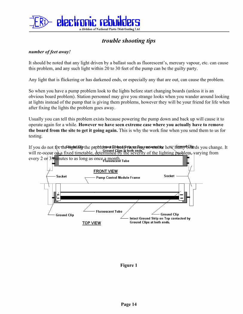
Gilbarco on their pumps install a ground strip down the length of their fluorescent tubes to try andprevent this magnetic field from inducing voltage on the tracks of the logic circuit boards in the pump.This is why it is extremely important to only install tubes with the ground strips on them, and tomake sure the ground strip is grounded by the metal ground pick up strips in the pump (see Figure1).
If however the Fluorescent Tubes or the Ballast starting them are faulty, they will be trying to startcontinually and will continue to fire the high voltage current down the tube. This not only wastes power,but will create a strong enough magnetic field to even overcome the ground strips and induce a voltageon the tracks of nearby boards. If these boards happen to be Logic or Processor boards a “bad or non-existent” memory location could be created causing “Logic Lock Up” or memory loss or both. TheMicro is looking for the bad address and can not find it.
Caution! When removing tubes that are suspected faulty in a pump with ground strips, turn off powerto the ballast first. If you do not the magnetic field is inducing an extremely high voltage in theground strip, and when you turn the tube to remove it, that strip is no longer grounded and you willget the full benefit of the voltage. So power off unless you enjoy picking yourself off of the ground a
trouble shooting tips
Page 14
number of feet away!
It should be noted that any light driven by a ballast such as fluorescent’s, mercury vapour, etc. can causethis problem, and any such light within 20 to 30 feet of the pump can be the guilty party.
Any light that is flickering or has darkened ends, or especially any that are out, can cause the problem.
So when you have a pump problem look to the lights before start changing boards (unless it is anobvious board problem). Station personnel may give you strange looks when you wander around lookingat lights instead of the pump that is giving them problems, however they will be your friend for life whenafter fixing the lights the problem goes away.
Usually you can tell this problem exists because powering the pump down and back up will cause it tooperate again for a while. However we have seen extreme case where you actually have to removethe board from the site to get it going again. This is why the work fine when you send them to us fortesting.
If you do not fix the lighting the problem will keep recurring no matter how many boards you change. Itwill re-occur on a fixed timetable, determined by the severity of the lighting problem, varying fromevery 2 or 3 minutes to as long as once a month.
Figure 1
trouble shooting tips
Page 15
No. 3 Re-Occurring problems on Gilbarco Modular Pumps
Published: Revised December 1998
This is a Tip that was passed on to us some years ago by a good friend!
Our friend had a relative who was experiencing re-occurring problems with one of his Gilbarco ModularHighline 111B Pumps. The pump displays kept cutting out. The Gilbarco distributor had replaced theRegulator Board once themselves and then every time the problem re-occurred, would send him another.Each time it was replaced it would work for a while and then fail.
On one of his visits our friend agreed to take a look. The only thing he could find was wrong was a greenwire (from the description it sounds like the main ground to the modular Power Supply, Plug 601, Pin 1,found on the rear of the Power Supply, behind the right rear display on the Highline) was not in itssocket but had been pushed back out. By our friend’s description it would appear it had never beeninserted properly to begin with during pump assembly.
Our friend inserted it properly and when the unit was powered back up it worked properly and did notfail again, as he checked back in a few weeks. He could not figure out how this had an impact, andneither can we, except that possibly the site had a bad neutral and when combined with no ground itpresented problems.
It only confirms our belief that before changing boards, you should ensure there are no power problems,such as low power, bad neutral lines or bad ground lines. Always check power between hot and neutral,and hot and ground. You should always get exactly the same voltage reading.
Our thanks and our tip of the hat to Terry McCartney of Kootenay Valley Petroleum Service!
trouble shooting tips
Page 16
No. 4 The Hot Black HeadPublished: July 1989
HEAT BUILD UP IN GILBARCO HIGHLINE BLACK PAINTED HEADS
We have recently came across a failure on W1513-Gl and W1854-Gl Regulator Interface boards whichbrought to our attention a possible area of concern.
The problem symptom was a reoccurring Pulser Fail signal (Flashing PPU "Price/Blank" or "Price/020")on a Highline with the Black Painted head (mostly Esso Pumps).
Changing the board cured the problem, however when we were running tests on the board, we found thateven new boards with new components were marginal at best. Here is what we found.
On the faulty board we found that the Transistors in the Pulser Fail Circuit gave a Pulser fall signal whenthey were heated to 49.2 deg. C (120.56 deg. F). We then ran tests on new boards and on the faulty boardwith new transistors and found that they all gave a Pulser fall signal at approximately 54 deg. C (129deg. F). All of these temperatures including the lower fail temperature are extremely high, and wewondered how they could get that high in the pump.
We realized that when Exxon originally requested the Black painted head, they were warned by Gilbarcothat they would experience a 20 to 30 percent higher failure rate because the temperature would increaseby that amount in a vented head.
We however have found the heads are not necessarily vented for two reasons, one of which is curable.
The first reason we have discovered is that during painting of the head, Gilbarco have been covering thevents with a small round sticker in order to mask them. These have not necessarily been removed priorto shipment. (We have a brand new Modular pump in our shop that still has these stickers in place.)These can and should be removed in the field. (It should be checked at commissioning, but do not bet onit. Check it yourself.)
The second reason the vents get covered is by the installation of Customer Preset Panel Boxes. we knowof no way of curing this without a design change by Gilbarco. (Field modification is possible but youwould be changing a CSA approved design.)
If you run into this situation your only cures are trying another board which may have a highertemperature tolerance, make sure the vents are not covered (difficult with Customer Preset), and if at allpossible shade the head from direct sunlight.
trouble shooting tips
Page 17
If none of the above help or can be done, powering the head down whenever this occurs and letting itcool off before powering back up may be your only solution.
No. 5 The Noisy Pump That Does not Pump
VAPOR PRESSURE AND ITS EFFECT ON PUMPING WITH A SUCTION PUMP
There seems to be some confusion and possibly a lack of knowledge over what many call " VAPORLock" in pumping systems. We are going to attempt, we hope, to clarify and not confuse the situation,and maybe pass on some information you did not have before.
"VAPOR Lock" is really a misnomer as nothing is "locked". It may seem that the pump has quitpumping but it has not. What has happened is that the Gasoline has turned from a liquid to a gas (orVAPOR). Because the Pump unit can no longer get liquid it "Cavitates", becoming very noisy, withvibration and slows its delivery dramatically.
However as most Service Station Pumps are positive displacement pumps (this means they must movesomething or something breaks) they are in fact pumping and what they are pumping is the gas or vapor.This gas or vapor is being discharged through the air eliminator if it is working properly, and is visibleunder right light conditions. It would be highly visible if you ignited it! Therefore it is not a conditionwhere you want to leave the pump running.
Why did the liquid Gasoline turn to a gas? Well each liquid has a given "VAPOR Pressure" at giventemperatures. This VAPOR Pressure is the lowest pressure which must be maintained on the liquid forthe current temperature to keep it in liquid state.
What makes the situation confusing is that this pressure increases with temperature, and varies fromliquid to liquid. Gasolines have a variety of VAPOR Pressures dependent upon the additives in them.Thus unleaded are different than leaded, premiums different than regular and winter grades different thansummer grades.
A plus factor however is that at most ambient temperature ranges the VAPOR Pressure of Gasolines isless than normal atmospheric pressure, thus it will stay in liquid state without additional pressure beingapplied to it. This is not the case with liquids such as Propane which must be kept in a pressurizedcontainer to keep them liquid as atmospheric pressure alone will not do it.
Back to our Service Station Pump unit that is noisy and slow; how can we determine if we have gonebelow VAPOR Pressure? The pump will cavitate if It can not get liquid.
A pump that is cavitatinq is:NoisyFull of vibration
trouble shooting tips
Page 18
experiencing a fluctuating or high Vacuum reading on Suction side.experiencing a Low Pressure reading on Discharge side.has extremely low flow If any.
To determine if we in fact are trying to pump below the VAPOR Pressure of the liquid we need thefollowing information:
A. The VAPOR Pressure of the Fuel and its current temperature.The temperature should be measured at the discharge of the pump as the temperature in thepump and the lines will probably be higher than in the tank, particularly if there is not muchcover, and asphalt instead of concrete over the lines. However it would be of interest to knowthe temperature in the tank as well.
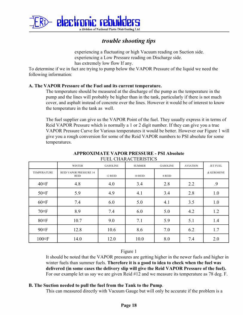
The fuel supplier can give us the VAPOR Point of the fuel. They usually express it in terms ofReid VAPOR Pressure which is normally a 1 or 2 digit number. If they can give you a trueVAPOR Pressure Curve for Various temperatures it would be better. However our Figure 1 willgive you a rough conversion for some of the Reid VAPOR numbers to PSI absolute for sometemperatures.
APPROXIMATE VAPOR PRESSURE - PSI AbsoluteFUEL CHARACTERISTICS
WINTER GASOLINE SUMMER GASOLINE AVIATION JET FUEL
TEMPERATURE REID VAPOR PRESSURE 14REID 12 REID 10 REID 8 REID
& KEROSENE
40NF 4.8 4.0 3.4 2.8 2.2 .9
50NF 5.9 4.9 4.1 3.4 2.8 1.0
60NF 7.4 6.0 5.0 4.1 3.5 1.0
70NF 8.9 7.4 6.0 5.0 4.2 1.2
80NF 10.7 9.0 7.1 5.9 5.1 1.4
90NF 12.8 10.6 8.6 7.0 6.2 1.7
100NF 14.0 12.0 10.0 8.0 7.4 2.0
Figure 1It should be noted that the VAPOR pressures are getting higher in the newer fuels and higher inwinter fuels than summer fuels. Therefore it is a good to idea to check when the fuel wasdelivered (in some cases the delivery slip will give the Reid VAPOR Pressure of the fuel).For our example let us say we are given Reid #12 and we measure its temperature as 78 deg. F.
B. The Suction needed to pull the fuel from the Tank to the Pump.This can measured directly with Vacuum Gauge but will only be accurate if the problem is a
trouble shooting tips
Page 19
blocked line or vent where you will get a steady high reading.
It can however be calculated (comparing this to the actual reading will determine if the line is blocked.)To do this we need the following information:
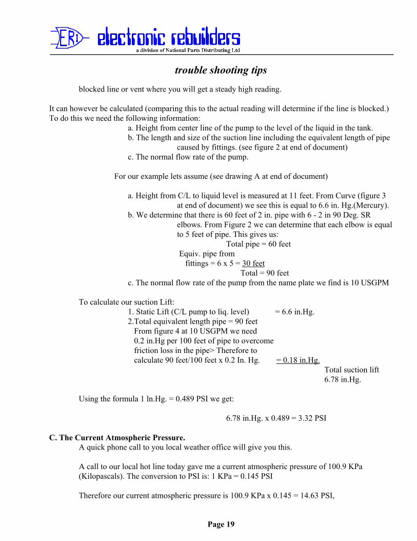
a. Height from center line of the pump to the level of the liquid in the tank.b. The length and size of the suction line including the equivalent length of pipe
caused by fittings. (see figure 2 at end of document)c. The normal flow rate of the pump.
For our example lets assume (see drawing A at end of document)
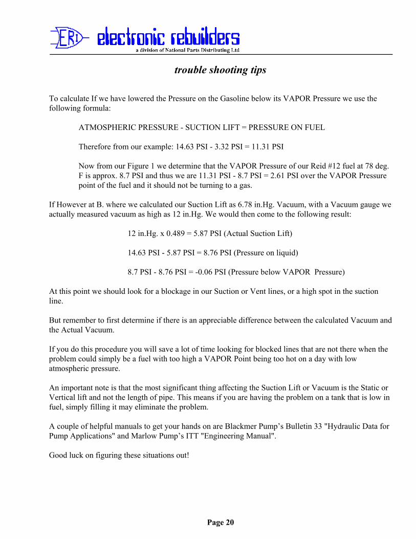
a. Height from C/L to liquid level is measured at 11 feet. From Curve (figure 3at end of document) we see this is equal to 6.6 in. Hg.(Mercury).
b. We determine that there is 60 feet of 2 in. pipe with 6 - 2 in 90 Deg. SRelbows. From Figure 2 we can determine that each elbow is equalto 5 feet of pipe. This gives us:
Total pipe = 60 feet Equiv. pipe from fittings = 6 x 5 = 30 feet
Total = 90 feetc. The normal flow rate of the pump from the name plate we find is 10 USGPM
To calculate our suction Lift: 1. Static Lift (C/L pump to liq. level) = 6.6 in.Hg.
2.Total equivalent length pipe = 90 feet From figure 4 at 10 USGPM we need
0.2 in.Hg per 100 feet of pipe to overcome friction loss in the pipe> Therefore to calculate 90 feet/100 feet x 0.2 In. Hg. = 0.18 in.Hg. Total suction lift
6.78 in.Hg.
Using the formula 1 ln.Hg. = 0.489 PSI we get:
6.78 in.Hg. x 0.489 = 3.32 PSI
C. The Current Atmospheric Pressure. A quick phone call to you local weather office will give you this.
A call to our local hot line today gave me a current atmospheric pressure of 100.9 KPa(Kilopascals). The conversion to PSI is: 1 KPa = 0.145 PSI
Therefore our current atmospheric pressure is 100.9 KPa x 0.145 = 14.63 PSI,
trouble shooting tips
Page 20
To calculate If we have lowered the Pressure on the Gasoline below its VAPOR Pressure we use thefollowing formula:
ATMOSPHERIC PRESSURE - SUCTION LIFT = PRESSURE ON FUEL
Therefore from our example: 14.63 PSI - 3.32 PSI = 11.31 PSI
Now from our Figure 1 we determine that the VAPOR Pressure of our Reid #12 fuel at 78 deg.F is approx. 8.7 PSI and thus we are 11.31 PSI - 8.7 PSI = 2.61 PSI over the VAPOR Pressurepoint of the fuel and it should not be turning to a gas.
If However at B. where we calculated our Suction Lift as 6.78 in.Hg. Vacuum, with a Vacuum gauge weactually measured vacuum as high as 12 in.Hg. We would then come to the following result:
12 in.Hg. x 0.489 = 5.87 PSI (Actual Suction Lift)
14.63 PSI - 5.87 PSI = 8.76 PSI (Pressure on liquid)
8.7 PSI - 8.76 PSI = -0.06 PSI (Pressure below VAPOR Pressure)
At this point we should look for a blockage in our Suction or Vent lines, or a high spot in the suctionline.
But remember to first determine if there is an appreciable difference between the calculated Vacuum andthe Actual Vacuum.
If you do this procedure you will save a lot of time looking for blocked lines that are not there when theproblem could simply be a fuel with too high a VAPOR Point being too hot on a day with lowatmospheric pressure.
An important note is that the most significant thing affecting the Suction Lift or Vacuum is the Static orVertical lift and not the length of pipe. This means if you are having the problem on a tank that is low infuel, simply filling it may eliminate the problem.
A couple of helpful manuals to get your hands on are Blackmer Pump’s Bulletin 33 "Hydraulic Data forPump Applications" and Marlow Pump’s ITT "Engineering Manual".
Good luck on figuring these situations out!
trouble shooting tips
Page 21
SELF CONTAINED (SUCTION) PUMPSTypical Installation Diagram
Drawing A
FRICTION LOSS IN VALVES AND FITTINGShown in approximate equivalent length of straight pipe in feet
Type of Fitting 1 1/2in 2in 3in
Gate Valve - Fully Open 0.95 1.2 1.7
Globe Valve - Open 42 51 80
Angle Valve - Open 20 30 40
Standard Tee - through side outlet 9 12 16
Standard Tee - straight through 2.8 3.5 5
Standard Elbow 4.5 5.0 8
trouble shooting tips
Page 22
Medium Sweep Elbow 3.5 4.5 7
Long Sweep Elbow 2.8 3.5 5Figure 2
Figure 3
trouble shooting tips
Page 23
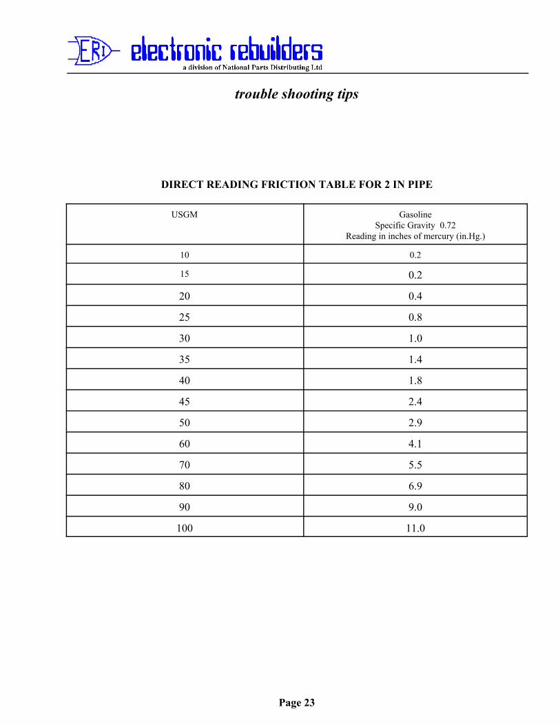
DIRECT READING FRICTION TABLE FOR 2 IN PIPE
USGM GasolineSpecific Gravity 0.72
Reading in inches of mercury (in.Hg.)
10 0.2
15 0.2
20 0.4
25 0.8
30 1.0
35 1.4
40 1.8
45 2.4
50 2.9
60 4.1
70 5.5
80 6.9
90 9.0
100 11.0
trouble shooting tips
Page 24
No. 6 Gilbarco Pump/Dispenser ResetsPublished: Revision 1, November 15, 1999
Gilbarco Pre-Modular
Pre-Modular pumps can only be Master Reset. This means all memory will be lost. Howeverthe only memory these pumps had was in effect the same as the RAM memory on a modular,meaning “price settings” and “totalizer readings”. This “Master” reset is accomplished byshorting or jumping points on the Logic Board. It also varies from pump to pump depending onthe model. We will deal with the three basic models that were sold in Canada.
Highline 111B with T12472-G1 or W1520-G1 or W1520-G2 Logic Boarda. Turn off Power to the Pump.b. Remove Plug P16 from the Bottom Centre of the Board.c. Short across the base of capacitor C11 with a knife blade or screwdriver for ten
seconds.d. Remove the short and replace plug P16.e. Turn on power to the pump and observe prices should now be zeroed.
Highline 111B or Salesmaker 4 with W2061-G1 Logic Boards
a. Insert a Jumper Jack in position JP-6 on the Logic Boardb..Turn off Power to the Pump.c. Turn on Power to the Pump.d. Remove the Jumper Jack from JP-6.
Caution! Ensure you remove the Jumper. If you leave it in place, the Logic Boardwill reset every time there is a power failure and it comes back on!
MPD-2/C with W1523-G1 Z80 Logic Board
a. Place a Jumper Jack on the pins marked Master Reset or MR on the Logic Board.b. Turn Off Power to the Pump.c. Turn On Power to the Pump.d. Remove the Jumper Jack from the Logic Board.
Caution! Ensure you remove the Jumper. If you leave it in place, the Logic Boardwill reset every time there is a power failure and it comes back on!
trouble shooting tips
Page 25
No. 7 - T16226-G Main Display Jumper SettingsPublished: Revision 2 January 1995
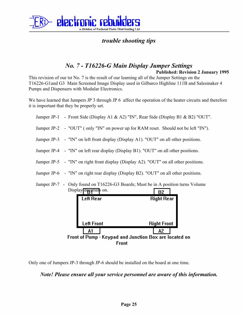
This revision of our tst No. 7 is the result of our learning all of the Jumper Settings on theT16226-G1and G3 Main Screened Image Display used in Gilbarco Highline 111B and Salesmaker 4Pumps and Dispensers with Modular Electronics.
We have learned that Jumpers JP 3 through JP 6 affect the operation of the heater circuits and thereforeit is important that they be properly set.
Jumper JP-1 - Front Side (Display A1 & A2) "IN", Rear Side (Display B1 & B2) "OUT".
Jumper JP-2 - "OUT" ( only "IN" on power up for RAM reset. Should not be left "IN").
Jumper JP-3 - "IN" on left front display (Display A1). "OUT" on all other positions.
Jumper JP-4 - "IN" on left rear display (Display B1). "OUT" on all other positions.
Jumper JP-5 - "IN" on right front display (Display A2). "OUT" on all other positions.
Jumper JP-6 - "IN" on right rear display (Display B2). "OUT" on all other positions.
Jumper JP-7 - Only found on T16226-G3 Boards; Must be in A position turns Volume Display decimals on.
Only one of Jumpers JP-3 through JP-6 should be installed on the board at one time.
Note! Please ensure all your service personnel are aware of this information.
trouble shooting tips
Page 26
No. 8 - That darn Gilbarco Code 34Revised November 1999
Gilbarco Modular Code 34 - Battery Test Failure
We have been getting a lot of calls lately on Gilbarco Modular pumps showing a flashing code 34 andprice, which indicates the battery failed a test. Many Contractors have been changing Controller Boardsand Regulator Boards to no avail. If the Controller has version 53.4* or higher software it is the leastlikely cause of the problem and the Regulator is probably the second least likely.
* Controller Boards with a lower software version than 53.4 should have the software changed asthere were problems with the battery test circuit on earlier versions. Contact your GilbarcoDistributor for new software.
To understand a little better why it does this let us look at how the code 34 occurs.
The pump periodically does a battery test on its own. In particular, it does one 15 minutes after power upif it has been turned off. This one occurring fifteen minutes after power up is usually the one that causesthe code 34. When you power the pump down at night, the pump is under battery power for 15 minutes.This is to enable the display of a last transaction. As a result the Battery may drop from its normalcharged voltage (new battery 13.2V) by a couple of volts. When the pump is powered up the Batterystarts to charge but at 15 minutes, the pump does a battery test by feeding battery power through a largeresistor mounted on the power supply for 15 seconds, simulating a display last transaction. This maydrop the Battery voltage by more than one volt. At the end of the test the Controller checks the Batteryvoltage and if less than 11 volts it fails the test.
Now the Batteries used, are just like a car battery. Their efficiency drops with temperature and with lackof use. So if it is cold the Battery may not charge as high or it may drop more voltage during the test.New Batteries may not be good either unless the supplier’s recharge them on his shelves every sixmonths (we do). Therefore cold can be a major factor and shelf life can be a major factor.
To check it, perform a Battery test under Command Code 9. If the test fails, check your battery voltage.If it is low, the Battery needs to be replaced. But before replacing it something else that should bechecked is that you have very good connections from the Battery to the Regulator Board and from theRegulator Board to the Battery Test resistor.
To check this turn of power to the pump and then turn off the battery by pressing “Clear” and then“Enter” on the keypad of the pump. Then with an ohmmeter check from Pin 5 of plug J502 (usually anorange plug) on top of the Regulator Board to the + (Positive) terminal of the Battery. You should haveless than 1 Ohm resistance. If you do not check Plug J601/P601 at the rear of the Power Supply (makesure pins are not centred in sockets) and then check the top (Battery) fuse on the Power Supply (makesure it is both good, and seated properly).
trouble shooting tips
Page 27
If this is OK then check from Pin 6 of Plug J502 to the - (Negative) terminal of the Battery. If it is bad,then check plug J601/P601 again.
If these are both OK then check from Pin 6 of plug J502 to the end of the Test Resistor (mounted besidethe Battery). Check both ends of the Resistor and one end should be less than 1 Ohm. If bad again checkplug J601/P601.
If all are good then try a new Battery, letting it charge to 13 volts before trying a Battery test (the pumpwill do it automatically 15 minutes after power up). If it still fails then and only then should you trychanging the Regulator Board.
The Controller Board should be your last resort!
trouble shooting tips
Page 28
No. 9 - “I changed the Board and Now the Dumb Modular is flashing code31 or 35"
Revised December 1999Flashing Code 31 or 35 on Gilbarco Modular Pumps/Dispensers
Boy! Can this be frustrating or what? You change the board, or Battery or Pulser to cure a problem andthen the pump flashes error code 31 or 35 at you, which means you have to do a RAM reset (CommandCode 6). This removes Price and Totalizer memory and you have re-enter both.
Unless it was a faulty Battery, blame yourself! You did not turn off the Battery before unpluggingsomething and the Controller Board, because it did not have a chance to go through a normal shut downprocedure, figures it screwed up its memory. Thus the error code.
Make the following a hard and fast procedure when changing anything on a Modular pump.
Step 1. - Turn off Power to the head, either with a Circuit Breaker, or by pulling the bottom Fuseon the Power Supply (do not pull the top one as it is the Battery Fuse and will cause yourproblem). The displays should now only have the decimal places lit (if they are not theBattery was no good or the top Fuse was blown and you can quit blaming yourself).
Step 2. - If they did stay lit, turn off the Battery. To do this press “CLEAR” and “ENTER” on thepump keypad. The decimal places on the displays should now go out.
Step 3. - Now unplug and change anything you have to change.
If the Battery was dead or the Fuse was blown (as indicated in Step 1) or had been disconnected beforepowering the unit down, you will get error code 31 or 35 after you power the unit up.
Of course make sure you have plugged every thing back in before powering the unit back up!
trouble shooting tips
Page 29
No. 10 Turn off that Power 10 May 1994
Warning! Turn offthe Power before changing any circuit board or component in
any piece of electronic equipment (this includes Pumps, Dispensers, Consoles andPrinters).
We have recently received back a number of boards under warranty which have obviously beenchanged with power on and accidentally shorted to frame or other metal object. This results inmost components on the board being damaged and means they must be changed. This drives upthe cost of the board repairs and results in a higher end cost to you.
However the cost is the least important thing! The most important consideration is yoursafety! On some boards there are high voltages present. In the case of Gilbarco displays this is ashigh as 180 Volts DC.
If you happened to be between the display and ground you would be picking yourself off of theground about 50 feet from where you caused the short. If your heart happened to be in that samepath, you would be picked up by a paramedic or the coroner!
This also brings up another important point! You should in normal practice be grounded whenhandling circuit boards to prevent damage from static electricity. Make sure that you aregrounded with an approved static wrist or ankle strap that has a built in resistor to prevent highcurrent passing through your body in the event you short something that is live.
Also make sure when turning off Power that you use proper shut down procedures for theequipment you are changing to avoid creating yourself other problems.
Prevent damage to components, yourself and others - Turn off thePower!
trouble shooting tips
Page 30
Figure 1
No. 11 Kraus Type A and B SKIL184 Software SwappingJanuary 1995
It has come to our attention that Contractors in the field are swapping Type A (CP1.2) Software for TypeB (ATC2.4) Software on SKIL 184 ATC Boards, or visa versa, as a result of them changing SKIL 152Assy 15 Controller Software.
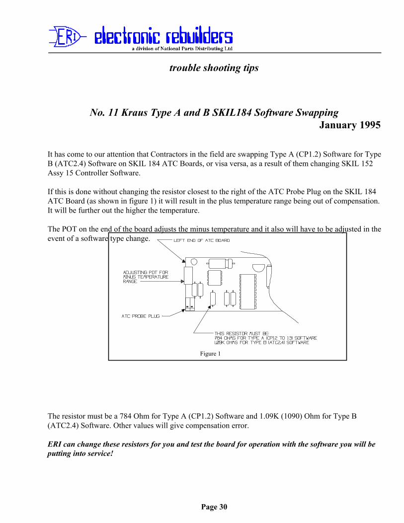
If this is done without changing the resistor closest to the right of the ATC Probe Plug on the SKIL 184ATC Board (as shown in figure 1) it will result in the plus temperature range being out of compensation.It will be further out the higher the temperature.
The POT on the end of the board adjusts the minus temperature and it also will have to be adjusted in theevent of a software type change.
The resistor must be a 784 Ohm for Type A (CP1.2) Software and 1.09K (1090) Ohm for Type B(ATC2.4) Software. Other values will give compensation error.
ERI can change these resistors for you and test the board for operation with the software you will beputting into service!
trouble shooting tips
Page 31
No. 12 - Dead Batteries on Gilbarco® TCR™-G2 Memory Expansion Boards
February 1995
We have found the main reason for Batteries going dead, on the T16749-G1 Memory Expansion Boardon the TCR-G2 Gilbarco Cash Register Consoles, is leakage between the Memory Circuits and the 5VDC Logic circuits on the W2067 Logic Board during a power down.
If this occurs the Battery on the Memory Expansion Board is powering all IC’s on the Logic Board andnot just the RAM and Clock circuits. The higher the leakage the faster the Battery will drain. If theBattery drains below 1.5 VDC memory loss will occur and the probability that the Battery will rechargeon power up is slim. This will then cause memory loss on every power down of the Register.
You can determine, with a simple test, if this leakage was the cause of the Battery failure once you havereplaced the Memory Expansion Board (or at least the battery on the board).
1. Ensure the Memory Expansion Board is installed properly, plugged solidly into P110 on theLogic Board, and that the Battery Jumper is in the “JP2-B” (ON) position and JP1 is in the“ENABLE” position.
2. Do not turn on the TCR-G2 power!
3. With a digital Voltmeter measure voltage at the +5 VDC Logic Test Point on the W1544-G1Regulator Board as shown on page 43 of the Gilbarco MDE-2214B Service Manual (Negativelead on the positive, system ground, end of Capacitor C2 and the positive lead on the + end ofCapacitor C40). You should read 0 VDC if the Logic Board is good.
If you read any voltage, even as low as 0.5 VDC, there is leakage occuring and the Logic Board shouldbe replaced.
Please Note! ERI does test all its rebuilt Logic Boards for this problem.
trouble shooting tips
Page 32
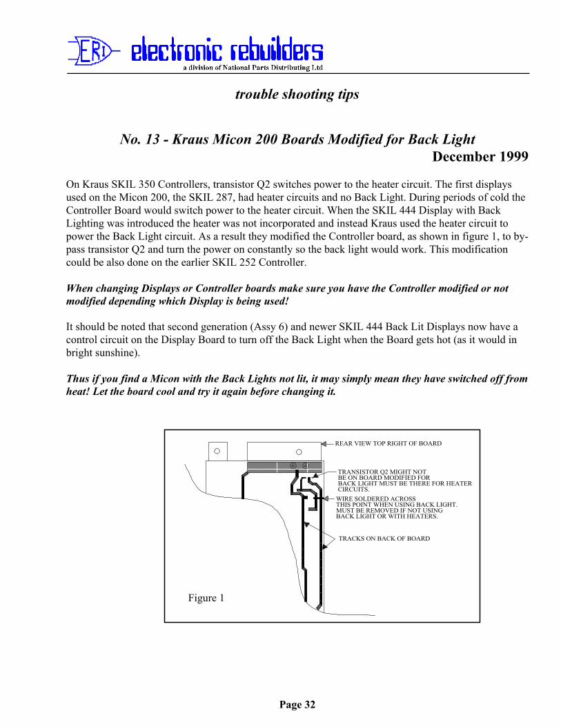
WIRE SOLDERED ACROSSTHIS POINT WHEN USING BACK LIGHT.MUST BE REMOVED IF NOT USINGBACK LIGHT OR WITH HEATERS.
TRANSISTOR Q2 MIGHT NOTBE ON BOARD MODIFIED FORBACK LIGHT MUST BE THERE FOR HEATERCIRCUITS.
REAR VIEW TOP RIGHT OF BOARD
Figure 1
TRACKS ON BACK OF BOARD
No. 13 - Kraus Micon 200 Boards Modified for Back LightDecember 1999
On Kraus SKIL 350 Controllers, transistor Q2 switches power to the heater circuit. The first displaysused on the Micon 200, the SKIL 287, had heater circuits and no Back Light. During periods of cold theController Board would switch power to the heater circuit. When the SKIL 444 Display with BackLighting was introduced the heater was not incorporated and instead Kraus used the heater circuit topower the Back Light circuit. As a result they modified the Controller board, as shown in figure 1, to by-pass transistor Q2 and turn the power on constantly so the back light would work. This modificationcould be also done on the earlier SKIL 252 Controller.
When changing Displays or Controller boards make sure you have the Controller modified or notmodified depending which Display is being used!
It should be noted that second generation (Assy 6) and newer SKIL 444 Back Lit Displays now have acontrol circuit on the Display Board to turn off the Back Light when the Board gets hot (as it would inbright sunshine).
Thus if you find a Micon with the Back Lights not lit, it may simply mean they have switched off fromheat! Let the board cool and try it again before changing it.
trouble shooting tips
Page 33
No. 14 Those bugs bite!Published: December 1998
One of the summer plagues we face in Canada are a tiny little bug with a big bite we commonly call “NoSee’ums”! Well these little critters also bite electronics!
They manage to get into pump heads through the tiniest places, unsealed doors or loose panels, throughventilation vents, etc. Once inside the pump head they like to get cozy with warm IC’s. These are usuallyfound on Regulator or Power Supply boards, and if there is enough voltage such as in Gilbarco ModularPumps and to a lesser extent Tokheim Pumps the little fly gets electrocuted and in the process usuallycauses enough of a short to take out the circuit board.
With a magnifying glass and even sometimes with the naked eye you can find these little fellows on theblown board with their feet up in the air, having committed suicide at the expense of the board.
The only cure to this problem, if you find them on a blown board, is to prevent them getting in. Ensureall openings are sealed. This does present a problem with vents in that they are designed to cool thehousing. Most of these vents have a screen or very small openings, but as any of you who haveexperienced these little fellow know they can get through a window screen. If you put in a finer meshscreen you will restrict air flow.
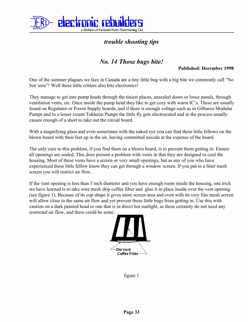
If the vent opening is less than 3 inch diameter and you have enough room inside the housing, one trickwe have learned is to take wire mesh drip coffee filter and glue it in place inside over the vent opening(see figure 1). Because of its cup shape it gives more screen area and even with its very fine mesh screenwill allow close to the same air flow and yet prevent these little bugs from getting in. Use this withcaution on a dark painted head or one that is in direct hot sunlight, as these certainly do not need anyrestricted air flow, and there could be some.
figure 1
trouble shooting tips
Page 34
No 15 Sealing D&H Technologies Pulsers to Prevent Water Wicking upShaft
Published: July 2, 1999Water is the biggest cause of Pulser Failure on D&H EQ30 Heads! Almost 90 percent of the units beingreturned under warranty have signs of moisture having been present on their shaft.
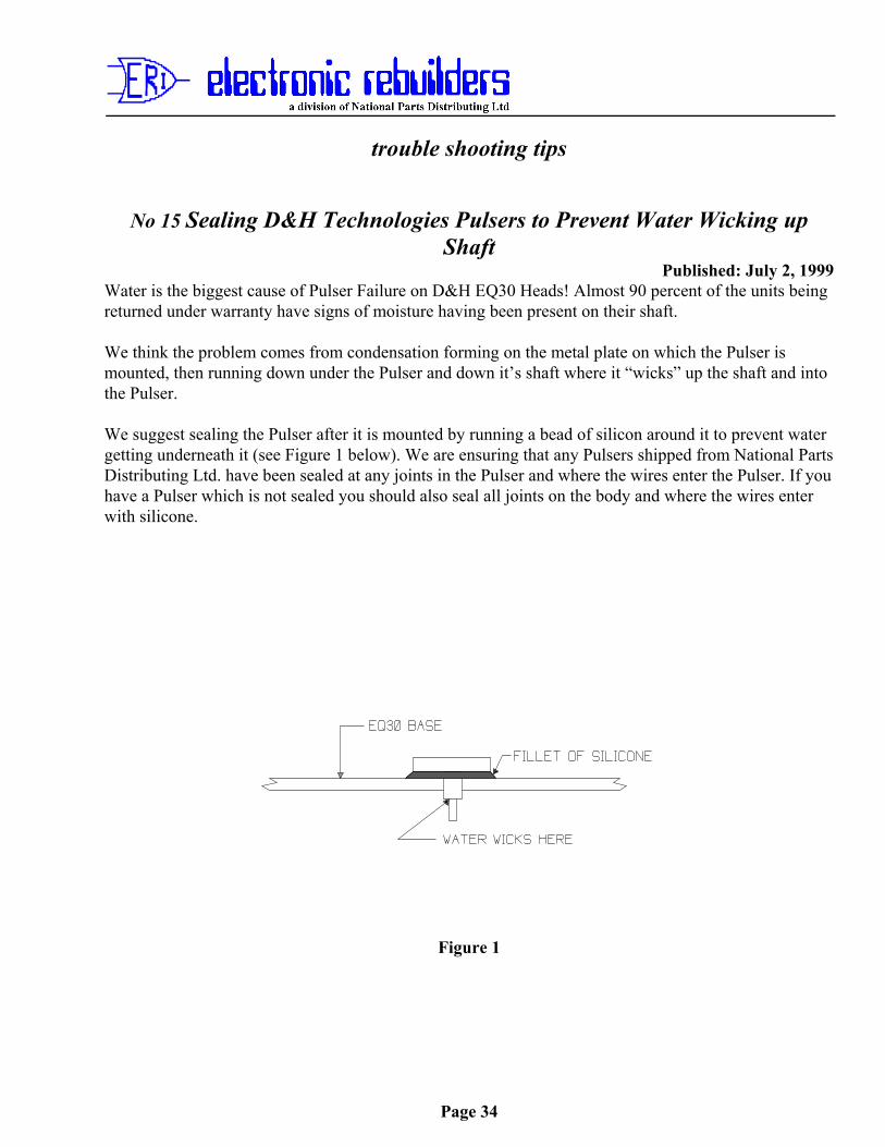
We think the problem comes from condensation forming on the metal plate on which the Pulser ismounted, then running down under the Pulser and down it’s shaft where it “wicks” up the shaft and intothe Pulser.
We suggest sealing the Pulser after it is mounted by running a bead of silicon around it to prevent watergetting underneath it (see Figure 1 below). We are ensuring that any Pulsers shipped from National PartsDistributing Ltd. have been sealed at any joints in the Pulser and where the wires enter the Pulser. If youhave a Pulser which is not sealed you should also seal all joints on the body and where the wires enterwith silicone.
Figure 1
trouble shooting tips
Page 35
No. 16 - Installing DG8340 Esco Printers with Gilbarco Transac ConsolesDate Issued: January 2000
We recently ran into a problem when installing DG8340 Esco Printers with a Transac 12 (G in this case)console.
When trying to print receipts or reports the printer would print a line or 2 lines then carriage return 12blank lines then print another 2 lines. If you turned off power to the printer without disconnecting itsdata cable, it would appear to “lock up” the Console. It really had not; it had simply put the Console intoa “slow” mode and it would take up to a minute to react to key strokes.
Upon discussion with the station Manager we discovered that this particular Console had originally hadan “Esso” Repos unit attached to it, which the station Manager had removed because it was “locking up”the Console. He then had a DOT 2® Printer installed which had also caused “lock ups” and eventuallygot so worn it needed to be replaced. As the DOT 2® is no longer made and printer mechanism hadbecome obsolete, the manager decided to replace it with the DG8340 and the new problems began. Uponquestioning we discovered that he was sure memory had not be blown in the Console when the Reposwas removed, and of course it had not when he had the DG8340 installed. After the memory was blownin the Console the DG8340 worked perfectly. Therefore:When installing a DG8340, where it is known that either a Repos unit or a DOT 2® Printer hadpreviously been installed on the Printer Port of a Transac Console, blow the memory in the Consoleas follows:
Transac 12A or B1. Remove AC power from the Console.2. Unplug the Battery from the Logic Board.3. Short across the 2 connectors the Battery was plugged into.4. Reconnect the Battery and restore AC power.
Transac 12C with T15899 and T16249 Logic Boards1. Remove AC power from the Console.2. Remove JP3 from the Logic Board.3. Apply AC power for 15 seconds, then remove power again.4. Replace JP3 and restore AC power.
Transac 12C and Transac 12G with T16399 and later Logic Boards.1. Remove AC power from the Console.2. Remove JP3 and move JP69A to JP69B on the Logic Board.3. Apply AC power for 15 seconds, then remove power again.4. Replace JP3 and move JP69B back JP69A.5. Restore AC power to the Console.
trouble shooting tips
Page 36
Important Note! Ensure the manager has all information from the console first, and make sure you have noted any
Grade mapping and Programming of the Console before performing this procedure!
trouble shooting tips
Page 37
No. 17 Esco Genesis and D&H EQ 30 Heads Pulse RatesPublished: December 2000
When setting up D&H EQ30 Heads you should set up Code 02 for Penny Console and Code 03 forPennY .004 or Vol .004 depending on wether you are going to pulse off of Money or Volume (TheConsole can be set to accept Volume Pulses and calculate the Money).
We have found many people setting the head for Vol .008 (D&H Default) or PennY.008 . The followingwill give you and idea of the limitations doing that.
The Esco Genesis will start to miss pulses at around 3500 pulses/min ($35.00 /min) when the head is setat PennY.008 . It wil not start to miss pulses until about 7000 pulses/min ($70.00 /min) when set atPennY.004 . The higher the Price continues to rise per Litre the more problems you will encounter withthe PennY.008 setting. The following will give you a better idea:
Setting PennY.008 Setting PennY.004
70 lpm = maximum price $0.50 per l 70 lpm = maximum price $1.00 per l60 lpm = maximum price $0.58 per l 60 lpm = maximum price $1.16 per l50 lpm = maximum price $0.70 per l 50 lpm = maximum price $1.40 per l40 lpm = maximum price $0.875 per l 40 lpm = maximum price $1.75 per l35 lpm = maximum price $1.00 per l 35 lpm = maximum price $2.33 per l
This is of course based on a 10 PPU per unit setting in the head and the Console at 1 (1 to 1, this is thedefault setting).
If you run both the head and Console on Volume the accuracy on money suffers due to round off. Thehigher the price the worse it gets. This is due to the fact the head is calculating the money based on1/1000 of a Liter, and the Console is calculating it on 1/100 of a litre.
The best accuracy can be achieved by setting the head at Vol.004 and 100PPU and the console at 1 (1to1) as you set it for Money. If you set the head at 10PPU the console must be set at /10 (1 to 10), andthe round off will be to 1/10 of a liter instead off 1/100 of a litre.
It should be noted that at 100 PPU and Vol.004 you are limiting your maximum flow rate to around 70lpm so you really do not gain anything.
trouble shooting tips
Page 38
NO. 18 Installing C2000-K Progressive International Console with KrausMicon & MTI (D&H) EQ30 Heads - Issues
Published: October 2001
We have discovered a number of conditions where the C2000-K Console will not work or work correctlywith both Kraus Micon Heads and MTI (D&H) Eq30 Heads. We will deal with each of these below:
Kraus Micon Heads
Micon 100
SKIL 152 A15 Boards and must have version DANPMP3.1 or DANPMP3.2 Software.
SKIL 421 Boards must have version V7.03 Software.
Micon 200
SKIL 252 Boards must have version V6.3 Software. Note! Will not work on two tier pricing!
SKIL 350 Boards must have version V 7.03 or V1.09 Software. Note! Will not work on two tier pricing!
Micon 500
Units must have version V1.33 Software and be equipped with the optional piggyback SKIL 472 MNETInterface Board to provide serial interface. Note! Will not work on two tier pricing!
MTI (D&H) EQ30 Heads
CPU Board
Must have version V1.42 Software in order for shift reports to function properly.
Interface/Power Supply Board
Must be Revision 3 or 4 or a “Modified” Revision 1 or 2 board to enable Kraus MNET communication.
All boards show revision 2 on the front of the board and the actual revision number is only marked on therear of the board. Therefore for quick identification refer to Figure 1. Once you have established that youhave a revision 1 or 2 board you wil have to remove it from the Explosion Proof housing to determine if it ismodified. Modified version 1 or 2 boards will have a transistor and 2 resisters soldered to the back of theboard behind Microprocessor U1.
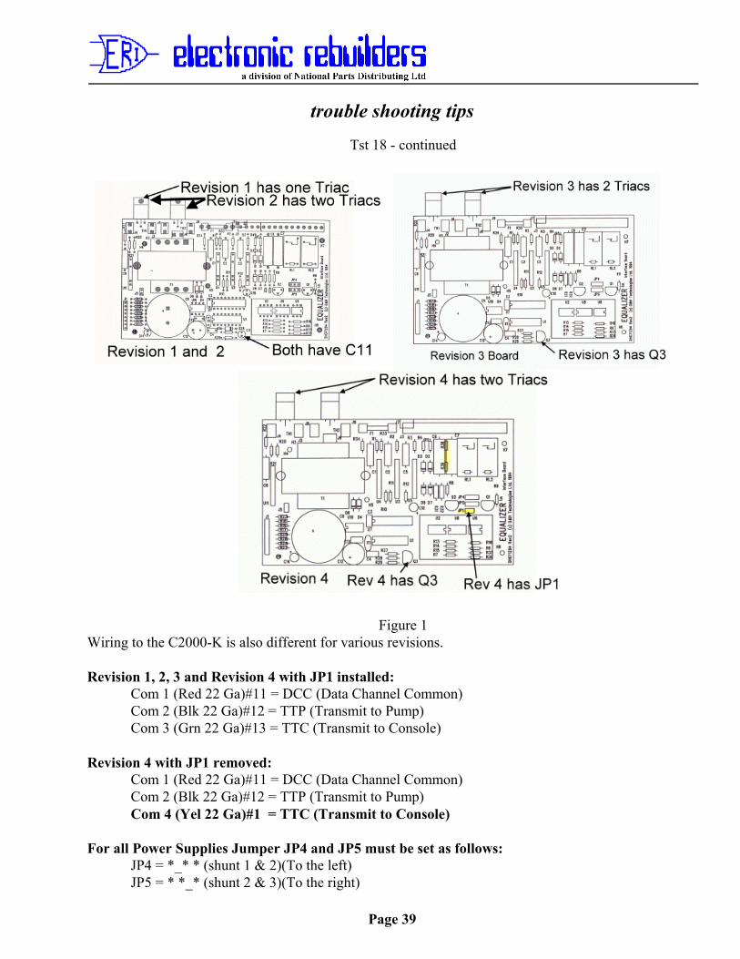
trouble shooting tips
Page 39
Tst 18 - continued
Figure 1Wiring to the C2000-K is also different for various revisions.
Revision 1, 2, 3 and Revision 4 with JP1 installed:Com 1 (Red 22 Ga)#11 = DCC (Data Channel Common)Com 2 (Blk 22 Ga)#12 = TTP (Transmit to Pump)Com 3 (Grn 22 Ga)#13 = TTC (Transmit to Console)
Revision 4 with JP1 removed:Com 1 (Red 22 Ga)#11 = DCC (Data Channel Common)Com 2 (Blk 22 Ga)#12 = TTP (Transmit to Pump)Com 4 (Yel 22 Ga)#1 = TTC (Transmit to Console)
For all Power Supplies Jumper JP4 and JP5 must be set as follows:JP4 = *_* * (shunt 1 & 2)(To the left)JP5 = * *_* (shunt 2 & 3)(To the right)
trouble shooting tips
Page 40
RELAY
J2RESETSWITCH
RED WIRETO PIN 2 ON CONTROLLERBATTERY CHARGE
BLUE WIRETO PIN 1ON CONTROLLER - RESET
RED WIRE TOBATTERY POSITIVE
J2 TO REMOTE HANDLESWITCH
J5 J6
J5 AND 6 ARE SWITCHEDCONTACTS OF THE RELAYAND ARE TO SWITCH #14 BRNAUTHORIZE WIRE
GROUND PAD
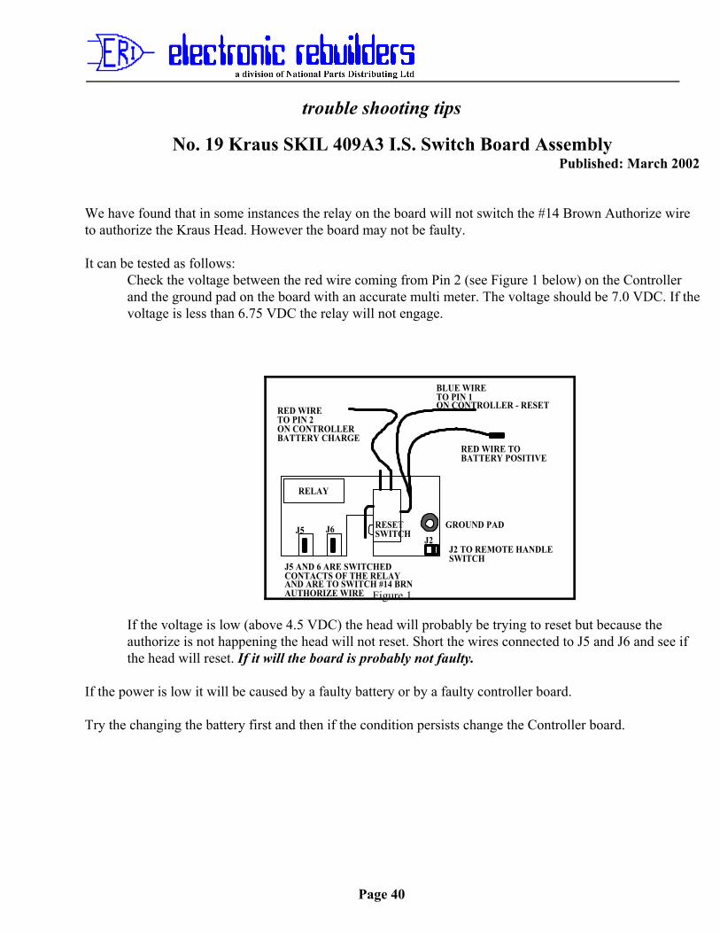
No. 19 Kraus SKIL 409A3 I.S. Switch Board AssemblyPublished: March 2002
We have found that in some instances the relay on the board will not switch the #14 Brown Authorize wireto authorize the Kraus Head. However the board may not be faulty.
It can be tested as follows:Check the voltage between the red wire coming from Pin 2 (see Figure 1 below) on the Controllerand the ground pad on the board with an accurate multi meter. The voltage should be 7.0 VDC. If thevoltage is less than 6.75 VDC the relay will not engage.
Figure 1
If the voltage is low (above 4.5 VDC) the head will probably be trying to reset but because theauthorize is not happening the head will not reset. Short the wires connected to J5 and J6 and see ifthe head will reset. If it will the board is probably not faulty.
If the power is low it will be caused by a faulty battery or by a faulty controller board.
Try the changing the battery first and then if the condition persists change the Controller board.

trouble shooting tips
Page 41
No 20 Totalizer Readings from Kraus Micon 100, 200 and 500 and MTI(D&H) EQ30 Retrofit Heads with Progressive International C2000-KConsole
Published: May 2002
We have learned that all of the above heads, which use Kraus Protocol, do not store a transaction in their Pump Totals so that it can be polled remotely until the next authorization. You can, however, read thecorrect totalizer at the pump using normal pump totalizer reading methods.
To compensate for this Progressive International have programmed the C2000-K so that it automaticallyadds the last sale to the polled total. We understand most other manuafacturers of serial equipment havedone this as well.
Thus there is no problem unless for some reason you perform a master reset on the Console. The Consolethen does not have the last sale in its memory.
If at that point you request Pump Totals from the pump without authorizing it and resetting it, you will get atotalizer reading that differs from the pump by the amount of the last sale on the pump.
This will only occur until you reset the pump, after a “Master” reset on the Console.
trouble shooting tips
Page 42
No. 21 - Installing C2000 Progressive International ConsolesPublished: May 2002
To avoid communication and Totalizer Problems when installingC2000 Progressive International Consoles, perform a Master reseton the Console, and on the Pumps you are connecting it to, beforeprogramming the Console and putting it on line.
Note! The console must be on line and communicating with thepumps before programming it!
trouble shooting tips
Page 43
TST No 22 - Checking and Correcting Receptacle Reversed Polarity beforeconnecting a Console, Printer or other Electronic Device.
Published: October 2002
What does reversed polarity mean? How can you tell, and what can you do about it.
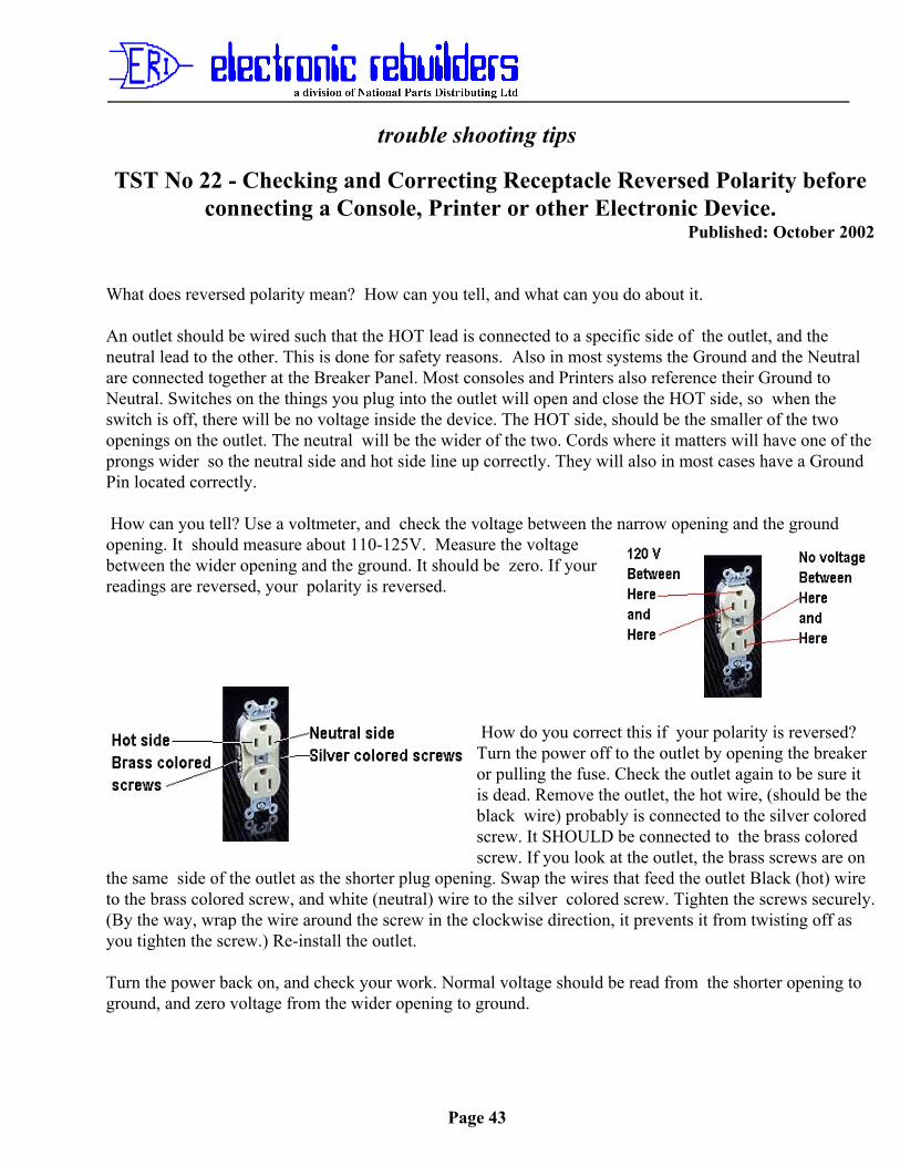
An outlet should be wired such that the HOT lead is connected to a specific side of the outlet, and theneutral lead to the other. This is done for safety reasons. Also in most systems the Ground and the Neutralare connected together at the Breaker Panel. Most consoles and Printers also reference their Ground toNeutral. Switches on the things you plug into the outlet will open and close the HOT side, so when theswitch is off, there will be no voltage inside the device. The HOT side, should be the smaller of the twoopenings on the outlet. The neutral will be the wider of the two. Cords where it matters will have one of theprongs wider so the neutral side and hot side line up correctly. They will also in most cases have a GroundPin located correctly.
How can you tell? Use a voltmeter, and check the voltage between the narrow opening and the groundopening. It should measure about 110-125V. Measure the voltagebetween the wider opening and the ground. It should be zero. If yourreadings are reversed, your polarity is reversed.
How do you correct this if your polarity is reversed? Turn the power off to the outlet by opening the breaker or pulling the fuse. Check the outlet again to be sure itis dead. Remove the outlet, the hot wire, (should be theblack wire) probably is connected to the silver coloredscrew. It SHOULD be connected to the brass coloredscrew. If you look at the outlet, the brass screws are on
the same side of the outlet as the shorter plug opening. Swap the wires that feed the outlet Black (hot) wireto the brass colored screw, and white (neutral) wire to the silver colored screw. Tighten the screws securely.(By the way, wrap the wire around the screw in the clockwise direction, it prevents it from twisting off asyou tighten the screw.) Re-install the outlet.
Turn the power back on, and check your work. Normal voltage should be read from the shorter opening toground, and zero voltage from the wider opening to ground.