triton 3d350hp diaphragm pump - graco · 311689g eng instructions/parts list triton® 3d350hp...
TRANSCRIPT

311689GENG
Instructions/Parts List
TRITON® 3D350HPDiaphragm Pump
Used to pump waterborne and solvent-based paints and catalysts.
Part No. 253707, Series D3:1 Ratio Air-Operated Double Diaphragm Pump, with BSPP Fittings
Part No. 253708, Series D3:1 Ratio Air-Operated Double Diaphragm Pump, with npt Fittings
0.6 MPa, 6 bar (88 psi) Maximum Air Input Pressure1.8 MPa, 18 bar (260 psi) Maximum Fluid Working Pressure
Important Safety InstructionsRead all warnings and instructions in this manual.Save these instructions.
TI1962A
II 2 G
2
ContentsWarning . . . . . . . . . . . . . . . . . . . . . . . . . . . . . . . . . . . 3Installation . . . . . . . . . . . . . . . . . . . . . . . . . . . . . . . . 5
General Information . . . . . . . . . . . . . . . . . . . . . . 5Tighten Threaded Connections . . . . . . . . . . . . . . 5Mounting the Pump . . . . . . . . . . . . . . . . . . . . . . . 6Air Line . . . . . . . . . . . . . . . . . . . . . . . . . . . . . . . . 7Fluid Suction Line . . . . . . . . . . . . . . . . . . . . . . . . 7Fluid Outlet Line . . . . . . . . . . . . . . . . . . . . . . . . . 7Grounding . . . . . . . . . . . . . . . . . . . . . . . . . . . . . . 9
Operation . . . . . . . . . . . . . . . . . . . . . . . . . . . . . . . . 10Pressure Relief Procedure . . . . . . . . . . . . . . . . 10Flush the Pump Before First Use . . . . . . . . . . . 10Starting and Adjusting the Pump . . . . . . . . . . . 10Pump Shutdown . . . . . . . . . . . . . . . . . . . . . . . . 10
Maintenance . . . . . . . . . . . . . . . . . . . . . . . . . . . . . . 11Lubrication . . . . . . . . . . . . . . . . . . . . . . . . . . . . 11Flushing and Storage . . . . . . . . . . . . . . . . . . . . 11Tighten Threaded Connections . . . . . . . . . . . . . 11Preventive Maintenance Schedule . . . . . . . . . . 11
Troubleshooting . . . . . . . . . . . . . . . . . . . . . . . . . . 12
Repair . . . . . . . . . . . . . . . . . . . . . . . . . . . . . . . . . . . 14Prepare the Pump for Repair . . . . . . . . . . . . . . . 14General Repair Notes . . . . . . . . . . . . . . . . . . . . 14Fault Indications . . . . . . . . . . . . . . . . . . . . . . . . 14Tools Required . . . . . . . . . . . . . . . . . . . . . . . . . 14Replace the Diaphragms . . . . . . . . . . . . . . . . . . 15Repair the Air Valve . . . . . . . . . . . . . . . . . . . . . . 17Replace the Ball Check Valves . . . . . . . . . . . . . 19Replace the Cylinder and Piston Seals . . . . . . . 21
Parts . . . . . . . . . . . . . . . . . . . . . . . . . . . . . . . . . . . . 23Technical Data . . . . . . . . . . . . . . . . . . . . . . . . . . . . 25Performance Charts . . . . . . . . . . . . . . . . . . . . . . . . 26Dimensions . . . . . . . . . . . . . . . . . . . . . . . . . . . . . . . 27Wall Mount Hole Pattern . . . . . . . . . . . . . . . . . . . . 27Torque Sequence . . . . . . . . . . . . . . . . . . . . . . . . . . 27Graco Standard Warranty . . . . . . . . . . . . . . . . . . . 28Graco Information . . . . . . . . . . . . . . . . . . . . . . . . . 28
3
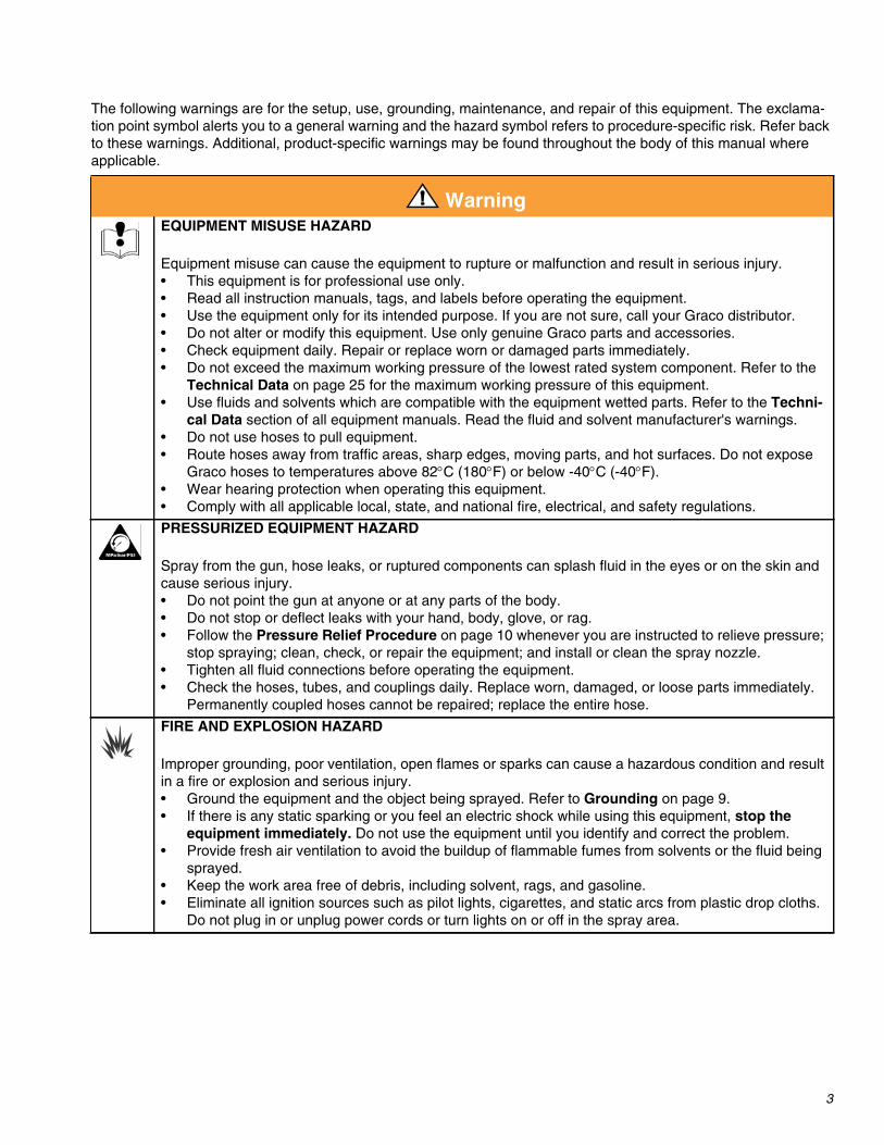
The following warnings are for the setup, use, grounding, maintenance, and repair of this equipment. The exclama-tion point symbol alerts you to a general warning and the hazard symbol refers to procedure-specific risk. Refer backto these warnings. Additional, product-specific warnings may be found throughout the body of this manual whereapplicable.
WarningEQUIPMENT MISUSE HAZARD
Equipment misuse can cause the equipment to rupture or malfunction and result in serious injury.• This equipment is for professional use only.• Read all instruction manuals, tags, and labels before operating the equipment.• Use the equipment only for its intended purpose. If you are not sure, call your Graco distributor.• Do not alter or modify this equipment. Use only genuine Graco parts and accessories.• Check equipment daily. Repair or replace worn or damaged parts immediately.• Do not exceed the maximum working pressure of the lowest rated system component. Refer to the
Technical Data on page 25 for the maximum working pressure of this equipment.• Use fluids and solvents which are compatible with the equipment wetted parts. Refer to the Techni-
cal Data section of all equipment manuals. Read the fluid and solvent manufacturer's warnings.• Do not use hoses to pull equipment.• Route hoses away from traffic areas, sharp edges, moving parts, and hot surfaces. Do not expose
Graco hoses to temperatures above 82°C (180°F) or below -40°C (-40°F).• Wear hearing protection when operating this equipment.• Comply with all applicable local, state, and national fire, electrical, and safety regulations.
PRESSURIZED EQUIPMENT HAZARD
Spray from the gun, hose leaks, or ruptured components can splash fluid in the eyes or on the skin andcause serious injury.• Do not point the gun at anyone or at any parts of the body.• Do not stop or deflect leaks with your hand, body, glove, or rag.• Follow the Pressure Relief Procedure on page 10 whenever you are instructed to relieve pressure;
stop spraying; clean, check, or repair the equipment; and install or clean the spray nozzle.• Tighten all fluid connections before operating the equipment.• Check the hoses, tubes, and couplings daily. Replace worn, damaged, or loose parts immediately.
Permanently coupled hoses cannot be repaired; replace the entire hose.
FIRE AND EXPLOSION HAZARD
Improper grounding, poor ventilation, open flames or sparks can cause a hazardous condition and resultin a fire or explosion and serious injury.• Ground the equipment and the object being sprayed. Refer to Grounding on page 9.• If there is any static sparking or you feel an electric shock while using this equipment, stop the
equipment immediately. Do not use the equipment until you identify and correct the problem.• Provide fresh air ventilation to avoid the buildup of flammable fumes from solvents or the fluid being
sprayed.• Keep the work area free of debris, including solvent, rags, and gasoline.• Eliminate all ignition sources such as pilot lights, cigarettes, and static arcs from plastic drop cloths.
Do not plug in or unplug power cords or turn lights on or off in the spray area.

4
TOXIC FLUID HAZARD
Hazardous fluid or toxic fumes can cause serious injury or death if splashed in the eyes or on the skin,inhaled, or swallowed.• Know the specific hazards of the fluid you are using.• Store hazardous fluid in an approved container. Dispose of hazardous fluid according to all local,
state and national guidelines.• Always wear protective eyewear, gloves, clothing and respirator as recommended by the fluid and
solvent manufacturer.• If a diaphragm fails, fluid is exhausted along with the air. When pumping hazardous fluids, place the
pump in an appropriate container to catch the fluid if a diaphragm ruptures.
MOVING PARTS HAZARD
Moving parts, such as the diaphragm shaft, can pinch or amputate your fingers.• Before servicing the equipment, follow the Pressure Relief Procedure on page 10 to prevent the
equipment from starting unexpectedly.
PERSONAL PROTECTIVE EQUIPMENTYou must wear appropriate protective equipment when operating, servicing, or when in the operatingarea of the equipment to help protect you from serious injury, including eye injury, inhalation of toxicfumes, burns, and hearing loss. This equipment includes but is not limited to:• Protective eyewear• Clothing and respirator as recommended by the fluid and solvent manufacturer• Gloves• Hearing protection
Warning

Installation
5
Installation
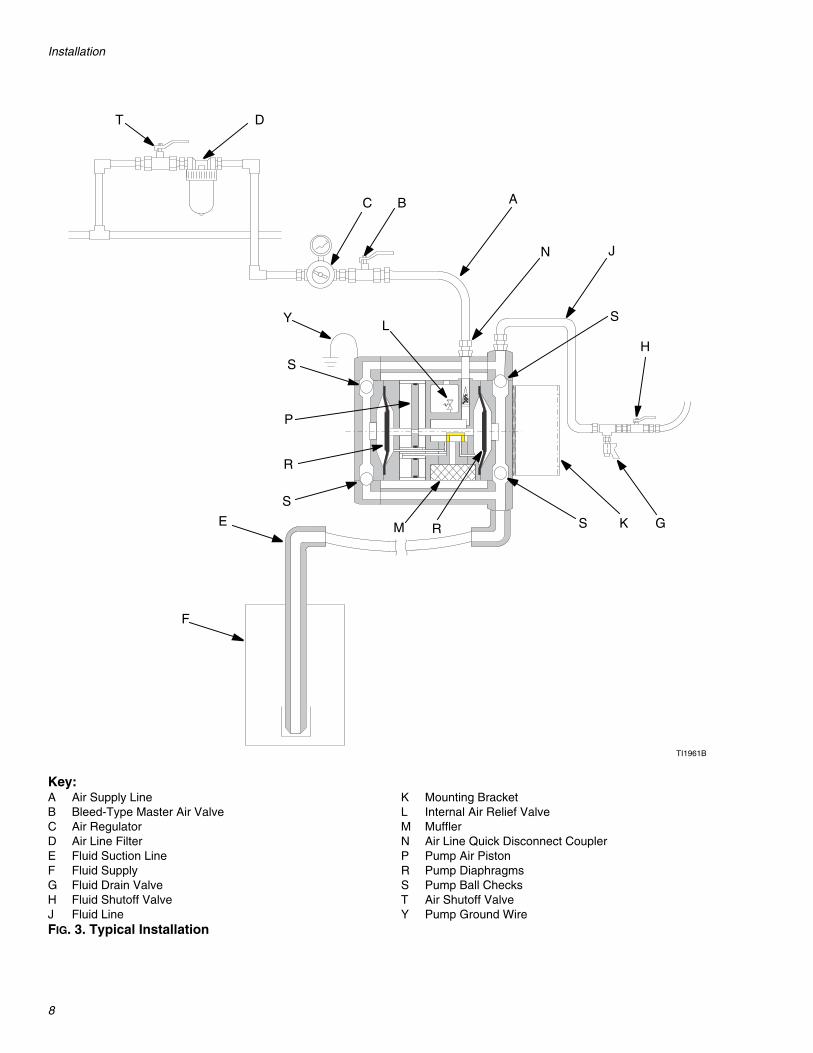
General Information• FIG. 3 on page 8 is only a guide for installing system
components and accessories. It is not an actual sys-tem design. Contact your Graco distributor for assis-tance in designing a system to suit your particularneeds.
• Always use Genuine Graco Parts and Accessories,available from your Graco distributor. If you supplyyour own accessories, be sure they are adequatelysized and pressure-rated for your system.
• Reference numbers and letters in parentheses referto the reference numbers in the figures and theparts list on page 23.
Tighten Threaded Connections1. Before each use, check all hoses for wear or dam-
age and replace as necessary.
2. Check to be sure all threaded connections are tightand leak-free.
3. Check and re-torque all screws and fasteners atleast every two months. Re-torque the fluid coverscrews first, followed by the manifold screws. Note:Before using pump, loosen fluid cover screws (31)1-2 turns and then re-torque to 20 N•m (15 ft-lb).

Installation
6
Mounting the PumpFor ease of operation and service, mount the pump sothe air inlet, fluid inlet, and fluid outlet ports are easilyaccessible. The inlet port must point down and the outletport must point up.
Use 5/8 in. lag screws or bolts for mounting.
Wall Mount Installation
1. Wall Mount Kit 245875 is available. See FIG. 1.
2. Be sure the wall can support the weight of thepump, bracket, hoses and accessories, as well asthe stress caused during operation.
3. Using the wall bracket (B) as a template, drill 5/8 in.mounting holes in the wall. See page 27 for a wallmounting diagram. Mount the bracket 1.2-1.5 m (4-5ft) above the floor.
4. Attach the bracket (B) to the pump (A) with thescrews (C) and washers (D) provided in the kit.
5. Attach the bracket to the wall. Use screws (E) thatare long enough to keep the pump from vibratingduring operation. Be sure the pump is level.
Floor Stand Installation
Floor Stand Kit 245874 is available. See FIG. 2 toassemble.
To ensure proper operation, mount the pump in ahorizontal position.
FIG. 1: Wall Mount Kit
TI2079B
CD
B
A
E
FIG. 2: Floor Stand Installation
TI20798

Installation
7
Air Line1. Install the air line accessories as shown in FIG. 3.
Mount these accessories on the wall or on abracket. Be sure the air line supplying the accesso-ries is grounded.
a. Install an air regulator (C) and gauge to controlthe fluid pressure. The fluid outlet pressure willbe three times the setting of the air regulator.
b. A bleed-type master air valve (B) is required inyour system to relieve air trapped between itand the pump when the valve is closed. Trappedair can cause the pump to cycle unexpectedlywhich could result in serious injury includingsplashing in the eyes or on the skin, or injuryfrom moving parts. Be sure the bleed valve iseasily accessible from the pump, and is locateddownstream from the air regulator.
c. The air line filter (D) removes harmful dirt andmoisture from the compressed air supply.
d. A second bleed-type air valve (T) isolates the airline accessories for servicing. Locate upstreamfrom all other air line accessories.
2. Install a grounded, flexible air hose (A) between theaccessories and the pump air inlet. See TechnicalData on page 25 to determine the air inlet size ofyour pump. Use a minimum 13 mm (1/2 in.) ID airhose.
3. Screw an air line quick disconnect coupler (N) ontothe end of the air hose (A), and screw the mating fit-ting into the pump air inlet snugly. Do not connectthe coupler to the fitting until you are ready to oper-ate the pump.
Fluid Suction Line• Use conductive hoses (E). See FIG. 3.• See Technical Data on page 25 to determine the
fluid inlet size of your pump.• For maximum suction lift (wet and dry) information,
see Technical Data on page 25.
Fluid Outlet Line1. Use conductive fluid hoses (J). See FIG. 3. See
Technical Data on page 25 to determine the fluidoutlet size of your pump.
2. Install a fluid drain valve (G) near the fluid outlet.The fluid drain valve is required to relieve pressurein the hose and gun. The drain valve reduces therisk of serious injury, including splashing in the eyesor on the skin, or injury from toxic fluids.
3. Install a shutoff valve (H) in the fluid outlet line.
Installation
8
Key:A Air Supply LineB Bleed-Type Master Air ValveC Air RegulatorD Air Line FilterE Fluid Suction LineF Fluid SupplyG Fluid Drain ValveH Fluid Shutoff ValveJ Fluid Line
K Mounting BracketL Internal Air Relief ValveM MufflerN Air Line Quick Disconnect CouplerP Pump Air PistonR Pump DiaphragmsS Pump Ball ChecksT Air Shutoff ValveY Pump Ground Wire
FIG. 3. Typical Installation
ABC
D
E
F
G
H
J
K
L
M
N
Y
T
P
R
R S
S
S
S
TI1961B

Installation
9
Grounding
Ground all of this equipment:
• Pump: use a ground wire and clamp. See FIG. 4.Loosen the grounding screw (X). Insert one end of a
1.5 mm2 (12 ga) minimum ground wire (Y) into thepump’s grounding clamp (8) and tighten the screw(X) securely. Connect the other end of the wire to atrue earth ground. For a ground wire and clamp,order Part No. 238909.
• Air and fluid hoses: Use only electrically conductivehoses.
• Air compressor: Follow manufacturer’s recommen-dations.
• Fluid supply drum: Follow your local code.• All solvent pails used when flushing: Follow your
local code. Use only metal pails, which are conduc-tive, placed on a grounded surface. Do not place thepail on a nonconductive surface, such as paper orcardboard, which interrupts the grounding continu-ity.
FIG. 4. Grounding the Pump
Before operating the pump, ground the system asexplained below. Read the warnings on page 3.
Y
X
TI2085A

Operation
10
Operation
Pressure Relief Procedure
1. Shut off the air to the pump.
2. Open the dispensing valve, if used.
3. Open the fluid drain valve to relieve all fluid pres-sure, having a container ready to catch the drain-age.
Flush the Pump Before First UseThe pump was tested in oil. If the oil could contaminatethe fluid you are pumping, flush the pump thoroughlywith a compatible solvent. Follow the steps under Start-ing and Adjusting the Pump.
Starting and Adjusting the Pump1. Be sure the pump is properly grounded. Refer to
Grounding on page 9.
2. Check all fittings to be sure they are tight. Be sure touse a compatible liquid thread sealant on all malethreads.
3. Re-torque all screws and fasteners before startup.Re-torque the fluid cover screws first, followed bythe manifold screws.
4. Place the suction tube (E) in the fluid to be pumped.
5. Place the end of the fluid hose (J), see FIG. 3, intoan appropriate container.
6. Close the fluid drain valve (G). Open the fluid shutoffvalve (H).
7. With the pump air regulator (C) closed, open thebleed-type master air valve (B).
8. If the fluid hose has a dispensing device, hold itopen while continuing with the following step.
9. Slowly open the air regulator (C) until the pumpstarts to cycle. Allow the pump to cycle slowly untilall air is pushed out of the lines and the pump isprimed.
If you are flushing, run the pump long enough to thor-oughly clean the pump and hoses. Close the air regula-tor. Remove the suction tube (E) from solvent and placeit in the fluid to be pumped.
Pump Shutdown
Short Term Shutdown
For a short term shutdown, relieve the pressure (see atleft).
Long Term Shutdown
For a long term shutdown, such as several hours orovernight:
1. Flush the pump thoroughly.
2. Leave compatible solvent in the pump.
3. Relieve the pressure (see at left).
Read the warnings on page 3, and follow the Pres-sure Relief procedure below whenever you:
• are instructed to relieve pressure• stop spraying• check or service any of the equipment• install or clean the fluid nozzle.
Operating the pump beyond the maximum airinput pressure will decrease diaphragm life.
Do not operate the pump dry for long periods oftime to avoid reducing diaphragm life.

Maintenance
11
Maintenance
Lubrication
Flushing and StorageFlush the pump with a compatible solvent often enoughto prevent the fluid you are pumping from drying in thepump and damaging it. Follow the Pressure Relief Pro-cedure on page 10 before storing it for any length oftime.
Tighten Threaded Connections1. Before each use, check all hoses for wear or dam-
age, and replace as necessary.
2. Check to be sure all threaded connections are tightand leak-free.
3. Check and re-torque all screws and fasteners atleast every two months. Re-torque the fluid coverscrews first, followed by the manifold screws.NOTE: Before using pump, loosen fluid coverscrews (31) 1-2 turns and then re-torque to 20 N•m(15 ft-lb).
Preventive MaintenanceScheduleEstablish a preventive maintenance schedule, based onthe service history of the pump. This is especially impor-tant for prevention of spills or leakage due to diaphragmfailure.
CAUTION
Lubrication of the pump is not required. Oil isexhausted through the muffler, which could contami-nate the fluid supply or other equipment. Excessivelubrication can also cause the pump to malfunction.

Troubleshooting
12
TroubleshootingRelieve the pressure (page 10) before checking orservicing the equipment.
Check all possible problems and causes beforedisassembling the pump.
Problem Cause Solution
Pump cycles at stall or fails to holdpressure at stall.
Worn check valve balls (56), seats(53), or ball guides (57).
Replace. See page 19.
Pump will not cycle, or cycles onceand stops.
Stuck or dirty air valve. Disassemble and clean air valve. Seepage 17. Use filtered air.
Check valve ball (56) severely wornand wedged in seat (53).
Replace ball and seat. See page 19.
Check valve ball (56) wedged in seat(53) due to overpressurization.
Replace. See page 19. Do notexceed the maximum fluid workingpressure, see page 25.
Clogged fluid dispensing valve. Relieve pressure and clear valve.
Pinched hose line. Check lines.
Pump operates erratically. Clogged suction line. Inspect; clear.
Sticky or leaking check valves. Clean or replace balls (56) and seats(53). See page 19.
Ruptured diaphragm (14). Replace. See page 15. Do notexceed maximum air input pressure.
Restricted exhaust. Remove restriction.
Air bubbles in fluid. Loose suction line. Tighten.
Ruptured diaphragm (14). Replace. See page 15.
Pump running irregularly. Stroke fre-quency dropping, coming to stand-still.
Worn parts. Replace worn parts. Check com-pressed air supply.
Icing caused by: compressed air toomoist, stroke frequency too high,local temperature too low.
Remove ice by changing operatingconditions.
Air escapes continually from muffler. Damaged air valve cup (47) or seat(33).
Replace damaged parts. See page17.
Foreign matter inside pump. Check air filter.
Pump does not start, or pressurefluctuates.
Worn check valve seats (53). Replace. See page 19.
Inlet strainer blocked, maximum suc-tion exceeded, hose or seal defec-tive.
Clean strainer. Replace defectiveparts.
Contaminated fluid. Pump installed oroperated incorrectly.
Check fluid supply. Follow installa-tion and operation instructions in thismanual.
Troubleshooting
13
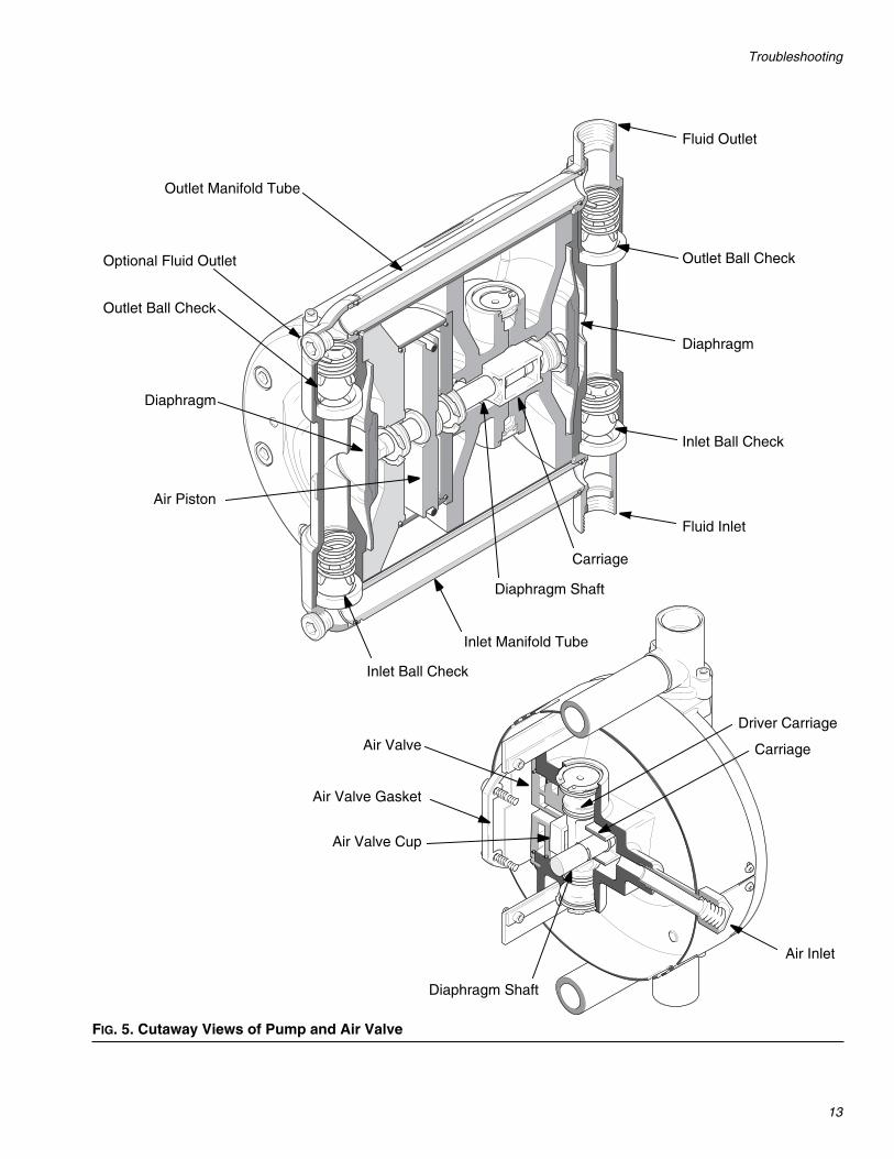
FIG. 5. Cutaway Views of Pump and Air Valve
Fluid Outlet
Outlet Ball Check
Diaphragm
Air Piston
Inlet Ball Check
Outlet Manifold Tube
Fluid Inlet
Inlet Manifold Tube
Outlet Ball Check
Diaphragm
Inlet Ball Check
Diaphragm Shaft
Optional Fluid Outlet
Air Valve
Air Valve Gasket
Diaphragm Shaft
Air Valve Cup
Carriage
Driver Carriage
Air Inlet
Carriage
Repair
14
Repair
Prepare the Pump for Repair1. Flush the pump if possible, page 11.
2. Relieve the pressure, page 10.
3. Disconnect the air and fluid hoses.
4. Remove the pump from its mounting and take it tothe work bench.
General Repair Notes
Fault IndicationsDuring operation, check for indications of worn or dam-aged parts, such as:
• major pressure fluctuations• change in the pump’s operating sound• irregular operation.
Always replace worn or damaged parts immediately toprevent additional damage.
Tools Required• 4, 5, 6, 8 and 10 mm allen wrenches• 13 mm open end wrench• 28 mm open end wrench, or adjustable wrench• two flat blade screwdrivers• #2 Phillips screwdriver• internal snap ring pliers• dowel rod (wood or plastic)• o-ring pick• diaphragm installation tool (part number 261695)
• A qualified technician should make all repairs.• Inspect and clean all parts thoroughly before
reassembly.• Use only genuine Graco replacement parts,
available from your Graco distributor.• Be careful not to damage sealing surfaces.• Replace all o-rings removed from the pump.• Follow all lubrication, torque, and repair notes
in the repair procedures.• Do not use silicone or silicone-based grease.

Repair
15
Replace the Diaphragms
Disassembly
1. Prepare the pump for repair, page 14.
2. Remove the screws (31) from one fluid cover (1).Pull the cover assembly off, separating it from thefluid tubes (12). See FIG. 6.
3. Remove the fluid tubes (12) from the other coverassembly.
4. Remove the screws (31) and the remaining fluidcover (1).
5. Install diaphragm (14) using the diaphragm repairtool to force the shaft all the way to one side. Pressthe short, wide boss on the tool directly on the dia-phragm. The part number on the tool should faceaway from the pump. See FIG. 6.
6. Unscrew the opposite diaphragm (14) from the shaftby turning it counterclockwise by hand.
7. Push the shaft in the opposite direction by installingthe diaphragm repair tool on the opposite side of thepump. Press the tall boss on the tool directly on thepump shaft. The part number on the tool shouldface toward the pump. See FIG. 6.
8. Unscrew the remaining diaphragm (14) from theshaft by turning it counterclockwise by hand.
Reassembly
1. While the diaphragm repair tool holds the shaft toone side, screw the new diaphragm (14*) into theshaft by hand. See FIG. 6.
2. Depress the first diaphragm (14*) using the dia-phragm repair tool and install the opposite dia-phragm (14*) by hand.
3. Remove the o-rings (13) from the fluid tubes (12)and replace with new o-rings (13*) from the kit.
4. Install the cover assembly that has the tube hous-ings (4) attached. The arrow must point toward thetop of the pump and the air inlet (40) must be to theright of the cover (1). Torque the screws (31) to 20N•m (15 ft-lb).
5. Lubricate the o-rings (13*) and ends of the fluidtubes (12) and push the tubes into the tube hous-ings (4) so they are securely seated.
6. Install the cover assembly that has the fluid inlet (3)and outlet (2) housings attached. The arrow mustpoint toward the top of the pump. Seat the coversecurely on the fluid tubes (12). Torque the screws(31) oppositely and evenly to 20 N•m (15 ft-lb).
Diaphragm Repair Kit 243152 is available. Partsincluded in the kit are marked, for example (14*).For the best results, replace both diaphragms andall o-rings (13*).
Diaphragm Repair Tool 261695 is available toassist with diaphragm installation.
Operating the pump beyond the maximum airinput pressure will decrease diaphragm life.
Do not operate the pump dry for long periods oftime to avoid reducing diaphragm life.

Repair
16
FIG. 6. Replace the Diaphragms
13*
1213*
14*
13*
12
13*
14*
31
31
1
40
1
2
3
Lubricate.
Torque to 20 N•m (15 ft-lb)
1
2
21
1
1
1
2
TI1959A
4
4
TI8632A
TI8633A
Diaphragm Repair Tool 261695

Repair
17
Repair the Air Valve
Disassembly
1. Prepare the pump for repair, page 14.
2. Remove the screws (31) from one fluid cover (1).Pull the cover assembly off, separating it from thefluid tubes (12). See FIG. 7.
3. Remove the screws (31) and the other fluid cover(1) assembly, keeping the fluid tubes (12) attached.
4. Remove the air inlet fitting (40).
5. Remove the screws (68) and the top (67) and bot-tom (66) covers.
6. Remove the diaphragms (14), page 15.
7. Remove the four screws (38) and washers (37), airvalve cover (36), and gasket (35).
8. Pry the air valve seat (33) out of the housing (5),using two screwdrivers inserted in the recesses onthe seat. Remove the o-rings (43, 44, and 80) fromthe seat.
9. Remove the cup (47) from the center housing.
10. Remove the two clips (46) from the shaft (17).
11. Remove the screws (30), cylinder outer cover (11),and cylinder (7). Do not lose the o-rings (22).
12. Pull out the piston (16) and shaft assembly.
13. Remove the screws (29) and inner cover (6).
14. Remove the clips (50) from the air valve plugs (51).Thread a screw (38) partially into each plug and pullthe plugs out. Remove the o-rings (52).
15. Push the driver carriage (48) out of its bore.Remove the o-rings (49).
16. Remove the clips (21) and push the bearings (18)out of the center housing (5), inner cover (6), andouter cover (11). Remove the o-rings (19, 20) fromthe bearings.
17. Remove the carriage (45).
Reassembly
1. Install the o-rings (19†, 20†) on the three bearings(18). Install the bearings in the center housing (5),cylinder inner cover (6), and cylinder outer cover(11). Secure with the clips (21).
2. Install the carriage (45) in the center housing (5),oriented as shown.
3. Install the o-rings (49†) on the driver carriage(48†).Push the driver carriage into its bore, orientedas shown.
4. Install the o-rings (52†) on the air valve plugs (51).Install the plugs and secure with clips (50).
5. Check that the o-rings (42 and 28) are in place inthe center housing (5).
6. Check that the o-rings (22 and 25) are in place onthe cylinder inner cover (6).
7. Check that the o-ring (23), packing (26), and quadring (32) are in place on the piston (16).
8. Insert the air valve tube (24) through the cylinderinner cover (6). Install the cover on the center hous-ing (5). Seat the air valve tube securely in the centerhousing, oriented with the spring pin (27). Torquethe screws (29) to 8 N•m (5.9 ft-lb).
9. Lubricate the diaphragm shaft (17), then slide it intothe center housing (5), guiding the air valve tube(24) through the hole in the piston. Install the twoclips (46) on the shaft.
10. Liberally grease the inside of the cylinder (7) andthe piston o-ring (23). Install the cylinder, makingsure it is seated on the inner cover (6).
11. Install the o-ring (22) on the cylinder outer cover(11). Install the outer cover. Torque the screws (30)to 15 N•m (11 ft-lb).
Air Valve Repair Kit 243153 is available. Partsincluded in the kit are marked, for example (33†).For the best results, use all parts in the kit.
Lubricate all o-rings when reassembling thepump.

Repair
18
12. Install the cup (47†) in the center housing.
13. Install the o-rings (43†, 44†, and 80†) on the airvalve seat (33†). Lubricate the o-rings. Install theseat in the center housing (5), oriented with thespring pin (34).
14. Install the gasket (35†), cover (36), and screws andwashers (38, 37). Torque to 6 N•m (4.4 ft-lb).
15. Reinstall the diaphragms (14), page 15.
16. Install the fluid covers (1). The arrows must point up.Torque the screws (31) to 20 N•m (15 ft-lb).
17. Check that the felt strips (71) are in place on theinside of the top (67) and bottom (66) covers. Installthe covers. The hole for the air inlet fitting must alignwith the port in the center housing (5). Tighten thescrews (68).
18. Install the air inlet fitting (40).
FIG. 7. Repair the Air Valve
3837
3635†
†33
†43†44
†47 45
67
5
31
12
68
66
68
7
22
22
11
20†18
19†
2114
31
21 19†18 20†
29
30
17
46
28
625
2442
†52
50
40
26
32
2119†18
20†
48†
†49†52
5150
14
15 23
51
1
2
3
4
5
5
1
1
1
1
1
1
1
11
TI1958B
27
34
1
1
71
71
16
Lubricate.
Torque to 8 N•m (5.9 ft-lb)
Torque to 15 N•m (11 ft-lb)
Torque to 6 N•m (4.4 ft-lb)
Torque to 20 N•m (15 ft-lb)
1
2
3
4
5
12†801

Repair
19
Replace the Ball Check Valves
Disassembly
1. Prepare the pump for repair, page 14.
2. Remove the screws (38) and take the tube assem-blies off the pump. See FIG. 8.
3. Remove the springs (65), ball guides (57), and balls(56) from the outlet (top) check valves.
4. Insert a dowel through the outlet seats (53) andpush the inlet (bottom) valve parts (65, 57, 56, 53,58) out of the pump. Remove the flat seal (59).
5. Insert a dowel through the inlet ports and push theoutlet valve seats (53) and sleeves (54) out of thepump. Remove the flat seals (55, 59).
Reassembly
1. Install the outlet check valves into the fluid covers(1): a flat seal (59★), seat (53‡), seal (59★), sleeve(54), ball (56‡), ball guide (57‡), spring (65‡), andseal (55★).
2. Install the outlet tube assembly. Torque the screws(38) to 10 N•m (7.4 ft-lb).
3. Install the inlet check valves into the fluid covers (1):a spring (65‡), ball guide (57‡), ball (56‡), seat(53‡), flat seal (59★), and seal (58).
4. Install the inlet tube assembly. Torque the screws(38) to 10 N•m (7.4 ft-lb).
Ball Check Valve Repair Kit 243154 is available.Parts included in the kit are marked, for example(56‡). For the best results, use all parts in the kit.
Sealing Ring Repair Kit 243156 is available. Partsincluded in the kit are marked, for example (55★).For the best results, use all parts in the kit.
If the ball is stuck in the seat, pry it loose with ascrewdriver.
Some parts will be reused, so be careful not todrop or lose parts.
CAUTION
The outlet ball check valves must be installed exactlyas shown in FIG. 8:
• beveled side of seat (53) must face the ball (56)• beveled end of sleeve (54) must face the seat (53)• open end of ball guide (57) must face the ball (56)• turned down end of spring (65) must face the ball
guide (57)
CAUTION
The inlet ball check valves must be installed exactlyas shown in FIG. 8:
• turned down end of spring (65) must face the ballguide (57)
• open end of ball guide (57) must face the ball (56)• beveled side of seat (53) must face the ball (56)• wide end of seal (58) must face the seat (53)

Repair
20
FIG. 8. Replace the Ball Check Valves
12
38
2
65‡
57‡
56‡
55★
54
59★
53‡
65‡
57‡
56‡
53‡
59★
58
3
38124
38
58
‡53
‡56
‡57
‡65
★59
‡65
‡57
‡56
★55
54
38
4
59★
‡53
★59
★59
Torque to 10 N•m (7.4 ft-lb)1 1
1
1
1
TI1960A
1
1
Repair
21
Replace the Cylinder and PistonSeals
Disassembly
1. Prepare the pump for repair, page 14.
2. Remove the screws (38) and tube assemblies. SeeFIG. 9.
3. Disassemble the ball check valves, page 19. The flatseals (55, 59) are included with this repair kit.
4. Remove the air inlet fitting (40).
5. Remove the screws (68) and the top (67) and bot-tom (66) covers.
6. Remove the screws (31) and fluid covers (1).
7. Remove the diaphragms (14), page 15.
8. Remove the four screws (38) and washers (37), theair valve cover (36), and the gasket (35).
9. Pry the air valve seat (33) out of the center housing(5), using two screwdrivers inserted in the recesseson the seat.
10. Remove the o-rings (80) from the housing.
11. Remove the cup (47) from the housing.
12. Remove the two clips (46) from the shaft (17).
13. Remove the screws (30), cylinder outer cover (11),cylinder (7), and cylinder o-rings (22). Inspect theinner wall of the cylinder for damage.
14. Pull the piston (16) and shaft out of the center hous-ing (5). Remove the piston o-ring (23), quad ring(32), and packing (26). Inspect the piston and shaftfor damage. If these parts need replacement,unscrew the piston shaft (15) from the diaphragmshaft (17) and remove the piston (16).
15. Remove the screws (29) and cylinder inner cover(6). Remove the air valve tube (24) and o-ring (25)from the inner cover. Do not lose the o-ring (25).
16. Remove the o-rings (28, 42) from the center hous-ing (5). Do not lose the o-ring (28).
Reassembly
1. Install the o-rings (42◆, 28) in the housing (5).
2. Install the o-rings (22◆, 25) on the inner cover (6).
3. Install the o-ring (23◆), packing (26◆), and quadring (32◆) on the piston (16).
4. Insert the air valve tube (24) through the inner cover(6). Install the cover on the housing (5). Seat thetube securely in the housing, oriented with thespring pin (27). Torque the screws (29) to 8 N•m (5.9ft-lb).
5. If the piston (16) was removed from the piston shaft(15), reassemble a washer (61), the piston, andanother washer on the shaft. Screw the diaphragmshaft (17) onto the piston shaft.
6. Lubricate the shaft (17) and slide it into the housing(5), guiding the tube (24) through the hole in the pis-ton. Install the two clips (46) on the shaft.
7. Liberally grease the inside of the cylinder (7) andthe piston o-ring (23◆). Seat the cylinder securelyon the inner cover (6).
8. Install the o-ring (22◆) on the outer cover (11).Install the outer cover and torque the screws (30) to15 N•m (11 ft-lb).
9. Install the cup (47) in the center housing (5).
10. Install the o-rings (80). Check that the o-rings (43,44) are in place on the air valve seat (33). Lubricatethe o-rings. Install the seat in the center housing (5),oriented with the spring pin (34).
11. Install the gasket (35), cover (36), and screws andwashers (38, 37). Torque to 6 N•m (4.4 ft-lb).
Cylinder Seal Repair Kit 243155 is available.Parts included in the kit are marked, for example(22◆). For the best results, use all parts in the kit.
To further disassemble and repair the air valve,see page 17.
Lubricate all o-rings during reassembly.

Repair
22
12. Install the diaphragms (14), page 15.
13. Install the fluid covers (1). The arrows must point up.Torque the screws (31) to 20 N•m (15 ft-lb).
14. Check that the felt strips (71) are in place on theinside of the top (67) and bottom (66) covers. Installthe covers. The hole for the air inlet fitting must alignwith the port in the center housing (5). Tighten thescrews (68).
15. Install the air inlet fitting (40).
16. Install the flat seals (55◆, 59◆) and the other ballcheck parts, see page 19.
17. Install the tube assemblies. Torque the screws (38)to 10 N•m (7.4 ft-lb).
FIG. 9. Replace the Cylinder and Piston Seals
3837
3635
33
67
5
1238
65
57
56
55◆★
54
59◆★
53
1
31
65
57
56
53
59◆★
58
38
12
68
66
68
722◆
22◆
14
5859◆★
53
56
57
65
31
1
★◆59
65
5756
★◆5554
53
29
30
17
46
28
625
2442◆
51
50
40
◆26
32◆
48
5150
14
15
1623◆
11
Lubricate.
Torque to 8 N•m (5.9 ft-lb)
Torque to 15 N•m (11 ft-lb)
Torque to 6 N•m (4.4 ft-lb)
Torque to 20 N•m (15 ft-lb)
Torque to 10 N•m (7.4 ft-lb)
1
2
3
4
5
6
2
3
4
5
1
6
1
1
1
1
1
1
1
56
TI2074B
34
27 6161
4344
71
71
80
47

Parts
23
Parts
Part No. 253707 includes items 1-81Part No. 253708 includes items 1-8,10-59, 61-81
38 37 36 35†
†33
†43
†44 †4745
67
5
13*
12
13*38
265‡
57‡56‡
55◆★
5459◆★
‡53
131
65‡
57‡
56‡
53‡59◆★
58
3
3813*12
13*
6866
687
22◆
22◆
1120†
1819†
2114*
4
38109
5859◆★
‡53‡56‡57
‡65
31
1
★◆59
‡65
‡57
‡56★◆55
54
53‡
2119†
18 20†29
30
17
46
28
625
2442◆
38
48
9
10
†5251
50
39
40
◆26
32◆
6463
62
2119†18
20†
48†
†49
†525150
14*
15
61 16
23◆61
TI1957B
27
34
60
60
71
71
80
81

Parts
24
Part No. 253707 includes items 1-81Part No. 253708 includes items 1-8,10-59, 61-81
* Included in Diaphragm Repair Kit 243152.1
† Included in Air Valve Repair Kit 243153.
‡ Included in Ball Check Valve Repair Kit 243154.
◆ Included in Cylinder Seal Repair Kit 243155.
★ Included in Sealing Ring Repair Kit 243156.
NOTE: ▲ Replacement Warning labels, signs, tags,and cards are available at no cost.
Ref.No.
Part No. Description Qty
1 15A010 COVER, fluid 22 15A000 HOUSING, outlet, fluid; for 253707 1
15A003 HOUSING, outlet, fluid; for 253708 13 15A002 HOUSING, inlet, fluid; for 253707 1
15A003 HOUSING, inlet, fluid; for 253708 14 15A001 HOUSING, tube, fluid; for 253707 2
15A004 HOUSING, tube, fluid; for 253708 25 15A032 HOUSING, center 16 15A051 COVER, inner, cylinder 17 15A050 CYLINDER 18 116343 CLAMP, grounding 19 116898 WASHER; for 253707 only 210 116902 PLUG, socket-hd; for 253707 2
112306 PLUG, pipe; for 253708 211 15A052 COVER, outer, cylinder 112 15A037 TUBE, fluid 213* O-RING; chemically resistant
fluoroelastomer4
14* DIAPHRAGM; PTFE 215 15A042 SHAFT, piston 116 15A038 PISTON 117 15A043 SHAFT, diaphragm 118 15A006 BEARING 319† O-RING; fluoroelastomer 320† O-RING; nitrile 321 117021 CLIP, c-spring 322◆ O-RING; nitrile 223◆ O-RING; nitrile 124 15A031 TUBE, air valve 125 117006 O-RING; nitrile 126◆ PACKING, PTFE 127 117023 PIN, spring 128 117012 O-RING; fluoroelastomer 229 117028 SCREW, socket-hd; M6 x 16 430 117034 SCREW, socket-hd; M8 x 100 431 116900 SCREW, cap, socket-hd; M10 x 25 1632◆ RING, quad; nitrile 133† SEAT, air valve 134 117024 PIN, spring 135† GASKET 136 15A035 COVER, air valve 137 117018 WASHER 4
38 117029 SCREW, cap, socket-hd; M6 x 25 1239 117019 VALVE, safety, relief 140 15A790 FITTING, inlet, air; for 253707 1
15A044 FITTING, inlet, air; for 253708 142◆ O-RING; nitrile 143† O-RING; nitrile 144† O-RING; nitrile 245 15A033 CARRIAGE 146 117022 CLIP, c-spring 247† CUP, air valve 148† CARRIAGE, driver 149† O-RING; nitrile 250 117020 CLIP, c-spring 251 15A009 PLUG, air valve 252† O-RING; nitrile 253‡ SEAT, valve 454 15A026 SLEEVE, ball guide 255◆★ SEAL, flat; UHMWPE 256‡ BALL, 30 mm; acetal 457‡ GUIDE, ball 458 15A036 SEAL; acetal homopolymer 259◆★ SEAL, flat; UHMWPE 660 15A005 BUSHING; for 253707 only 261 15A482 WASHER 262 15A016 DAMPENER, noise 263 15A028 PLATE 264 117026 SCREW, cap, socket-hd; M5 x 12 465‡ SPRING, compression 466 15J373 COVER, bottom 167 15J375 COVER, top 168 116595 SCREW; M4 x 0.7 870▲ 188621 LABEL, warning (not shown) 171 15A008 DAMPENER, felt 280† 158486 O-ring, nitrile 281 111307 WASHER 1
Ref.No.
Part No. Description Qty
Technical Data
25
Technical Data
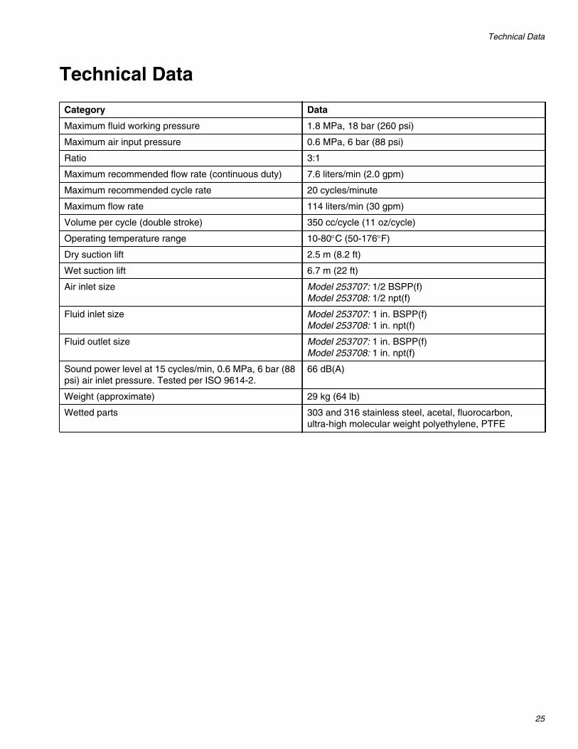
Category Data
Maximum fluid working pressure 1.8 MPa, 18 bar (260 psi)
Maximum air input pressure 0.6 MPa, 6 bar (88 psi)
Ratio 3:1
Maximum recommended flow rate (continuous duty) 7.6 liters/min (2.0 gpm)
Maximum recommended cycle rate 20 cycles/minute
Maximum flow rate 114 liters/min (30 gpm)
Volume per cycle (double stroke) 350 cc/cycle (11 oz/cycle)
Operating temperature range 10-80°C (50-176°F)
Dry suction lift 2.5 m (8.2 ft)
Wet suction lift 6.7 m (22 ft)
Air inlet size Model 253707: 1/2 BSPP(f)Model 253708: 1/2 npt(f)
Fluid inlet size Model 253707: 1 in. BSPP(f)Model 253708: 1 in. npt(f)
Fluid outlet size Model 253707: 1 in. BSPP(f)Model 253708: 1 in. npt(f)
Sound power level at 15 cycles/min, 0.6 MPa, 6 bar (88psi) air inlet pressure. Tested per ISO 9614-2.
66 dB(A)
Weight (approximate) 29 kg (64 lb)
Wetted parts 303 and 316 stainless steel, acetal, fluorocarbon,ultra-high molecular weight polyethylene, PTFE

Performance Charts
26
Performance Charts
CYCLES PER MINUTE
AIR
CO
NS
UM
PT
ION
m3 /
min
(scf
m)
FL
UID
OU
TL
ET
PR
ES
SU
RE
MP
a,b
ar(p
si)
FLUID FLOW lpm (gpm); tested in No. 10 weight oil
(280)
(240)
(200)
(160)
(120)
(80)
(40)
0
1.9, 19
1.7, 17
1.4, 14
1.0, 11
0.8, 8
0.6, 5.5
0.3, 2.8
22 43 65 87 109 130 152 174 196 217 2390
(42)
(35)
(28)
(21)
(14)
(7)
0
1.2
1.0
0.8
0.6
0.4
0.2
7.6 15.1 22.7 30.2 37.8 45.4 52.9 60.5 68.0 75.6 83.2
Key
A = 0.6 MPa, 6 bar (88 psi)
B = 0.4 MPa, 4 bar (60 psi)
C = 0.2 MPa, 2 bar (30 psi)
= Fluid Flow
= Air Consumption
A
B
CC
B
A
(2) (4) (6) (8) (10) (12) (14) (16) (18) (20) (22)
FL
UID
OU
TL
ET
PR
ES
SU
RE
MP
a,b
ar(p
si)
FLUID FLOW lpm (gpm); tested in No. 10 weight oil
7.6 15.13.81.9 5.7 9.5 11.4 13.3
CYCLES PER MINUTE225 11 16 27 33 38 430
Recommended Performance for Continuous Duty
C
B
A
(2.0) (4.0)(1.0)(0.5) (1.5) (2.5) (3.0) (3.5)
1.9, 19
1.7, 17
1.4, 14
1.0, 11
0.8, 8
0.6, 5.5
0.3, 2.8
(280)
(240)
(200)
(160)
(120)
(80)
(40)
Dimensions
27
Dimensions
Wall Mount Hole PatternFor Accessory Wall Mount Kit 245875
Torque Sequence
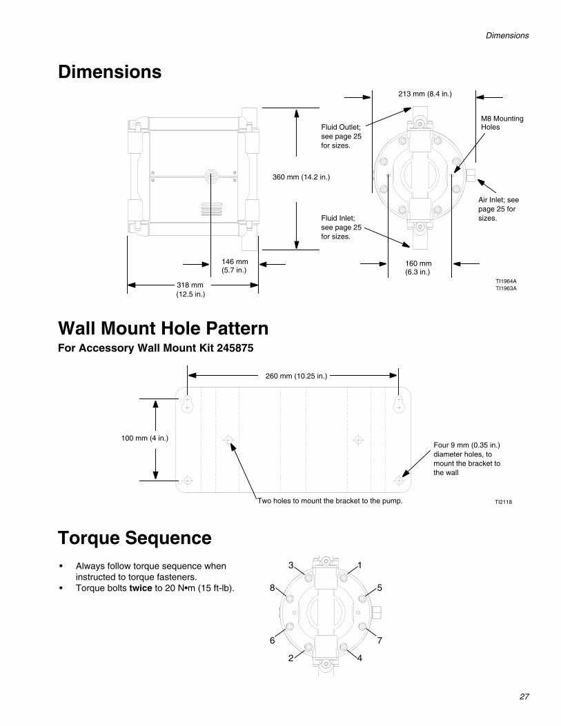
360 mm (14.2 in.)
318 mm(12.5 in.)
146 mm(5.7 in.)
160 mm(6.3 in.)
213 mm (8.4 in.)
M8 MountingHoles
Air Inlet; seepage 25 forsizes.Fluid Inlet;
see page 25for sizes.
Fluid Outlet;see page 25for sizes.
TI1964ATI1963A
100 mm (4 in.)
260 mm (10.25 in.)
TI2118
Four 9 mm (0.35 in.)diameter holes, tomount the bracket tothe wall
Two holes to mount the bracket to the pump.
1
2
3
4
5
6 7
8
• Always follow torque sequence wheninstructed to torque fasteners.
• Torque bolts twice to 20 N•m (15 ft-lb).
All written and visual data contained in this document reflects the latest product information available at the time of publication.Graco reserves the right to make changes at any time without notice.
This manual contains English. MM 311689
Graco Headquarters: MinneapolisInternational Offices: Belgium, China, Japan, Korea
GRACO INC. P.O. BOX 1441 MINNEAPOLIS, MN 55440-1441Copyright 2006, Graco Inc. is registered to ISO 9001
www.graco.comRevised 09/2009
Graco Standard WarrantyGraco warrants all equipment referenced in this document which is manufactured by Graco and bearing its name to be free from defects inmaterial and workmanship on the date of sale to the original purchaser for use. With the exception of any special, extended, or limited warrantypublished by Graco, Graco will, for a period of twelve months from the date of sale, repair or replace any part of the equipment determined byGraco to be defective. This warranty applies only when the equipment is installed, operated and maintained in accordance with Graco’s writtenrecommendations.
This warranty does not cover, and Graco shall not be liable for general wear and tear, or any malfunction, damage or wear caused by faultyinstallation, misapplication, abrasion, corrosion, inadequate or improper maintenance, negligence, accident, tampering, or substitution ofnon-Graco component parts. Nor shall Graco be liable for malfunction, damage or wear caused by the incompatibility of Graco equipment withstructures, accessories, equipment or materials not supplied by Graco, or the improper design, manufacture, installation, operation ormaintenance of structures, accessories, equipment or materials not supplied by Graco.
This warranty is conditioned upon the prepaid return of the equipment claimed to be defective to an authorized Graco distributor for verification ofthe claimed defect. If the claimed defect is verified, Graco will repair or replace free of charge any defective parts. The equipment will be returnedto the original purchaser transportation prepaid. If inspection of the equipment does not disclose any defect in material or workmanship, repairs willbe made at a reasonable charge, which charges may include the costs of parts, labor, and transportation.
THIS WARRANTY IS EXCLUSIVE, AND IS IN LIEU OF ANY OTHER WARRANTIES, EXPRESS OR IMPLIED, INCLUDING BUT NOT LIMITEDTO WARRANTY OF MERCHANTABILITY OR WARRANTY OF FITNESS FOR A PARTICULAR PURPOSE.
Graco’s sole obligation and buyer’s sole remedy for any breach of warranty shall be as set forth above. The buyer agrees that no other remedy(including, but not limited to, incidental or consequential damages for lost profits, lost sales, injury to person or property, or any other incidental orconsequential loss) shall be available. Any action for breach of warranty must be brought within two (2) years of the date of sale.
GRACO MAKES NO WARRANTY, AND DISCLAIMS ALL IMPLIED WARRANTIES OF MERCHANTABILITY AND FITNESS FOR APARTICULAR PURPOSE, IN CONNECTION WITH ACCESSORIES, EQUIPMENT, MATERIALS OR COMPONENTS SOLD BUT NOTMANUFACTURED BY GRACO. These items sold, but not manufactured by Graco (such as electric motors, switches, hose, etc.), are subject tothe warranty, if any, of their manufacturer. Graco will provide purchaser with reasonable assistance in making any claim for breach of thesewarranties.
In no event will Graco be liable for indirect, incidental, special or consequential damages resulting from Graco supplying equipment hereunder, orthe furnishing, performance, or use of any products or other goods sold hereto, whether due to a breach of contract, breach of warranty, thenegligence of Graco, or otherwise.
FOR GRACO CANADA CUSTOMERSThe Parties acknowledge that they have required that the present document, as well as all documents, notices and legal proceedings entered into,given or instituted pursuant hereto or relating directly or indirectly hereto, be drawn up in English. Les parties reconnaissent avoir convenu que larédaction du présente document sera en Anglais, ainsi que tous documents, avis et procédures judiciaires exécutés, donnés ou intentés, à la suitede ou en rapport, directement ou indirectement, avec les procédures concernées.
Graco InformationFor the latest information about Graco products, visit www.graco.com.
TO PLACE AN ORDER, contact your Graco distributor, or call this number to identify the distributor closest to you:
1-800-328-0211 Toll Free612-623-6921
612-378-3505 Fax