triple offset metal seated butterfly valves - :::sw valve ::: · · 2012-11-06triple offset metal...
TRANSCRIPT

Triple Offset Metal Seated Butterfly Valves
100% Bi-directional tight shut off at full rated pressure.
Figure Number AbbreviationTOW Series Triple Offset wafer type metal seated butterfly valve
TOL Series Triple Offset lug type metal seated butterfly valves
TOF Series Triple Offset flange type metal seated butterfly valves
Standard ComplianceConform to API 609, ISO 5752, BS 5155, and MSS SP 67
Firesafe requirement meets BS 6755 part 2 / API6FA and API Std 607 4th edition.
Production RangeSIZE : 50mm(2inch) ~ 2000mm(80inch)
Working Pressure : Maximum 2220psi (156 / )
(Standard) upto 25 bar for DN 80 ~ DN 600
upto 16 bar for DN 650 ~ DN 1000
upto 10 bar for DN 1200 ~ DN 2000
Working Temperature : -29 ~ +538 (Standard)
-100 ~ +700 (Seleciton Meterial)
Connection FlangeBS4504 PN10, PN16, PN25 and PN40 / DIN2501 PN10, PN16, PN25 and PN40 /
ANSI B16.5, 16.47 / 150LB, 300LB, 600LB and 900LB / MSS SP44 CL / 150LB,
300LB, 600LB, 900LB
ISO 2531 PN10, PN16, PN25 and PN40 / KS/JIS 10K, 16K & 20K / 30K / 40K
Face to Face DimensionsConform to API609, BS 5155, ISO 5752 and ANSI B 16.34
ApplicationNuclear power Plants Petrochemical plants
Petroleum refinery Fossil power plants
Fire safe line Exhaust gas line & Steam line
Cryogenic services

Ti
lO
fftM
tlS
td
Btt
flV
l
23Triple Offset Metal Seated Butterfly Valves
Triple Offset Metal Seated Butterfly Valves
Design Features
Construction and Material
RetainingRing
LamellarSealring
Bolt
Disc
Body
OPEN
Bolt
Disc
Body
CLOSED
SHAFT DISC RETAINER SEAT BODY
MATERIALPART NAMEP.NO.
1
2
3
4
5
BODY
DISC
SEAT
SHAFT
RETAINER
A216 WCB/A351 CF8M
A216 WCB/A351 CF8M
LAMINATED STAINLESS STEEL+GRAPHITE
STAINLESS STEEL (316/630/420/410/ETC)
STAINLESS STEEL (304/316/316L)
Standard Specificaiton
Triple offset metal seated butterfly valves are widely used inplants and high pressure and high temperature piping system.The metal seat shall be consisted of laminated seat or solid seat.
DesignPressure ClassBody StylesMaterial
Pressure Test
Firesafe
MarkingOpaerators
: API 609, BS 5155, ANSI B16.34 and DIN 3840: Class 150, 300, 600, 900, 1500, 2500: Lugged, Wafer, Double Flange, Butt Weld: Carbon Steel (ASTM A216-WCB)
Stainless Steel (ASTM A351-CF8M)Nl-Albronze(ASTM B 148-C95800)Other material on request
: Shell test, seat test API 598Seat leakage rate
API 598, ISO 5208 Rate AANSI B16.104 (ANSI/FCI 70.2)Class VI
: Certified firesafe to BS 6755 Part 2 /API 6FA and API 607
: API 609, MSS SP-25: API 609, MSS SP-25- Manual operation- Hydraulic operation (driven by oil cylinder or oil motor)- Pnenumatic operation (driven by pnenumatic syslinder)- Electirc motor operation

PRODUCT GUIDE24
TO Series Triple Offset Metal Seated Butterfly Valves
WAFER TYPE
Class 150LB / Wafer Lug Flange Type Dimension Table
LUG TYPE
FLANGE TYPE DESIGN
unit : mm
4”
5"
6"
8"
10"
12"
14"
16"
18"
20"
24"
26"
28"
30"
32"
36"
40"
44"
48"
100
125
150
200
250
300
350
400
450
500
600
650
700
750
800
900
1000
1100
1200
54
57
57
64
71
81
92
102
114
127
154
165
165
190
190
203
216
240
254
54
57
57
64
71
81
92
102
114
127
154
165
165
190
190
203
216
240
254
127
140
140
152
165
178
190
216
222
229
267
292
292
318
318
330
410
470
470
160
185
200
220
265
300
340
380
400
440
100
540
560
610
640
700
765
830
890
190
210
230
260
310
350
385
440
480
495
560
630
660
690
730
800
860
925
990
45
45
45
60
60
75
75
75
100
100
100
100
100
150
150
150
150
180
180
19
19
22
25
32
32
42
42
50
50
65
65
65
80
80
90
100
120
120
F 07
F 07
F 07
F 10
F 10
F 14
F 14
F 16
F 16
F 16
F 16
F 25
F 25
F 25
F 30
F 30
F 35
F 35
F 40
70
70
70
102
102
140
140
165
165
165
165
254
254
254
298
298
356
356
406
90
90
90
125
125
175
175
210
210
210
210
300
300
300
350
350
415
415
475
4-9
4-9
4-9
4-12
4-12
4-18
4-18
4-22
4-22
4-22
4-22
8-18
8-18
8-18
8-23
8-23
8-33
8-33
8-39
mminch
SIZE L TOP FLANGE
H1 H2 H3 DWafer Lug Flange TYPE N M N- Z
VALVE DIMENSIONS
Specification and design are subject to change without notice

Ti
lO
fftM
tlS
td
Btt
flV
l
25Triple Offset Metal Seated Butterfly Valves
TO Series Triple Offset Metal Seated Butterfly Valves
Class 300LB / Wafer Lug Flange Type Dimension Table
WAFER TYPE LUG TYPE
FLANGE TYPE DESIGN
unit : mm
4”
5"
6"
8"
10"
12"
14"
16"
18"
20"
24"
26"
28"
30"
32"
36"
40"
44"
48"
100
125
150
200
250
300
350
400
450
500
600
650
700
750
800
900
1000
1100
1200
54
59
61
73
83
92
117
133
149
159
182
182
210
210
210
227
245
305
308
54
59
61
73
83
92
117
133
149
159
182
182
210
210
210
227
245
305
308
190
210
210
230
250
270
290
310
330
350
390
410
430
450
470
510
550
550
630
170
190
220
245
290
315
360
390
430
470
540
570
630
660
680
750
770
880
920
210
220
250
300
340
380
400
480
510
570
640
660
710
740
770
840
870
965
1020
45
45
45
60
60
75
75
75
100
100
100
100
100
150
150
150
150
180
180
19
19
25
32
35
35
45
45
60
60
75
75
75
100
100
120
120
150
150
F 07
F 07
F 07
F 10
F 10
F 14
F 14
F 16
F 16
F 16
F 25
F 25
F 30
F 30
F 35
F 35
F 40
F 40
F 40
70
70
70
102
102
140
140
165
165
165
254
254
298
298
356
356
406
406
406
90
90
90
125
125
175
175
210
210
210
300
300
350
350
415
415
475
475
475
4-9
4-9
4-9
4-12
4-12
4-18
4-18
4-22
4-22
4-22
8-18
8-18
8-23
8-23
8-33
8-33
8-39
8-39
8-39
mminch
SIZE L TOP FLANGE
H1 H2 H3 DWafer Lug Flange TYPE N M N- Z
VALVE DIMENSIONS
Specification and design are subject to change without notice

PRODUCT GUIDE26
Torques Required to Operate High-Performance Butterfly Valves
50
65
80
100
125
150
200
250
300
350
400
450
500
600
700
800
2
2.5
3
4
5
6
8
10
12
14
16
18
20
24
28
32
0.95
1.40
2.05
3.70
6.50
11.00
24.50
32.00
43.50
62.00
83.00
99.50
129.00
223.00
335.00
480.80
9.31
13.72
20.09
36.26
63.70
107.80
240.10
313.60
426.30
607.60
813.40
975.10
1264.20
2185.40
3283.00
4711.84
6.87
10.13
14.83
26.76
47.01
79.56
177.21
231.46
314.63
448.45
600.34
716.07
933.06
1612.96
2423.05
3477.62
1.16
1.89
2.86
4.87
7.98
15.54
28.56
44.52
60.48
86.52
115.92
150.36
210.00
328.44
483.84
677.04
11.32
18.52
27.99
47.75
78.20
152.29
279.89
436.30
592.70
847.90
1136.06
1473.53
2058.00
3218.71
4741.63
6634.99
8.39
13.67
20.69
35.22
57.72
112.40
206.57
322.01
437.45
625.80
838.45
1087.55
1518.93
2375.60
3499.61
4897.02
1.80
2.31
4.03
6.38
10.50
21.00
35.28
54.60
91.56
128.52
173.04
230.16
299.88
496.44
733.32
1030.68
17.65
22.65
39.52
62.57
102.97
205.94
345.98
535.44
897.89
1260.35
1696.94
2257.09
2940.81
4868.40
7191.39
10107.48
127.68
163.85
285.85
452.54
744.78
1489.55
2502.45
3872.84
6494.45
9116.07
12273.92
16325.50
21270.82
35213.04
52015.20
73107.28
-m -m -mNm Nm Nmft-lb ft-lb ft-lb
Working Pressure
5 bar 10 barmm inch
TORQUE TABLE unit : kg-m/Nm/ft-lb
16 bar
The operating speed of the actuator must be considered in order to avoid waterhammer when the valve is closed in junction with Liquid.
The factors affect the torque required to operate Butterfly valves.
Actuator torques can be calculated using the following formulas.
Valve Diameter
Shaft Diameter
Bearing Friction Coefficient
Type of Seat Material
Shut off Pressure
Velocity
Shape of Disc
System Head Characteristics
Piping Arrangement
Ta = Tb + Ts + Th = 1.2Tb Td
Ts = CsD2
Tb = 4.17D2dfP
Td = CtD3P
Th = 3.06D4
Ta : The required actuator torque(lb-ft)
Ts : Seating or unseating torque(lb-ft)
Td : Dynamic torque(lb-ft)
Th : Hydrostatic torque(lb-ft)
Q : Flow(cubic for per second)
V : Velocity(feet per second)
D : Diameter of valve(feet)
d : Diameter of Shaft(inch)
P : Pressure drop across valve(psi)
Cs : Coefficient of Seating or unseating torque
Ct : Coefficient of dynamic torque
Cf : Coefficient of flow
f : Bearing friction coefficient
V = Cf p = 0.785D2
Q

Ti
lO
fftM
tlS
td
Btt
flV
l
27Triple Offset Metal Seated Butterfly Valves
ANSI B16.34 Body and Flowseal Metal Seat Pressure - Temperature Ratings
The heavy lines define the ratings of the carbon steel and stainless steel valve body(or"shell")in conformance to ANSIB16.34. The shaded areas define the rating of the metal seat.Seat rating are based on differential pressure with the disc in fully closed position.
TYPICAL METAL SEAT SPECIFICATION1.0 Scope
This specification covers the design and testing of high
pressure triple offset seat butterfly valves.
2.0 Applicable Standards
The following standards shall apply
ISO 5752: Metal Valves for use in Flanged Pipe Systems-
Face-to-Face and Centre-to-Face Dimensions
ISO 5208: Testing of Valves
ISO 5209: Marking of General Purpose Industrial Valves
BS 4504: Circular Flanges for Pipes, Valves and Fittings
API 598: Valve inspections and Testing
API 607: Fire Test for Soft-Seated Quarter-turn Valves
API 609: Butterfly Valve Wafer and Lug type
3.0 Design Requirement
3.1 Valves shall be High Performance Butterfly with triple
offset seat and eccentric shaft. They shall be capable
of Class IV sealing in either flow direction.
3.2 Valve seat shall be both self and pressure energized
3.3 Valve shall have retained top and bottom bearings.
3.4 Shaft design shall be single or dual piece
3.5 Retainer rings must be recessed in the body so that
the line gasket prevents any potential external
leakage
4.0 Inspection and Test
5.1 Valves shall be hydrostatically shell tested per
ISO5208
5.2 Valves shall be seat tested per ANSI/FCI 70-2, class IV

PRODUCT GUIDE28
Engineering Data
Pressure / Temperature Ratings
Recommended Standard and Specifications
NoteWCB permissible but not recommended for prolonged use above 426 (800 F)for welding end valves only, flanged end ratings terminates at 538 (1000 F)
Butterfly valve manufactured according to most severe quality control standards
Inspection and testing in according to ISO5205, MSS SP61, AWWA C504, JIS B2003, API 598, and BS5155.The body test is performed at 1.5 times the nominal pressure while the Seat Test at 1.1 times the nominal pressure, using for bothemulsified water at room temperature. While testing, no leakage shall be noticed from the stems, as for the Body Test, not from upstream todownstream, as for the Seat Test. For the Pneumatic Test with disc closed the butterfly is covered with water and soap on that side wherethe visual control if the seal is performed, in order to show up a possible leak. Our valves are tested 100% before being delivered.
-200~100
200
300
400
500
600
650
700
750
800
850
900
950
1000
1050
1100
1150
1200
-29~38
93
149
204
260
316
343
371
399
427
454
482
510
538
566
593
621
649
19.6
17.9
15.8
13.7
11.7
9.6
8.6
7.5
6.5
5.5
4.4
3.4
2.4
1.3
-
-
-
-
285
260
230
200
170
140
125
110
95
80
65
50
35
20
-
-
-
-
18.9
16.5
14.8
13.4
11.7
9.6
8.6
7.5
6.5
5.5
4.4
3.4
2.4
1.3
1.3(1)
1.3(1)
1.3(1)
1.3(1)
275
240
215
195
170
140
125
110
95
80
65
50
35
20
20(1)
20(1)
20(1)
20(1)
51
46.5
45.1
43.7
41.3
37.9
36.8
36.8
34.8
28.2
18.6
11.7
7.2
3.4
-
-
-
-
740
675
655
635
600
550
535
535
505
410
270
170
105
50
-
-
-
-
49.6
42.7
38.6
35.5
33.1
31
30.6
29.6
29.3
28.6
27.9
27.2
26.5
25.1
24.8
22.4
18.9
14.1
720
620
560
515
480
450
445
430
425
415
405
395
385
365
360
325
275
205
102
93.1
90.6
87.5
82.7
75.5
74.1
73.3
69.6
56.8
36.8
23.7
14.1
7.2
-
-
-
-
1480
1350
1315
1270
1200
1095
1075
1065
1010
825
535
345
205
105
-
-
-
-
99.3
85.5
77.2
71
65.8
62.4
61.3
59.6
58.2
57.2
55.8
54.4
53.4
50
49.6
44.4
37.9
28.2
1440
1240
1120
1030
955
905
890
865
845
830
810
790
775
725
720
645
550
410
153.1
139.6
135.8
131
123.7
113.1
111
110.3
104.1
85.1
55.5
35.5
21.3
10.6
-
-
-
-
2220
2025
1970
1900
1795
1640
1610
1600
1510
1235
805
515
310
155
-
-
-
-
148.9
128.2
115.8
106.2
98.9
93.4
91.7
89.3
87.5
85.8
83.7
81.3
80
75.1
74.4
66.5
56.8
42.7
2160
1860
1680
1540
1435
1355
1330
1295
1270
1245
1215
1180
1160
1090
1080
965
825
620
TempF
TempC
Temperature Class 150
Carbon steel
barg psig barg psig
Stainless Steel
Class 300
Carbon steel
barg psig barg psig
Stainless Steel
Class 600
Carbon steel
barg psig barg psig
Stainless Steel
Class 900
Carbon steel
barg psig barg psig
Stainless Steel
B16.5B16.34SP-6SP-25SP-44SP-55SP-61SP-67narrow(C1-D1)598609
7005520852095211/15752 Tab.5(20series)3202-K150049-2.250049-3.1B5155 shortC504B2002B2003
Steel pipeline flangesSteel valvesStandard finishes for pipe flangesStandard marking system for valvesSteel pipeline flangesQuality standard for steel castingsPressure testing of steel valvesButterfly valvesValve inspections and testingButterfly valves Wafer and Lug type(face-toface on valve)Metallic flangesIndustrial valves - pressure testing of valvesGeneral purpose industrial valves - markingPart-turn valve actuator attachment -top flange dimensionsFace-to-face and centre-to-face dimensionsFace-to-face dimensionsCertificates on material tests (standard)Certificates on material tests (on request)Butterfly valves for general purposesRubber Seated Butterfly valvesFac to face dimensionsValve Test
ANSI
MSS
API
ISO
DIN
BSAWWA
JIS

Ti
lO
fftM
tlS
td
Btt
flV
l
29Triple Offset Metal Seated Butterfly Valves
Installation Instructions
GeneralValve can be installed in the pipeline in any position.Before installing valves, the pipeline must be cleaned from dirt and welding residues.Otherwise seat may be damaged.The pipeline must be free from tension and electric current.When handling valves, be careful to avoid contact with or impact by other equipment, vault walls or trench walls.Check carefully to see if valve seat/disc surface, as well as mating face, is all clean.Tighten again, if any, all bolts loosened during transport and/or handling.Open and close valves to check for proper operation.If possible, install valves in the direction of arrow mark on it for easier access and maintenance.Do not use valve as a substitute for jack when putting pipes in alignment.The span of pipeline having connection between valve and pipe should be free from such excessive loading as maycause serious bending.
Installation on the existing pipeline.Verify the distance between two flanges to be equal to face to face valve dimension.In order to facilicate installation of the valve, allow a sufficient room with adequate tools in between two flanges.Insert at least two flange-bolts through the two bottom pipe flange holes to rest valves on during installation.Close valve disc partially so that disc edge is at least 10 mm within the body.Insert valve in between two flanges. Flange gaskets should be positioned, aligned with valve bore.Valve will be held by the two flange-bolts previously fitted in the lower part of flanges.Insert the remaining flange-bolts aligning the valve with the flanges and tightening flange-bolts manually.Maintain the valve aligned, remove gradually flange spreaders and tighten bolts partially.Control open and close operation of valve to be easy and smooth.Open the valve completely and cross tighten the bolts to adequate torque.
Installation of lug type butterfly valves has the same procedure with wafer type exceptusing cap screws instead of bolts and nuts.
Installation of the new pipelineShut partially valve disc until disc profile is at least 10 mm within the body.Align the two flanges with the valves body. Flange gaskets should be positioned, aligned with valve bore.Span the body with some flange-bolts and tighten the bolts partially.Finish tightening by uniform cross bolting. Use the flange-valve-flange unit for pipe centering.Tack-weld the flanges to the pipe.Remove the bolts and the valve from the flanges. Just perform tack-welding onlywhen the valve is inserted, high heat temperature can damage valve seat.Weld flange to the pipe and wait until completely cooled down.Install the valve by applying the same instruction procedure as the installation instruction on the existing pipeline.
Maintenance Instructions
1
2Flange gaskets shouldbe positioned alignedwith valve bore.Pipe disalignment willcause interferencebetween disc edge andflange face, creatingleakage and excessivetorque to open valve.
Spread flanges enoughto allow the valve withdisc in semi-closedposition.It prevents the damageof disc and seat duringinstallation
Correct Installation Incorrect Installation
3
4Disc in fully closedposition causes seatdistortion andexcessive torque ininitial operaiton.Tighten the flangebolts evenly to preventthe leakage betweenflange and valve.
Insert bolts through thetwo bottom pipe flangeholes to rest valves onduring installation.Disc should be in fullopen position afterflange alignment andbefore evenlytightening flange bolts.
Correct Installation Incorrect Installation

OS Series ; Off Set Type HP Butterfly Valve (For Steam)
VALVE BODY STRUCTURE
Double Eccentric Disc
Rotating without contact withbody ring provides long life time.
Shaft
Solid single piece stainless steel
Packing / Back Up Ring
Stainless steel reinforced PTFEor Graphite practices
maintenance free operation.
Bush
Oil impregnated low frictionbearing.
Valve Body
Compact and light weight wafertype provides low cost and
space utility.
Disc
Tapered pin fixed doubleeccentric disc rotates with
minimum friction of each seatring.
Disc Ring / Back Up Ring
Stainless steel back up ringreinforced seat ring keep
constant spherical figure with noregard to the expansion or
contraction of disc.
Body Seat Ring
Stainless steel seat ringprovides tight shut off with disc
seat ring with no regard tothermal deformation of valve
body.
SHAFT
PACKING
BACK UP RING
BACK UP RING
2nd OFF-SET
1st OFF-SET
VALVE BODY
DISC
DISC SEAT RING
BODY SEAT RING
BUSH

OS Series ; Off Set Type HP Butterfly Valve (For Steam)
DISC HEAD
BODY SEAT RING
PRESSURE ENEERGIZED
DISC SEAT RING
SEAT RING NECK
BACK UP RING
Characteristic
Specifications
CV VALUE
Standard OS HP Butterfly valve isdesigned for medium low pressure andtemperature 9(15BarG/203 ) ratingsusing carbon filed TFE.
Unique construction of dual seat ringprovides excellent endurance to thethermal deformations of body, valve discand seatring.
This enables OS HP Butterfly valve to beapplied to medium low pressure saturatedsteam shut off service.
P / T Rating
Velocity (max)
Flow Characteristics
Tightness
Operating
Rangeability
End Connection
20 / /40 ~ 16 / /203
49m/sec (constant)
Standard
ANSI Class VI (Soft Seated)
Quarter Turn Single Acting & Double Acting
15 : 1
JIS 10K, 20K WAFER
20%
30%
40%
50%
60%
100%
7
12
19
29
41
85
13
22
35
54
77
160
21
36
57
88
125
260
38
67
105
161
228
475
62
108
169
262
370
770
90
158
248
383
540
1125
169
295
646
717
1012
2110
268
470
737
1140
1610
3350
384
670
1060
1630
2300
4800
552
966
1520
2350
3312
6900
720
1260
1980
3060
4320
9000
944
1650
2600
4012
5660
11800
1144
2000
3150
4860
6860
14300
1400
2100
3300
5190
7345
18500
50 65 80 100 125 150 200 250 300 350 400 450 500 600Size(mm)
Opening

PRODUCT GUIDE32
OS Series ; Off Set Type HP Butterfly Valve (For Steam)

Off
StT
HP
Btt
flV
l
33Off Set Type HP Butterfly Valve
OS Series ; Off Set Type HP Butterfly Valve (For Steam)

PRODUCT GUIDE8
Triple Offset Metal Seated Butterfly ValvesWater Works Butterfly Valve
100% Bi-directional tight shut off at full rated pressure.
Figure Number AbbreviationWWW Series Eccentric Butterfly valves - WAFER typeWWF Series Eccentric Butterfly valve - FLANGE type
Standard ComplianceThe face to face dimension shall be in accordance with BS5155, AWWA,C504 or other STANDARDS are available upon request.Valve body & disc lined by rubber are available to manufacture accordingto customer’s request.
Production RangeSIZE : DN 50 to DN 4000 (4 inch ~ 160 inch)Working Pressure : upto 25 bar for DN 80 ~ DN 600
(Standard) upto 16 bar for DN 650 ~ DN 1000upto 10 bar for DN 1200 ~ DN 4000
Working Temperature : -20 ~ +160
Connection FlangeBS4504 PN10, PN16 / DIN2501 PN10, PN16 / ANSI B 16.1 CL. 125LB &B16.5 CL. 150LBMSS SP44 CL. 150LB AWWA C207 Class D & EISO 2531 PN10 PN16 / KS/JIS 10K, 16K and 20K
Face to Face DimensionsConform to BS5155, ISO 5752, AWWA C504
ApplicationWater works Power PlantSewage plant Heating and VentilationDesulination plant Chemical Industry etc.Air conditioning Shipbuilding IndustryIrrugation Gas Plant

Wt
Wk
Btt
flV
l
35Water Works Butterfly Valve
Water Works Butterfly Valve
Water Works Butterfly Valve
No
1
2
3
4
5
6
7
8
9
10
11
12
13
14
PART NAME
BODY
DISC
RETAINER
SEAT
UPPER-STEM
LOWER-STEM
BEARING
BEARING
GASKET
BOTTOM COVER
PACKING GLAND
PACKING
DISC PIN
GEAR BOX
METERIAL
Ductile iron / Cast steel
Stainless steel / Ni-AL Bronze
Stainless steel / Ductile iron
Ni-AL Bronze
Cast steel
Stainless steel / Ni-AL Bronze
NBR. EPDM. VITON
Stainless steel (304, 316, 316L,
630(17-4PH), Super duplex, monel)
Stainless steel (304, 316, 316L,
630(17-4PH), Super duplex, monel)
Oilless Bearing
Oilless Bearing
Non ASBESTOS / O-RING
Ductile iron / Cast steel
Stainless steel / Ni-AL Bronze
Ductile iron / Cast steel
Stainless steel / Ni-AL Bronze
PTFE, GRAPHITE, Rubber
Stainless steel
ASS’Y
Schema of Eccentric type
Basic Design : AWWA C-504 or BS 5155
Employs an advanced lining procedure, this valves be designed and
manufactured in accordance with AWWA C-504 or BS 5155 for use
in corrosive service, that is, circulating water service, condenser
partititon and condenser isolation for the Electric Utilities, Seawater
Applications, Desalination plants, Chemical Processes, and so on.
Operation is easy and suited for heavy duty services.
The valve shall be capable of bi-directional sealing
Valves are constructed with rugged shaft and bearing with self
lubrication, and operate with low torque.
Wide variety of body materials available.

2”
3”
4”
6”
8”
10”
12”
14”
16”
18”
20”
22”
24”
28”
30”
32”
36”
40'
44”
48”
52”
54”
56”
60”
64”
66”
72”
80”
84”
96”
112”
120”
140”
160”
50
80
100
150
200
250
300
350
400
450
500
550
600
700
750
800
900
1000
1100
1200
1300
1350
1400
1500
1600
1650
1800
2000
2100
2400
2800
3000
3500
4000
50
80
100
150
200
250
300
350
400
450
500
550
600
700
750
800
900
1000
1100
1200
1300
1350
1400
1500
1600
1650
1800
2000
2100
2400
2800
3000
3500
4000
43
64
64
76
89
114
114
127
140
152
152
170
178
229
230
241
300
300
350
350
350
350
390
390
440
440
490
540
540
650
650
800
850
900
152
190
229
279
343
406
483
533
597
635
698
749
813
927
984.5
1060.5
1168
1289
1403
1511
1625
1683
1746
1854
-
2032
2197
2325
2534
2876.5
120.5
152.5
190.5
241.5
298.5
362
432
476
539.5
578
635
692.2
749.5
863.5
914.5
978
1086
1200
1314
1422
1537
1594
1651
1759
-
1930.4
2095.5
2230
2425.7
2756
4-19
4-19
8-19
8-22
8-22
12-25
12-25
12-29
16-29
16-32
20-32
20-35
20-35
28-35
28-35
28-41
32-41
36-41
40-41
44-41
44-47
44-48
48-48
52-48
-
52-48
60-48
48-48
64-57
68-70
325
395
427
492
526
619
692
789
844
942
1035
1090
1165
1240
1325
1370
1512
1710
1800
1945
2060
2140
2217
2360
2500
2630
2740
2890
2950
4155
4650
5600
6600
7450
115
145
162
192
209
254
278
324
349
402
427
470
502
537
575
605
682
752
800
865
920
940
956
1050
1120
1180
1230
1290
1330
1980
2145
2695
3145
3590
210
250
265
300
317
365
414
465
495
540
608
620
663
703
750
765
830
958
1000
1080
1140
1200
1261
1310
1380
1450
1510
1600
1620
2175
2495
2985
3440
3800
66
66
66
66
80
80
120
120
120
120
120
120
203
203
203
203
203
203
203
203
270
270
270
270
270
270
550
550
550
550
700
700
700
700
7.2
10
39
46
50
72
81
102
128
170
198
222
308
380
570
730
880
1040
1195
1410
1780
2100
2400
2800
3500
3900
4450
5830
6560
10600
18500
23800
28800
34900
mminch
SIZE
VALVE DIMENSIONS
d L H H1 H2 EWEIGHT
(APPROX)
(kg)
FLANGE (150LB)
OD PCD No-Hole
unit : mm
NOTEFor 2800A and large
It is available upon request
Specification and design are subject to change without notice
PRODUCT GUIDE36
WWW Series Water Works Butterfly valve / Wafer Type Dimension

2”
3”
4”
6”
8”
10”
12”
14”
16”
18”
20”
22”
24”
28”
30”
32”
36”
40'
44”
48”
52”
54”
56”
60”
64”
66”
72”
80”
84”
96”
112”
120”
140”
160”
50
80
100
150
200
250
300
350
400
450
500
550
600
700
750
800
900
1000
1100
1200
1300
1350
1400
1500
1600
1650
1800
2000
2100
2400
2800
3000
3500
4000
50
80
100
150
200
250
300
350
400
450
500
550
600
700
750
800
900
1000
1100
1200
1300
1350
1400
1500
1600
1650
1800
2000
2100
2400
2800
3000
3500
4000
43
64
127
127
153
203
203
203
203
203
203
203
203
203
305
305
305
305
305
381
381
381
381
457
457
457
457
457
457
650
650
800
850
900
152
190
229
279
343
406
483
533
597
635
698
749
813
927
984.5
1060.5
1168
1289
1403
1511
1625
1683
1746
1854
-
2032
2197
2325
2534
2876.5
120.5
152.5
190.5
241.5
298.5
362
432
476
539.5
578
635
692.2
749.5
863.5
914.5
978
1086
1200
1314
1422
1537
1594
1651
1759
-
1930.4
2095.5
2230
2425.7
2756
4-19
4-19
8-19
8-22
8-22
12-25
12-25
12-29
16-29
16-32
20-32
20-35
20-35
28-35
28-35
28-41
32-41
36-41
40-41
44-41
44-47
44-48
48-48
52-48
-
52-48
60-48
48-48
64-57
68-70
325
395
427
492
526
619
692
789
844
942
1035
1090
1165
1240
1325
1370
1512
1710
1800
1945
2060
2140
2217
2360
2500
2630
2740
2890
2950
4155
4650
5600
6600
7450
115
145
162
192
209
254
278
324
349
402
427
470
502
537
575
605
682
752
800
865
920
940
956
1050
1120
1180
1230
1290
1330
1980
2145
2695
3145
3590
210
250
265
300
317
365
414
465
495
540
608
620
663
703
750
765
830
958
1000
1080
1140
1200
1261
1310
1380
1450
1510
1600
1620
2175
2495
2985
3440
3800
66
66
66
66
80
80
120
120
120
120
120
120
203
203
203
203
203
203
203
203
270
270
270
270
270
270
550
550
550
550
700
700
700
700
9.5
15
52
61
68
99
110
134
170
230
266
298
410
510
758
980
1180
1395
1588
1890
2385
2800
3250
3705
4675
5200
5960
7780
8750
14650
25800
32000
39800
47680
mminch
SIZE
VALVE DIMENSIONS
d L H H1 H2 EWEIGHT
(APPROX)
(kg)
FLANGE (150LB)
OD PCD No-Hole
unit : mm
NOTEFor 2800A and large
It is available upon request
Specification and design are subject to change without notice
Wt
Wk
Btt
flV
l
37Water Works Butterfly Valve
WWF Series Water Works Butterfly valve / Flanged Type Dimension

Water Works Butterfly Valve
Design Features
- It is designed rubber seat to be inserted in the disc.- More suitable rubber seat can be adopted in accordance
with characteristics of fluids.- Rubber seat can be exchanged without dismantling of
pipeline
- It is designed rubber seat to be inserted in the disc.- More suitable rubber seat can be adopted in accordance
with characteristics of fluids.- Rubber seat can be exchanged without dismantling of pipeline- An additional ring is inserted in the body to replace seat
ring on the contacting area between body seat and disc seat.- The respective maintenance work is possible for seat and
disc seat.
- It is designed rubber seat to be inserted in the disc.- More suitable rubber seat can be adopted in accordance
with characteristics of fluids.- Rubber seat can be exchanged without dismantling of
pipeline- No corrosion prevention is available with special coating
on the body and disc.
- It is designed rubber seat to be inserted in the body- It is more effetive design for the disc material of stainless
steel.- More suitable rubber seat can be adopted in accordance
with characteristics of fluids.- No sealing provision is required on the disc.
Operations
The following operation of the valves are possible, the choice is depending upon the valve locationand the type of work and service for which the valve is used.
Bare stem type valve only
valve with 10position lever operated
valve with gear operated
valve with electric actuator
valve with pneumatic actuator
valve with hydraulic actuator
Disc Seat Design
Rubber Lined Design
Disc Seat Body Seat Design
Body Seat Design
PRODUCT GUIDE38
Water Works Butterfly Valve

Torques Required to Operate Water Works Butterfly Valve
The oerating speed of the actuator must be considered in order to avoid waterhammer when the valve is closed in junction with Liquid.
The factors affect the torque required to operate Butterfly valves.
TORQUE TABLE
Actuator torques can be calculated using the follwing formulas.
Valve DiameterShaft DiameterBearing Friction CoefficientType of Seat MaterialShut off Pressure
VelocityShape of DiscSystem Head CharacteristicsPiping Arrangement
Ta = Tb + Ts + Th = 1.2Tb Td
Ts = CsD2
Tb = 4.17D2dfP
Td = CtD3P
Th = 3.06D4
Ta : The required actuator torque(lb-ft)Ts : Seating or unseating torque(lb-ft)Td : Dynamic torque(lb-ft)Th : Hydrostatic torque(lb-ft)Q : Flow(cubic for per second)V : Velocity(feet per second)D : Diameter of valve(feet)d : Diameter of Shaft(inch)P : Pressure drop across valve(psi)Cs : Coefficient of Seating or unseating torqueCt : Coefficient of dynamic torqueCf : Coefficient of flowf : Bearing friction coefficient
V = Cf p = 0.785D2
Q
100A
125A
150A
200A
250A
300A
350A
400A
450A
500A
550A
600A
650A
700A
750A
800A
850A
900A
1000A
1200A
1350A
1800A
3000A
4000A
4
5
6
8
10
12
14
16
18
20
22
24
26
28
30
32
34
36
40
48
54
72
120
160
1.00
2.20
3.00
5.50
13.00
18.50
27.50
44.00
62.00
75.00
130.00
142.00
160.00
225.00
260.00
305.00
348.00
388.00
420.00
1113.20
1305.25
2265.50
12075.00
45770.00
9.80
21.56
29.40
53.90
127.40
181.30
269.50
431.20
607.60
735.00
1274.00
1391.60
1568.00
2205.00
2548.00
2989.00
3410.40
3802.40
4116.00
10909.36
12791.45
22201.90
118335.00
448546.00
86.74
190.82
260.21
477.06
1127.59
1604.64
2385.28
3816.44
5377.72
6505.30
11275.86
12316.70
13877.98
19515.90
22551.71
26454.89
30184.60
33654.09
36429.69
96556.02
113213.93
196503.47
1047353.50
3969968.51
1.50
3.00
4.00
9.00
18.00
32.00
45.00
80.00
100.00
132.00
182.00
220.00
285.00
340.00
415.00
470.00
530.00
635.00
690.00
1391.50
1652.00
2666.80
14593.06
48970.00
14.70
29.40
39.20
88.20
176.40
313.60
441.00
784.00
980.00
1293.60
1783.60
2156.00
2793.00
3332.00
4067.00
4606.00
5194.00
6223.00
6762.00
13636.70
16189.60
26134.64
143011.99
479906.00
130.11
260.21
346.95
780.64
1561.27
2775.60
3903.18
6938.99
8673.74
11449.33
15786.20
19082.22
24720.14
29490.70
35996.00
40766.55
45970.80
55078.22
59848.77
120695.02
143290.10
231311.16
1265763.35
4247528.03
3.50
7.00
10.50
20.00
48.00
65.00
88.00
115.00
165.00
202.00
240.00
305.00
408.00
515.00
601.00
695.00
875.00
980.00
1195.00
2112.00
2428.80
3336.00
25020.00
58620.00
34.30
68.60
102.90
196.00
470.40
637.00
862.40
1127.00
1617.00
1979.60
2352.00
2989.00
3998.40
5047.00
5889.80
6811.00
8575.00
9604.00
11711.00
20697.60
23802.24
32692.80
245196.00
574476.00
303.58
607.16
910.74
1734.75
4163.39
5637.93
7632.89
9974.80
14311.66
17520.94
20816.96
26454.89
35388.84
44669.74
52129.15
60282.46
75895.18
85002.60
103651.13
183189.28
210667.68
289355.80
2170168.50
5084543.46
5.20
8.40
14.00
28.00
65.00
88.00
135.00
182.00
232.00
305.00
408.00
495.00
602.00
805.00
910.00
1005.00
1310.00
1450.00
1625.00
2917.20
2918.52
5033.16
37791.60
88836.00
50.96
82.32
137.20
274.40
637.00
862.40
1323.00
1783.60
2273.60
2989.00
3998.40
4851.00
5899.60
7889.00
8918.00
9849.00
12838.00
14210.00
15925.00
28588.56
28601.50
49324.97
370357.68
870592.80
451.03
728.59
1214.32
2428.65
5637.93
7632.89
11709.54
15786.20
20123.07
26454.89
35388.84
42934.99
52215.88
69823.57
78930.99
87171.04
113625.93
125769.16
140948.19
253030.20
253144.69
436562.96
3277943.24
7705399.22
mm inch kg-m Nm in-lb
3 bar
kg-m Nm in-lb
5 bar
kg-m Nm in-lb
10 bar
kg-m Nm in-lb
20 barSize
Working Pressure (bar)
unit : kg.m/Nm/in-lb
Wt
Wk
Btt
flV
l
39Water Works Butterfly Valve
Water Works Butterfly Valve

WW Series Basic Formulas for obtaining Cv-ValueCv is in imperial units, the water flow in U.S. gallons per minute which passes through the valve giving apressure drop of 1 PSI at a temperature of 68 FIn metric units the same coefficient is called Kv and correspond to the flow rate in m3/h passing through thevalve giving a pressure drop of 1bar at a temperature of 20 CThe approximate corresponding formulas are :
The relation between Cv and Kv, expressed in the above mentioned unit of measure is as follows :Cv=1.16kv
Where :Q = valve flow rate in gpm (USGPM)
P = pounds per square inch (psi)pressure drop through the valve
62.4 = conversion factor for fluidscomputed in relation to water
D = is pounds per cu.ft (pct) fluid density
Q = Cv DP 62.4
Where :Q = valve flow rate in m3/h
P = pressure drop through the valve in bar
1000 = conversion factor for fluidscomputed in relation to water
D = kg/m3 fluid density
Q = Cv DP 1000
2
2
3
4
5
6
8
10
12
14
16
18
20
24
28
30
32
36
40
50
65
80
100
125
150
200
250
300
350
400
450
500
600
700
750
800
900
1000
1.7
3.4
6.0
12
19
28
50
73
103
161
207
260
328
457
672
724
905
1103
1629
2
4
7
14
22
32
58
85
120
187
240
302
380
530
780
840
1050
1280
1890
9.5
11.2
15.5
30
50
95
138
198
276
414
534
690
849
1207
1853
1931
2759
2948
3879
11
13
18
35
58
110
160
230
320
480
620
800
985
1400
2150
2240
3200
3420
4500
12.9
18.1
30.2
54
91
155
250
379
500
845
1138
1345
1722
2310
3362
3897
4888
5905
8319
15
21
35
63
105
180
290
440
580
980
1320
1560
1997
2680
3900
4520
5670
6850
9650
27.6
29.3
50.0
95
151
241
379
578
819
1155
1569
2060
2505
3569
5440
5862
7707
9914
13750
32
34
58
110
175
280
440
670
950
1340
1820
2390
2906
4140
6310
6800
8940
11500
15950
41.4
45.7
77.6
145
227
353
603
905
1293
1983
2491
3259
3966
5759
8608
9401
11940
15500
13750
48
53
90
168
263
410
700
1050
1500
2300
2890
3780
4600
6680
9985
10905
13850
18000
22900
50.9
69.0
118.1
191
345
500
858
1293
1897
2543
3586
4603
5626
8293
12069
14526
17707
21552
27931
59
80
137
222
400
580
995
1500
2200
2950
4160
5340
6526
9620
14000
16850
20540
25000
32400
56.0
95.7
155.2
254
461
690
1207
1879
2629
3724
5198
6681
8326
11121
17250
18996
24224
31034
39698
65
111
180
295
535
800
1400
2180
3050
4320
6030
7750
9658
12900
20010
22035
28100
36000
46050
61.2
120.7
203.4
341
569
875
1595
2457
3466
4397
6991
8603
11276
15862
22586
25147
29483
38578
50690
71
140
236
395
660
1015
1850
2850
4020
5100
8110
9980
13080
18400
26200
29170
34200
44750
58800
71.6
131.9
225.0
397
647
948
1810
2802
3879
5216
8190
10328
13879
18819
25862
29741
34483
46720
59526
83
153
261
460
750
1100
2100
3250
4500
6050
9500
11980
16100
21830
30000
34500
40000
54195
69050
Kv
10
Cv
DISC OPENING
mm
VALVESIZE
inch
Flow coefficient for Water Works Butterfly Valves
Kv
20
Cv Kv
30
Cv Kv
40
Cv Kv
50
Cv Kv
60
Cv Kv
70
Cv Kv
80
Cv Kv
90
Cv
Hydro Test Specifications
Series
"Hydrostatic Shell test"
"Hydrostatic Seat test"
ISO Series
1.5 x maximum service pressure
1.1 x working service pressure
AWWA Series
2.0 x maximum service pressure
working service pressure
PRODUCT GUIDE40
Water Works Butterfly Valve

Water Works Valve Installation Procedures
1) Install the valve at the designed Place, position and method.
2) Prepare sufficient room for valve operation after checking working condition and any obstacles inwork place.
3) Check if the flow indicating arrow( ) of valve body is conforming to the pipe required directionand check the valve according to the pipe installation specification.
4) Detach the protection cover of the valve flange and remove any foreign particles.
5) Clearing any dust and deposited outside debris of connection parts of the pipe.
6) Prepare more sufficient room when use the new pipeline.
7) Don't disassemble any parts of the valve like actuator or gear box. If the disassemble work of thevalve parts are needed, please contact with our technical department.
8) - Preparing enough room for installation,- Leave a space between pipe flange,- Attaching the flange gasket,- Lifting the valve by the center of the valve,- Keeping the valve vertical,- Tightening the flange bolt as vertical and horizontal to flange.
9) Tightening the flange bolt regarding the below.Tightening the bolt with adequate torque to prevent leakage.
10) After installation, check the leakage in the connection parts of flange and packing seal at the fullopen position and then check the same parts at the full close position.
11) If there is any leakage at the connection parts, please tighten the flange bolt with adequate torque. Ifthere is leakage in the packing seal, tighten the gland bolt.
12) Should you have any kind of further questions, please kindly contact with our company
Wt
Wk
Btt
flV
l
41Water Works Butterfly Valve
Water Works Butterfly Valve

PRODUCT GUIDE8
DCW Series Wafer Type ValvesDual Plate Check Valve
Figure Number AbbreviationDCW Series Dual Plate Check - WAFER TypeDCL Series Dual Plate Check - LUG TypeDCF Series Dual Plate Check - FLANGE Type
Standard ComplianceThe face to face dimension shall be in accordance with API594, or otherSTANDARDS are available upon request.
Production RangeSIZE : DN 50 to DN 1800 (2 inch ~ 72 inch)Working Pressure : up to 25 barWorking Temperature : -20 ~ +160
Connection FlangeANSI B16.1 CL. 125LB & B16.5 CL. 150LB / MSS SP44 CL. 150LB /AS2129 Table D & E / BS4504 PN6, PN10 & PN16 / BS10 Table D & E / DIN2501 PN6, PN10 & PN16 /ISO 2531 PN6, PN10 & PN16 / KS/JIS 5K, 10K, 16K & 20K
Face to Face DimensionsConform to API 594
ApplicationChemical, petrochemical Power generaiton Mechanical engineering Mineral-oil industryTextile industry ShipbuildingHeating, air-conditioning, pipelinesWood-working, pulp and paper industryIron and steel industry, mining industryFoodstuff and allied industriesPublic utilities, municipal undertakings
DlP
lt
Ch
kV
l
43Dual Plate Check Valve
Dual Plate Check Valve
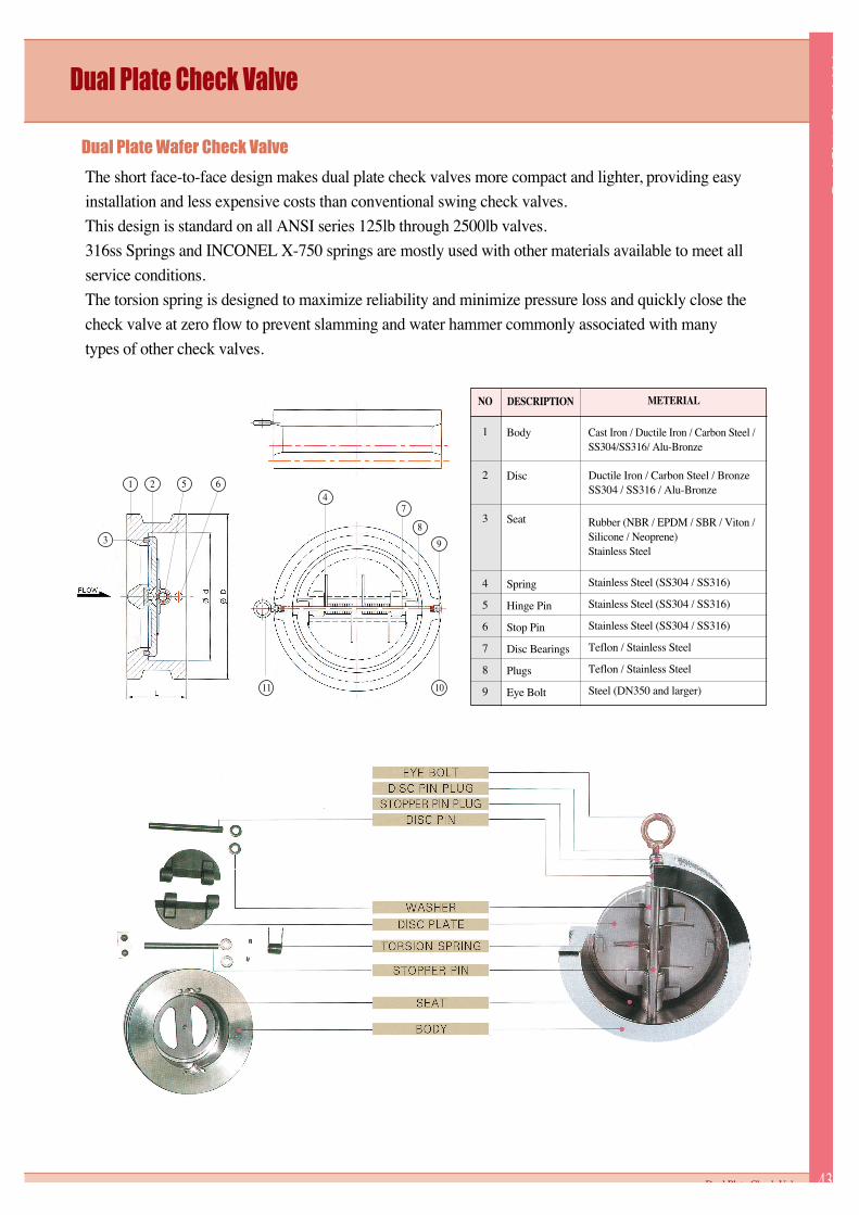
NO
1
2
3
4
5
6
7
8
9
Body
Disc
Seat
Spring
Hinge Pin
Stop Pin
Disc Bearings
Plugs
Eye Bolt
Stainless Steel (SS304 / SS316)
Stainless Steel (SS304 / SS316)
Stainless Steel (SS304 / SS316)
Teflon / Stainless Steel
Teflon / Stainless Steel
Steel (DN350 and larger)
Cast Iron / Ductile Iron / Carbon Steel /SS304/SS316/ Alu-Bronze
Ductile Iron / Carbon Steel / BronzeSS304 / SS316 / Alu-Bronze
Rubber (NBR / EPDM / SBR / Viton /Silicone / Neoprene)Stainless Steel
DESCRIPTION METERIAL
3
1 2 5 6
74
8
9
1011
Dual Plate Wafer Check Valve
The short face-to-face design makes dual plate check valves more compact and lighter, providing easy
installation and less expensive costs than conventional swing check valves.
This design is standard on all ANSI series 125lb through 2500lb valves.
316ss Springs and INCONEL X-750 springs are mostly used with other materials available to meet all
service conditions.
The torsion spring is designed to maximize reliability and minimize pressure loss and quickly close the
check valve at zero flow to prevent slamming and water hammer commonly associated with many
types of other check valves.

2”
2 1/2”
3”
4”
5”
6”
8”
10”
12”
14”
16”
18”
20”
24”
26”
28”
30”
32”
36”
40”
42”
48”
54”
60”
72”
50
65
80
100
125
150
200
250
300
350
400
450
500
600
650
700
750
800
900
1000
1050
1200
1350
1500
1800
60
73
89
114
141
168
219
273
324
356
406
457
508
610
660
711
762
813
914
1016
1067
1219
1372
1524
1829
2.4
2.9
3.5
4.5
5.6
6.6
8.6
10.7
12.8
14.0
16.0
18.0
20.0
24.0
26.0
28.0
30.0
32.0
36.0
40.0
42.0
48.0
54.0
60.0
72.0
60
67
73
73
86
98
127
146
181
184
191
203
219
222
222
305
305
356
368
419
432
524
540
660
914
2.4
2.6
2.9
2.9
3.4
3.9
5.0
5.7
7.1
7.2
7.5
8.0
8.6
8.7
8.7
12.0
12.0
14.0
14.5
16.5
17.0
20.3
21.3
26.0
36.0
60
67
73
73
86
98
127
146
181
222
232
264
292
318
318
318
368
368
483
483
568
629
629
650
650
2.4
2.6
2.9
2.9
3.4
3.9
5.0
5.7
7.1
8.7
9.1
10.4
11.5
12.5
12.5
12.5
14.5
14.5
19.0
19.0
22.4
24.8
24.8
25.6
25.6
60
67
73
79
105
136
165
213
229
273
305
362
368
438
438
438
505
505
635
635
701
701
701
750
750
2.4
2.6
2.9
3.1
4.1
5.4
6.5
8.4
9.0
10.7
12.0
14.3
14.5
17.2
17.2
17.2
19.9
19.9
25.0
25.0
27.6
27.6
27.6
29.5
29.5
105
124
137
175
197
222
279
340
410
451
514
549
606
718
773
832
883
940
1048
1162
1219
1384
1549
1715
2051
4.1
4.9
5.4
6.9
7.8
8.7
11.0
13.4
16.1
17.8
20.2
21.6
23.9
28.3
30.4
32.8
34.8
37.0
41.3
45.7
48.0
54.5
61.0
67.5
80.7
111
130
149
181
216
251
308
362
422
486
540
597
654
775
835
903
953
1006
1118
1115
1166
1274
1493
1645
-
4.4
5.1
5.9
7.1
8.5
9.9
12.1
14.3
16.6
19.1
21.3
23.5
25.7
30.5
32.9
35.6
37.5
39.6
44.0
43.9
45.9
50.2
58.8
64.8
-
111
130
149
194
241
267
321
400
457
492
565
613
683
791
867
915
968
1024
1130
1155
1220
1392
1556
1735
-
4.4
5.1
5.9
7.6
9.5
10.5
12.6
15.7
18.0
19.4
22.2
24.1
26.9
31.1
34.1
36.0
38.1
40.3
44.5
45.5
48.0
54.8
61.3
68.3
-
2.4
4.3
5.7
7.5
12
16
33
50
79
93
159
178
234
348
740
692
835
665
1197
1247
1405
1307
2895
3645
6375
mmmm in
inch
SIZE
VALVE DIMENSIONS
dL
150LB
mm in
Weight(kg)
150LB300LB
mm in
600LB
mm in
D
150LB
mm in
300LB
mm in
600LB
mm in
unit : mm
Specification and design are subject to change without notice
PRODUCT GUIDE44
DCW Series Dual Plate Check Valve / Wafer Type Dimension

2"
2 1/2"
3"
4"
5"
6"
8"
10"
12"
14"
16"
18"
20"
24"
26"
28"
30"
32"
36"
40'
42"
48"
54"
60"
72"
50
65
80
100
125
150
200
250
300
350
400
450
500
600
650
700
750
800
900
1000
1050
1200
1350
1500
1800
60
73
89
114
141
168
219
273
324
356
406
457
508
610
660
711
762
813
914
1016
1067
1219
1372
1524
1829
2.4
2.9
3.5
4.5
5.6
6.6
8.6
10.7
12.8
14.0
16.0
18.0
20.0
24.0
26.0
28.0
30.0
32.0
36.0
40.0
42.0
48.0
54.0
60.0
72.0
60
67
73
73
86
98
127
146
181
184
191
203
219
222
222
305
305
356
368
419
432
524
540
660
914
2.4
2.6
2.9
2.9
3.4
3.9
5.0
5.7
7.1
7.2
7.5
8.0
8.6
8.7
8.7
12.0
12.0
14.0
14.5
16.5
17.0
20.6
21.3
26.0
36.0
60
67
73
73
86
98
127
146
181
222
232
264
292
318
318
318
368
368
483
483
568
629
629
650
650
2.4
2.6
2.9
2.9
3.4
3.9
5.0
5.7
7.1
8.7
9.1
10.4
11.5
12.5
12.5
12.5
14.5
14.5
19.0
19.0
22.4
24.8
24.8
25.6
25.6
60
67
73
79
105
136
165
213
229
273
305
362
368
438
438
438
505
505
635
635
701
701
701
750
750
2.4
2.6
2.9
3.1
4.1
5.4
6.5
8.4
9.0
10.7
12.0
14.3
14.5
17.2
17.2
17.2
19.9
19.9
25.0
25.0
27.6
27.6
27.6
29.5
29.5
165
191
210
229
254
279
343
406
483
533
597
635
699
813
870
927
984
1060
1168
1289
1346
1511
1683
1854
2197
6.5
7.5
8.3
9.0
10.0
11.0
13.5
16.0
19.0
21.0
23.5
25.0
27.5
32.0
34.3
36.5
38.7
41.7
46.0
50.7
53.0
59.5
66.3
73.0
86.5
165
191
210
254
279
318
381
445
521
584
648
711
775
914
972
1035
1092
1149
1270
1238
1289
1416
1657
1810
-
6.5
7.5
8.3
10.0
11.0
12.5
15.0
17.5
20.5
23.0
25.5
28.0
30.5
36.0
38.3
40.7
43.0
45.2
50.0
48.7
50.7
55.7
65.2
71.3
-
165
191
210
273
330
356
419
508
559
603
686
743
813
940
1016
1073
1130
1194
1314
1320
1403
1500
1778
1994
-
6.5
7.5
8.3
10.7
13.0
14.0
16.5
20.0
22.0
23.7
27.0
29.3
32.0
37.0
40.0
42.2
44.5
47.0
51.7
52.0
55.2
59.5
70.0
78.5
-
7.4
7.4
8.4
13.5
16
22
44
86
100
127
162
190
254
403
482
543
696
855
1220
1410
1560
1770
1865
2110
2435
mmmm in
inch
SIZE
VALVE DIMENSIONS
dL
150LB
mm in
Weight(kg)
150LB300LB
mm in
600LB
mm in
D
150LB
mm in
300LB
mm in
600LB
mm in
unit : mm
Specification and design are subject to change without notice
DlP
lt
Ch
kV
l
45Dual Plate Check Valve
DCF Series Dual Plate Check Valve / Flange Type Dimension
PRODUCT GUIDE46
Engineerring Data & Installation
Engineerring Data
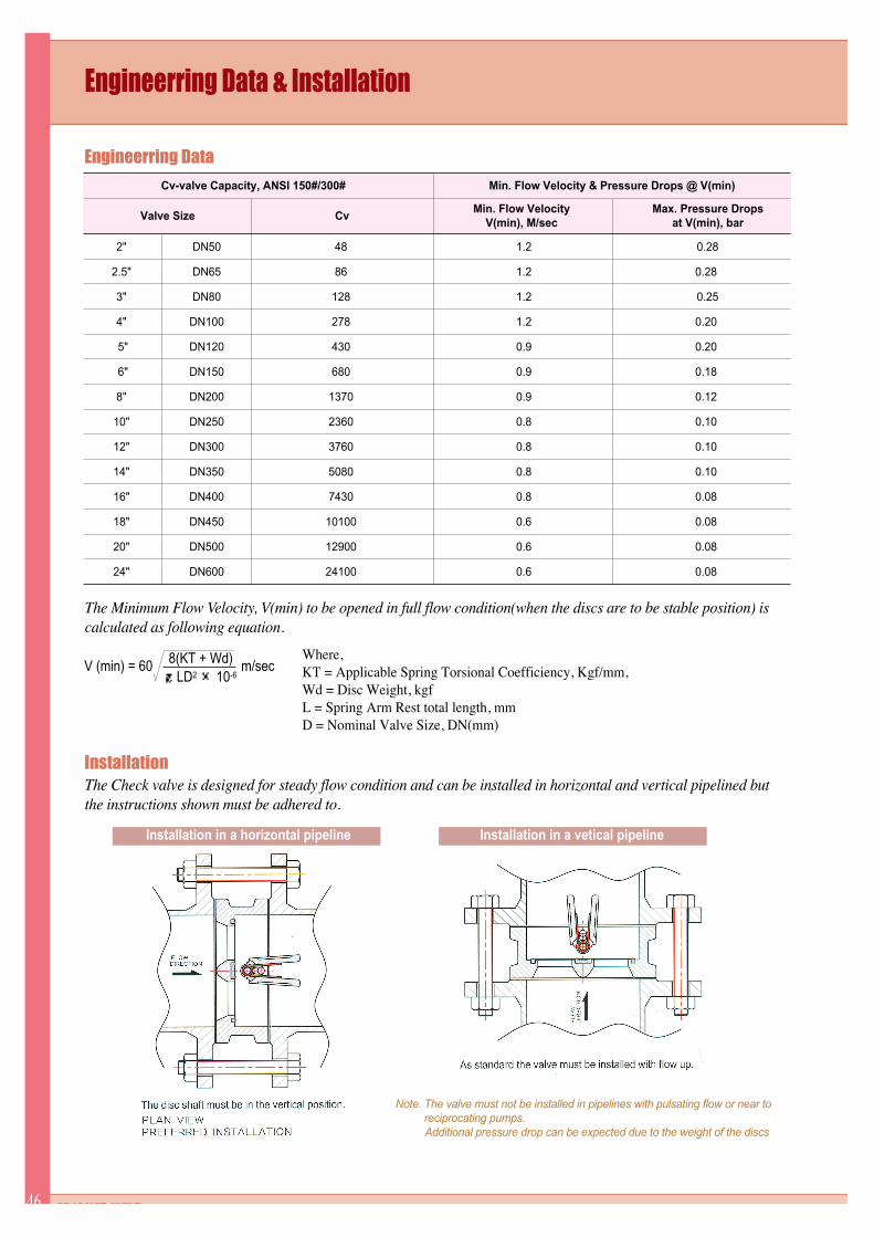
Installation
The Minimum Flow Velocity, V(min) to be opened in full flow condition(when the discs are to be stable position) iscalculated as following equation.
The Check valve is designed for steady flow condition and can be installed in horizontal and vertical pipelined butthe instructions shown must be adhered to.
Where,KT = Applicable Spring Torsional Coefficiency, Kgf/mm,Wd = Disc Weight, kgfL = Spring Arm Rest total length, mmD = Nominal Valve Size, DN(mm)
2"
2.5"
3"
4"
5"
6"
8"
10"
12"
14"
16"
18"
20"
24"
DN50
DN65
DN80
DN100
DN120
DN150
DN200
DN250
DN300
DN350
DN400
DN450
DN500
DN600
48
86
128
278
430
680
1370
2360
3760
5080
7430
10100
12900
24100
1.2
1.2
1.2
1.2
0.9
0.9
0.9
0.8
0.8
0.8
0.8
0.6
0.6
0.6
0.28
0.28
0.25
0.20
0.20
0.18
0.12
0.10
0.10
0.10
0.08
0.08
0.08
0.08
V (min) = 60 m/secLD2 10-6
8(KT + Wd)
Cv-valve Capacity, ANSI 150#/300#
Valve Size CvMin. Flow Velocity
V(min), M/secMax. Pressure Drops
at V(min), bar
Min. Flow Velocity & Pressure Drops @ V(min)
Note. The valve must not be installed in pipelines with pulsating flow or near toreciprocating pumps.Additional pressure drop can be expected due to the weight of the discs
Installation in a horizontal pipeline Installation in a vetical pipeline

Ct
Lid
Btt
flV
l
9Rubber Lined Butterfly Valve
DCF Series Flange Type Valves
SWV IS BEST TECHNOLOGY!Creating a better tomorrow with advanced technology and
the spirit of Creativity and Challenge SWV builds a brighter future for thee.
Specification Of Actuators
Electric actuator
Spur Gear
Cylinder actuatorHydraulic actuator
Drop-weight actuatorwith oil cylinder
Worm gear typewith actuator
flange
Worm gear direct type
Butterfly Valves
Chain wheel Square cap Handwheel Bevel gear Cylinder actuator