triconex approved topical report - nrc.gov · rxm remote extender module sdpe special dedication...
TRANSCRIPT

NUCLEAR QUALIFIED PRODUCTS
TRICONEX APPROVED TOPICAL REPORT
7286-545-1-A Revision 4
NUCLEAR QUALIFICATION OF V10 TRICON TRIPLE MODULAR REDUNDANT (TMR) PLC SYSTEM
NRC Approved Version (TAC No. ME2435) Issue Date: May 15, 2012

Triconex Approved Topical Report Document No.: 7286-545-1-A Revision: 4 Date: May 15, 2012
Contents
PART 1: Final Safety Evaluation for Invensys Operations Management Triconex Topical Report, including
NRC Transmittal Letter dated April 12, 2012, and
Safety Evaluation Report (SER) dated April 12, 2012
PART 2: Request for Additional Information (RAI)
PART 3: Abstract of Topical Report
PART 4: Triconex Topical Report 7286-545-1, Revision 4
PART 5: Appendix A to Triconex Topical Report 7286-545-1 (EPRI TR-107330 Compliance Traceability Matrix)
PART 6: Appendix B to Triconex Topical Report 7286-545-1 (Application Guide)

Triconex Approved Topical Report Document No.: 7286-545-1-A Revision: 4 Date: May 15, 2012
PART 1
Final Safety Evaluation for Invensys Operations Management Triconex Topical Report, including:
NRC Transmittal Letter dated April 12, 2012 (Accession No. ML120900889)
Safety Evaluation Report (SER) dated April 12, 2012
(Accession No. ML120900890)

April 12, 2012
Mr. Brian Haynes Invensys Operations Management North America Delivery 26561 Rancho Parkway South Lake Forest, CA 92630 SUBJECT: FINAL SAFETY EVALUATION FOR INVENSYS OPERATIONS MANAGEMENT
“TRICONEX TOPICAL REPORT” (TAC NO. ME2435) Dear Mr. Haynes: By letters dated September 9, 2009, November 13, 2009, July 11, 2010, and January 5, 2011 (Agencywide Documents Access and Management System (ADAMS) Accession Nos. ML092870628, ML093370293, ML102040054, and ML110140444), Invensys Operations Management (Invensys) submitted Topical Report (TR) 7286-545-1, Revision 4, “Triconex Topical Report,” describing the platform upgrade (V10.5.1) to the U.S. Nuclear Regulatory Commission (NRC) staff for review. By letter dated December 23, 2011, an NRC draft safety evaluation (SE) regarding our approval of the Triconex Topical Report was provided for your review and comment (ADAMS Accession No. ML112840430). By letter dated February 7, 2012 (ADAMS Accession No. ML12047A030), Invensys commented on the draft SE. The NRC staff's disposition of Invensys’ comments on the draft SE are discussed in the attachment to the final SE enclosed with this letter. The NRC staff has found that Triconex Topical Report is acceptable for referencing in licensing applications for nuclear power plants to the extent specified and under the limitations delineated in the TR and in the enclosed final SE. The final SE defines the basis for our acceptance of the TR. Our acceptance applies only to material provided in the subject TR. We do not intend to repeat our review of the acceptable material described in the TR. When the TR appears as a reference in license applications, our review will ensure that the material presented applies to the specific plant involved. License amendment requests that deviate from this TR will be subject to a plant-specific review in accordance with applicable review standards. In accordance with the guidance provided on the NRC website, we request that Invensys publish approved proprietary and non-proprietary versions of this TR within three months of receipt of this letter. The approved versions shall incorporate this letter and the enclosed final SE after the title page. Also, they must contain historical review information, including NRC requests for additional information and your responses. The approved versions shall include an "-A" (designating approved) following the TR identification symbol.

B. Haynes - 2 - If future changes to the NRC's regulatory requirements affect the acceptability of this TR, Invensys and/or licensees referencing it will be expected to revise the TR appropriately, or justify its continued applicability for subsequent referencing.
Sincerely, /RA/
Robert A. Nelson, Deputy Director Division of Policy and Rulemaking Office of Nuclear Reactor Regulation
Project No. 709 Enclosure: Final SE

B. Haynes - 2 - If future changes to the NRC's regulatory requirements affect the acceptability of this TR, Invensys and/or licensees referencing it will be expected to revise the TR appropriately, or justify its continued applicability for subsequent referencing.
Sincerely, /RA/
Robert A. Nelson, Deputy Director Division of Policy and Rulemaking Office of Nuclear Reactor Regulation
Project No. 709 Enclosure: Final SE DISTRIBUTION: PUBLIC PLPB R/F RidsNrrDpr RidsNrrDprPlpb JRowley RidsNrrLADBaxley RidsOgcMailCenter RidsAcrsAcnwMailCenter RidsNrrDe RidsNrrDeEicb JJolicoeur (Hardcopy) ADAMS Accession No.: ML120900889; Pkg.: ML12093A156 NRR-043 OFFICE PLPB/PM PLPB/LA EICB/BC PLPB/BC DPR/DD
NAME JRowley DBaxley JThorp JJolicoeur RNelson
DATE 4/9/2012 4/9/2012 4/9/2012 4/11/2012 4/12/2012
OFFICIAL RECORD COPY

ENCLOSURE
FINAL SAFETY EVALUATION BY THE OFFICE OF NUCLEAR REACTOR REGULATION
TRICONEX TOPICAL REPORT 7286-545-1, REVISION 4
INVENSYS OPERATIONS MANAGEMENT
PROJECT NO. 709

ii
List of Acronyms AC alternating current AI analog input AO analog output ASAI application-specific action item ASIC application-specific integrated circuit BTP branch technical position CE conducted emissions CFR Code of Federal Regulations CGD commercial grade dedication COTS commercial off-the-shelf CRC cyclical redundancy check CS conducted susceptibility D3 diversity and defense-in-depth DAC digital-to-analog converter DC direct current DI digital input DI&C digital instrumentation and controls DO digital output EDM Engineering Department Manual EFT electrically fast transients EIA Electronics Industries Association EMI electromagnetic interference EMP electronic main processor EPRI Electric Power Research Institute ESD electrostatic discharge ETSX 3008N operating system FMEA failure modes and effects analysis FPGA field-programmable gate array GDC General Design Criterion GL Generic Letter HICRc Highly-Integrated Control Rooms – Communications Issues I&C instrumentation and control IEC International Electrotechnical Commission IEEE Institute of Electrical and Electronics Engineers I/O input and output IOM Invensys Operations Management (Tricon V10 vendor) ISG Interim Staff Guidance LTR Licensing Topical Report MIL-STD Military Standard MVDU maintenance video display unit NRC U.S. Nuclear Regulatory Commission NSR non-safety-related OS operating system PC personal computer PCB printed circuit board PDS pre-developed software PLC programmable logic controller QA quality assurance QAM Quality Assurance Manual QPM Quality Procedures Manual RAI Request for Additional Information

iii
RAM random-access memory RE radiated emissions RFI radio-frequency interference RG regulatory guide RPS Reactor Protection Systems RRS required response spectrum RS radiated susceptibility RS Recommended Standard RTC real-time clock RTD resistance temperature detector RTM requirements traceability matrix RXM remote extender module SDPE Special Dedication Parts Evaluation SDS software design specification SE safety evaluation SMP Software Management Plan SOE sequence of events SOP Software Operations Plan SPDS Safety Parameter Display System SQAP Software Quality Assurance Plan SR safety-related SRP Standard Review Plan SRS software requirements specification SSE safe shutdown earthquake Std Standard STP Software Test Plan SVDU safety video display unit SVVP Software Verification and Validation Plan TCM Tricon Communication Module TR Technical Report TRS test response spectrum TS technical specification TSAP test system application program TXS TELEPERM XS V&V verification and validation

iv
Table of Contents 1.0 Introduction ......................................................................................................... 1 2.0 Regulatory Evaluation ......................................................................................... 2 2.1 Scope of Triconex Platform Changes V9.5.3 to V10.5.1 ...................................... 2 2.2 Regulatory Criteria............................................................................................... 5 2.3 Precedents .......................................................................................................... 9 3.0 Technical Evaluation ............................................................................................ 9 3.1 Tricon V10 Platform Description ........................................................................ 10 3.1.1 Tricon V10 System Overview ............................................................................. 10 3.1.2 Tricon V10 System Hardware ............................................................................ 11 3.1.3 Tricon V10 System Software ............................................................................. 23 3.2 Development Process ....................................................................................... 28 3.2.1 Tricon V10 Software Design Review .................................................................. 29 3.2.2 Commercial Grade dedication of predeveloped software ................................... 32 3.3 Environmental qualification ................................................................................ 35 3.3.1 Test system configuration .................................................................................. 38 3.3.2 Pre-Qualification Testing .................................................................................... 39 3.3.3 Radiation WITHSTAND Test .............................................................................. 40 3.3.4 Temperature and Humidity Testing .................................................................... 41 3.3.5 Seismic Withstand Testing ................................................................................. 43 3.3.6 EMI/RFI Withstand Testing ................................................................................ 48 3.3.7 Surge Withstand Testing .................................................................................... 53 3.3.8 Electrostatic Discharge Withstand Testing ......................................................... 55 3.3.9 Class 1E to Non-1E Isolation Testing ................................................................. 57 3.3.10 Performance Proof Testing ................................................................................ 60 3.4 Platform Integrity Characteristics ....................................................................... 63 3.4.1 Response time .................................................................................................. 63 3.4.2 Deterministic Performance ................................................................................ 64 3.4.3 Diagnostics and Self-Test Capabilities ............................................................... 65 3.5 Failure Modes and Effects Analysis ................................................................... 67 3.6 Reliability and Availability Analysis ..................................................................... 68 3.7 Communications Independence ........................................................................ 68 3.7.1 Communications with Safety Channels/Divisions .............................................. 70 3.7.2 Communications With Non-Safety Systems....................................................... 71 3.7.3 Staff Guidance in DI&C-ISG-04 ......................................................................... 74 3.8 Secure Development and Operational Environment .......................................... 97 3.8.1 Lifecycle Phases ............................................................................................... 97 3.9 Diversity and Defense-in-Depth ....................................................................... 112 3.10 Conformance with IEEE STD 603-1991 ........................................................... 112 3.10.1 IEEE 603-1991 Clause 4, “Safety System Designation” .................................. 113 3.10.2 IEEE STD 603-1991 Clause 5, “Safety System Criteria” .................................. 113 3.10.3 IEEE STD 603-1991 Clause 6, “Sense and Command Features – Functional and
Design Requirements” ..................................................................................... 127 3.10.4 IEEE STD 603-1991 Clause 7, “Execute Features – Functional and Design
Requirements” ................................................................................................. 128 3.10.5 IEEE STD 603-1991 Clause 8, “Power Source Requirements” ........................ 129 3.11 Conformance with IEEE STD 7-4.3.2-2003 ..................................................... 130 3.11.1 IEEE STD 7-4.3.2-2003 Clause 5, “Safety System Criteria” ............................. 130 3.12 Summary of Regulatory Compliance ............................................................... 140 4.0 Limitations and Conditions ............................................................................... 142 4.1 Generic Open Items ........................................................................................ 142

v
4.2 Plant-Specific Action Items .............................................................................. 142 5.0 Conclusion ...................................................................................................... 147 6.0 References ...................................................................................................... 147

FINAL SAFETY EVALUATION BY THE
OFFICE OF NUCLEAR REACTOR REGULATION
TRICONEX TOPICAL REPORT 7286-545-1, REVISION 4
INVENSYS OPERATIONS MANAGEMENT
PROJECT NO. 709
1.0 INTRODUCTION
By letter dated September 9, 2009 (Reference 1), as supplemented by letters dated November 13, 2009 (Reference 2), and July 11, 2010 (Reference 3), Invensys Operations Management (IOM) requested U.S. Nuclear Regulatory Commission (NRC) approval for the “Triconex Topical Report,” IOM Document No. 7286-545-1, Revision 4 (Reference 4), hereafter referred to as the licensing topical report (LTR). The supplemental documents provided under the cover letter dated September 22, 2009, and the subsequent cover letters dated from October 30, 2009, through August 12, 2011, provided additional information that clarified and supported the technical claims documented in the LTR and did not expand or change the scope of the LTR. The LTR was accepted for review by letter dated August 11, 2010 (Reference 67). The acceptance letter identified IOM commitments to supply supplemental documents. These documents provide additional information to support the review of the design details and qualification of the Tricon V10 platform and were submitted under the cover letter dated August 5, 2010, with an enclosure (Reference 59) providing summary responses to NRC inquiries for clarification within the acceptance letter. The LTR revision describes the completion of all testing and documentation requirements of Electric Power Research Institute (EPRI) Technical Report (TR)-107330 for Version 10.5.1 (V10) of the Tricon Triple Modular Redundant (TMR) Programmable Logic Controller (PLC) platform, which is an evolutionary upgrade to the NRC approved Version 9.5.3 (V9), documented in Triconex Topical Report 7286-545-1-A, “Qualification Summary Report,” (Reference 34). The current LTR revision includes a summary of the equipment qualification for the Tricon V10 and a synopsis of the differences between the Tricon V9 System and the Tricon V10 System. The NRC staff conducted an audit at the IOM facility in Irvine, California, on December 15 -17, 2010 (Reference 6). The purpose of the audit was to inspect IOM procedures and processes that are referenced in the LTR and audit documented products of commercial grade dedication activities. During the site visit, thread audits were performed, the hardware configuration of the Tricon qualification test specimen was observed, and performance characteristics and functional capabilities of the platform were observed. The results of the audit are documented in the March 14, 2011, Audit Report (Reference 6). The NRC’s approval of the Tricon V9 platform is documented in its safety evaluation report (SER), “Review of Triconex Corporation Topical Reports 7286-545, “Qualification Summary Report” and 7286-546, “Amendment 1 to Qualification Summary Report, Revision 1” (TAC NO. MA8283)” (Reference 9), which formed the basis for the NRC staff’s safety evaluation (SE) of the Tricon V10 platform. The NRC staff focused its review efforts on the impact of V10 platform changes on the V9 platform safety conclusions documented in the SE. For those hardware and

– 2 –
software items that are common to both the V9 and V10 platforms, the NRC’s approval is documented in the V9 platform SE. However, changes to review guidance since 2001 required some aspects of the V9 platform to be reevaluated or evaluated in greater detail and the regulatory findings are documented herein. 2.0 REGULATORY EVALUATION
The purpose of this SE is to evaluate whether the Tricon V10.5.1 platform is suitable for use in safety-related (SR) applications in nuclear power plants (NPP). Thus, the review of the LTR and supporting technical documents is intended to determine whether sufficient evidence is presented to enable a determination with reasonable assurance that subsequent licensing applications referencing this platform can comply with the applicable regulations to ensure that the public health and safety will be protected. This evaluation and associated audit activities are not intended to completely assess all aspects of the design and implementation of any specific SR application (e.g., reactor protection system or engineered safeguards actuation system) and full compliance with relevant regulations will need to be evaluated on a plant-specific basis. However, the review scope is sufficient to allow the reviewer to reach the conclusion of reasonable assurance within the platform-level context. 2.1 SCOPE OF TRICONEX PLATFORM CHANGES V9.5.3 TO V10.5.1
The Tricon V10 PLC system is designed and built with the same basic architecture as the V9 PLC system. It is a fault-tolerant PLC that uses a triple modular redundant (TMR) architecture in which three parallel control paths are integrated into a single overall system. The system is designed to use two-out-of-three voting with the intent of providing uninterrupted process operation with no single point of random hardware failure. However, many of the previously approved components within the V9 platform have been updated or replaced in the V10 platform. The most prominent changes to the Tricon V10 platform are the main processor (MP) module and the communications module. The Tricon V9.5.3 MP module, 3006N MP is replaced by the 3008N MP in the Tricon V10.5.1. Multiple communications modules available for V9.5.3 have been replaced with a single module configuration, the Tricon Communication Module (TCM). The complete list of hardware (HW) and software (SW) changes implemented within the Tricon V10 platform is provided in Tables 1 and 2 below (Reference 10). The Tricon V9 HW and SW components are also listed for comparison. IOM included an Application Guide in Appendix B of the LTR that describes a generic safety system application using the V10 platform. The Application Guide was provided to facilitate a better understanding of the platform’s potential safety system applications in NPPs. However, the NRC staff did not make any safety determination regarding the Application Guide and this appendix is not approved by this SE. In addition to the V10 platform changes, IOM also submitted the Nuclear Safety Integration Program Manual (NSIPM) and an SE Maintenance Plan as part of the LTR. The NSIPM governs application specific development activities that occur at IOM’s facility. The SE Maintenance Plan describes IOM’s process to evaluate and document any future changes to the approved platform. The NRC staff reviewed these documents, but made no safety determinations on these programs and, therefore, they are not approved by this SE. It is an application-specific action item (ASAI) to review any application specific development activities governed by the NSIPM.

– 3 –
The NRC staff evaluated non-safety input and output (I/O) connections made to modules in a Remote Expansion Chassis IOM PN 8112N (as noted below in Table 1) that is part of a SR system as required by Clause 5.6 of Institute of Electrical and Electronics Engineers (IEEE) Standard (Std) 603-1991.
TABLE 1 – Summary of Hardware Changes
Module Tricon V9.5.3 System Tricon V10.5.1 System
Main Processor
3006N 3008N Hardware floating point processor
Embedded floating point software
Communication Module Three modules: • 4119AN (EICM) • 4329N (NCM) • 4609N (ACM)
One module: • 4352AN (TCM) Fiber
Optic
I/O Modules Analog Input (AI)
3700AN (0-5 VDC) 3721N (0-5 or -5 to +5 VDC, Differential) Next Generation Module, SMT
3701N (0-10 VDC) – Through Hole
3701N2 (0-10 VDC) - SMT
3510N (Pulse Input) 3511N (Pulse Input) – Faster Input Scan
3703EN (Isolated) Same 3708EN (ITC) Same 3704EN (0-5/0-10 VDC, High Density)
Removed
3706AN (NITC) Removed I/O Modules Analog Output (AO)
3805EN (4-20 mA) 3805HN (4-20 mA) – Supports increased inductive loads
I/O Modules Digital Input (DI)
3501TN 115V AC/DC – Through Hole
3501TN2 115V AC/DC – SMT
3502EN 48V AC/DC – Through Hole
3502EN2 48V AC/DC – SMT
3503EN 24V AC/DC – Through Hole
3503EN2 24V AC/DC – SMT
3504EN 24/48 VDC – Through Hole
Removed
3505EN 24 VDC – Through Hole
Removed
I/O Modules Digital Output (DO)
3604EN 24 VDC 3624N 24 VDC, Supervised
3625N 24 VDC, Supervised/ Unsupervised Next Generation Module
3601TN 115 VAC Same 3603TN 120 VDC Same 3607EN 48 VDC Same 3623TN 120 VDC, Supervised Same 3636TN (Relay Output) Same
Remote Extender Modules: Primary Remote
4210N (Single Mode Fiber Optic cable) 4211N (Single Mode Fiber Optic cable)
4200N (Multi Mode Fiber Optic cable) 4201N (Multi Mode Fiber Optic cable)
I/O Module Term Panels Version 8 Term Panels Version 9 Term Panels
Removed

– 4 –
Module Tricon V9.5.3 System Tricon V10.5.1 System
9794-110N PI 9782-110N AI 9561-810N DI 9561-110N DI 9664-810N DO 9663-610N DO 9563-810N DI 9662-810N DO 9662-610N DO 9668-110N RO 9667-810N DO 9562-810N DI 9783-110N AI 9795-610N AI 9790-610N AI 9764-310N AI 9860-610N AO
Signal Conditioners
Signal Conditioner (-100 to 100 °C) Pt (7B34-01-1) Signal Conditioner (0 to 100 °C) Pt (7B34-02-1) Signal Conditioner (0 to 200 °C) Pt (7B34-03-1) Signal Conditioner (0 to 600 °C) Pt (7B34-04-1)
Same
Not included
Four additional Signal Conditioners: 7B34-CUSTOM (0 to 200 °C) 7B34-CUSTOM (0 to 600 °C) 7B30-02-1 (0 to 100 mV) 7B14-C-02-1 (0 to 120 °C)
Power Supplies: 120 V
24 VDC 230 VAC
ASTEC Power Modules Vicor Power Modules 8310N 8311N
8310N2 8311N2 8312N2
Chassis: Main
Expansion Remote Expansion*
8110N 8111N 8112N
8110N2 8111N 8112N
*Remote Expansion Chassis PN 8112N may be configured as non-safety

– 5 –
TABLE 2 – Summary of Software Changes Module Tricon V9.5.3 System
Software Version Tricon V10.5.1 System Software Version
TriStation 1131 Developer’s Workbench (Application Development Software)
v3.1 v4.7.0
Main Processor Software: Application Processor I/O Processor COM Processor
TSX 5211 IOC 5212 COM 5206
ETSX 6271 IOCCOM 6054
Communication Module Software: TCM Common V9.5.3 COM EICM NCM ACM
Not Applicable ICM 4930 IICX 5276 NCMX 5028 ACMX 5203
TCM 6276 Not Applicable Not Applicable Not Applicable Not Applicable
I/O Module Software:
AI 3721N
Not Applicable
AI 6256
DO 3625N Not Applicable DO 6255 AI 3701N/N2 AI/NITC 4873 AI/NITC 5661
IAI 3703EN EIAI/ITC 5491 EIAI/ITC 5916 ITC 3708EN EIAI/ITC 5491 EIAI/ITC 5916
PI 3510N PI 4559 Not Applicable PI 3511N Not Applicable PI 5647
AO 3805EN/HN EAO 5595 EAO 5897 DI 3501TN/TN2
DI 3502EN /EN2 DI 3503EN/EN2
EDI 5490 EDI 5909
DI 3505EN EDI 5490 Not Applicable DI 3504EN HDI 5499
AI 3704EN HDI 5499 DO 3601TN DO 3607EN
EDO 5488 EDO 5781
DO 3604EN EDO 5488 Not Applicable RO 3636TN ERO 5497 ERO 5777 DO 3603TN TSDO 5502 TSDO/HVDO 6273 DO 3623TN TSDO 5502 TSDO2 5940
DO 3624N TSDO 5502 Not Applicable Remote Extender Modules RXM 3310 Same
2.2 REGULATORY CRITERIA
The acceptance criteria used as the basis for this review are defined in NUREG-0800, “Standard Review Plan for the Review of Safety Analysis Reports for Nuclear Power Plants,” Revision 5, dated March 2007. NUREG-0800, which is referred to as the Standard Review Plan (SRP), sets forth a method for reviewing compliance with applicable sections of Title 10 Part 50 of the Code of Federal Regulations ( 10 CFR), “Domestic Licensing of Production and Utilization Facilities.” Specifically, SRP Chapter 7, “Instrumentation and Controls,” addresses the

– 6 –
requirements for instrumentation and control (I&C) systems in nuclear power plants based on light-water reactor designs. The procedures for review of digital systems applied in this evaluation are principally contained within SRP Chapter 7 and are augmented and supplemented by Interim Staff Guidance (ISG). The suitability of a digital platform for use in safety systems depends on the quality of its components; quality of the design process; and system implementation aspects such as real-time performance, independence, and online testing. Because this equipment is intended for use in safety systems and other SR applications, the submitted LTR was evaluated in accordance with the provisions of IEEE Std 603-1991, “IEEE Standard Criteria for Safety Systems for Nuclear Power Generating Stations,” and IEEE Std 7-4.3.2-2003, “IEEE Standard Criteria for Digital Computers in Safety Systems of Nuclear Power Generating Stations,” based on the guidance contained in SRP Chapter 7, Appendix 7.1-C, “Guidance for Evaluation of Conformance to IEEE Std 603,” and Appendix 7.1-D, “Guidance for Evaluation of the Application of IEEE Std 7-4.3.2,” which provide acceptance criteria for these two standards. SRP Chapter 7, Table 7-1, “Regulatory Requirements, Acceptance Criteria, and Guidelines for Instrumentation and Control Systems Important to Safety,” identifies design criteria and regulations from 10 CFR Part 50 that are applicable to I&C systems and are relevant for general review of the suitability of a digital I&C (DI&C) platform for generic SR applications. Many of the review criteria of the SRP depend on the design of an assembled system for a particular application, whereas the LTR presents the elements of hardware and system software in the Tricon V10 platform that can be used in a variety of safety applications. Since no plant-specific application of the platform as a safety system is associated with the LTR, this SE is limited to the evaluation of compliance with the relevant regulations and guidance documents to the degree to which they can be satisfied at the platform level. In effect, fulfillment of system-level requirements can only be partially evaluated on a generic basis based on the capabilities and characteristics of the Tricon V10 platform. Determination of full compliance with the applicable regulations remains subject to plant specific licensing review of a full system design based on the Tricon V10 platform. Thus, it is an ASAI to establish full compliance with the design criteria and regulations identified in SRP Chapter 7, Table 7-1, which are relevant to specific applications of DI&C systems at the time the application is submitted to NRC for approval. This and other ASAIs identified in the evaluation documented in Section 3 are compiled in Section 4.2 of this report. The following regulations and design criteria in 10 CFR Part 50 are applicable in whole or in part for general review of the suitability of this I&C platform for generic SR applications at NPPs:
• 10 CFR 50.55a(a)(1), “Quality Standards for Systems Important to Safety,” requires that “structures, systems, and components must be designed, fabricated, erected, constructed, tested, and inspected to quality standards commensurate with the importance of the safety function to be performed”
• 10 CFR 50.55a(h), “Protection and safety systems,” incorporates by reference the 1991 version of IEEE Std 603, “IEEE Standard Criteria for Safety Systems for Nuclear Power Generating Stations,” including the correction sheet dated January 30, 1995
• 10 CFR Part 50, Appendix A, “General Design Criteria for Nuclear Power Plants” • General Design Criterion (GDC) 1, “Quality Standards and Records” • GDC 2, “Design Basis for Protection Against Natural Phenomena” • GDC 4, “Environmental and Dynamic Effects Design Basis” • GDC 13, “Instrumentation and Control”
– 7 –
• GDC 20, “Protection System Functions” • GDC 21, “Protection System Reliability and Testability” • GDC 22, “Protective System Independence” • GDC 23, “Protective System Failure Modes” • GDC 24, “Separation of Protection and Control” • GDC 25, “Protection System Requirements for Reactivity Control Malfunctions” • GDC 29, “Anticipated Operational Occurrences”
SRP Chapter 7, Table 7-1, identifies regulatory guides (RGs), branch technical positions (BTPs), and industry standards that contain information, recommendations, and guidance and, in general, provide an acceptable basis to implement the above requirements for both hardware and software features of SR DI&C systems. Based on the scope of the Tricon V10 platform and the limitations of a platform-level review, the following guides and positions are determined to have relevance for consideration in this SE:
Note: Revision levels are identified here and not listed throughout the SE. • RG 1.22, Revision -, “Periodic Testing of Protection System Actuation Functions” • RG 1.47, Revision 1, “Bypassed and Inoperable Status Indication for Nuclear Power
Plant Safety Systems” • RG 1.53, Revision 2, “Application of the Single-Failure Criterion to Nuclear Power Plant
Protection Systems” • RG 1.62, Revision -, “Manual Initiation of Protection Actions” • RG 1.75, Revision 3, “Physical Independence of Electrical Systems” • RG 1.89, Revision 1, “Qualification for Class 1E Equipment for Nuclear Power Plants” • RG 1.97, Revision 4, “Instrumentation for Light-Water-Cooled Nuclear Power Plants to
Assess Plant and Environs Conditions During and Following an Accident” • RG 1.100, Revision 3, “Seismic Qualification of Electric and Mechanical Equipment for
Nuclear Power Plants,” which conditionally endorses IEEE Std 344-1987, “IEEE Recommended Practices for Seismic Qualification of Class 1E Equipment for Nuclear Power Generation Stations”
• RG 1.152, Revision 3, “Criteria for Digital Computers in Safety Systems of Nuclear Power Plants,” which endorses IEEE Std 7-4.3.2-2003, “Application Criteria for Programmable Digital Computer Systems in Safety Systems of Nuclear Power Generating Stations”
• RG 1.168, Revision 1, “Verification, Validation, Reviews and Audits for Digital Computer Software Used in Safety Systems of Nuclear Power Plants,” which endorses IEEE Std 1012-1986, “IEEE Standard for Software Verification and Validation Plans,” and IEEE Std 1028-1988, “IEEE Standard for Recommended Practices for Software Design Descriptions”
• RG 1.169, Revision -, “Configuration Management Plans for Digital Computer Software Used in Safety Systems of Nuclear Power Plants,” which endorses IEEE Std 828-1990, “Software Configuration Management Plans,” and IEEE Std 1042-1987, “IEEE Guide to Software Management”
• RG 1.170, Revision -, “Software Test Documentation for Digital Computer Software Used in Safety Systems of Nuclear Power Plants,” which endorses IEEE Std 829-1983, “Software Test Documentation”
• RG 1.171, Revision -, “Software Unit Testing for Digital Computer Software Used in Safety Systems of Nuclear Power Plants,” which endorses IEEE Std 1008-1987, “IEEE Standard for Software Unit Testing”

– 8 –
• RG 1.172, Revision -, “Software Requirements Specification for Digital Computer Software Used in Safety Systems of Nuclear Power Plants,” which endorses IEEE Std 830-1984, “Guide for Software Requirements Specification”
• RG 1.173, Revision -, “Developing Software Life Cycle Processes for Digital Computer Systems used in Safety Systems of Nuclear Power Plants,” which endorses IEEE Std 1074-1995, “IEEE STD for Developing Software Life Cycle Processes”
• RG 1.180, Revision 1, “Guidelines for Evaluating Electromagnetic and Radio-Frequency Interference in Safety-Related Instrumentation and Control Systems,” which endorses IEEE Std 1050-1996, “IEEE Guide for Instrumentation and Control Equipment Grounding in Generating Stations,” and specified test methods from Military Standard (MIL-STD)-461E, “Requirements for the Control of Electromagnetic Interference Characteristics of Subsystems and Equipment” and International Electrotechnical Commission (IEC) 61000, “International Electrotechnical Commission Series of EMI/RFI Test Methods”
• RG 1.209, Revision -, “Guidelines for Environmental Qualification of Safety-Related Computer-Based Instrumentation and Control Systems in Nuclear Power Plants,” which endorses IEEE Std 323-2003, “IEEE Standard for Qualifying Class 1E Equipment for Nuclear Power Generating Stations”
• SRP BTP 7-14, “Guidance on Software Reviews for Digital Computer-Based Instrumentation and Control Systems”
• SRP BTP 7-17, “Guidance on Self-Test and Surveillance Test Provisions” • SRP BTP 7-21, “Guidance on Digital Computer Real-Time Performance” • DI&C-ISG-04, “Interim Staff Guidance on Highly-Integrated Control Rooms –
Communications Issues (HICRc),” September 28, 2007.
The Tricon V10 is an upgrade product based on previous designs. Some design elements of the Tricon V10 pre-date IOM’s 10 CFR Part 50 Appendix B process and therefore certain industry guidelines that address dedication and qualification processes are applicable. The NRC staff has reviewed and accepted the following industry guidance documents based on conditions established in SE reports.
• EPRI TR-102323, “Guidelines for Electromagnetic Interference Testing in Power Plants,” as accepted by the NRC SE dated April 30, 1996
• EPRI TR-106439, “Guideline on Evaluation and Acceptance of Commercial Grade Digital Equipment for Nuclear Safety Applications,” as accepted by the NRC SE dated April 1997
• EPRI TR-107330, “Generic Requirements Specification for Qualifying a Commercially Available PLC for Safety-Related Applications in Nuclear Power Plants,” as accepted by the NRC SE dated July 30, 1998
It should be noted that industry standards, documents, and reports use the word “requirements” to denote provisions that must be implemented to ensure compliance with the corresponding document. Additionally, these standards, documents, and reports provide guidance or recommendations that need not be adopted by the user to ensure compliance with the corresponding document, and the optional items are not designated as “requirements.” The word “requirement” is used throughout the instrumentation and control discipline. However, licensee or vendor documentation of conformance to the “requirements” provided in industry standards, documents, and reports referenced in this SE constitutes conformance with NRC regulatory requirements only insofar as the standards, documents and reports are endorsed by the NRC. Other use of the word “requirements” in these documents does not indicate that the “requirements” are NRC regulatory requirements.

– 9 –
2.3 PRECEDENTS
Four topical reports for digital platforms have previously been approved by the NRC. These platforms are the HFC-6000, AREVA TELEPERM XS (TXS), the Westinghouse Common Q, and the Invensys Triconex, and they were generically qualified in accordance with the approved guidance of EPRI TR-107330. The corresponding SE reports (References 11, 12, 13, and 9 respectively) for these platforms document the findings of the reviews by NRC staff and constitute applicable precedents that are considered in the conduct of this review. Specific precedents employed to support this review address environmental qualification, exceptions to key performance requirements specified by EPRI TR-107330, and Commercial Grade Dedication (CGD) of previously developed software (PDS). Each of the SEs for the generic platforms (i.e., TXS, Common Q, and Tricon V9) addresses deficiencies in the environmental qualification program for the respective platforms either through treatment as generic open items or identification of a commitment to retest on a plant-specific basis. The SE for the Tricon V9 platform (Reference 9) provides a precedent for the treatment of exceptions to the response time performance requirement from EPRI TR-107330. The SE for the Common Q platform (Reference 13) provides an evaluation of dedication activities by Combustion Engineering Nuclear Power (now owned by Westinghouse) for commercial grade items, including software, which is used in the platform. The commercial dedication of a Siemens-designed application-specific integrated circuit (ASIC) for use as the system support controller on platform printed circuit boards (PCBs) provides a precedent from the SE for the TXS platform (Reference 12) regarding the treatment of custom chips that provide processor support functionality for board management. 3.0 TECHNICAL EVALUATION
This SE follows the guidance contained in SRP Chapter 7. Chapter 7 of the NRC SRP provides guidance on reviewing complete NPP designs of I&C systems. Revision 5 to SRP Chapter 7 also includes review criteria for digital systems. The guidance is applicable to the review of TRs for evaluating the suitability of generic digital platforms for SR use through consideration of general system requirements. Based on examination of SRP Chapter 7, Table 7-1, Appendix 7.0-A, “Review Process for Digital Instrumentation and Control Systems,” and Appendix 7.1-A, “Acceptance Criteria and Guidelines for Instrumentation and Control Systems Important to Safety,” the relevant regulatory requirements, BTPs, ISG, and acceptance criteria that can be addressed in part at the platform level are identified in Section 2.2 of this SE. The evaluation of the Tricon V10 platform against the identified acceptance criteria is documented in the following subsections. IOM designed and built the Tricon PLC system as a commercial grade system, rather than specifically for use in SR systems in NPPs. As a result, the design process was not governed by 10 CFR Part 50 Appendix B and the related process documentation may not be fully consistent with BTP HICB-14. EPRI TR-106439 and TR-107330 recognize that commercial design practices differ from nuclear specific design practices and discuss how the essential technical characteristics of products meet the requirements, intent, and quality characteristics needed for SR systems in NPPs. The evaluation described in this section is based on review of the information contained within the LTR. The Tricon V10 platform is described in Section 2.1 of the LTR. Sections 2.2 and 2.3 describe the product qualification. Section 5 of the LTR contains discussion of key safety system design topics, such as security, diversity, and communications. The material contained in these sections of the LTR was the principal focus of the SE and is the primary source of the

– 10 –
descriptive information on the Tricon V10 platform presented in this section. Supplemental documentation docketed by IOM provides supporting and/or clarifying information that was considered in this evaluation. Specific reference to the source documentation is given where key information or supporting evidence from any of these additional documents proved to be essential to the conduct of the evaluation. 3.1 TRICON V10 PLATFORM DESCRIPTION
This section provides an overview of the Tricon V10 system. A detailed description of the system is provided in the following IOM documents; “Technical Product Guide, Tricon systems” (Reference 15), and the “Planning and Installation Guide” (Reference 16). The specific hardware and software that has been qualified is identified in the “Master Configuration List” (Reference 17). Table 3-1 in Section 3.3 of this document lists the Tricon V10 modules that have been qualified for nuclear SR applications. 3.1.1 TRICON V10 SYSTEM OVERVIEW
A typical Tricon V10 system (for example, one division of a reactor protection system) would consist of one or more 19-inch rack or panel mounted chassis. Each Tricon V10 system includes a main chassis, illustrated in Figure 2-1, and may also include additional expansion chassis.
Figure 2-1 – Tricon V10 Main Chassis
Each chassis is powered by two independent, redundant power supplies, each capable of providing the full power requirements of the chassis. Thus, the system can withstand a power supply failure without interruption. The Tricon V10 is triple redundant from input terminal to output terminal, as shown in Figure 2-2. The triple modular redundant (TMR) architecture is intended to allow continued system operation in the presence of any single point of failure within the system. The TMR architecture is also intended to allow the Tricon V10 to detect and correct individual faults on-line, without interruption of monitoring, control, and protection capabilities. In the presence of a

– 11 –
fault, the Tricon V10 will alarm the condition, remove the affected portion of the faulted module from operation, and continue to function normally in a dual redundant mode. The system returns to the fully triple redundant mode of operation when the affected module is replaced. To facilitate module replacement, the Tricon V10 chassis includes provisions for a spare module, logically paired with a single input or output module. This design allows on-line, hot replacement of any module, under power while the system is running, with no impact on the operation of the application.
Figure 2-2 – Triple Modular Redundant Architecture Figure 2-2 shows the arrangement of the input, MP, and output modules. As shown, each input and output module includes three separate and independent input or output circuits or legs. These legs communicate independently with the three main processor modules. Standard firmware is resident on the MP modules for all three microprocessors as well as on the input and output modules and communication modules (not shown in Figure 2-2). 3.1.2 TRICON V10 SYSTEM HARDWARE
The main components of a Tricon V10 system are the chassis, the termination panels, the power supply modules, the main processor, I/O modules, and communication modules. Functional requirements for this hardware are specified in Section 4.3 of EPRI TR-107330. Compliance of the Tricon V10 hardware with these requirements is summarized in the Requirements Traceability Matrix (RTM), Appendix A of the LTR. A description of this hardware is provided below. 3.1.2.1 8110N2 MAIN CHASSIS
A Tricon V10 system consists of one main chassis (shown in Figure 2-1) and up to fourteen additional expansion chassis. The Tricon V10 main chassis supports the following modules:
• Two redundant power supply modules • Three main processors • Communications modules • I/O modules

– 12 –
The main chassis also has a key switch that sets the system operating mode:
• RUN – Normal operation with read-only capability by externally connected systems, including TriStation. Normally, the switch is set to this position and the key is removed and stored in a secure location.
• PROGRAM – Allows for control of the Tricon V10 system using an externally connected personal computer (PC) running the TriStation software, including application program downloads.
• STOP – Stops application program execution. • REMOTE – Allows writes to application program variables by a TriStation PC or by
MODBUS masters and external hosts. As shown in Figure 2-3, the Tricon V10 backplane is designed with dual independent power rails. Both power rails feed each of the three legs on each I/O module and each main processor module residing within the chassis. Power to each of the three legs is independently provided through dual voltage regulators on each module. Each power rail is fed from one of the two power supply modules residing in the chassis. Under normal circumstances, each of the three legs on each I/O module and each main processor module draw power from both power supplies through the dual power rails and the dual power regulators. If one of the power supplies or its supporting power line fails, the other power supply will increase its power output to support the requirements of all modules in the chassis. The Tricon V10 also has dual redundant batteries located on the main chassis backplane. If a total power failure occurs, these batteries maintain data and programs on the main processor modules for a period of six months. The system will generate an alarm when the battery power is too low to support the system. The 8110N main chassis approved for the Tricon V9 is functionally equivalent to the 8110N2 qualified with the Tricon V10. However, they are not interchangeable. 3.1.2.2 8111N EXPANSION CHASSIS
The expansion chassis is the same as approved for V9 and is used locally to increase the number of I/O modules in the Tricon V10 PLC system. The expansion chassis are interconnected via three separate RS-485 data links, one for each leg of the three I/O legs. If communication modules are installed, three separate RS-485 data links are required for the three communications busses. The Tricon expansion chassis can support the following modules:
• Two redundant power supply modules • Communications modules (in the first expansion chassis only) • I/O modules

– 13 –
Figure 2-3 – Tricon V10 Chassis Backplane Configuration
3.1.2.3 8112N REMOTE EXPANSION CHASSIS
The remote expansion chassis are similar to the expansion chassis, but are used for remote locations, rather than locally. As such, each remote expansion chassis has remote extender modules (RXMs) that serve as repeaters or extenders of the Tricon V10 I/O bus to allow communications with the main chassis and expansion chassis within a channel or a division. A single remote RXM chassis or module would not be configured to communicate with more than one channel/division. The Tricon V10 remote extender chassis uses the same type of power supplies as the main chassis, and has the same dual and redundant power bus arrangement. The 8112N remote expansion chassis was approved with the Tricon V9 and is unchanged as qualified with the Tricon V10. 3.1.2.4 4200N PRIMARY & 4201N REMOTE EXTENDER MODULES
RXMs are multi-mode fiber optic modules that allow expansion chassis to be located up to 1.2 miles away from the main chassis. An RXM connection consists of three identical modules, serving as repeaters/extenders of the Tricon I/O bus that also provide ground loop isolation.

– 14 –
Each RXM has single channel transmit and receive cabling ports. Each of the three 4200N Primary RXMs is connected to the 4201N remote RXMs housed in the remote chassis. Each pair of RXMs is connected with two fiber optic cables operating at a communication rate of 375 Kbaud. The interfacing cabling is unidirectional for each channel. One cable carries data transmitted from the primary RXM to the remote RXM. The second cable carries data received by the primary RXM from the remote RXM. The RXMs provide immunity against electrostatic and electromagnetic interference. The fiber optic cables provide Class 1E to Non-Class 1E isolation between a SR main chassis and a non-safety-related (NSR) expansion chassis. The Tricon V9 was qualified with the 4210N and 4211N primary and remote RXM set which used single mode fiber optic cable. The V10 was qualified with the 4200N Primary and 4201N remote RXM set which uses multimode fiber optic cable. Both use the same software (see Table 2 above) and differ in the type of fiber optic cable that is supported. The V10 supported multimode fiber optic cable is capable of a 1.2 mile span while the V9 supported single mode version is capable of a 7.5 mile span. Though both RXM sets have been qualified, they are not interchangeable across the platforms because they were not qualified as interchangeable. 3.1.2.5 EXTERNAL TERMINATION ASSEMBLIES
The external termination assemblies (ETAs) are printed circuit board panels used for landing field wiring. The panels contain terminal blocks, resistors, fuses, and blown fuse indicators. The standard panels are configured for specific applications (e.g., digital input, AI, etc.). The thermocouple input termination panel provides cold-junction temperature sensors and upscale, downscale, or programmable burnout detection. The resistance temperature device (RTD) termination panels include signal conditioning modules. Each termination panel includes an interface cable that connects the termination panel to the Tricon V10 chassis backplane. The following ETAs were qualified with the Tricon V10 platform: 9794-110N PI, 9782-110N AI, 9561-810N DI, 9561-110N DI, 9664-810N DO, 9663-610N DO, 9563-810N DI, 9662-810N DO, 9662-610N DO, 9668-110N RO, 9667-810NDO, 9562-810N DI, 9795-610N AI, 9790-610N AI, 9860-610N AO, 9764-310N AI, and 9783-110N AI. 3.1.2.6 8310N2, 8311N2, AND 8312N2 POWER SUPPLY MODULES
All power supply modules are rated for 175 watts, which is sufficient to supply the power requirements of all configurations expected in SR applications. Two different power supply modules can be used in a single chassis. Three models are available to support different power sources: 120 VAC/DC (alternating or direct current), 230 VAC, and 24 VDC. The power supply modules possess built in diagnostic circuitry to check for out-of-range voltages and/or over temperature conditions. Indicator light emitting diodes (LEDs) on the front face of each power module provide module status as follows:
Indicator Color Description PASS Green Input Power is OK FAULT Red Power Module is not OK ALARM Red Chassis Alarm Condition TEMP Yellow Over-temperature Condition BATT LOW Yellow Battery Low Condition

– 15 –
The power supply modules also contain the system alarm contacts. The chassis backplane provides terminal strip interfaces for power and alarm connections. The alarm feature operates independently for each power module. On the main chassis, the alarm contacts on both power supply modules actuate on the following states:
• System configuration does not match the control-program configuration • A digital output module experiences a Load / Fuse error • An AO module experiences a Load error • A configured module is missing somewhere in the system • A module is inserted in an unconfigured slot • A fault is detected on a Main Processor or I/O module in the main chassis • A fault is detected on an I/O module in an expansion chassis • A main processor detects a system fault • The inter-chassis I/O bus cables are incorrectly installed (i.e., cross connected)
The alarm contacts on at least one of the chassis power supplies will actuate when the following power conditions exist:
• A power module fails • Primary power to a power module is lost • A power module has a low battery or over temperature condition
The alarm contacts on both power modules of an expansion chassis actuate when a fault is detected on an I/O module. 3.1.2.7 3008N MAIN PROCESSOR MODULES
The Tricon V10 main processor subsystem utilizes three 3008N MP modules to control the three separate legs of the system. Each 3008N MP module operates independently with no shared clocks, power regulators, or circuitry. Each 3008N MP module controls one of the three signal processing legs in the system and each contains two 32-bit processors. One of the 32-bit processors is a dedicated, leg-specific I/O and communication (IOCCOM) microprocessor that processes all communication with the system I/O modules and communication modules. The second 32-bit primary processor manages execution of the safety control program and all system diagnostics at the main processor module level. Between the two 32-bit primary processors is a dedicated dual port random access memory (RAM) allowing for direct memory access data exchanges. The operating system (ETSX 6271), run-time library, and fault analysis for the main processor is fully contained in flash memory on each 3008N MP module. As shown in Figure 3-2, the Tricon V10 PLC system has four separate bus structures, the Tribus, the communications bus, the I/O bus, and the bus internal to each of the main processor modules. Each of these bus structures is triplicated. The main processors communicate with one another through a proprietary, high speed, voting, bi-directional serial channel called TriBUS. Each main processor has an I/O channel for communicating with one of the three legs of each I/O module. All external data coming into the main processor comes through the dual port RAM and does not require handshaking or use of interrupts. Each main processor has an independent clock circuit and selection mechanism that enables all three main processors to coordinate their operations each scan to allow voting of data and exchange of diagnostic information.

– 16 –
Figure 3-2 Tricon Communication Busses
Figure 3-2 – Tricon Bus Diagram The IOCCOM (IOCCOM 6054) processors constantly poll respective legs for all the I/O modules in the system. They continually update an input data table in dual port RAM on the main processor module with data downloaded from the leg-specific input data tables from each input module. Communication of data between the main processor modules and the I/O modules is accomplished over the triplicated I/O data bus using a master-slave communication protocol. The system uses cyclic redundancy checks (CRC) to ensure the correctness of data transmitted between modules. Should a main processor module lose communication with its respective leg on any of the input modules in the system, or the CRC reveals that the data has been corrupted, the system will retry the data transmission up to three times. If unsuccessful, input tables at the main processor module level are constructed with data in the de-energized state. Errors such as an open circuited data bus, short circuited data bus, or data corrupted while in transit will force the input table entries to the de-energized state. At the beginning of each scan, each primary processor takes a snapshot of the input data table in dual port RAM, and transmits the snap shots to the other main processor modules over the TriBUS. This transfer is synchronized using the TriClock. Each module independently forms a voted input table based on respective input data points across the three snapshot data tables. If a main processor module receives corrupted data or loses communication with one of the other 3008N MP modules, the local table representing that respective leg data will default to the de-energized state. If a disagreement occurs, the value found in two out of three tables prevails and the third is corrected accordingly. One-time differences that result from sample timing variations are distinguished from a pattern of differing data. Each main processor maintains data about the necessary corrections in local memory. Any disparity is flagged and used at the end of the scan by the built-in fault analyzer routines of the Tricon V10 PLC system to determine
T C M

– 17 –
whether a fault exists in a particular module. This feature is essential to maintaining deterministic behavior in the triple modular redundant architecture. For digital inputs, the voted input table is formed by a two out of three majority vote on respective inputs across the three data tables. The voting scheme is designed for de-energize to trip applications, always defaulting to the de-energized state unless voted otherwise. Any single leg failure or corrupted signal feeding a main processor module is corrected or compensated for at the main processor module level when the voted data table is formed. For AIs, a mid-value selection algorithm chooses an AI signal representation in the voted input table. The algorithm selects the median of the three signal values representing a particular input point for representation in the voted input tables. Any single leg failure or corrupted signal feeding a main processor module is compensated for at the main processor module level when the voted data table is formed. Errors are alarmed. The primary processors then execute the application safety program in parallel on the voted input table data and produce an output table of values in dual port RAM. The voting schemes explained above for analog and digital input data ensure the process control programs are executed on the same input data value representations. The IOCCOM processors generate smaller output tables, each corresponding to an individual output module in the system. Each small table is transmitted to the appropriate leg of the corresponding output module over the I/O data bus. The transmission of data between the main processor modules and the output modules is performed over the I/O data bus using a master-slave communication protocol. The system uses CRC to ensure the data transmitted between modules is not corrupted. If the CRC reveals that the data has been corrupted, the system will retry the data transmission up to three times. If unsuccessful, that respective leg data table at the output module level will default to the de-energized state. Watchdog timers on each output module leg ensure communication has been maintained with its respective main processor module. If communication has not been established or has been lost, the respective leg data table will default to the de-energized state to protect against open or short-circuited data bus connections between modules. The main processor diagnostics monitor the proper operation of each main processor as well as each I/O module and communication channel. The main processor modules process diagnostic data recorded locally and data received from the input module level diagnostics in order to make decisions about the health of the input modules in the system. All discrepancies are flagged and used by the built in fault analyzer routine to diagnose faults. The main processor diagnostics perform the following:
• Verification of fixed-program memory. • Verification of the static portion of RAM. • Verification of the dual port RAM interface with each IOCCOM. • Checking of each IOCCOM’s ROM, dual port RAM access and loopback of RS-485
transceivers. • Verification of the TriTime interface. • Verification of the TriBUS interface.
When a fault is detected on a 3008N MP module, it is annunciated and voted out, and processing continues through the remaining two 3008N MP modules. When the faulty main processor module is replaced, it runs a self-diagnostic to verify its proper operation. When the

– 18 –
self-diagnostic is successfully completed, the main processor module then begins the process of “re-education,” where the control program is transferred from each of the working units into the returning main processor module. All three 3008N MP modules then resynchronize data and voting, and the replacement processor module is allowed back in service. 3.1.2.8 INPUT/OUTPUT MODULES
As shown in Figure 2-2, all TMR input modules contain three separate, independent processing systems, referred to as legs, for signal processing (Input Legs A, B, and C). The legs receive signals from common field input termination points. The microprocessor in each leg continually polls the input points, and constantly updates a private input data table in each leg’s local memory. Signal conditioning, isolation, or processing required for each leg is also performed independently. The input modules possess sufficient leg-to-leg isolation and independence so that a component failure in one leg will not affect the signal processing in the other two legs. Input data is sampled continuously, in some modules compared and/or voted, and sent to the 3008N MP modules. Each main processor module communicates via an individual I/O bus with one of the triplicated microprocessors on each I/O module. In each main processor module, the IOCCOM microprocessor reads the data and provides it to the application processor through a dual port RAM interface. For AIs, the three values of each point are compared, and the middle value is selected. The control algorithm is invoked only on known good data. All input modules include self-diagnostic features designed to detect single failures within the module. Fault detection capabilities built into various types of input modules include the following:
• The input data from the three legs is compared at the main processor module, and persistent differences generate a diagnostic alarm.
• Digital input modules test for a stuck on condition by momentarily driving the input for one leg low in order to verify proper operation of the signal conditioning circuitry. A diagnostic alarm is generated if the input module does not respond appropriately.
• Analog input modules include high accuracy reference voltage sources which are used to continuously self-calibrate the analog-to-digital converters. If a converter is found to be out of tolerance, a diagnostic alarm is generated.
• Several input modules also include diagnostics to detect field device failures. A detailed description of each type of input module, including fault detection and data validation processes, is provided in Section 5 of “System Safety Concept,” IOM Document No. 9100112-001 (Reference 33). After the application processor in each 3008N MP module completes the control algorithm, data is sent out to the output modules. Outputs from the 3008N MP modules are provided to the IOCCOM microprocessors through dual port RAM. The IOCCOM microprocessors then transfer that data to the triplicated microprocessors on the output modules. The output modules then set the output hardware appropriately on each of the triplicated sections and vote on the appropriate state and/or verify correct operation. Discrete outputs use a unique, patented, power output voter circuit. This voter circuitry is based on parallel-series paths that pass power if the driver for legs A and B, or legs B and C, or legs A and C command them to close (i.e., 2-out-of-3 vote). AOs use a switching arrangement tying the three legs of digital to analog converters to a single point.

– 19 –
All output modules include self-diagnostic features designed to detect single failures within the module. The major fault detection capabilities built into output modules include the following:
• Digital output modules include output voter diagnostics that toggle the state of one leg at a time to verify that the output switches are not stuck on or off.
• Supervised digital output modules include a voltage and current loopback circuit that checks for open circuits (i.e., blown fuse) and short circuits in the field wiring.
• AO modules include a voltage and current loopback circuit. On these modules, one of the three legs drives the field load, and the other two legs monitor the loopback current to verify the module output current is correct.
A detailed description of the output modules, the voting processes, and fault detection processes is provided in the Planning and Installation Guide (Reference 16). If one of the three legs within an I/O module fails to function, an alarm is raised by the 3008N MP modules on the main chassis power modules. If a standby module is installed in the paired slot with the faulty module, and that module is deemed healthy by the 3008N MP modules, the system automatically switches over to the standby unit and takes the faulty module off line. If no standby unit is in place, the faulty module continues to operate on two of the three legs and protection and control is unaffected. The user obtains a replacement unit and plugs it into the system into the logically paired slot associated with the failed module. When the 3008N MP modules detect the presence of a replacement module, they initiate local health state diagnostics and, if the module is healthy, automatically switch over to the new module. The faulty module may then be removed and returned to the factory for repair. If a standby module is installed and both it and its pair are deemed healthy by the 3008N MP modules, each of the modules is exercised on a periodic basis. The 3008N MP modules will swap control between the two modules. By periodically using both modules, any faults are detected, alarmed, and the failed module replaced while a standby module is in place. This use of standby modules does not cause any interruption of protection or control functions. The Tricon V9 safety evaluation stated that all Tricon I/O modules have a common core. However, two of the new modules for V10, 3721N Analog Input and 3625N Digital Output have a new common core called “Next Generation” (NG). The NG common core is based on the common core staff reviewed and approved with V9. The NG common core based modules may be used interchangeably with older design common core cards such that NG cards can be configured in any chassis configuration and co-located with V9 based cards without special exception or modification as qualified. The NG common core has equivalent levels of fault detection as were approved for V9 I/O modules. Card level scan times for the NG core input modules are 10 milliseconds (msec) as opposed to the 50 msec times typical for cards approved on the V9 platform. Security is similar to V9 cores. Firmware (FW) for NG cores cannot be downloaded from the main processor and no access points are available when the card is installed in the chassis. The NG cards must be removed from the chassis, which the system will alarm, in order to change the FW. The NG modules installed in the wrong slot or with FW loads that do not match that programmed in the application processor will be ignored, which is the same as was previously approved.

– 20 –
3.1.2.8.1 ANALOG INPUT MODULES
The following types of AI modules are available for SR use in NPPs:
• Model 3721N (AI 6256) is a TriStation configurable 0-5 VDC or -5-+5 VDC analog input module with 32 differential DC-coupled inputs. The model has a +6 percent over-range. The 3721N uses the NG common core.
• Model 3701N2 (AI/NITC 5661) is a 0-10 VDC analog input module with 32 differential DC-coupled inputs. It is equivalent to the 3701N approved with the Tricon V9 platform, but has been implemented with surface mount components. The 3701N2 hardware and software were re-qualified for the Tricon V10 platform.
• Model 3511N (PI 5647) is an 8 channel, non-commoned pulse input module with 16 bit resolution and +/- 0.01 percent accuracy from 1-20 kilohertz (kHz). It is based on the 3510N approved with the Tricon V9 platform with the same specifications except update rate has been improved from 50 msec to 25 msec, worst case. This pulse input module is optimized for measuring speed of rotating machinery. It does not have totalization capability.
• Model 3703EN (EIAI/ITC 5916) is a 0-5 or 0-10 VDC isolated AI module with 16 differential isolated inputs. This module has a selectable voltage range and upscale or downscale open-input detection and a +6 percent over-range measurement capability. Model 3703EN was approved for use with the Tricon V9 platform and was qualified with the Tricon V10 platform.
• Model 3708EN (EIAI/ITC 5916) is an isolated thermocouple input module with 16 differential isolated inputs. This module can support thermocouple types J, K, T, and E, and can be programmed to provide upscale or downscale burnout detection. In addition to the Pass/Fault/Active indicator lights, this module has an indicator light that shows a failure of a cold-junction transducer. Model 3708 EN was approved for use with the Tricon V9 platform and was qualified with the Tricon V10 platform.
3.1.2.8.2 ANALOG OUPUT MODULES
The following types of AO modules are available for SR use in NPPs:
• Model 3805HN (EAO 5897) is the only AO module available for use in nuclear power plants with the Tricon V10 platform and is a 4-20 milliampere (mA) AO module. This model has eight DC-coupled outputs, all with a common return. This module provides for redundant loop power sources with individual indicators. If this option is used, the licensee must provide external loop power supplies for AOs. The 3805HN is based the 3805EN approved with the Tricon V9 platform, but has a minor enhancement to improve inductive load capability.
3.1.2.8.3 DIGITAL INPUT MODULES
The following types of digital input modules are available for SR use in NPPs:
• Model 3501TN2 (EDI 5909) is a 115 VAC/DC digital input module with 32 isolated input points. This model has standard diagnostics, but does not have the ability to verify the transition of a normally energized circuit to the off state. In addition to the Pass/Fault/Active indicator lights, this module has indicator lights showing if each of the 32 input points is on or off. The 3501TN2 is a surface mount version of the 3501TN

– 21 –
approved for use on the Tricon V9 platform. The software has minor updates and was qualified with the Tricon V10 platform.
• Model 3502EN2 (EDI 5909) is a 48 VAC/DC digital input module with 32 inputs. Four groups of 8 inputs use a common reference point. Unlike the Model 3501TN2, this model can continuously verify the transition of a normally energized circuit to the off state. In addition to the Pass/Fault/Active indicator lights, this module has indicator lights showing if each of the 32 input points is on or off. The 3502EN2 is a surface mount version of the 3502EN approved for use on the Tricon V9 platform. The software has minor updates and was qualified with the Tricon V10 platform.
• Model 3503EN2 (EDI 5909) is a 24 VAC/DC digital input module with 32 inputs. Four groups of 8 inputs use a common reference point. Like the Model 3502EN2, this model can continuously verify the transition of a normally energized circuit to the off state. In addition to the Pass/Fault/Active indicator lights, this module has indicator lights showing if each of the 32 input points is on or off. The 3503EN2 is a surface mount version of 3503EN approved for use on the Tricon V9 platform. The software has minor updates and was qualified with the Tricon V10 platform.
3.1.2.8.4 DIGITAL OUPUT MODULES
The following types of digital output modules are available for SR use in NPPs:
• Model 3625N (DO 6255) is a 24 VDC digital output module with 32 output points that use a common reference point. In addition to the Pass/Fault/Active indicator lights, this module also has indicator lights showing if each of the 32 output points is on or off. This module uses the NG common core.
• Model 3601TN (EDO 5781) is a 115 VAC digital output module with 16 outputs that do not use a common reference point. In addition to the Pass/Fault/Active indicator lights, this module has indicator lights showing if each of the 16 output points is on or off. Model 3601TN was approved for use with the Tricon V9 platform and requalified with functionally equivalent software with the Tricon V10 platform.
• Model 3603TN (TSDO/HVDO 6273) is a 120 VDC digital output module with 16 outputs that use a common reference point. In addition to the Pass/Fault/Active indicator lights, this module has indicator lights showing if each of the 16 output points is on or off. Model 3603TN was approved for use with the Tricon V9 platform and requalified with functionally equivalent software with the Tricon V10 platform.
• Model 3607EN (EDO 5781) is a 48 VDC digital output module with 16 outputs that do not use a common reference point. In addition to the Pass/Fault/Active indicator lights, this module has indicator lights showing if each of the 16 output points is on or off. Model 3607EN was approved for use with the Tricon V9 platform and requalified with functionally equivalent software with the Tricon V10 platform.
• Model 3623TN (TSDO2 5940) is a 120 VDC supervised digital output module with 16 outputs that use a common reference point. In addition to the Pass/Fault/Active indicator lights, this module has indicator lights showing if each of the 16 output points is on or off. Model 3623TN was approved for use with the Tricon V9 platform and requalified with functionally equivalent software with the Tricon V10 platform.
• Model 3636TN (ERO 5777) is the only relay output module available for SR use in nuclear power plants for the Tricon V10 platform. The 3636TN has 32 normally open non-common simplex outputs. The Model 3636TN relay output module receives output signals from the main processors on each of the three legs. The three sets of signals

– 22 –
are then voted, and the voted data is used to drive the 32 individual relays. Each output has a loopback circuit that verifies the operation of each relay switch, independent of the presence of a load. Ongoing diagnostics test the operational status of the relay output module. In addition to the Pass/Fault/Active indicator lights, this module has indicator lights showing if each of the 32 output points is on or off. Model 3636TN was approved for use with the Tricon V9 platform and requalified with functionally equivalent software with the Tricon V10 platform.
3.1.2.9 4352AN TRICON COMMUNICATION MODULE
Like the I/O modules, the TCM has three separate communication busses and three separate communication bus interfaces, one for each of the three 3008N MP modules. Unlike the I/O modules, however, the three communication bus interfaces are merged into a single microprocessor. That microprocessor votes on the communications messages from the three 3008N MP modules and transfers only one of them to an attached device or external system. If two-way communications are enabled, messages received from the attached device are triplicated and provided to the three 3008N MP modules. The communication paths to external systems have CRCs, handshaking, and other protocol-based features. These features are supported in hardware and FW. FW provides core functionality common to all the communication modules with additional coding to support the specific communication protocol. The three communications modules of the V9 system have been replaced by one communication module, the 4352AN TCM Fiber Optic module. The TCM allows the Tricon V10 to communicate with other Tricon platforms and with external hosts over fiber optic networks. The TCM provides two fiber optic port connectors which support peer-to-peer, time synchronization, and open networking to external systems. In addition, the TCM contains four serial ports allowing the Tricon V10 to communicate with Modbus master and slaves. Each serial port is uniquely addressed and supports the Modbus protocol. The TCM provides functional isolation by handling all the communications with external devices. In addition, the TCM has been qualified for SR applications and contributes to the overall reliability of the communication link through the use of IP address discrimination and CRCs, and testing has demonstrated that it will protect the safety core from network storms and other communication failures as detailed in IOM Document NTX-SER-10-14, “Tricon V10 Conformance to RG 1.152,” Appendix A (Reference 35). This testing was performed by an independent third-party (Wurldtech) to validate the robustness of the Tricon V10 platform against communication failures. Wurldtech performed testing of a number of scenarios testing the communications link in the presence of a communications failure. This testing is further discussed in Section 3.8.1.2 of this SE. This report and the data it contains is proprietary; however, in summary, this testing verified the effectiveness of the TCM to cope with various communication failures, demonstrating proper handling of rogue and invalid protocol packets, and continued operation under network storm conditions without adverse impact on the TMR 3008N MP control algorithm. The test configuration included monitoring of digital output signals to confirm that the Tricon application program running on the TMR 3008N MPs was unperturbed. This testing validated that the TCM will discard rogue, invalid, and excessive Ethernet packets (such as during data storms), thereby ensuring the operation of the TMR 3008N MPs was unperturbed during communication failures. The results of the Wurldtech testing validated the added reliability the TCM provides to the communication link. The third party vendor, Wurldtech, and associated certification are not endorsed by NRC and are not approved in this SE. However, the NRC staff credits the testing as a limited demonstration of

– 23 –
the TCM’s ability to protect the safety function. Upon total loss of all TCMs, the safety function will continue to operate without interruption. IOM developed a communication application safety layer for communication between an external processor and the Tricon V10 system. This is an additional layer of protection provided by the communication protocols at the application layer of the network stack. The Peer-to-Peer (P2P) and Safety Application Protocol (SAP) protocols ensure end-to-end integrity of safety-critical messages. System architectures requiring data transfer between SR Tricons over a network would use the P2P protocol over an isolated, point-to-point network. Architectures requiring safety-critical data exchange with video display units would utilize the SAP which is reviewed in Section 3.7.1 of this SE. Tricon V10 conformance to ISG 4 is evaluated in Section 3.7.3 of this SE. 3.1.3 TRICON V10 SYSTEM SOFTWARE
The Tricon V10 system software consists of the operating system that is resident on the various microprocessors within the system, the non-safety TriStation 1131 software used to develop application programs, and the application program itself. Functional requirements for this software are specified in Section 4.4 of EPRI TR-107330. Compliance of the Tricon V10 software with these requirements is summarized in the Requirements Traceability Compliance Matrix, Appendix A of the LTR (Reference 4). The following subsections describe each of these software types in greater detail. 3.1.3.1 TRICON V10 OPERATING SYSTEM: ETSX 6271
The Tricon V10 operating system software consists of the firmware that resides on the microprocessors in the 3008N MP, I/O, and communication modules. Two sets of dedicated function microprocessor firmware exist within the 3008N MP module. The application processor in the 3008N MP is the primary 32-bit microprocessor and has the operating environment firmware. The IOCCOM microprocessor (the I/O and communication interfaces) has its own FW to communicate with the I/O and communication modules. The primary microprocessor FW includes all the built-in self-diagnostics and triple modular redundancy functions; no additional diagnostic functions need to be developed by the user in the application program. The operating system (ETSX version 6271) consists of three tasks: Scan Task, Communication Task, and Background Task. The prioritizations, subtasks, and relationship to the communications processor (IOCCOM) and its functions are described below and depicted in Figures 2-4 through 2-6. Upon power up (when a 3008N MP Module is inserted in the appropriate slot of the main chassis), the 3008N MP goes through the power up initialization and diagnostics. The power up sequence includes a series of power up diagnostics – Microprocessor tests, RAM tests, Flash memory tests, Watchdog test, Clock Calendar test, etc. The power up sequence is also initiated by hardware and software reset of the 3008N MP. Upon successful completion of Power up sequence, the 3008N MP enters the Scan Task. Figure 2-4 shows the ETSX version 6271 tasks and priorities.

– 24 –
The scan is divided between these tasks as illustrated in Figure 2-5.

– 25 –
The Scan Task performs the following steps:
1. Get Inputs from IOCCOM Memory 2. Perform TriBUS Transfer 3. Process any synchronization requests 4. Run Control Program 5. Send Outputs 6. Coordinate End of Scan
The Communication Task runs every 10 msec or when a communication port interrupt occurs. The Communication Task does the following:
1. Process Messages from IOCCOM 2. Process Messages from Communication Modules 3. Fill TriBUS Communication Buffers 4. Check Event Buffers 5. Send Diagnostic Messages across secondary channel 6. Perform Transport Task 7. Do any loader background work (TriStation messages for download) 8. Handle any TriBUS Messages from other MPs
The Background Task is responsible to run diagnostics, handle debug port commands, and write information to flash memory. ETSX Version 6271 is synchronized with the IOCCOM processor at the beginning of every scan. This is illustrated in Figure 2-6.
The system FW resident on the I/O modules is designed around a common core which supports communication with the main processor modules and processing of the I/O data. Specific customization of the core software is applied to fit the needs of the specific type of module and

– 26 –
the data to be acquired. This customization includes the integral fault detection capabilities. Each of the three microprocessors on a module (i.e., in each of the three independent legs) runs exactly the same FW. Each microprocessor interfaces to only one leg of the I/O bus, and thus to only one main processor module. As described in the preceding sections, the design of the software includes features to detect and mitigate system faults. These features include hardware and software based diagnostics. The diagnostic capabilities of the system are validated when hardware or software changes are made in any module. The validation requires that the stuck at zero, stuck at one, and contact noise from the automated fault injection system produce the pre-defined, expected diagnostic result. Failure to produce the correct result is evaluated and corrected exactly like a failure to produce any diagnostic result. The level of diagnostic self test capabilities of new modules in the Tricon V10, including the 3008N MP module, is similar to the capabilities reviewed on the Tricon V9. The diagnostics are integrated into the base Tricon V10 and require no special application programming. In addition, data is made available to the application program concerning program operation, results of arithmetic operations, and other internal faults. Thus, requirements imposed on the application program relating to error detection are limited to providing appropriate error recovery and annunciation of faults. The NRC staff observed fault detection verification testing at IOM’s Irvine, California facility that demonstrated IOM’s method for verifying fault detection capabilities. Faults were injected on a live card connected to an operational Tricon V10 chassis via extender cables. Faults were assessed through a maintenance terminal connected to a TCM module in the main chassis. A robotic system could optionally be employed to run extensive real time fault insertion testing. 3.1.3.2 TRISTATION 1131 V4.7.0 PROGRAMMING SOFTWARE
Application programming is generated using the TriStation 1131 Developer’s Workbench, which runs on a standard PC. The current version is TriStation 1131 V4.7.0, an upgrade from TriStation 1131 V3.1 evaluated with the Tricon V9. TriStation 1131 V4.7.0 maintains the features described in the V9 SER (Reference 9) and adds support for 3008N MP, TCM and NGIO modules as well as Windows XP host environment compatibility. The TriStation 1131 does not perform SR functions. It is a software tool which allows end-users to develop application programs and download those applications to the target Tricon V10. The TriStation 1131 PC would not normally be connected while the Tricon V10 is performing safety critical functions. However, it is physically possible for the TriStation PC to be connected at other times and this must be prevented or controlled in a manner such that the Tristation tool cannot affect the safety related functions of the Tricon V10 processor through plant-specific procedures and administrative controls. The TriStation 1131 software provides four programming languages, including Structured Text, Function Block Diagrams, Logic Diagrams, and an IOM-defined Cause and Effect Matrix language, called CEMPLE. The software implements a Graphical User Interface comprising language editors, compilers, linkers, emulation, communication, and diagnostic capabilities for the Tricon V10 PLC system. The TriStation 1131 Developer’s Workbench translates the various languages into native mode executable code. The Cause and Effect Matrix, Logic Diagrams, and Function Block Diagrams are translated into Structured Text. The Structured Text is translated into an emulated code. The emulated code is then translated into native mode assembly language. This code is then assembled and linked with native mode code libraries to generate an executable program. Up
– 27 –
to this point, all application development may be performed off line, with no physical connection between the TriStation PC and the Tricon V10. The TriStation 1131 Developer’s Workbench also provides emulation capabilities for the Tricon V10. The tool provides a capability for running an emulation code version of the program on the PC. Capabilities exist for manual input of program variables and observation of program outputs on the PC screen, with the inputs and output values merged and displayed with the program blocks. The simulation function of the TriStation tool was not approved for use as a V&V tool within the context of Tool Requirements stated in IEEE Std 7-4.3.2 in the Tricon V9 safety evaluation. Any use of the TriStation simulation functions as a means of performing V&V activities would not be allowed unless the tool outputs are subject to complete V&V or if the tool itself is developed using the same or equivalent high quality lifecycle process as is required for the Tricon V10 SR software. Compiled application programs are downloaded to the Tricon V10 through a communication module. Programs and translated code are protected by 32-bit CRC. During the download process, the individual communication blocks have CRC protection. Communication blocks with computed CRC that does not match the transmitted CRC are rejected. In addition, the program segments, which may span communication blocks, have an overall 32-bit CRC. The 32-bit CRC for each program is stored both in the TriStation and in the Tricon V10. The user may request a comparison between the content of the Tricon V10 and the data stored in the TriStation to be confident that the application in the Tricon V10 and the application last downloaded through the TriStation are identical. Comparison failures would indicate that the application in the Tricon V10 and the content of the TriStation are no longer the same. 3.1.3.3 SAFETY-RELATED PLANT-SPECIFIC APPLICATION PROGRAM
The application program implements the desired safety system protection, monitoring, and control functions defined by the design basis documents for the facility-specific system. Therefore, the actual application programming is not included in the generic qualification of the Tricon V10. The TriStation 1131 software offers various support functions for security, change detection, and documentation or comments integrated with the SR application programming. These features should provide a basis on which a utility could build a workable software control and configuration management process. In addition to the support features offered by the TriStation 1131, the standardized language features will aid in the development of safety critical functions. The TriStation 1131 function subset does not allow such constructs as looping and GOTO that could inadvertently result in infinite program flow loops or at least in non-deterministic execution timing. This reduces the chance of bad programming constructs creating unexpected system hangs, further reducing the chance of system failures. 3.1.3.4 SOFTWARE DEVELOPMENT TOOLS
IOM does not credit any software tools in the development of the Tricon V10 platform other than the TriStation 1131. Although some testing requires the use of data loggers or standard computer applications to collect data, IOM manually verifies all results.

– 28 –
3.2 DEVELOPMENT PROCESS
The regulation at 10 CFR 50.55a(a)(1) requires, in part, that systems and components be designed, tested, and inspected to quality standards commensurate with the safety function to be performed. SRP Chapter 7, Appendix 7.0-A, Section 3.H, “Review Process for Digital Instrumentation and Control Systems,” states that “All software, including operating systems, that is resident on safety system computers at runtime must be qualified for the intended applications. Qualification may be established either by producing the PDS items under a 10 CFR 50, Appendix B quality assurance program or by dedicating the item for use in the safety system as defined in 10 CFR 21.” The regulatory bases used by the NRC staff for review are listed below. Also, NRC staff evaluated V10.5.1 against RG 1.152, Revision 3, which does not consider cyber security. Cyber security is covered under 10 CFR 73.54 and RG 5.71 and was not evaluated as part of this LTR review. In the case of the Tricon V9 PLC system, the NRC staff determined that the required software documentation was contained within the following IOM documents:
• IOM quality and engineering procedures, which provide planning requirements for quality assurance, V&V, configuration management, and test activities.
• The original Tricon PLC system functional requirements specifications. • A series of Tricon PLC system software design specifications that define the incremental
changes to the system. • Test procedures and test reports applicable to each system revision for both hardware
and software. • The Tricon PLC system software release definition documents that identify software
changes made in each revision. • The Tricon PLC system user documentation.
As part of its review and approval of the V9 Tricon platform, the NRC staff reviewed the Software Qualification Report and the associated documentation, and determined that the IOM QA and engineering procedures were of sufficient quality to provide reasonable assurance that the development process met the provisions for software planning documents as defined in BTP-14. In addition, the NRC staff found that the software development, V&V, and test documentation of the Tricon PLC software was in compliance with both IOM procedural requirements and the general requirements of current industry standards. The NRC staff further determined that the Tricon PLC system software documentation was acceptable for software intended for SR use in nuclear power plants. In developing the Tricon V10 system, several additions were made to these development processes. IOM document NTX-SER-09-05, Revision 2 (Reference 10), Tables 1-5 provide descriptions of the changes. Changes to the three IOM documents that govern IOM internal development, the Quality Assurance Manual (QAM), Quality Procedure Manual (QPM), and the Engineering Department Manual (EDM) are described below: Quality Assurance Manual (QAM) – Changes reflect integration of corporate structure with Invensys Process Systems and expansion of scope to include 10 CFR Part 50 Appendix B and American Society of Mechanical Engineers (ASME) NQA-1-1994 as well as improvements to training and customer product support. The NRC staff identified no reduction in previous commitments.

– 29 –
Quality Procedure Manual (QPM) – Changes reflect revision to corporate structure and improvements to commercial grade dedication, product discrepancy reporting and return material authorizations. The NRC staff identified no reduction in previous commitments. Four new procedures were added since 2001: Technical Support Documentation, Quality Records Retention, Quality Surveillances, and Certification of QA Personnel. Engineering Department Manual (EDM) – Significant additions were made to EDM 12.00, “Product Development Process,” and EDM 12.30, “Design Reviews.” Changes reflect stronger conformance to IEEE Std 1012, IEC 61508, and ASME NQA-1. EDM 12.00 defines the design lifecycle phases which have not changed since reviewed for Tricon V9. The NRC staff identified no reduction in previous commitments. 3.2.1 TRICON V10 SOFTWARE DESIGN REVIEW The bases used by the NRC staff for the review of the Tricon V10 PLC system software include SRP Chapter 7, BTPs 14 and 18, EPRI TR-107330, and TR-106439. IOM documented the compliance of the Tricon V10 PLC system with these standards in IOM Document No. 7286-545-1, Revision 4, "Triconex Topical Report" (Reference 4). Software qualification activities involved evaluating the processes, procedures, and practices used to develop the software; reviewing the software architecture; and assessing the history of the software and its associated documentation and operating experience. The object of this software qualification was to give the NRC staff reasonable assurance that the quality of the Tricon V10 PLC system software is equivalent to the quality expected of a product developed under a nuclear QA program complying with Appendix B to 10 CFR Part 50. The NRC staff used the following criteria to determine the acceptability of the software used in the Tricon V10 PLC system:
• SRP Section 7.1, "Instrumentation and Controls – Introduction." • SRP Appendix 7.0-A, "Review Process for Digital Instrumentation and Control Systems." • BTP HICB-14, "Guidance on Software Reviews for Digital Computer-Based
Instrumentation and Control Systems." • BTP HICB-18, "Guidance on the Use of Programmable Logic Controllers in Digital
Computer-Based Instrumentation and Control Systems." • RG 1.152, Revision 3, which endorses IEEE Std 7-4.3.2, "IEEE Standard Criteria for
Digital Computers in Safety Systems of Nuclear Power Generation Stations.”
IOM submitted its evaluation of the Tricon V10 PLC system and TriStation 1131 V4.7.0 software, including documentation, development practices, and operating history against these criteria. Details of the IOM evaluation are contained in the "Software Qualification Report," IOM Document No. 9600164-535, Revision 1 (Reference 41), and the independent third party review, “Critical Digital Review of the Triconex Tricon V10.2.1” (Reference 32), by MPR Associates. The NRC staff reviewed this evaluation, as well as original design documents and procedures, as discussed in the following subsections: Process Documentation: Development documentation is required by several IOM procedures. Engineering Procedure EDM 12.00, “Product Development Process,” requires the preparation of a requirements specifications, design specifications, detailed design documents, test plans, and test reports. The content of these documents is specified by other procedures such as EDM 30.10,

– 30 –
“Hardware Requirements Specification,” and EDM 40.10, “Software Specification Content & Format.” A requirements traceability matrix is required to be documented in the software design documents. However, the current practice is to define and control requirements in the Telelogic DOORS® requirements management tool. DOORS® provides the capability to maintain, check, and visually display requirements traceability between requirements, detailed design, and testing procedures, meets the intent of the requirement, and provides satisfactory control. Traceability into the code is currently not automated in DOORS®. Peer Review: IOM engineering procedures prescribe several levels of work product review. In addition, peer reviews of all controlled development documents are part of the design reviews that are conducted in accordance with procedure EDM 12.30, “Design Reviews.” This procedure stipulates formal, comprehensive, and documented committee reviews of all work products. The results of these reviews, and resolution of the comments, are incorporated into development documents and controlled. In addition, procedure EDM 21.00, “Engineering Change Order Control,” provides for a governing body called the Change Control Board (CCB) that is responsible for approving (along with the project manager) all engineering changes. Validation and Testing: Product validation is controlled by Engineering Procedure EDM 90.10, “Product Validation,” Engineering Procedures EDM 30.30, “Hardware Test Specification,” and EDM 40.10, “Software Specification Content & Format.” EDM 90.10 stipulates that a test plan will be developed as part of the requirements phase of the product lifecycle. The EDMs further clarify the content of the test plans. EDM 90.10 also describes the handling of test discrepancies and the review and approval of test results. Requirements Traceability: EDM 40.10, “Software Specification Content & Format,” requires that a requirements traceability matrix is documented in the software design documents. IOM currently uses an automated requirements control program, DOORS® to control and document their requirements, which meets the intent of the requirement and provides satisfactory control. Safety Analysis: Procedure EDM 12.00, “Product Development Process,” requires the generation of a Failure Modes and Effects Analysis (FMEA) as part of the design phase. Engineering Procedure EDM 90.20, “Failure Modes and Effects Analysis,” provides guidance for the preparation of the analysis. The software development procedures do not explicitly require a separate software safety hazards analysis. However, the existence of fault insertion testing is considered to partially compensate for the absence of such analysis. Configuration Management: Engineering Procedure EDM 20.00, “Configuration Management,” and associated procedures describe a thorough configuration management system. This includes product identification and change control. Issue Tracking and Resolution: Issue tracking and resolution is controlled by the configuration management procedures EDM 21.10, “Engineering Change Request (ECR),” and EDM 21.30, “Change Impact Analysis.” EDM 21.10 defines the content, generation, processing, review, and release of ECRs. EDM 21.30 provides guidance on formally determining the impact of a product change on

– 31 –
documentation, design, and relevant standards. These procedures describe a thorough, robust issue tracking and resolution process. Continuing Engineering and Reporting Failures: Continuing engineering is handled in accordance with change and issue control procedures. Quality Assurance Procedure QAM-13.3, “10 CFR Part 21 Reporting of Defects and Noncompliance,” provides guidance consistent with 10 CFR Part 21 for reporting defects and deviations that could affect nuclear safety to the NRC. IOM adopted a corporate level QAM and omitted the previously reviewed QAM. The expanded QA program adds an additional layer of QA management, led by a single Global Nuclear QA Director. Although the IOM V&V program is not in compliance with IEEE Std 1012, as endorsed by RG 1.168, Revision 1, this change improves its compliance to IEEE Std 1012 regarding organizational structure. Portions of the original QAM that were not redundant were mapped to the QPM and EDM. IOM also significantly expanded the design process in the EDM. EDM 12.00, “Product Development Process”, defines the established process flow and product lifecycle phases. This procedure documents the IOM commitment to perform third party independent reviews as recommended in the Tricon V9 SE and further strengthens their overall commitment to IEEE Std 1012. All Tricon configurations are independently reviewed and tested by TÜV Rheinland. As a part of the independent review, TÜV Rheinland assesses process changes and performs full V&V including source code reviews in accordance with IEC 61508. As NRC does not endorse IEC 61508, the independent design review portion of the TÜV review cannot be credited. Because TÜV performs the same tests on the Tricon as IOM performs, the independent testing can be credited provided the design and process are independently reviewed to NRC endorsed criteria. It is important to note that the Tricon V10 platform includes changes that were incrementally tested in a number of configurations since 2001. Stated another way, the most recent TÜV testing only addresses changes made since the last commercial configuration release. The last nuclear qualified configuration was in 2001. Therefore, all TÜV testing since 2001 that includes changes that are part of the Tricon V10 must be credited. The NRC staff opted, based on previous review of TÜV testing in the Tricon V9 SE, to review one representative report for the configuration Tricon V10.2.1 because it was a significant release. The NRC staff reviewed TÜV report 968/EZ 105.06/06 (Reference 52). The NRC staff found that the report was of similar quality to the report accepted in the Tricon V9 SE and credit it on that basis. The independent design review was again performed by MPR Associates. The review included an assessment of changes to the design process since the Tricon V9 review as well as an assessment of all the hardware and software changes. Further, MPR assessed the new communications module (TCM) against the guidance in ISG 4 and developed application notes for the use of the TCM in safety systems. The NRC staff thoroughly reviewed the report, IOM Document No. 9600164-539, “Critical Digital Review (CDR) of the Triconex Tricon V10.2.1” (Reference 32), and found it to be of similar quality to the V9 evaluation and accept it on that basis. The CDR is referenced throughout this evaluation. The third independent review was performed by JLM Digitech Digital Licensing Services, “Independent Tricon V10 Equipment Qualification Assessment” (Reference 25). The report gives an independent assessment of the qualification testing against the requirements of EPRI TR-107330. The NRC staff determined that JLM Digitech Licensing Services independent

– 32 –
assessment was similar in quality to the MPR and TÜV independent assessments and credit it on that basis. During the December 2010 audit (Reference 6), the NRC staff verified line by line changes made to a number of IOM process manuals. The NRC staff found that the audited changes were consistent with the docketed descriptions of change (as described above) for the Tricon V10 software quality and development processes. The audit also confirmed requirements traceability in key areas of the Tricon V10 development, supporting IOM adherence to process. The NRC staff found that later design documents had improved traceability, consistent with ongoing process improvements. Requirements traceability had been identified as an area of concern in the Tricon V9 SE. The NRC staff determined that the software development process and the new or revised software components developed for Tricon V10.5.1 meet the criteria of SRP Chapter 7, BTP 14, BTP 18, EPRI TR-107330, and EPRI TR-106439. Software elements in modules that were reused from Tricon V9.5.3 were accepted under the previous Tricon V9.5.3 SE, and are accepted for use in Tricon V10.5.1 under this SE. 3.2.2 COMMERCIAL GRADE DEDICATION OF PREDEVELOPED SOFTWARE
EPRI TR-106439, “Guideline on Evaluation and Acceptance of Commercial Grade Digital Equipment for Nuclear Safety Applications,” provides detailed guidance for the evaluation of existing commercial computers and software to meet the provisions of IEEE Std 7-4.3.2-2003, which was endorsed in RG 1.152, Revision 2. The CGD guidance provided in EPRI TR-106439 involves identifying the critical characteristics of the commercial grade digital equipment based on the safety-related technical and quality requirements, selecting appropriate methods to verify the critical characteristics to enable dedication of the digital equipment, and maintaining the dedication basis over the service life of the equipment. The guidance adapts the methods established in EPRI NP-5652, “Guideline for the Utilization of Commercial Grade Items in Nuclear Safety Related Applications,” to digital equipment and is consistent with the guidance contained in Generic Letter (GL) 89-02, “Actions to Improve the Detection of Counterfeit and Fraudulently Marketed Products,” and GL 91-05, “Licensee Commercial-Grade Procurement and Dedication Programs.” EPRI TR-106439 identifies three categories of critical characteristics in terms of physical, performance, and dependability attributes. These characteristics correspond to the categories identified in Sub-Clause 5.4.2.2 of IEEE Std 7-4.3.2-2003, which are physical, performance, and development process characteristics. Determination of specific critical characteristics is accomplished by a critical design review that accounts for the requirements of the safety application and the potential hazards that could interfere with the safety function. Verification of the critical characteristics is at the heart of the dedication process. EPRI TR-106439 adapts four acceptance methods defined in EPRI NP-5652 to establish an approach to verify the characteristics for digital equipment. The four methods are:
• Method 1 --- Special Tests and Inspections • Method 2 --- Commercial Grade Survey of Supplier • Method 3 --- Source Verification • Method 4 --- Acceptable Supplier/Item Performance Record

– 33 –
EPRI TR-106439 states that verification of the critical characteristics for digital equipment will require the use of more than one of the methods since no one method will typically be sufficient by itself. The IOM procedure for conducting commercial grade dedication is EDM 76.00, “Dedication of Products for Nuclear Service.” (Reference 18) The NRC staff reviewed the procedure and concluded that IOM has properly followed their process as defined in Sections 4.3, “Dedicated Parts Evaluation” which calls for definition of critical characteristics and evaluation by a combination of methods 1-4 as outlined in EPRI NP-5652. In IOM Document No. 9100055-501, “Special Dedicated Parts Evaluation, Wind River Software” (Reference 21), IOM describes the SR function of the PDS as: “Software facilitates transfer of communication messages in TCM as an element of TCM firmware. Operability of SW must be highly reliable. Since this software is common to TCMs in all channels, software must have a very low probability of common cause failure that results in inoperability.” It further describes the critical characteristics of the item as:
1. Identification of Item (vendor part/model/version) 2. Operability/Reliability of Software
In Appendix A of IOM Document No. 9100055-501, “Special Dedicated Parts Evaluation, Wind River Software” (Reference 21), IOM provides a detailed breakdown of the PDS components and describes the third party PDS functionality versus the IOM generated code in the transmission of SR data using the P2P protocol. The NRC staff used this information to better understand the role of the third party PDS and to focus review efforts on requirements and testing that are related to the third party PDS. IOM states that they used a combination of EPRI NP-5652 methods 1, 3, and 4. The NRC staff reviewed the TCM System Requirements Specification (Reference 36), the TCM Traceability Matrix (Reference 37), IOM document, “Invensys QA Documentation Package of Wind River, Commercial Grade Survey” (Reference 20), and IOM Document No. 9100055-501, “Special Dedicated Parts Evaluation, Wind River Software” (Reference 21), as detailed in Sections 3.2.2.1, 3.2.2.2, and 3.2.2.3 below and determined the third party PDS, as specifically configured in the TCM, meets the criteria of EPRI TR-106439, IEEE Std 7-4.3.2-2003, and EPRI NP-5652. 3.2.2.1 SPECIAL TESTS AND INSPECTIONS
As part of the acceptance approach for CGD of digital equipment, EPRI TR-106439 identifies special tests and inspections as means to support verification of physical, performance, and dependability characteristics. In addition to referencing the CGD guidance in EPRI TR-106439, the EPRI TR-107330 guidance on generic qualification of PLCs for SR applications specifically identifies black box testing in Section 7.6.2 as one compensatory quality activity for legacy software to confirm conformance to its generic requirements. Code inspections, software object testing, software component testing, and functional testing are means of generating the compensatory evidence on critical design characteristics to confirm acceptable quality and performance in support of the CGD of PDS. The purpose of functional testing is to test the functionality of hardware modules and associated software components. In this case, the integrated FW for the TCM, which includes both IOM developed code and the PDS, must demonstrate proper operation in an integrated environment.

– 34 –
IOM Document No. 9100055-501, “Special Dedicated Parts Evaluation, Wind River Software” (Reference 21), describes in detail the TCM functionality in relation to the PDS and IOM components to establish the critical characteristic. As described, the critical characteristic was verified by observing verified communications through the TCM. This makes much of the documented testing of the Tricon V10 configured with a TCM credible for showing proper operation of the PDS. The NRC staff reviewed IOM Document No. 6500155-011, Revision 2.6, “TCM TSAA Software Test Description” (Reference 38), which describes a setup with a Tricon chassis with three 3008N MP modules and a TCM connected through a network hub to a PC running the TriStation 1131 software. Specific tests are described in this document that require reading and writing of “bins” data in the Main Processor module using the TSAA protocol. The NRC staff credits these tests because the data is written and read back through the TCM which verifies data in both directions. The NRC staff further reviewed test coverage through the TCM Traceability Matrix (Reference 37), identifying confirmation of testing of other protocols as well as diagnostics, fault detection, and event logging. The NRC staff determined the TCM has been thoroughly tested to demonstrate all documented functionality sufficient to satisfy the EPRI TR-106439 criteria of functional test for CGD. 3.2.2.2 SOURCE VERIFICATION
As an element of the acceptance approach for CGD of digital equipment, EPRI TR-106439 identifies source verification as a means to support verification of dependability characteristics for a single item or shipment of items. Of the dependability characteristics, “built-in quality” addresses less quantifiable elements related to the development process and accompanying documentation. EPRI TR-106439 identifies review of vendor processes and documentation as a method of verification (associated with CGD Methods 2 or 3) for assessing the built-in quality. These processes and documentation include: (1) design, development, and verification processes, (2) quality assurance program and practices, and (3) V&V program and practices. Acceptance criteria include evidence that the vendor maintains a QA program that is generally in compliance with a recognized standard and that a process was used for legacy software which addresses essentially the same elements as the current QA process. The methods of verification include review of the evolution of vendor procedures and practices for software development, V&V, and testing as well as determination of the degree to which the QA program and software development process were applied. It is noted that preparation of supplemental documentation may be necessary. IOM conducted a source verification of Wind River Systems Inc. located in Alameda, California. IOM Document No. 9100055-501, “Special Dedicated Parts Evaluation, Wind River Software” (Reference 21), includes the definition of the critical characteristic used for source verification activity with a supporting technical discussion that gives a detailed account of the PDS function during SR data transfer. IOM document, “Invensys QA Documentation Package of Wind River, Commercial Grade Survey” (Reference 20), includes the source verification plan and report with supporting documentation of the on-site review of quality assurance, configuration management and product verification related to the specific version of the PDS. The report concludes that the vendor procedures and practices for software development, V&V, and testing and the application of quality program and software development process applied to develop and maintain the PDS provides assurance of adequate built in quality for the software. The NRC staff reviewed the documentation package and the IOM source verification report. The report gives background on the third party vendors’ quality process which was supported

– 35 –
with documentation of past certifications. The report further described the current quality system, configuration management process, and V&V process. The NRC staff concluded that the docketed information is sufficient to assess the critical characteristic described in the Special Dedication Parts Evaluation of the PDS. The NRC staff determined that the docketed evidence of the third party vendor’s quality system, configuration management system, and product verification for the specific version of PDS, meets the criteria for the source verification in EPRI TR-106439. 3.2.2.3 PERFORMANCE RECORDS
EPRI TR-106439 identifies review of product operating history as a method to support verification of the dependability characteristics of reliability and built-in quality as part of the acceptance approach for CGD of digital equipment. As part of the guidance on generic qualification of PLCs for SR applications given in EPRI TR-107330, the CGD guidance in EPRI TR-106439 is referenced as a source of acceptable compensatory quality activities for legacy software. Section 7.6.2 of EPRI TR-107330 also specifically identifies particular compensatory quality activities that include evaluation and analysis of documented operating experience for product revisions involving legacy software elements in similar applications, provided the revisions are under continuing configuration control. IOM docketed a listing of known issues from the PDS developer in IOM document, “Invensys QA Documentation package of Wind River, Commercial Grade Survey” (Reference 20), related to the TCM performance. The list clearly states whether issues had been corrected or just acknowledged. The NRC staff reviewed the list and found no outstanding issues that would impact TCM performance. Additionally, the TCM with integrated third party PDS was originally released with Tricon V10.0 in 2006 and was independently assessed by TÜV. The TCM has been in commercial use for 5 years and currently has no outstanding product alert notices (PAN) that indicate performance issues with the TCM related to the third party PDS. The NRC staff determined the operating history of the TCM meets the criteria of EPRI TR-106439 and supports CGD of the third party PDS. 3.3 ENVIRONMENTAL QUALIFICATION
SRP Chapter 7, Appendix 7.0-A (page 7.0-A-14), Section H, “Review of the Acceptance of Commercial-Grade Digital Equipment,” contains guidance for the review of commercial equipment and references RG 1.152, Revision 2. RG 1.152, Revision 2, endorses IEEE Std 7-4.3.2003. IEEE Std 7-4.3.2-2003, Clause 5.4.2, defines the Qualification of Existing Commercial Computers for use in SR applications in nuclear power plants. SRP Chapter 7, Appendix 7.1-D, “Guidance for Evaluation of the Application of IEEE Std 7-4.3.2,” Section 5.4.2, "Qualification of Existing Commercial Computers," provides acceptance criteria for equipment qualifications (in accordance with IEEE Std 7-4.3.2, Clause 5.4.2). This section states that EPRI TR-106439, "Guideline on Evaluation and Acceptance of Commercial Grade Digital Equipment for Nuclear Safety Applications," and EPRI TR-107330, "Generic Requirements Specification for Qualifying a Commercially Available PLC for Safety Related Applications in Nuclear Power Plants," provide specific guidance for the evaluation of commercial grade digital equipment and existing PLCs. EPRI TR-107330, “Generic Requirements Specification for Qualifying a Commercially Available PLC for Safety-Related Applications in Nuclear Power Plants,” which was accepted by an NRC SE dated July 30, 1998, presents a set of requirements to be applied to the generic qualification of PLCs for application to SR I&C systems in NPPs. It is intended to provide a qualification

– 36 –
envelope for a plant-specific application. It is an ASAI for the applicant/licensee to verify that the as-tested envelope bounds the requirements of the specific application. The Tricon V10 PLC hardware is qualified for a mild environment, such as a main control room and auxiliary electrical equipment rooms. IOM performed pre-qualification, environmental, seismic, electromagnetic interference/radio frequency interference (EMI/RFI), electrical fast transient, surge withstand, and Class 1E to Non-Class 1E isolation tests; these tests were performed in the listed order and in accordance with the requirements of EPRI TR-107330. A test system (as described below) was assembled and used for all tests; this system was reconfigured as necessary to support the protocol and worst-case loading scenario for each test. IOM performed qualification testing on the following Tricon V10.2.1 equipment (see Table 3-1), documented in the “Master Configuration List,” IOM Document No. 9600164-540 (Reference 17), as configured in the “Tricon System Description,” IOM Document No. 9600164-541(Reference 22), and tested as specified in the following guidance; EPRI TR-107330, EPRI TR-102323-R1, IEEE Std 323, IEEE Std 344, IEEE Std 381, IEEE Std 384, IEEE Std 7-4.3.2-2003, RG 1.100, RG 1.209, and RG 1.180, Revision 1. Qualification of Tricon V10.5.1 is by analysis based on the Tricon V10.2.1 tests and documented in Section 4.0 of the LTR. There are no hardware differences between the Tricon V10.2.1 and Tricon V10.5.1. The changes to the SW and their impact on qualification are discussed in Section 3.2.1 of this SE. IOM performed pre-qualification testing as described in EPRI TR-107330 with the exceptions described in detail below. The following tests were performed in accordance with EPRI TR-107330 as documented in the “Equipment Qualification Summary Report,” IOM Document No. 9600164-545 (Reference 24); Radiation Exposure, Temperature and Humidity, Seismic, EMI, Electrical Fast Transient Response (EFT), Surge Withstand Test, Electrostatic Discharge (ESD), and Class 1E to Non-Class 1E Isolation Testing. Operability and prudency tests were conducted before, during, and after the qualification testing. IOM documented non-compliances and test anomalies in the individual qualification reports and the qualification summary report as described below. The Tricon V10 did not fully comply with EMI and seismic requirements, but met the criteria for the remaining tests. RG 1.180, Revision 1, MIL-STD-461E, CE101, and CE102 requirements were not fully met. Also, IEC 61000-4-3, Radiated Susceptibility and IEC 61000-4-6, Conducted Susceptibility were not fully met. The specific limitations are detailed in Section 4.5 of the “Equipment Qualification Summary Report,” IOM Document No. 9600164-545 (Reference 24) and described below.
TABLE 3-1 – List of Components Used in Qualification
Module No. Description
8110 Main chassis 8111 Expansion Chassis 8112 Remote Expansion Chassis 8310 High Density Power Module 115 VAC 8311 High Density Power Module 24 VDC 8312 High Density Power Module 230 VAC 3008 Enhanced Main Processor 4352A Communication Processors 3701 Analog Input-Differential, DC Coupled
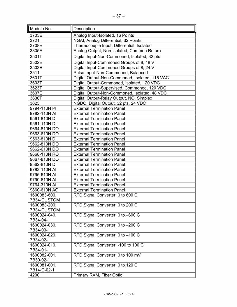
– 37 –
Module No. Description
3703E Analog Input-Isolated, 16 Points 3721 NGAI, Analog Differential, 32 Points 3708E Thermocouple Input, Differential, Isolated 3805E Analog Output, Non-isolated, Common Return 3501T Digital Input-Non-Commoned, Isolated, 32 pts 3502E Digital Input-Commoned Groups of 8, 48 V 3503E Digital Input-Commoned Groups of 8, 24 V 3511 Pulse Input-Non-Commoned, Balanced 3601T Digital Output-Non-Commoned, Isolated, 115 VAC 3603T Digital Output-Commoned, Isolated, 120 VDC 3623T Digital Output-Supervised, Commoned, 120 VDC 3607E Digital Output-Non-Commoned, Isolated, 48 VDC 3636T Digital Output-Relay Output, NO, Simplex 3625 NGDO, Digital Output, 32 pts, 24 VDC 9794-110N PI External Termination Panel 9782-110N AI External Termination Panel 9561-810N DI External Termination Panel 9561-110N DI External Termination Panel 9664-810N DO External Termination Panel 9663-610N DO External Termination Panel 9563-810N DI External Termination Panel 9662-810N DO External Termination Panel 9662-610N DO External Termination Panel 9668-110N RO External Termination Panel 9667-810N DO External Termination Panel 9562-810N DI External Termination Panel 9783-110N AI External Termination Panel 9795-610N AI External Termination Panel 9790-610N AI External Termination Panel 9764-310N AI External Termination Panel 9860-610N AO External Termination Panel 1600083-600, 7B34-CUSTOM
RTD Signal Converter, 0 to 600 C
1600083-200, 7B34-CUSTOM
RTD Signal Converter, 0 to 200 C
1600024-040, 7B34-04-1
RTD Signal Converter, 0 to –600 C
1600024-030, 7B34-03-1
RTD Signal Converter, 0 to –200 C
1600024-020, 7B34-02-1
RTD Signal Converter, 0 to –100 C
1600024-010, 7B34-01-1
RTD Signal Converter, -100 to 100 C
1600082-001, 7B30-02-1
RTD Signal Converter, 0 to 100 mV
1600081-001, 7B14-C-02-1
RTD Signal Converter, 0 to 120 C
4200 Primary RXM, Fiber Optic

– 38 –
Module No. Description
4201 Remote RXM, Fiber Optic Note: Module numbers correctly show the part number used for qualification without the “N” nuclear qualified designator (e.g., 8110N) and in no way implies that the commercial equivalents (e.g., 8110) are interchangeable with the nuclear qualified parts listed in Table 1 of this document. 3.3.1 TEST SYSTEM CONFIGURATION
The Tricon Under Test (TUT) consisted of four Tricon chassis populated with selected input, output, communication, and power supply modules as noted in the table above. The TUT also included external termination assemblies provided for connection of field wiring to the Tricon input and output modules. The System Description (Reference 22) shows the general arrangement and interconnection of the Tricon Test Specimen chassis and provides an overview and description of the test specimen and test system. Analog and digital inputs to the test specimen were generated using a two-chassis simulator Tricon system. This system was configured with a simulator application program that was used to create a variety of static and dynamic input signals. Other test equipment was used to provide additional AIs to the TUT. Analog and digital outputs from the TUT were monitored with indicator lights and a PC-based data acquisition system (DAS). The DAS also monitored analog and digital inputs to the TUT. Data was recorded and analyzed by the DAS during the various tests to verify proper operation of individual input and output points. Two PCs running the TriStation software were used to communicate with and monitor the status of the TUT and the simulator Tricon system. The TriStation software used for this purpose was TriStation 1131, which is Windows based software. During each of the qualification tests, operation of the TUT was monitored and recorded by the DAS. The recorded data was evaluated in detail before, during, and after the test period. The data evaluation considered operation (per the Test Specimen Application Program (TSAP)) of at least one input or output point on each I/O module installed in the TUT, and operation of all peripheral communication interfaces including the Simulator Tricon Peer-to-Peer and MODBUS interfaces. The TUT multi-channel test configuration and the overall test strategy are documented in the “Master Test Plan,” IOM Document No. 9600164-500, Revision 5 (Reference 23). The TSAP for the Tricon V10 was developed under IOM’s Appendix B program and was used in the performance of qualification testing including pre- and post-qualification operational and prudency tests. The NRC staff concluded that the TSAP met the requirements of EPRI TR-107330, Section 6.2.2, based on its review of the “Test Specimen Application Program Software Validation and Verification Plan,” IOM Document No. 9600164-513 (Reference 39), “Test Specimen Application Program Software Validation and Verification Report,” IOM Document No. 9600164-536 (Reference 40), “Independent Tricon V10 Equipment Qualification Assessment,” Section 2.0 (Reference 25), and Appendix 2 of the “Master Test Plan” (Reference 23). The NRC staff notes that multi-mode fiber optic cables and any interconnecting hardware used to connect primary and remote RXMs are not included in the qualification program. Licensees using RXM configurations are required to supply this equipment and it is an ASAI to verify that these user supplied components meet IOM specifications and are qualified for the specific environmental conditions.

– 39 –
3.3.2 PRE-QUALIFICATION TESTING
IOM performed pre-qualification testing to (1) confirm that the Tricon PLC test system was properly configured and operational, (2) provide baseline performance data for comparison with data obtained during and after qualification testing, and (3) validate the test procedures. Pre-qualification testing included the following assessments:
• The system setup and checkout test documented proper configuration and operation of the Tricon PLC test system, including hardware, software, input and output simulators; test and measurement equipment; and interconnecting cabling.
• The operability test to establish baseline performance included tests for analog module accuracy, system response time, operation of discrete inputs and outputs, performance of timer functions, failover tests (associated with the failure of redundant components), loss of power, detection of failure to complete a scan, power interruption, and power quality tolerance.
• Prudency testing demonstrated the ability of the Tricon PLC system to operate within specifications under dynamic conditions. The prudency test included a burst of events test, a serial port receiver failure test, and a serial port noise test.
The pre-qualification testing was designed to follow the requirements of Section 5.2 of EPRI TR-107330 by establishing baseline conditions for the TUT that followed the published specifications and by verifying system configuration/setup and proper operation. This testing exposes the TUT to various normal and abnormal conditions of input/output operation and power source variations. This testing includes operability testing and prudency testing as specified in EPRI TR-107330, Sections 5.3, 5.4, 5.5, and 6.4.3. All testing prerequisites were met, although an engineering change order was required to address failures of two AO points (3805 AO Module). These points were subsequently successfully retested. The system setup and checkout test documented the proper configuration and operation of the TUT. The establishment of the baseline performance was acceptable and the results of the prudency testing showed the TUT was able to operate within specifications under dynamic conditions. The pre-qualification testing and the ensuing results meet the guidance presented in EPRI TR-107330, Section 5. IOM described several exceptions during the prequalification tests:
• PLC library Software Objects Testing – IOM did not perform software object testing as part of the pre-qualification test. IOM Document No. 9600164-535, “Software Qualification Report,” Sections 5.2 and 7.3 (Reference 41) described the credited testing by independent reviewer TÜV Rheinland which includes source code reviews based on documented requirements as well as validation testing. IOM independently verified each incremental revision of the product in this manner. The NRC staff concludes that the collective independent review and testing performed by TÜV Rheinland since the NRC staff evaluated Tricon V9.5.3 is appropriately credited.
• Burn-in Testing – IOM did not perform separate burn-in tests as prescribed in EPRI TR-107330 Section 5.2F. The LTR justifies this exception by taking credit for routine burn-in testing that is performed as part of the manufacturing process for the Tricon PLC system hardware. The NRC staff determined that IOM manufacturing burn-in process satisfied EPRI 107330 criteria in Section 4.1.3.1 of the V9 safety evaluation (Reference 9).

– 40 –
• Response Time - EPRI TR-107330 Section 4.2.1.A gives a response time requirement of 100 msec based on a given list of test set requirements. The IOM test configuration required to adequately meet other qualification testing requirements does not conform to the given response time test set criteria. The Tricon response time is dependent on specific system configuration and is calculated for each application. The acceptance criteria used for NRC staff’s evaluation is based on the calculated maximum response times given in IOM Document No. 9600164-731 Section 4.0 (Reference 43). Tested maximum response times (which met the calculated response times) were given in IOM Document No. 9600164-566, Section 6.0 (Reference 44); DI to DO loop 83.0 msec, AI to DO loop 119.0 msec, AI to AO loop 126.5 msec. Similar exception was approved by the NRC staff in Section 4.3.5 of the V9 SE (Reference 9).
Further details of the testing can be found in the following IOM documents:
Document Title IOM Document No. Set-up & Checkout Test Procedure 9600164-502 Operability Test Procedure 9600164-503 Prudency Test Procedure 9600164-504 TSAP SW Requirements Spec 9600164-517 TSAP SW Design Description 9600164-518 TSAP V&V Plan 9600164-513 TSAP Final V&V Report 9600164-536 Pre-Qualification Operability Test Report 9600164-560 Pre-Qualification Prudency Test Report 9600164-570
The NRC staff concluded that the pre-qualification testing met the intent of EPRI TR-107330. 3.3.3 RADIATION WITHSTAND TEST
Radiation testing of the Tricon was performed in accordance with the requirements of EPRI TR-107330 Sections 4.3.6.1 and 4.3.6.2 and IEEE Std 381-1977 at the University of Massachusetts, Lowell. The Tricon met all applicable performance requirements after application of the radiation test conditions. The radiation test included the withstand capability of the Tricon to a rapid dose of radiation that would be normally provided as a long term, low level 1000 RAD gamma dose integrated over a 40 year period in a mild environment. The radiation test acceptance criteria are as given below based on Appendix 4 of the Master Test Plan (Reference 23) and EPRI TR-107330, Section 4.3.6:
• The TUT shall not exhibit any exterior damage or degradation as a result of gamma radiation exposure based on visual examinations performed following Radiation Exposure Testing. Such conditions include, but are not limited to, blistered protective coatings, deformation, crazing or discoloration of plastic components, and deformed or visually embrittled cable insulation.
• The TUT shall pass the post radiation operability test following the completion of radiation exposure testing.
• The TUT shall pass the post radiation prudency test following the completion of radiation exposure testing.
Radiation exposure testing of the TUT was performed on December 13 and 14, 2006, at the University of Massachusetts, Lowell. The testing complied with the specific requirements of EPRI TR-107330, Section 4.3.6, and the general requirements of IEEE Std 381-1977. TUT

– 41 –
components were exposed to Co60 gamma radiation doses of 1000 RAD plus margin in exposures just over 2 hours in duration. Due to limitations of the source and the size of the overall test set, components were exposed separately. Each component received the required dose plus margin. Post testing inspection revealed no visible effects from the exposure. Operability and prudency test results shows that exposure to the radiation test conditions had no adverse effect on the TUT. The NRC staff reviewed the “Radiation Test Report,” IOM Document No. 9600164-533 (Reference 45), and determined that the level of exposure is consistent with installation in a mild environment, as specified in Section 4.3.6 of EPRI TR-107330 and IEEE Std 381-1977. On the basis of these tests, the NRC staff concludes that the Tricon V10 PLC system hardware is qualified to the radiation exposure levels specified in the EPRI TR and the IEEE standard. However, before installing plant-specific Tricon PLC system equipment, licensees will need to verify that the expected radiation exposure for the equipment is enveloped by the radiation withstand capacity of the Tricon PLC system equipment. This is an ASIA. 3.3.4 TEMPERATURE AND HUMIDITY TESTING
Environmental qualification testing of the TUT was performed in accordance with EPRI TR-107330, Sections 4.3.6 and 6.3.3, and IEEE Std 381-1977 and includes the following:
• The test PLC shall meet its performance requirements during and following exposure to abnormal environmental conditions of 40 °F to 140 °F and 5 percent to 95 percent relative humidity (RH) (non-condensing) according to a time varying profile (see Figure 4-4 of the EPRI TR-107330).
• Environmental testing shall be performed with the power supply sources set to values that maximize heat dissipation in the test PLC.
• Power supplies shall be loaded such that nominal current draws at nominal power supply output voltages are equal to the power supply rating.
• The test PLC shall be powered with its TSAP operating during environmental testing, with 1/2 of the discrete and relay outputs ON and loaded to their rated current. In addition, all AOs shall be set to between 1/2 and 2/3 of full scale. Section 4.3.6.2 of EPRI TR-107330 requires that the generic PLC meet its performance requirements over abnormal environmental conditions of 40 °F to 120 °F and 10 percent to 95 percent RH (non-condensing). Section 4.3.6.3 of EPRI TR-107330 requires that the test PLC operate for the environmental (temperature and humidity) withstand profile given in Figure 4-4 of the TR. The profile includes a beginning ramp-up period (unspecified in duration) from ambient to 140 °F and 90 percent RH (non-condensing). These conditions are held for 48 hours minimum, after which the Operability and Prudency tests are run. Conditions are then ramped down over a four hour minimum period to 40 °F and 5 percent relative humidity. These conditions are held for 8 hours minimum, after which a second Operability test is run. Conditions are then ramped up over a four hour minimum period to ambient temperature and relative humidity. The equipment is stabilized at ambient conditions, after which a final Operability test is run. Section 6.3.3 of EPRI TR- 107330 requires that Environmental Testing be performed with margins of 5 F and 5 percent applied to the temperature and humidity values given above.
The environmental test acceptance criteria are as given below based on Appendix 5 of the Master Test Plan (Reference 23), and EPRI TR-107330, Section 4.3.6:

– 42 –
• The TUT shall operate as intended during and after exposure to the environmental test conditions. Evaluation of normal operating performance data (inputs, outputs and diagnostic indicators) collected during testing shall demonstrate operation as intended.
• The TUT shall pass the Operability Test following at least 48 hours of operation at high temperature and humidity, following at least 8 hours of operation at low temperature and humidity and upon completion of the test.
• The TUT shall pass the Prudency Test following at least 48 hours of operation at high temperature and humidity.
Environmental testing of the TUT was performed on December 13, 2006, through January 15, 2007, at National Technical Systems in Boxborough, Massachusetts. Results of the testing are described in “Environmental Test Report,” IOM Document No. 9600164-525 (Reference 46). As described in the test report and depicted below in Figure 3.3.4-1, the actual sequence of testing was as follows:
• Installation in the National Technical Systems environmental test chamber, and stabilization at ambient temperature and relative humidity conditions.
• Ramp-up to 140 °F and 95 percent RH over a 4 hour period. • Hold at 140 °F and 95 percent RH for a 1 hour period. • Troubleshoot test system for a 1 hour period. • Hold at 140 °F and 95 percent RH for a 47 hour period. • High temperature Operability Test performed over an 8 hour period. • High temperature Prudency Test performed over a 2.5 hour period. • Attempt ramp-down to 35 °F and 5 percent RH over a 17 hour period. • Return to ambient and perform repairs of test chamber over a 100 hour period. • Ramp-down to 35 °F and 5 percent RH over a 6 hour period. • Hold at 35 °F and 5 percent RH for an 8 hour period. • Low temperature Operability Test performed over a 9 hour period • Ramp-up to ambient temperature and RH over a 5 hour period. • Hold at ambient temperature and RH for a 2 hour period. • Ambient temperature Operability Test performed over a 13 hour period.
The environmental chamber experienced a mechanical failure during the transition from high temperature, high humidity conditions to low temperature conditions. The transition was originally planned to occur in no less than four hours as prescribed by requirements. As a result of the chamber failure, the TUT was returned to ambient conditions for approximately 100 hours. On repair of the chamber, the transition to low temperature was continued and required approximately six hours. The NRC staff reviewed the details of the test equipment failure as described in the “Environmental Test Report,” IOM Document No. 9600164-525 (Reference 46) and concluded that the minimum four hour transition time is not a challenging temperature transition and because the equipment under test was not disturbed, the delay at ambient for test chamber repairs does not significantly impact the outcome of the test. The separate manufacturing burn-in performed on all production Tricon equipment, including the equipment used for this test, also provides support that the equipment performs as designed. IOM recorded two internal diagnostic faults during the high temperature hold period. As described in the Environmental Test Report (Reference 46), the Model 3708E thermocouple input module reported a diagnostic fault message during the high temperature hold period. The fault cleared automatically during ramp-down from the high temperature hold period. The normal operating performance data recorded during Environmental Testing showed that the affected points of the module continued to operate correctly in the presence of the fault. The

– 43 –
high temperature Operability Test analog I/O accuracy data shows that the points of the module continued to meet the accuracy specifications in the presence of the fault. Model 3623T 120 VDC digital output module also reported a diagnostic fault message during the high temperature hold period. The detected fault did not impact the proper operation of the TUT during testing. IOM performed operability and prudency tests both during and after the environmental test. No adverse effect on the TUT performance were reported. The NRC staff reviewed the “Environmental Test Report,” IOM Document No. 9600164-525 (Reference 46) and determined that the Tricon V10 met the requirements of EPRI TR-107330, Sections 4.3.6 and 6.3.3, and IEEE Std 381-1977.
Figure 3.3.4-1 – Environmental Test Applied Temperature and Humidity Profile
3.3.5 SEISMIC WITHSTAND TESTING
To demonstrate that the Tricon V10 meets the requirements for Seismic Category 1 Safety System, IOM subjected the TUT to seismic simulation testing during Safe Shutdown Earthquake (SSE) and Operating Basis Earthquakes (OBEs). Seismic Testing conforms to the requirements of IEEE Std 344-1987 and Sections 4.3.9 and 6.3.4 of EPRI TR-107330. In addition to demonstrating the performance requirements under the specified conditions, a resonance search procedure was also conducted. Attachment 6 of the Master Test Plan (Reference 23) describes the seismic test plan. The Seismic Test Procedure is IOM Document No. 9600164-507. For seismic testing, IOM performed a resonance search followed by five simulated OBEs and one simulated SSE at 9.75 g’s and 14 g’s respectively, based on 5 percent damping. The simulation vibrations are required to be applied tri-axially (in three orthogonal directions), with random frequency content. Seismic testing was performed at NTS facilities in Acton, Massachusetts. NTS personnel provided testing services and established test conditions as specified in the TR-107330 specification, including documenting the mounting of the TUT to the seismic test apparatus.

– 44 –
The TSAP was loaded and operating during seismic testing, exercising all TUT components, and supporting automated test data collection. The resulting data documented TUT operation in accordance with the applications depicted in the project functional diagrams. Data also supports monitoring performance of the module 3636T electromechanical relay contacts during testing. Additionally, operability testing was conducted at the completion of the seismic tests. The seismic test acceptance criteria are as given below based on Appendix 6 of the Master Test Plan, Reference 23, and EPRI TR-107330, Section 4.3.9:
• The TUT shall operate as intended during and after application of the OBE and SSE vibrations. Evaluation of normal operating performance data (inputs, outputs, and diagnostic indicators) shall demonstrate operation as intended.
• During and after application of the OBE and SSE vibrations, all connections on the TUT shall remain intact, all modules installed in the TUT shall remain fully inserted, and no functional or non-functional parts of the TUT shall fall off.
• The operation of the chassis power supply normally open alarm relay contacts and the Model 3636T electromechanical relay module output contacts shall be monitored during application of the OBE and SSE vibrations. The relay contacts shall change state in accordance with the TSAP. Any spurious change of state of the relay contacts shall not exceed 2 msec in duration. Any spurious change of state of the power supply alarm relay contacts from open to closed shall not exceed 2 msec in duration.
• The TUT shall pass the Operability Test following completion of the seismic testing. The TUT was populated with selected main processor, input, output, communication, chassis interface, and chassis power supply modules. The TUT power was supplied by variable AC and DC power sources configured as described in the “Seismic Test Procedure,” IOM Document No. 9600164-507. During seismic testing, both power supply modules in each chassis were energized. Chassis 1 and 2 each included a 120 VAC chassis power supply module and a 24 VDC chassis power supply module. Chassis 3 and 4 each included a 120 VAC chassis power supply module and a 230 VAC chassis power supply module. However, to accommodate seismic testing at minimum external power supply voltages, the test system power supply configuration was temporarily modified for testing of TUT Chassis 3 and 4 to allow the voltages to the 120 VAC and 230 VAC chassis power supply modules to be set independently. The power supplies to the 120 VAC and 230 VAC chassis power supply modules were set to the minimum allowable operating voltage as specified by the manufacturer. The TUT chassis was mounted to the seismic test table in accordance with mounting details provided on IOM Drawing No. 9600164-102. The seismic test mounting simulated a typical 19-inch rack mount configuration using standard Tricon V10 front and rear chassis mounting brackets and fastener hardware, and standard Tricon V10 external termination assembly mounting plates. Details on the equipment arrangement for seismic testing are provided in the IOM Seismic Test Report (Reference 27). The TSAP was loaded and operating during seismic testing, exercising all TUT components, and supporting automated test data collection. The TSAP revision used was “V10_TSAPREV_0.” During seismic testing, the relay output configuration did not meet the requirements of Section 6.3.4.2 of EPRI TR-107330. However, a large number of relay output points (32 total) were monitored, which IOM considered a significantly representative number of relay output points, and thus, met the intent of the TR-107330 requirement to have points in both the ON and OFF positions throughout testing.

– 45 –
The Tricon V10 did not fully comply with the seismic requirements. The seismic table achieved the EPRI TR-107330 OBE and SSE Required Response Spectrum test levels throughout most of the required frequency range. Test equipment limitations resulted in a reduced response spectrum during the performance of seismic testing. Specifically, in the low frequency region (below 6 Hz), limitations of the table velocity and displacement prevented achieving the full EPRI TR-107330 Required Response Spectrums. The as-tested spectrum is depicted in the LTR and shown below. Results of the testing are described in the Seismic Test Report, Reference 27. Resonance search testing demonstrated that the simulated mounting configuration was stiff enough so that there were no resonances below 100 Hz. Specifically, for seismic testing, the weight loadings of the four TUT chassis were varied from light (chassis 3) to moderate (chassis 2) to heavy (chassis 1 and 4) to demonstrate seismic vibration susceptibility for various chassis loadings. Table 5-1 of EPRI TR-107330 requires that Operability and Prudency Testing be performed during SSE. Because the duration of each OBE/SSE test (approximately 30 seconds) did not support full Operability or Prudency Testing, IOM did not perform the Operability and Prudency Tests during the Seismic Tests. Data collected during and after each OBE and SSE test demonstrated that the TUT operated as intended throughout the testing. Table 5-1 and Section 6.3.4.3 of EPRI TR-107330 require post-seismic Operability Testing to assess the impact of exposure to the OBE and SSE vibrations on the operability of the test specimen. Test results provided in the Seismic Test Report showed that exposure to the OBE and SSE vibrations had no adverse effects on the TUT performance. The TUT was visually inspected for damage or degradation following each OBE and SSE test. During inspection of Chassis 1 and 2, after OBE test No. 3, IOM had to address problems with the interface cable connection. A cable restraint at the tie-down point was modified, retesting was not required. To avoid this problem in a plant-specific installation, IOM’s field installation guidance will describe how to secure this cable. In addition, there were other cases of physical damage and degradation in TUT Chassis 1 and 2 during OBE tests, but these were corrected, and the equipment was successfully retested. During setup/checkout testing, IOM determined that an interposing relay would be required to monitor the chassis alarm contacts as a result of the test setup. This configuration had a potential to mask contact chatter during the test. Therefore, the TUT chassis alarm relays were not seismically qualified as part of seismic testing. The NRC staff determined that the tested Tricon V10 system equipment is qualified to the tested triaxial seismic simulator table limits shown in Figures 3.3.5-1 through 3.3.5-3 below, with the exception of the low frequency region (below 6 Hz). For this reason the NRC staff finds that the Tricon V10 system did not fully meet the requirements of EPRI TR-107330 for seismic requirements, and before using Tricon V10 system equipment in SR systems in a NPP, licensees must determine that the plant-specific seismic requirements are enveloped by the capabilities of the Tricon V10 system. This determination and the suitability of the Tricon V10 system for a particular plant and application is the responsibility of the licensee.

– 46 –
Figure 3.3.5-1 – OBE Test Acceleration

– 47 –
Figure 3.3.5-2 – SSE Test Acceleration

– 48 –
Figure 3.3.5-3 – Horizontal and Vertical Seismic Withstand Response Spectrum
3.3.6 EMI/RFI WITHSTAND TESTING
EPRI TR-107330 includes electromagnetic compatibility (EMC) testing as part of the overall program to generically qualify a PLC for SR application in a NPP. Specifically, criteria for electromagnetic emissions, EMI susceptibility, electrostatic discharge withstand, power surge withstand, and isolation capability are given in Sections 4.3, “Hardware Requirements,” and 4.6, “Electrical,” of the guide while the qualification approach is specified in Section 6.3, “Qualification Tests and Analysis Requirements.” The methods for implementing EMC testing are provided by other referenced guides, as discussed below. RG 1.180, “Guidelines for Evaluating Electromagnetic and Radio-Frequency Interference in Safety-Related Instrumentation and Control Systems,” endorses MIL-STD-461E, “Requirements for the Control of Electromagnetic Interference Characteristics of Subsystems and Equipment,” and IEC 61000 series standards for the evaluation of the impact of EMI, radio-frequency interference (RFI) and power surges on SR I&C systems, and to characterize the electromagnetic (EM) emissions from the I&C systems.

– 49 –
EPRI TR-102323, “Guideline for Electromagnetic Interference Testing in Power Plants,” provides alternatives to performing site-specific EMI/RFI surveys to qualify digital safety I&C equipment for a plant’s EM environment. In an SE issued in 1996, the NRC staff concluded that the recommendations and guidelines in EPRI TR-102323 provide an adequate method for qualifying digital l&C equipment for a NPP’s EM environment without the need for plant-specific EMI/RFI surveys if the plant-specific EM environment is confirmed to be similar to that identified in EPRI TR-102323. EMI and RFI testing was performed in accordance with EPRI TR-102323, Revision 1, Section 6.3.2 of EPRI TR-107330, and RG 1.180, Revision 1, to demonstrate the suitability of the Tricon V10 platform for qualification as a SR device with respect to EMI/RFI emissions and susceptibility. All of the TUT components were subjected to EMI/RFI testing as required. EMI/RFI testing of the TUT was performed inside open frame racks. The testing was performed in accordance with EPRI TR-107330 and RG 1.180 test method requirements. The specific tests conducted include the following MIL-STD-461E and IEC test methods: The following EMI/RFI emissions tests were performed:
• MIL-STD-461E, Test Method CE101, Conducted Emissions, 30 Hz to 10 kHz • MIL-STD-461E, Test Method CE102, Conducted Emissions, 10 kHz to 2 MHz • MIL-STD-461E, Test Method RE101, Radiated Emissions, 30 Hz to 100 kHz • MIL-STD-461E, Test Method RE102, Radiated Emissions, 2 MHz to 1 GHz
The following EMI/RFI susceptibility tests were performed:
• IEC 61000-4-3, Radiated Susceptibility, 26 MHz to 1 GHz • IEC 61000-4-6, Conducted Susceptibility, 150 kHz to 80 MHz • IEC 61000-4-8, Radiated Susceptibility, Power Line Frequency Magnetic Field • IEC 61000-4-9, Radiated Susceptibility, Pulsed Magnetic Field • IEC 61000-4-10, Radiated Susceptibility, Damped Oscillatory Magnetic Field • IEC 61000-4-13, Conducted Susceptibility, Harmonics and Interharmonics • IEC 61000-4-16, Conducted Susceptibility, Common-Mode Disturbances
The EMI/RFI test acceptance criteria are as follows, based on Appendix 7 of the “Master Test Plan,” IOM Document No. 9600164-500 (Reference 23), and EPRI TR-107330, Section 4.3.7:
• The TUT shall meet allowable equipment emission limits as specified in RG 1.180, Revision 1, for conducted and radiated emissions.
• The TUT shall operate as intended during and after application of the EMI/RFI test levels specified in RG 1.180 for conducted and radiated susceptibility.
In addition, evaluation of normal operating performance data (inputs, outputs, and diagnostic indicators) shall demonstrate operation as intended, including the following specific operational performance criteria from Section 4.3.7 of EPRI TR-107330:
• The main processors and coprocessors shall continue to function • The transfer of I/O data shall not be interrupted • The emissions shall not cause the discrete I/O to change state • Analog I/O levels shall not vary more than 3 percent

– 50 –
EMI/RFI testing of the Tricon V10 was performed from February 17 through April 16, 2007, at National Technical Systems in Boxboro, Massachusetts. The TUT was installed in the EMI/RFI chamber in open-frame racks as required by the EPRI TR-107330. Wiring connections and grounding were in accordance with the manufacturer’s recommendations. Additional EMI/RFI protective and mitigating devices such as power or I/O line filters, enclosed cabinets, and extra cable shielding were not used so that the specific emissions and susceptibilities of the equipment could be determined. During EMI/RFI testing, the TUT was powered with TSAP operating. The AC and DC power sources to the TUT chassis power supplies were set at nominal source voltage and frequency conditions. In order to minimize transmission of outside EMI/RFI sources into the EMI/RFI test chamber, all power, signal, and communications cables entering the EMI/RFI test chamber were passed through filters located in the chamber walls. Because the number of pass-through filters was limited, only one circuit per I/O module was connected. The results of the EMI/RFI testing on the TUT, as documented in “EMI/RFI Test Report,” IOM Document No. 9600164-527 (Reference 26), are as follows: The TUT does not fully comply with the allowable equipment emissions levels defined in RG 1.180, Revision 1, for MIL-STD-461E, CE101, and CE102 testing. MIL-STD-461E, Test Method CE101: Conducted Emissions, 30 Hz to 10 kHz
• 120 VAC Chassis Power Supply Line Lead. Conducted emission exceeded at: 179.7 Hz by 11.2 dBμA 538.8 Hz by 8.9 dBμA 299.8 Hz by 13.8 dBμA 659.7 Hz by 2.1 dBμA 419.7 Hz by 13.0 dBμA 899.6 Hz by 1.5 dBμA
• 120 VAC Chassis Power Supply Neutral Lead. Conducted emission exceeded at:
179.9 Hz by 11.0 dBμA 539.7 Hz by 9.6 dBμA 299.8 Hz by 14.9 dBμA 659.9 Hz by 2.8 dBμA 419.3 Hz by 13.1 dBμA
• 230 VAC Chassis Power Supply Line Lead. Conducted emission exceeded at: 179.9 Hz by 4.0 dBμA 539.7 Hz by 7.6 dBμA 299.8 Hz by 8.3 dBμA 659.7 Hz by 6.0 dBμA 419.7 Hz by 8.7 dBμA 779.6 Hz by 1.7 dBμA
• 230 VAC Chassis Power Supply Neutral Lead. Conducted emission exceeded at:
179.9 Hz by 3.8 dBμA 539.7 Hz by 7.5 dBμA 299.8 Hz by 8.2 dBμA 659.7 Hz by 5.9 dBμA 419.7 Hz by 8.6 dBμA 779.6 Hz by 1.6 dBμA
MIL-STD-461E, Test Method CE102: Conducted Emissions, 10 kHz to 2 MHz
• 120 VAC Chassis Power Supply Line Lead. Conducted emissions exceeded at: 50.0 kHz by 1.5 dBμA

– 51 –
The TUT discrete and analog I/O hardware, which does not fully comply with the minimum susceptibility thresholds required by RG 1.180, Revision 1, for the EMI/RFI susceptibility tests as listed below: IEC 61000-4-3 Testing: Radiated Susceptibility, 26 MHz to 1 GHz
• RTD Signal Conditioning Module 1600083-600 • RTD Signal Conditioning Module 1600083-200 • RTD Signal Conditioning Module 1600024-030 • RTD Signal Conditioning Module 1600024-020
IEC 61000-4-6 Testing: Conducted Susceptibility, 150 kHz to 80 MHz
• RTD Signal Conditioning Module 1600081-001 • Digital Output Module 3601T (115 VAC) with ETA 9663-610N
IEC 61000-4-10 Testing: Radiated Susceptibility, Damped Oscillatory Magnetic Field
• Due to test execution anomalies, the results of this testing were determined not to be valid. Therefore, compliance with IEC 61000-4-10 is indeterminate.
The NRC staff reviewed the “EMI/RFI Test Report,” IOM Document No. 9600164-527 (Reference 26), and determined that the tested Tricon V10 system met the EMI/RFI test acceptance criteria discussed above and is qualified up to the tested limits described above, with the exceptions as noted for the 8310 High Density Power Module (120VAC), 8312 High Density Power Module (230VAC), RTD Conditioning Modules 1600083-600, 1600083-200, 1600024-020, 1600024-030, 1600081-001, Digital Output Module 3601T (115VAC) with ETA 9663-610N, and the IEC 61000-4-10 testing. Given the exceptions noted above, the NRC staff determined that the Tricon V10 PLC system did not fully meet the guidance of RG 1.180, Revision 1, for conducted or radiated emissions or susceptibility. Before using the Tricon V10 system equipment in SR systems in a nuclear power plant, licensees must determine that the plant-specific EMI requirements are enveloped by the capabilities of the Tricon V10 system as approved in this SE. This determination and the suitability of the Tricon V10 system for a particular plant and application is the responsibility of the licensee. 3.3.6.1 ELECTRICAL FAST TRANSIENT
RG 1.180, Revision 1, Section 5.3, requires that the PLC under qualification be tested for electrical fast transient (EFT) susceptibility in accordance with the requirements of IEC 61000-4-4. RG 1.180, Sections 5.3 and 4.2, include the requirements for EFT testing of the AC and DC power supplies and signal leads respectively. EFT testing of the TUT is described in the “EFT Test Procedure,” IOM Document No. 9600164-514. The TUT was subjected to the following EFT tests:
• 120 VAC Chassis Power Supplies: ± 0.5 kV, ± 1.0 kV, ± 1.5 kV and ± 2.0 kV • 230 VAC Chassis Power Supplies: ± 0.5 kV, ± 1.0 kV, ± 1.5 kV and ± 2.0 kV • 24 VDC Chassis Power Supplies: ± 0.5 kV, ± 1.0 kV, ± 1.5 kV and ± 2.0 kV • Peripheral Communications Cables: ± 0.5 kV and ± 1.0 kV • ETA Input Power Wires: ± 0.5 kV and ± 1.0 kV • Analog Input/Output Wires: ± 0.5 kV and ± 1.0 kV

– 52 –
• RTD /T/C and Pulse Input Wires: ± 0.5 kV and ± 1.0 kV • Discrete Input/Output Wires: ± 0.5 kV and ± 1.0 kV
The EFT test acceptance criteria were as follows, based on Appendix 8 of the Master Test Plan (Reference 23) and EPRI TR-107330, Section 4.3.7:
• Applying the EFT Test voltages to the specified TUT interfaces will not damage any other module or device in the TUT, or cause disruption of the operation of the backplane signals or any other data acquisition signals.
• The TUT shall operate as intended during and after application of the IEC 61000-4-4 EFT test levels specified in Sections 4.2 and 5.3 of RG 1.180, Revision 1, for low exposure applications. Specifically: o IEC 61000-4-4: Power Leads, Level 3 Test Voltage Level: 2 kV max. o IEC 61000-4-4: Signal Leads, Level 3 Test Voltage Level: 1 kV max.
• Evaluation of normal operating performance data (inputs, outputs, and diagnostic indicators) shall demonstrate operation as intended, including the following specific operational performance from Section 4.3.7 of EPRI TR-107330: o The main processors shall continue to function. o The transfer of I/O data shall not be interrupted. o The applied EFT disturbances shall not cause the discrete I/O to change state. o Analog I/O levels shall not vary more than 3 percent (of full scale).
EFT testing of the TUT was performed from March 26 through 28, 2007, at National Technical Systems in Boxborough, Massachusetts. During EFT testing, the TUT was powered with the TSAP operating. The AC and DC power sources to the TUT chassis power supplies were set at nominal source voltage and frequency conditions. The arrangement and grounding of the system during EFT testing was as described for the EMI/RFI tests. During EFT testing, operation of the TUT was monitored by the DAS. The recorded data was evaluated in detail before, during, and after each test to verify normal operation of the system and all peripheral communication interfaces. Results of the EFT testing are documented in the EFT Test Report. Data collected during and after each voltage test demonstrate that the TUT operated as intended throughout the testing. IOM concluded the following from the EFT testing:
• EFT Testing of the TUT was performed in accordance with the applicable requirements of RG 1.180, Revision 1, and IEC 41000-4-4. The following EFT tests were performed: • 120 VAC Chassis Power Supplies: ± 0.5 kV, ± 1.0 kV, ± 1.5 kV and ± 2.0 kV • 230 VAC Chassis Power Supplies: ± 0.5 kV, ± 1.0 kV, ± 1.5 kV and ± 2.0 kV • 24VDC Chassis Power Supplies: ± 0.5 kV, ± 1.0 kV, ± 1.5 kV and ± 2.0 kV • Peripheral Communications Cables: ± 0.5 kV and ± 1.0 kV • ETA Input Power Wires: ± 0.5 kV and ± 1.0 kV • Analog Input/Output Wires: ± 0.5 kV and ± 1.0 kV • RTD, /T/C and Pulse Input Wires: ± 0.5 kV and ± 1.0 kV • Discrete Input/Output Wires: ± 0.5 kV and ± 1.0 kV
• The TUT met all applicable operational and performance requirements during and after each application of the EFT Tests voltages.
• The EFT Test results demonstrate that the Tricon V10 PLC will not experience operational failures or susceptibilities due to exposure to repetitive electrical fast transients on the power and signal input/output leads. The specific Tricon hardware

– 53 –
which was tested (chassis, power supplies, modules, external termination assemblies, and interconnecting cabling) is identified in the project Master Configuration List.
The NRC staff reviewed the “Electrical Fast Transient Test Report,” IOM Document No. 9600164-521, Revision 1 (Reference 53), and determined that the Tricon V10 exhibits acceptable performance against electrical fast transients as addressed in RG 1.180, Revision 1. 3.3.7 SURGE WITHSTAND TESTING
EPRI TR-107330, Section 4.6.2, requires that surge withstand testing of the PLC be conducted in accordance the requirements of EPRI TR-102323. RG 1.180, Revision 1, provides an NRC approved alternative to the Surge Withstand Testing specified in EPRI TR-102323. Surge Withstand Testing of the TUT AC power supplies was performed in accordance with IEC 61000-4-5 and IEC 61000-4-12 requirements. Surge withstand testing is described in the “Surge Withstand Test Procedure,” IOM Document No. 9600164-508. The TUT chassis power supplies and signal lines were subjected to the following surge tests:
• IEC 61000-4-5 Combination Wave: ± 2.0 kV (common mode and differential) • 120 VAC and 230 VAC Chassis Power Supplies • 24 VDC Chassis Power Supplies,
• IEC 61000-4-12 Ring Wave: ± 2.0 kV (common mode), ± 1.0 kV (differential) • 120 VAC and 230 VAC Chassis Power Supplies, • 24 VDC Chassis Power Supplies,
• IEC 61000-4-12 Ring Wave: ± 1.0 kV (common mode), ± 0.5 kV (differential) • AC and DC Rated Discrete Input Modules • AC and DC Rated Discrete Output Modules • Analog Input and Output Modules (RTD, T/C, Pulse, mV and mA) • TCM Modules, MODBUS Serial Ports
• IEC 61000-4-5 Combination Wave: ± 1.0 kV (common mode), ± 0.5 kV (differential) • AC and DC Rated Discrete Input Modules • AC and DC Rated Discrete Output Modules • Analog Input and Output Modules (RTD, T/C, Pulse, mV and mA) • TCM Modules, MODBUS Serial Ports
The surge withstand test acceptance criteria were as follows, based on Appendix 8 of the Master Test Plan (Reference 23) and EPRI TR-107330, Section 4.6.2:
• Applying the surge test voltages specified in Tables 15 and 22 of RG 1.180, Revision 1, to the specified TUT test points shall not damage any other module or device in the TUT, or cause disruption of the operation of the TUT backplane signals or any other data acquisition signals that could result in a loss of the ability to generate a trip.
• Evaluation of normal operating performance data (inputs, outputs and diagnostic indicators) shall demonstrate satisfactory operation of the TUT during and after application of the surge test voltage. The data evaluations shall demonstrate that modules other than the one tested are not damaged and do not experience disruption of their operation.
• Per Section 6.3.5 of TR-107330, failures of one or more redundant devices are acceptable so long as the failures do not result in the inability of the TUT to operate as

– 54 –
intended. No faults or failures of redundant devices occurred during Surge Withstand Testing.
The surge withstand testing was performed from March 28 through April 13, 2007, at National Technical Systems in Boxborough, Massachusetts. Prior to the start of testing, all of the TUT modules (Main Processors (MPs), communication, and I/O) were removed and replaced with spare modules. This was done to protect the modules which had been through environmental, seismic, and EMI/RFI testing from damage that could occur during surge withstand testing, and preserve the condition of the original modules for final performance proof testing. During surge withstand testing, the TUT was powered with the TSAP operating. The AC and DC power sources to the TUT chassis power supplies were set at nominal source voltage and frequency conditions. The arrangement and grounding of the system during surge withstand testing was as described for the EMI/RFI tests. During surge withstand testing, operation of the TUT was monitored by the DAS. The recorded data was evaluated in detail before, during, and after each test to verify normal operation of the system and all peripheral communication interfaces. Results of the surge withstand testing are documented in the Surge Withstand Test Report. Data collected during and after each voltage tests demonstrate that the TUT operated as intended throughout the testing. IOM concluded the following based upon the testing:
1. Surge Withstand Testing of the TUT was performed in accordance with the applicable requirements of the IEC 61000-4-5 and IEC 61000-4-12 test methods. The following Surge Withstand tests were performed: • IEC 61000-4-5 Combination Wave: ± 2.0 kV
• 120 VAC and 230 VAC Chassis Power Supplies, - Line to Neutral - Line to AC Ground - Neutral to AC Ground - Line and Neutral to AC Ground
• 24 VDC Chassis Power Supplies, - High Side (+) to Low Side (-) - Low Side (-) to AC Ground
• IEC 61000-4-12 Ring Wave: ± 2.0 kV • 120 VAC and 230 VAC Chassis Power Supplies,
- Line to AC Ground - Neutral to AC Ground - Line and Neutral to AC Ground
• 24 VDC Chassis Power Supplies, - Low Side (-) to AC Ground
• IEC 61000-4-12 Ring Wave: ± 1.0 kV • 120 VAC and 230 VAC Chassis Power Supplies,
- Line to Neutral • 24 VDC Chassis Power Supplies,
- High Side (+) to Low Side (-) • IEC 61000-4-12 Ring Wave, IEC 61000-4-5 Combination Wave: ± 0.5 kV
• AC Rated Discrete Input Modules - One Point per Module

– 55 –
- Line to Neutral - Point ON and OFF
• AC Rated Discrete Output Modules - One Point per Module - Line to Neutral - Point ON and OFF
• IEC 61000-4-12 Ring Wave, IEC 61000-4-5 Combination Wave: ± 1.0 kV • AC Rated Discrete Input and Output Modules
- One Point per Module - Neutral to AC Ground - Point ON and OFF
• DC Rated Discrete Input and Output Modules - One Point per Module - Low Side (-) to AC Ground - Point ON and OFF
• Analog Input and Output Modules (RTD, T/C, Pulse, mV and mA) - One Point per Module - Shield to AC Ground
• TRICON Communication Modules (TCMs), MODBUS Serial Ports - One Port - Connector Shield to AC Ground
2. The TUT met all applicable operational and performance requirements during and after
each application of the Surge Withstand Test voltages.
3. The Surge Withstand Test results demonstrate that the Tricon V10 PLC will not experience operational failures or susceptibilities that could result in a loss of the ability to generate a trip due to exposure to Ring Wave and Combination Wave electrical surges to the components listed above. The specific Tricon hardware which was tested (chassis, power supplies, modules, external termination assemblies, and interconnecting cabling) is identified in the project Master Configuration List.
The NRC staff reviewed the “Surge Withstand Test Report,” IOM Document No. 9600164-528 (Reference 54), and determined that the Tricon V10 meets the surge withstand performance criteria in EPRI TR-107330, EPRI TR-102323, Revision 1, and RG 1.180, Revision 1. 3.3.8 ELECTROSTATIC DISCHARGE WITHSTAND TESTING
EPRI TR-107330, Section 4.3.8, requires that the PLC under qualification be tested for immunity to the ESD test levels specified in EPRI TR-102323-R1. ESD Testing of the TUT was performed in accordance with IEC 61000-4-2, using the test levels defined in EPRI TR-102323-R1, Appendix B, Section 3.5. ESD testing is described in the “ESD Test Procedure,” IOM Document No. 9600164-522. The TUT was subjected to the following ESD tests: ESD Direct Contact Discharges: ± 2 kV, ± 4 kV, ± 6 kV and ± 8 kV
• Chassis 1 Battery Cover (4 points) • Chassis 1 Control Keyswitch (1 point) • All ETA Cable Chassis Connectors, Top Thumbscrews (25 points) • All Chassis, Front Horizontal and Vertical Edges (32 points)

– 56 –
• Each Chassis Power Supply Module Type, Faceplate (3 points) • Each Chassis Power Supply Module Type, Top Thumbscrew (3 points) • Main Processor, TCM, RXM and I/O Modules, Top Thumbscrews (38 points) • Model 4352A TCM Module Serial 1 Port, Metal Cable Connector (1 point)
ESD Direct Air Discharges: ± 2 kV, ± 4 kV, ± 8 kV and ± 15 kV
• Model 4352A TCM Module Net 1 Port, Plastic Cable Connector (1 point) • Model 4352A TCM Module Net 2 Port, Plastic Cable Connector (1 point)
ESD Indirect Contact Discharges: ± 2 kV, ± 4 kV, ± 6 kV and ± 8 kV
• Horizontal Coupling Plane, Parallel to Chassis Bottom Faces (4 points) • Vertical Coupling Plane, Parallel to Chassis Front Faces (12 points) • Vertical Coupling Plane, Parallel to ETAs (4 points)
The ESD test acceptance criteria are as follows, based on Appendix 8 of the Master Test Plan, (Reference 23), and EPRI TR-107330, Sections 4.3.7 and 4.3.8:
• Applying the ESD Test voltages to the specified TUT interfaces will not damage any other module or device in the TUT, or cause disruption of the operation of the backplane signals or any other data acquisition signals.
• The TUT shall operate as intended during and after application of the IEC 61000-4-2 Level 4 ESD test levels specified in Appendix B, Section 3.5 of EPRI TR-102323-R1 and Section 5 of IEC 61000-4-2. Specifically:
IEC 61000-4-2: Air Discharges Test Voltage Level: ± 15 kV max. IEC 61000-4-2: Contact Discharges Test Voltage Level: ± 8 kV max.
• Evaluation of normal operating performance data (inputs, outputs and diagnostic indicators) shall demonstrate operation as intended, including the following specific operational performance from Section 4.3.7 of EPRI TR-107330:
• The main processors shall continue to function. • The transfer of I/O data shall not be interrupted. • Applied ESD disturbances shall not cause the discretes to change state. • Analog I/O levels shall not vary more than 3 percent (of full scale).
• Per Section 4.3.8 of EPRI TR-107330, failures of one or more redundant devices due to application of ESD test voltages are acceptable so long as the failures do not result in the inability of the TUT to operate as intended.
ESD testing of the TUT was performed from April 4 through 6, 2007, at National Technical Systems in Boxboro, Massachusetts. During ESD testing; the TUT was powered with the TSAP operating. The AC and DC power sources to the TUT chassis power supplies were set at nominal source voltage and frequency conditions. The arrangement and grounding of the system during ESD testing was as described for the EMI/RFI tests. During ESD testing, operation of the TUT was monitored by the DAS. The recorded data was evaluated in detail before, during, and after each test to verify normal operation of the system and all peripheral communication interfaces. Results of the ESD testing are described in the ESD Test Report (Reference 55). Data collected during and after each voltage tests demonstrate that the TUT operated as intended throughout the testing.

– 57 –
Conclusions from this test are as follows: 1. ESD Testing of the TUT was performed in accordance with the applicable requirements of
EPRI TR-102323-R1, Appendix B, Section 3.5 and IEC 41000-4-2. The following ESD tests were performed:
ESD Direct Contact Discharges: ± 2 kV, ± 4 kV, ± 6 kV and ± 8 kV
• Chassis 1 Battery Cover (4 points) • Chassis 1 Control Keyswitch (1 point) • All ETA Cable Chassis Connectors, Top Thumbscrews (25 points) • All Chassis, Front Horizontal and Vertical Edges (32 points) • Each Chassis Power Supply Module Type, Faceplate (3 points) • Each Chassis Power Supply Module Type, Top Thumbscrew (3 points) • Main Processor, Communication, RXM and I/O Modules, Top Thumbscrews
(38points) • Model 4352A TCM Module Serial 1 Port, Metal Cable Connector (1 point)
ESD Direct Air Discharges: ± 2 kV, ± 4 kV, ± 8 kV and ± 15 kV
• Model 4352A TCM Module Net 1 Port, Plastic Cable Connector (1 point) • Model 4352A TCM Module Net 2 Port, Plastic Cable Connector (1 point)
ESD Indirect Contact Discharges: ± 2 kV, ± 4 kV, ± 6 kV and ± 8 kV
• Horizontal Coupling Plane, Parallel to Chassis Bottom Faces (4 points) • Vertical Coupling Plane, Parallel to Chassis Front Faces (12 points) • Vertical Coupling Plane, Parallel to ETAs (4 points)
2. The TUT met all applicable operational and performance requirements during and after each application of the ESD Tests voltages.
3. The ESD Test results demonstrate that the Tricon V10 PLC will not experience operational
failures or susceptibilities due to exposure to electrostatic discharges to the components listed above. The main processors continued to function. The transfer of I/O was not interrupted. The TCM Peer-to-Peer and MODBUS communication links continued to operate correctly. The specific Tricon hardware which was tested (chassis, power supplies, modules, external termination assemblies and interconnecting cabling) is identified in Table 3-1.
The NRC staff reviewed the “Electrostatic Discharge Test Report,” IOM Document No. 9600164-522 (Reference 55), and determined that the Tricon V10 met the EPRI TR-107330, Section 4.3.8, and EPRI TR-102323, Revision 1, criteria for ESD performance. 3.3.9 CLASS 1E TO NON-1E ISOLATION TESTING
IOM performed isolation testing on the Tricon PLC test system in accordance with IEEE Std 384 and Section 6.3.6 of EPRI TR-107330. In particular, IEEE Std 384-1981 requires that: (a) the isolation device prevents shorts, grounds, and open circuits on the Non-Class 1E side from unacceptably degrading the operation of the circuits on the Class 1E side and (b) the isolation device prevents application of the maximum credible voltage on the Non-Class 1E side from degrading unacceptably the operation of the circuits on the Class 1E side. The details of the tests are described in the “Class 1E to Non-1E Isolation Test Procedure,” IOM Document No. 9600164-509.

– 58 –
The qualification of the Tricon V10 PLC is based on a system design which connects Non-Class 1E input/output circuits to modules installed in one or more separate chassis which are interfaced to the Class 1E portion of the PLC by fiber optic cables. This design provides electrical isolation of the Non-Class 1E input/output circuits because the fiber optic cables are incapable of transmitting electrical faults. Based on this system design, only the communication modules installed in the main chassis are required to provide Class 1E to Non-Class 1E electrical isolation capability (if these modules are used to interface to Non-Class 1E communication equipment). Accordingly, the TCM Module, RS-232 (MODBUS) was tested for Class 1E isolation capability. In addition, the 3636T Relay Output Module was tested for Class 1E electrical isolation capability. This allows interface to Non-Class 1E circuits (such as alarms or annunciators) without having to install a separate, fiber optically isolated chassis. The objective of Class 1E to Non-Class 1E isolation testing is to demonstrate the suitability of the Tricon V10 PLC for qualification as a SR, Class 1E device with respect to providing electrical isolation at Non-Class 1E field connections. The “Class 1E to Non-1E Isolation Test Report” (Reference 57), IOM Document No. 9600164-529, summarizes the results of isolation testing. Isolation requirements for the Tricon communication modules were performed as part of the Prudency Test. During prudency testing, the TUT response time was monitored and shown not to degrade for the TUT hardware configuration and TSAP. Further, IOM performed communication port fault testing. The testing involved subjecting the TUT communication ports to simulated faults of the receive line (the transmit line of the connected device) including open circuits, short circuits to ground, short circuits to the transmit line, and superimposed “white” noise. Test results show that the applied faults had no adverse effects on the TUT response time. These results are documented in the “Performance Proof Prudency Test Report,” IOM Document No. 9600164-573 (Reference 56). The TUT was installed in the NTS anechoic test chamber and mounted in open instrument cabinets. The electrical feeds to the TUT chassis power supplies were passed through filter capacitors and Line Impedance Stabilization Networks (LISNs) to minimize transmission of noise into and out of the test chamber and to standardize the effective impedance of the power supply circuits. The TUT input and output circuits were passed into the test chamber through EMI filters, also to minimize transmission of noise into and out of the test chamber. The AC and DC power sources to the TUT chassis power supplies were set at nominal source voltage and frequency conditions. The arrangement and grounding of the system during isolation testing was the same as for the EMI/RFI tests. At least one point on each I/O module was monitored for proper operation, and the communications modules were exercised through interfaces with external monitoring devices. The following TUT components were subjected to the isolation tests:
120 VAC/VDC Relay Output Module Model 3636T, Relay Output Point • 600 VAC and 250 VDC for 30 sec, Line-to-Line, Output Point Open • 600 VAC and 250 VDC for 30 sec, Line-to-Line, Output Point Closed • 600 VAC and 250 VDC for 30 sec, Line-to-Ground, Output Point Open • 600 VAC and 250 VDC for 30 sec, Line-to-Ground, Output Point Closed
Tricon Communication Module (TCM) Model 4352A, MODBUS Serial Port
• 250 VAC and 250 VDC for 30 seconds, Receive-to-Transmit Pins • 250 VAC and 250 VDC for 30 seconds, All Pins to Ground
– 59 –
During isolation testing, operation of the TUT was monitored by the DAS. The recorded data was evaluated in detail before, during, and after each isolation test to verify normal operation of the system and all peripheral communication interfaces. The test details are described in the Isolation Test Report (Reference 57). Section 4.6.4 of EPRI TR-107330 requires that the PLC modules under qualification provide electrical isolation capability of at least 600 VAC and 250 VDC applied for 30 seconds. Per Section 7.2.2.1 of IEEE Std 384-1981, the highest voltage to which an isolation device Non-Class 1E side is exposed shall determine the minimum voltage level that the device shall withstand across the Non-Class 1E side terminals, and between the Non-Class 1E terminals and ground. The communication cables connected to the Tricon V10 TCM communication modules are expected to be routed separately from high voltage (greater than 120 VAC) cables. A line-to-line short to a three conductor 120 VAC cable could result in a maximum possible voltage exposure of 240 VAC. Therefore, the TCM MODBUS serial communication ports were tested for a maximum isolation capability of 250 VAC and 250 VDC (at 10 amps maximum) applied for 30 seconds. The Model 3636T Relay Output Module was tested to the full EPRI TR-107330 voltage levels of 600 VAC (at 25 amps maximum) and 250 VDC (at 10 amps maximum) as listed above. The Class 1E to Non-Class 1E Isolation Test results demonstrates that the Model 3636T Relay Output Module and the Model 4352A Tricon Communication Module provide adequate electrical isolation per IEEE Std 384-1981 between the SR portions of the Tricon V10 PLC and connected NSR field circuits. The testing demonstrated electrical isolation capability of the relay output points to applied voltages of 600 VAC (at 25 amps maximum) and 250 VDC (at 10 amps maximum). The Tricon V10 PLC Model 4201 Remote RXM fiber optic module was not tested because fiber optic cables are incapable of transmitting electrical faults from the remote Non-Class 1E RXM module to the primary RXM (which would be installed in the SR Tricon chassis). Thus, the Tricon V10 Model 4201 Remote RXM fiber optic module is considered an acceptable Class 1E to Non-Class 1E isolation device by design. The TUT met all applicable performance requirements during and after application of the Class 1E to Non-Class 1E isolation test voltages. The specific Tricon hardware which was tested (chassis, power supplies, modules, external termination assemblies, and interconnecting cabling) is identified in the project Master Configuration List (Reference 17). The isolation test results (together with the Prudency Test communication port fault tests) demonstrated that the Tricon Model 4352A TCM Module MODBUS serial communication ports provide adequate electrical isolation per IEEE Std 384-1981 between the SR portions of the Tricon V10 and connected NSR communication circuits. In addition, the testing demonstrated electrical isolation capability of the TCM MODBUS serial communication ports to applied voltages of 250 VAC and 250 VDC (at 10 amps maximum) for 30 seconds. The NRC staff determined that the Tricon V10 system met the criteria of IEEE Std 384-1981 and Section 6.3.6 of EPRI TR-107330. It is the responsibility of the license to verify that the maximum test voltages cited above envelop the maximum credible voltages applied to Non-Class 1E interfaces.

– 60 –
3.3.10 PERFORMANCE PROOF TESTING
Performance proof testing was conducted at the completion of all qualification testing to demonstrate the continued acceptable performance of the TUT after being exposed to various qualification test conditions. Performance proof tests are merely a repeat of selected prequalification baseline tests to identify any changes in equipment performance. Performance proof testing includes operating the test system for 7 days with an elevated DC source, operability test, and prudency test. Appendix 9 of the Master Test Plan (Reference 23) describes the test plan for proof testing. Test procedures were developed for the operability test, IOM Document No. 9600164-566 and Prudency Test, IOM Document No. 9600164-573. Performance proof testing was performed at the IOM facilities in Irvine, California. Test results are documented in the Performance Proof Operability Test Report (Reference 44) and Performance Proof Prudency Test Report (Reference 56). The results are contrasted to initial recorded benchmark performance data, as well as test data collected during environmental and seismic testing. The Operability Test Procedure, Performance Proof Test successfully established performance data for the TUT in accordance with the IOM published specifications and/or EPRI TR-107330 specifications and all acceptance criteria stated in the procedure were met. In addition, the test results of the Operability Test Procedure, Pre-Qualification Test and Operability Test Procedure, Performance Proof Test were analyzed to determine any degradation in the performance of the TUT. The analyses established that the TUT performed in accordance with IOM published specifications and/or EPRI TR-107330 specifications before and after Qualification Tests and no degradation in the performance of the TUT were identified. Conclusions from this test are summarized below. 1. Analog Input/Output Module Accuracy – This test shall demonstrate that the overall
accuracy of each AI and output module shall meet IOM published specifications.
For all operability test runs, the accuracy of each analog I/O module of the TUT was demonstrated to meet the IOM published specifications. In addition, the test results show no degradation in module accuracy from pre-qualification testing throughout qualification and performance proof testing.
2. Response Time – This test shall demonstrate that the measured loop response times shall
not vary more than ±10 percent from the baseline TUT loop response times. EPRI TR-107330, Section 4.2.1.A, requires an overall response time of 100 msec or less.
For all operability test runs, the response times for digital input to digital output, AI to digital output and digital output and “round-robin” sequences of the TUT were measured. The test data demonstrates that the maximum response time equation provides a reliable upper bound on the maximum expected response times for a specific TUT hardware configuration and TSAP.
Note that the TUT loop response times are a function of its actual hardware configuration and the scan time of the TSAP. The specified absolute response time is therefore not applicable to testing of the TUT and the TUT loop response times were measured during this test.

– 61 –
3. Discrete Input Operation – This test shall demonstrate that the OFF to ON and ON to OFF voltage switching levels of each tested digital input module point shall meet IOM published specifications.
For all Operability Test runs, the OFF to ON and ON to OFF voltage switching levels of each digital input module of the TUT was demonstrated to meet the IOM published specifications. In addition, the test results show no degradation in discrete input module voltage switching levels from pre-qualification testing throughout qualification and performance proof testing.
4. Discrete Output Operation – This test shall demonstrate that the maximum current driven
with maximum and minimum voltage of each tested digital output module point shall meet IOM published specifications. For all Operability Test runs, each discrete output module of the TUT was demonstrated to operate ON and OFF at the IOM published specifications for maximum operating current, and minimum and maximum operating voltage. In addition, the test results show no degradation in operation of the discrete output modules from pre-qualification testing throughout qualification and performance proof testing.
5. Timer Function Accuracy – This test shall demonstrate that the measured timer function time
out periods shall not vary by more than ±1 percent or ±3 scan cycles from the baseline timer time out periods during this test. The application software timer function accuracy is a function of the scan time of the TSAP loaded in the TUT. The specified absolute baseline timer function accuracy criteria are not applicable to testing of the TUT. Therefore, this test was performed to determine the timer function for the TSAP loaded in the TUT. For all Operability Test runs, the time out periods of the application program timer functions were demonstrated to not vary from the measured pre-qualification baseline time-out periods by more than the greater of ±1 percent of the time out period or three application program scan cycles. In addition, the test results showed no degradation in timer function variation from pre-qualification testing throughout qualification and performance proof tests.
6. Failover Performance – This test shall demonstrate that the monitored discrete outputs shall
not change state, the AOs shall not change by more than ±5 percent, and the main processor shall not reset during the simulated fault test period, and all simulated faults shall result in actuation of a chassis power supply alarm circuit. Tests were done to demonstrate automatic failover to redundant components on simulated failures of a main processor module, an RXM, a chassis expansion port cable, and chassis power supplies. All test results demonstrated acceptable failover operation of the TUT.
7. Loss of Power Performance / Failure to Complete a Scan Detection – This test shall
demonstrate during the simulated loss of power, the TSAP shall cease operation, all monitored discrete output points shall open, all monitored AO points shall go to zero, and all communications with connected test system peripheral devices shall cease. On restoration of power, the TUT shall pass all start-up hardware diagnostics and shall automatically resume normal operation.

– 62 –
For all Operability Test runs, performance of the TUT was demonstrated on loss and restoration of power to the chassis power supplies. The test results demonstrated predictable and consistent response of the TUT to a loss of power. The test results also demonstrated predictable and consistent response of the TUT on recovery of power. In addition, successful restart of the TUT on restoration of power consistently indicated proper functioning of the watchdog timer mechanisms.
8. Power Interrupt Performance – This test shall demonstrate that the hold-up time for the
chassis power supply modules shall be at least 40 msec on loss of the AC source power and the monitored discrete outputs shall not change state, the AOs shall not change by more than ±5 percent, and the main processor shall not reset during the power interrupt period.
For all Operability Test runs, power hold-up time performance of the TUT chassis power supplies were demonstrated on an interruption of source power for approximately 40 msec. The test results demonstrated that the 120 VAC and 230 VAC chassis power supplies meet the EPRI TR-107330 acceptance criteria for hold-up time capability of at least 40 msec when installed as the only chassis power supply or when installed in combination with a second chassis power supply.
9. Power Quality Tolerance – This test shall demonstrate that the output voltage of the TUT
chassis power supply modules shall show no appreciable change in voltage level or DC ripple content when subjected to the specified source power minimum and maximum voltage and frequency conditions.
Tests were performed over IOM allowable ranges of voltage and frequency for each type of power supply included in the testing. All test results demonstrated acceptable performance of the TUT. In addition, power quality tolerance tests demonstrated acceptable performance of processor memory writes prior to Tricon reset on gradual loss of source power voltage. The Prudency Test Procedure, Performance Proof Test was performed following the successful completion of Operability Test Procedure, Performance Proof Test. Prudency testing involved exposing the TUT to various normal and abnormal conditions of input/output operation and source power at minimum source power supply voltage and frequency conditions. EPRI TR-107330, Section 5.4, describes the specific criteria to be met for prudency tests.
The Prudency Test Procedure, Performance Proof Test demonstrated that performance data for the TUT were achieved at minimum source power supply voltage and frequency conditions under highly dynamic loading and adverse noise conditions in accordance with IOM published specifications and/or EPRI TR-107330 specifications and all acceptance criteria stated in the procedure were met with the exception of the failure of the AO module during burst of events test. This anomaly was evaluated, and IOM concluded that the test system loopback setup, which was designed for testing purposes, was the cause of the failure to meet the acceptance criteria. The test system loopback setup is not an installation arrangement that would be utilized by a customer. The AI module and the AO module will perform as intended, within the required accuracy, in a customer installation. The test results of the Prudency Test Procedure, Pre-Qualification Test and Prudency Test Procedure, Performance Proof Test were analyzed to determine any degradation in the performance of the TUT. The analyses established that the TUT performed in accordance with IOM published specifications and/or EPRI TR-107330 specifications before and, after

– 63 –
Qualification Tests and no degradation in the performance of the TUT were identified. Conclusions from this test are summarized below.
10. Burst of Events Performance – Burst of Events testing demonstrated the ability of the TUT to
process rapidly changing input and output signals based on the control logic of the TSAP with the exception of the failure of the AO module during burst of events test, as described above.
11. Communication Port Failure Performance – Communication port failure testing demonstrated no effect on digital input to digital output, AI to digital output and AO, and “round-robin” response times during simulated failures of communication lines connected to communication ports on the TCM. Note that during this test the TUT loop response times failed to meet the acceptance criteria. IOM found that the failure was due to a DAS threshold issue. The TUT loop response times passed in the re-run.
3.4 PLATFORM INTEGRITY CHARACTERISTICS SRP Chapter 7, Appendix 7.1-C, Section 5.5, “System Integrity,” states that a special concern for digital computer-based systems is confirmation that system real time performance is adequate to ensure completion of protective actions within the critical time periods identified as required by Clause 4 of IEEE Std 603-1991. SRP BTP 7-21, “Guidance on Digital Computer Real-Time Performance,” provides supplemental guidance on evaluating response time for digital computer-based systems, and discusses design constraints that allow greater confidence in analyses of results or prototype testing to determine real time performance. In summary, the integrity of a safety system is evidenced by a predictable response time, which in turn depends on deterministic behavior and fault management capabilities in addition to the timing characteristics of the hardware/software system. 3.4.1 RESPONSE TIME GDC 20, 21, 23, and 25 (of Appendix A to 10 CFR Part 50) constitute general requirements for timely operation of the protection features. To meet these requirements, SRP BTP 7-21 provides the following guidance:
• The feasibility of design timing may be demonstrated by allocating a timing budget to components of the system architecture so that the entire system meets its timing requirements.
• Timing requirements should be satisfied by design commitments.
The regulations that contain the basis for this requirement are in 10 CFR 50.55a(h). In addition, 10 CFR 50.36(c)(1)(ii)(A) requires inclusion of the limiting safety systems settings for nuclear reactors in the plant technical specifications (TSs), with those settings “so chosen that automatic protective action will correct the abnormal situation before a safety limit is exceeded.” Section 4.2.1, Item A, of EPRI TR-107330 states “The overall response time from an input to the PLC exceeding its trip condition to the resulting outputs being set shall be 100 milliseconds or less,” and cites conditions related to that time requirement. IOM took exception to the requirement of Section 4.2.1, Item A of EPRI TR-107330. The NRC staff evaluation of the IOM exception to the response time requirement can be found in Section 3.3.2 of this SE. On the basis of the response time values, the Tricon V10 PLC system is not in compliance with Section 4.2.1-A of EPRI TR-107330. The actual response time for any particular system will

– 64 –
depend upon the actual system configuration and may vary significantly from simple to complex systems. The determination of the suitability of the Tricon PLC system response time characteristics for a particular plant application is a plant specific requirement and therefore is the responsibility of licensees. The response time performance of a SR system based on the Tricon V10 platform is an ASAI and subject to plant-specific review to ensure that it satisfies its plant- and application-specific requirements for system response time presented in the accident analysis in Chapter 15 of the safety analysis report for the applicant’s plant. 3.4.2 DETERMINISTIC PERFORMANCE In SRP Chapter 7, Appendix 7.1-C, Section 6.1, “Automatic Control,” the review guidance identifies considerations for addressing digital computer-based systems in the evaluation of the automatic control capabilities of safety system command features. Specifically, it is advised that the evaluation should also confirm that the system’s real-time performance is deterministic and known. In addition, SRP BTP 7-21 discusses design practices for computer-based systems that should be avoided. These practices include non-deterministic data communications, non-deterministic computation, use of interrupts, multitasking, dynamic scheduling, and event-driven design. The technical position further states that methods for controlling the associated risk to acceptable real-time performance should be described when such practices are employed. EPRI TR-107330 includes requirements intended to achieve deterministic execution cycle behavior such that an application and its constituent tasks will be completely executed within a specific time frame. In particular, Section 4.4.1.3, “Program Flow Requirements,” specifies that, for those PLCs where scanning of the inputs and application program execution are performed in parallel, the PLC executive must provide methods for assuring that both the input scan and application program execution are completed each cycle. In effect, the EPRI guide specifies continuous, essentially non-interruptible, software architecture as the preferred software environment for safety functions. The Tricon V10 software architecture has three main elements; ETSX version 6271, the executive for the application processor, IOCCOM, the executive for the communication processor and the executive on the various I/O modules. IOM provided a description of the ETSX version 6271 operating system, documented in Section 2.1.3 of the LTR, which outlines how the three elements execute and interact. Further details on interrupts, use of watchdog timers and self-diagnostics used to protect the safety function are outlined in request for additional information (RAI) 6 response, (Reference 8). The Tricon PLC system uses a triple redundant architecture to provide fault tolerance and uninterrupted control in the presence of either hard failures of components or transient faults from internal or external sources. Sensor signals are received on termination assemblies, which are constructed as electrically passive circuit boards to which field wiring is attached. The termination module passes input signals from the field to an input module. Each input module consists of three identical and independent circuits, all contained on a single printed circuit assembly. Each of the three input legs asynchronously measures the input signals from the input termination module and places the values into input tables. Each input table is regularly interrogated over the I/O bus by the I/O communication processor which is located on the corresponding main processor module.

– 65 –
As each input module is polled, the appropriate leg of the I/O bus transmits new input data to the application processor, where it is assembled into a table that is stored in memory for use in the hardware voting process. The input table in each application processor is transferred to its neighboring application processors over the Tribus. Hardware voting takes place during this transfer. The Tribus uses direct memory access to synchronize, transmit, vote, and compare data among the three application processors. If a disagreement occurs, the signal value found in two out of three tables prevails, and the third table is corrected accordingly. One time differences that result from sample timing variations are distinguished from a pattern of differing data. Each application processor maintains data about necessary corrections in local memory. Any disparity is flagged and used at the end of the scan by the built in fault analyzer routines of the Tricon PLC system to determine whether a fault exists on a particular module. The application processors enter corrected data into the control program, which the application processor executes in parallel with the neighboring application processors. The control program generates trip or control signals on the basis of licensee specific application programs. The I/O communication processor on each 3008N MP module sends the output data to output modules via the I/O bus. In the event of a trip signal, the output modules use termination assemblies to transfer the trip signal to the actuation devices. If an I/O module channel fails to function, an alarm is raised to the MPs. If a redundant module is installed in the paired slot with the faulty module, and that module is deemed healthy by the MPs, the system automatically switches over to the standby unit and takes the faulty module off line. If no standby unit is in place, the faulty module continues to operate on two of the three legs, and control is unaffected. The user obtains a replacement unit and plugs it into the system in the paired slot associated with the failed module. (This position is logically paired with the failed module’s location.) When the MPs detect the presence of a replacement module, they initiate local health state diagnostics and, if the module is healthy, automatically switch over to the new module. The user then removes the faulty module for repair or replacement. If redundant modules are installed and both are deemed healthy by the MPs, the MPs will swap control between the redundant modules so that each is used on a periodic basis. By periodically using each module, any faults will be detected and alarmed, and the failed module will be replaced while a redundant module is in place. This use of redundant modules does not cause process upsets, and is undetectable outside of the Tricon PLC system. The NRC staff reviewed specific details pertaining to determinism including the description of the software in Section 2.1.3 of the LTR, the full description of the three main executive programs that define a complete scan cycle including interrupts and watchdog timers from the RAI 6 response (Reference 8), IOM Document No. 9600164-731, “Maximum Response Time Calculations” (Reference 43), and changes outlined in the IOM Document No. NTX-SER-09-05 (Reference 10) that show there is no change that impacts determinism in the overall architecture or operation between the V9 and V10 configurations. The NRC staff determined that the Tricon V10 platform meets the criteria regarding deterministic performance of SRP Chapter 7, Appendix 7.1-C, Section 6.1, SRP BTP 7-21, and EPRI TR-107330, Section 4.4.1.3 when appropriately implemented. 3.4.3 DIAGNOSTICS AND SELF-TEST CAPABILITIES IEEE Std 603-1991 Clause 5.7 states that the safety system shall have the capability for test and calibration while retaining the capability to accomplish its safety function, and that this

– 66 –
capability be provided during power operation, and shall duplicate, as closely as practicable, performance of the safety function. Exceptions to testing and calibration during power operation are allowed where this capability cannot be provided without adversely affecting the safety or operability of the generating station; however, appropriate justification must be provided; acceptable reliability of equipment operation must be demonstrated; and the capability shall be provided while the generating station is shut down. SRP, Chapter 7, Appendix 7.1-C, Section 5.7, "Capability for Test and Calibration," provides acceptance criteria for IEEE Std 603-1991, Clause 5.7. Capability should be provided to permit testing during power operation and that when this capability can only be achieved by overlapping tests, the test scheme must be such that the tests do, in fact, overlap from one test segment to another. Section 5.7 further states that test procedures that require disconnecting wires, installing jumpers, or other similar modifications of the installed equipment are not acceptable test procedures for use during power operation. Section 5.7 further states that for digital computer based systems, test provisions should address the increased potential for subtle system failures such as data errors and computer lockup. SRP BTP 7-17, “Guidance on Self-Test and Surveillance Test Provisions,” states that automatic diagnostics and self-test features should preserve channel independence, maintain system integrity, and meet the single-failure criterion during testing. Additionally, the benefits of diagnostics and self-test features should not be compromised by the additional complexity that may result from their implementation. In particular, the scope and extent of interfaces between safety software and diagnostic software such as self-test routines should be designed to minimize the complexity of the integrated software. EPRI TR-107330 specifies that the PLC platform must provide sufficient diagnostics and test capability so that a combination of self-diagnostics and surveillance testing will detect all failures that could prevent the PLC from performing its intended safety function. The range of conditions for which diagnostics or test capabilities must be provided includes processor stall, executive program error, application program error, variable memory error, module communications error, module loss of configuration, excess scan time detection, application not executing, and field device (e.g., sensor, actuator) degradation or fault. The means of detection include watchdog timer, checksum for firmware and program integrity, read/write memory tests, communications monitoring, configuration validation, heartbeat, and self-diagnostics or surveillance test support features. Both online and power-up diagnostics are specified. The IOM Planning and Installation Guide, a commercial manual with IOM part number of 9700077-012 (Reference 16), provides detailed descriptions of each diagnostic test and flag. The Tricon V10 PLC system provides continuous self-testing, including monitoring memory and memory reference integrity, using watchdog timers, monitoring communication channels, monitoring central processing unit status, and checking data integrity. The Tricon V10 PLC system performs self-tests and I/O validation on each module. The Tricon V10 PLC system TMR architecture provides continuous self-testing to detect, tolerate, and alarm on single internal failures. The internal self-test functions are transparent to the application program and are an integral part of the base platform operating software. These diagnostics check each main processor, as well as each I/O module and communication channel. Transient faults are recorded and masked by the hardware majority-voting circuit. Persistent faults are diagnosed, and the faulted module can be replaced or operated in a fault-tolerant manner until replacement is completed.

– 67 –
System diagnostics monitor the health of each main processor module as well as each I/O module and communication channel. The main processor modules process diagnostic data recorded locally and data received from the input module level diagnostics in order to make decisions about the health of the input modules in the system. All discrepancies are flagged and used by the built in fault analyzer routine to diagnose faults. The main processor diagnostics perform the following:
• Verification of fixed-program memory • Verification of the static portion of RAM • Verification of the dual port RAM interface with each IOCCOM • Checking of each IOCCOM’s ROM, dual port RAM access and RS-485 loopback • Verification of the TriTime interface • Verification of the TriBUS interface
All input modules include self-diagnostic features designed to detect single failures within the module. Fault detection capabilities built into various types of input modules include the following:
• The input data from the three legs is compared at the main processor, and persistent differences generate a diagnostic alarm.
• Digital input modules test for a stuck on condition by momentarily driving the input for one leg low in order to verify proper operation of the signal conditioning circuitry. A diagnostic alarm is generated if the input module does not respond appropriately.
• Analog input modules include high accuracy reference voltage sources which are used to continuously self-calibrate the analog-to-digital converters. If a converter is found to be out of tolerance, a diagnostic alarm is generated.
• Several input modules also include diagnostics to detect field device failures.
All output modules include self-diagnostic features designed to detect single failures within the module. The major fault detection capabilities built into output modules include the following:
• Digital output modules include output voter diagnostics that toggle the state of one leg at a time to verify that the output switches are not stuck on or off.
• Supervised digital output modules include a voltage and current loopback circuit that checks for open circuits (e.g., blown fuse) and short circuits in the field wiring.
• AO modules include a voltage and current loopback circuit. On these modules, one of the three legs drives the field load, and the other two legs monitor the loopback current to verify the module output current is correct.
The NRC staff determined that the Tricon V10 meets the criteria of RG 1.22, RG 1.118, and IEEE Std 338-1987. 3.5 FAILURE MODES AND EFFECTS ANALYSIS IOM performed a failure modes and effects analysis (FMEA) on the Tricon V10 platform, and documented that analysis in IOM Document No. 9600164-531 (Reference 28). Specifically, IOM performed the analysis on the system as configured for qualification testing discussed in Section 3.3 of this report. The FMEA was done in accordance with the guidelines of Section 6.4.1 of EPRI TR-107330 and IEEE Std 352, Sections 4.1, 4.4, and 4.5.

– 68 –
The FMEA was conducted in a similar manner to the Tricon V9 FMEA, (reference Tricon V9 SE Section 4.3.1) in that because failure mechanisms that affect a single leg of the triple modular redundant system generally have no effect on system operation, the FMEA also considered (1) failure mechanisms that are recognized as being highly unlikely but could affect multiple components, and (2) the coincident occurrence of otherwise single failures (i.e., multiple failures). The NRC staff confirmed through the FMEA that the Tricon V10 is designed to fail to the safe state. The Tricon V10 is designed for de-energize to trip systems. Input related failures are designed to set input tables to the de-energized state. Output module voters are designed to fail to the de-energized state. The NRC staff confirmed that the Tricon V10 FMEA was performed in accordance with the guidelines of Section 6.4.1 EPRI TR-107330 and IEEE Std 352, Sections 4.1, 4.4, and 4.5. The NRC staff determined that the FMEA is sufficiently detailed to provide a useful assessment of the potential failures and the effects of those failures. The NRC staff also determined that the Tricon V10 is designed to fail to the safe state. The analysis and results in the Tricon V10 FMEA are suitable for reference by licensees and for incorporation into plant-specific FMEA analyses. 3.6 RELIABILITY AND AVAILABILITY ANALYSIS IOM performed a reliability and availability analysis of the Tricon V10 platform as specified in Section 4.2.3 of EPRI TR-107330 and documented the results in IOM Document No. 9600164-532, “Reliability / Availability Study for the Tricon V10” (Reference 47). Calculations were done for periodic test intervals ranging from 6 to 30 months. In all cases, the calculated reliability and availability were greater than 99.9 percent, which exceeds the recommended goal of 99.0 percent from the EPRI TR. For a periodic test interval of 18 months (corresponding to the typical nuclear power plant refueling outage cycle), the reliability is 99.9987 percent and the availability is 99.9990 percent. The NRC staff reviewed this report and determined that the results of the Tricon V10 reliability and availability analysis (Reference 47) meet the criteria of EPRI TR-107330, Section 4.2.3. 3.7 COMMUNICATIONS INDEPENDENCE IEEE Std 603-1991 Clause 5.6, “Independence,” requires independence between (1) redundant portions of a safety system, (2) safety systems and the effects of design basis events, and (3) safety systems and other systems. SRP Chapter 7, Appendix 7.1-C, Section 5.6, “Independence,” provides acceptance criteria for this requirement, and among other guidance, provides additional acceptance criteria for communications independence. Section 5.6 states that where data communication exists between different portions of a safety system, the analysis should confirm that a logical or software malfunction in one portion cannot affect the safety functions of the redundant portions, and that if a digital computer system used in a safety system is connected to a digital computer system used in a non-safety system, a logical or software malfunction of the non-safety system must not be able to affect the functions of the safety system. IEEE Std 7-4.3.2-2003, endorsed by RG 1.152, Revision 2, “Criteria for Use of Computers in Safety Systems of Nuclear Power Plants,” Clause 5.6, “Independence,” provides guidance on how IEEE Std 603 requirements can be met by digital systems. This clause of IEEE Std 7-4.3.2

– 69 –
states that, in addition to the requirements of IEEE Std 603-1991, data communication between safety channels or between safety and non-safety systems shall not inhibit the performance of the safety function. SRP Chapter 7, Appendix 7.1-D, Section 5.6, “Independence,” provides acceptance criteria for computer equipment qualification. The regulation at 10 CFR Part 50, Appendix A, GDC 24, “Separation of protection and control systems,” states that the protection system be separated from control systems to the extent that failure of any single control system component or channel, or failure or removal from service of any single protection system component or channel that is common to the control and protection systems leaves intact a system satisfying all reliability, redundancy, and independence requirements of the protection system, and that interconnection of the protection and control systems shall be limited so as to assure that safety is not significantly impaired. Additional guidance on interdivisional communications is contained in “Interim Staff Guidance, Digital Instrumentation and Controls, DI&C-ISG-04, Task Working Group #4, Highly-Integrated Control Rooms Communications Issues (HICRc).” DI&C-ISG-04 compliance is discussed further in Section 3.7.3. The NRC staff reviewed the overall design of a Tricon V10 SR system. As part of this review, the NRC staff evaluated applicability and compliance with SRP Section 7.9, “Data Communication Systems,” SRP Chapter 7, Appendix 7.0-A, “Review Process for Digital Instrumentation and Control Systems,” and SRP BTP 7-11, “Guidance on Application and Qualification of Isolation Devices.” SRP BTP 7-11 provides guidance for the application and qualification of isolation devices, and applies to the use of electrical isolation devices to allow connections between redundant portions of safety systems or between safety and non-safety systems. The Tricon V10 supports bi-directional SR and NSR communications. SR communications are through the TCM using one of two proprietary protocols intended to enhance data integrity. The P2P protocol, used on the V9 Tricon, is used for SR communications between safety divisions. The SAP protocol is a new Tricon protocol intended for SR communications within a safety division. No specific SR communications function was described in the LTR, however, this capability is included within the scope of the Tricon V10 LTR and therefore, is discussed in Section 3.7.1 below. Bidirectional communications used for communications between the SR Tricon V10 platform and other NSR systems is supported through two separate paths; the TCM and NSR I/O connected to modules in a remote RXM chassis. NSR to SR Tricon V10 communications are discussed in Section 3.7.2. The main element of protection for all Tricon V10 communications is the 3008N Main Processor Module architecture. The main application processor that runs the control program is data isolated using a128K shared memory (dual port RAM (DPRAM)). All data used by the control program is pulled from pre-allocated addresses in the shared memory. Input data is written to the shared memory by a separate communications processor which controls both the I/O bus and the communications bus. The overall architecture is the same as the Tricon V9 as described in Section 2.1.2 of the Tricon V9 SE (Reference 9). Communications for the Tricon V10 upgrade were evaluated against criteria in the guidance noted above. The three previously accepted communication modules used in Tricon V9.5.3, which was not evaluated against DI&C-ISG-04, were replaced by the 4352AN TCM. The NRC staff chose to first assess the impact of changes to the TCM to understand its capabilities and limitations. This allowed the NRC staff to apply those findings while evaluating how the system meets the guidance in DI&C-ISG-04.

– 70 –
3.7.1 COMMUNICATIONS WITH SAFETY CHANNELS/DIVISIONS Communications between independent safety channels containing Tricon V10 processors is implemented via the TCM modules. The TCM is a communications device that serves to pass data between the three redundant communication busses and up to six external channels, two ethernet, and four RS-485. The TCM was designed under IOM’s Appendix B process and qualified with the Tricon V10 as a SR device under IOM’s nuclear qualification program (Reference 59). The TCM software is based on the software used in devices approved with the Tricon V9.5.3 and adds a new Safety Application Protocol (SAP). The device also uses a commercial operating system which IOM dedicated using EPRI NP-5652 methods 1, 3 and 4 which is reviewed in Section 3.2.2 of this SE. Although the TCM uses updated versions of the processor, gatekeeper and transceiver chips, the architecture is similar to that of the previously approved 4329N Network Communications Module. A comparison of specifications and system designs showed that the TCM adds support for the SAP protocol and combines features found in previously approved communications modules. The NRC staff performed a thread audit on TCM V&V testing during the December 2010 audit at IOM’s Irvine facility. Based on the review of the LTR (Reference 4), IOM Document No.NTX-SER-09-05, Sections 4.1 and 4.2 (Reference 10), and the audit results (Reference 6), the NRC staff concludes that the TCM is functionally equivalent to the previously approved communication modules. IOM developed a Communication Application Safety Layer for SR communication between an external SR processor and the Tricon V10 system. This is an additional layer of protection provided by the P2P and SAP communication protocols at the application layer of the network stack. The P2P and SAP protocols are intended to ensure end-to-end integrity of safety-critical messages between SR processors. These protocols use software at the sending and receiving processors to provide additional fault mitigations such as message sequencing that are not accounted for through Ethernet or other parts of the Tricon V10 communication path. System architectures requiring data transfer between SR Tricons would use the P2P protocol over an electrically isolated, point-to-point network. Architectures requiring safety-critical data exchange with SR video display units would utilize the SAP. IOM Document No.NTX-SER-09-10 (Reference 29) describes the Tricon V10 conformance to ISG-04. The NRC staff's evaluation of the Tricon V10 conformance to ISG-04 is described in Section 3.7.3 of this SE. All of the protocols except SAP were carried forward unchanged from the Tricon V9. The NRC staff reviewed the new SAP protocol including the following documents; “Safety Application Protocol Library Software Requirements Specification,” IOM Document No. 6200260-001 (Reference 60), “Communication Application Safety Layer Interface Requirements Specification,” IOM Document No. 6200154-099 (Reference 61), “TS1131 Libraries Software Verification and Validation Plan,” IOM Document No. 9600355-001 (Reference 62), and “SAP Library Verification and Validation Test Report” (Reference 63). The protocol is implemented at the application layer which means that it is part of the TriStation 1131 library for Tricon V10. The documentation confirms testing of the TriStation 1131 library with the SAP protocol. However, the protocol will also be implemented at the application layer of the connected SR equipment, presumably a safety video display unit (SVDU). The protocol has not been tested with any specific external SR devices. Therefore, it is an ASAI to verify that the SAP library is tested in any proposed application specific SR devices connected to the TCM. In Document No.NTX-SER-09-05, Section 4.2, IOM states that the TCM software was ported directly from the V9.5.3 modules. However, the real time operating system was replaced by a

– 71 –
third party real time OS. As reviewed in Section 3.2.2 of this SE, IOM dedicated the third party pre-developed software (PDS) using EPRI-NP 5652 methods 1, 3, and 4. CGD of the PDS will only apply for use of the specific product noted in Section 3.2.2. IOM will have to separately dedicate other versions or products from this vendor. As stated in Section 3.7, the main element of protection of the safety function with regard to communications is the dual port/shared memory and the use of a separate communications processor. The P2P and SAP protocols provide additional data integrity mitigations for all SR communications. The TCM also provides CRC checks on all incoming data in addition to the protocol mitigations. Finally, the TCM has an access control capability to control Ethernet communications through IP address. Read and /or write permission for specific IP addresses can be programmed into an access control list through the TS 1131 programming software. The NRC staff did not review this feature with regard to potential cyber security benefits, but does credit it as an additional layer of secure development and operational environment (SDOE) protection to protect against inadvertent access in meeting RG 1.152, Revision 3, requirements in Section 3.8 of this SE. The NRC staff determined that SR communications through the TCM is acceptable for use in safety systems in nuclear power plants subject to the guidance in DI&C-ISG-04. It is an ASAI to review any SR communications connections through the TCM with regard to DI&C-ISG-04 as detailed in Section 3.7.3 of this SE. 3.7.2 COMMUNICATIONS WITH NON-SAFETY SYSTEMS Communications between SR Tricon V10 systems and NSR equipment are primarily through the TCM, similar to the SR communications described in Section 3.7.1. However, NSR I/O connected to a remote RXM chassis must also be considered communication with a non-safety system because the SR I/O bus crosses the SR/NSR boundary and adequate protection of the safety function must be demonstrated. Each type of NSR communication is discussed in Sections 3.7.2.1 and 3.7.2.2 below. 3.7.2.1 NSR COMMUNICATIONS VIA THE TCM MODULES Section 3.2 of IOM document NTX-SER-09-10, “Compliance with NRC Interim Guidance ISG2 & ISG4,” Revision 2, (Reference 29) describes safety to non-safety communications using the TCM. There, IOM describes the use of a one way link (OWL) device as a data isolation device to provide additional protection for NSR communications to a SR Tricon V10 via the TCM. Specifically, IOM identified NetOptics Aggregator Tap model number PA-CU and cited precedent based on NRC Safety Evaluation, “Oconee Nuclear Station, Units 1, 2, and 3, Issuance of Amendments Regarding Acceptance of the Reactor Protective System and Engineered Safeguard Protective System (RPS/ESPS) Digital Upgrade” (Reference 64). The NetOptics Port aggregator Tap, Model 96443, No. PA-CU, or PAD-CU, is a device intended to allow monitoring of a 10/100 BaseT Ethernet communication link by copying the communications and sending that copied information to a separate one-way communications link. Port A of the Port Tap is connected to the TCM, and Port B is connected to the Maintenance Terminal (maintenance video display unit (MVDU)). This allows for two way 10/100 BaseT Ethernet communication between the TCM and the MVDU. Port C of the Port Tap is attached to an external computer, and this port supports only one-way outbound communications. In this manner, the TCM can send messages to both the MVDU and an external computer. As with any Ethernet system, the Maintenance Terminal and the external computer will read the message headers to determine the intended recipient, and will ignore messages not addressed to that device.
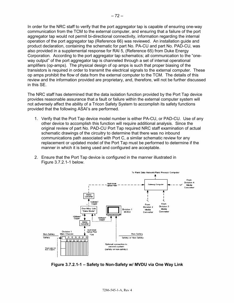
In order for the NRC staff to verify thcommunication from the TCM to theaggregator tap would not permit bi-doperation of the port aggregator tap product declaration, containing the salso provided in a supplemental respCorporation. According to the port away output” of the port aggregator taamplifiers (op-amps). The physical transistors is required in order to traop amps prohibit the flow of data froreview and the information providedin this SE. The NRC staff has determined that tprovides reasonable assurance thatnot adversely affect the ability of a Tprovided that the following ASAI’s ar
1. Verify that the Port Tap devicother device to accomplish thoriginal review of part No. PAschematic drawings of the cicommunications path associreplacement or updated modmanner in which it is being u
2. Ensure that the Port Tap devFigure 3.7.2.1-1 below.
Figure 3.7.2.1-1 – Safe
– 72 –
hat the port aggregator tap is capable of ensuringe external computer, and ensuring that a failure ofdirectional connectivity, information regarding the(Reference 66) was reviewed. An installation gu
schematic for part No. PA-CU and part No. PAD-ponse for RAI 5, (Reference 65) from Duke Energaggregator tap schematics; all communication to ap is channeled through a set of internal operatiodesign of op amps is such that proper biasing of nsmit the electrical signals to the external compu
om the external computer to the TCM. The details are proprietary, and, therefore, will not be furthe
the data isolation function provided by the Port Tt a fault or failure within the external computer sysTricon Safety System to accomplish its safety funre performed.
ce model number is either PA-CU, or PAD-CU. Uhis function will require additional analysis. SinceAD-CU Port Tap required NRC staff examination rcuitry to determine that there was no inbound ated with Port C, a similar schematic review for a
del of the Port Tap must be performed to determinsed and configured are acceptable.
vice is configured in the manner illustrated in
ety to Non-Safety w/ MVDU via One Way Link
g one-way f the port
e internal uide and CU, was gy the “one-
onal the
uter. These s of this
er discussed
ap device stem will ctions
Use of any e the of actual
any ne if the

– 73 –
In addition to the port tap device described above, the same layers of protection that apply to SR communications would also apply to communications with NSR equipment except that application layer protocols would not be used. Specifically, listed in order from the TCM back to the application processor, the mitigations are; TCM IP address discrimination, TCM data integrity check, IOCCOM single threaded bus master control scheme, IOCCOM data integrity check, IOCCOM com bus/ I/O bus separation, dual port RAM, fixed addressing in dual port RAM, read/write specific tag names for memory locations. The NRC staff determined that NSR equipment (e.g., plant computer) may be connected to the TCM through a port tap device as described above. This approval is subject to application specific review items noted above to verify the port tap device meets the precedent criteria (i.e., verify model number) and to verify port tap configuration in the system. An MVDU may be connected through the port tap as shown in Figure 3.7.2.1-1. However, approval of the MVDU will require review of plant specific procedures and review of the plant specific configuration. It is an ASAI to review all NSR communications connections through the TCM with regard to DI&C-ISG-04 as detailed in Section 3.7.3 of this SE. 3.7.2.2 NSR COMMUNICATIONS VIA THE REMOTE RXMS IOM’s Tricon V10 LTR asserted that the safety function is adequately protected when non-safety I/O is connected to the modules in a remote NSR RXM chassis. A remote NSR RXM chassis supports expansion of the safety I/O bus from the SR Primary RXMs via fiber optic cables. Such a connection represents two-way communication (RS-485 on the I/O bus) across the safety to non-safety barrier and adequate protection of the safety function must be demonstrated. Specifically, the upstream (closer to the application processor) SR portion of the I/O bus must be adequately protected from potential faults in the non-safety portion of the I/O bus. The NRC staff performed a detailed design review of the RXM connectivity within the Tricon V10 system, which included information in IOM letter dated August 3, 2010, “Supplementary Information –Selected Topics” (Reference 59, Items 1 and 4), responses to RAI questions 1 and 2 (Reference 8), and information obtained during the December 2010 audit at IOM (Reference 6). As stated in Section 3.1.2.3 of this SE, the RXMs are connected by fiber optic cables and not electrical cables, and therefore, provide ground loop isolation and immunity against electrostatic and EMI, and they can be used as Class 1E-to-Non-Class 1E isolators between a SR main chassis and a NSR expansion chassis. Therefore, the NRC staff finds that the fiber optic cable between the primary and remote RXMs do provide adequate electrical isolation as required by the above regulations. The NRC staff also identified several factors that support adequate data isolation protection of the safety function including I/O bus access, I/O bus control scheme and the protection of the safety function of the I/O bus by the interposing processor in the safety side RXM. As previously stated above, the dual port RAM and independent communications processor (IOCCOM) provide the primary protection for the safety processor. The IOCCOM verifies data integrity for all received messages. The I/O bus uses a single threaded master-slave configuration with IOCCOM as the bus master. The SR I/O bus access for NSR I/O data is controlled by an interposing processor in the RXM on the SR side such that no unrequested messages will be allowed onto the SR I/O bus. Further, the redundant Tricon V10 architecture will mitigate any single failures when the data is voted on the Tribus.

– 74 –
The NRC staff determined that the combination of these elements provided adequate protection to the safety side I/O bus and the overall safety function. All data received from a non-safety remote RXM must not be relied upon to perform the required safety function. Further NRC staff review and approval of this bidirectional NSR to SR data communication is provided below in Section 3.7.3. It is an ASAI to verify that adequate isolation is maintained in the application specific design and that no data received from the non-safety I/O is used by the control program to make a safety determination. 3.7.3 STAFF GUIDANCE IN DI&C-ISG-04 The NRC Task Working Group 4, "Highly Integrated Control Rooms-Communications Issues," developed interim NRC Staff Guidance on the review of communications issues applicable to digital safety systems. DI&C-ISG-04 (Reference 29) contains NRC staff positions on three areas of interest: (1) Interdivisional Communications, (2) Command Prioritization, and (3) Multidivisional Control and Display Stations. Evaluation of a safety system against this guidance is an application-specific activity that requires an assessment of a full system design. Since the LTR does not address a specific application or establish a definitive safety system design, the evaluation against this guidance is limited to consideration of the means provided within the platform to specifically address issues related to interactions among safety divisions and between SR equipment and equipment that is not SR. A full safety system design, which is based on the Tricon V10 system, will require further evaluation against this guidance as an ASAI. In IOM Document No. NTX-SER-09-10, Revision 2, "Compliance With NRC Interim Guidance ISG-2 & ISG-4" (Reference 29), IOM provided a position paper to explain how the Tricon V10 system (platform) design complies with the NRC staff guidance provided in DI&C-ISG-04, Revision 1 - Task Working Group No. 4 “Highly-integrated Control Rooms-Communications Issues.” 3.7.3.1 DI&C-ISG-04, STAFF POSITION 1 - INTERDIVISIONAL COMMUNICATIONS Staff Position 1 of DI&C-ISG-04 provides guidance on the review of communications, which includes transmission of data and information among components in different electrical safety divisions (or channels) and communications between a safety division and equipment that is not SR. This ISG does not apply to communications within a single division or channel. This NRC staff position states that bidirectional communications among safety divisions and between safety and non-safety equipment may be acceptable provided certain restrictions are enforced to ensure that there will be no adverse impact on safety systems. It goes on to say that systems which include communications among safety divisions and/or bidirectional communications between a safety division and non-safety equipment should adhere to the 20 points described below. The methods by which the Tricon V10 platform either meets these points or provides an acceptable alternative method of complying with NRC regulations are discussed below. 3.7.3.1.1 STAFF POSITION 1, POINT 1 Staff Position 1, Point 1, states that a safety channel should not be dependent upon any information or resource originating or residing outside its own safety division to accomplish its safety function. This is a fundamental consequence of the independence requirements of IEEE Std 603. It is recognized that division voting logic must receive inputs from multiple safety divisions.

– 75 –
As described in Section 3.1 of this SE, the Tricon V10 system safety channel is triple redundant from input terminal to output terminal, as shown in Figure 2-2. The triple modular redundant (TMR) architecture (i.e., three separate microprocessors) is intended to allow continued system operation in the presence of any single point of failure within the system. The TMR architecture is also intended to allow the Tricon V10 main processor (MP) to detect and correct individual faults on-line, without interruption of monitoring, control, and protection capabilities. In the presence of a fault, the Tricon V10 channel will alarm the condition, remove the affected portion of the faulted module from operation, and continue to function normally in a dual redundant mode. The system returns to the fully triple redundant mode of operation when the affected module is replaced. Each Tricon TMR-channel monitors dedicated sensors allowing bi-stable logic within the Tricon V10 to operate completely independent of other Tricon channels/divisions. As shown in Figure 2-2, the termination panels pass input signals from the field to an input module or pass signals generated by an output module directly to field wiring. The Tricon V10 LTR does not propose any interchannel/interdivisional communications or input from any external systems to perform the Tricon V10 safety function and therefore, each channel is not dependent upon any information or resource originating from outside its own safety division. As described in Section 3.1.2.1 of the SE, the Tricon V10 main chassis has a key switch that sets the system operating modes between RUN, PROGRAM, STOP, and REMOTE. When the Tricon V10 platform recognizes that the Tricon main processor is in an operational mode other than RUN, data can be provided to a safety channel from sources outside the respective channel (e.g., the TriStation 1131 PC). As described in Section 3.1.3.2 of this SE, plant procedures and administrative controls will restrict using the System Operating Mode keyswitch to change from the standard operational mode without placing the affected channel into bypass or trip. For configurations involving SR Primary RXM Chassis and non-safety Remote RXM Chassis, the independence requirements of IEEE Std 603 are satisfied through design characteristics as well as administrative controls. As stated in Sections 3.1.2.3 and 3.1.2.4 of this SE, non-safety RXMs can only be configured to communicate with its assigned division/channel. Therefore, NSR remote RXM chassis and modules are typically considered within a division/channel. Nonetheless, since a NSR remote RXM module is physically located outside a SR division/channel Class 1 boundary, its independence from its respective SR RXM is evaluated below. As stated in Section 3.7.2.2 of this SE, physical independence is maintained as follows:
The SR Primary RXM Chassis is physically separate from the non-safety Remote RXM Chassis. Multi-mode fiber optic cables connect the SR 4200 Primary RXM modules to the non-safety 4201 Remote RXMs. The combination of physically separate chassis as well as distance between chassis satisfies this criterion.
Electrical independence: The RXM Chassis utilizes dual-redundant power modules, with the capability to utilize both AC and DC site electrical power sources to the chassis. Each RXM Chassis is configured with its own pair of redundant power modules, with SR RXM Chassis powered from site vital electrical power sources, and the non-safety RXM Chassis powered from non-vital sources. The SR Primary RXM Chassis would have redundant, qualified power modules. Furthermore, the multi-mode fiber optic cable interconnection between the SR Primary RXM Chassis and non-safety Remote RXM Chassis provide ground loop isolation and immunity against electrostatic and EMI. This combination of redundant, separate chassis power

– 76 –
modules, site electrical sources, and RXM Chassis interconnection with fiber-optic cables meets the requirements for electrical independence. Data communications independence: The SR Primary RXM 4200 modules provide a gatekeeper function to ensure communication failures on the non-safety Remote RXM do not propagate to the SR portion of the I/O bus. The master-slave CPUs on SR Primary RXMs monitor data messages and enable data transfer to and from the non-safety RXMs only for valid command messages to the downstream non-safety I/O modules. Another layer of protection is provided to ensure data communication independence by the embedded IOCCOM processor on the SR 3008N MP. During a command-response sequence between the IOCCOM and a non-safety I/O module the IOCCOM checks for erroneous (including invalid and unexpected) and corrupted messages, and will time-out the sequence when a packet is delayed and/or missing. The combination of the IOCCOM and the gatekeeper function in the SR Primary RXMs meet the requirements for communications isolation. As a result of this review and the operational conditions noted above, the NRC staff determined that the Tricon V10 platform system complies with the guidance provided by Staff Position 1, Point 1. However, if a plant application of the Tricon V10 system invokes interchannel communications, then the specific interconnections defined for the plant-specific safety application must be determined and evaluated in a plant-specific review. 3.7.3.1.2 STAFF POSITION 1, POINT 2 Staff Position 1, Point 2, states that the safety function of each safety channel should be protected from adverse influence from outside the division of which that channel is a member. Information and signals originating outside the division must not be able to inhibit or delay the safety function. This protection must be implemented within the affected division (rather than in the sources outside the division), and must not itself be affected by any condition or information from outside the affected division. This protection must be sustained despite any operation, malfunction, design error, communication error, or software error or corruption existing or originating outside the division. Communications pathways to a safety channel (or division) have the highest potential to produce adverse influences to a safety channel from a safety division (or channel), which is outside the division. As shown in Figure 3.7.3.1.2-1 below, multiple layers of defense are designed into the Tricon V10 system, including the hardware, the software, and the IOM communication protocols themselves.

– 77 –
Figure 3.7.3.1.2-1 – Tricon V10 Communication Pathways The communication path into a Tricon V10 safety channel includes the multi-mode fiber optic cable, the TCM, the triplicated Communication Bus (COMBUS), and the TMR 3008N MPs, which themselves contain the IOCCOM processor, dual-port RAM (DPRAM), and the embedded application processor that executes the control program. The TCM provides functional isolation by handling all the communications with external devices, and it has been qualified under the IOM Appendix B program for nuclear applications. The fiber optic cable prevents propagation of electrical faults into the safety processors. In addition, the TCM has been designed for high-reliability and contributes to the overall reliability of the communication link through the use of CRCs, and testing has demonstrated that it will protect the safety core from network storms and other communication failures. Upon total loss of all TCMs, the safety core will continue to function and execute the application program. Furthermore, the Tricon V10 system has been tested by Wurldtech and it has been shown to be resilient against the communication faults. The COMBUS is a triplicated, internal communications bus utilizing a master-slave protocol with the TCM configured as the slave. The IOCCOM uses a CRC for integrity checks of COMBUS data. Each MP module contains an IOCCOM processor to handle the data exchange between the embedded application processor and either the I/O modules or the TCM. The IOCCOM processor is scan based, and does not use interrupts. IOCCOM maintains separation for I/O bus and COM message processing, applying checks on both the link-level formatting and CRCs. To ensure adequate execution time for SR I/O, the IOCCOM executes COM messages only while waiting for I/O responses. The application processor and IOCCOM exchange data through the DPRAM buffering system. The application safety processor has higher priority, but the design guarantees that the interface is shared – neither processor can starve the other processor accessing the DPRAM. The application processor assigns highest priority to executing the safety function, and messaging is rate-limited. In addition, the three safety 3008N MPs first vote on the message before acting on any message from the TCM. Another layer of protection to the safety function (processor) is provided by the communication protocols at the Application Layer of the OSI protocol stack. For all communication links between SR equipment, the P2P and SAP protocols ensure end-to-end integrity of safety-critical messages, and thus do not rely upon the TCM(s) or IOCCOM for message integrity. System architectures requiring data transfer between SR Tricon V10 platforms over a network would

– 78 –
use the P2P protocol over an isolated, point-to-point network. Architectures requiring safety-critical data exchanges with other SR devices (e.g., SR VDUs) would utilize the SAP protocol. Both protocols have been developed in accordance with the IOM Quality Assurance program and approved for use in nuclear SR applications (see Section 3.7.1 of this SE). Certain data integrity features are built into the protocols, such as message acknowledgement and negative acknowledgement (ACK/NAK). The non-safety TriStation 1131 computer will be used to reprogram the application program installed on the Tricon controller(s). During these activities the Tricon is taken out of service with site administrative procedures and by taking the Tricon keyswitch out of the RUN mode. The Tricon keyswitch is a physical interlock that controls the mode of the MPs. It prevents the TCM from accepting “write” messages when placed in the RUN position. The position of the keyswitch is continuously monitored by the TMR MPs, with the MPs voting on the detected position of the keyswitch. The Tricon is designed so that an application program output can be provided to activate an annunciator window in the control room when the keyswitch is not in the RUN position. Furthermore, as described in Section 3.1.3.2 of this SE, plant procedures, and administrative controls will restrict using the System Operating Mode keyswitch to change from the standard operational mode without placing the affected channel into bypass or trip. The TriStation 1131 cannot modify firmware in the Tricon controllers. A separate tool is used to perform firmware upgrades with the Tricon module (e.g., 3008N MP, TCM, I/O module) removed from the chassis. The Tricon controller would have to be taken out of service (keyswitch to STOP) and the module removed from the chassis. These activities would be under site-specific administrative controls and performed in accordance with site-specific procedures. For configurations involving SR Primary RXM Chassis and non-safety Remote RXM Chassis, Point 2 is satisfied through design characteristics of the Tricon V10 system. As stated in Sections 3.1.2.3 and 3.1.2.4 of this SE, non-safety RXMs can only be configured to communicate with its assigned division/channel. Therefore, NSR remote RXM chassis and modules are typically considered within a division/channel. Nonetheless, since a NSR remote RXM is physically located outside a SR division/channel Class 1 boundary, then the safety function of each safety channel should be protected from adverse influence from NSR RXMs associated with a division/channel. As described in Point 1 above, physical and electrical separation is inherent in the design of the RXM Chassis. As described in Section 3.1.2.4 of this SE, the purpose of the remote RXM Chassis is to extend the Tricon V10 system I/O bus to locations at distances farther than the standard 9000-series copper cables can handle. Therefore, a non-safety Remote RXM Chassis would be physically separated from the SR Main and Primary RXM Chassis. As described in the Tricon V10 LTR, the design of the Tricon V10 system RXM's does not allow data exchange between RXM Chassis in different safety divisions or channels. Hence, the Tricon V10 system is not dependent upon data from other safety divisions/channels. Deviations from this design would be a plant-specific configuration that would warrant further NRC review to verify compliance with this Point. The Primary RXM gatekeeper function (the master CPU) protects the SR segment of the I/O Bus from invalid or erroneous data from the NSR RXMs. The master-slave CPUs on SR Primary RXMs monitor data messages and enable data transfer to and from the non-safety RXMs only for valid command messages to the downstream non-safety I/O modules.

– 79 –
Another layer of protection is provided by the embedded IOCCOM processor on the SR 3008N MP module during a valid command-response sequence between the IOCCOM and a non-safety I/O module. The IOCCOM checks for erroneous (including invalid and unexpected) and corrupted messages, and will time-out the sequence when a packet is delayed and/or missing. The combination of the IOCCOM in the safety main processor (3008N) and the gatekeeper function in the SR Primary RXMs meet the requirements for protection of the safety processor despite any operation, malfunction, design error, communication error, or software error or corruption existing or originating outside the division. As a result of this review and the design and operational conditions noted above, the NRC staff determined that the Tricon V10 safety system provides protection of the safety function and complies with the guidance provided by Staff Position 1, Point 2. 3.7.3.1.3 STAFF POSITION 1, POINT 3 Staff Position 1, Point 3, states that a safety channel should not receive any communication from outside its own safety division unless that communication supports or enhances the performance of the safety function. Receipt of information that does not support or enhance the safety function would involve the performance of functions that are not directly related to the safety function. Safety systems should be as simple as possible. Functions not necessary for safety, even if they enhance reliability, should be executed outside the safety system. A safety system designed to perform functions not directly related to the safety function would be more complex than a system that performs the same safety function, but is not designed to perform other functions. The more complex system would increase the likelihood of failures and software errors. Such a complex design, therefore, should be avoided within the safety system. For example, comparison of readings from sensors in different divisions may provide useful information concerning the behavior of the sensors (for example, On-Line Monitoring). Such a function executed within a safety system, however, could also result in unacceptable influence of one division over another, or could involve functions not directly related to the safety functions, and should not be executed within the safety system. Receipt of information from outside the division, and the performance of functions not directly related to the safety function, if used, should be justified. It should be demonstrated that the added system/software complexity associated with the performance of functions not directly related to the safety function and with the receipt of information in support of those functions does not significantly increase the likelihood of software specification or coding errors, including errors that would affect more than one division. The applicant should justify the definition of “significantly” used in the demonstration. The design features of the Tricon V10 system as described in the LTR do not include any communications from outside a single channel (i.e., platform) that does not support the safety function. Each Tricon TMR-channel monitors dedicated sensors allowing bistable logic within the Tricon V10 to operate completely independent of other Tricon-channels/divisions. The termination panels pass input signals from the field to an input module or pass signals generated by an output module directly to field wiring. Consequently, the Tricon V10 platform is not overly complex and not subject to failures induced by complexity. The Tricon V10 system does include diagnostic and self-testing features which are built into the platform. However, these features are not dependent upon external inputs, and contribute to the Tricon V10 reliability and availability. As a result of this review and the Tricon V10 platform design features noted above, the NRC staff determined that the Tricon V10 safety system complies with the guidance provided by Staff

– 80 –
Position 1, Point 3. However, the Tricon V10 system does provide allowances for potential connections between SR Tricon controllers using the P2P protocol, between a SR Tricon controller(s) and a SVDU(s) using the Safety Application Protocol (SAP), or between SR Tricon controllers and non-safety devices (MVDUs, non-safety Tricon controllers, etc.) using a One Way Link (OWL) device as discussed in Sections 3.7.1 and 3.7.2.1 of this SE. Although the P2P and SAP communication protocols have been approved (see Section 3.7.1) for SR application, interdivisional communications between SR Tricon V10 controllers using the P2P, SAP, or communications between SR Tricon V10 controllers and non-safety systems using other protocols would require plant specific analysis to verify compliance with this staff position. 3.7.3.1.4 STAFF POSITION 1, POINT 4 Staff Position 1, Point 4, states that the communication process itself should be carried out by a communications processor separate from the processor that executes the safety function, so that communications errors and malfunctions will not interfere with the execution of the safety function. The communication and function processors should operate asynchronously, sharing information only by means of dual-ported memory or some other shared memory resource that is dedicated exclusively to this exchange of information. The function processor, the communications processor, and the shared memory, along with all supporting circuits and software, are all considered to be SR, and must be designed, qualified, fabricated, etc., in accordance with 10 CFR Part 50, Appendices A and B. Access to the shared memory should be controlled in such a manner that the function processor has priority access to the shared memory to complete the safety function in a deterministic manner. For example, if the communication processor is accessing the shared memory at a time when the function processor needs to access it, the function processor should gain access within a timeframe that does not impact the loop cycle time assumed in the plant safety analyses. If the shared memory cannot support unrestricted simultaneous access by both processors, then the access controls should be configured such that the function processor always has precedence. The safety function circuits and program logic should ensure the safety function will be performed within the timeframe established in the safety analysis, and will be completed successfully without data from the shared memory in the event that the function processor is unable to gain access to the shared memory. As described in the Triconex Topical Report (Reference 4), all Tricon communication with external devices is conducted and supervised by one or more separate TCMs, which are contained within the Tricon V10 Main Chassis (channel). The TCMs operate asynchronously, sharing information only at end of the application processor scan. When the external device requests data, the communication processor forwards the data from the application processor received at the previous end of scan. When an external device transmits data to the Tricon V10 safety application processor, the communication processor passes the data to the application processor at next end of scan exchange. A simplified view of the Tricon communications system is shown in the Figure 3.7.3.1.4-1 below.

– 81 –
Figure 3.7.3.1.4-1 – Tricon V10 Communications The TCM provides functional isolation by handling all the communications with external devices that may be connected to other divisions, and it has been qualified under the IOM Appendix B program for nuclear applications. A fiber optic cable is used between the TCM and external devices to prevent propagation of electrical faults into the safety processors. In addition, the TCM has been designed for high reliability and contributes to the overall reliability of the communication link through the use of Cyclic Redundancy Checks (CRCs). Testing has demonstrated that the TCM will protect the safety core from network storms and other communication failures (see Staff Position 1, Point 12). Upon total loss of all TCMs, the safety core will continue to function. The internal communication path for external devices to and from the Tricon V10 platform is via the TCM, to the triplicated Communication Bus (COMBUS), and the TMR 3008N MPs (all are safety related and contained within the SR Main Chassis). The MPs contain the IOCCOM processor, dual-port RAM (DPRAM), and the embedded application processors that execute the safety control program. Valid messages received by the TCM are triplicated for transmission on the COMBUS and then to the IOCCOM, which is running at its own scan rate without the use of interrupts. The IOCCOM processor retrieves data from the DPRAM to send to either the I/O modules or the TCM, or deposits I/O data or communications (COM) messages into the

– 82 –
DPRAM for use by the application processor. Separate queues are provided in the IOCCOM for I/O Bus and COM messages. To ensure adequate execution time for SR I/O, the IOCCOM executes COM messages from the TCM only while waiting for I/O responses. The IOCCOM checks the link-level format and the CRC of all messages from the TCM. If the IOCCOM determines that the message is valid and correct, the data is placed into DPRAM. Both the application processor and IOCCOM exchange data through the DPRAM. The application processor has higher priority, but the design is such that the interface is equally shared (i.e., neither processor can starve the other processor accessing the DPRAM). As with the IOCCOM, the DPRAM provides separate memory areas and queues for communication messages and I/O data. These “bins” are separated according to input, output, read-only, read-write, and data type (i.e., Boolean, Reals, Integers). The DPRAM includes extensive memory protection via parity checks, CRCs, checksum, and other mechanisms. As stated previously, the application processor assigns highest priority to executing the safety function, and messaging is rate-limited. The three 3008N MPs vote on the message before acting on any message from the TCM. Conversely, the TCM votes on the messages from the three 3008N MPs and sends a single copy to an external device if two out of three messages agree. The embedded application processor, IOCCOM, and TCM each runs its own scan loop (see Figure 2-6 in Section 3.1.3.1 of this SE). The embedded application processor and IOCCOM are synchronized to facilitate exchange of data through the DPRAM. The main scan loop (“ETSX”) of the embedded application processor consists of three tasks:
1) Scan Task, 2) Communication Task, and 3) Background Task.
The Scan Task sequence is essentially: Input data from DPRAM and vote → Process control program → Send outputs to DPRAM.
The Communication Task is run after the Scan Task during the “Scan Surplus” period. The embedded application processor and the IOCCOM scan loops are synchronized such that during the Communication Task the IOCCOM deposits I/O and communications messages into the DPRAM for use by the embedded application processor at the beginning of the next Scan Task. The IOCCOM scan loop (“IOC loop”) gives priority to I/O data exchanges. During the IOC loop when the IOCCOM is waiting for responses from the I/O modules, scan time is allotted for COM messaging via the COMBUS. As described in Sections 3.1.2.4 and 3.7.1.2 of this SE, another means of communications within a channel or division is via the remote RXMs. Communications data via the remote RXMs can be either SR or NSR data. NTX-SER-09-10, Section 2, “V10 Tricon Chassis Configurations,” and Section 3.2, “V10 Tricon Communications – Safety-to-Non-safety Communications,” propose safety-to-non-safety Tricon V10 architectures utilizing non-safety Remote Extender Chassis. Communications via the RXMs is accomplished as follows: The primary RXMs are qualified as Class 1E equipment. The remote RXMs are also qualified as Class 1E equipment, but may be used to transmit non-safety data to the primary RXMs and therefore must be evaluated as NSR equipment. Although the remote RXMs are qualified equipment, the connection of non-safety related I/O or use of non-1E power forces a NSR

– 83 –
designation for the entire remote chassis. The following paragraphs describe how the Tricon V10 works to provide adequate protection between a SR primary RXM and a remote RXM in a NSR chassis. The SR primary RXM contains two on-board microprocessors (CPUs) in a master-slave configuration. The master CPU monitors all messages coming from, and is directly polled by, the SR 3008N MP. The master CPU is responsible for the on-board diagnostics. It monitors the I/O bus for messages intended for the remote RXM in the NSR chassis, and provides the required responses. The slave CPU monitors all messages coming from the I/O modules (i.e., response messages from the remote RXMs). The slave CPU provides updated information to the master CPU regarding active I/O modules in its downstream path (e.g., in the non-safety RXM Chassis). Any errors the slave CPU detects are also passed to the master CPU. Together the master and slave CPUs enable/disable the communication multiplexer on the RXMs. In normal mode, whenever the master CPU detects that the chassis number embedded in a valid command from the SR 3008N MP is addressed to an I/O module in its downstream leg, it will enable the communication multiplexer. Otherwise, it will be disabled. Therefore, noise and erroneous messages received by the SR Primary RXM while the communication multiplexer is disabled will not be passed to the SR IOCCOM on the SR 3008N MP. Consequently, the normal operation of the SR 3008N MP is protected from faults and/or noise from the non-safety Remote RXM and non-safety I/O modules. The I/O Bus is composed of separate command and response buses, which are fiber optic cables that are used between the SR primary RXM and NSR Remote RXMs to prevent propagation of electrical faults into the safety processors. Commands from the SR IOCCOM on the SR 3008N MP are sent over a separate path than the responses from the I/O modules. This separation of commands and responses at the hardware level ensures that I/O modules (I/O Bus slaves) respond only to valid commands from the IOCCOM via the SR Primary RXM. The internal communication path for the primary RXM to and from the Tricon V10 safety function processor is via the triplicated I/O bus, then to the IOCCOM processor, and then to the DPRAM. As described for the TCM processors, communications between the safety function processor and the IOCOOM is via the DPRAM. The NRC staff has reviewed the design and functionality of the communications process and the hardware and software used to implement this process, and has determined that the Tricon V10 system complies with Staff Position 1, Point 4. 3.7.3.1.5 STAFF POSITION 1, POINT 5 Staff Position 1, Point 5, states that the cycle time for the safety function processor should be determined in consideration of the longest possible completion time for each access to the shared memory. This longest-possible completion time should include the response time of the memory itself and of the circuits associated with it, and should also include the longest possible delay in access to the memory by the function processor assuming worst-case conditions for the transfer of access from the communications processor to the function processor. Failure of the system to meet the limiting cycle time should be detected and alarmed. Staff Position 1, Point 4, and Section 3.1.3.1 of this SE describe the scan loop for the Tricon V10 controller. To summarize, the TMR 3008N MPs and TCM exchange messages asynchronously over the triplicated COMBUS. On board each 3008N MP, the embedded

– 84 –
application processor and IOCCOM processor exchange data via a DPRAM. The application processor has higher priority for accessing the DPRAM. Data is deposited into DPRAM at the end of the embedded application processor Scan Task, which the IOCCOM processor retrieves during its own scan loop (synchronized with the embedded application processor scan loop). During surplus scan time, the Communication Task is run and the embedded application processor retrieves messages from the DPRAM in preparation for the next Scan Task. Priority is given to the application program and I/O data exchanges, with communication message exchanges with the TCM via the COMBUS occurring between scans. As described in the IOM ISG-04 Position Paper (Reference 29) all data is exchanged at each End-of-Scan, therefore, communication message exchanges may require multiple scans to satisfy a host device (such as a Tricon, SVDU, or other device on the DCS) read or write communication function. Additional time (at least two scan loops) is required for a sending Tricon controller to get an acknowledgment from the receiving Tricon controller that the message has been received and processed. In fact, most messages from an external system require voting by the TMR 3008N MPs. Thus, typical message response times require three or more scans to complete – one scan to send and two scans for the response. The IOM protocols used for safety-critical communications, P2P and SAP, are discussed in Staff Position 1, Points 1 and 2 above. The SAP and P2P protocols are responsible for the end-to-end integrity of safety-critical communications, and thus will be implemented during plant-specific application software development. Because of the additional functions these protocols specify at the Application Layer to protect communications, P2P and SAP will place a burden on the application processor and therefore extend the Tricon controller cycle time. The Tricon V10 platform continuously monitors system functionality and performance, activating an alarm should scan time exceed the predicted performance. IOM Document No. 9600164-731 (Reference 43), “Maximum Response Time Calculation,” provides formulas to estimate the maximum response time for the various I/O module types. Application specific safety systems using the Tricon V10 platform will utilize the formulas and built-in features in the development of the SR application program. Also, thorough program operational testing will need to be conducted to determine the longest scan-time duration. The cycle times resulting from all these data processing activities will need to be calculated and compared to a plant's safety analysis to ensure safety-critical timing requirements are met. The Tricon V10 LTR did not provide a specific cycle time for the platform itself. In light of this evaluation, Staff Position 1, Point 5, cannot be assessed for the Tricon V10 platform and must be evaluated as an application specific review for a plant specific application. 3.7.3.1.6 STAFF POSITION 1, POINT 6 Staff Position 1, Point 6, states that the safety function processor should perform no communication handshaking and should not accept interrupts from outside its own safety division. For the Tricon V10 controller, the 3008N MP acts as the safety function processor in a Triple-Modular-Redundant configuration. Staff Position 1, Point 1, explains that Tricon V10 controllers are qualified TMR systems and are not dependent upon interdivisional communications or external systems to perform the safety function. This includes interrupts from external systems. The TMR 3008N MP application processors are isolated from data communications by the TCM. One or more TCM(s) act as the communication processor(s) to handle all communication protocol requirements (i.e., handshaking, start, stop bits). Also, the

– 85 –
TMR 3008N MP application processors are isolated from non-safety I/O data communications by the combination of the DPRAM, the IOCCOM, and the SR Primary RXM. There is no handshaking on the I/O bus. The NRC staff review of the communications protocols associated with the communications used by the Tricon V10 platform does use communications handshaking, but this handshaking is done by the TCM communications modules. However, the safety function processor contained within the TRM 3008N MP communicates externally using only the dual-ported memory, and this process does not use handshaking or interrupts as described in Sections 3.1.2.7 and 3.7.1 of this SE. The NRC staff has reviewed the use of communications handshaking, and has determined that since all handshaking during system operations is done by the communications processor, and not by the safety function processor, the Tricon V10 platform complies with Staff Position 1, Point 6. 3.7.3.1.7 STAFF POSITION 1, POINT 7 Staff Position 1, Point 7, states that only predefined data sets should be used by the receiving system. Unrecognized messages and data should be identified and dispositioned by the receiving system in accordance with the pre-specified design requirements. Data from unrecognized messages must not be used within the safety logic executed by the safety function processor. Message format and protocol should be pre-determined. Every message should have the same message field structure and sequence, including message identification, status information, and data bits, in the same locations in every message. Every datum should be included in every transmit cycle, regardless of whether it has changed since the previous transmission, to ensure deterministic system behavior. All communications with external devices including remote RXMs are limited to Tricon-compatible protocols, as described in Section 3.0, of the Tricon V10 Compliance with ISG-02 & 04 document. Each protocol is well-defined and ordered, i.e. number of start and stop bits, timing, data frame format, number of data fields and check sum or Cyclic Redundancy Check (CRC) field. Should an error occur, the communication processor rejects the message. The message length may vary, however, as an external device may request a different number of data points within each request. Extensive testing was performed by an independent third-party (Wurldtech) to validate the robustness of the Tricon V10 against communication failures. The Tricon V10 passed tests to verify the robustness of the TCM to various communication failures, such as proper handling of rogue and invalid protocol packets, and continued operation under network storm conditions without adverse impact on the TMR 3008N MP control algorithm. Ethernet, ARP, IP, ICMP, TCP, and UDP protocols were tested. The test configuration included monitoring of digital output signals to confirm that the Tricon application program running on the TMR 3008N MPs was unperturbed. Testing validated that the TCM will discard rogue, invalid, and excessive Ethernet packets (such as during data storms), thereby ensuring the operation of the TMR 3008N MPs was unperturbed during communication failures. Communication between the 3008N MP and the remote RXMs via an I/O module uses a serial, asynchronous, RS485 master-slave protocol at 375 Kbps. The format of I/O message commands is fixed. The master and slave CPU's on the RXM ensure the messages are properly formatted and are valid command messages (e.g., chassis number, leg number, and slot number, correct CRC) so that there is an expected corresponding response message for every command message. Also, the IOCCOM processor performs a validity check before

– 86 –
processing the response message (i.e., forwarding the I/O response data to the DPRAM on the 3008N MP for the embedded application processor to retrieve). Corrupted and improperly addressed messages will be ignored by the IOCCOM and I/O modules. Based on this information, the NRC staff has determined that the Tricon V10 platform complies with Staff Position 1, Point 7. 3.7.3.1.8 STAFF POSITION 1, POINT 8 Staff Position 1, Point 8, states that data exchanged between redundant safety divisions or between safety and non-safety divisions should be processed in a manner that does not adversely affect the safety function of the sending divisions, the receiving divisions, or any other independent divisions. As described above in Sections 3.7.1, 3.7.2, and Staff Position 1, Point 2, above for data exchanged between redundant safety divisions and for data exchanged between safety and non-safety portions of the Tricon V10 platform, all data exchanges are done using an interposing communications processor, and the safety function processor processes this data as part of the standard software loop. The Tricon V10 LTR indicates that there will be no data exchange between RXM Chassis in different safety divisions or trains. For this reason, the NRC staff has determined that the data exchange within the Tricon V10 platform complies with Staff Position 1, Point 8. 3.7.3.1.9 STAFF POSITION 1, POINT 9 Staff Position 1, Point 9, states that incoming message data should be stored in fixed predetermined locations in the shared memory and in the memory associated with the function processor. These memory locations should not be used for any other purpose. The memory locations should be allocated such that input data and output data are segregated from each other in separate memory devices or in separate pre-specified physical areas within a memory device. As described in Staff Position 1, Point 4, the internal communication path for external devices to and from the Tricon V10 platform is via the TCM and/or RXMs, to the triplicated Communication Bus (COMBUS) and/or I/O bus, and to the TMR 3008N MPs (all are safety related and contained within the SR Main Chassis). The SR 3008N MP contains an application processor, DPRAM, and IOCCOM processor. The application processor executes the SR application program. The IOCCOM handles interactions with the TCM via the COMBUS and the I/O subsystem via the I/O Bus, utilizing dedicated memory locations for communications and I/O data. All communications between the safety function processor and the IOCCOM and/or the RXMs are via the DPRAM. Data received by the Tricon V10 is stored in fixed "aliased" memory locations (an alias is a unique identifying integer value, which is automatically assigned by the TriStation 1131 application programming tool to input, output, and system variables), which are utilized by the application processor when computing application logic. Input data is segregated from output data within memory. The DPRAM provides separate memory areas and queues for communication messages and I/O data. The communications processor uses physically different areas (or bins) of the DPRAM for receiving and sending data. The memory locations used for each message is determined at the time of program compilation. The DPRAM includes extensive memory protection via parity checks, CRCs, checksum, and other mechanisms. For these reasons, the NRC staff has determined that the dual-ported memory usage, in terms of

– 87 –
separate areas for input and output data and for fixed memory usage within the Tricon V10 platform complies with Staff Position 1, Point 9. 3.7.3.1.10 STAFF POSITION 1, POINT 10 Staff Position 1, Point 10, states that safety division software should be protected from alteration while the safety division is in operation. On-line changes to safety system software should be prevented by hardwired interlocks or by physical disconnection of maintenance and monitoring equipment. A workstation (e.g., engineer or programmer station) may alter addressable constants, setpoints, parameters, and other settings associated with a safety function only by way of the dual-processor/shared-memory scheme described in this guidance, or when the associated channel is inoperable. Such a workstation should be physically restricted from making changes in more than one division at a time. The restriction should be by means of physical cable disconnect, or by means of keylock switch that either physically opens the data transmission circuit or interrupts the connection by means of hardwired logic. “Hardwired logic” as used here refers to circuitry that physically interrupts the flow of information, such as an electronic AND gate circuit (that does not use software or firmware) with one input controlled by the hardware switch and the other connected to the information source: the information appears at the output of the gate only when the switch is in a position that applies a “TRUE” or “1” at the input to which it is connected. Provisions that rely on software to effect the disconnection are not acceptable. It is noted that software may be used in the safety system or in the workstation to accommodate the effects of the open circuit or for status logging or other purposes. A non-safety computer is used to upgrade module firmware and/or reprogram the application program installed on the Tricon V10 controller(s). During these activities the Tricon is taken out of service with site administrative procedures and by taking the Tricon keyswitch out of the RUN mode. The Tricon keyswitch is a physical interlock that controls the mode of the 3008N MPs. It prevents the 3008N MPs from accepting “write” messages when placed in the RUN position. This keyswitch is described in Section 3.3.1.3 of IOM Document No. NTX-SER-10-14, “Tricon V10 Conformance to Regulatory Guide 1.152” (Reference 35). It describes the physical protection of the embedded firmware and the process that must be followed to update the software. The keyswitch is implemented by a three-gang, four-position switch. Each of the gangs is connected to one of the 3008N MPs. The values are read by each of the 3008N MPs as a two bit software value. The position of the keyswitch is continuously monitored by the TMR MPs, with the MPs voting on the detected position of the keyswitch. The Tricon is designed so that an application program output can be provided to activate an annunciator window in the control room when the Tricon keyswitch is not in the RUN position. The application program has access to the voted keyswitch position through specialized function blocks. These specialized function blocks allow monitoring (i.e., read-only capability) of a system variable for the voted keyswitch position. The application can be programmed to perform any required action on a change of the keyswitch position. However, this would be an application specific feature that is beyond the scope of this review. During firmware updates of the Tricon controllers the Tricon module (e.g., 3008N MP, TCM, I/O module) is removed from the chassis. The Tricon controller would have to be taken out of service (keyswitch to STOP) and the module removed from the chassis. These activities would be under site-specific administrative controls and performed in accordance with site-specific procedures. The keyswitch design mitigates against any single hardware fault. If one of the gangs on the switch goes bad or an input to a 3008N MP fails (e.g., a single bit flip), the error would affect only the 3008N MP that is attached to the failed gang. The other two 3008N MPs would

– 88 –
continue to receive good inputs values and out vote the 3008N MP with the bad input. This protects against any single fault in the physical keyswitch or on the 3008N MP. Section 3.1.2 of this SE discusses other administrative control options that may be invoked to ensure on-line changes to safety system software are prevented. The I/O subsystem, which includes the RXM Chassis, cannot be modified during run time. There is no interface with the operator or TriSation 1131 user that would allow modification of the RXM firmware during run time. Modification or update of RXM firmware requires 1) removal of the RXM from the RXM Chassis, and 2) special tools to interface directly with the single RXM; IOM neither provides nor sells these tools to its customers. However, the Tricon V10 keyswitch does not provide a physical disconnect or interruption of the connection by means of hardwired logic as required by ISG 4, Staff Position 1, Point 10, but instead sets 2 bits within the software to change the operating mode of the Tricon. Therefore, the Tricon V10 relies on software to effect the disconnection of the TriStation capability to modify the safety system software, a condition specifically stated as not acceptable in this ISG staff position. Based on the information provided in the LTR, the NRC staff determined that the Tricon V10 platform does not meet the NRC staff guidance provided in Staff Position 1, Point 10. In order for the NRC staff to accept this keyswitch function as compliant with this Staff Position, the NRC staff will have to evaluate an application specific system communications control configuration--including the operation of the keyswitch, the software affected by the keyswitch, and any testing performed on failures of the hardware and software associated with the keyswitch. This is an ASAI associated with the implementation of this keyswitch. 3.7.3.1.11 STAFF POSITION 1, POINT 11 Staff Position 1, Point 11, states that provisions for interdivisional communication should explicitly preclude the ability to send software instructions to a safety function processor unless all safety functions associated with that processor are either bypassed or otherwise not in service. The progress of a safety function processor through its instruction sequence should not be affected by any message from outside its division. For example, a received message should not be able to direct the processor to execute a subroutine or branch to a new instruction sequence. As discussed in Sections 2.2, 3.2.1, and 3.1 of this SE, the Tricon V10 platform is a qualified TMR system and is not dependent upon interdivisional communications or external systems to perform the safety function. P2P and SAP communication protocols are utilized for safety-critical communications between the SR Tricon V10 controller and other Tricon controllers or SR systems. However, the Tricon P2P and SAP messages support data exchange only. There are no “flow-of-control” message functions in the P2P or SAP protocols. Moreover, the RXM Chassis provides no means to send software instructions to the SR 3008N MP. The RXM Chassis only provides the capability to handle I/O at remote locations. The I/O Bus protocol is a single-threaded, command-response serial protocol for transferring I/O data as well as I/O module status. By design, software commands allowing remote control of the SR 3008N MP from the RXM Chassis is not possible. Firmware changes are performed while the RXMs are removed from the chassis. Any modifications to the I/O subsystem configuration, such as adding or deleting an I/O module(s) or changing to a different model I/O module, would be a significant hardware change to the Tricon system and could not be performed on line.

– 89 –
Also, the design of the RXMs does not enable data exchanges between RXM Chassis in different safety divisions or channels. As discussed in Sections 3.1.2.1 and 3.1.3.2 of this SE, with the Tricon Operational Mode Change keyswitch in RUN, each Tricon V10 is independent of other channels/divisions. Any architecture in which one division relies upon data from another division would be site-specific and thus would warrant plant-specific reviews by the NRC staff. The Tricon V10 system Operational Mode Change keyswitch does change operational modes of the 3008N MPs and enables the TriStation 1131 PC to change parameters, software algorithms, etc, related to the application program of the safety channel without the channel or division being in bypass or in trip. As stated in Section 3.1.3.2 of the SE, the TriStation 1131 PC should not normally be connected while the Tricon V10 is operational and performing safety critical functions. However, it is physically possible for the TriStation PC to be connected at all times, and this should be strictly controlled via administrative controls (e.g., place the respective channel out of service while changing the software, parameters, etc). Furthermore, in order to leave the non-safety TriStation 1131 PC attached to the SR Tricon V10 system while the key switch is in the RUN position, a detailed FMEA of the TriStation 1131 PC system will be required to ascertain the potential effects that this non-safety PC may have on the execution of the safety application program/operability of the channel or division. This would be evaluated on an application specific basis. Based on the design of the Tricon V10 platform as evaluated above and strict administrative controls (as indicated above) over the use of these keys switches the NRC staff has determined that the Tricon V10 platform does comply with Staff Position 1, Point 11. 3.7.3.1.12 STAFF POSITION 1, POINT 12 Staff Position 1, Point 12, states that communication faults should not adversely affect the performance of required safety functions in any way. Faults, including communication faults, originating in non-safety equipment, do not constitute “single failures” as described in the single failure criterion of 10 CFR Part 50, Appendix A. This section provides 12 examples of credible communication faults, but cautions that the possible communication faults are not limited to the list of 12. As discussed in Points 2 and 4 above, electrical and functional isolation of the 3008N MPs are provided by the TCM, which has a reliable design, and includes several engineered layers of protection against communication failures. As stated previously, the SR TCM handles all external communications, and thus serves as an isolation or buffer for the TMR 3008N MPs from communications data. Also, as described in Section 3.1.2.8 of this SE, the Tricon communication P2P and SAP protocols provide end-to-end integrity checks of all communications data. The design and operation of the Tricon V10 is intended to prevent communication faults from altering the application program or its performance. In conjunction with these platform design features, testing was performed by an independent third-party (Wurldtech) to validate the robustness of the Tricon V10 platform against communication failures. Wurldtech performed testing of a number of scenarios testing the communications link in the presence of a communications failure. This testing is discussed in this SE Section 3.8.1.2, and is documented in Appendix A of IOM Document No. NTX-SER-10-14 (Reference 35). This report and the data it contains is proprietary, and will not be discussed in this SE. However, in summary this testing verified the effectiveness of the TCM to cope with various communication failures, such as proper handling of rogue and invalid

– 90 –
protocol packets, and continued operation under network storm conditions without adverse impact on the TMR 3008N MP control algorithm. Ethernet, ARP, IP, ICMP, TCP, and UDP protocols were tested. The test configuration included monitoring of digital output signals to confirm that the Tricon application program running on the TMR 3008N MPs was unperturbed. This testing validated that the TCM will discard rogue, invalid, and excessive Ethernet packets (such as during data storms), thereby ensuring the operation of the TMR 3008N MPs was unperturbed during communication failures. The results of the Wurldtech testing validated the added reliability that the TCM provides to the communication link. Furthermore, as discussed in the IOM Document No. NTX-SER-09-10, Revision 2, “Compliance with NRC Interim Guidance ISG-2 & ISG-4,” the P2P and SAP communications protocol design further enhances mitigation of communication faults, including those enumerated in the Staff Position, Point 12. Also, communications data faults emanating from non-safety remote RXMs are mitigated by the data validation features of the master and slave CPUs within the SR primary RXMs and the IOCCOM processor in the MPs. Based on the robust design of the Tricon V10 platform to mitigate or eliminate communications data errors, and the NRC staff's review of the Wurldtech report (as discussed in Section 3.8.3.1 of this SE) allowed the NRC staff to determine that communications faults, including the 12 examples contained in Staff Position 1, Point 12, will not adversely affect the performance of the required safety functions, and that the Tricon V10 platform complies with Staff Position 1, Point 12. 3.7.3.1.13 STAFF POSITION 1, POINT 13 Staff Position 1, Point 13, states that vital communications, such as the sharing of channel trip decisions for the purpose of voting, should include provisions for ensuring that received messages are correct and are properly understood. Such communications should employ error-detecting or error-correcting coding along with means for dealing with corrupt, invalid, untimely or otherwise questionable data. The effectiveness of error detection/correction should be demonstrated in the design and proof testing of the associated codes, but once demonstrated is not subject to periodic testing. Error-correcting methods, if used, should be shown to always reconstruct the original message exactly or to designate the message as unrecoverable. None of this activity should affect the operation of the safety-function processor. As discussed in Section 3.1.1 of this SE, each Tricon TMR-channel monitors dedicated sensors allowing bi-stable logic within the Tricon V10 to operate completely independent of other Tricon-channels/divisions. As shown in Figure 2-2, the termination panels pass input signals from the field to an input module or pass signals generated by an output module directly to field wiring. The Tricon V10 LTR does not propose any interchannel/interdivisional communications or input from any external systems to perform the Tricon V10 safety function and therefore, each channel is not dependent upon any information or resource originating from outside its own safety division. Staff Position 1 Point 1 explains how each Tricon V10 is self-contained. Architectures involving vital communications between channels or divisions, such as for voting trip decisions, are supported using the P2P and SAP SR communication protocols, as explained in Section 3.7.1 of this SE. However, such architectures would be site-specific, and would require staff review and approval on an application specific basis. Also, there are no data exchanges between RXM Chassis in different safety divisions or trains. Furthermore, non-safety Remote RXM Chassis will not be utilized for vital communications.

– 91 –
The NRC staff reviewed the Tricon V10 system as described above and in the LTR and determined that this configuration of the Tricon V10 platform complies with Staff Position 1, Point 13. 3.7.3.1.14 STAFF POSITION 1, POINT 14 Staff Position 1, Point 14, states that vital communications should be point-to-point by means of a dedicated medium (copper or optical cable). In this context, “point-to-point” means that the message is passed directly from the sending node to the receiving node without the involvement of equipment outside the division of the sending or receiving node. Implementation of other communication strategies should provide the same reliability and should be justified. As discussed in Section 3.1.1 of this SE, each Tricon TMR-channel monitors dedicated sensors allowing bi-stable logic within the Tricon V10 to operate completely independent of other Tricon-channels/divisions. The Tricon V10 system is triple redundant from input terminal to output terminal. Figure 2-2 shows the arrangement of the input, main processor, and output modules. The termination panels pass vital input signals directly from the field to an input module or pass signals generated by an output module directly to field wiring. Each input and output module includes three separate and independent input or output circuits or legs. These input/output legs communicate independently in a point-to point manner with the three main processor modules. The Tricon V10 LTR does not propose any interchannel/interdivisional communications or input from any external systems to perform the Tricon V10 safety function and therefore, each channel is not dependent upon any information or resource originating from outside its own safety division. As described in Section 3.8.1.2 of this SE, the LTR and IOM Document No. NTX-SER-10-14 (Reference 35) credit the triplicated communications busses (I/O and COMBUS) as being physically separate. The communications processors (IOCCOM) are autonomous and separate from the safety function (application) processors. Communications between the safety function processor and its IOCCOM is point-to-point using a half-duplex master-slave protocol. IOCCOM is scan based with no interrupts and gives priority to safety I/O communications by design. CRC checks are performed on all data received by IOCCOM through both I/O and COMBUS paths. The Tricon V10 system utilizes point-to-point routed network communications protocol and media, copper and fiber optic cables to communicate data externally. All external communications uses a two-point network, where there is no equipment other than the sending and receiving nodes on the network. All communication protocols for vital communications (i.e., communications that are needed to support a safety function) support redundant communication links. Additionally, there is no data exchange between Remote RXM Chassis in different safety divisions or trains, and non-safety Remote RXM Chassis are not be utilized for vital communications. The NRC staff has reviewed this information and has determined that the Tricon V10 platform as described above and in the V10 LTR complies with Staff Position 1, Point 14, for point-to-point communications. 3.7.3.1.15 STAFF POSITION 1, POINT 15 Staff Position 1, Point 15, states that communications for safety functions should communicate a fixed set of data (called the "state") at regular intervals, whether data in the set has changed or not. As described above in Sections 3.1.3.1 and 3.7.3.1.7 of this SE, communications for safety functions have predefined data sets and therefore, communicate a fixed set of data. This data

– 92 –
is sent every scan cycle and at regular intervals, whether data in the set has changed or not. NTX-SER-09-10 Section 5.0 discusses the Tricon scan cycle in detail. In summary, at least once every Scan Task the I/O input data is retrieved and I/O data sets are sent to the I/O modules. The I/O Bus message formats are fixed (though data length can vary depending upon the valid command-response sequence). Communications to external SR applications are limited to Tricon V10-compatible protocols. Each protocol is well-defined and ordered (e.g., number of start and stop bits, timing, data frame format, number of data fields and check sum or CRC field). If an error were to occur, the communication processor would reject the message. Again, message length may vary because an external device may request a different number of data points within each request. Based on this information, the NRC staff has determined that the communications data set and transmission intervals as used in the Tricon V10 platform complies with Staff Position 1, Point 15. 3.7.3.1.16 STAFF POSITION 1, POINT 16 Staff Position 1, Point 16, states that network connectivity, liveness, and real-time properties essential to the safety application should be verified in the protocol. Liveness, in particular, is taken to mean that no connection to any network outside the division can cause an RPS/ESFAS communication protocol to stall, either deadlock or livelock. [Note: This is also required by the independence criteria of: (1) 10 CFR Part 50, Appendix A, GDC 24, which states, “interconnection of the protection and control systems shall be limited so as to assure that safety is not significantly impaired,” and (2) IEEE Std 603-1991, “IEEE Standard Criteria for Safety Systems for Nuclear Power Generating Stations” (Source: NUREG/CR-6082, Section 3.4.3)]. As described in Staff Position 1, Point 1, the Tricon V10 LTR does not propose any interchannel/interdivisional communications or input from any external systems to perform the Tricon V10 safety function and therefore, each channel is not dependent upon any information or resource originating from outside its own safety division. Also, the independence of the Tricon V10 controllers from external devices discussed in Staff Position 1, Points 1 and 2 describe the independence of Tricon V10 controllers from external devices, which includes engineered layers of protection against communication failures. The TCM has been qualified under IOM Appendix B program, and it provides functional and electrical isolation for the TMR 3008N MP safety processors. As discussed in Section 3.1.2.8 of this SE, the P2P and SAP communications protocols are used for communications of safety critical data between other Tricon platforms and SVDU respectively. End-to-end integrity checking of SR communications links is provided through the use of validation bits and timing within the message, so that the receiving Tricon or SVDU, as appropriate, is “aware” that the messages are current and not static. If the messages are detected to be static, lost, or significantly delayed, the receiving Tricon/SVDU activates an alarm. In the case of a receiving SR Tricon, it will assume the “fail-safe” status of the transmitting Tricon. The I/O Bus is an "internal system" bus based on RS485. The I/O Bus protocol is single-threaded master-slave serial protocol. By design, one command message is sent from the SR IOCCOM at a time and no other command messages are sent until a valid response from the non-safety I/O module is received, or the message thread times out. Also, every Scan Task, the SR IOCCOM polls a given I/O module at most once every 10 msec. Based upon this

– 93 –
information, the NRC staff has determined that the Tricon V10 platform meets the guidance provided by Staff Position 1, Point 16, for network connectivity. 3.7.3.1.17 STAFF POSITION 1, POINT 17 Staff Position 1, Point 17, states that pursuant to 10 CFR 50.49, the medium used in a vital communications channel should be qualified for the anticipated normal and post-accident environments. For example, some optical fibers and components may be subject to gradual degradation as a result of prolonged exposure to radiation or to heat. In addition, new digital systems may need susceptibility testing for EMI/RFI and power surges, if the environments are significant to the equipment being qualified. The environmental qualification for the Tricon V10 platform is described in the Section 3.3 of this SE. The generic qualification of the Tricon V10 encompasses both the hardware and the software used in the system. The hardware includes termination assemblies, signal conditioners, chassis, power supplies, main processor modules, communication modules, input/output modules, termination assemblies, module interconnecting cables, and Class 1E to Non-Class 1E module Isolation devices. The Tricon V10 platform was qualified in accordance with the EPRI TR-107330 requirements. The medium used for vital communications within the platform was a part of each of the systems qualified and is therefore qualified as described. The Tricon V10 platform was tested for EMI and RFI to demonstrate its qualification as a SR device with respect to EMI/RFI emissions and susceptibility. The platform was also subjected to Electrical Fast Transient (EFT) and Surge Withstand testing to demonstrate its qualification as a SR device with respect to susceptibility to repetitive EFTs on the power and signal input/output leads, and AC power and signal line electrical surge withstand capability. The NRC staff approved this qualification testing within the qualification limits noted in Section 3.3 of this SE. However, as noted in Section 3.3.1 of this SE, the qualification of the Tricon V10 does not include the fiber optic cables used to connect external devices to the safety application processor via the TCM or the RXMs. Therefore, an application specific evaluation will be required for plant specific applications of the Tricon V10 system utilizing fiber optic cables to connect external devices to the Tricon V10 platform. The NRC staff has determined that the Tricon V10 platform meets the guidance provided by Staff Position 1, Point 17. However, as noted above, fiber optic cables used to implement the Tricon V10 system in safety applications will require application specific review to verify these cables are qualified for the environment in which they will be used, in accordance with 10 CFR 50.49 as applicable. 3.7.3.1.18 STAFF POSITION 1, POINT 18 Staff Position 1, Point 18, states that provisions for communications should be analyzed for hazards and performance deficits posed by unneeded functionality and complication. IOM performed a FMEA on the Tricon V10 system in accordance with the applicable requirements of EPRI TR-107330 Section 6.4.1. In general, the techniques of ANSI/IEEE Std 352-1987 were used in the analysis. The results of the FMEA are documented in IOM Document No. 9600164-531, “Failure Modes and Effects Analysis for the Tricon Version 10.2 Programmable Logic Controller” (Reference 28). The FMEA addresses failures of major components and at the module level. The approach was appropriate because sub-components

– 94 –
in the Tricon modules are triple-redundant, and no single failure of an individual subcomponent can impact the ability of the Tricon to perform its SR functions. To summarize, the Tricon Communication Module (TCM) handles all communications protocol, start/stop bits, handshaking, etc. tasks. The 3008M MPs are neither burdened nor interrupted by communications faults. Communication errors and malfunctions do not interfere with the execution of the safety function. Exchange of data between the communication processors and MPs occur once each MP scan cycle. Because all the communication with external devices, systems, and hosts is performed by and localized in the TCM, the 3008N MPs are alleviated of unneeded communications functionality and attendant complications due to complexity. This mitigates any deficiencies in the TCM with regard to performance deficits posed by unneeded functionality. The I/O Bus is an internal system bus based on RS485. The I/O Bus protocol is single-threaded master-slave serial protocol. By design one command message is sent from the SR IOCCOM, and no other is sent until a valid response from the non-safety I/O module is received, or the data thread times out. Also, every Scan Task, the SR IOCCOM polls a given I/O module at most once every 10 msec. The RXMs are relatively simple modules, because they simply act as I/O Bus repeaters with gatekeeper functionality implemented within the RXM processors. This analysis included potential failures of communications used within the Tricon V10 system. The NRC staff reviewed and concurred with this FMEA in Section 3.5 of this SE. In addition, the Tricon self-diagnostic features have been specifically designed to detect and alarm failures of sub-components within each module. Extensive testing has been performed on each module to validate that the diagnostics detect all possible single failures within each module. IOM also provide a FMEA for the non-safety Remote RXM chassis in Table 3 of NTX-SER-09-10, Revision 2, which is considered an extension of the Tricon V10 FMEA discussed in Section 3.5 of this SE. This assessment identified the mechanisms that could cause the failure modes, and evaluated the consequences of the failures on the operation of the SR portion of the configuration (i.e., SR 3008N MPs, Primary RXM chassis, and I/O modules). Because of the architecture of the Tricon, failure mechanisms that affect a single leg of the triple redundant system generally have no effect on system operation. Therefore, the FMEA considered (1) failure mechanisms that are recognized as being highly unlikely but that could affect multiple components, and (2) the coincident occurrence of otherwise single failures (i.e., multiple failures). Multiple-failure scenarios include failures of all three non-safety Remote RXMs due to software common mode failure, loss of all power, fire, floods, or missiles. These types of multiple-failure scenarios are recognized as being very unlikely, but were included to describe system behavior in the presence of severe failures. Congestion is not a concern, because the I/O Bus is a closed system utilizing a single-threaded master-slave serial protocol based on RS485. By design one command message is sent from the SR IOCCOM and no other messages are sent until a valid response from the non-safety I/O module is received, or the message thread times out. Also, the SR IOCCOM polls a given I/O module at most once every 10 msec. Therefore, data rates are strictly defined and controlled. The NRC staff determined that these failure modes and effects analyses for the Tricon V10 system meet the guidance provided in Staff Position 1, Point 18.

– 95 –
3.7.3.1.19 STAFF POSITION 1, POINT 19 Staff Position 1, Point 19, states that the communications data rates be such that they will not exceed the capacity of a communications link or the ability of nodes to handle traffic, and that all links and nodes have sufficient capacity to support all functions. To do this, the applicant should identify the true data rate, including overhead, to ensure that communication bandwidth is sufficient to ensure proper performance of all safety functions and that communications throughput thresholds and safety system sensitivity to communications throughput issues should be confirmed by testing. Communications within the Tricon V10 platform is cyclic in nature as described in Sections 3.1.3.1 and 3.7.3.1.4 of this SE. The Communication task runs every 10 msec or when a communication port interrupt occurs. Factors which affect the platform communications performance include: COMBUS speed; the amount of aliased data and scan time; network speed and loading; and the particular communication protocol being used. The COMBUS speed determines the speed at which data is communicated between the 3008N MPs and TCMs. If the amount of aliased data updated by the 3008N MPs is too large for a single scan, then it may take several scans to update the aliased data stored in the TCMs. Network communication speeds with the TCM is 100 megabits-per-second, which means that it is highly unlikely that data transfer between the TCM and remote safety applications will be affected by the physical network. In the event that the 3008N MPs are excessively burdened with data requests, the Tricon continuously monitors system functions and performance, activating an alarm should scan time exceed the predicted performance. Also, as discussed in Sections 3.1.2.9 and 3.7.3.1.7 of this SE, extensive testing was performed by an independent third-party (Wurldtech) to validate the robustness of the Tricon V10 platform against communication failures. The Tricon V10 platform was tested to verify the robustness of the TCM to various communication failures, such as proper handling of rogue and invalid protocol packets, and continued operation under network storm conditions without adverse impact on the TMR 3008N MP control algorithm. Ethernet, ARP, IP, ICMP, TCP, and UDP protocols were tested. The test configuration included monitoring of digital output signals to confirm that the Tricon application program running on the TMR 3008N MPs was unperturbed. Testing validated that the TCM will discard rogue, invalid, and excessive Ethernet packets (such as during data storms), thereby ensuring the operation of the TMR 3008N MPs was unperturbed during communication failures. However, in order to assess the platform's performance against this Staff Position, the entire safety system application should be available and evaluated. For example, it is necessary to understand the exact communication protocols used to implement communications between the 3008N MPs and external safety and non-SR applications. Based on the safety system design, data transfer time calculations can be used to determine whether safety-critical timing requirements in the plant-specific safety analysis are met by the Tricon V10 communications protocols. Also, thorough program operational testing will need to be conducted to determine the longest scan-time duration, identify the true system data rate, including overhead, and ensure that communication bandwidth is sufficient to ensure proper performance of all safety functions and that communications throughput thresholds and safety system sensitivity to communications throughput issues are confirmed by testing. Determination that the safety system communications data rates be such that they will not exceed the capacity of a communications link or the ability of nodes to handle traffic and that all links and nodes have sufficient capacity to support all functions is an application-specific activity that requires an assessment of a full system design. Since the LTR does not address a specific

– 96 –
application and the scope of the platform does not include this system level information, no evaluation of the Tricon V10 platform against Staff Position 1, Point 19 could be performed. Therefore, implementation of the Tricon V10 platform in safety system applications will require application specific review to verify it meets the guidance of this Staff Position. 3.7.3.1.20 STAFF POSITION 1, POINT 20 Staff Position 1, Point 20, states that the safety system response time calculations should assume a data error rate that is greater than or equal to the design basis error rate and is supported by the error rate observed in design and qualification testing. “Response time” is generally defined as the total time elapsed from initiation of a change in process control signal at one end of an instrumentation loop (the detector or sensor) until the end-of-loop actuated device reaches its final desired position. Safety system response time is dependent upon the specific plant process and safety system architecture. The plant safety analysis determines the response time required, including error rate, to prevent exceeding a safety limit. The Tricon V10 processor is only one contributor to the overall response time computation, and this variable is referred to as the “throughput” of the Tricon processor. Throughput is generally referred to as the time required for processing a change in any signal or variable from the input screws to output screws of the Tricon V10 cabinet. Throughput is dependent upon a number of factors, such as the number of variables scanned, size and complexity of the application program, when a change in a signal or variable is detected, number of communications protocol variables being transmitted/received, etc. Because of the number of factors involved, throughput cannot be exactly predicted for any given configuration without knowing the exact safety system design. However, IOM did perform a calculation of throughput, documented in IOM Document No. 9600164-731, Revision 0, “Maximum Response Time Calculations” (Reference 43), which was used for the Tricon V10 qualification testing as required by Section 4.2.1-A of EPRI TR-107330, “General Functional Requirements,” Part A, “Response Time.” The TR specifies that, “the overall response time from an input to the PLC exceeding its trip condition to the resulting outputs being set shall be 100 msec or less.” IOM analysis determined that the theoretical maximum response time for different combinations of Digital Inputs, Digital Outputs, AIs and AOs. The analysis indicates that none of these combinations of input and output modules comply with the 100 msec requirement (i.e., they all exceed this value). However, this analysis may be useful in determining the overall throughput for a safety system. Actual scan time, throughput, and data error rates will be measured and recorded during the plant-specific Factory Acceptance Tests (FATs). Determination that the safety system response time calculations should assume a data error rate that is greater than or equal to the design basis error rate and is supported by the error rate observed in design and qualification testing is an application-specific activity that requires an assessment of a full system design. Since the LTR does not address a specific application and the scope of the platform does not include this system level information, no evaluation of the Tricon V10 platform against Staff Position 1, Point 20 could be performed. Therefore, implementation of the Tricon V10 platform in safety system applications will require application specific review to verify that it meets the guidance of this Staff Position.

– 97 –
3.7.3.2 DI&C-ISG-04, SECTION 2 - COMMAND PRIORITIZATION Section 2 of DI&C-ISG-04 provides guidance applicable to a prioritization device or software function block, which receives device actuation commands from multiple safety and non-safety sources, and sends the command having highest priority on to the actuated device. The design of field device interfaces and the determination of means for command prioritization is an ASAI. Since the LTR does not address a specific application, no evaluation against this staff position could be performed. 3.7.3.3 DI&C-ISG-04, SECTION 3 - MULTIDIVISIONAL CONTROL AND DISPLAY
STATIONS Section 3 of DI&C-ISG-04 provides guidance concerning operator workstations used for the control of plant equipment in more than one safety division and for display of information from sources in more than one safety division, and applies to workstations that are used to program, modify, monitor, or maintain safety systems that are not in the same safety division as the workstation. The design of information displays and operator workstations and the determination of information sources and interconnections is an ASAI. Since the LTR does not address a specific application nor include display devices within the scope of the platform, no evaluation against this staff position could be performed. 3.8 SECURE DEVELOPMENT AND OPERATIONAL ENVIRONMENT RG 1.152, Revision 3, describes a method that the NRC deems acceptable for complying with the Commission’s regulations to promote high functional reliability, design quality, and establishment of secure development and operational environments for the use of digital computers in SR systems at nuclear power plants. Specifically, the guidance for secure development and operational environment measures states that potential vulnerabilities should be addressed in each phase of the digital safety system life cycle. The overall guidance provides the basis for physical and logical access controls to be established throughout the digital system development process to address the susceptibility of a digital system to inadvertent access. IOM submitted a separate document, IOM Document No. NTX-SER-10-14, “Tricon V10 Conformance to Regulatory Guide 1.152” (Reference 35), that provides a detailed description of the Tricon V10 conformance to RG 1.152, Revision 2. The differences between Revision 2 and Revision 3 for Clauses 2.1 – 2.5 are minor and the NRC staff reviewed the information considering both versions. Cyber security elements of Revision 2 and Clauses 2.6-2.9 are not addressed in this SE. 3.8.1 LIFECYCLE PHASES IOM’s lifecycle framework does not match one to one against the lifecycle phases identified in RG 1.152, Revision 3. Table 3.8.1-1 shows a comparison of the phases for platform development outlined in IOM’s EDM and application development outlined in the NSIPM.

– 98 –
Table 3.8.1-1 Lifecycle Stages Comparison
The lifecycle phases outlined for platform development in the EDM were reviewed and accepted under the Tricon V9 SE (Reference 9) Section 4.2.2. The NRC staff reviewed the changes to the EDM as part of the Tricon V10 evaluation and determined that IOM’s commitments were expanded or were unchanged. Because the EDM process changes did not diminish previous commitments, the NRC staff determined that the Tricon V9 conclusions discussed in Section 4.2.2 of the SE sufficiently support the lifecycle requirements of RG 1.152, Revision 3. The NRC staff did not complete a review of the NSIPM, as stated in Section 2.1 of this SE. Conclusions regarding the NSIPM were left as an ASAI. IOM describes the development environment in Sections 3.1 and 3.2 of IOM Document No. NTX-SER-10-14, “Tricon V10 Conformance to RG 1.152” (Reference 35), detailing the secure development controls in place. Physical access is controlled through security access cards and is supplemented by the use of photo identification badges. Network access is globally managed at the corporate level where partitioning by responsibility limits access of individual users. Source code access is limited through the configuration management tool. The tool limits write access to developers. Wurldtech, a third party organization that provided independent security testing and review noted that all developer level personnel can access code for projects they are not directly supporting. However, IOM mitigates this through administrative controls in the release process which includes code reviews by multiple reviewers and hard copy offline storage of the final releases. Also, the independent third party review performed by TÜV includes a code review. Manufacturing occurs at a separate IOM facility outside the U.S. Software and firmware are loaded at the IOM manufacturing site to facilitate testing. However, IOM manufacturing process requires all received subassemblies (modules) to undergo inspection and card level test and verification of all configuration items including firmware and software. IOM also employs automated configuration management systems that help to eliminate human error during verification of configuration items. At final inspection IOM performs a firmware “dump” from the configuration item and compares all firmware version numbers from the dump to the list generated by the automated configuration management system.

– 99 –
The NRC staff observed elements of the secure development environment during the December 2010 audit at IOM’s Irvine, California facility (Reference 6). The NRC staff also reviewed Sections 4.2 and 5.1 of the Tricon V9 SE and find that the previous conclusions still apply. Based on a review of IOM document NTX-SER-10-14 Section 3.1 (Reference 35) regarding secure development environment and a comparison to the previously reviewed development environment from the Tricon V9 SE (Reference 9) combined with direct observations of the current development environment at IOM’s facility in Irvine, California, the NRC staff finds that IOM meets the requirements for secure development environment in RG 1.152, Revision 3. It is an ASAI to verify that the secure development environment has not changed and to confirm that the application secure development environment is the equivalent or otherwise meets the requirements of RG 1.152, Revision 3. Without a specific operational environment to assess, the NRC staff cannot reach a final conclusion on the Tricon V10 platform’s ability to withstand undesirable behavior of connected systems and preclude inadvertent access. However, the Tricon V10 platform does have features that could be credited by a licensee when demonstrating these protections. Final conclusions regarding protection from undesirable behavior from connected systems and inadvertent access in the operational environment must be an ASAI. 3.8.1.1 CONCEPTS PHASE
Security Capabilities As stated in the Regulatory Position 2.1 of RG 1.152, Revision 3, the Concepts Phase is the phase in which “the licensee and developer should identify safety system security capabilities that should be implemented.”
Development Environment - The NRC staff reviewed the Tricon V10 development documentation and determined that the development process did incorporate several security features that apply to the secure development and operating environment of the system. Even though a formal concepts phase security analysis was not performed, the application development process outlined in the NSIPM supports the security concepts used during the development of the Tricon V10 platform. IOM has identified the following security capabilities as having been implemented during the Tricon V10 platform development processes.
• network firewall protection, • server and workstation anti-virus protection, • password-based access control, • administrative restrictions on write permissions, and • control of source code versions and protection of record versions in a source-code
repository.
Operational Features - IOM also identified the following security features intended to protect the Tricon V10 system from unauthorized access and modification.
• Tricon keyswitch – The triplicated 3008N MP modules vote on the position of the keyswitch to determine, among other things, whether downloads from the TriStation 1131 are allowed. With the keyswitch in “RUN” mode, downloads from the TriStation 1131 are rejected.

– 100 –
• Runtime memory check – The application (or “control”) program is downloaded into flash memory on the 3008N MPs. During runtime, the control program is transferred to and executed from RAM. Periodically the control program in RAM is compared to the control program (i.e., the downloaded application program) in flash memory to ensure system integrity.
• Role-based access – The TriStation 1131 programming tool provides up to ten levels of password protection. Access to TriStation 1131 functionality can then be based on the user’s job responsibility, e.g., System Engineer versus Maintenance Technician.
• Communication integrity checking – End-to-end integrity of the communications is ensured through the use of CRCs on the 3008N MPs (i.e., IOCCOM, DPRAM, and the Application Processor). For communication data links utilizing P2P and/or SAP in the fielded system, the application program logic that interfaces with the data link is defined and interpreted in the SR 3008N MP, which adds another layer of security.
• Access control lists – The TCM can be configured to restrict access based on IP addresses.
• Read/Write access control – The TCM can be configured to restrict access by external devices to read-only operations.
The NRC staff concluded that the security concept defined in NTX-SER-10-14 (Reference 35) and the platform capabilities identified in that document comply with this criterion from Regulatory Position 2.1 regarding identification of safety system security capabilities. Identification of Life Cycle Vulnerabilities Regulatory Position 2.1 of RG 1.152, Revision 3, also states that “the licensee and developer should perform security assessment to identify potential security vulnerabilities in the relevant phases of the system life cycle. The results of the analysis should be used to establish security requirements for the system (hardware and software).”
Development Environment - Appendix B of NTX-SER-10-14 (Reference 35) also lists the Tricon V10 Potential Vulnerabilities for each phase of the development process for the platform. No vulnerabilities were identified for the Concept or Requirements phases. For other development process phases, the following vulnerabilities were identified:
Design Phase • Synergy Read Access – All Employees who have access to Synergy have read
access to Tricon V10 code. • Synergy Read/Write Access – All employees with developer privileges are
allowed to modify Tricon V10 code.
Implementation Phase • Build Control – The task of building a release is assigned to one person and
there is no secondary verification that the build included the correct source.
Test Phase • Factory Acceptance Testing – IOM facility has physical access controls and
network access controls to network resources, the staging area for system integration testing is located in an open area within the building. There are no controls over physical access to staged nuclear SR systems.

– 101 –
Operational Environment - IOM has identified the security vulnerabilities of systems developed with the Tricon V10 platform as follows:
• Deficiencies in the design that may allow inadvertent, unintended, or unauthorized access or modifications to the safety system that may degrade the reliability, integrity or functionality of the safety system during operations; or
• Inability of the system to sustain the safety function in the presence of undesired behavior of connected systems.
The vulnerability assessment also identified the following additional platform vulnerabilities:
Tricon Design • Keyswitch – All Tricon Controllers are shipped with identical keys and there is
currently no procedure in place for a customer to order a different key for their systems.
• RXM 4200 – series fiber optic cables – The fiber optic cables to extend the I/O Bus between the RXM chassis can be cut or damaged.
Tricon Communications Module
• TSAA, MODBUS, MODBUS TCP, Peer-to-Peer – Packet injection of valid packets.
• Reboot command from trusted node – The TCM can be re-booted from a non-safety device.
• Network Routing Capability – The TCM can be configured to route network packets.
• Telnet Server – The TCM has a Telnet server that can be accessed in the field. This allows reboot of TCM, placing the TCM in download mode, and allows changing of route tables.
• FTP Server – The TCM has an FTP server that can be accessed in the field. This allows transferring files to and from the TCM.
Tristation 1131
• Security of Tristation 1131 – The Tristation 1131 provides the capability to create, modify, and download application programs to the Tricon controllers. The tool will likely be installed on maintenance workstations and laptops at licensee facilities.
• Default username and password – TriStation 1131 projects are created with default username and password at the highest level of privilege.
• Man-in-the-Middle during download – During download of an application program, the Tricon is placed into the “program” mode. The network connection is susceptible to Man-in-the-Middle attack whereby malicious code could be installed.
The NRC staff determined that the identified vulnerabilities adequately address the potential for tampering with the Tricon V10 platform during the developmental phases associated with either maintenance of IOM developed software or configuration of the platform to support an application. The vulnerabilities identified in the analyses contribute to the basis for security functional requirements for the platform, and support the determination of appropriate security controls for system hardware and software development. Based on the NRC staff review of the vulnerabilities identified and recognition that process and platform requirements to address these vulnerabilities through the various life cycles have been established, the NRC staff has

– 102 –
determined that IOM has met this criterion of Regulatory Position 2.1 in RG 1.152, Revision 3, for the Tricon V10 platform. Remote Access and One-Way Communication The guidance in Section 2.1 of RG 1.152, Revision 3, states that implementation of remote access to a SR system should not be allowed. In addition, any transfer of data to other systems by computer-based SR systems should be limited to one-way communication pathways. The LTR does not address a specific application, establish a definitive safety system design, nor identify any plant I&C architectures so this criterion must be evaluated at the application level. This is an ASAI. IOM stated that the Tricon V10 system allows for and supports bi-directional communications with external devices and hosts. The Tricon V10 has been tested and certified by third-parties that communications errors, including unexpected operation of connected equipment, will not corrupt the safety function of the Triple Modular Redundant (TMR) 3008N MPs. The NRC staff reviewed non-safety to safety communications in Section 3.7.2 of this SE. 3.8.1.2 REQUIREMENTS PHASE Security Functional Performance Requirements Section 2.2.1 of RG 1.152, Revision 3, states in part that developers should define the security functional performance requirements and system configuration for a SR system. Security requirements for interfaces external to the system should be established by developers as well. Also, the developers should address security requirements for qualification, human factors engineering, data definitions, documentation of the software and hardware, installation and acceptance practices, operation and execution conditions, and maintenance activities. The Tricon V10 security concept, as documented in NTX-SER-10-14 (Reference 35), identifies secure operational environment features of the platform that are traceable to functional performance requirements:
Protection from Undesired Behavior of Connected Systems - All external runtime communications to the Tricon V10 come through the TCM which has two Ethernet ports and four serial ports. IOM did not qualify all of the commercial functionality available via serial port connections and the vulnerability testing performed by Wurldtech documented in Appendix A of NTX-SER-10-14 (Reference 35) applies to Ethernet ports only. However, most of the protection IOM credited pertains to the overall architecture and is not specific to the individual ports. IOM credited the overall architecture and highlighted specific features of individual elements for protecting the safety function from the undesirable behavior of connected systems in IOM Document No. NTX-SER-10-14, Section 3.3.3 (Reference 35). Other supporting information was supplied in the LTR Section 2. The NRC staff reviewed the Tricon V9 SE (Reference 9), the LTR, and NTX-SER-10-14 (Reference 35). IOM credits the triplicated communications busses (I/O and COMBUS) being physically separate. The communications processor (IOCCOMM) is autonomous and separate from the application processor. IOCCOMM uses a half-duplex master-slave

– 103 –
protocol with a timeout on every message to communicate over both the I/O and COMBUS. IOCCOM is scan based with limited interrupts and gives priority to safety I/O communications by design. CRC checks are performed on all data received by IOCCOM through both I/O and COMBUS paths. IOM also credits the TCM access control. A TCM can be programmed via TriStation 1131 to communicate only with predetermined IP addresses and also allows users to dictate specific read and write permissions for each IP address. Although the TCM access control feature seems to provide a one-way communication tool to meet DI&C-ISG-04 safety to non-safety criteria, the NRC staff credits it as an element of protection from connected systems to satisfy this criterion. The NRC staff also reviewed the Wurldtech Achilles Level One testing criteria. IOM credits the test as a demonstration of the Tricon’s ability to maintain the safety function during a period of extreme network traffic or data storm. The test itself has not been endorsed by NRC. However, based on a review of the test criteria on the Wurldtech website and related review details by MPR Associates in the CDR report (Reference 32), the NRC staff accepts the test results as a demonstration of Tricon’s ability to protect the safety function. All IOM modules have a debug or test port that may be used to load updates. Most of these ports are not accessible when the module is plugged into the chassis. However, the TCM and 3008N MP modules both have debug ports on the front panel. These ports can be used to update firmware, but are disabled when the main chassis operating mode keyswitch is in the “RUN” position. Other aspects of controlling access to these ports are covered below under “Inadvertent Access”. A remote RXM chassis may connect to non-safety I/O. The NRC staff finds that connection acceptable as described in Section 3.7.2.2 of this report. The safety to non-safety barrier is at the RXM in the SR primary RXM chassis and safety and non-safety I/O are not connected on the same remote RXM chassis (a requirement of IEEE Std 603-1991). Protection from Unintended Access - IOM uses several physical methods to prevent inadvertent access including redundant modules, debug port access control and system operating mode keyswitch. The features are intended to mitigate consequences of removing the wrong module during maintenance, prevent unintended application code changes and firmware changes. Redundant 3008N MP modules can maintain the safety function when up to two of the three modules are inadvertently removed or become inoperative. IOM’s Triple Modular Redundant (TMR) voting preferences are application specific and are defined in the application program. Redundant I/O modules in hot standby prevent a loss of safety channel if an active module is inadvertently removed or dislodged. However, redundant I/O modules in hot standby are optional and not required for normal operation and must be credited on the application specific review. System operating mode is set using a keyed switch on the faceplate of the main chassis to one of four modes; Stop, Run, Program or Remote. The module can only be reprogrammed by setting the keyswitch to the “Program” mode. Debug ports on the face of all main processor modules and TCM’s are deactivated during runtime.
The NRC staff determined that the Tricon V10 platform has met this criterion of Regulatory Position 2.2.1 in RG 1.152, Revision 3.

– 104 –
Security Requirements Verification and Validation (V&V) Regulatory Position 2.2.1 of RG 1.152, Revision 3, also states that security requirements should be included within the overall system requirements. Therefore, the system security requirements should be subject to treatment under the full V&V process activities of the overall system to assure the correctness, completeness, accuracy, testability, and consistency of those security requirements. As stated in Section 4.3.3 of the IOM document, “EDM 90.00 Product Verification” (Reference 50), a security analysis will be conducted at every phase of the software life cycle as part of the V&V process applied to a development project. In addition, the V&V process applied to the dedication of PDS was shown to address security requirements. Based on these considerations and the review of the IOM V&V program discussed in Section 3.2 of this SE, the NRC staff determined that the Tricon V10 platform has met this criterion of Regulatory Position 2.2.1 in RG 1.152, Revision 3. Use of Pre-Developed Software and Systems Regulatory Position 2.2.1 of RG 1.152, Revision 3, further states that the security vulnerability of a SR system should be addressed in any requirements specifying the use of pre-developed software and systems (e.g., reuse of software and incorporation of commercial off-the-shelf systems). In particular, the use of pre-developed software functions that have been tested and are supported by operating experience is identified. The pre-developed operating software of the TCM in the Tricon V10 platform underwent dedication for use in SR applications. As described in Section 3.2.2 of this SE, the dedication process indicates the quality and reliability of the PDS is acceptable. In addition, testing performed as part of the CGD effort further established the quality and security characteristics of the PDS. The dedicated operating software is controlled under the Tricon Software Configuration Management program (SCMP) as evaluated in Section 3.2.1 of this SE and is maintained under the Tricon software Quality Assurance program which is evaluated in Section 3.2.1 (SQAP) evaluation of this SE. Based on the review of the CGD evidence for the PDS and its ongoing management under the IOM quality processes, the NRC staff determined that the Tricon V10 platform has satisfied this criterion of Regulatory Position 2.2.1 in RG 1.152, Revision 3. Development Activities Regulatory Position 2.2.2 of RG 1.152, Revision 3, states, “The development process should ensure the system does not contain undocumented code (e.g., back door coding), malicious code (e.g., intrusions, viruses, worms, Trojan horses, or bomb codes), and other unwanted and undocumented functions or applications.” The key vulnerability to the requirements phase of the Tricon V10 platform development was unauthorized changes of the requirements in the requirements specification and unauthorized versions of the requirement specification. If appropriate controls are not placed on handling of the requirements documentation, the opportunity exists for inappropriate requirements to be inserted and/or necessary requirements to be omitted. As described previously, Security Controls are in place at the Irvine facility when developing SR nuclear systems produced. These controls provide assurance that the Tricon V10 platform code and plant-specific application code are protected from unauthorized access and modification. Further,

– 105 –
administrative restrictions are implemented on write permissions, control of test procedures and test code versions, and protection of record versions in the Agile repository. Agile is used as the system of record for Tricon product lifecycle information, beginning at conception/planning, through design, source, build, test, and maintenance, to retirement. IOM procedures for specification of software requirements describe the organization, content and structure of requirements specifications for the Tricon V10 platform. The NRC staff review of these procedures found them to be acceptable, as described in Section 3.2.1. IOM uses Rational Synergy tool for integrated configuration management of Tricon V10 platform software code. IOM engineering procedures for software configuration change control define the Tricon V10 software configuration and change process. The NRC staff reviewed these configuration management controls in IOM document EDM 20.00, “Configuration Management” (Reference 49). IOM procedures also provide assurance that the Tricon V10 does not have undocumented codes (e.g., backdoor coding) and unwanted functions that could adversely impact system reliability. Section 5.6 of IOM document EDM 12.00, “Product Development Process” (Reference 19), states that verification activities occur after each phase of the design lifecycle and that documentation and source code are independently reviewed following the implementation phase. Also, as described in Section 3.2.1, the software QA program addresses the design, implementation, and commissioning of SR systems based on the Tricon V10 platform. The program provides for measures to ensure the maintenance of records. In addition, Security Controls that are used for SR nuclear systems produced at IOM facilities include:
• Physical access controls to the building. • Corporate policy on appropriate use of email and network resources. • Local policy on the use of computer resources and removable media on nuclear system
integration projects and equipment. • Network access controls. Access to network resources is based upon job responsibility,
therefore R&D engineers, for example, do not have access to the Manufacturing network resources. Also, only engineers involved in nuclear system integration projects have access to nuclear projects folders. Furthermore, Irvine employees have limited access to network resources at other IOM locations that is also based upon work responsibilities.
• Managed Virtual Private Networks. Access is granted after special request. Several methods for VPN access are used, such as secure tokens.
• Managed firewalls and DMZs partition the network using current best practices to isolate the corporate network from the outside; Wireless access points for “Guest” accounts are outside the firewall.
• Network server and workstation virus scanning. • Controls over Tricon V10 source code and build process. • Controls over the Tricon manufacturing process.
Based on the IOM procedures to reconstitute and trace requirements, as well as the controls in place to protect their requirements documentation, the NRC staff determined that the Tricon V10 platform has met the provisions of Section 2.2.2 of RG 1.152, Revision 3.

– 106 –
3.8.1.3 DESIGN PHASE Security Design Configuration Items Regulatory Position 2.3.1 of RG 1.152, Revision 3, states “The safety system security requirements identified in the system requirements specification should be translated into specific design configuration items in the system design description. The safety system security design configuration items should address control over (1) physical and logical access to the system functions, (2) use of safety system services, and (3) data communication with other systems. Design configuration items incorporating pre-developed software into the safety system should address security vulnerabilities of the safety system.” Regulatory Position 2.3.1 of RG 1.152, Revision 3, also states “Physical and logical access control features should be based on the results of the assessment performed in the concepts phase of the life cycle. The results of this assessment may identify the need for more complex access control measures, such as a combination of knowledge (e.g., password), property (e.g., key and smart card), or personal features (e.g., fingerprints), rather than just a password.” As described before, IOM uses Agile repository to maintain records for Tricon product lifecycle information, beginning at conception/planning, through design, source, build, test, and maintenance, to retirement. All firmware/software versions are controlled and released into Agile, as well as Software Requirements Definition (SRD) and the Software Control Specification for the system. Software code is controlled with Synergy. In this phase, the system security requirements stated in Section 3.8.1.1 of this SE are translated into design configuration items. The secure operational environment requirements for the Tricon V10 platform correspond to security-related features, capabilities, and design elements that serve as design configuration items. In NTX-SER-10-14, IOM documented the security design configuration for the Tricon V10 platform, as well as potential vulnerabilities for each lifecycle phase. Section 3.8.1.2 (above Security Functional Performance Requirements) summarizes the security control implemented in the design of the Tricon V10 platform related to physical and logical access to the system functions. Section 3.8.1.1 ( above Platform Security Capabilities) summarizes the security features of the Tricon V10 platform related to use of safety system service and data communication with other systems to protect the Tricon V10 system from unauthorized access and modifications. IOM has implemented measures to protect the application against inadvertent operator actions and unintended operation of connected equipment. IOM identified the following security features intended to protect the Tricon V10 system from unauthorized access and modification:
• Tricon redundancy – pulling an active module will not shutdown the system, but will cause a system alarm.
• Maintenance/debug front panels – Physical ports are provided in the front panels for debug and firmware update. This requires halting operation of the system, for the ports to be activated.
• Tricon keyswitch – key that determines the system operating mode. To download an application, the key must be in the “Program” position.
Thus, conditions permitting overwrite of the application software cannot be inadvertently triggered and adequate provisions are in place to protect the integrity of the installed application

– 107 –
software from alteration. Licensees should identify if and how to protect the Tricon keyswitch as part of their establishment of a secure operational environment for the platform. In NTX-SER-10-14, IOM stated the necessary security controls will be based on the results of the security assessment performed during the Concept phase of the plant-specific SR implementation of the Tricon V10. The security controls could be a combination of the Tricon V10 security features described previously, plus any controls required by the Licensee’s site Cyber Security Plan developed by the Licensee to comply with 10 CFR 73.54. Therefore, additional security features required for the plant-specific application must be an ASAI. Communication with non-safety systems are evaluated in Section 3.7.2 and conformance to ISG-04 in Section 3.7.3 of this SE. An important design consideration of the Tricon V10 is that communication failures do not adversely affect the safety function of the TMR 3008N MPs. For plant-specific configurations utilizing the Tricon V10, the development process for SR application software will be controlled under the IOM NSIPM. The NRC staff determined that the Tricon V10 platform has met the criterion of Regulatory Position 2.3.1 of RG 1.152, Revision 3. Development Activities Regulatory Position 2.3.2 of RG 1.152, Revision 3, states, “The developer should delineate the standards and procedures that will conform with the applicable security policies to ensure the system design products (hardware and software) do not contain undocumented code (e.g., back door coding), malicious code (e.g., intrusions, viruses, worms, Trojan horses, or bomb codes), and other unwanted or undocumented functions or applications.” As discussed in Section 3.8.1.1 of this SE (above Concept phase), the licensee identified that the key vulnerability to the design phase of the Tricon V10 platform was improper manipulation of the preliminary or detailed design description documentation. If the IOM's procedures do not properly control the design process, the opportunity exists for insertion of inappropriate features and/or the omission of required features. During the NRC review of the Tricon V9 platform, the NRC staff found that the software development process and lifecycle for the Tricon V9 system was adequate for SR use in nuclear power plants. The development process for the Tricon V10 system is controlled by the IOM QPM and EDM, which were previously reviewed and approved by the NRC. For plant-specific configurations utilizing the Tricon V10, the development process for SR application software will be governed by the IOM NSIPM. The NRC staff has determined that the vendor's procedures and processes have adequately protected the design phase of the system lifecycle from tampering by excluding undocumented code, malicious code, and other unwanted or undocumented functions or applications and has met the criterion in Section 2.3.2 of RG 1.152, Revision 3. 3.8.1.4 IMPLEMENTATION PHASE Regulatory Position 2.4, states that, “In the system (integrated hardware and software) implementation phase, the system design is transformed into code, database structures, and related machine executable representations. The implementation activity addresses hardware

– 108 –
configuration and setup; software coding and testing; and communication configuration and set-up [including the incorporation of reused software and commercial off-the-shelf (COTS) products].” System Features Regulatory Position 2.4.1 of RG 1.152, Revision 3, states that, “The developer should ensure that the security design configuration item transformations from the system design specification are correct, accurate, and complete.” During the design of the Tricon V10 and TriStation 1131 software, peer reviews are performed on documents, logic, tests, and other electronic documents to ensure that the contents are complete, logical, correct, and also that the Tricon and TriStation 1131 designs include only the required functionality. EDM 40.50 defines the software code review process. The software design review includes structural walk-through of overall design as well as individual module design. All requirements must be traceable from the system specification to the design, thus accounting for hidden functions. This provides reasonable assurance that IOM has minimized the possibility of inadvertent injection of undesired code into the system and application program logic. The NRC staff review of this process found it to be acceptable and the December 2010 audit at IOM’s Irvine, California facility (Reference 6) supported the conclusion by directly verifying requirements traceability. The NRC staff has reviewed the implementation controls and determined that the Tricon V10 platform has features that comply with the criterion in Section 2.4.1 of RG 1.152, Revision 3. Development Activities Anti-Tampering Provisions During Implementation Regulatory Position 2.4.2 of RG 1.152, Revision 3, states, “The developer should implement security procedures and standards to minimize and mitigate tampering with the developed system. The developer’s standards and procedures should include testing with scanning as appropriate, to address undocumented codes or malicious functions that might (1) allow unauthorized access or use of the system or (2) cause systems to behave beyond the system requirements. The developer should account for hidden functions and vulnerable features embedded in the code, and their purpose and impact on the safety system. If possible, these functions should be disabled, removed, or (as a minimum) addressed (e.g., as part of the failure modes and affects analysis of the application code) to prevent any unauthorized access.” As discussed in Sections 3.8.1.1, 3.8.1.2, and 3.8.1.3, IOM has implemented security controls for software development environments, security controls over physical and network access to Tricon platform source code and build process, including password-based access control, administrative restrictions on write permissions, and control of source code versions and protection of record versions in a source-code repository (Synergy). Furthermore, the ability to embed undesired code in system or application software would require not only access but also expert knowledge of the programming conventions and tools to avoid immediate detection through erratic behavior or design measures. For plant-specific configurations utilizing the Tricon V10, the development process for SR application software will be controlled under the IOM NSIPM. IOM will work with the Licensee to identify applicable Tricon V10 security performance requirements that should be incorporated,

– 109 –
and, in accordance with the IOM NSIPM, provide traceability of these requirements into the plant-specific implementation of the application software. Configuration control is maintained for Tricon V10 software. Software development is conducted on development workstations in a controlled environment through authorized project directories. Review and approval processes are enforced before releasing modified software for inclusion in Synergy. Only developers with “developer” access control are allowed to add and/or modify code in Synergy. Only one developer can modify the Tricon V10 code. Changes to the source code are reviewed by cognizant IOM personnel as outlined in IOM process document, EDM 40.50. The development process for the Tricon V10 system is controlled by the IOM QPM and EDM. In the process of a release of a product, a change impact analysis is performed during which the new source base is compared to the last source base. Any changes have to be documented and justified. NTX-SER-10-14 (Reference 35) identifies a vulnerability – “The task of building a release is currently assigned to one person and there is no secondary verification that the build included the correct source.” IOM has implemented process changes to mitigate these as stated in NTX-SER-10-14 (Reference 35). Third party reviewer, TÜV Rheinland, however, performs source code review which can be credited for the verification of the build because it occurs before product rollout. The NRC staff finds the newly implemented process is improved because it occurs before the build is released. System developer uses TriStation 1131 Developers Workbench to develop the code to be executed on the Tricon controllers. TriStation 1131 uses password protection that may be configured to assign different levels of access to multiple users. Thus, every TriStation 1131 operation is assigned a default security level and each user is assigned a security level that defines what operations a user can perform. Windows security file access rules apply to all TriStation 1131 project files. If an existing TriStation 1131 project was created by a user with restricted or administrator-level rights in Windows, other users must have the same access rights to open that project. For plant-specific configurations utilizing the Tricon V10, the development process for SR application software will be governed by the IOM NSIPM. In addition to the NSIPM, the “Nuclear Delivery Programming Guide,” IOM Document No. 9600380-001, provides guidance on Tricon V10 application programming for nuclear system integration projects. Based upon the documented efforts to fully inspect their source code for unwanted code and features, as well as the controls currently in place to protect the development environment and developed software products, the NRC staff determined that Tricon V10 platform complies with Section 2.4.2 of RG 1.152, Revision 3. Use of Commercial-Off-the-Shelf Systems (COTS) Regulatory Position 2.4.2 states, “[For Commercial-Off-the-Shelf (COTS) systems] unless such systems are modified by the application developer, the security effort should be limited to ensuring that the features within the system do not compromise the security requirements of the system, and the security functions should not be compromised by the other system functions.” All firmware and TriSTation 1131 software was implemented and tested by IOM personnel, with the exception of the third party software in the TCM. The third party software was dedicated by IOM as described in Section 3.2.2. IOM also modified the third party software and performed

– 110 –
significant testing on the TCM as part of their validation and verification process. Further, the TCM has been used commercially in the Tricon V10 without incident since 2005. The NRC staff determined that this criterion of Regulatory Position 2.4.2 of RG 1.152, Revision 3, has been met. 3.8.1.5 TEST PHASE Section 2.5 of RG 1.152, Revision 3, states that, “The objective of testing security functions is to ensure that the system security requirements are validated by execution of integration, system, and acceptance tests where practical and necessary. Testing includes system hardware configuration (including all external connectivity), software integration testing, software qualification testing, system integration testing, system qualification testing, and system factory acceptance testing.” System Features Section 2.5.1 of RG 1.152, Revision 3, states that, “The security requirements and configuration items are part of validation of the overall system requirements and design configuration items. Therefore, security design configuration items are just one element of the overall system validation. Each system security feature should be validated to verify that the implemented system does not increase the risk of security vulnerabilities and does not reduce the reliability of safety functions.” IOM EDM requires validation and traceability of all system requirements through design and testing. IOM performed various tests in their Irvine facility. As mentioned before, the Irvine Facilities management maintains physical access controls over the Irvine facility. Although the staging area for system integration testing is located in an open area within the building, it is part of the greater access controlled area. The dedication of the operating software and the generic qualification of the Tricon V10 platform involved an extensive test program that varied from low level single step testing of software units or components to operability testing for computer qualification of a representative system configuration. The test subjects ranged from application software objects to software components to module prototypes to a fully functional representative system (i.e., the test specimen). Specific tests were implemented to validate the security requirements and corresponding design features that are identified in the previous sections of this SE. The testing was controlled by IOM test procedures (see Section 3.2.1 of this SE), which address the test requirements, performing the tests, and producing the test report. The test procedures and records are controlled under the IOM configuration management plan, as discussed in Section 3.2.1 of this SE. Test procedures are maintained in Agile. The various tests conducted under the qualification program for the Tricon V10 platform are discussed in Section 3.3 of this SE. The traceability of the tests to the requirements which they validate is documented in the requirements traceability matrix and associated appendices and discussed in Section 3.2.1 of this SE. The NRC staff evaluation of these tests (see Sections 3.2.1 and 3.3 of this SE) also involved review of the test procedures and assessment of the traceability to requirements. The NRC

– 111 –
staff determined that security-related requirements were validated during these tests and that this criterion of Regulatory Position 2.5.1 of RG 1.152, Revision 3, has been met. Development Activities Regulatory Position 2.5.2 of RG 1.152, Revision 3, specifies, “The developer should configure and enable the designed security features correctly. The developer should also test the system hardware architecture, external communication devices, and configurations for unauthorized pathways and system integrity. Attention should be focused on built-in OEM [original equipment manufacturer] features.” As discussed in section 3.8.1.4 of this SE, testing for the Tricon V10 platform operating software was performed at several different levels. Specifically, testing under the dedication and generic qualification activities addressed object, component, module, and system functionality. The results from these tests validated the correct implementation of key security features. After a system is configured to the customer’s requirements, all of the modules are then scanned into the system by serial number. A system-level test is then performed in accordance with Test Procedure 9600051-001. At the end of the test the technician will do a dump of the firmware that provides a printout that lists each module, its serial number, its location, and the Meta numbers for all programmed parts. After testing was completed, IOM uses the System Hierarchy Automated File Transfer (SHAFT) program to track configuration of the system (e.g., version of the system, modules requested, etc.) to be installed in a plant specific application. For example, during System Test all firmware is checked for correct Meta numbers per the configuration called out in the SHAFT configuration database. Following review and acceptance for release, source code is to be placed in Synergy to preclude unauthorized modification. The source code, associated derived products, and design documentation are to be retained as controlled items in Agile. Manufacturing never ships a Tricon V10 system with application software installed. Virus Scan is run daily on all workstations used to execute test programs. Installation of the operating software is accomplished by downloading through the TCM using a Windows platform running IOM’s TriStation 1131. Administrative controls will be required when downloading in the operational environment. Revision and checksum information are embedded into the firmware to serve as identification. Nevertheless, it is important to ensure that the identification of the code installed is correct to avoid inadvertent usage of incorrect software. For plant-specific configurations utilizing the Tricon V10, the test-phase activities for SR application software will be controlled under the IOM NSIPM. IOM will work with the licensee to identify applicable plant-specific security performance requirements that should be incorporated into the Tricon V10 system, and, in accordance with the NSIPM, provide traceability of these requirements through testing and V&V of plant-specific application software. The NRC staff has not reviewed the NSPIM, as stated in Section 2.1 of this SE. Based upon the defined testing procedures and the measures taken to verify correct software installation, the NRC staff determined that IOM has mitigated the potential for unauthorized versions of the Tricon V10 platform software to be released. The NRC staff concluded that IOM has met the criteria of Section 2.5.2 of RG 1.152, Revision 3.

– 112 –
3.9 DIVERSITY AND DEFENSE-IN-DEPTH The Staff Requirements Memorandum on SECY 93-087, dated July 21, 1993, describes the NRC position on diversity and defense-in-depth (D3) requirements to compensate for potential common-cause programming failure. This requires that the applicant assess the D3 of the proposed instrumentation and control system, and if a postulated common cause failure (CCF) could disable a safety function, then a diverse means, with a documented basis that the diverse means is unlikely to be subject to the same CCF, shall be required to perform either the same function or a different function. Guidance on the evaluation of D3 is provided in SRP BTP 7-19. In addition, NUREG/CR-6303, “Method for Performing Diversity and Defense-in-Depth Analyses of Reactor Protection Systems,” dated December 31, 1994, summarizes several D3 analyses performed after 1990 and presents a method for performing such analyses. Additional guidance on evaluation of the need for D3, and acceptable methods for implementing the required D3 in DI&C system designs, is contained in “Interim Staff Guidance, Digital Instrumentation and Controls, DI&C-ISG-02 Task Working Group #2: Diversity and Defense-in-Depth Issues.” Since both diversity and defense-in-depth are plant specific topics, the LTR did not address these topics, and therefore are not within the scope of this SE. Sections 3.6.2 and 3.6.3 of Appendix B, "Applications Guide," to IOM Document No. 7286-545-1 (Reference 4), provides guidance in the preparation of a plant specific D3 evaluation. A review of the differences between the Tricon V10 system and the safety/non-safety control system and indications implemented at a particular nuclear power plant, and the determination that plant specific required diversity and defense-in-depth continue to be maintained must be addressed in a plant-specific D3 evaluation. Thus, the performance of a plant-specific D3 analysis is an ASAI for SR applications of the Tricon V10 platform. These determinations will be reviewed during the plant-specific safety evaluation. 3.10 CONFORMANCE WITH IEEE STD 603-1991 For nuclear power generating stations, 10 CFR 50.55a(h) requires that safety systems must meet the requirements stated in IEEE Std 603-1991, “IEEE Standard Criteria for Safety Systems for Nuclear Power Generating Stations” and the correction sheet dated January 30, 1995. The subsections below document the evaluation of the Tricon V10 platform against those regulatory requirements. The generic SRP acceptance criteria contained in NUREG-0800, Chapter 7, Appendix 7.1-C, “Guidance for Evaluation of Conformance to IEEE Std 603,” were used in evaluating conformance of the Tricon V10 platform with the applicable IEEE Std 603-1991 requirements. This evaluation supports conclusions regarding adherence of the Tricon V10 platform to the relevant regulatory requirements. IEEE Std 603-1991 is written from a system perspective, which defines criteria (i.e., contains requirements) that a safety system must meet. The evaluation documented below is performed in accordance with this system perspective. Consistent with accepted industry guidance on generic qualification of PLCs, the LTR documents evidence that the Tricon V10 PLC platform is suitable for use in SR applications rather than present a complete safety system design. Consequently, it is not possible to provide a complete assessment of conformance with system requirements on the basis of the platform alone. In the absence of a specific system design for a particular SR application, the determination of conformance with the IEEE Std 603-1991

– 113 –
requirements is necessarily limited to the evaluation of features and characteristics of the platform that support fulfillment of system requirements. Thus, this evaluation addresses the capabilities and qualifications of the platform that are relevant in assuring that a safety system based on the Tricon V10 platform satisfies regulatory requirements. IEEE Std 603-1991 contains five clauses (Clause 4, 5, 6, 7, and 8), described in the five major subsections below, that must be considered in the evaluation of the platform. Each of these major subsections contains subordinate subsections that address the individually identifiable requirements of these clauses. Consideration is given to the degree to which each requirement can be evaluated in whole or in part within the scope of a platform review. While a number of the requirements cannot be assessed or cannot be assessed fully on the basis of the platform, each of the main requirements of IEEE Std 603-1991 is presented. This evaluation provides a means for subsequent plant specific submittals to account for those elements of review that are contained in this document. 3.10.1 IEEE 603-1991 CLAUSE 4, “SAFETY SYSTEM DESIGNATION” Clause 4 of IEEE Std 603-1991 states that a specific basis shall be established for the design of each safety system of the nuclear power generating station. The sub-clauses of this requirement can be characterized as follows:
Clause 4.1 Identification of the Design Basis Events Clause 4.2 Safety Functions and Corresponding Protective Actions Clause 4.3 Permissive Conditions for Each Operating Bypass Capability Clause 4.4 Identification of Variables Monitored Clause 4.5 Minimum Criteria for Manual Initiation and Control Of Protective Actions Clause 4.6 Identification of the Minimum Number and Location Of Sensors Clause 4.7 Range Of Transient and Steady State Conditions Clause 4.8 Identification of Conditions Which May Degrade Performance Clause 4.9 The Methods to Be Used To Determine Reliability Clause 4.10 The Critical Points in Time After The Onset Of A Design Basis Event Clause 4.11 The Equipment Protective Provisions Clause 4.12 Any Other Special Design Basis
SRP Chapter 7, Appendix 7.1-C, Section 4, “Safety System Designation” provides acceptance criteria for these requirements. The determination and documentation of the design basis for a safety system is an application-specific activity that is dependent on the plant design. Since the LTR does not address a specific application of the platform, the design basis for a safety system is not available for review and no evaluation of the Tricon V10 platform against these regulatory requirements could be performed. Nevertheless, in regard to Clause 4.9, a platform-level assessment of reliability was performed by IOM and the analysis is reviewed in Section 3.6 of this SE. Based on the NRC staff's review of this analysis, IOM used an acceptable method to perform this reliability analysis (IEEE Std 352-1987). 3.10.2 IEEE STD 603-1991 CLAUSE 5, “SAFETY SYSTEM CRITERIA” Clause 5 of IEEE Std 603-1991 requires that safety systems maintain plant parameters, with precision and reliability, within acceptable limits established for each design basis event. The

– 114 –
power, instrumentation and control portions of each safety system are required to be comprised of more than one safety group (or division) of which any one safety group can accomplish the safety function. The establishment of a safety group that can accomplish a given safety function is an application-specific activity. Since the LTR does not address a specific application, the evaluation against the following regulatory requirements addresses the capabilities and characteristics of the Tricon V10 platform that are relevant for adherence to each requirement. 3.10.2.1 IEEE STD 603-1991 CLAUSE 5.1, “SINGLE FAILURE CRITERION” Clause 5.1 of IEEE Std 603-1991 requires that the safety system be able to perform its safety function required for a design basis event in the presence of: (1) any single detectable failure within the safety systems concurrent with all identifiable, but non-detectable, failures, (2) all failures caused by the single failure, and (3) all failures and spurious system actions that cause or are caused by the design basis event requiring the safety functions. SRP Chapter 7, Appendix 7.1-C, Section 5.1, “Single Failure Criterion,” provides acceptance criteria for the single failure criterion. In addition, RG 1.53, “Application of the Single-Failure Criterion to Safety Systems,” endorses IEEE Std 379-2000, “Application of the Single-Failure Criterion to Nuclear Power Generating Station Safety Systems,” as providing an acceptable method for satisfying this requirement. Determination that no single failure within the safety system can prevent required protective actions at the system level is an application-specific activity that requires an assessment of a full system design. A platform-level assessment can only address those features and capabilities that support adherence to the single failure criterion by a system design based on the platform. Since the LTR does not address a specific application for approval, the evaluation against this requirement is limited to consideration of the means provided within the platform to address failures. As discussed in Section 3.5 of this SE, the NRC staff reviewed the Tricon V10 FMEA and determined that the analysis provides a thorough assessment of the potential failure modes and the effect of those failures based on a generic reference system composed of a single Tricon V10 platform. The FMEA concludes that there are no undetectable single failures of the platform based on the use of redundancy, diagnostics and self-tests as means of failure detection and indication. The NRC staff finds that the FMEA supports a conclusion that the Tricon V10 platform is suitable for use in SR applications in a nuclear power plant. The analysis and results of the FMEA for the Tricon V10 platform can be incorporated into application-specific FMEAs for system designs based on the platform. The use of redundancy at the platform level (triple modular redundant processors) supplements the conventional use of redundancy at the system level to satisfy the single failure criterion. The Tricon V10 platform provides diagnostic and self-test capabilities to detect and enable indication of hardware faults and module component failures during power up and runtime as described in IOM Document No. 9600164-531 (Reference 28). These platform-level capabilities satisfy Clause 5.1 by providing the means to detect postulated component failures. 3.10.2.2 IEEE STD 603-1991 CLAUSE 5.2, “COMPLETION OF PROTECTIVE ACTION” Clause 5.2 of IEEE Std 603-1991 states that the safety systems shall be designed so that, once initiated automatically or manually, the intended sequence of protective actions of the execute features shall continue until completion, and that deliberate operator action shall be required to

– 115 –
return the safety systems to normal. SRP Chapter 7, Appendix 7.1-C, Section 5.2, “Completion of Protective Action,” provides acceptance criteria for this requirement. Determination that protective actions of the execute features of a safety system will continue to completion after initiation is an application-specific activity that requires an assessment of a full system design. Since the LTR does not address a specific application and the scope of the platform does not include execute features for a safety system, no evaluation of the Tricon V10 platform against this regulatory requirement could be performed. 3.10.2.3 IEEE STD 603-1991 CLAUSE 5.3, “QUALITY” Clause 5.3 of IEEE Std 603-1991 states that the components and modules within the safety system must be of a quality that is consistent with minimum maintenance requirements and low failure rates, and that safety system equipment be designed, manufactured, inspected, installed, tested, operated, and maintained in accordance with a prescribed QA program. SRP Chapter 7, Appendix 7.1-C, Section 5.3, “Quality,” provides acceptance criteria for the quality requirement. This acceptance criteria states that the QA provisions of 10 CFR Part 50, Appendix B, apply to a safety system. GDC 1 states that structures, systems, and components important to safety shall be designed, fabricated, erected, and tested to quality standards commensurate with the importance of the safety functions to be performed. Where generally recognized codes and standards are used, they shall be identified and evaluated to determine their applicability, adequacy, and sufficiency and shall be supplemented or modified as necessary to assure a quality product in keeping with the required safety function. A QA program shall be established and implemented in order to provide adequate assurance that these structures, systems, and components will satisfactorily perform their safety functions. Appropriate records of the design, fabrication, erection, and testing of structures, systems, and components important to safety shall be maintained by or under the control of the nuclear power unit licensee throughout the life of the unit. The regulation at 10 CFR 50.55a(a)(1), “Quality Standards,” requires that the “structures, systems, and components must be designed, fabricated, erected, constructed, tested, and inspected to quality standards commensurate with the importance of the safety function to be performed.” The current processes and procedures contained in the IOM QAM, QPM, and EDM documents have previously been audited by the Nuclear Procurement Issues Committee (NUPIC). As a consequence of the most recent audits performed in May 2010, IOM is a qualified supplier of Class 1E nuclear safety systems. The Tricon V10 product line is based on a foundation of products that were designed for commercial grade industrial systems, rather than specifically for use in SR systems in nuclear power plants. As a result, the design process that led to the Tricon V10 platform was not governed by Appendix B of 10 CFR Part 50. The Tricon V10 platform has undergone commercial grade dedication (by IOM) of its system software and been subjected to Class 1E equipment qualification (see Sections 3.2.1 and 3.3, respectively, of this SE). The platform is now maintained under a software QA program that satisfies the requirements of Appendix B in all aspects of the product life cycle going forward with regard to the Tricon V10 platform (Reference 48), including the design control process, purchasing, fabricating, handling, shipping, storing, building, inspecting, testing, operating, maintaining, repairing, and modifying

– 116 –
the platform. As such, the Tricon V10 platform hardware and software is designed for Class 1 E equipment applications at nuclear power plants. Application software and its specific life cycle processes are outside the scope of this review and will be reviewed in plant-specific reviews. The operating software and communications module software are commercial grade PDS that was dedicated by IOM using their CGD procedure, EDM 76.00 (Reference 18). As stated previously in this SE (Sections 3.2.1 and 3.7) the NRC staff reviewed these CGD activities and based on the review of the associated development history, operating experience, life cycle design output documentation, and testing and review activities, the NRC staff finds the dedication evidence for the PDS of the Tricon V10 platform to be acceptable for demonstrating built-in quality. In addition, the NRC staff determined that the IOM QA processes for software maintenance provides reasonable assurance that the quality characteristics of the PDS can be preserved. Consequently, the NRC staff concludes that the Tricon V10 hardware and software is of sufficient quality to satisfy Clause 5.3 and is suitable for use in SR applications. 3.10.2.4 IEEE STD 603-1991 CLAUSE 5.4, “EQUIPMENT QUALIFICATION” Clause 5.4 of IEEE Std 603-1991 states that safety system equipment be qualified by type test, previous operating experience, or analysis, or any combination of these three methods, to substantiate that it will be capable of meeting the performance requirements as specified in the design basis. SRP Chapter 7, Appendix 7.1-C, Section 5.4, “Equipment Qualification” provides acceptance criteria for IEEE Std 603-1991 Clause 5.4. This acceptance criteria states that the applicant/licensee should confirm that the safety system equipment is designed to meet the functional performance requirements over the range of normal environmental conditions for the area in which it is located. This clause of IEEE Std 603-1991 also states that qualification of Class 1E equipment be in accordance with the requirements of IEEE Std 323-1983 and IEEE Std 627-1980, “IEEE Standard for Design Qualification of Safety Systems Equipment Used in Nuclear Power Generating Stations.” RG 1.89 endorses and provides guidance on compliance with IEEE Std 323-1974 for qualification of SR electrical equipment installed in harsh environment locations (i.e., locations subject to design basis-accident conditions). RG 1.209 endorses and provides guidance for compliance with IEEE Std 323-2003 for qualification of SR computer-based I&C systems installed in mild environment locations. EPRI TR-107330 was used to establish the bases for the Tricon V10 platform equipment qualification. As such, it consists of the maximum (i.e., extremes) environmental and service conditions for which qualification was validated and the range of performance characteristics for the PLC that were demonstrated under exposure to environmental stress conditions. Subsequent plant-specific applications are obligated to verify that the qualification envelope provided by qualification to the guidance of EPRI TR-107330 bounds the requirements of the application. The environmental qualification program for the new/modified components for the Tricon V10 platform addressed the generic qualification envelope that is specified in EPRI TR-107330. The evaluation of the environmental qualification that was demonstrated is contained in Section 3.3 of this SE. Based on that evaluation, the NRC staff determined that an acceptable qualification envelope for the Tricon V10 platform was demonstrated for radiation, temperature and humidity, seismic withstand, electromagnetic capability (EMC), electrical fast transient response, power surge withstand, electrostatic discharge, and Class 1E to Non-Class 1E isolation capabilities for use in SR application in nuclear power plants, and satisfies this clause. However, the NRC staff concludes that some EQ tests (e.g., EMC qualification of the Tricon V10 platform for radiated

– 117 –
magnetic field, low frequency conducted interference, and high frequency conducted interference emissions) have been demonstrated, up to the respective EQ limitations noted in Section 3.3 of this SE. It remains as an ASAI to verify that the generic equipment qualification envelope for the Tricon V10 platform, as approved by this SE, bounds the corresponding plant-specific conditions for these environmental stressors and that the performance characteristics demonstrated for the Tricon V10 platform under the tested service conditions are adequate for the specific application. Furthermore, applications of the Tricon V10 platform at nuclear power plants should verify that the equipment qualification limitations observed during testing (as noted in Section 3.3 of this SE) are adequate for the specific application, or additional EQ testing should be performed to address this ASAI. 3.10.2.5 IEEE STD 603-1991 CLAUSE 5.5, “SYSTEM INTEGRITY” Clause 5.5 of IEEE Std 603-1991 states that the safety systems be designed such that the system can accomplish its safety functions under the full range of applicable conditions enumerated in the design basis. SRP Chapter 7, Appendix 7.1-C, Section 5.5, “System Integrity,” provides acceptance criteria for system integrity. This guidance on acceptance criteria states that the NRC staff should confirm that tests have been conducted on safety system equipment components and the system racks and panels as a whole to demonstrate that the safety system performance is adequate to ensure completion of protective actions over the range of transient and steady state conditions of both the energy supply and the environment. Furthermore, the NRC staff should confirm that if tests show that the system does fail, it fails in a safe state. Also, the NRC staff should verify that failures detected by self-diagnostics also place a protective function into a safe state. Finally, confirmation that system real-time performance is adequate to ensure completion of protective action within critical time frames is identified as a special concern for digital computer-based systems. Determination of system integrity is an application-specific activity that requires an assessment of a full system design. A platform-level assessment can only address those characteristics that can support fulfillment of this requirement by a system design based on the platform. Since the LTR does not address a specific application or establish a definitive safety system design, the evaluation against this requirement is limited to consideration of the integrity demonstrated by the platform and its features to assure a safe state can be achieved in the presence of failures. While the evaluation indicates the suitability of the platform to contribute to satisfying this requirement, a plant-specific evaluation is necessary to establish full conformance with Clause 5.5. As discussed above and in Section 3.3 of this SE, the Tricon V10 platform underwent testing to demonstrate qualification for installation in mild environment locations in a nuclear power plant. Pending satisfactory resolution of the equipment limitations in certain environmental qualification testing as noted in Section 3.3 of this SE, the IOM qualification program provides reasonable assurance that SR systems based on the Tricon V10 platform will be capable of performing safety functions over the full range of environmental stressors that correspond to those expected worst case design basis events bounded by the qualification envelope for the Tricon V10 platform. As described in Section 3.5 of this SE, IOM performed a failure modes and effects analysis (FMEA) on the Tricon V10 platform. The NRC staff reviewed the FMEA (Reference 28) to confirm that if the system does fail, it fails in a safe state. Failure mechanisms that affect a single leg of the triple-redundant system generally have no effect on system operation, therefore, the FMEA also considered (1) failure mechanisms that are recognized as being highly

– 118 –
unlikely but could affect multiple components, and (2) the coincident occurrence of otherwise single failures (i.e., multiple failures). The results of the analysis show that, in general, failure modes that could prevent a Tricon V10 system from performing its safety function are detected by the built-in system diagnostics or by periodic testing. Also, the NRC staff concludes that the system is designed to fail into a safe mode. The evaluation of response time and deterministic performance is discussed in Sections 3.4.1 and 3.4.2 of this SE. Although the Tricon V10 platform did not satisfy the response time criteria from EPRI TR-107330 for the test specimen executing the TSAP application, the platform did demonstrate credible response time characteristics that are suitable to support SR applications and satisfy the criteria of this clause at the platform level. The actual response times for particular safety functions are application specific and acceptable performance depends on the system design and safety function requirements. Thus, it is an ASAI to confirm the suitability of the response time characteristics of the Tricon V10 platform for particular safety functions and to demonstrate acceptable response times for each combination of input and output modules and system configurations that are relevant to the specific design. Consequently, evaluation for full conformance against this portion of the acceptance criteria remains for a plant-specific review. Based on the review items discussed above, the NRC staff finds that the integrity characteristics (e.g., response time, deterministic performance, failure detection and response, fault tolerance, environmental withstand) of the Tricon V10 platform, when appropriately implemented, are suitable for SR applications at nuclear power plants and satisfy Clause 5.5 for the platform. 3.10.2.6 IEEE STD 603-1991 CLAUSE 5.6, “INDEPENDENCE” Clause 5.6 of IEEE Std 603-1991 requires in part independence between: (1) redundant portions of a safety system, (2) safety systems and the effects of design basis events, and (3) safety systems and other systems. SRP Chapter 7, Appendix 7.1-C, Section 5.6, “Independence” provides acceptance criteria for system integrity. This acceptance criteria states that three aspects of independence: (1) physical independence, (2) electrical independence, and (3) communications independence, should be addressed for each of the previously listed cases. Guidance for evaluation of physical and electrical independence is provided in RG 1.75, Revision 3, “Criteria for Independence of Electrical Safety Systems,” which endorses IEEE Std 384-1992, “IEEE Standard Criteria for Independence of Class 1E Equipment and Circuits.” The safety system design should not have components that are common to redundant portions of the safety system, such as common switches for actuation, reset, mode, or test; common sensing lines; or any other features that could compromise the independence of redundant portions of the safety system. Physical independence is attained by physical separation and physical barriers. Electrical independence should include the utilization of separate power sources. Transmission of signals between independent channels should be through isolation devices. SRP Chapter 7, Appendix 7.1-C, Section 5.6, “Independence,” provides additional acceptance criteria for communications independence. Section 5.6 states that where data communication exists between different portions of a safety system, the analysis should confirm that a logical or software malfunction in one portion cannot affect the safety functions of the redundant portions, and that if a digital computer system used in a safety system is connected to a digital computer system used in a non-safety system, a logical or software malfunction of the non-safety system must not be able to affect the functions of the safety system.

– 119 –
Establishing independence for a safety system is an application-specific activity that requires an assessment of a full system design. Since the LTR does not address a specific application or establish a definitive safety system design, the evaluation against this requirement is limited to consideration of the means provided within the platform to promote independence. The Tricon V10 platform provides features to address electrical and communications independence. Physical independence is solely dependent on the design and implementation of the full safety system. Independence between redundant portions of a safety system is addressed in Sections 3.1.2.8 and 3.7.1 of this SE. IOM has developed a Communication Application Safety Layer for SR communication between external processors (e.g., redundant channel Tricon V10 platforms) and the Tricon V10 system. This is an additional layer of protection provided by the communication protocols at the Application Layer of the network stack. The P2P and SAP protocols ensure end-to-end integrity of safety-critical messages. System architectures requiring data transfer between SR Tricons over a network would use the P2P protocol over an electrically and data isolated, point-to-point network. Architectures requiring safety-critical data exchange with SR video display units would utilize the SAP. Independence between the SR Tricon V10 platform and other NSR systems is discussed in Sections 3.1.2.3 and 3.7.2 of this SE. There are two means of digital communications provided between the Tricon V10 platform and other NSR systems: Communications via the TCM and communications with RXMs. Communications with NSR systems via the TCM is implemented in the same manner as described above for SR inter-channel communications, except the communications protocol would be different. However, electrical isolation is still accomplished via fiber optic communication links between the Tricon V10 and the NSR system. Data isolation between the Tricon V10 platform and the NSR systems is accomplished via communications through the IOCCOM processor and using dual ported RAM as a buffer as discussed in Section 3.7 of this SE. Communications with NSR systems via remote extender chassis/modules extend the Tricon V10 PLC I/O bus to allow communications with the main chassis and expansion chassis. The RXMs are single-mode fiber optic modules that also provide ground loop isolation, which are suitable Class 1E to Non-Class 1E isolators between a SR main chassis and a NSR expansion chassis. Data isolation between the Tricon V10 platform and the NSR RXMs is accomplished via communications through the IOCCOM processor and using dual ported RAM as a buffer as discussed in Section 3.7 of this SE. Therefore, on the basis of the electrical isolation design features of the TCM and RXM modules (as described in this SE), the NRC staff concludes that the electrical isolation provided between the Tricon V10 platform and attached systems/equipment via these modules satisfy the electrical independence requirement of Clause 5.6. Section 3.1.2.6 of this SE discusses the use of interposing processors (IOCCOM) to buffer the execution of the safety function by the MP (3008N) from the management of communications transactions via the TCM and RXMs. Section 3.7 of this SE addresses the evaluation of communications independence with respect to the guidance in DI&C-ISG-04. The NRC staff has determined that the platform communication capabilities of the Tricon V10 platform provide features that support communications independence, but the specific interconnections defined in an application must be determined and evaluated in an application-specific review. Thus, the review items cited above indicate provisions for electrical isolation and communications circuitry and protocols to

– 120 –
promote communications independence. Consequently, the NRC staff concludes that the Tricon V10 platform complies with the electrical and communications provisions of Clause 5.6 at the platform level. 3.10.2.7 IEEE STD 603-1991 CLAUSE 5.7, “CAPABILITY FOR TEST AND CALIBRATION” Clause 5.7 of IEEE Std 603-1991 states that the safety system shall have the capability for test and calibration while retaining the capability to accomplish its safety function, and that this capability be provided during power operation and shall duplicate, as closely as practicable, performance of the safety function. This clause further states that the testing of Class 1E systems be in accordance with the requirements of IEEE Std 338-1987. Exceptions to testing and calibration during power operation are allowed where this capability cannot be provided without adversely affecting the safety or operability of the generating station; however, appropriate justification must be provided; acceptable reliability of equipment operation must be demonstrated; and the capability shall be provided while the generating station is shut down. SRP Chapter 7, Appendix 7.1-C, Section 5.7, “Capability for Test and Calibration,” provides acceptance criteria for IEEE Std 603-1991 Clause 5.7. First, it states that guidance on periodic testing of the safety system is provided in RG 1.22, “Periodic Testing of Protection System Actuation Functions,” and in RG 1.118, Revision 3, “Periodic Testing of Electric Power and Protection Systems,” that endorses IEEE Std 338-1987. Section 5.7 acceptance criteria states that periodic testing should duplicate, as closely as practical, the overall performance required of the safety system, and that the test should confirm operability of both the automatic and manual circuitry. This capability should be provided to permit testing during power operation and that when this capability can only be achieved by overlapping tests, the test scheme must be such that the tests do, in fact, overlap from one test segment to another. Section 5.7 further states that test procedures that require disconnecting wires, installing jumpers, or other similar modifications of the installed equipment are not acceptable test procedures for use during power operation. Section 5.7 further states that for digital computer based systems, test provisions should address the increased potential for subtle system failures such as data errors and computer lockup. The regulation at 10 CFR Part 50, Appendix A, GDC 21, “Protection system reliability and testability,” requires in part that the protection system be designed for in-service testability commensurate with the safety functions to be performed. It also requires a design that permits periodic testing of its functioning when the reactor is in operation, including the capability to test channels independently to determine failures and losses of redundancy that may have occurred. The regulation at 10 CFR 50.36(c)(3), “Technical specifications,” states that surveillance requirements are requirements relating to test, calibration, or inspection to assure that the necessary quality of systems and components is maintained, that facility operation will be within safety limits, and that the limiting conditions for operation will be met. RG 1.53, “Application of the Single-Failure Criterion to Safety Systems,” which endorses IEEE Std 379-2000, “IEEE Standard Application of the Single-Failure Criterion to Nuclear Power Generating Station Safety Systems,” states that the protection system must be capable of accomplishing the required protective function in the presence of any single detectable failure concurrent with all identifiable, but non-detectable, failures. Consequently, self-testing and periodic testing are important elements in the design's ability to meet the single-failure criterion. SRP BTP 7-17 describes additional considerations in the evaluation of test provisions in digital computer based systems.

– 121 –
Determination of the test and calibration requirements that must be fulfilled depends upon the plant-specific safety requirements (e.g., accuracy) that apply. In addition, the establishment of the types of surveillance necessary for the safety system to ensure detection of identifiable single failures that are only announced through testing is an application-specific activity as well. Since the LTR does not address a specific application or establish a definitive safety system design, the evaluation against this requirement is limited to consideration of the means provided within the platform to enable testing and calibration for a redundant portion of a safety system (i.e., channel). The Tricon V10 FMEA (see Section 3.5 of this SE) provided a systematic analysis of a representative (single-channel) system based on the Tricon V10 platform to determine the effect on the system (i.e., platform) of credible single failures. For each postulated failure mode, the FMEA determined ways in which the failure could be detected via platform automated diagnostics and self-testing. Diagnostics and self-test capabilities of the Tricon V10 platform are described in Section 3.4.3 of this SE. The level of diagnostic self-test capabilities of new modules in the Tricon V10 platform, including the 3008N MP module, is similar to the level of capabilities reviewed on the Tricon V9 platform. The NRC staff determined the diagnostic self-test capabilities are thorough and provide automatic detection of most identified failure modes at the platform level. The diagnostics are integrated into the Tricon V10 operating system software and data is made available to the application program concerning program operation, results of arithmetic operations, and other internal faults. Thus, requirements imposed on the application program relating to error detection are limited to providing appropriate error recovery and annunciation of faults. IOM also performs fault detection verification testing that verifies fault detection capabilities of the platform. Faults were injected into a live card connected to an operational Tricon V10 platform via extender cables. Faults were assessed through a maintenance terminal connected to a TCM module in the main chassis. The LTR describes acceptable use of software watchdog timers, memory checks, processing time checks, communications checks, and other tests in each type of component (or module) as appropriate to verify normal operation and detection of potential subtle system failures such as data errors and computer lockup (see Sections 3.4.3, 3.1.2.7, and 3.1.3.1 of this SE). The Tricon V10 diagnostic and self-test features satisfy this requirement for test and calibration capabilities and are acceptable at the platform level. These capabilities may be cited in support of specific applications. Furthermore, the testing and calibration capabilities of the Tricon V10 platform have been demonstrated to be in compliance with RG 1.22, RG 1.118, and IEEE Std 338. The capability exists to permit testing of redundant channels during power operation. The design does not require disconnecting wires, installing jumpers, or otherwise modifying the installed equipment. Therefore, the Tricon V10 platform conforms to the requirements of Clause 5.7. 3.10.2.8 IEEE STD 603-1991 CLAUSE 5.8, “INFORMATION DISPLAYS” Clause 5.8 of IEEE Std 603-1991 has four sub-clauses, 5.8.1, “Displays for Manually Controlled Actions,” 5.8.2, “System Status Indication,” 5.8.3, “Indication of Bypasses,” and 5.8.4, “Location.” Appendix 7.1-C, Section 5.8, “Information Displays,” provides acceptance criteria for IEEE Std 603, Clause 5.8. This guidance states that the information displays for manually controlled actions should include confirmation that displays will be functional, and that safety system bypass and inoperable status indication should conform to the guidance of RG 1.47, “Bypassed and Inoperable Status Indication for Nuclear Power Plant Safety Systems.”

– 122 –
The design and location of information displays and operator workstations is an application specific activity. Since the LTR does not address a specific application nor include display devices permanently connected to the V10 platform (other than local platform LEDs) within the scope of the platform, no evaluation against this regulatory requirement could be performed. 3.10.2.9 IEEE STD 603-1991 CLAUSE 5.9, “CONTROL OF ACCESS” Clause 5.9 of IEEE Std 603-1991 states that the safety system must be designed to permit administrative control of access to safety system equipment. SRP Chapter 7, Appendix 7.1-C, Section 5.9, “Control of Access,” provides acceptance criteria for IEEE Std 601-1991, Clause 5.10. This acceptance criteria states that administrative control is acceptable to assure that the access to the means for bypassing safety system functions is limited to qualified plant personnel and that permission of the control room operator is obtained to gain access, and that digital computer based systems need to consider controls over electronic access, including access via network connections and maintenance equipment, to safety system software and data. Establishing the particular approach for control of access to safety system equipment is an application-specific activity that depends on the system design. Physical access mechanisms depend on the specific implementation. The extent and nature of authorized human-system interactions depend on the allocation of function, operations and maintenance procedures, and human-machine interface capabilities addressed in a safety system design. In addition, the communication interconnections that may be provided between the safety system and other safety related or non-safety systems or equipment are generally dependent on the application. Since the LTR does not address a specific application, the evaluation against this requirement is limited to consideration of the means provided within the platform to control access to both hardware and software. As described in Section 3.1.2.1 of this SE, the main chassis has a key switch that sets the following system operating modes:
• RUN – Normal operation with read-only capability by externally connected systems, including TriStation. Normally, the switch is set to this position and the key is removed and stored in a secure location.
• PROGRAM – Allows for control of the Tricon V10 system using an externally connected PC running the TriStation software, including application program downloads.
• STOP – Stops application program execution. • REMOTE – Allows writes to application program variables by a TriStation PC or by
MODBUS masters and external hosts. The Tricon V10 is a modular, rack mounted platform that is housed in cabinets. However, the cabinets themselves are not identified as part of the base platform and thus are not within the scope of this review. Consequently, the mechanisms for physical access control cannot be evaluated in this review. Although the Tricon V10 product line includes display and peripheral component (e.g., operator work stations) interface modules that can support online human-system interactions via the TCM, these modules are not within the scope of the platform under review. As submitted for review, the base architecture does contain provisions for external communication to the Tricon V10 platform across via the TCM by other devices (e.g., operator or testing/maintenance

– 123 –
workstations). However, control of electronic access through provisions associated with HMIs is not within the scope of the LTR and cannot be evaluated in this review. Application programming is generated using the TriStation 1131 Developer’s Workbench, which runs on a standard PC. The TriStation 1131 serves as a maintenance workstation that supports the offline, out-of-service management (i.e., develops application programs and download those applications to the target Tricon V10 processor) of application software. The TriStation 1131 PC does not perform SR functions and would not normally be connected while the Tricon V10 is performing safety critical functions. However, it is physically possible for the TriStation PC to be connected at other times, and this should be prevented or controlled in such a manner so that the TriStation tool cannot affect the safety functions of the Tricon PLC via administrative control. Any such connection that may be established in a specific application would require additional review. The NRC staff has evaluated the Tricon V10 platform features to provide control of access and finds that they are sufficient at the platform level. While the evaluation indicates the suitability of the platform to contribute to satisfying this requirement, a plant-specific evaluation is necessary to establish full conformance with Clause 5.9. 3.10.2.10 IEEE STD 603-1991 CLAUSE 5.10, “REPAIR” Clause 5.10 of IEEE Std 603-1991 states that safety systems must be designed to facilitate timely recognition, location, replacement, repair, and adjustment of malfunctioning equipment. SRP Chapter 7, Appendix 7.1-C, Section 5.10, “Repair” provides acceptance criteria for IEEE Std 601-1991 Clause 5.10. This acceptance criteria states that while digital safety systems may include self-diagnostic capabilities to aid in troubleshooting, the use of self-diagnostics does not replace the need for the capability for test and calibration systems as required by Clauses 5.7 and 6.5 of IEEE Std 603-1991. The timely identification and location of malfunctioning Tricon V10 components is facilitated by platform and application-specific (hardware and software) features. Any diagnostic and self-test functions developed as part of the application software are outside the scope of this evaluation and will be evaluated in an application-specific review. The majority of Tricon V10 hardware is rack mounted and is replaced rather than repaired, which greatly facilitates timely repair. The Tricon V10 is triple redundant from input terminal to output terminal, as shown in Figure 2-2. The triple modular redundant (TMR) architecture is designed to allow continued system operation in the presence of any single point of failure within the system. The TMR architecture is also intended to allow the Tricon to detect and correct individual faults on-line, without interruption of monitoring, control, and protection capabilities. The Tricon V10 boards contain board-edge LEDs to provide a visual indication of functional status of the platform hardware and software. In the presence of a fault, the Tricon V10 will alarm the condition, remove the affected portion of the faulted module from operation, and continue to function normally in a dual redundant mode. The affected module can be replaced and the system returns to the fully triple redundant mode of operation. To facilitate module replacement, the Tricon chassis includes provisions for a spare module, logically paired with a single input or output module. This design allows on-line, hot replacement of any module, under power while the system is running, with no impact on the operation of the application. The platform software for the Tricon V10 includes diagnostic and self-test functions (see Section 3.4.3 of this SE). The Tricon V10 FMEA identifies failure modes that are automatically detected by diagnostic and self-test functions.

– 124 –
Based on the provision of automatic diagnostics and self-tests to detect and identify most failures of the platform, the NRC staff evaluation finds that the Tricon V10 platform complies with the requirements of Clause 5.10. However, it is necessary for an application-specific design to provide additional diagnostics or testing functions either as part of the application or as manually-conducted testing to address those system-level failures that are identified as detectable only through periodic surveillance. Thus, a plant-specific review would be necessary to address physical configuration and plant-specific installation conditions that impact safety system maintenance or to evaluate any necessary diagnostic, testing, or surveillance functions implemented in application software. 3.10.2.11 IEEE STD 603-1991 CLAUSE 5.11, “IDENTIFICATION” Clause 5.11 of IEEE Std 603-1991 states that (1) safety system equipment shall be distinctly identified for each redundant portion of a safety system in accordance with the requirements of IEEE Std 384-1981, “IEEE Standard Criteria for Independence of Class 1E Equipment and Circuits,” and IEEE Std 420-1982, “IEEE Standard for the Design and Qualification of Class 1E Control Boards, Panels, and Racks Used in Nuclear Power Generating Stations,” (2) identification of safety system equipment shall be distinguishable from any identifying markings placed on equipment for other purposes, (3) identification of safety system equipment and its divisional assignment shall not require frequent use of reference material, and (4) the associated documentation shall be distinctly identified in accordance with the requirements of IEEE Std 494-1974 (R1990), “IEEE Standard Method for Identification of Documents Related to Class 1E Equipment and Systems for Nuclear Power Generating Stations.” Clause 5.11 further states that components or modules mounted in equipment or assemblies that are clearly identified as being in a single redundant portion of a safety system do not themselves require identification. SRP Chapter 7, Appendix 7.1-C, Section 5.11, “Identification,” provides acceptance criteria for Clause 5.11 and cites the guidance in RG 1.75, “Criteria for Independence of Electric Systems,” which endorses IEEE Std 384-1992, “IEEE Standard Criteria for Independence of Class 1E Equipment and Circuits.” Identification of cabinets and cabling for a safety system is an application-specific activity. In addition, the particular means for identifying safety equipment according to redundant portions of a safety system (i.e., channels or divisions) is an application-specific activity. However, component identification for the Tricon V10 platform can contribute to fulfillment of this requirement. The IOM QA Program Manual defines requirements for the identification and control of items and provides procedures for establishing and maintaining system configuration management (Reference 49). Under its Configuration Management Program, IOM has established labeling, tracking and record keeping practices and capabilities to control the identification of components. In addition to faceplate identification of module type, IOM provides physical labels on the printed circuit board of each module to uniquely identify the hardware module and installed firmware. As part of the regulatory audits conducted at the IOM facility (Reference 6), the NRC staff observed component identification based on the physical labels applied to representative modules. Software identification includes version, revision and maintenance identifiers (e.g., V10.5.1) as described in EDM 24.00, “Software Configuration and Change Control.” EDM 25.00, “Hardware Identification,” describes the identification of components and sub-assemblies. Document control and numbering are described in EDM 22.00 and EDM 23.00. The NRC staff finds that the identification procedures and methods for the Tricon V10 platform complies with this Clause 5.11 and are suitable to support fulfillment of this clause by a SR system. As noted above, identification of the redundant portions of a safety system

– 125 –
(i.e., channels or divisions) is a plant specific activity. Any supplementary identification approach employed at the system-level will be addressed in a plant-specific review to assure satisfaction of Clause 5.11. 3.10.2.12 IEEE STD 603-1991 CLAUSE 5.12, “AUXILIARY FEATURES” Clause 5.12 of IEEE Std 603-1991 states that auxiliary supporting features meet all requirements of this standard, and that auxiliary features that perform a function that is not required for the safety systems to accomplish their safety functions and are not isolated from the safety system shall be designed to meet those criteria necessary to ensure that these components, equipment, and systems do not degrade the safety systems below an acceptable level. SRP Chapter 7, Appendix 7.1-C, Section 5.12, “Auxiliary Features,” provides acceptance criteria for Clause 5.12 and cites SRP BTP 7-9, “Guidance on Requirements for Reactor Protection System Anticipatory Trips,” as providing specific guidance for the review of anticipatory trips that are auxiliary features of a reactor protection system. Determination of auxiliary supporting features for a safety system is an application-specific activity. Since the LTR does not address a specific application, no evaluation of the Tricon V10 platform against this regulatory requirement could be performed. 3.10.2.13 IEEE STD 603-1991 CLAUSE 5.13, “MULTI-UNIT STATIONS” Clause 5.13 of IEEE Std 603-1991 states that the sharing of structures, systems, and components between units at multi-unit generating stations is permissible provided that the ability to simultaneously perform required safety functions in all units is not impaired, and that guidance on the sharing of electrical power systems between units is contained in IEEE Std 308-1980 “IEEE Standard Criteria for Class IE Power Systems for Nuclear Power Generating Stations,” and guidance on the application of the single failure criterion to shared systems is contained in IEEE Std 379-1988, “Application of the Single-Failure Criterion to Nuclear Power Generating Station Safety Systems.” SRP Chapter 7, Appendix 7.1-C, Section 5.13, “Multi Unit Stations,” provides acceptance criteria for Clause 5.13. This acceptance criterion states that the shared user interfaces must be sufficient to support the operator needs for each of the shared units. Implementation of a safety system in a multi-unit station and determination of components can be shared is an application-specific activity. Since the LTR does not address a specific application, no evaluation of the Tricon V10 platform against this regulatory requirement could be performed. 3.10.2.14 IEEE STD 603-1991 CLAUSE 5.14, “HUMAN FACTORS CONSIDERATIONS” Clause 5.14 of IEEE Std 603-1991 states that human factors be considered at the initial stages and throughout the design process to assure that the functions allocated in whole or in part to the human operators and maintainers can be successfully accomplished to meet the safety system design goals. SRP Chapter 7, Appendix 7.1-C, Section 5.14, “Human Factors Considerations,” provides acceptance criteria for Clause 5.14, and states that safety system human factors design should be consistent with the applicant/licensee's commitments documented in Chapter 18 of the Updated Safety Analysis Report (USAR). Implementation of human factors considerations to address functional allocation is an application-specific activity. Since the LTR does not address a specific application nor include display devices within its scope, no evaluation of the Tricon V10 platform against this regulatory requirement could be performed.

– 126 –
3.10.2.15 IEEE STD 603-1991 CLAUSE 5.15, “RELIABILITY” Clause 5.15 of IEEE Std 603-1991 states that for those systems for which either quantitative or qualitative reliability goals have been established, appropriate analysis of the design shall be performed in order to confirm that such goals have been achieved, and that IEEE Std 352-1987 and IEEE Std 577-1976 provide guidance for reliability analysis. SRP Chapter 7, Appendix 7.1-C, Section 5.15, “Reliability,” provides acceptance criteria for Clause 5.15. This acceptance criterion states that the applicant/licensee should justify that the degree of redundancy, diversity, testability, and quality provided in the safety system design is adequate to achieve functional reliability commensurate with the safety functions to be performed and that for computer systems, both hardware and software reliability should be analyzed. The acceptance criteria further states that software that complies with the quality criteria of IEEE Std 603-1991 Clause 5.3 and that is used in safety systems that provide measures for defense against common cause failures, as previously described for IEEE Std 603-1991 Clause 5.1, are considered by the NRC staff to comply with the fundamental reliability requirements of GDC 21, IEEE Std 279-1971, and IEEE Std 603-1991. SRP Chapter 7, Appendix 7.1-C, Section 5.15 further states that the assessment of reliability should consider the effect of possible hardware and software failures and the design features provided to prevent or limit the effects of these failures, and that hardware failure conditions to be considered should include failures of portions of the computer itself and failures of portions of communication systems. Hard failures, transient failures, sustained failures, and partial failures should be considered. Software failure conditions to be considered should include, as appropriate, software common cause failures, cascading failures, and undetected failures. SRP Chapter 7, Appendix 7.1-C, Section 5.15 also references SRP Chapter 7, Appendix 7.1-D, and states quantitative reliability goals are not sufficient as a sole means of meeting the Commission's regulations for the reliability of digital computers used in safety systems. The regulation at 10 CFR Part 50, Appendix A, GDC 21, “Protection system reliability and testability,” requires in part that the protection system be designed for high functional reliability commensurate with the safety functions to be performed. Determination of the reliability of a safety system is an application-specific activity that requires an assessment of a full system design. Since the LTR does not address a specific application, establish a definitive safety system design, nor identify any plant I&C architectures, the evaluation against this requirement is limited to consideration of the reliability characteristics of the Tricon V10 platform and its components. An FMEA was performed in accordance with IEEE Std 352-1987 based on a generic reference system architecture. The NRC staff’s evaluation of the FMEA determined that it provides an effective assessment of the potential failure modes and the effect of those failures at the platform level. Based on the use of redundancy, diagnostics and self-tests, no undetectable single failures of the Tricon V10 platform were identified in the FMEA. However, an extension of the analysis to address the effects of software CCF is necessary for an application-specific FMEA to support a conclusion about defense against CCFs in a digital safety system based on the Tricon V10 platform. IOM performed a reliability and availability analysis of the Tricon V10 platform as specified in Section 4.2.3 of EPRI TR-107330 and documented the results in IOM Document No. 9600164-532, “Reliability / Availability Study for the Tricon V10” (Reference 47). Calculations were done for periodic test intervals ranging from 6 to 30 months. In all cases, the calculated reliability and availability were greater than 99.9 percent, which exceeds the

– 127 –
recommended goal of 99.0 percent from the EPRI TR. For a periodic test interval of 18 months (corresponding to the typical nuclear power plant refueling outage cycle), the reliability is 99.9987 percent and the availability is 99.9990 percent. The NRC staff reviewed this study, and agrees that the results of the reliability and availability analysis of the Tricon V10 platform satisfy the criteria of Clause 5.15. Based on the evaluation, the NRC staff finds that the results of the IOM reliability and availability analysis provide supporting evidence to indicate that the Tricon V10 platform is suitable for use in SR applications in a nuclear power plant. However, an application-specific reliability and availability analysis must be developed to demonstrate full compliance with this Clause. 3.10.3 IEEE STD 603-1991 CLAUSE 6, “SENSE AND COMMAND FEATURES –
FUNCTIONAL AND DESIGN REQUIREMENTS” The requirements of this clause, in addition to the requirements of Clause 5, apply to the Sense and Command Features of a safety system. The sub-clauses of this requirement are given by the following:
Clause 6.1 Automatic Control Clause 6.2 Manual Control Clause 6.3 Interaction between Sense and Command Features and other Systems Clause 6.4 Deviation of System Inputs Clause 6.5 Capability for Testing and Calibration Clause 6.6 Operating Bypass Clause 6.7 Maintenance Bypass Clause 6.8 Setpoints
SRP Chapter 7, Appendix 7.1-C, Section 6, “Sense and Command Features – Functional and Design Requirements,” provides acceptance criteria for Clause 6. The functional and design requirements for the sense and command features of a safety system are dependent solely on the specific application. Since the LTR does not address a specific application of the platform, include the sensors, nor provide a specific safety system design, the functional and design requirements for a safety system are not available for review and no evaluation of the Tricon V10 platform against these regulatory requirements could be performed. Although the requirement for setpoints primarily addresses factors beyond the scope of the digital platform (i.e., plant design basis limits, modes of operation, and sensor accuracy), the contribution of the Tricon V10 platform to setpoint uncertainty must be addressed in an application-specific analysis. The “Tricon V10 EQ Summary Report,” IOM Document No. 9600164-545 (Reference 24), describes the Tricon V10 system accuracy, which is documented in the “Tricon System Accuracy Specifications,” IOM Document No. 9600164-534 (Reference 58). As part of the Tricon V10 platform qualification effort, system accuracy specifications for the Tricon V10 system were established. The accuracy specifications are documented in accordance with Section 4.2.4 of EPRI TR-107330 and provide information required by EPRI TR-107330 to support an application specific setpoint analysis per the International Society of Automation Recommended Practice 67.04, “Setpoints for Nuclear Safety-Related Instrumentation,” standard. Section 4.2.4 of the EPRI TR identifies the specific information to be provided. The System Accuracy report provides a single concise listing of the

– 128 –
accuracy specifications of the IOM Tricon V10 platform. The specifications documented are those typically used by nuclear industry users for calculating instrument measurement uncertainties and establishing critical control setpoints. As stated in the System Accuracy Specifications, the Tricon will maintain its rated reference accuracy specifications over extended periods. As stated in the Failure Modes and Effects Analysis, failure of components affecting the rated reference accuracy are detected, and the system will generate an alarm and the faulted module will be indicated. Response to the alarm would require replacement of the faulted module and restoration of normal operation. No field adjustments or calibrations of the Tricon are required or possible. The key in the Tricon design is its TMR architecture. By performing continuous cross comparisons between the triplicated values, a true and full verification of actual input and output values is maintained. The effects of calibrated accuracy including drift over time, hysteresis and non-linearity, and repeatability are applicable to the Tricon system and I/O modules, and their error contributions are specified in the System Accuracy Specifications document. The effects of temperature sensitivity, power supply variations, arithmetic operations errors, vibration, radiation and relative humidity are not applicable to the Tricon system and I/O modules and their error contribution is zero. The specifications cover all Tricon V10 components and modules that were subjected to performance and qualification testing. The information provided satisfies the requirements stated in Section 4.2.4 of TR-107330 and therefore satisfies Clause 6.8 at the platform level. The configuration of the safety system will be unique for each user depending on the plant specific application of the Tricon V10 platform. The applicability of specified terms and approach to determining overall “system” uncertainty with respect to the data contained within this report is the responsibility of the end user and will be reviewed on an application specific basis. Applicability of uncertainty terms and the methodology for determination of uncertainty should be in accordance with the plant specific setpoint and uncertainty programs or other administrative guidelines. 3.10.4 IEEE STD 603-1991 CLAUSE 7, “EXECUTE FEATURES – FUNCTIONAL AND
DESIGN REQUIREMENTS” The requirements of this clause, in addition to the requirements of Clause 5, apply to the Execute Features of a safety system. The sub-clauses of this requirement are given by the following:
Clause 7.1 Automatic Control Clause 7.2 Manual Control Clause 7.3 Completion of Protective Action Clause 7.4 Operating Bypass Clause 7.5 Maintenance Bypass
SRP Chapter 7, Appendix 7.1-C, Section 7, “Execute Features - Functional and Design Requirements,” provides acceptance criteria for Clause 7. The functional and design requirements for the execute features of a safety system are dependent solely on the specific application. Since the LTR does not address a specific application of the platform, include the actuators or other execute features, nor provide a specific safety system design, the functional and design requirements for a safety system are not available for review and no evaluation of the Tricon V10 platform against these regulatory requirements could be performed.
– 129 –
Although the requirement for automatic control addresses the execute features are outside the scope of the digital platform, the acceptance criteria guidance in SRP Chapter 7, Appendix 7.1-C, Section 7.1, “Automatic Control,” states that the evaluation should also confirm that real-time performance of a digital safety system is deterministic and known. The evaluation of deterministic performance characteristics of the Tricon V10 platform is contained in Section 3.4.2 of this SE and is acceptable for demonstrating that the Tricon V10 platform complies with this requirement. 3.10.5 IEEE STD 603-1991 CLAUSE 8, “POWER SOURCE REQUIREMENTS” Clause 8 of IEEE Std 603-1991 states that those portions of the Class 1E power system that are required to provide the power to the many facets of the safety system are governed by the criteria of this document and are a portion of the safety systems, and that specific criteria unique to the Class 1E power systems can be found in IEEE Std 308-1980. This clause also states that for power systems with a degree of redundancy, the safety functions and acceptable reliability must be retained while power sources are in maintenance bypass. SRP Chapter 7, Appendix 7.1-C, Section 8, does not provide acceptance criteria for IEEE Std 603-1991 Clause 8. Determination of the power sources to be provided to a safety system is an application specific activity. Since the LTR does not address a specific application of the platform, the evaluation against this regulatory requirement is limited to the capabilities and characteristics of the Tricon V10 platform that are relevant for adherence to Clause 8 and its sub-clauses. Clauses 8.1 and 8.2 address requirements for electrical power sources and nonelectrical power sources, respectively to the safety system. The Tricon V10 platform only uses electrical power and the platform scope does not include the AC power source(s), which is application-specific. Thus, no evaluation of the Tricon V10 platform against these regulatory requirements could be performed. Clause 8.3 addresses the capability of the safety system to accommodate maintenance bypass of redundant power sources. The Tricon V10 platform employs power supply modules that are rated for 175 watts, which is sufficient to supply the power requirements of a fully populated chassis. Two different power supply modules can be used in a single chassis. Three qualified models are available to support different power sources: 120 VAC or VDC, 230 VAC, and 24 VDC. The power supply modules possess built in diagnostic circuitry to check for out-of-range voltages and/or over temperature conditions. Indicator light emitting diodes (LEDs) on the front face of each power module provide module status. As shown in Figure 2-3, the Tricon V10 backplane is designed with dual independent power rails. Both power rails feed each of the three legs on each I/O module and each main processor module residing within the chassis. Power to each of the three legs is independently provided through dual voltage regulators on each module. Each power rail is fed from one of the two power supply modules residing in the chassis. Under normal circumstances, each of the three legs on each I/O module and each main processor module draw power from both power supplies through the dual power rails and the dual power regulators. Should one of the power supplies or its supporting power line fails (or is removed for maintenance), the other power supply will increase its power output to support the requirements of all modules in the chassis. Thus, the platform provides suitable capability to enable the safety system to function while one redundant AC power source is failed or in bypass. While this evaluation indicates the suitability

– 130 –
of the platform to satisfy this requirement, a plant-specific evaluation is necessary to establish full conformance with Clause 8. Therefore, the NRC staff has determined that the Tricon V10 platform satisfies the requirements of 10 CFR 50.55a(h) with regard to IEEE Std 603-1991. 3.11 CONFORMANCE WITH IEEE STD 7-4.3.2-2003 RG 1.152, Revision 2, “IEEE Standard Criteria for Use of Computers in Safety Systems of Nuclear Power Plants,” states that conformance with the requirements of IEEE Std 7-4.3.2-2003, “IEEE Standard Criteria for Digital Computers in Safety Systems of Nuclear Power Generating Stations,” is a method that the NRC staff has deemed acceptable for satisfying the Commission’s regulations with respect to high functional reliability and design requirements for computers used in safety systems of nuclear power plants. SRP Chapter 7, Appendix 7.1-D, “Guidance for Evaluation of the Application of IEEE Std 7-4.3.2,” contains guidance for the evaluation of the application of the requirements of IEEE Std 7-4.3.2-2003. This section documents the evaluation of the Tricon V10 platform against this guidance. The Regulatory Position in RG 1.152 provides guidance that establishment of a secure environment be addressed in the development process. SRP acceptance criteria for this guidance can be found in SRP Chapter 7, Appendix 7.1-D, Section 9 and DI&C-ISG-01. The evaluation of the Tricon V10 platform against this guidance is contained in Section 3.8 of this SE. The requirements of IEEE Std 7-4.3.2-2003 supplement the requirements of IEEE Std 603-1991 by specifying criteria that address hardware, software, firmware, and interfaces of computer based safety systems. Consequently, the structure of IEEE Std 7-4.3.2-2003 parallels that of IEEE Std 603-1991. For those clauses where IEEE Std 7-4.3.2-2003 contains no requirements beyond those found in IEEE Std 603-1991 and SRP Chapter 7, Appendix 7.1-D contains no additional guidance, no review for compliance with IEEE Std 7-4.3.2-2003 is required. Thus, the subsections below are limited to those clauses where further evaluation is warranted. The review against the driving clauses of IEEE Std 603-1991 is documented in the corresponding subsections of Section 3.10 in this SE. 3.11.1 IEEE STD 7-4.3.2-2003 CLAUSE 5, “SAFETY SYSTEM CRITERIA” Clause 5 of IEEE Std 7-4.3.2-2003 contains requirements beyond those in IEEE Std 603-1991 Clause 5. In addition, SRP Chapter 7, Appendix 7.1-D, Section 5 contains specific acceptance criteria for IEEE Std 7-4.3.2-2003 Clause 5. The implementation of a computer-based safety system is an application-specific activity. Since the LTR does not address a specific application, the evaluation against the following requirements addresses the capabilities and characteristics of the Tricon V10 platform that are relevant for adherence to each requirement. 3.11.1.1 IEEE STD 7-4.3.2-2003 CLAUSE 5.3, “QUALITY” Clause 5.3 states that computer development activities must include the development of computer hardware and software. In addition, Clause 5.3, also states that the integration of computer hardware and software and the integration of the computer with the safety system must be addressed in the development process. SRP, Chapter 7, Appendix 7.1-C, Section 5.3,

– 131 –
states that SRP, BTP 7-14 contains SRP acceptance criteria for software development processes. The computer development activities of the Tricon platform were reviewed and approved as part of the Tricon V9 LTR (Reference 34); these activities included the development of the computer hardware and platform software. Changes to the Tricon platform computer development process were evaluated in Section 3.2 of this SE, and determined to be acceptable. The NRC staff found that the integration of computer hardware and software is a planned activity in the Tricon V10 platform software development process. The subsections below contain the evaluation of the Tricon V10 platform against the specific criteria of the sub-clauses of IEEE Std 7-4.3.2-2003, Clause 5.3. 3.11.1.1.1 IEEE STD 7-4.3.2-2003 CLAUSE 5.3.1, “SOFTWARE DEVELOPMENT” Clause 5.3.1 of IEEE Std 7-4.3.2-2003 requires an approved QA plan consistent with the requirements of IEEE/EIA 12207.0-1996 for all software that is resident at runtime. EPRI TR-106439, as accepted by the NRC SE dated July 17, 1997, and EPRI TR-107330, as accepted by the NRC SE dated July 30, 1998 provide guidance for the evaluation of existing commercial computers and software. The Tricon platform SQAP was evaluated and approved as part of the review of the Tricon V9 LTR (Reference 34), and changes to this SQAP were determined to be acceptable (see Section 3.2 of this SE). Based on these evaluations, the NRC staff has determined that the Tricon V10 platform conforms to Clause 5.3.1. 3.11.1.1.1.1 IEEE STD 7-4.3.2-2003 CLAUSE 5.3.1.1, “SOFTWARE QUALITY METRICS” Clause 5.3.1.1 of IEEE Std 7-4.3.2-2003 states that the use of software quality metrics requirements are being met. SRP Appendix 7.1 -D, Section 5.3.1.1, states that metrics are considered in the review of the software development process in accordance with SRP, BTP 7-14. Since the platform pre-developed software was dedicated rather than developed under the current IOM software QA program, this requirement does not apply within the context of the scope of the LTR. An evaluation of metric usage for application software development will be conducted as part of a plant-specific review for any system based on the Tricon V10 platform. 3.11.1.1.2 IEEE STD 7-4.3.2-2003 CLAUSE 5.3.2, “SOFTWARE TOOLS” Clause 5.3.2 of IEEE Std 7-4.3.2-2003 states that software tools used to support software development processes and V&V processes shall be controlled under configuration management, and that the tools shall either be developed to a similar standard as the safety related software, or that the software tool shall be used in a manner such that defects not detected by the software tool will be detected by V&V activities. SRP, Chapter 7, Appendix 7.1-D, provides guidance for the evaluation of software tool use. IOM does not credit any software tools in the development of the Tricon V10 platform other than the TriStation 1131 as described in Sections 3.1.3.2 and 3.1.3.4 of this SE. The TriStation 1131 software has undergone changes as described in the Tricon V10 LTR, and the NRC staff has evaluated and approved the new version (see Section 3.1.3.2). The TriStation 1131 software is

– 132 –
maintained under the IOM Configuration Management Program described in EDM 20.00 (Reference 49). Software developed with this tool is manually verified (i.e., independently verified and validated) by IOM to ensure that any defects not detected by the tool will be detected. The software validation program for the TriStation 1131 was reviewed and approved in the Tricon V9 LTR (Reference 34), which has not changed since then. Based on the above, the NRC staff determined that the use of the TriStation 1131 tool for software development is consistent with the requirements in this clause and is therefore acceptable. 3.11.1.1.3 IEEE STD 7-4.3.2-2003 CLAUSE 5.3.3, “VERIFICATION AND VALIDATION” Clause 5.3.3 states that a V&V program must address hardware, software, integration of digital components, and interaction with the nuclear power plant. The V&V program must exist throughout the entire system life cycle. SRP Appendix 7.1-C states that the software V&V effort should be performed in accordance with IEEE Std 1012-1998, which is endorsed by RG 1.168, Revision 1. The NRC staff used RG 1.168 and IEEE Std 1012 to evaluate the V&V process used for the Tricon V9 SER (Reference 9). During this review, the NRC staff concluded that although IOM did not strictly follow IEEE Std 1012 guidelines, the combination of the internal IOM review, the TÜV certification, and the review by external consultants, provided confidence that the verification and validation activities related to the Tricon V9 platform software were adequate. The NRC staff further concluded that the Tricon V9 platform verification and validation activities are acceptable for software that is intended for SR use in nuclear power plants. However, acceptance of the Tricon V9 platform was based to a large degree on the TÜV-Rheinland independent review, and the SER noted that any future version of the Tricon system will require an equivalent level of independent V&V in order to be considered acceptable for SR use in nuclear power plants. As stated in Section 3.2.1 of this SE, the hardware and software changes developed to support the Tricon V10 were dedicated for SR service. The V&V process used for the Tricon V10 platform, as documented in IOM documents EDM 90.00, “Product Verification” (Reference 50), and EDM 90.10, “Product Validation” (Reference 51), is essentially the same as was used for the Tricon V9 software with exception of the changes noted and approved in Section 3.2.1 of this SE. The IOM V&V evaluations document that the Tricon V10 platform underwent a combination of the internal IOM review, the TÜV certification, and the review by external consultants. Furthermore, the NRC staff audited (Reference 6) the V&V process and results that were implemented for the Tricon V10 platform. The combination of these activities provide confidence that the verification and validation activities related to the Tricon V10 software were adequate and the Tricon V10 platform verification and validation activities are acceptable for software that is intended for SR use in nuclear power plants. However, acceptance of the Tricon V10 PLC system is based to a large degree on the TÜV-Rheinland independent review, and any future version of the Tricon system will require an equivalent level of independent V&V in order to be considered acceptable for SR use in nuclear power plants. Based on these evaluations the NRC staff has determined that the Tricon V10 platform V&V program conforms to Clause 5.3.3.

– 133 –
3.11.1.1.4 IEEE STD 7-4.3.2-2003 CLAUSE 5.3.4, “INDEPENDENT V&V REQUIREMENTS” Clause 5.3.4 of IEEE Std 7-4.3.2-2003 defines the levels of independence required for the V&V effort, in terms of technical independence, managerial independence, and financial independence. SRP, Chapter 7, Appendix 7.1-D, Section 5.3.4, provides detailed guidance to assist the reviewer in determining the extent of independence of the V&V activities from the design activities in terms of technical, managerial, and financial aspects. The independence provided by the V&V activities and QA organization for the Tricon V10 software QA program is discussed in Section 3.2 of this SE. As discussed above, the V&V process used for the V10 platform (References 50 and 51) does not comply with IEEE Std 1012 guidelines and is essentially the same as was used for the V9 software with exception of the changes noted and approved in Section 3.2.1 of this SE. However, the IOM V&V evaluations document that the Tricon V10 platform underwent a combination of the internal IOM review, and a review by three independent external organizations; TÜV, MPR and Associates, and JLM Digitech Digital Licensing Services. The results of these independent reviews are documented in References 52, 32, and 25, respectively. The combination of these activities provide confidence that the verification and validation activities related to the Tricon V10 platform software were performed with sufficient independence to satisfy the concepts of IEEE Std 1012. However, acceptance of the Tricon V10 platform V&V independence is based on the TÜV-Rheinland independent review, and any future version of the Tricon PLC system will require an equivalent level of independent V&V in order to be considered acceptable for SR use in nuclear power plants. Based on these evaluations the NRC staff has determined that the Tricon V10 platform V&V program conforms to Clause 5.3.4. 3.11.1.1.5 IEEE STD 7-4.3.2-2003 CLAUSE 5.3.5, “SOFTWARE CONFIGURATION
MANAGEMENT” Clause 5.3.5 of IEEE Std 7-4.3.2-2003 states that software configuration management (SCM) shall be performed in accordance with IEEE Std 1042-1987, and that IEEE Std 828-1998 provides guidance for the development of software configuration management plans. IEEE Std 828-1990 and IEEE Std 1042-1987 are endorsed by RG 1.169. SRP, Chapter 7, Appendix 7.1-D, states that BTP 7-14 and RG 1.169 provide SRP acceptance criteria for SCMPs and activities. The SCM program as described in EDM 20.00, “Configuration Management,” EDM 24.00 , “Software Configuration and Change Control”, EDM 40.50 “Software Development Guidelines,” and IOM Document No. 7286-545-1 (Reference 4) was used for Tricon V10 software components (see Section 3.2.1 of this SE). The IOM CMP has undergone some changes from the approved Tricon V9 program. These changes were reviewed and approved in Section 3.2.1. The NRC staff found that the current configuration management program and practices of IOM comply with the guidance identified in IEEE Std 828 and IEEE Std 1042, which are endorsed by RG 1.169. Furthermore, the NRC staff concludes that the QAM, QPM, and EDM meet the configuration management provisions outlined in BTP-14 and are, therefore, acceptable for satisfying the regulatory criterion of Clause 5.3.5. 3.11.1.1.6 IEEE STD 7-4.3.2-2003, CLAUSE 5.3.6, SOFTWARE PROJECT RISK
MANAGEMENT Clause 5.3.6 defines the risk management required for a software project. SRP Chapter 7, Appendix 7.1-D, Section 5.3.6, "Software Project Risk Management" provides acceptance

– 134 –
criteria for software project risk management. This section states that software project risk management is a tool for problem prevention, and be performed at all levels of the digital system project to provide adequate coverage for each potential problem area. It also states that software project risks may include technical, schedule, or resource related risks that could compromise software quality goals, and thereby affect the ability of the safety computer system to perform SR functions. The Tricon V10 upgrade project used a standardized project management process to assess project risks. This methodology is documented in EDM 20.10, “Project Planning, Revision 7.1,” as documented in the LTR (Reference 4) and is used to identify, assess, monitor, and control areas of risk that arise during the software development project. The project risks are identified in the Engineering Project Plan (EPP) regarding any risks with which or assumptions without which, the project would be in jeopardy of not meeting its stated objectives. Measures taken to mitigate risks are described in the EPP. During execution of the project, project risks are monitored, and measures are taken to mitigate or eliminate the risk to the project in accordance with the EPP. The NRC staff has reviewed the IOM Project Planning process and determined that the Tricon V10 platform conforms to Clause 5.3.6. 3.11.1.2 IEEE STD 7-4.3.2-2003 CLAUSE 5.4, “EQUIPMENT QUALIFICATION” Clause 5.4 of IEEE Std 7-4.3.2-2003 defines the computer equipment qualification required for a software project. SRP Chapter 7, Appendix 7.1-D, Section 5.4, “Equipment Qualification,” provides acceptance criteria for computer equipment qualification. This section of Appendix 7.1-D states that in addition to the equipment qualification criteria provided by IEEE Std 603-1991 and Section 5.4 of SRP Chapter 7, Appendix 7.1-C, additional criteria, as defined in Sections 5.4.1 and 5.4.2, are necessary to qualify digital computers for use in safety systems. These sections are discussed below. 3.11.1.2.1 IEEE STD 7-4.3.2-2003 CLAUSE 5.4.1, “COMPUTER SYSTEM TESTING” Clause 5.4.1 of IEEE Std 7-4.3.2-2003 discusses the software that should be operational on the computer system while qualification testing is being performed. SRP Chapter 7, Appendix 7.1-D, Section 5.4.1, “Computer System Testing,” provides acceptance criteria for computer equipment qualification testing. This section states that computer equipment qualification testing should be performed while the computer is functioning, with software and diagnostics that are representative of those used in actual operation. Section 3.3 of this SE discusses the evaluation of the environmental qualification program for the Tricon V10 platform. IOM complied with the guidance of EPRI TR-107330 for the generic qualification of a PLC platform. EPRI TR-107330, Section 6.2.2, “Test Specimen Application Program Configuration Requirements,” specifies development of a synthetic application program to verify the PLC functionality under the full range of service conditions (i.e., normal conditions as well as environmental extremes). In addition, Table 5.1 of EPRI TR-107330 specifies the testing conditions under which specific tests must be executed. Section 3.3 of this SE discusses the TSAP developed by IOM for its generic qualification program. The TSAP was specifically designed to support qualification testing of the Tricon V10 platform while providing functionality representative of SR applications. Based on evaluation in Section 3.3 of this SE and review of the design, testing, and qualification test plans and procedures for the TSAP (IOM Document Nos. 9600164-513, Revision 2, and 9600164-536, Revision 0 (References 39 and 40)), the NRC staff concludes that the IOM

– 135 –
qualification program meets the requirement for computer testing of the Tricon V10 platform and satisfies the requirements of this Clause. 3.11.1.2.2 IEEE STD 7-4.3.2-2003 CLAUSE 5.4.2, “QUALIFICATION OF EXISTING
COMMERCIAL COMPUTERS” Clause 5.4.2 defines the Qualification of Existing Commercial Computers for use in SR applications in nuclear power plants. SRP Chapter 7, Appendix 7.1-D, Section 5.4.2, “Qualification of Existing Commercial Computers,” provides acceptance criteria for equipment qualifications. This section states that EPRI TR-106439, "Guideline on Evaluation and Acceptance of Commercial Grade Digital Equipment for Nuclear Safety Applications", and EPRI TR-107330, "Generic Requirements Specification for Qualifying a Commercially Available PLC for Safety Related Applications in Nuclear Power Plants," provide specific guidance for the evaluation of commercial grade digital equipment and existing PLCs. The qualification of the Tricon V9 equipment was addressed in the Tricon V9 LTR and associated SE (References 34 and 9). Changes to this approved system that were invoked to develop the Tricon V10 platform have been evaluated in Sections 3.2.1, 3.3, and 3.7.1 of this SE and found to comply with the regulations. Therefore, the Tricon V10 platform conforms to Clause 5.4.2. 3.11.1.3 IEEE STD 7-4.3.2-2003, CLAUSE 5.5, "SYSTEM INTEGRITY" Clause 5.5 states that in addition to the system integrity criteria provided by IEEE Std 603-1998, the digital system shall be designed for computer integrity, test and calibration, and fault detection and self-diagnostics activities. These attributes are further defined in IEEE Std 7-4.3.2-2003, Clause 5.5.1, "Design for computer integrity," Clause 5.5.2, "Design for test and calibration," and Clause 5.5.3, "Fault detection and self-diagnostics"; these sub-clauses are evaluated in the subsections below. There are no specific acceptance criteria shown in SRP Chapter 7, Appendix 7.1-D, Section 5.5, "System Integrity." 3.11.1.3.1 IEEE STD 7-4.3.2-2003 CLAUSE 5.5.1, “DESIGN FOR COMPUTER INTEGRITY” Clause 5.5.1 of IEEE Std 7-4.3.2-2003 states that the computer must be designed to perform its safety function when subjected to conditions, either external or internal, that have significant potential for defeating the safety function. The Tricon V10 system is triple redundant from input terminal to output terminal (as described in Section 3.1 of this SE). The TMR architecture is intended to allow continued system operation in the presence of any single point of failure within the system. The TMR architecture is also intended to allow the Tricon V10 to detect and correct individual faults on-line, without interruption of monitoring, control, and protection capabilities. In the presence of a fault, the Tricon V10 will alarm the condition, remove the affected portion of the faulted module from operation, and continue to function normally in a dual redundant mode. The system returns to the fully triple redundant mode of operation when the affected module is replaced. The Tricon V10 platform has redundant power supplies and backup batteries that supply the TMR system. The redundant features of the Tricon V10 system are described in Section 3.1.1 of this SE. The TMR design redundancy provides fault tolerant capabilities which, coupled with diagnostics and self-testing as discussed in Section 3.4.3 of this SE, provides a high-level of computer integrity. Furthermore, the computer qualification activities documented by IOM,

– 136 –
which are discussed in Sections 3.2, 3.2.1, and 3.3, provide suitable evidence that the Tricon V10 platform is capable of handling conditions, external or internal, that have the potential to defeat implemented safety functions. Specifically, the NRC staff review of the platform's capability to withstand single failures in Section 3.5 of this SE, the demonstration of environmental withstand (subject to noted generic open items) in Section 3.3, and the provisions for security (SDOE) in Section 3.6, supports the determination that the Tricon V10 platform satisfies Clause 5.5.1. 3.11.1.3.2 IEEE STD 7-4.3.2-2003 CLAUSE 5.5.2, “DESIGN FOR TEST AND CALIBRATION” Clause 5.5.2 of IEEE Std 7-4.3.2-2003 states that test and calibration functions shall not adversely affect the ability of the computer to perform its safety function, and that it shall be verified that the test and calibration functions do not affect computer functions that are not included in a calibration change. The clause further states that V&V, configuration management, and QA be required for test and calibration functions on separate computers such as test and calibration computers that provide the sole verification of test and calibration data, but that V&V, configuration management, and QA is not required when the test and calibration function is resident on a separate computer and does not provide the sole verification of test and calibration data for the computer that is part of the safety system. Determination of the test and calibration requirements for a safety system that must be fulfilled depends upon the plant-specific safety requirements that apply and establishment of the types of surveillance necessary for the safety system to ensure that the identifiable single failures only identified through testing are application-specific activities. Since the LTR does not address a specific application or establish a definitive safety system design, the evaluation against this requirement is limited to consideration of the means provided within the platform to enable testing and calibration of an implemented system. Online diagnostics and self-tests are provided by the Tricon V10 to support test and calibration requirements in general. The methods for calibration of Tricon V10 platform in the field are not within the scope of the LTR so this capability is not reviewed in this SE. The qualification tests performed for the Tricon V10 platform were conducted with diagnostics executing in conjunction with a TSAP application program simulating safety system functions (see Section 3.3 of this SE). The performance of these tests demonstrated that the diagnostics and self-tests did not adversely affect the ability of the computer to perform its simulated safety functions. Therefore, the NRC staff concludes that the diagnostic and self-test capabilities provided by the Tricon V10 platform conform to the requirements of Clause 5.5.2. 3.11.1.3.3 IEEE STD 7-4.3.2-2003 CLAUSE 5.5.3, “FAULT DETECTION AND
SELF-DIAGNOSTICS” Clause 5.5.3 of IEEE Std 7-4.3.2-2003 discusses fault detection and self-diagnostics, and states that if reliability requirements warrant self-diagnostics, then computer programs should contain functions to detect and report computer system faults and failures in a timely manner, and that these self-diagnostic functions shall not adversely affect the ability of the computer system to perform its safety function, or cause spurious actuations of the safety function. The software-based Tricon V10 diagnostics and self-test capabilities provide extensive and thorough coverage of the identified failure modes from the FMEA performed by IOM (see Sections 3.4.3 and 3.5 of this SE for discussions of diagnostic and test software and the Tricon V10 FMEA, respectively). The Tricon V10 PLC system provides continuous self-testing, including monitoring memory and memory reference integrity, using watchdog timers,

– 137 –
monitoring communication channels, monitoring central processing unit status, and checking data integrity. The Tricon V10 PLC system performs self-tests and I/O validation on each module. The Tricon V10 PLC system TMR architecture provides continuous self-testing to detect, tolerate, and alarm on single internal failures. The internal self-test functions are transparent to the application program and are an integral part of the base platform operating software. These diagnostics check each main processor, as well as each I/O module and communication channel. Transient faults are recorded and masked by the hardware majority-voting circuit. Persistent faults are diagnosed, and the faulted module can be replaced or operated in a fault-tolerant manner until replacement is completed. The NRC staff reviewed these self-test capabilities, and finds them acceptable to satisfy Clause 5.5.3 at the platform level. However, implementation of the Tricon V10 platform into an application specific safety system may require additional fault-detection and diagnostic capabilities be implemented as part of the application or system design to provide more comprehensive coverage of identified failures with automatic tests and diagnostics. Therefore, a plant-specific evaluation is necessary to establish full conformance with Clause 5.5.3. 3.11.1.4 IEEE STD 7-4.3.2-2003 CLAUSE 5.6, “INDEPENDENCE” Clause 5.6 of IEEE Std 7-4.3.2-2003 states that, in addition to the requirements of IEEE Std 603-1991, data communications between safety channels or between safety and non-safety systems shall not inhibit the performance of the safety function. In addition, if safety and non-safety software reside on the same computer and use the same computer resources, then the non-safety software functions shall be developed in accordance with SR software development practices. SRP Chapter 7, Appendix 7.1-D, Section 5.6, “Independence,” provides acceptance criteria for communication between the safety systems and non-safety systems. This section states that the regulation at 10 CFR Part 50, Appendix A, GDC 24, “Separation of protection and control systems,” requires the protection system be separated from control systems to the extent that failure of any single control system component or channel, or failure or removal from service of any single protection system component or channel that is common to the control and protection systems leaves intact a system satisfying all reliability, redundancy, and independence requirements of the protection system, and that interconnection of the protection and control systems shall be limited so as to assure that safety is not significantly impaired. The ISG 4 was developed to address communication independence. Establishment of communications among redundant portions of a safety system or between the safety system and other non-safety systems in a plant is an application specific activity. The base platform architecture identified in the LTR does not specify any direct connections or bi-directional communications between the Tricon V10 platform and any other system external to the Tricon V10 system. Since the LTR does not address a specific application or provide a definitive safety system design, the evaluation of the Tricon V10 platform against the communications independence aspect of this regulatory requirement is limited to features and capabilities of its communication interfaces. The Tricon V10 platform does not contain any NSR software. The description of the communications independence and interconnections for the Tricon V10 platform is contained in Sections 3.7 and 3.7.1 of this SE. Section 3.4.2 of this SE discusses the deterministic performance characteristics. The NRC staff evaluated data independence between redundant portions of a safety system or between non-safety systems in Sections 3.1.2.3, 3.1.2.8, 3.7.1, and 3.7.2 of this SE.

– 138 –
Section 3.7.3 provides the NRC staff's evaluation of the Tricon V10 platform data communication features independence per DI&C ISG-04. Based on these evaluations the NRC staff has determined that the digital Tricon V10 platform conforms to Clause 5.6. However, the specific interconnections defined for a plant specific safety application must be determined and evaluated in a plant-specific review. 3.11.1.5 IEEE STD 7-4.3.2-2003 CLAUSE 5.11, “IDENTIFICATION” Clause 5.11 of IEEE Std 7-4.3.2-2003 states that: (1) identification requirements specific to software systems (i.e., firmware and software identification) shall be used to assure the correct software is installed in the correct hardware component, (2) means shall be included in the software such that the identification may be retrieved from the firmware using software maintenance tools, and (3) physical identification requirements of the digital computer system hardware shall be in accordance with the identification requirements in IEEE Std 603-1991 Clause 5.11. SRP Chapter 7, Appendix 7.1-D, Section 5.11, “Identification” provides acceptance criteria and adds that the identification should be clear and unambiguous. The identification should include the revision level, and should be traceable to configuration control documentation that identifies the changes made by that revision for computer equipment qualification. The IOM QA Program Manual defines requirements for the identification and control of items and provides procedures for establishing and maintaining system configuration management in EDM 20.00 (Reference 49). Under this Configuration Management Program (CMP), IOM has established labeling, tracking and record keeping practices and procedures to control the identification of hardware and software components. All documents, drawings, and source code identified as deliverables in the Engineering Project Plan (EPP) are maintained under strict configuration management. The Tricon V10 platform configuration management measures began early in the Tricon V10 platform development cycle, at the subcomponent/module level, to assure an orderly and controlled development process. Configuration management was applied to software, hardware, and design documentation at an appropriate point in the process when the item was given a unique identity and baseline, and when subsequent configuration tracking of the item was required by the project plan. CM tools (Agile and CM Synergy) are used to support configuration management activities (i.e., control check in and check-out of software modules). Each document, part, or software component is assigned a unique number per Engineering Document Numbering System standard (IOM procedure EDM 23.00). Each document shows the revision and issue update history and the current “as designed” revision that also defines the latest “to be built” hardware configuration. Each product, up to the system level, is defined by material lists at the appropriate number of indenture levels. These material lists identify the parts (including software and hardware), assemblies, and supporting documentation, along with their respective version/revision numbers, required to construct and sustain the product. Pursuant to their CMP, IOM provides physical labels on the printed circuit board of each module to uniquely identify the hardware module and installed firmware. As part of the regulatory audits conducted at the IOM facility (Reference 6), the NRC staff observed component identification based on the physical labels applied to representative modules. The IOM software CMP for application software is outside of the scope of this review. Tricon V10 source code is an identified CMP component so version management and change control mechanisms are applied. The platform software components for the Tricon V10 platform are controlled based on assigned part numbers. The configuration information of each software component is securely maintained as part of the IOM system configuration management records and can be referenced by part number for a specific project. Software versions for the

– 139 –
assemblage of software components are defined in terms of a formally released, configuration controlled software project. The IOM CMP used to develop the Tricon V9 platform was previously approved by the NRC in its Tricon V9 SE. The IOM CMP has undergone some changes from the approved Tricon V9 program. These changes were reviewed and approved in Section 3.2.1. The NRC staff found that the current configuration management program and practices of IOM comply with the guidance identified in IEEE Std 828 and IEEE Std 1042, which are endorsed by RG 1.169. The compiled system software for each processor contains embedded information and an internal checksum. Identification of the system software can be checked using special equipment at the factory as described in Section 3.8.1 of this SE. Based on this evaluation and the findings regarding hardware identification in Section 3.10.2.11 of this SE, the NRC staff determined that the Tricon V10 platform complies with the guidance of IEEE Std 7-4.3.2-2003 Clause 5.11 for its system software. Evaluation of application software is outside the scope of this review and will be addressed as part of an application-specific review. 3.11.1.6 IEEE STD 7-4.3.2-2003 CLAUSE 5.15, “RELIABILITY” Clause 5.15 states that, in addition to the requirements of IEEE Std 603-1991, when reliability goals are identified, the proof of meeting the goals should include the software. The method for determining reliability may include combinations of analysis, field experience, or testing. Software error recording and trending may be used in combination with analysis, field experience, or testing. Additional guidance is provided in SRP Chapter 7, Appendix 7.1-C, Section 5.15, and Appendix 7.1-D, Section 5.15. SRP Appendix 7.1-D, Section 5.15, identifies RG 1.152, containing guidance regarding digital computer reliability. The SRP, Appendix 7.1-C, Appendix 7.1-D, and RG 1.152, states that quantitative reliability goals are not sufficient as a sole means of meeting the NRC's regulations for the reliability of digital computers used in safety systems. Quantitative reliability determination, using a combination of analysis, testing, and operating experience, can provide an added level of confidence in the reliable performance of the computer system. However, since there is not a widely accepted view on software reliability value, determining a failure probability and therefore a reliability value for software is not possible. Therefore, NRC relies on the use of a high quality process of software design to obtain high quality software. Determination of the reliability of a digital safety system is an application-specific activity that requires an assessment of a full system design, its application and system software, and the software life cycle processes. Since the LTR does not address a specific application, establish a definitive safety system design, nor identify any plant I&C architectures, the evaluation against this requirement is limited to consideration of the reliability characteristics of the digital platform and the quality of its system software. Evaluation of the hardware reliability for the Tricon V10 platform is addressed in Section 3.10.2.15 of this SE. IOM performed a quantitative reliability and availability analysis for the Tricon V10 platform (see Section 3.6 of this SE) as specified by EPRI TR-107330. No quantitative reliability goals are specified for the Tricon V10 platform software. A qualitative evaluation of software reliability for a safety system involves consideration of the quality of the software as demonstrated through its life cycle processes, testing, and operating experience. Acceptable software reliability of the Tricon V10 platform was achieved by a combination of the following factors:

– 140 –
• High quality development processes that minimize the introduction of errors, • High quality verification and validation processes that maximize the detection any errors
introduced, and • Design and architectural features.
The Tricon V10 platform software has undergone commercial grade dedication pursuant to EPRI TR-107330 and EPRI TR-106439 as pre-developed software and the associated development history, operating experience, life cycle documentation, and testing and review activities have been reviewed and approved by the NRC (see Section 3.2.1 of this SE). The platform software processes were reviewed in accordance with BTP 7-14 to ensure that they will produce reliable software (i.e., will produce high quality software). The impact of software common cause failures was not provided in the LTR and therefore, will have to be reviewed as an application specific item. The reliability impact of potential security (SDOE) vulnerabilities was addressed in Section 3.8 of this SE. Based on these evaluations the NRC staff has determined that the digital Tricon V10 platform conforms to the guidance of Clause 5.15. However, demonstration of the hardware and software reliability of the implemented system is necessary to fully comply with this clause for digital safety system reliability. Specifically, an evaluation of system reliability, including the contribution of application software, will be required in a plant-specific review. 3.12 SUMMARY OF REGULATORY COMPLIANCE This SE discusses the acceptability of the Tricon V10 platform for use as the basis for a SR DI&C system in nuclear power plants. Each of the findings or conclusions summarized below may be subject to the satisfactory resolution of generic open items identified in the foregoing sections and documented in Section 4.1 of this SE. Careful attention must also be given to the plant-specific items listed in Section 4.2 of this SE. This SE discusses the acceptability of the Tricon V10 PLC system. The GDC listed in Appendix A to 10 CFR Part 50 establish the minimum requirements for the design of nuclear power plants; 10 CFR 50.55a(h) incorporates IEEE Std 603-1991. The RGs and endorsed industry codes and standards listed in the SRP, Table 7-1, are the guidelines used as the basis for this evaluation. Section 50.55a(a)(1), "Quality Standards for Systems Important to Safety," is addressed by conformance with the codes and standards listed in the SRP. In the development of the Tricon V10 PLC system, IOM used codes and standards that are the same as or equivalent to the standards identified in the SRP. Therefore, the NRC staff concludes that the Tricon V10 PLC system conforms to this requirement. Section 50.55a(h) incorporates by reference IEEE Std 603-1991, which addresses both system-level design issues and quality criteria for qualifying devices. The NRC staff has determined that the Tricon V10 PLC system satisfies the requirements of 10 CFR 50.55a(h) with regard to IEEE Std 603-1991 as described in Section 3.10 of this SE. The NRC staff determined that the following GDCs specified in Appendix A to 10 CFR Part 50 are the applicable design criteria for this review:
GDC 1: Quality Standards and Records GDC 2: Design Basis for Protection against Natural Phenomena GDC 4: Environmental and Missile Design Bases

– 141 –
GDC 13: Instrumentation and Control GDC 20: Protection System Functions GDC 21: Protection System Reliability and Test ability GDC 22: Protection System Independence GDC 23: Protection System Failure Modes GDC 24: Separation of Protection and Control Systems GDC 25: Protection System Requirements for Reactivity Control Malfunctions GDC 29: Protection against Anticipated Operational Occurrences
The NRC staff reviewed the equipment descriptions in the LTR for conformance to the guidelines in the regulatory guides and industry codes and standards that apply to this equipment. The NRC staff concludes that IOM adequately identified the guidelines that apply to this equipment. Given the review of the equipment designs for conformance to the guidelines, the staff finds that there is reasonable assurance that the Tricon V10 system conforms to the applicable guidelines. Therefore, the NRC staff finds that the requirements of GDC 1 and 10 CFR 50.55a(a)(1) have been met. The review included identifying those components and assemblies of the Tricon V10 that are designed to survive the effects of earthquakes and abnormal environments. On the basis of this review, the NRC staff concludes that IOM has identified those components and assemblies consistent with the design bases for the intended SR applications of the Tricon V10 system and has demonstrated their environmental qualification is adequate to cope with abnormal environments (as discussed in Section 3.3 of this SE). Therefore, the NRC staff finds that the identification and qualification of those components and assemblies satisfies the requirements of GDC 2 and GDC 4. On the bases of its review of the Tricon V10 system status information, manual interface capabilities, and provisions to support safe shutdown, the NRC staff concludes that information is provided to monitor the Tricon V10 system over the anticipated ranges for normal operation, for anticipated operational occurrences, and for accident conditions so as to ensure adequate safety. Appropriate controls can be provided for manual initiation of a reactor trip. The Tricon V10 platform can appropriately support actions to safely operate a nuclear power unit under normal conditions and to maintain it in a safe condition under accident conditions. Therefore, the NRC staff finds that the Tricon V10 system design satisfies the requirements of GDC 13. Given its review of the LTR, the NRC staff concludes that the Tricon V10 system conforms to the design-basis requirements of 10 CFR 50.34(f), and to the guidance of IEEE Std 603 and RG 1.105. The NRC staff also concludes that the Tricon V10 system includes the necessary provisions to detect accident conditions and anticipated operational occurrences in order to initiate reactor shutdown consistent with the accident analysis presented in Chapter 15 of a licensee's SAR. Licensee evaluation of plant-specific accident analyses is required. Therefore, the NRC staff finds that the Tricon V10 system satisfies the requirements of GDC 20. The Tricon V10 system conforms to the guidelines for periodic testing in RG 1.22 and RG 1.118. Bypassed and inoperable status indication can be supported to conform to the guidelines of RG 1.47. A Tricon V10 system installation can also conform to the guidelines regarding the application of the single-failure criterion in IEEE Std 379. On the basis of this review, the NRC staff concludes that the Tricon V10 system satisfies the guidance of IEEE Std 603-1991 and IEEE Std 7-4.3.2-2003 with regard to system reliability and testability. Therefore, the NRC staff finds that the Tricon V10 system satisfies the requirements of GDC 21.

– 142 –
On the basis of its review, the NRC staff concludes that the Tricon V10 system satisfies the guidance of IEEE Std 603-1991, IEEE Std 7-4.3.2-2003, and the guidance in RG 1.75 with regard to protection system independence. Therefore, the NRC staff finds that the Tricon V10 system satisfies the requirements of GDC 22. On the basis of its review of the FMEA for the Tricon V10 PLC system, the NRC staff concludes that the Tricon V10 platform/system is designed to fail into a safe mode if conditions such as disconnection of the system, loss of energy, or adverse environment are experienced. Therefore, the NRC staff finds that the Tricon V10 system satisfies the requirements of GDC 23. Based on its review of the interfaces between the Tricon V10 system and plant operating control systems, the NRC staff concludes that the Tricon V10 system satisfies the guidance of IEEE Std 603 with regard to control and protection system interactions at the platform level. Therefore, the NRC staff finds that the Tricon V10 system satisfies the requirements of GDC 24. Plant-specific safety I&C systems implemented on a Tricon V10 platform have the capability to comply with GDC 25. The specific variables to be monitored and the associated processing logic must be determined on a plant-specific basis. On the basis of its review of all GDCs listed above, the NRC staff concludes that the Tricon V10 system satisfies the requirements of GDC 29, “Protection against Anticipated Operational Occurrences.” On the basis of its review of software development plans and inspections of the computer development process and design outputs, the NRC staff concludes that the Tricon V10 PLC system meets the guidance of RG 1.152. Therefore, the special characteristics of computer systems have been adequately addressed, and the NRC staff finds that the Tricon V10 system satisfies the requirements of GDC 1 and 21. The NRC staff determined that the Tricon V10 PLC system meets the relevant requirements of GDCs 1, 2, 4, 13, 20-25, and 29. 4.0 LIMITATIONS AND CONDITIONS On the basis of the review documented in this SE report, the NRC staff concludes that the Tricon V10 platform is acceptable for use in the development, installation, and operation of SR systems in nuclear power plants, pending acceptable resolution of the generic open items identified in Section 4.1 and subject to the plant-specific conditions and limitations listed in Section 4.2. 4.1 GENERIC OPEN ITEMS Chassis alarm relays were not seismically qualified as part of Seismic Testing as noted in Section 3.3.5. 4.2 PLANT-SPECIFIC ACTION ITEMS The following plant-specific actions must be performed by an applicant when requesting NRC approval for installation of a SR system based on the Tricon V10 platform.

– 143 –
1. As noted in Section 2.1, IOM also submitted the Nuclear Safety Integration Program Manual (NSIPM). The NSIPM governs application specific development activities that occur at IOM’s facility. The NRC staff reviewed this document, but made no safety determinations and it is not approved by this SE. It is an ASAI for the NRC staff to perform a review of any application specific development activities governed by the NSIPM when requesting NRC approval for the installation of a SR system based on the Tricon V10 platform.
2. Section 3.2 of this SE discusses the software development processes for the Tricon V10 platform. Although the NRC staff has approved the IOM software development and lifecycle planning program (Plans), the NRC staff determined that some of these Plans are also the responsibility of the licensee, and must be developed before the Tricon V10 platform software can be used for SR applications in nuclear power plants. Therefore, the following Plans must be developed and submitted with any license specific application referencing the Tricon V10 platform:
• Software Installation Plan • Software Maintenance Plan • Software Operations Plan • Software Safety Plan
The NRC staff will evaluate these plans in accordance with BTP 7-14 when an applicant requests NRC approval for the installation of a SR system based on the Tricon V10 platform.
3. Section 2.2 of this SE discusses the regulatory criteria used as the basis for this review. Determination of full compliance with the applicable regulations remains subject to plant specific licensing review of a full system design based on the Tricon V10 platform. Licensees must make a determination of full compliance with the design criteria and regulations identified in SRP Chapter 7, Table 7-1, which are relevant to specific applications of DI&C systems. This determination will be reviewed by the NRC staff when an applicant requests NRC approval for the installation of a SR system based on the Tricon V10 platform.
4. Section 3.1.3.2 of this SE discusses the use of the TriStation 1131. That section noted
that the Tricon V10 platform is designed such that the Tricon V10 platform would not normally be connected to a TriStation PC during SR operation. The plant-specific procedures which disconnect or control the connection of the TriStation PC such that the TriStation tool cannot affect the safety related functions of the Tricon PLC system during operation will be reviewed by the NRC staff when an applicant requests NRC approval for the installation of a SR system based on the Tricon V10 platform. In addition, the testing of the operational software produced by the TriStation 1131, and these test plans, procedures, and results will be reviewed by the NRC staff when an applicant requests NRC approval for the installation of a SR system based on the Tricon V10 platform.
5. Section 3.2 of this SE discusses verification and validation. Although IOM did not strictly
follow guidelines of IEEE Std 1012, the NRC staff determined that the combination of the internal IOM review, the TÜV certification, and the review by independent consultants provided acceptable verification and validation for software that is intended for SR use in nuclear power plants. However, the NRC staff noted that a significant portion of its

– 144 –
acceptance is predicated upon the independent review by TÜV-Rheinland, and licensees using any Tricon PLC system beyond Tricon V10.5.1 must ensure that similar or equivalent independent V&V is performed; without this, the Tricon PLC system will not be considered acceptable for SR use at nuclear power plants. Should licensees use future Tricon PLC systems beyond Tricon V10.5.1 which have not received TÜV-Rheinland certification, the NRC staff will review the acceptability of the independent V&V during the plant-specific safety evaluation.
6. Sections 3.3 and 3.10.2.4 of this SE discuss environmental qualification. EPRI
TR-107330, “Generic Requirements Specification for Qualifying a Commercially Available PLC for Safety-Related Applications in Nuclear Power Plants,” which was accepted by NRC SE dated July 30, 1998, presents a set of requirements to be applied to the generic qualification of PLCs for application to SR I&C systems in nuclear power plants. It is intended to provide a qualification envelope for a plant-specific application. As noted in section 3.3 of this SE, several EQ tests did not fully meet the acceptance criteria of TR-107330 (e.g., EMC and Seismic Withstand). The licensee must make a determination that the as-tested envelope bounds the requirements of the specific application. Also, licensees must verify that the maximum test voltages cited in Section 3.3 envelop the maximum credible voltages applied to Non-Class 1E interfaces at their facility. Furthermore, licensees must provide further testing or mitigations for equipment that does not meet plant specific requirements such as the multi-mode fiber optic cable noted in Section 3.3.1. This determination will be reviewed by the NRC staff when an applicant requests NRC approval for the installation of a SR system based on the Tricon V10 platform.
7. Sections 3.4.1 and 3.10.2.5 of this SE discuss response time. On the basis of the
measured response times for the baseline testing, the Tricon V10 platform is not in compliance with Section 4.2.1, Item A, of EPRI TR-107330. However, the NRC staff determined that the response time characteristics are suitable to support SR applications in nuclear power plants. The licensee must make a determination regarding the response time performance of a SR system based on the Tricon V10 platform to ensure that it satisfies its plant- and application-specific requirements for system response time presented in the accident analysis in Chapter 15 of the safety analysis report for the plant. This determination will be reviewed by the NRC staff when an applicant requests NRC approval for the installation of a SR system based on the Tricon V10 platform.
8. Section 3.4.3 of this SE discusses diagnostics and self-test capabilities. The NRC staff reviewed these self-test capabilities, and finds them to be suitable for a digital system used in SR applications in nuclear power plants. It may also be possible to use some of these diagnostic capabilities to modify or eliminate certain TS-required periodic surveillance tests; however this is a plant specific, application-dependent issue and, therefore, is not addressed in this SE. The licensee must provide any such surveillance test modifications or eliminations as part of plant-specific licensing amendment requests. This determination will be reviewed by the NRC staff when an applicant requests NRC approval for the installation of a SR system based on the Tricon V10 platform.
9. Section 3.7.2.1 of this SE discusses communications interconnections. All external
communications connections will require justification of the deterministic quality of TCM routed data in the application specific review. The licensee must provide a justification that should include the minimum guaranteed throughput on the COMBUS based on application specific scan time and number of I/O and the selected protocol. The

– 145 –
justification should also include an assessment of TCM vulnerabilities based on the application specific design (reference CDR Report (Reference 32) and ISG 2&4 NTX-SER-09-10 (Reference 29)). This justification will be reviewed by the NRC staff when an applicant requests NRC approval for the installation of a SR system based on the Tricon V10 platform.
10. Section 3.7.2.2 of this SE discusses non-safety I/O connected to a remote RXM chassis.
The NRC staff concluded that adequate protection is provided to the safety side I/O bus and the overall safety function. All data received from a non-safety remote RXM must be treated as non-safety data. The licensee must make a determination that adequate isolation is maintained in the design and that no data received from the non-safety I/O is used to make a safety determination. This determination will be reviewed by the NRC staff when an applicant requests NRC approval for the installation of a SR system based on the Tricon V10 platform.
11. Section 3.7.3.1 of this SE discusses the 20 individual points of DI&C-ISG-04, Section 1,
Interdivisional Communications. The LTR does not provide a specific safety system design. The licensee must make a determination regarding interdivisional communication including justifications as noted in the individual subsections of Section 3.7.3.1 of this SE report. This determination will be reviewed by the NRC staff when an applicant requests NRC approval for the installation of a SR system based on the Tricon V10 platform.
12. Section 3.7.3.2 of this SE discusses DI&C-ISG-04, Section 2 - Command Prioritization.
The design of field device interfaces and the determination of means for command prioritization are application-specific activities. Since the LTR does not address a specific application, no evaluation against this NRC staff position could be performed. The licensee must provide the design of field device interfaces and the determination of means for command prioritization. This determination will be reviewed by the NRC staff when an applicant requests NRC approval for the installation of a SR system based on the Tricon V10 platform.
13. Section 3.7.3.3 of this SE discusses DI&C-ISG-04, Section 3, Multidivisional Control and Display Stations. The design of information displays and operator workstations and the determination of information sources and interconnections are application-specific activities. Since the LTR does not address a specific application nor include display devices within the scope of the platform, the licensee must provide the design of information displays and operator workstations and the determination of information sources and interconnections. This determination will be reviewed by the NRC staff when an applicant requests NRC approval for the installation of a SR system based on the Tricon V10 platform.
14. Section 3.8.1 of this SE discusses the secure development environment. The NRC staff
observed elements of the secure development environment during the December 2010 audit at IOM’s Irvine, California facility. The NRC staff also reviewed Sections 4.2 and 5.1 of the Tricon V9 SE and find that the previous conclusions still apply. Based on a review of “Tricon V10 Conformance to R.G. 1.152,” IOM document NTX-SER-10-14 (Reference 35), Section 3.1, regarding secure development environment and a comparison to the previously reviewed development environment from the Tricon V9 SE combined with direct observations of the current development environment at IOM’s facility in Irvine, California, the NRC staff determined that IOM meets the requirements

– 146 –
for secure development environment in RG 1.152, Revision 3. The licensee must make a determination that the secure development environment has not changed and confirm that the application secure development environment is the equivalent or otherwise meets the requirements of RG 1.152, Revision 3. This determination will be reviewed by the NRC staff when an applicant requests NRC approval for the installation of a SR system based on the Tricon V10 platform.
15. Section 3.8.1 of this SE discusses the secure operational environment. Without a
specific operational environment to assess, the NRC staff could not reach a final conclusion on the Tricon V10 platform’s ability to withstand undesirable behavior of connected systems and preclude inadvertent access. However, the Tricon V10 platform does have features that could be credited by a licensee when demonstrating these protections. Licensees must provide a description of the secure design and operational environment for the application software and hardware at their facility, which will be reviewed by the NRC staff when an applicant requests NRC approval for the installation of a SR system based on the Tricon V10 platform.
16. Section 3.9 of this SE discusses diversity and defense-in-depth (D3). Since both
diversity and defense-in-depth are plant specific topics, the LTR did not address these topics, and therefore are not within the scope of this SE. Sections 3.6.2 and 3.6.3 of Appendix B, "Application Guide," to IOM Document No. 7286-545-1, provide guidance in the preparation of a plant specific D3 evaluation. A review of the differences between the Tricon V10 system and the non-safety control system implemented at a particular nuclear power plant, and the determination that plant specific required diversity and defense-in-depth continue to be maintained must be addressed in a plant-specific D3 evaluation. These determinations will be reviewed by the NRC staff when an applicant requests NRC approval for the installation of a SR system based on the Tricon V10 platform.
17. Section 3.10.3 of this SE discusses conformance with IEEE Std 603-1991, including setpoint determination. IOM has performed an analysis of accuracy, repeatability, thermal effects and other necessary data for use in a plant-specific setpoint analysis. Licensees must ensure that, when the Tricon V10 is installed, setpoint calculations are reviewed and, if required, setpoints are modified to ensure that the Tricon V10 platform will perform within system specifications. This determination will be reviewed by the NRC staff when an applicant requests NRC approval for the installation of a SR system based on the Tricon V10 platform.
18. Section 3.7.1 of this SE discusses communications with SR equipment. The
documentation confirms testing of the TriStation 1131 library with the SAP protocol. However, the protocol will also be implemented at the application layer of the connected SR equipment, presumably an SVDU. The documentation does not confirm that the protocol has been tested with any specific external SR devices. Therefore, it is an ASAI for the applicant to verify that the SAP library is tested in any proposed application specific SR devices. This determination will be reviewed by the NRC staff when an applicant requests NRC approval for the installation of a SR system based on the Tricon V10 platform.
19. Section 3.7.3.1.10 of this SE discusses protection of safety division software. In order for the NRC staff to accept this keyswitch function as compliant with this Staff Position, the NRC staff will have to evaluate an application specific system communications

– 147 –
control configuration including the operation of the keyswitch, the software affected by the keyswitch, and any testing performed on failures of the hardware and software associated with the keyswitch when an applicant requests NRC approval for the installation of a SR system based on the Tricon V10 platform.
5.0 CONCLUSION Based on the findings of Section 3.0 that are summarized above, the NRC staff concludes that, when properly installed and used, the Tricon V10 platform is acceptable for SR use in nuclear power plants, subject to satisfactory licensee compliance with the Limitations and Conditions identified in Section 4.0 and further described in Section 3 of this SE. 6.0 REFERENCES
1. Brian Haynes, Invensys Operations Management, letter to U.S. Nuclear Regulatory Commission, “Nuclear Safety-Related Qualification of the Tricon TMR Programmable Logic Controller (PLC) – Update to Qualification Summary Report Submittal and “Application for Withholding Proprietary Information from Public Disclosure", September 9, 2009 (Agencywide Document Access and Management System (ADAMS) Accession No. ML092870628).
2. Brian Haynes, Invensys Operations Management, letter to U.S. Nuclear Regulatory
Commission, “Nuclear Safety-Related Qualification of the Tricon TMR Programmable Logic Controller (PLC) – Update to Qualification Summary Report Submittal and “Application for Withholding Proprietary Information from Public Disclosure", November 13, 2009 (ADAMS Accession No. ML093370293).
3. Brian Haynes, Invensys Operations Management, letter to U.S. Nuclear Regulatory
Commission, “Nuclear Safety-Related Qualification of the Tricon TMR Programmable Logic Controller (PLC) – Update to Qualification Summary Report Submittal and “Application for Withholding Proprietary Information from Public Disclosure", July 11, 2010 (ADAMS Accession No. ML102040050).
4. Invensys Operations Management, “Triconex Topical Report,” Document
No. 7286-545-1, Revision 4, December 20, 2010 (ADAMS Accession No. ML110140443).
5. Brian Haynes, Invensys Operations Management, letter to U.S. Nuclear Regulatory
Commission, “Nuclear Safety-Related Qualification of the Tricon TMR Programmable Logic Controller (PLC) – Update to Qualification Summary Report Submittal and “Application for Withholding Proprietary Information from Public Disclosure", August 5, 2010 (ADAMS Accession No. ML102230299).
6. Jonathan Rowley, U.S. Nuclear Regulatory Commission, letter to Brian Haynes,
Invensys Operations Management, “Audit Report Regarding the Invensys Triconex V10 Upgrade Topical Report,” March 14, 2011 (ADAMS Accession No. ML111650198).
7. Melissa S. Ash, U.S. Nuclear Regulatory Commission, letter to Brian Haynes, Invensys
Operations Management, “Request for Additional Information for Review of Invensys

– 148 –
Triconex V10 Upgrade Topical Report,” December 8, 2010 (ADAMS Accession No. ML103350091).
8 Brian Haynes, Invensys Operations Management, letter to U.S. Nuclear Regulatory Commission, “Invensys Response to Request for Additional Information (RAI) Ref: Letter dated December 8, 2010, NRC to Invensys, Enclosure 3," January 5, 2011 (ADAMS Accession No. ML110140448).
9 U.S. Nuclear Regulatory Commission, “Review of Triconex Corporation Topical Reports
7286-545, "Qualification Summary Report" and 7286-546, "Amendment 1 To Qualification Summary Report," Revision 1,” December 11, 2001 (ADAMS Accession No. ML013470433).
10 Invensys Operations Management, “Differences between the Tricon V9.5.3 and the Tricon V10.2.1 System,” Document No. NTX-SER-09-05, Revision 2, April 7, 2010 (ADAMS Accession No. ML101100651, Page 21).
11 U.S. Nuclear Regulatory Commission, “Final Safety Evaluation by the Office of Nuclear
Reactor Regulation for Topical Report HFC-6000 Safety System, Doosan HF Controls Corporation, Project No. 731,” April 27, 2011 (ADAMS Accession No. ML110831014).
12 U.S. Nuclear Regulatory Commission, “Safety Evaluation by the Office of Nuclear Reactor Regulation, Siemens Power Corporation Topical Report EMF-2110(NP), “Teleperm XS: A Digital Reactor Protection System,” Project No. 702,” May 5, 2000 (ADAMS Accession No. ML003732662).
13 U.S. Nuclear Regulatory Commission, “Acceptance for Referencing of Topical Report
CENPD-396-P, Revision 1, “Common Qualified Platform” and Appendices 1, 2, 3 and 4, Revision 1 (TAC No. MA1677),” August 11, 2000 (ADAMS Accession No. ML003740165).
14 U.S. Nuclear Regulatory Commission, "Wolf Creek Generating Station, Issuance of
Amendment No. 181, Revise Licensing Basis, Modification of the Main Steam and Feedwater Isolation System Controls (TAC No. MD4839),” March 31, 2009 (ADAMS Accession No. ML090610317).
15 Invensys Operations Management, “Technical Product Guide, Tricon Systems,”
Document No. 9791007-013, Revision 22, August, 2006 (ADAMS Accession No. ML093290424).
16 Invensys Operations Management, “Planning and Installation Guide for Tricon v9-v10
Systems,” Document No. 9700077-012, February, 2009 (ADAMS Accession No. ML093290420).
17 Invensys Operations Management, “Master Configuration List,” Document
No. 9600164-540, Revision 22, August 7, 2009 (ADAMS Accession No. ML100190961).
18 Invensys Operations Management, “Dedication of Products for Nuclear Service,” EDM 76.00, Revision 1.0, July 18, 2008 (ADAMS Accession No. ML101121019, Page 140).

– 149 –
19 Invensys Operations Management, “Product Development Process,” EDM 12.00, Revision 4.6, September 30, 2009 (ADAMS Accession No. ML101121019, Page 32).
20 Invensys Operations Management, “Invensys QA Documentation Package of Wind
River, Commercial Grade Survey,” August 23, 2010 (ADAMS Accession No. ML110960534).
21 Invensys Operations Management, “Invensys/Triconex Special Dedication Parts
Evaluation,” Document No. 9100055-501, Revision 1, March 31, 2011 (ADAMS Accession No. ML110960519).
22 Invensys Operations Management, “Tricon System Description,” Document
No. 9600164-541, Revision 0, July 24, 2007 (ADAMS Accession No. ML093370352).
23 Invensys Operations Management, “Master Test Plan,” Document No. 9600164-500, Revision 5, May 10, 2008 (ADAMS Accession No. ML100190963).
24 Invensys Operations Management, “Equipment Qualification Summary Report,”
Document No. 9600164-545, Revision 3, August 3, 2009 (ADAMS Accession No. ML100190967).
25 Jerry L. Mauck, “Independent Tricon V10 Equipment Qualification Assessment,” July 31,
2007 (ADAMS Accession No. ML093370329, Page 1).
26 Invensys Operations Management, “EMI/RFI Test Report,” Document No. 9600164-527, Revision 3, February 10, 2012 (ADAMS Accession No. ML120470212).
27 Invensys Operations Management, “Seismic Test Report,” Document No. 9600164-526,
Revision 0, July 17, 2007 (ADAMS Accession No. ML100190964).
28 Invensys Operations Management, “Failure Modes and Effects Analysis (FMEA) for the Tricon V10.2 Programmable Controller,” Document No. 9600164-531, Revision 1, January 17, 2012 (ADAMS Accession No. ML12047A152).
29 Invensys Operations Management, “Compliance with Interim Guidance ISG-2 & ISG-4,”
Document No. NTX-SER-09-10, Revision 3, February 6, 2012 (ADAMS Accession No. ML12047A032).
30 Invensys Operations Management, “Nuclear System Integration Program Manual,”
Document No. NTX-SER-09-21, Revision 1, July 9, 2010 (ADAMS Accession No. ML102040078).
31 Invensys Operations Management, “Invensys Triconex Safety Evaluation Report (SER)
Maintenance Process,” Document No. NTX-SER-09-20, Revision 1, April 7, 2010 (ADAMS Accession No. ML101100642, Page 8).
32 Invensys Operations Management, “Critical Digital Review of the Triconex Tricon
V10.2.1,” Document No. 9600164-539, Revision 1, August 4, 2009 (ADAMS Accession No. ML092070715).

– 150 –
33 Invensys Operations Management, “Tricon V10 System Safety Concepts,” Document No. 9100112-001, Revision 1, June 22, 2006 (ADAMS Accession No. ML101110709, Page 302).
34 Invensys Operations Management, Triconex Topical Report 7286-545-1-A, “Qualification Summary Report,” March 8, 2002 (ADAMS Accession No. ML020730573).
35 Invensys Operations Management, “Tricon V10 Conformance to R.G. 1.152,” Document No. NTX-SER-10-14, Revision 0, July 11, 2010 (ADAMS Accession No. ML102040062).
36 Invensys Operations Management, “TCM System Requirements Specification,”
Document No. 6200152-001, Revision 3.1, March 7, 2007 (ADAMS Accession No. ML101110711, Page 689).
37 Invensys Operations Management, “TCM Traceability Matrix,” Revision 1.0, January 6,
2006 (ADAMS Accession No. ML101121019, Page 319).
38 Invensys Operations Management, “TCM TSAA Software Test Description,” Document No. 6500155-011, Revision 2.6, March 24, 2007 (ADAMS Accession No. ML101110709, Page 718).
39 Invensys Operations Management, “TSAP Software V&V Plan,” Document
No. 9600164-513, Revision 2, December 1, 2006 (ADAMS Accession No. ML093370355).
40 Invensys Operations Management, “TSAP Software V&V Report,” Document
No. 9600164-536, Revision 0, December 7, 2006 (ADAMS Accession No. ML093370328).
41 Invensys Operations Management, "Software Qualification Report," Document
No. 9600164-535, Revision 1, August 5, 2009 (ADAMS Accession No. ML100192059). 42 Invensys Operations Management, "ETSX Software Architecture Specification,"
Document No. 6200106-001, Revision 2.1, September 13, 2006 (ADAMS Accession No. ML101110711, Page 734).
43 Invensys Operations Management, "Maximum Response Time Calculations," Document
No. 9600164-731, Revision 0, December 5, 2006 (ADAMS Accession No. ML093280316).
44 Invensys Operations Management, "Test Report Operability Test Procedure
Performance Proof Test," Document No. 9600164-566, Revision 0, July 26, 2007 (ADAMS Accession No. ML093280298).
45 Invensys Operations Management, "Radiation Test Report," Document No. 9600164-
533, Revision 2, September 26, 2008 (ADAMS Accession No. ML100191819). 46 Invensys Operations Management, "Environmental Test Report," Document
No. 9600164-525, Revision 0, July 17, 2007 (ADAMS Accession No. ML100192034).

– 151 –
47 Invensys Operations Management, "Reliability/Availability Report," Document No. 9600164-532, Revision 0, May 23, 2007 (ADAMS Accession No. ML093280312).
48 Invensys Operations Management, "Quality Assurance Manual," QAM 0.0, Revision 29, September 15, 2006 (ADAMS Accession No. ML093370329, Page 14).
49 Invensys Operations Management, "Configuration Management," EDM 20.00, Revision 8.0, October 26, 2009 (ADAMS Accession No. ML101121019, Page 79).
50 Invensys Operations Management, "Product Verification," EDM 90.00, Revision 4.2, September 15, 2009 (ADAMS Accession No. ML101121019, Page 159).
51 Invensys Operations Management, "Product Validation," EDM 90.10, Revision 1.0,
February 20, 2008 (ADAMS Accession No. ML101121019, Page 193).
52 TÜV Rheinland Group, “Tricon V10 Test Report,” 968/EZ 105.06/06, October 31, 2006 (ADAMS Accession No. ML093280230).
53 Invensys Operations Management, "Electrical Fast Transient Test Report," Document
No. 9600164-521, Revision 1, April 30, 2008 (ADAMS Accession No. ML100191817). 54 Invensys Operations Management, "Surge Withstand Test Report," Document
No. 9600164-528, Revision 1, April 30, 2008 (ADAMS Accession No. ML100191815). 55 Invensys Operations Management, “Electrostatic Discharge Test Report,” Document
No. 9600164-522, Revision 1, April 30, 2008 (ADAMS Accession No. ML100192048). 56 Invensys Operations Management, "Test Report Prudency Test Procedure Performance
Proof Test," Document No. 9600164-573, Revision 0, July 26, 2007 (ADAMS Accession No. ML100192038).
57 Invensys Operations Management, “Class 1E to Non-1E Isolation Test Report,”
Document No. 9600164-529, Revision 1, April 30, 2008 (ADAMS Accession No. ML100191814).
58 Invensys Operations Management, “Tricon System Accuracy Specifications,” Document
No. 9600164-534, Revision 3, February 10, 2012 (ADAMS Accession No. ML12047A151, Page 9).
59 Invensys Operations Management, “Supplementary Information-Selected Topics,” Letter No. NRC-V10-10-007, August 5, 2010 (ADAMS Accession No. ML102230297, Page 8).
60 Invensys Operations Management, “Safety Application Protocol Library Software
Requirements Specification,” Document No. 6200260-001, Revision 1.2, April 21, 2010 (ADAMS Accession No. ML11278A006, Page 49).
61 Invensys Operations Management, “Communication Application Safety Layer Interface
Requirements Specification,” Document No. 6200154-099, Revision 1.1, March 24, 2010 (ADAMS Accession No. ML11278A006, Page 81).

– 152 –
62 Invensys Operations Management, “TS1131 Libraries Software Verification and Validation Plan,” Document No. 9600355-001, Revision 1.2, June 29, 2010 (ADAMS Accession No. ML11278A006, Page 2).
63 Invensys Operations Management, “SAP Library Verification and Validation Test
Report,” Revision 1.0, October 26, 2010 (ADAMS Accession No. ML11278A006, Page 69).
64 U.S. Nuclear Regulatory Commission, “Oconee Nuclear Station, Units 1, 2, and 3,
Issuance of Amendments Regarding Acceptance of the Reactor Protective System and Engineered Safeguard Protective System (RPS/ESPS) Digital Upgrade,” January 28, 2010 (ADAMS Accession No. ML10020016).
65 Dave Baxter, Duke Energy Corporation, letter to U.S. Nuclear Regulatory Commission, "Duke Energy Carolinas, LLC Oconee Nuclear Station, Units 1, 2, and 3, Docket Nos. 50-269, 50-270, 50-287, Supplemental Response to Request for Additional Information Associated with Cyber Security Features of the Oconee Nuclear Station Reactor Protective System and Engineered Safeguards Protective System Digital Upgrade," November 25, 2008 (ADAMS Accession No. ML083450717).
66 Dave Baxter, Duke Energy Corporation, letter to U.S. Nuclear Regulatory Commission, "Duke Energy Carolinas, LLC Oconee Nuclear Station, Units 1, 2, and 3, Docket Nos. 50-269, 50-270, 50-287, Response to Supplemental Request for Additional Information Associated with Cyber Security Features of the Oconee Nuclear Station Reactor Protective System and Engineered Safeguards Protective System Digital Upgrade," April 3, 2009 (ADAMS Accession No. ML091000660).
67 John Jolicoeur, U.S. Nuclear Regulatory Commission, “Acceptance for Review of Invensys Operations Management Topical Report, “Triconex Topical Report 7286-545-1, Revision 3”,” August 11, 2010 (ADAMS Accession No. ML102220073).

– 153 –
Principle Contributors: S. Wyman R. Stattel W. Kemper Date:

Triconex Approved Topical Report Document No.: 7286-545-1-A Revision: 4 Date: May 15, 2012
PART 2
Request for Additional Information (RAI)

NRC Request for Additional Information (RAI) to Support the V10 Tricon System Safety Evaluation
TAC No. ME2435 ------------------------------------------------------------------------------------------------------------------
In an NRC letter to Invensys Operations Management, dated August 11, 2010 (ML102220073), the NRC accepted the Invensys Topical Report for review, indicating that RAIs would follow.
In a letter to Invensys Operations Management, dated December 8, 2010, “Request for Additional Information for Review of Invensys V10 Upgrade Topical Report (TAC No. ME2435)” (ML103350091), the NRC stated that additional information was required to complete their review of the Tricon platform upgrade.
Requested Information:
RAI-1: (RXM safety/non-safety interface)
How does the safety/non-safety interface between primary and remote extender chassis RXM’s meet the 20 staff positions regarding interdivisional communications in Interim Staff Guidance (ISG)-4? RAI-2: (Safety related I/O connections to remote RXM chassis)
Invensys document NTX-SER-09-10 Rev 1, “Compliance with ISG-2 & ISG-4”, Page 11, states that “The non-safety remote RXM chassis would not have any safety related I/O [input/output] assigned to it.” Please explain the basis for this statement including what hard, soft, or administrative controls exist in for the Triconex product or the 1131 programming application, how those controls ensure adequate protection, and whether controls are generic or application specific.
RAI-3: (Tests that support FMEA regarding safety function of RXM chassis)
Invensys document NTX-SER-09-10 Revision 1, “Compliance with ISG-2 & ISG-4”, Page 11, states that “…there are no I/O hardware or software failures that could occur in the non-safety remote RXM chassis that would prevent the safety function in the safety-related Main Chassis and primary RXM.” The NRC staff recognizes the related Failure Modes and Effects Analysis supplied in the August 3, 2010, supplemental information. Please identify any actual tests performed to support these conclusions and provide a summary of the tests and their results for NRC staff review.
RAI-4: (Listing of documents related to programmable logic devices)
Invensys states in the field programmable gate array whitepaper that the current process is not consistent with a software lifecycle development process and that a process update is forthcoming. Please identify a list of all documents used or related to the development of programmable logic since the approval of V9.5.3 in December 2001.
- 1 -

NRC Request for Additional Information (RAI) to Support the V10 Tricon System Safety Evaluation
TAC No. ME2435 ------------------------------------------------------------------------------------------------------------------
RAI-5: (Compliance with response time requirement of EPRI TR-107330)
In Appendix A, Section 4.2.1.A, of the Triconex Topical Report Revision 3, Invensys document 7286-545-1, Invensys states that the product complies with stated response time requirements, but lists two test results that exceed the 100 millisecond requirement. Invensys qualifies compliance by stating the test was performed under more difficult conditions (more logic elements) than required by Electric Power Research Institute Topical Report 107330. Please provide data that demonstrates compliance with the requirement. RAI-6: (Deterministic behavior of the Tricon platform)
In Section 2.1.3.3 of the Triconex Topical Report Revision 3, Invensys document 7286-545-1, Invensys states that the TriStation 1131 function subset does not allow constructs that could lead to non-deterministic timing. However, there is no mention of the deterministic behavior of the Tricon design itself. Please provide a description of the deterministic behavior of the Tricon platform, including interrupt handling.
Invensys Response to Request for Additional Information:
The Invensys Operations Management response was provided to the NRC in Enclosure 3 of Invensys letter # NRC-V10-11-001, dated January 5, 2011 (ML110140437). RAI questions 1 through 6 were addressed in detail. Due to the proprietary subject matter, Proprietary and Non-proprietary versions of the response were provided to the docket.
No changes to the Triconex Topical Report were made as a result of RAIs -1, -3, -4, or -6. However, as a result of responses to RAIs -2 and -5, changes were made to the Topical Report Revision 3 as follows:
RAI-2: Clarifications were made to Appendix B of the Topical Report to add guidance on I/O point assignment for RXM chassis.
RAI-5: Appendix A of the Topical Report was modified to clarify an exception to response time criteria of the EPRI standard.
These changes were contained in Revision 4 of the Triconex Topical Report, which was submitted in the Invensys letter of January 5, 2011 along with the RAI responses.
- 2 -

Triconex Approved Topical Report Document No.: 7286-545-1-A Revision: 4 Date: May 15, 2012
PART 3
Abstract of Topical Report

Triconex Approved Topical Report Document No.: 7286-545-1-A Revision: 4 Date: May 15, 2012
ABSTRACT
TRICONEX TOPICAL REPORT 7286-545-1, Revision 4 The Invensys TRICON TMR PLC platform (Version 9) was previously qualified and approved
by the NRC for use in safety related nuclear applications on December 12, 2001 (ADAMS Accession Number ML013470433). The approved V9 Triconex Topical Report 7286-545-1-A was issued on March 8, 2002 (ADAMS Accession Number ML020730573).
This Topical Report (revision 4) reflects the successful completion of all testing and
documentation requirements of EPRI TR-107330 for Version 10 (V10) of the TRICON TMR PLC platform, which is an evolutionary upgrade to V9. The Report includes the results of the Equipment Qualification Summary Report for the TRICON V10 and a synopsis of the differences between the TRICON V9 and V10 Systems.
The enclosed Triconex Topical Report, 7286-545-1, revision 4, describes the methods
employed to qualify Version 10 of the TRICON fault tolerant PLC against the established requirements of TR-107330. The report includes:
• a description of the TRICON product capabilities and history • a description of the TRICON test specimen and the testing methods • a description of qualification test acceptance criteria and results • evaluation of Triconex quality assurance and software development processes • evaluation of TRICON safety-critical software integrity • evaluation of TRICON reliability and failure modes • traceability to documentation and data supporting the conclusions of this report The completed qualification tests and the specified engineering evaluations have successfully
demonstrated the suitability of the TRICON V10 system to perform with high reliability in a nuclear power plant environment. As reported, analysis of test data finds the TRICON acceptable for use as a generic digital platform which can be used in a broad range of safety-related applications in nuclear power plants. The report identifies the nuclear qualified TRICON modules and provides data on their qualification envelopes. Appendix A of the Topical Report presents a compliance cross-reference to TR-107330 specifications. Specific guidance is provided in Appendix B of the Topical Report for developing nuclear power plant applications, including hardware selection, design approaches, and development of application software programs.

Triconex Approved Topical Report Document No.: 7286-545-1-A Revision: 4 Date: May 15, 2012
PART 4
Triconex Topical Report 7286-545-1, Revision 4

TRICONEX TOPICAL REPORT
Document No.: 7286-545-1
Revision 4
May 15, 2012
Name Signature Title Author: Frank Kloer Signature on file Engineer Approvals: Naresh Desai Signature on file Project Manager Gary Hufton Signature on file Director Control H/W
Development

TRICONEX TOPICAL REPORT
Document No. 7286-545-1 Page: 2 of 116 Revision 4, 05/15/12
Document Revision History
Revision Number
Date Description of Changes
0 6/27/2000 Initial Issue 1 9/18/2000 Incorporate Triconex and STP comments 2 03/31/2010 Revised format of document incorporating new document template.
Consolidated Revision 1 sections 2.0 thru 7.0 into new Section 2.0. Added new sections 3.0 thru 5.0. Revised report content including Appendices A and B to incorporate changes associated with Tricon V10.
3 07/11/2010 Revised Section 4 to incorporate Tricon V10.5.1 and TriStation 1131, V4.7.0. Section 2.5.34 and Section 5.0 updated for consistency with supporting communications and security documents. Appendix B, Section 4.1 clarification added for guidance on chassis installation. Made minor typographical corrections throughout document
4* 05/15/2012 Revised Table 2-2 and Appendix A, Section 4.2.1.A to take exception to Response time requirement. Revised Appendix B, Sections 3.3 and 5.3 to add guidance regarding safety and non-safety RXMs. Made minor typographical corrections throughout document. *) Conformed to SER dated 4/12/2012. See change bars. As a result of SER reviews, editorial corrections and clarification of technical descriptions were made in several areas, including: - system accuracy specifications - results of IEC 61000-4-10 testing - cycle response time.

TRICONEX TOPICAL REPORT
TABLE OF CONTENTS
SECTION PAGE
Document No. 7286-545-1 Page: 3 of 116 Revision 4, 05/15/12
1.0 INTRODUCTION 5
2.0 TRICON NUCLEAR QUALIFICATION PROJECT 6 2.1 SYSTEM DESCRIPTION 9
2.1.1 Tricon System Overview 9 2.1.2 Tricon System Hardware 11 2.1.3 Tricon System Software 21 2.1.4 Qualified Tricon Modules 26 2.1.5 Qualification of Newer Versions of the Tricon System 28
2.2 HARDWARE QUALIFICATION 28 2.2.1 Tricon Test Specimen Configuration 30 2.2.2 Radiation Qualification 31 2.2.3 Environmental Qualification 32 2.2.4 Seismic Qualification 35 2.2.5 Electromagnetic and Radio Frequency Interference Qualification 40 2.2.6 Electrical Fast Transient 44 2.2.7 Surge Withstand 46 2.2.8 Electrostatic Discharge 49 2.2.9 Class 1E to Non-1E Isolation 52 2.2.10 Performance Proof Testing 54 2.2.11 Failure Modes and Effects Analysis 56 2.2.12 Reliability and Availability Analysis 58 2.2.13 Cable Similarity Analysis 58 2.2.14 System Accuracy Specifications 59 2.2.15 Component Aging Analysis 59
2.3 SOFTWARE QUALIFICATION 60 2.3.1 Software Documentation 61 2.3.2 Software Development Process 62 2.3.3 Software Verification and Validation Process 64 2.3.4 Safety Analysis 66 2.3.5 Configuration Management and Error Notification 67
2.4 SYSTEM APPLICATION 68 2.5 REFERENCES 84

TRICONEX TOPICAL REPORT
TABLE OF CONTENTS
SECTION PAGE
Document No. 7286-545-1 Page: 4 of 116 Revision 4, 05/15/12
3.0 DIFFERENCES BETWEEN V9.5.3 AND V10.2.1 SYSTEMS 89 3.1 BACKGROUND 89 3.2 SYSTEM ARCHITECTURE & SYSTEM
LEVEL DIFFERENCES BETWEEN V9.5.3 & V10.2.1 90 3.3 COMPARISON OF V9/V10 DIFFERENCES 90
4.0 TRICON V10.5.1 UPGRADE 94 4.1 INTRODUCTION 94 4.2 PURPOSE 94 4.3 DISCUSSION 94
4.3.1 Tricon Firmware Changes 98 4.3.2 TriStation 1131 Changes 107 4.3.3 Process Change Review 107
4.4 CONCLUSION 109
5.0 INVENSYS PROCESSES AND POLICIES FOR NUCLEAR PRODUCTS 110 5.1 MAINTENANCE OF QA AND PRODUCT DEVELOPMENT PROCESSES 110
5.1.1 Quality Assurance Program 110 5.1.2 Product Development Process 110
5.2 INVENSYS PROJECT INTEGRATION PROCESSES 112 5.3 SECURITY 112 5.4 DIVERSITY AND DEFENSE-IN-DEPTH ISSUES (ISG-02) 113 5.5 HIGHLY INTEGRATED CONTROL ROOMS –
COMMUNICATION ISSUES (ISG-4) 114 5.6 INVENSYS TRICONEX TOPICAL REPORT/SER
MAINTENANCE PROCESS 115 APPENDICES
A EPRI TR-107330 REQUIREMENTS COMPLIANCE AND TRACEABILITY MATRIX
B APPLICATION GUIDE

TRICONEX TOPICAL REPORT
Document No. 7286-545-1 Page: 5 of 116 Revision 4, 05/15/12
1.0 INTRODUCTION
In 1997, EPRI issued TR-107330, which provides an acceptable method for generically qualifying a PLC for safety-related applications in nuclear facilities. After reviewing the technical report, the US Nuclear Regulatory Commission (NRC) issued a favorable Safety Evaluation Report (SER), concluding the methodology acceptable for generically qualifying a PLC for safety-related applications.
Beginning in 1997, Invensys participated in a subsequent EPRI effort to qualify the Tricon V9.5.3 in accordance with elements of TR-107330. Invensys, with the assistance of its contractors and Wyle Labs, completed all analysis and testing of the Tricon V9. After reviewing submitted test procedures, test results, analysis reports, and conducting an audit of the Irvine engineering and manufacturing facilities, the NRC issued a SER in December 2001 (ADAMS Accession # ML013470433), stating:
The staff concludes that the Tricon PLC system meets the requirements of 10 CFR 50.55a(a)(1) and 55a(h). It also meets GDC 1, 2, 4, 13, 20-24, and 29, and IEEE Std 603 for the design of safety-related reactor protection systems, engineered safety features systems, and other plant systems, and the guidelines of RG 1.152 and supporting industry standards for the design of digital systems.
On that basis, the staff concludes that, when properly installed and used, the Tricon PLC system is acceptable for safety-related use in nuclear power plants.
As the leading supplier of digital safety systems, Invensys has a responsibility to continue offering new and enhanced products that achieves the evolving demands of the various industries served – Oil and Gas Production, Refining and Petrochemical, Transportation, and Power. The nuclear power industry is no exception. Subsequently, the Tricon has undergone several design changes including the Main Processor, and the TRICON TMR PLC with Version 10 Firmware was selected to be evaluated under the TR-107330 specification and R.G. 1.180. Because of the technical enhancements (surface mount technology, main processor platform change, et. al.), and the addition of new products (NGIO, TCM, Vicor power supplies, R.G. 1.180 External Termination Assemblies) Triconex had determined it necessary to once again undertake nuclear qualification to EPRI TR-107330.
This report is organized as follows: • Section 2.0 provides a summary of the Tricon nuclear qualification project, including
background on the EPRI TR-107330 document and the overall approach used to demonstrate compliance with requirements specified in the EPRI document.
• Section 3.0 is an overview description of the differences between Tricon V9.5.3 and V10.2.1 Systems.
• Section 4.0 describes the Tricon V10.5 System upgrade. • Section 5.0 describes the Invensys processes and policies for Nuclear Products, including:
− Maintenance of QA and Product Development Processes − Security (ISG-1) − Defense in Depth & Diversity (ISG-2) − Communications Issues (ISG-4) − Project Integration Processes − SER/Topical Report Maintenance Process

TRICONEX TOPICAL REPORT
Document No. 7286-545-1 Page: 6 of 116 Revision 4, 05/15/12
2.0 TRICON NUCLEAR QUALIFICATION PROJECT
This report documents the basis for generic qualification of the Tricon Version V10 programmable logic controller (PLC) system for safety-related applications in nuclear facilities. The basis for qualification is compliance with EPRI TR-107330, Reference 2.5.5, which has been approved by the U.S. Nuclear Regulatory Commission (NRC) as an acceptable approach for qualifying commercial PLCs for safety-related applications. Appendix A documents a detailed compliance matrix demonstrating how the Tricon system complies (Requirement Not Applicable, Fully Complies, Exception Taken, or TR Discrepancy Noted) with each of the requirements specified in EPRI TR-107330.
The Tricon is a mature commercial PLC that has demonstrated more than twenty years of safe and reliable operation in safety critical applications. High reliability and system availability are achieved through the triple-modular-redundant (TMR) architecture. The TMR design enables the Tricon system to be highly fault tolerant, to identify and annunciate faults, and to allow on-line replacement of faulty modules to prevent overall process failure. These features are desirable characteristics of a nuclear safety system, and hence there has been substantial interest in the industry in generic qualification of the Tricon PLC.
Note that the Tricon V10 Programmable Logic Controller (PLC) system is a successor to the Tricon V9 system, which was qualified and approved for nuclear safety related use in nuclear facilities by the Nuclear Regulatory Commission (NRC) in 2001. The Tricon V10 includes the enhanced Main Processor module (model 3008), the next generation differential Analog Input (NGAID) module, the next generation Digital Output (NGDO) module, SMT (Surface Mount Technology) versions of previously qualified I/O modules, and the Tricon Communication Module (TCM). Also included are power supplies with new DC-DC converters, and external termination assemblies (ETAs) with EMC enhancements.
The Tricon V10 has been qualified on a generic basis to provide utilities and other users with a platform that has been shown to comply with the applicable requirements for digital safety systems. Compliance with the applicable requirements is defined in terms of a “qualification envelope.” This envelope defines the range of conditions within which the Tricon V10 meets the acceptance criteria. In applying the Tricon V10 to a specific safety-related application, the user must confirm that the qualification envelope bounds the facility-specific requirements. Additional guidance on use of the Tricon system in safety-related applications is provided in the Application Guide, Appendix B. A comparison of the Tricon V10 qualification to the EPRI TR-107330 requirements is documented in Appendix A. Exceptions and clarifications to the requirements and/or test methodology have been summarized in Table 2-2.
The generic qualification of the Tricon V10 encompasses both the hardware and the software used in the system. The hardware includes termination assemblies, chassis, power supplies, main processor modules, communication modules, input/output modules, signal conditioners,

TRICONEX TOPICAL REPORT
Document No. 7286-545-1 Page: 7 of 116 Revision 4, 05/15/12
and interconnecting cabling. The specific Tricon modules selected for qualification are defined in the Master Configuration List, Reference 2.5.39. These modules provide the functionality that is typically required for safety-related control and protection systems in nuclear facilities. The Tricon software that has been qualified includes the embedded real time operating system and its associated communication and input/output modules, and the PC-based system configuration software, TriStation 1131.
The process of qualifying the Tricon V10 has involved technical evaluations and qualification tests as type tests. This report summarizes the results of these evaluations and tests and provides references to the applicable documents for more detailed information.
This section provides an overview of the Tricon V10 Nuclear Qualification Project. EPRI TR-107330 provides generic requirements for qualifying commercial PLCs for use in safety-related applications in nuclear facilities. It defines the essential technical characteristics, (e.g., input and output point requirements, scan rates, software features, etc.) that must be included to cover the needs of facility safety applications. Process-oriented considerations, including system and software development and quality assurance, are addressed in this specification primarily by reference to published standards and guidelines. The process-oriented guidance is provided as a means of achieving adequate software and systems quality for safety related applications.
The objective of EPRI TR-107330 is to provide generic requirements for qualifying commercial PLCs for use in safety-related applications in nuclear facilities. It defines the essential technical characteristics, (e.g., input and output point requirements, scan rates, software features, etc.) that must be included to cover the needs of a range of facility safety applications. Process-oriented considerations, including system and software development and quality assurance, are addressed in this specification primarily by reference to published standards and guidelines. The process-oriented guidance is provided as a means of achieving adequate software and systems quality for safety related applications. Triconex has chosen to apply the qualification process documented in this EPRI report to the Tricon, even though the Tricon is maintained under Triconex 10 CFR 50 Appendix B program.
The TR-107330 requirements are intended for qualifying a PLC as a replacement for specific segments of safety systems at existing facilities (for example, using a PLC to perform reactor protection system functions). The envisioned application is to place one or more PLCs in the control logic portion of each channel, division, or train of existing safety actuation systems to perform control actions that are currently performed using electro-mechanical devices, analog circuitry, and loop controllers. In this type of application, the disruption of existing separation and isolation is minimal which, in turn, minimizes the impact of the replacement on the current licensing basis for these systems.
The Tricon Nuclear Qualification Project was initiated by Triconex to qualify the Tricon V10 in accordance with the EPRI TR-107330 requirements. Quality assurance requirements and special procedures that were unique to the Tricon V10 Nuclear Qualification Project are

TRICONEX TOPICAL REPORT
Document No. 7286-545-1 Page: 8 of 116 Revision 4, 05/15/12
documented in the Nuclear Qualification Quality Plan, Reference 2.5.37. The major activities completed as part of this project include the following:
• Identifying the specific PLC modules and supporting devices to be qualified. The Tricon hardware included in the qualification are listed in the Master Configuration List, Reference 2.5.39. This hardware was integrated in a complete test system that was intended to demonstrate capabilities typical of various nuclear safety systems. The design of the test system is documented in the System Description, Reference 2.5.41 and associated drawings, References 2.5.43 through 2.5.45.
• Developing an application program to support the required testing. The Test Specimen Application Program (TSAP) was developed to simulate operation of the Tricon in typical nuclear facility applications. Development, including verification and validation (V&V) of the TSAP was done in accordance with the Triconex QA program and a project-specific Software QA Plan, Reference 2.5.40. The TSAP program and associated V&V activities are documented in References 2.5.66 through 2.5.70.
• Specifying the set of qualification tests to be performed on the test specimen, including defining a set of operability tests to be performed at suitable times in the qualification process. Operability tests are required to determine the baseline system performance and to demonstrate satisfactory system operation under the stresses applied during qualification testing. The specific tests performed are defined in the Master Test Plan, Reference 2.5.38. Test procedures are provided in References 2.5.46 through 2.5.54, Reference 2.5.73, and Reference 2.5.74.
• Performing the qualification tests and documenting the results. Results of these tests, documented in References 2.5.55 through 2.5.61 and 2.5.75 through 2.5.79, define the qualification envelope and form the basis for the application guidance contained in this report.
• Performing other technical evaluations as needed to demonstrate compliance with regulatory requirements and other technical requirements in EPRI TR-107330. Evaluation of the embedded operating system and programming software is documented in the Software Qualification Report, Reference 2.5.65. Evaluation of new hardware modules (MP 3008, NGAID 3721, NGDO 3625, and Tricon Communication Module (TCM)) is documented in Critical Digital Review (CDR), Reference 2.5.80. A failure modes and effects analysis evaluating the effects of component failures on Tricon operation is provided in Reference 2.5.63. Reference2.5.62 documents an analysis of Tricon system reliability. Reference 2.5.64 provides a summary of the accuracy specifications for the Tricon system for use in calculating instrument measurement uncertainties and establishing critical control setpoints.

TRICONEX TOPICAL REPORT
Document No. 7286-545-1 Page: 9 of 116 Revision 4, 05/15/12
2.1 SYSTEM DESCRIPTION
This section provides a brief description of the Tricon system. A more detailed description of the system is provided in the Tricon Product Guide, Reference 2.5.29, and the Planning and Installation Guide, Reference 2.5.30. The specific hardware and software that has been qualified is identified in the Master Configuration List, Reference 2.5.39. For convenience, Table 3-1 at the end of this section lists the Tricon modules that have been qualified for nuclear safety-related applications.
The Tricon system was designed as a safety-critical system, and all aspects of its design are based on thorough engineering evaluation of potential failure modes, confirmed by substantial testing. All new or revised hardware designs are tested by physically injecting faults and verifying proper error detection. All new or revised software is also tested for backwards compatibility with prior versions of the Tricon system.
Throughout its life cycle, a quality assurance program and documented development process has been in place to control the design, verification and validation, and configuration management of the system (including both hardware and software). The quality assurance program and development process have been continually improved since 1985 and are compliant with the requirements of 10 CFR Part 50, Appendix B and 10 CFR Part 21. Demonstration of high quality, robust design, and accurate performance has been required from the first version of the Tricon system because of the safety-critical nature of the applications in which it is used. Qualification of the system for use in safety-critical systems has required evaluation by various safety certification agencies, including Factory Mutual, and TÜV Rheinland. Triconex’s commitment to support the nuclear power industry is a natural extension of this corporate history.
2.1.1 Tricon System Overview
A typical Tricon system (for example, one division of a reactor protection system) would consist of one or more 19-inch rack or panel mounted chassis. These chassis may be installed in existing cabinets to simplify installations in existing facilities. Each Tricon system includes a main chassis, illustrated in Figure 2-1, and may also include additional expansion chassis.

TRICONEX TOPICAL REPORT
Document No. 7286-545-1 Page: 10 of 116 Revision 4, 05/15/12
Figure 2-1. Tricon Main Chassis
Each chassis is powered by two independent, redundant power supplies, each capable of providing the full power requirements of the chassis. Thus, the system can withstand a power supply failure without interruption.
The Tricon is triple redundant from input terminal to output terminal, as shown in Figure 2-2. The triple modular redundant (TMR) architecture is intended to allow continued system operation in the presence of any single point of failure within the system. The TMR architecture is also intended to allow the Tricon to detect and correct individual faults on-line, without interruption of monitoring, control, and protection capabilities. In the presence of a fault, the Tricon will alarm the condition, remove the affected portion of the faulted module from operation, and continue to function normally in a dual redundant mode. The system returns to the fully triple redundant mode of operation when the affected module is replaced.
To facilitate module replacement, the Tricon chassis includes provisions for a spare module, logically paired with a single input or output module. This design allows on-line, hot replacement of any module, under power while the system is running, with no impact on the operation of the application.
PASS
FAULT
ACTIVE
MAINT1
MAINT2
PASS
FAULT
ACTIVE
MAINT1
MAINT2
COM RX
COM TX
I/O R X
I/O TX
COM RX
COM TX
I/O R X
I/O TX
PASS
FAULT
ACTIVE
MAINT1
MAINT2
COM RX
COM TX
I/O R X
I/O TX
REMOTE RUN
— LOCAL —
1 PROGRAM
STOP
EMP3006
EMP3006
EMP3006
PASS
FAULT
ACTIVE
NET 1
TXRX
NET 2
TXRX
COMMTXRX
NCM4329
EICM4119
PASS
FAULT
ACTIVE
1TX
1RX
2TX
2RX
3TX
3RX
4TX
4RX
PRT
115/230 VAC
PASSFAULT
ALARMTEMP
BATT LOW
POWER MODULEMODEL 8310
115/230 VAC
PASSFAULT
ALARMTEMP
BATT LOW
POWER MODULEMODEL 8310
LN
NOC
NC
1
2
LN
NOC
NCRC
DIGITALINPUT3501E
9
10
11
12
13
14
15
16
17
18
19
20
21
22
23
24
25
26
27
28
29
30
31
32
1
2
3
4
5
6
7
8
PASS
FAULT
ACTIVE
DIGITALINPUT3501E
9
10
11
12
13
14
15
16
17
18
19
20
21
22
23
24
25
26
27
28
29
30
31
32
1
2
3
4
5
6
7
8
PASS
FAULT
ACTIVE
PASS
FAULT
ACTIVE
LOAD/FUSE
DIGITALOUTPUT
3603B
1
2
3
4
5
6
7
8
9
11
10
12
13
14
15
16
PASS
FAULT
ACTIVE
LOAD/FUSE
DIGITALOUTPUT
3603B
1
2
3
4
5
6
7
8
9
11
10
12
13
14
15
16
POWER COMMPA B C 2L R 3L R 4L R 5L R 6L R 7L R
Power Supplies
Main Processors (3)
CommunicationModule
Alarm Contacts Connectors for Cableto Termination Panels
I/O Modules ShowingInstalled Hot Spare
Connectors for Cablesto Expansion Chassis

TRICONEX TOPICAL REPORT
Document No. 7286-545-1 Page: 11 of 116 Revision 4, 05/15/12
Figure 2--2. Triple Modular Redundant Architecture.
Figure 2-2 shows the arrangement of the input, main processor (MP), and output modules. As shown, each input and output module includes three separate and independent input or output circuits or legs. These legs communicate independently with the three main processor modules. Standard firmware is resident on the main processor modules for all three microprocessors as well as on the input and output modules and communication modules (not shown in Figure 2--2).
2.1.2 Tricon System Hardware
The main components of a Tricon system are the chassis, the termination panels, the power supply modules, and the main processor, input/output (I/O), and communication modules. Functional requirements for this hardware are specified in Section 4.3 of EPRI TR-107330. Compliance of the Tricon hardware with these requirements is summarized in the Compliance Matrix, Appendix A. A brief description of this hardware is provided below.
2.1.2.1 Main Chassis
A Tricon system consists of one main chassis (shown in Figure 2-1) and up to fourteen additional expansion chassis. The Tricon main chassis supports the following modules: • Two redundant power supply modules • Three main processors • Communications modules • I/O modules
Input Leg
A
Input Leg
B
Input Leg
C
Output Leg
A
Output Leg
B
Output Leg
C
Main Processor
C
Main Processor
B
I/O Bus
I/O Bus
I/O Bus
TriBus
TriBus
TriBus
Voter
Main Processor
A
Input Termination
Output Termination
Auto Spare Auto Spare

TRICONEX TOPICAL REPORT
Document No. 7286-545-1 Page: 12 of 116 Revision 4, 05/15/12
The main chassis also has a key switch that sets the system operating mode: • RUN – Normal operation with read-only capability by externally connected systems,
including TriStation. Normally, the switch is set to this position and the key is removed and stored in a secure location.
• PROGRAM – Allows for control of the Tricon system using an externally connected PC running the TriStation software, including application program downloads.
• STOP – Stops application program execution.
• REMOTE – Allows writes to application program variables by a TriStation PC or by MODBUS masters and external hosts.
As shown in Figure 2-3, the Tricon backplane is designed with dual independent power rails. Both power rails feed each of the three legs on each I/O module and each main processor module residing within the chassis. Power to each of the three legs is independently provided through dual voltage regulators on each module. Each power rail is fed from one of the two power supply modules residing in the chassis. Under normal circumstances, each of the three legs on each I/O module and each main processor module draw power from both power supplies through the dual power rails and the dual power regulators. If one of the power supplies or its supporting power line fails, the other power supply will increase its power output to support the requirements of all modules in the chassis.
The Tricon also has dual redundant batteries located on the main chassis backplane. If a total power failure occurs, these batteries maintain data and programs on the main processor modules for a period of six months. The system will generate an alarm when the battery power is too low to support the system.

TRICONEX TOPICAL REPORT
Document No. 7286-545-1 Page: 13 of 116 Revision 4, 05/15/12
Typical Logical SlotLeft I/O Module *
Right I/O Module *Main
Processors A, B, & C
TriBus
DualPowerRails
Channel CChannel B
Channel A
Channel CChannel B
Channel A
Communication Module
ELCO Connectors for I/O Termination
Power Terminal Strip
1 2 3 4 6
Terminal Strip #1
Terminal Strip #2
Comm Bus
I/O Bus
* Either the left module or right module functions as the active or hot-spare module.
Power Supply
#1
5
Power Supply
#2
Figure 2-3. Tricon Chassis Backplane Configuration
2.1.2.2 Expansion Chassis
Expansion chassis are interconnected via three separate RS-485 data links, one for each of the three I/O legs. If communication modules are installed, three separate RS-485 data links are required for the three communications busses. The Tricon expansion chassis can support the following modules: • Two redundant power supply modules • Communications modules (in the first expansion chassis only) • I/O modules

TRICONEX TOPICAL REPORT
Document No. 7286-545-1 Page: 14 of 116 Revision 4, 05/15/12
2.1.2.3 Remote Extender Modules
The Remote Extender Modules (RXM) are single-mode fiber optic modules that allow expansion chassis to be located several kilometers away from the main chassis. An RXM connection consists of three identical modules, serving as repeaters/extenders of the Tricon I/O bus, that also provide ground loop isolation.
Each RXM module has single channel transmit and receive cabling ports. Each of the three primary RXM modules is connected to the remote RXM modules housed in the remote chassis. Each pair of RXM modules is connected with two fiber optic cables operating at a communication rate of 375 Kbaud. The interfacing cabling is unidirectional for each channel. One cable carries data transmitted from the primary RXM to the remote RXM. The second cable carries data received by the primary RXM from the remote RXM. The RXM modules provide immunity against electrostatic and electromagnetic interference. Since the RXM modules are connected with fiber optic cables, they may be used as 1E-to-non 1E isolators between a safety-related main chassis and a nonsafety-related expansion chassis.
2.1.2.4 External Termination Assemblies
The external termination assemblies (ETAs) are printed circuit board panels used for landing field wiring. The panels contain terminal blocks, resistors, fuses, and blown fuse indicators. The standard panels are configured for specific applications (e.g. digital input, analog input, etc.). The thermocouple input termination panel provides cold-junction temperature sensors and upscale, downscale, or programmable burnout detection. The resistance temperature device (RTD) termination panels include signal conditioning modules. Each termination panel includes an interface cable that connects the termination panel to the Tricon chassis backplane.
2.1.2.5 Power Supply Modules
All power supply modules are rated for 175 watts, which is sufficient to supply the power requirements of a fully populated chassis. Two different power supply modules can be used in a single chassis. Three qualified models are available to support different power sources: 120 V ac or V dc, 230 V ac, and 24 V dc. The power supply modules possess built in diagnostic circuitry to check for out-of-range voltages and/or over temperature conditions. Indicator light emitting diodes (LEDs) on the front face of each power module provide module status as follows:

TRICONEX TOPICAL REPORT
Document No. 7286-545-1 Page: 15 of 116 Revision 4, 05/15/12
Indicator Color
Description
PASS Green Input Power is OK FAULT Red Power Module is not OK ALARM Red Chassis Alarm Condition TEMP Yellow Over-temperature Condition BATT LOW Yellow Battery Low Condition The power supply modules also contain the system alarm contacts. The chassis backplane provides terminal strip interfaces for power and alarm connections. The alarm feature operates independently for each power module. On the main chassis, the alarm contacts on both power supply modules actuate on the following states: • System configuration does not match the control-program configuration • A digital output module experiences a Load / Fuse error • An analog output module experiences a Load error • A configured module is missing somewhere in the system • A module is inserted in an unconfigured slot • A fault is detected on a Main Processor or I/O module in the main chassis • A fault is detected on an I/O module in an expansion chassis • A main processor detects a system fault • The inter-chassis I/O bus cables are incorrectly installed (i.e. cross connected) The alarm contacts on at least one of the chassis power supplies will actuate when the following power conditions exist: • A power module fails • Primary power to a power module is lost • A power module has a low battery or over temperature condition The alarm contacts on both power modules of an expansion chassis actuate when a fault is detected on an I/O module.
2.1.2.6 Main Processor Modules
The Tricon system utilizes three main processor modules to control the three separate legs of the system. Each main processor module operates independently with no shared clocks, power regulators, or circuitry. Each module owns and controls one of the three signal processing legs in the system, and each contains two 32-bit processors. One of the 32-bit processors is a dedicated, leg-specific I/O and communication (IOCCOM) microprocessor that processes all communication with the system I/O modules and communication modules.

TRICONEX TOPICAL REPORT
Document No. 7286-545-1 Page: 16 of 116 Revision 4, 05/15/12
The second 32-bit primary processor manages execution of the control program and all system diagnostics at the main processor module level. Between the 32-bit primary processors is a dedicated dual port random access memory (RAM) allowing for direct memory access data exchanges.
The operating system, run-time library, and fault analysis for the main processor is fully contained in flash memory on each module. The main processors communicate with one another through a proprietary, high speed, voting, bi-directional serial channel called TriBUS. Each main processor has an I/O channel for communicating with one of the three legs of each I/O module. Each main processor has an independent clock circuit and selection mechanism that enables all three main processors to synchronize their operations each scan to allow voting of data and exchange of diagnostic information.
The IOCCOM processors constantly poll respective legs for all the input and output modules in the system. They continually update an input data table in dual port RAM on the main processor module with data downloaded from the leg-specific input data tables from each input module. Communication of data between the main processor modules and the input and output modules is accomplished over the triplicated I/O data bus using a master-slave communication protocol. The system uses cyclic redundancy checks (CRC) to ensure the health of data transmitted between modules. Should a main processor module lose communication with its respective leg on any of the input modules in the system, or the CRC reveals that the data has been corrupted the system will retry the data transmission up to three times. If unsuccessful, input tables at the main processor module level are constructed with data in the de-energized state. Errors such as an open circuited data bus, short circuited data bus, or data corrupted while in transit will force the input table entries to the de-energized state.
At the beginning of each scan, each primary processor takes a snapshot of the input data table in dual port RAM, and transmits the snap shots to the other main processor modules over the TriBUS. This transfer is synchronized using the TriClock. Each module independently forms a voted input table based on respective input data points across the three snapshot data tables. If a main processor module receives corrupted data or loses communication with a neighbor, the local table representing that respective leg data will default to the de-energized state.
For digital inputs, the voted input table is formed by a 2 out of 3 majority vote on respective inputs across the three data tables. The voting scheme is designed for de-energize to trip applications, always defaulting to the de-energized state unless voted otherwise. Any single leg failure or corrupted signal feeding a main processor module is corrected or compensated for at the main processor module level when the voted data table is formed.

TRICONEX TOPICAL REPORT
Document No. 7286-545-1 Page: 17 of 116 Revision 4, 05/15/12
For analog inputs, a mid-value selection algorithm chooses an analog input signal representation in the voted input table. The algorithm selects the median of the three signal values representing a particular input point for representation in the voted input tables. Any single leg failure or corrupted signal feeding a main processor module is compensated for at the main processor module level when the voted data table is formed. Significant errors are alarmed.
The primary processors then execute the application program in parallel on the voted input table data and produce an output table of values in dual port RAM. The voting schemes explained above for analog and digital input data ensure the process control programs are executed on the same input data value representations. The IOCCOM processors generate smaller output tables, each corresponding to an individual output module in the system. Each small table is transmitted to the appropriate leg of the corresponding output module over the I/O data bus.
The transmission of data between the main processor modules and the output modules is performed over the I/O data bus using a master-slave communication protocol. The system uses cyclic redundancy code (CRC) to ensure the health of data transmitted between modules. If the CRC reveals that the data has been corrupted, the system will retry the data transmission up to three times. If unsuccessful, that respective leg data table at the output module level will default to the de-energized state. Watchdog timers on each output module leg ensure communication has been maintained with its respective main processor module with a certain timeout period. If communication has not been established or has been lost, the respective leg data table will default to the de-energized state to protect against open or short-circuited data bus connections between modules.
The main processor diagnostics monitor the health of each main processor as well as each I/O module and communication channel. The main processor modules process diagnostic data recorded locally and data received from the input module level diagnostics in order to make decisions about the health of the input modules in the system. All discrepancies are flagged and used by the built in fault analyzer routine to diagnose faults. The main processor diagnostics perform the following:
• Verification of fixed-program memory.
• Verification of the static portion of RAM.
• Verification of the dual port RAM interface with each IOCCOM.
• Checking of each IOCCOM’s ROM, dual port RAM access and loopback of RS-485 transceivers.
• Verification of the TriTime interface.
• Verification of the TriBUS interface.

TRICONEX TOPICAL REPORT
Document No. 7286-545-1 Page: 18 of 116 Revision 4, 05/15/12
When a fault is detected on a main processor module, it is annunciated and voted out, and processing continues through the remaining two main processors. When the faulty main processor is replaced, it runs a self-diagnostic to determine its basic health. When the self-diagnostic is successfully completed, the main processor then begins the process of “re-education,” where the control program is transferred from each of the working units into the returning main processor. All three main processors then resynchronize data and voting, and the replacement processor is allowed back in service.
2.1.2.7 Input/Output Modules
As shown in Figure 2-2, all triple modular redundant (TMR) input modules contain three separate, independent processing systems, referred to as legs, for signal processing (Input Legs A, B, and C). The legs receive signals from common field input termination points. The microprocessor in each leg continually polls the input points, and constantly updates a private input data table in each leg’s local memory. Signal conditioning, isolation, or processing required for each leg is also performed independently. The input modules possess sufficient leg-to-leg isolation and independence so that a component failure in one leg will not affect the signal processing in the other two legs.
Input data is sampled continuously, in some modules compared and/or voted, and sent to the main processors. Each main processor communicates via an individual I/O bus with one of the triplicated microprocessors on each I/O module. In each main processor, the I/O bus microprocessor reads the data and provides it to the main processor through a dual port RAM interface. For analog inputs, the three values of each point are compared, and the middle value is selected. The control algorithm is invoked only on known good data.
All input modules include self-diagnostic features designed to detect single failures within the module. Fault detection capabilities built into various types of input modules include the following:
• The input data from the three legs is compared at the main processor, and persistent differences generate a diagnostic alarm.
• Digital input modules test for a stuck on condition by momentarily driving the input for one leg low in order to verify proper operation of the signal conditioning circuitry. A diagnostic alarm is generated if the input module does not respond appropriately.
• Analog input modules include high accuracy reference voltage sources which are used to continuously self-calibrate the analog-to-digital converters. If a converter is found to be out of tolerance, a diagnostic alarm is generated.
• Several input modules also include diagnostics to detect field device failures.

TRICONEX TOPICAL REPORT
Document No. 7286-545-1 Page: 19 of 116 Revision 4, 05/15/12
A detailed description of each type of input module, including fault detection and data validation processes, is provided in the Planning and Installation Guide, Reference 2.5.30.
After the main processors complete the control algorithm, data is sent out to the output modules. Outputs from the main processors are provided to the I/O bus microprocessors through dual port RAM. The I/O bus microprocessors then transfer that data to the triplicated microprocessors on the output modules. The output modules then set the output hardware appropriately on each of the triplicated sections and vote on the appropriate state and/or verify correct operation. Discrete outputs use a unique, patented, power output voter circuit. This voter circuitry is based on parallel-series paths that pass power if the driver for legs A and B, or legs B and C, or legs A and C command them to close (i.e. 2-out-of-3 vote). Analog outputs use a switching arrangement tying the three legs of digital to analog converters to a single point.
All output modules include self-diagnostic features designed to detect single failures within the module. The major fault detection capabilities built into output modules include the following:
• Digital output modules include output voter diagnostics that toggle the state of one leg at a time to verify that the output switches are not stuck on or off.
• Supervised digital output modules include a voltage and current loopback circuit that checks for open circuits (i.e., blown fuse) and short circuits in the field wiring.
• Analog output modules include a voltage and current loopback circuit. On these modules, one of the three legs drives the field load, and the other two legs monitor the loopback current to verify the module output current is correct.
A detailed description of the output modules, the voting processes, and fault detection processes is provided in the Planning and Installation Guide, Reference 2.5.30.
If one of the three legs within an I/O module fails to function, an alarm is raised to the main processors. If a standby module is installed in the paired slot with the faulty module, and that module is itself deemed healthy by the main processors, the system automatically switches over to the standby unit and takes the faulty module off line. If no standby unit is in place, the faulty module continues to operate on two of the three legs and protection and control is unaffected. The user obtains a replacement unit and plugs it into the system into the logically paired slot associated with the failed module. When the main processors detect the presence of a replacement module, they initiate local health state diagnostics and, if the module is healthy, automatically switch over to the new module. The faulty module may then be removed and returned to the factory for repair.

TRICONEX TOPICAL REPORT
Document No. 7286-545-1 Page: 20 of 116 Revision 4, 05/15/12
If a standby module is installed and both it and its pair are deemed healthy by the main processors, each of the modules is exercised on a periodic basis. The main processors will swap control between the two modules. By periodically using both modules, any faults are detected, alarmed, and the failed module replaced while a standby module is in place. This use of standby modules does not cause any interruption of protection or control functions.
2.1.2.8 Communication Module
Like the I/O modules, the communication modules have three separate communication busses and three separate communication bus interfaces, one for each of the three main processors. Unlike the I/O modules, however, the three communication bus interfaces are merged into a single microprocessor. That microprocessor votes on the communications messages from the three main processors and transfers only one of them to an attached device or external system. If two-way communications are enabled, messages received from the attached device are triplicated and provided to the three main processors.
The communication paths to external systems have appropriate levels of Cyclic Redundancy Checks, handshaking, and other protocol-based features. These features are supported in hardware and firmware. Firmware provides core functionality common to all the communication modules with additional coding to support the specific communication protocol.
The TCM allows the Tricon to communicate with other Tricons and with external hosts over fiber optic networks. The TCM provides two fiber optic port connectors labeled Net 1 and Net 2, which support Peer-to-Peer, time synchronization, and open networking to external systems. In addition, the TCM contains four serial ports allowing the Tricon to communicate with Modbus master and slaves. Each serial port is uniquely addressed and supports the Modbus protocol.
The TCM provides functional isolation by handling all the communications with external devices, and it has been qualified under the Invensys Appendix B program for nuclear applications. In addition, the TCM has been designed for high-reliability and contributes to the overall reliability of the communication link through the use of Cyclic Redundancy Checks (CRCs), and testing has demonstrated that it will protect the safety core from network storms and other communication failures. Upon total loss of all TCMs, the safety core will continue to function. Furthermore, the Tricon has been tested by Wurldtech and it has been shown to be resilient against the communication faults listed in ISG-04 (Invensys document NTX-SER-09-10).
Invensys has developed a Communication Application Safety Layer for safety-related communication between a client and the Tricon system. This is an additional layer of protection provided by the communication protocols at the Application Layer of the

TRICONEX TOPICAL REPORT
Document No. 7286-545-1 Page: 21 of 116 Revision 4, 05/15/12
network stack. The P2P and SAP protocols ensure end-to-end integrity of safety-critical messages. System architectures requiring data transfer between safety-related Tricons over a network would use the P2P protocol over an isolated, point-to-point network. Architectures requiring safety-critical data exchange with safety-related video display units would utilize the SAP. Invensys document NTX-SER-09-10 describes the Tricon V10 conformance to ISG-04.
2.1.3 Tricon System Software
The Tricon system software consists of the operating system that is resident on the various microprocessors within the system, the application programming software that runs on a PC, and the application program itself. Functional requirements for this software are specified in Section 4.4 of EPRI TR-107330. Compliance of the Tricon software with these requirements is summarized in the Compliance Matrix, Appendix A. A brief description is provided below.
2.1.3.1 Tricon Operating System
The Tricon operating system software consists of the firmware that resides on the microprocessors in the main processor, I/O, and communication modules. Two sets of dedicated function microprocessor firmware exist on the main processor. The primary 32-bit microprocessor has the operating environment firmware. The IOCCOM microprocessor (the I/O and communication interfaces) has its own firmware to communicate with the I/O and communication modules. The primary microprocessor firmware includes all the built-in self-diagnostics and triple modular redundancy functions; no additional diagnostic functions must be developed by the user in the application program.
The operating system (ETSX) consists of three tasks: Scan task, Communication Task, and Background Task.
Upon power up (when the MP is inserted in the MP slot of the main chassis), the EMP goes through the power up initialization and diagnostics. The power up sequence includes a series of power up diagnostics – Microprocessor tests, RAM tests, Flash memory tests, Watchdog test, Clock Calendar test, etc. The power up sequence is also initiated by hardware and software reset of the EMP. Upon successful completion of Power up sequence, the EMP enters the Scan task. Figure 2-4 shows the ETSX tasks and priorities.

TRICONEX TOPICAL REPORT
Document No. 7286-545-1 Page: 22 of 116 Revision 4, 05/15/12
Background Task
Hig
her P
riorit
y
Scan Task
CommunicationTask
Figure 2-4 - ETSX tasks and priorities

TRICONEX TOPICAL REPORT
Document No. 7286-545-1 Page: 23 of 116 Revision 4, 05/15/12
The scan is divided between these tasks as illustrated in Figure 2-5.
Figure 2-5 - ETSX task scheduling
The Scan task performs the following steps:
1. Get Inputs from IOCCOM Memory. 2. Perform TriBUS Transfer 3. Process any synchronization requests. 4. Run Control Program 5. Send Outputs 6. Coordinate End of Scan
The Communication task runs every 10 milliseconds or when a communication port interrupt occurs. The communication task does the following:
1. Process Messages from IOCCOM. 2. Process Messages from Communication Modules. 3. Fill TriBUS communication buffers. 4. Check Event Buffers. 5. Send Diagnostic Messages across secondary channel. 6. Perform Transport task. 7. Do any loader background work (TriStation messages for download) 8. Handle any TriBUS Messages from other MPs.

TRICONEX TOPICAL REPORT
Document No. 7286-545-1 Page: 24 of 116 Revision 4, 05/15/12
The Background task is responsible to run diagnostics, handle debug port commands, and write information to flash memory. ETSX is synchronized with the IOCCOM processor at the beginning of every scan. This is illustrated in Figure 2-6.
Figure 2-6 - ETSX and IOCCOM synchronization
The system firmware resident on the Input/Output modules is designed around a common core which supports communication with the main processors and processing of the input or output data. Specific customization of the core software is applied to fit the needs of the specific type of module and the data to be acquired. This customization includes the integral fault detection capabilities. Each of the three microprocessors on a module (i.e., in each of the three independent legs) runs exactly the same firmware. Each microprocessor interfaces to only one leg of the I/O bus, and thus to only one main processor.
As described in the preceding sections, the design of the software includes features to detect and mitigate system faults. These features include hardware and software based diagnostics. The diagnostic capabilities of the system are validated when hardware or software changes are made in any module. The validation requires that the stuck at zero, stuck at one, and contact noise from the automated fault injection system produce

TRICONEX TOPICAL REPORT
Document No. 7286-545-1 Page: 25 of 116 Revision 4, 05/15/12
the pre-defined, expected diagnostic result. Failure to produce the correct result is evaluated and corrected exactly like a failure to produce any diagnostic result.
The extensive diagnostics comply with the requirements established in BTP 7-17, “Guidance on Self-Test and Surveillance Test Provisions.” The diagnostics are integrated into the base Tricon and require no special application programming. In addition, data is made available to the application program concerning program operation, results of arithmetic operations, and other internal faults, consistent with the requirements of NUREG-0800 Branch Technical Position 7-17 (BTP 7-17). Thus, requirements imposed on the application program relating to error detection are limited to providing appropriate error recovery and annunciation of faults. Use of several of the diagnostic data inputs are mandated in the application guidelines in this report.
Based on the quality and coverage of the internal diagnostics, surveillance testing requirements could be reduced by taking credit for the extensive system diagnostics.
2.1.3.2 TriStation 1131 Programming Software
Application programming is generated using the TriStation 1131 Developer’s Workbench, which runs in a Windows NT environment on a standard PC. The TriStation 1131 does not perform safety-related functions. It is a software tool which allows end-users to develop application programs and download those applications to the target Tricon. While the Tricon is performing safety critical functions, the TriStation 1131 PC would not normally be connected.
The TriStation 1131 software provides three IEC 61131-3 compliant languages, including Structured Text, Function Block Diagrams, and Logic Diagrams, as well as a Triconex-defined Cause and Effect Matrix language, called CEMPLE. The TriStation 1131 software provides language features and functionality in keeping with the recommendations of USNRC guidance documents, such as NUREG/CR-6463. The software implements a Graphical User Interface comprising language editors, compilers, linkers, emulation, communication, and diagnostic capabilities for the Tricon.
The TriStation 1131 Developer’s Workbench translates the various languages into native mode executable code. The Cause and Effect Matrix, Logic Diagrams, and Function Block Diagrams are translated into Structured Text. The Structure Text is translated into an emulated code. The emulated code is then translated into native mode assembly language. This is then assembled and linked with native mode code libraries to generate a program. Up to this point, all application development may be performed off line, with no physical connection between the TriStation PC and the Tricon.
The TriStation 1131 Developer’s Workbench also provides emulation capabilities for the Tricon. The tool provides a capability for running an emulation code version of the program on the PC. Capabilities exist for manual input of program variables and

TRICONEX TOPICAL REPORT
Document No. 7286-545-1 Page: 26 of 116 Revision 4, 05/15/12
observation of program outputs on the PC screen, with the inputs and output values merged and displayed with the program blocks. This simulation can be used as part of the validation process for new or modified application code.
Compiled application programs are downloaded to the Tricon through a communication module. Programs and translated code are protected by 32-bit Cycle Redundancy Checks (CRC). During the download process, the individual communication blocks have CRC protection. Communication blocks where the computed CRC does not match the transmitted CRC are rejected. In addition, the program segments, which may span communication blocks, have an overall 32-bit CRC. The 32-bit CRC for each program is stored both in the TriStation and in the Tricon.
The user may request a comparison between the content of the Tricon and the data stored in the TriStation to be confident that the application in the Tricon and the application last downloaded through the TriStation are identical. Comparison failures would indicate that the application in the Tricon and the content of the TriStation are no longer the same.
2.1.3.3 Application Program
The application program implements the desired protection, monitoring, and control functions defined by the design basis documents for the facility-specific system. Therefore, the actual application programming is not included in the generic qualification of the Tricon.
The TriStation 1131 software offers various support functions for security, change detection, and documentation or comments integrated with the programming. These features should provide a basis on which a utility could build a workable software control and configuration management process. Various programmatic requirements are provided in the Applications Guidelines, Appendix B of this report.
In addition to the support features offered by the TriStation 1131, the standardized language features will aid in development of safety critical functions. The TriStation 1131 function subset does not allow such constructs as looping and GOTO that could inadvertently result in infinite program flow loops or at least in non-deterministic execution timing. This reduces the chance of bad programming constructs creating unexpected system hangs, further reducing the chance of system failures as well as software common cause failures.
2.1.4 Qualified Tricon Modules
For convenience, the specified Tricon modules that are qualified for nuclear safety-related use are listed in the table below. For more information on the specific revision levels of these modules and on other qualified hardware and software, refer to the Master Configuration List,

TRICONEX TOPICAL REPORT
Document No. 7286-545-1 Page: 27 of 116 Revision 4, 05/15/12
Reference 2.5.39. Section 2.2 of this report summarizes the qualification testing of these modules and the specific qualification envelope applicable to each one.
Table 2-1. Qualified Tricon Modules
MODULE TYPE MODEL NO. MODULE TYPE/DESCRIPTION Main Processor 3008 Enhanced Main Processor III, V10, 16 Mb High Density (HD) Main Chassis
8110 Main Chassis # 1
HD Expansion Chassis
8111 I/O expansion chassis
HD Remote Expansion Chassis
8112 Remote I/O expansion chassis
Remote Extender 4200 Remote Extender Module (Primary) 4201 Remote Extender Module (Remote)
Communication 4352A Tricon Communication Module, Fiber Analog Input 3701 AI Module, 0-10 VDC
3703E EAI Module, Isolated 3721 NGAI, -5-5 VDC
Analog Output 3805E Analog Output Module, 4-20 mA Digital Input 3501E EDI Module, 115V AC/DC
3502E EDI Module, 48V AC/DC 3503E EDI Module, 24V AC/DC
Digital Output 3601T EDO Module, 115 VAC 3603T EDO Module, 120 VDC 3607E EDO Module, 48 VDC 3623T SDO Module, 120 VDC 3625 NGDO Module, 24 VDC
Pulse Input 3511 Pulse Input Module Thermocouple Input 3708E ITC Thermocouple Input Module
Relay Output 3636T ERO Module, N.O., Simplex Blank I/O slot Panel 8105 Blank I/O slot Panel Seismic balance Module
8107 Seismic balance Module
Power Supply 8310 120 VAC/VDC Power Supply 8311 24 VDC Power Supply 8312 230 VAC Power Supply
Note: Specific termination panels, cable assemblies, and RTD signal conditioners that have also been qualified are listed in the Master Configuration List, Reference 2.5.39.

TRICONEX TOPICAL REPORT
Document No. 7286-545-1 Page: 28 of 116 Revision 4, 05/15/12
2.1.5 Qualification of Newer Versions of the Tricon System
Hardware qualification tests were performed on Version 10.2.1 of the Tricon system. Subsequent to this testing, Triconex has released Version 10.5 of the Tricon system. The software qualification effort evaluated Version 4.1.437 of the TriStation 1131 Developer’s Workbench software. This version of the software was released for use with Version 10.2.1, but has since been extended to Version 4.6.134.
To accommodate ongoing product evolution and maintenance activities, Triconex will extend all qualification results to the current Tricon product offering through established quality assurance program procedures. The current listing of nuclear qualified product hardware and software is maintained on the Nuclear Qualified Equipment List (NQEL), which is a living document. To facilitate customer licensing of Tricon system applications, Triconex procedures assure that all nuclear products, as reflected on the NQEL, are consistent with, and represented by, the existing NRC SER.
2.2 HARDWARE QUALIFICATION
This section describes the qualification of the Tricon system hardware for nuclear safety-related applications. Qualification activities were performed as required by EPRI TR-107330, Reference 2.5.5. These activities conform to the requirements of IEEE Standard 323 for qualifying Class 1E equipment.
The requirements for acceptance and operability tests are specified in Section 5 of EPRI TR-107330 and requirements for qualification tests are specified in Section 6 of the EPRI TR. Compliance of the Tricon hardware and the Tricon qualification program with the detailed EPRI test requirements is summarized in the Compliance Matrix, Appendix A.
Qualification of the Tricon hardware was demonstrated primarily by conducting a series of qualification tests in accordance with EPRI TR-107330. The tests specified in the EPRI TR are required in order to comply with the applicable regulatory requirements and industry standards. For Tricon qualification, the required tests and their sequence was defined in the Master Test Plan, Reference 2.5.38. A test sequence was chosen in which irradiation exposure was prior to environmental exposure. Sequencing of testing implies the existence of a significant aging mechanism. The Tricon is intended for use in mild environments, where aging is not required. Additionally, IEEE Standard 627-1980 states that significant aging mechanisms must satisfy a number of criteria including: "In the normal service environment, the aging mechanism causes degradation during the design life of the equipment that is appreciable compared to degradation caused by the design basis events." Radiation exposure to the TR-107330 levels does not meet this criterion. Results of the qualification testing on the Tricon test specimen demonstrate this.
TRICONEX TOPICAL REPORT
Document No. 7286-545-1 Page: 29 of 116 Revision 4, 05/15/12
The test sequence included pre-qualification performance testing, qualification testing, and post-qualification performance proof testing.
Pre-qualification testing included the following:
• System setup and checkout test are described in Reference 2.5.46, which documented proper configuration and operation of the test system. This test was performed after manufacturing and assembly of the test specimen and test system, and as required, throughout the qualification process. This test includes verification of hardware, software, and cabling including interconnections to all equipment.
• Operability tests are defined in Reference 2.5.47, to establish the baseline performance and to demonstrate the functionality of the Tricon in accordance with its specifications. The operability test procedure included tests for analog module accuracy, system response time, operation of discrete inputs and outputs, performance of timer functions, failover tests (due to failure of redundant components), loss of power, detection of failure to complete a scan, power interruption, and power quality tolerance.
• Prudency testing is described in Reference 2.5.48, to establish baseline performance and to demonstrate the ability of the Tricon to operate within specifications under dynamic conditions. The prudency test included a burst of events test, a serial port receiver failure test, and a serial port noise test.
EPRI TR-107330 Section 5.2.F requires a burn-in test, to check for early component failures. However it was concluded that the normal elevated temperature burn-in test performed by Triconex as part of the manufacturing process is considered to meet the EPRI TR-107330 requirements and sufficient to detect early component failures. An additional burn-in test was therefore not conducted.
Qualification testing included the following:
• Radiation Exposure testing, Reference 2.5.76, is performed to demonstrate the ability of the Tricon V10 PLC to operate properly after being exposed to radiation. The operability tests and prudency tests were performed immediately after to demonstrate proper operation of the system.
• Environmental testing, Reference 2.5.50, is performed to demonstrate the ability of the Tricon to operate properly under the extremes of temperature and humidity. The operability test was performed at the high and low temperature and humidity conditions and also immediately after the environmental test (at ambient conditions) to demonstrate proper system operation. The prudency test was also performed at the high temperature conditions.
• Seismic testing, Reference 2.5.51, is performed to demonstrate the ability of the Tricon to operate properly during and after design basis seismic events, and therefore demonstrate the suitability of the device for qualification as Seismic Category I equipment. The operability

TRICONEX TOPICAL REPORT
Document No. 7286-545-1 Page: 30 of 116 Revision 4, 05/15/12
and prudency tests were performed immediately after the seismic test to demonstrate continued proper operation of the system.
• Electromagnetic interference (EMI) and radio frequency interference (RFI) testing, Reference 2.5.58, is performed to demonstrate the suitability of the Tricon V10 PLC for qualification as a safety-related device with respect to EMI/RFI emissions and susceptibility
• Electrical Fast Transient (EFT) testing, Reference 2.5.73, is performed to demonstrate the suitability of the Tricon V10 PLC for qualification as a safety-related device with respect to susceptibility to repetitive electrical fast transients on the power and signal input/output leads.
• Surge testing, Reference 2.5.52, is performed to demonstrate the suitability of the Tricon for qualification as a safety-related device with respect to AC and DC power, signal and communication line electrical surge withstand capability.
• Electrostatic Discharge (ESD) testing, Reference 2.5.78,, is performed to demonstrate the suitability of the Tricon V10 PLC for qualification as a safety-related device with respect to immunity to electrostatic discharge exposure
• Class 1E-to-non 1E electrical isolation testing, Reference 2.5.53, is performed to demonstrate the suitability of the Tricon V10 PLC for qualification as a safety-related, Class 1E device with respect to providing electrical isolation at Non-1E field connections.
After the qualification tests, the following post-qualification performance tests were done:
• Operability test as described above.
• Prudency test as described above.
Results of these tests are summarized in the following sections of this report. Refer to the individual test reports for full discussion of the detailed qualification envelope defined by the test results.
Engineering analyses were also performed to demonstrate compliance with additional hardware and system requirements specified in EPRI TR-107330. A failure modes and effects analysis, Reference 2.5.63, and a reliability and availability analysis, Reference 2.5.62, were performed.
2.2.1 Tricon Test Specimen Configuration
The Tricon Under Test (TUT) consisted of four Tricon chassis populated with selected input, output, communication, and power supply modules. The TUT also included external termination assemblies provided for connection of field wiring to the Tricon input and output modules.

TRICONEX TOPICAL REPORT
Document No. 7286-545-1 Page: 31 of 116 Revision 4, 05/15/12
The System Description (Reference 2.5.41) shows the general arrangement and interconnection of the Tricon Test Specimen chassis. The System Description, Reference 2.5.41, provides an overview and description of the test specimen and test system. A detailed identification of the tested equipment is provided in the project Master Configuration List, Reference 2.5.39.
During testing, the test specimen was executing an application program (the TSAP) developed specifically for the qualification project and designed to exercise the test specimen in a manner that supported data collection requirements during testing. The TSAP is described in Reference 2.5.66. The Master Configuration List identifies the revision level of all test specimen software and firmware.
Analog and digital inputs to the test specimen were generated using a two-chassis simulator Tricon. This system was configured with a simulator application program that was used to create a variety of static and dynamic input signals as described in Reference 2.5.67. Appropriate test equipment was used to provide additional analog inputs to the TUT.
Analog and digital outputs from the TUT were monitored with indicator lights and a PC-based data acquisition system (DAS). The DAS also monitored analog and digital inputs to the TUT. Data was recorded and analyzed by the DAS during the various tests to verify proper operation of individual input and output points.
Two PCs running the TriStation software were used to communicate with and monitor the status of the TUT and the simulator Tricon. The TriStation software used for this purpose was TriStation 1131, which is Windows based software.
During each of the qualification tests, operation of the TUT was monitored and recorded by the DAS. The recorded data was evaluated in detail before, during, and after the test period. The data evaluation considered operation (per the TSAP) of at least one input or output point on each I/O module installed in the TUT, and operation of all peripheral communication interfaces including the Simulator Tricon Peer-to-Peer and MODBUS interfaces. The data was monitored for deviations or trends from normal performance.
2.2.2 Radiation Qualification
Radiation qualification testing of the TUT was performed as described in the Radiation Test Procedure, Reference 2.5.49. This testing was performed in accordance with the requirements of EPRI TR-107330, Reference 2.5.5 and IEEE Standard 381-1977, Reference 2.5.9. The objective of radiation testing was to demonstrate that the Tricon does not experience failures upon exposure to Co60 gamma radiation at the levels expected in mild environments. Requirements for radiation withstand capability are specified in EPRI TR-107330, Section 4.3.6, which requires that the PLC be able to withstand a radiation exposure of up to 1000 rads.
Compliance of the Tricon radiation qualification testing with these requirements is described in the Radiation Test Procedure, Reference 2.5.49.
TRICONEX TOPICAL REPORT
Document No. 7286-545-1 Page: 32 of 116 Revision 4, 05/15/12
The radiation test acceptance criteria are as given below based on Appendix 4 of the Master Test Plan, Reference 2.5.38, and EPRI TR-107330, Section 4.3.6, Reference 2.5.5:
• The TUT shall not exhibit any exterior damage or degradation as a result of gamma radiation exposure based on visual examinations performed following Radiation Exposure Testing. Such conditions include, but are not limited to, blistered protective coatings, deformation, crazing, or discoloration of plastic components, and deformed or visually embrittled cable insulation.
• The TUT shall pass the post radiation operability test following the completion of radiation exposure testing.
• The TUT shall pass the post radiation prudency test following the completion of radiation exposure testing.
Radiation exposure testing of the TUT was performed at the University of Massachusetts, - Lowell, Massachusetts. The testing complied with the specific requirements of EPRI TR--107330, Sections 4.3.6 as described above, and the general requirements of IEEE Standard 381-1977, Reference 2.5.9. Results of the testing are described in the Radiation Test Report, Reference 2.5.76. Review of the post-radiation operability and prudency test results shows that exposure to the radiation test conditions had no adverse effect on the TUT.
Conclusions from this test are as follows:
1. Radiation Exposure Testing of the TUT was performed in accordance with the requirements of EPRI TR-107330 and IEEE Standard 381-1977. All of the tested TUT components were exposed to Co60 gamma radiation doses of 1000 rads, plus margin.
2. The TUT met all applicable acceptance requirements of the post-radiation exposure visual inspections performed as part of Radiation Exposure Testing.
3. Results of the post-radiation operability and prudency tests demonstrate that the applied Radiation Exposure Test conditions had no adverse effect on the TUT performance.
4. The Radiation Exposure Test results demonstrate that the Tricon V10 PLC will not experience failures due to normal and abnormal service conditions of gamma radiation exposure. The specific Tricon hardware which was tested (chassis, power supplies, modules, external termination assemblies, and interconnecting cabling) is identified in the project Master Configuration List.
2.2.3 Environmental Qualification
Environmental qualification testing of the TUT was performed as described in the Environmental Test Procedure, Reference 2.5.50. This testing was performed in accordance with the requirements of IEEE Standard 381-1977, Reference 2.5.9. The objective of environmental testing was to demonstrate the Tricon V10 PLC will not experience failures due to abnormal service conditions of temperature and humidity.

TRICONEX TOPICAL REPORT
Document No. 7286-545-1 Page: 33 of 116 Revision 4, 05/15/12
Requirements for environmental testing are specified in EPRI TR-107330, Sections 4.3.6 and 6.3.3, and include the following:
• The PLC under qualification shall meet its performance requirements during and following exposure to abnormal environmental conditions of 40°F to 140°F and 5% to 95% relative humidity (non-condensing) according to a time varying profile (see Figure 4-4 of EPRI TR-107330).
• Environmental testing shall be performed with the power supply sources set to values that maximize heat dissipation in the test PLC.
• Power supplies shall be loaded such that nominal current draws at nominal power supply output voltages are equal to the power supply rating.
• The test PLC shall be powered with its TSAP operating during environmental testing, with half of the discrete and relay outputs ON and loaded to their rated current. In addition, all analog outputs shall be set to between 1/2 and 2/3 of full scale.
Section 4.3.6.2 of EPRI TR-107330 (Reference 2.5.5) requires that the generic PLC meet its performance requirements over abnormal environmental conditions of 40°F to 120°F and 10% to 95% relative humidity (non-condensing). Section 4.3.6.3 of EPRI TR-107330 (Reference 2.5.5) requires that the test PLC operate for the environmental (temperature and humidity) withstand profile given in Figure 4-4 of the TR. The profile includes a beginning ramp-up period (unspecified in duration) from ambient to 140°F and 90% relative humidity (non-condensing). These conditions are held for 48 hours minimum, after which the Operability and Prudency tests are run. Conditions are then ramped down over a four hour minimum period to 40°F and 5% relative humidity. These conditions are held for 8 hours minimum, after which a second Operability test is run. Conditions are then ramped up over a four hour minimum period to ambient temperature and relative humidity. The equipment is stabilized at ambient conditions, after which a final Operability test is run. Section 6.3.3 of EPRI TR-107330 (Reference 2.5.5) requires that Environmental Testing be performed with margins of 5°F and 5% applied to the temperature and humidity values given above.
Compliance of the Tricon environmental qualification testing with these requirements is described in the Environmental Test Procedure, Reference 2.5.50.
In addition to the modules that were installed and operating in the Test Specimen chassis at the start of environmental testing, a spare of each input, output, and communication module was put in the test chamber in an open container. Being inside the test chamber, these modules were maintained at thermal equilibrium with the chamber temperature throughout the test process, and were therefore readily available to be used as replacements for any modules installed in the chassis. In accordance with IEEE Standard 381-1977, Section 5.9.8, replacement of faulted or failed modules using these spare modules would constitute a replacement with a similarly tested

TRICONEX TOPICAL REPORT
Document No. 7286-545-1 Page: 34 of 116 Revision 4, 05/15/12
component, which allows continuation of the test from the point of replacement (i.e., the test does not have to be restarted from the beginning).
The environmental test acceptance criteria are as given below based on Appendix 4 of the Master Test Plan, Reference 2.5.38, and EPRI TR-107330, Section 4.3.6, Reference 2.5.5.
• The TUT shall operate as intended during and after exposure to the environmental test conditions. Evaluation of normal operating performance data (inputs, outputs and diagnostic indicators) collected during testing shall demonstrate operation as intended.
• The TUT shall pass the Operability Test following at least 48 hours of operation at high temperature and humidity, following at least 8 hours of operation at low temperature and humidity and upon completion of the test.
• The TUT shall pass the Prudency Test following at least 48 hours of operation at high temperature and humidity.
Environmental testing of the TUT was performed at National Technical Systems in Boxborough, Massachusetts. The testing complied with the specific requirements of EPRI TR-107330, Sections 4.3.6 and 6.3.3, as described above, and the general requirements of IEEE Standard 381-1977, Reference 2.5.9. Results of the testing are described in the Environmental Test Report, Reference 2.5.56.
As described in the Test Report, the actual sequence of testing was as follows:
• Installation in the National Technical Systems environmental test chamber, and stabilization at ambient temperature and relative humidity conditions.
• Ramp-up to 140°F and 95% relative humidity over an 4 hour period. • Hold at 140°F and 95% RH for a 1 hour period. • Troubleshoot test system for a 1 hour period. • Hold at 140°F and 95% RH for a 47 hour period. • High temperature Operability Test performed over an 8 hour period. • High temperature Prudency Test performed over a 2.5 hour period. • Attempt Ramp-down to 35°F and 5% relative humidity over a 17 hour period. • Return to ambient and perform repairs of test chamber over a 100 hour period. • Ramp-down to 35°F and 5% RH over a 6 hour period. • Hold at 35°F and 5% humidity for an 8 hour period. • Low temperature Operability Test performed over a 9 hour period • Ramp-up to ambient temperature and humidity over a 5 hour period. • Hold at ambient temperature and humidity for a 2 hour period. • Ambient temperature Operability Test performed over a 13 hour period

TRICONEX TOPICAL REPORT
Document No. 7286-545-1 Page: 35 of 116 Revision 4, 05/15/12
Review of the data collected during the test shows that the TUT operated as intended. A number of module diagnostic messages were indicated at the Enhanced Diagnostic Monitor (EnDM) Console during testing. These messages included two indications of TUT hardware faults and other indications that were due to operation of the system under abnormal conditions. A description of all diagnostic messages received during the testing is provided in the test report, Reference 2.5.56. It is important to note that the diagnostic messages did not indicate failures
Review of the post-test operability and prudency test results shows that exposure to the environmental test conditions had no adverse effect on the TUT performance.
of the system, only faults. The system met its safety function throughout testing.
Conclusions from this test are as follows:
1. Environmental testing of the TUT was performed in accordance with the requirements of EPRI TR-107330 and IEEE Standard 381-1977.
2. The TUT met all applicable performance requirements during and after application of the
environmental test conditions. 3. One digital output module fault occurred during environmental. The fault indication was
cleared through the Enhanced Diagnostic Monitor (EnDM) and did not return for the remainder of the Environmental Test. Because of the fault tolerant design of the Tricon V10 PLC, the monitored digital output point of the module (Model 3623T) continued to perform as expected during the fault condition.
4. The environmental test results demonstrate that the Tricon V10 PLC will not experience
failures due to abnormal service conditions of temperature and humidity. The specific Tricon hardware which was tested (chassis, power supplies, modules, external termination assemblies and interconnecting cabling) is identified in the project Master Configuration List.
2.2.4 Seismic Qualification
Seismic qualification of the Tricon was accomplished by performing the seismic test as described in Reference 2.5.51. The objective of seismic testing is to demonstrate the suitability of the Tricon V10 PLC for qualification as a Category 1 seismic device.
EPRI TR-107330, Sections 4.3.9 and 6.3.4, requires that the test PLC be seismically tested in accordance with IEEE Standard 344, Reference 2.5.8. The testing is required to include a resonance search followed by five simulated Operating Basis Earthquakes (OBEs) and one simulated Safe Shutdown Earthquake (SSE) at 9.75 g’s and 14 g’s respectively, based on 5% damping. The simulation vibrations are required to be applied triaxially (in three orthogonal directions), with random frequency content.

TRICONEX TOPICAL REPORT
Document No. 7286-545-1 Page: 36 of 116 Revision 4, 05/15/12
Additional requirements include the following:
• The test PLC shall meet its performance requirements during and following the application of the SSE.
• The test PLC shall be mounted on a structure whose configuration meets the manufacturer’s mounting requirements. The structure is required to be stiff enough so there are no resonances below 100 Hz.
• Seismic testing shall be performed with the power sources to the test PLC power supply modules set to operate at minimum AC and DC source voltages and frequencies
• The test PLC shall be powered with its TSAP operating during seismic testing, with 1/2 of its solid-state discrete outputs ON and loaded to their rated current, 1/2 of its relay outputs ON, and 1/2 of its relay outputs OFF. In addition, 1/4 of its relay outputs shall transition from OFF to ON and 1/4 shall transition from ON to OFF during the OBE and SSE tests.
• The seismic test table shall be instrumented with a control accelerometer, and each chassis of the test PLC shall be instrumented with one or more response accelerometers located to establish maximum chassis accelerations.
• The test PLC shall operate as intended during and following the application of an SSE, all connections and parts shall remain intact and in-place, and relay output contacts shall not chatter.
The extent to which Tricon seismic qualification testing of the TUT complied with these requirements is described in the Seismic Test Procedure, Reference 2.5.51.
The TUT was mounted to the seismic test table in accordance with mounting details provided on Triconex Drawing No. 9600164-102. The seismic test mounting simulated a typical 19” rack mount configuration using standard Tricon front and rear chassis mounting brackets and fastener hardware, and standard Tricon external termination panel mounting plates. All fastener torque values indicated on Triconex Drawing 9600164-102 were verified. Additional details on the equipment arrangement for seismic testing are provided in the Seismic Test Report, Reference 2.5.57.
The seismic test acceptance criteria are as given below. These criteria were developed based on EPRI TR-107330, Section 4.3.9, and the Master Test Plan.
• The TUT shall operate as intended during and after application of the OBE and SSE vibrations. Evaluation of normal operating performance data (inputs, outputs and diagnostic indicators) shall demonstrate operation as intended.

TRICONEX TOPICAL REPORT
Document No. 7286-545-1 Page: 37 of 116 Revision 4, 05/15/12
• During and after application of the OBE and SSE vibrations, all connections on the TUT shall remain intact, all modules installed in the TUT shall remain fully inserted, and no functional or non-functional parts of the TUT shall fall off.
• The operation of the chassis power supply normally open alarm relay contacts and the Model 3636T electromechanical relay module output contacts shall be monitored during application of the OBE and SSE vibrations. The relay contacts shall change state in accordance with the TSAP. Any spurious change of state of the relay contacts shall not exceed 2 milliseconds in duration. Any spurious change of state of the power supply alarm relay contacts from open to closed shall not exceed 2 milliseconds in duration.
• The TUT shall pass the Operability Test following completion of the seismic testing.
Seismic testing of the TUT was performed at National Technical Systems in Acton, Massachusetts. Tests were performed in accordance with the Triconex Seismic Test Procedure, Reference 2.5.51. The following tests were performed in the order given:
• Resonance search testing was performed as described in IEEE Standard 344, Section 7.1.4. The tests were performed to provide information on the dynamic response of the equipment mounted on the seismic test table. Over most of the 1 Hz to 10 Hz test frequency range, the accelerations experienced at the response accelerometer attachment points equaled or exceeded the acceleration applied to the seismic test table (as measured by the control accelerometers) in each of the three orthogonal directions.
• Five OBE tests and one SSE test were performed using the test response spectrum (TRS) which are shown in Figures 2-7 and 2-8.

TRICONEX TOPICAL REPORT
Document No. 7286-545-1 Page: 38 of 116 Revision 4, 05/15/12
0.1
1
10
100
1 10 100
Frequency (Hz)
Acce
lera
tion
(g)
TR-107330 OBE
Tested OBE
5% Damping, Horizontal and Vertical
Frequency Tested Level
TR-107330 Level
1.0 Hz 0.3 g 0.5 g 3.0 Hz 4.0 g 9.8 g 4.5 Hz 9.8 g 9.8 g 35 Hz 9.8 g 9.8 g 40 Hz 4.9 g 4.9 g 100 Hz 4.9 g 4.9 g
Figure 2-7: OBE Test Acceleration

TRICONEX TOPICAL REPORT
Document No. 7286-545-1 Page: 39 of 116 Revision 4, 05/15/12
0.1
1
10
100
1 10 100
Frequency (Hz)
Acce
lerat
ion
(g)
TR-107330 SSE
Tested SSE
5% Damping, Horizontal and Vertical
Frequency Tested Level
TR-107330 Level
1.0 Hz 0.3 g 0.75 g 3.0 Hz 4.0 g 14 g 4.5 Hz 10 g 14 g 6.3 Hz 14 g 14 g 35 Hz 14 g 14 g 40 Hz 7.0 g 7.0 g 100 Hz 7.0 g 7.0 g
Figure 2-8: SSE Test Acceleration
The TUT performance was monitored at the start of, during, and for a short period following each OBE and SSE test. During testing the TUT was operating in accordance with execution of the Test Specimen Application Program (TSAP).
Results of the testing are described in the Seismic Test Report, Reference 2.5.57. Data collected during and after each OBE and SSE test demonstrate that the TUT operated as intended throughout the testing. The TUT was visually inspected for damage or degradation following each OBE and SSE test. Results of these inspections showed no physical damage or degradation of the test specimen.

TRICONEX TOPICAL REPORT
Document No. 7286-545-1 Page: 40 of 116 Revision 4, 05/15/12
The results of the seismic test show that:
1. Seismic testing of the TUT was performed in accordance with the requirements of EPRI TR-107330 and IEEE Standard 344-1987.
2. The TUT met all applicable performance requirements during and after application of the
seismic test vibration levels
3. Results of the Operability Test performed after Seismic Testing show that exposure to the Seismic Test conditions had no adverse effect on the TUT performance.
4. The seismic test results demonstrate that the Tricon PLC platform is suitable for qualification as Category 1 seismic equipment.
5. The horizontal and vertical seismic withstand response spectrum of the TUT as determined
by testing is shown in Figures 2-7 and 2-8. The figures are based on a damping value of 5% used in the data analysis.
6. The seismic test results demonstrate that the equipment mounting configurations shown in
Triconex Drawing No. 9600164-102 are adequate to support seismic qualification of the Tricon V10 PLC.
7. The manner in which the TUT chassis alarm relay contacts were monitored was determined
to have the potential to mask contact chatter during Seismic Testing. Therefore, the TUT chassis alarm relays were not seismically qualified as part of Seismic Testing. It is important to note that these contacts do not provide a safety function.
2.2.5 Electromagnetic and Radio Frequency Interference Qualification
Electromagnetic interference (EMI) and radio frequency interference (RFI) testing was performed to demonstrate the suitability of the Tricon V10 PLC for qualification as a safety-related device with respect to EMI/RFI emissions and susceptibility.
All of the TUT components were subjected to EMI/RFI testing as required.
EMI/RFI testing of the TUT was performed inside a shielded enclosure. The testing was performed in accordance with the EMI/RFI Test Procedure, Reference 2.5.54, and in accordance with the EPRI TR-107330 and NRC RG 1.180 test method requirements.

TRICONEX TOPICAL REPORT
Document No. 7286-545-1 Page: 41 of 116 Revision 4, 05/15/12
The specific tests conducted include the following MIL-STD-461E and IEC test methods:
Test Type Test Method Frequency Range Conducted Emissions CE101 30 Hz to 10 kHz
Conducted Emissions CE102 10 kHz to 2 MHz
Radiated Emissions, Magnetic Field RE101 30 Hz to 100 kHz
Radiated Emissions, Electric Field RE102 2 MHz to 1 GHz
Radiated Susceptibility IEC 61000-4-3 26 MHz to 1 GHz
Conducted Susceptibility IEC 61000-4-6 150 kHz to 80 MHz
Radiated Susceptibility IEC 61000-4-8 Power Line Frequency Magnetic Field
Radiated Susceptibility IEC 61000-4-9 Pulsed Magnetic Field
Radiated Susceptibility IEC 61000-4-10 Damped Oscillatory Magnetic Field
Conducted Susceptibility IEC 61000-4-13 Harmonics and Interharmonics
Conducted Susceptibility IEC 61000-4-16 Common-Mode Disturbances
Where necessary, testing was also performed at levels lower than the NRC RG 1.180, Rev. 1 specified levels to establish the envelope of acceptable performance.
The TUT was installed in the EMI/RFI chamber in open-frame racks as required by EPRI TR--107330. Wiring connections and grounding were in accordance with the manufacturer’s recommendations. Additional EMI/RFI protective and mitigating devices such as power or I/O line filters, enclosed cabinets, and extra cable shielding were not used so that the specific emissions and susceptibilities of the equipment could be determined.
During EMI/RFI testing, the Tricon Test Specimen was powered with TSAP operating. The AC and DC power sources to the TUT chassis power supplies were set at nominal source voltage and frequency conditions. In order to minimize transmission of outside EMI/RFI sources into the EMI/RFI test chamber, all power, signal, and communications cables entering the EMI/RFI test chamber were passed through filters located in the chamber walls. Because the number of pass-through filters was limited, only one circuit per I/O module was connected. The specific configuration of the TUT is described in the EMI/RFI Test Procedure, Reference 2.5.54.
During EMI/RFI testing, operation of the TUT was monitored by the DAS. The status of the Tricon diagnostic indicating LED’s was also recorded to demonstrate continued correct operation.

TRICONEX TOPICAL REPORT
Document No. 7286-545-1 Page: 42 of 116 Revision 4, 05/15/12
EPRI TR-107330 requires that a portion of the Operability and Prudency tests be performed during the EMI/RFI testing. However, the test system as configured for EMI/RFI testing did not support Operability or Prudency testing. Instead, the Operability and Prudency tests were run at the completion of all qualification testing to demonstrate acceptable system performance following EMI/RFI, EFT, Surge Withstand, ESD and Isolation testing. The data recorded during the EMI/RFI tests were intended to demonstrate acceptable system performance during EMI/RFI exposure.
The EMI/RFI test acceptance criteria are as follows, based on Appendix 7 of the Master Test Plan, Reference 2.5.38, and RG 1.180, Revision 1, Reference 2.5.4:
• The TUT shall meet allowable equipment emission limits as specified in NRC RG 1.180, Rev. 1 for conducted and radiated emissions.
• The TUT shall operate as intended during and after application of the EMI/RFI test levels specified in NRC RG 1.180, Rev. 1 for conducted and radiated susceptibility.
Evaluation of normal operating performance data (inputs, outputs and diagnostic indicators) demonstrated operation as intended, including the following specific operational performance from Section 4.3.7 of EPRI TR-107330:
• The main processors and coprocessors shall continue to function.
• The transfer of I/O data shall not be interrupted.
• The emissions shall not cause the discrete I/O to change state.
• Analog I/O levels shall not vary more than 3% of their current reading.
EMI/RFI testing of the TUT was performed at National Technical Systems in Boxboro, Massachusetts. The TUT successfully passed all of the EMI/RFI susceptibility tests. The main processors continued to function correctly throughout testing. The transfer of input and output data was not interrupted. There were no interruptions or inconsistencies in the operation of the system or the software.
For the emissions tests, the TUT was found to comply with the allowable equipment emissions levels defined in NRC RG 1.180, Rev. 1 for MIL-STD-461E, RE101 and RE102 testing. The TUT does not fully comply with the allowable equipment emissions levels defined in NRC RG 1.180, Rev. 1 for MIL-STD-461E, CE101 and CE102 testing.
MIL-STD-461E, Test Method CE101• 120 V ac Chassis Power Supply Line Lead. Conducted emission exceeded at:
: Conducted Emissions, 30 Hz to 10 kHz
179.7 Hz by 11.2 dBµA 538.8 Hz by 8.9 dBµA 299.8 Hz by 13.8 dBµA 659.7 Hz by 2.1 dBµA 419.7 Hz by 13.0 dBµA 899.6 Hz by 1.5 dBµA

TRICONEX TOPICAL REPORT
Document No. 7286-545-1 Page: 43 of 116 Revision 4, 05/15/12
• 120 V ac Chassis Power Supply Neutral Lead. Conducted emission exceeded at:
179.9 Hz by 11.0 dBµA 539.7 Hz by 9.6 dBµA 299.8 Hz by 14.9 dBµA 659.9 Hz by 2.8 dBµA 419.3 Hz by 13.1 dBµA
• 230 V ac Chassis Power Supply Line Lead. Conducted emission exceeded at: 179.9 Hz by 4.0 dBµA 539.7 Hz by 7.6 dBµA 299.8 Hz by 8.3 dBµA 659.7 Hz by 6.0 dBµA 419.7 Hz by 8.7 dBµA 779.6 Hz by 1.7 dBµA
• 230 V ac Chassis Power Supply Neutral Lead. Conducted emission exceeded at: 179.9 Hz by 3.8 dBµA 539.7 Hz by 7.5 dBµA 299.8 Hz by 8.2 dBµA 659.7 Hz by 5.9 dBµA 419.7 Hz by 8.6 dBµA 779.6 Hz by 1.6 dBµA
MIL-STD-461E, Test Method CE102:• 120 V ac Chassis Power Supply Line Lead. Conducted emissions exceeded at:
Conducted Emissions, 10 kHz to 2 MHz
50.0 kHz by 1.5 dBµA The TUT main processor, chassis power supply, remote extender, and communication modules fully comply with the minimum susceptibility thresholds required by NRC RG 1.180, Rev. 1 for all EMI/RFI susceptibility tests.
The TUT discrete and analog input/output hardware does not fully comply with the minimum susceptibility thresholds required by NRC RG 1.180, Rev. 1 for the EMI/RFI susceptibility tests as listed below:
IEC 61000-4-3 Testing:• RTD Signal Conditioning Module 1600083-600
Radiated Susceptibility, 26 MHz to 1 GHz
• RTD Signal Conditioning Module 1600083-200 • RTD Signal Conditioning Module 1600024-030 • RTD Signal Conditioning Module 1600024-020
• RTD Signal Conditioning Module 1600081-001 IEC 61000-4-6 Testing: Conducted Susceptibility, 150 kHz to 80 MHz
• Digital Output Module 3601T (115 V ac) with ETA 9663-610N

TRICONEX TOPICAL REPORT
Document No. 7286-545-1 Page: 44 of 116 Revision 4, 05/15/12
• Due to test execution anomalies, the results of this testing were determined not to be valid. Therefore, compliance with IEC 61000-4-10 is indeterminate.
IEC 61000-4-10 Testing: Damped Oscillatory Magnetic Field
Detailed results of all the EMI/RFI tests are described in the EMI/RFI Test Report, Reference 2.5.58. In addition, the conclusions from additional tests to determine the impact of the Tricon V10 PLC input and output module EMI/RFI susceptibilities are detailed in the EMI/RFI Test Report.
2.2.6 Electrical Fast Transient
Electrical fast transient (EFT) testing of the TUT was performed as described in the EFT Test Procedure, Reference 2.5.77, to demonstrate the suitability of the Tricon V10 PLC for qualification as a safety-related device with respect to susceptibility to repetitive electrical fast transients on the power and signal input/output leads.
NRC RG 1.180, Rev. 1, Section 5.3, requires that the PLC under qualification be tested for EFT susceptibility in accordance with the requirements of IEC 61000-4-4. Section 5.3 and 4.2 of NRC RG 1.180, Rev. 1 includes the requirements for EFT testing of the AC and DC power supplies and signal leads respectively.
As described in the EFT Test Procedure, Reference2.5.73, the TUT was subjected to the following EFT tests:
• 120 V ac Chassis Power Supplies: ± 0.5 kV, ± 1.0 kV, ± 1.5 kV and ± 2.0 kV • 230 V ac Chassis Power Supplies: ± 0.5 kV, ± 1.0 kV, ± 1.5 kV and ± 2.0 kV • 24 V dc Chassis Power Supplies: ± 0.5 kV, ± 1.0 kV, ± 1.5 kV and ± 2.0 kV • Peripheral Communications Cables: ± 0.5 kV and ± 1.0 kV • ETA Input Power Wires: ± 0.5 kV and ± 1.0 kV • Analog Input/Output Wires: ± 0.5 kV and ± 1.0 kV • RTD, T/C, and Pulse Input Wires: ± 0.5 kV and ± 1.0 kV • Discrete Input/Output Wires: ± 0.5 kV and ± 1.0 kV
The EFT test acceptance criteria are based on Appendix 8 of the Master Test Plan, Reference 2.5.38, and EPRI TR-107330, Section 4.3.7, Reference 2.5.5:, which require:
• Applying the EFT Test voltages to the specified TUT interfaces will not damage any other module or device in the TUT, or cause disruption of the operation of the backplane signals or any other data acquisition signals.

TRICONEX TOPICAL REPORT
Document No. 7286-545-1 Page: 45 of 116 Revision 4, 05/15/12
• The TUT shall operate as intended during and after application of the IEC 61000-4-4 EFT test levels specified in Sections 4.2 and 5.3 of NRC RG 1.180, Rev. 1 for low exposure applications. Specifically:
IEC 61000-4-4: Power Leads, Level 3 Test Voltage Level: 2 kV max.
IEC 61000-4-4: Signal Leads, Level 2 Test Voltage Level: 1 kV max.
• Evaluation of normal operating performance data (inputs, outputs and diagnostic indicators) shall demonstrate operation as intended, including the following specific operational performance from Section 4.3.7 of EPRI TR-107330: • The main processors shall continue to function. • The transfer of I/O data shall not be interrupted. • The applied EFT disturbances shall not cause the discrete I/O to change state. • Analog I/O levels shall not vary more than 3% (of full scale).
EFT testing of the TUT was performed at National Technical Systems in Boxboro, Massachusetts. During surge withstand testing, the TUT was powered with the TSAP operating. The AC and DC power sources to the TUT chassis power supplies were set at nominal source voltage and frequency conditions. The arrangement and grounding of the system during surge withstand testing was as described for the EMI/RFI tests.
During EFT testing, operation of the TUT was monitored by the DAS. The recorded data was evaluated in detail before, during, and after each test to verify normal operation of the system and all peripheral communication interfaces. Results of the EFT testing are described in the EFT Test Report, Reference 2.5.77. Data collected during and after each voltage test demonstrate that the TUT operated as intended throughout the testing.
Conclusions from this test are as follows:
1. EFT Testing of the TUT was performed in accordance with the applicable requirements of NRC Regulatory Guide 1.180, Rev. 1 and IEC 61000-4-4. The following EFT tests were performed: • 120 V ac Chassis Power Supplies: ± 0.5 kV, ± 1.0 kV, ± 1.5 kV and ± 2.0 kV • 230 V ac Chassis Power Supplies: ± 0.5 kV, ± 1.0 kV, ± 1.5 kV and ± 2.0 kV • 24 V dc Chassis Power Supplies: ± 0.5 kV, ± 1.0 kV, ± 1.5 kV and ± 2.0 kV • Peripheral Communications Cables: ± 0.5 kV and ± 1.0 kV • ETA Input Power Wires: ± 0.5 kV and ± 1.0 kV • Analog Input/Output Wires: ± 0.5 kV and ± 1.0 kV • RTD, T/C, and Pulse Input Wires: ± 0.5 kV and ± 1.0 kV • Discrete Input/Output Wires: ± 0.5 kV and ± 1.0 kV

TRICONEX TOPICAL REPORT
Document No. 7286-545-1 Page: 46 of 116 Revision 4, 05/15/12
2. The TUT met all applicable operational and performance requirements during and after each application of the EFT Tests voltages.
3. The EFT Test results demonstrate that the Tricon V10 PLC will not experience operational failures or susceptibilities due to exposure to repetitive electrical fast transients on the power and signal input/output leads. The specific Tricon hardware which was tested (chassis, power supplies, modules, external termination assemblies, and interconnecting cabling) is identified in the project Master Configuration List.
2.2.7 Surge Withstand
Surge withstand testing was performed to demonstrate the suitability of the Tricon V10 PLC for qualification as a safety-related device with respect to AC and DC power line, signal line and communication line electrical surge withstand capability.
EPRI TR-107330, Section 4.6.2, requires that surge withstand testing of the PLC be conducted in accordance with EPRI TR-102323, Reference 2.5.6, NRC RG 1.180, Rev. 1, Reference 2.5.4 provides an NRC approved alternative to the Surge Withstand Testing specified in EPRI TR--102323. Surge Withstand Testing of the TUT AC and DC power supplies, signal lines and communication lines was performed in accordance with IEC 61000-4-5 and IEC 61000-4-12 requirements.
As described in the Surge Withstand Test Procedure, Reference 2.5.52, the Tricon Test Specimen chassis power supplies, signal lines and communication lines were subjected to the following surge tests:
IEC 61000-4-5 Combination Wave:• 120 V ac and 230 V ac Chassis Power Supplies
± 2.0 kV (common mode and differential)
• 24 V dc Chassis Power Supplies,
• 120 V ac and 230 V ac Chassis Power Supplies, IEC 61000-4-12 Ring Wave: ± 2.0 kV (common mode), ± 1.0 kV (differential)
• 24 V dc Chassis Power Supplies,
• AC and DC Rated Discrete Input Modules IEC 61000-4-12 Ring Wave: ± 1.0 kV (common mode), ± 0.5 kV (differential)
• AC and DC Rated Discrete Output Modules • Analog Input and Output Modules (RTD, T/C, Pulse, mV, and mA) • TCM Modules, MODBUS Serial Ports
• AC and DC Rated Discrete Input Modules IEC 61000-4-5 Combination Wave: ± 1.0 kV (common mode), ± 0.5 kV (differential)
• AC and DC Rated Discrete Output Modules

TRICONEX TOPICAL REPORT
Document No. 7286-545-1 Page: 47 of 116 Revision 4, 05/15/12
• Analog Input and Output Modules (RTD, T/C, Pulse, mV, and mA) • TCM Modules, MODBUS Serial Ports
The surge withstand testing was performed at National Technical Systems in Boxborough, Massachusetts. Prior to the start of testing, all of the TUT modules (Main Processors (MPs), communication, and input/output) were removed and replaced with spare modules. This was done to protect the modules which had been through environmental, seismic, and EMI/RFI testing from damage that could occur during surge withstand testing, and preserve the condition of the original modules for final performance proof testing. Change-out of the modules was appropriate because surge withstand tests are design tests as opposed to conditioning (or aging) tests and therefore do not have to be performed on aged hardware.
During surge withstand testing, the TUT was powered with the TSAP operating. The AC and DC power sources to the TUT chassis power supplies were set at nominal source voltage and frequency conditions. The arrangement and grounding of the system during surge withstand testing was as described for the EMI/RFI tests.
Operation of TUT was monitored by the DAS. The recorded data was evaluated in detail before, during, and after each test to verify normal operation of the system and all peripheral communication interfaces. The test details are described in the Surge Withstand Test Report, Reference 2.5.59. Data collected during and after each surge withstand test demonstrates that the TUT operated as intended throughout the testing.
The Surge Withstand Test acceptance criteria are as follows, based on Appendix 6 of the Master Test Plan, Reference 2.5.38, and EPRI TR-107330, Section 4.6.2, Reference 2.5.5:
• Applying the surge test voltages to the specified test points shall not damage any other module or device in the TUT, or cause disruption of the operation of the TUT backplane signals or any other signals that could result in a loss of the ability to generate a trip. Evaluation of normal operating performance data (inputs, outputs, and diagnostic indicators) shall demonstrate satisfactory operation of the Tricon Test Specimen following application of the surge test voltage. Per Section 6.3.5 of TR-107330, failures of one or more redundant devices are acceptable so long as the failures do not result in the inability of the Tricon Test Specimen to operate as intended.
Test results described in the Surge Withstand Test Report, Reference 2.5.59, show that:
1. Surge withstand testing of the Tricon Test Specimen was performed in accordance with the applicable requirements of the IEC 61000-4-5 and IEC 61000-4-12 test methods. The following Surge Withstand tests were performed:
TRICONEX TOPICAL REPORT
Document No. 7286-545-1 Page: 48 of 116 Revision 4, 05/15/12
IEC 61000-4-5 Combination Wave• 120 V ac and 230 V ac Chassis Power Supplies,
: ± 2.0 kV
- Line to Neutral - Line to AC Ground - Neutral to AC Ground - Line and Neutral to AC Ground
• 24 V dc Chassis Power Supplies, - High Side (+) to Low Side (-) - Low Side (-) to AC Ground
• 120 V ac and 230 V ac Chassis Power Supplies, IEC 61000-4-12 Ring Wave: ± 2.0 kV
- Line to AC Ground - Neutral to AC Ground - Line and Neutral to AC Ground
• 24 V dc Chassis Power Supplies, - Low Side (-) to AC Ground
IEC 61000-4-12 Ring Wave• 120 V ac and 230 V ac Chassis Power Supplies,
: ± 1.0 kV
- Line to Neutral • 24 V dc Chassis Power Supplies,
- High Side (+) to Low Side (-) IEC 61000-4-12 Ring Wave, IEC 61000-4-5 Combination Wave• AC Rated Discrete Input Modules
: ± 0.5 kV
- One Point per Module - Line to Neutral - Point ON and OFF
• AC Rated Discrete Output Modules - One Point per Module - Line to Neutral - Point ON and OFF

TRICONEX TOPICAL REPORT
Document No. 7286-545-1 Page: 49 of 116 Revision 4, 05/15/12
IEC 61000-4-12 Ring Wave, IEC 61000-4-5 Combination Wave• AC Rated Discrete Input and Output Modules
: ± 1.0 kV
- One Point per Module - Neutral to AC Ground - Point ON and OFF
• DC Rated Discrete Input and Output Modules - One Point per Module - Low Side (-) to AC Ground - Point ON and OFF
• Analog Input and Output Modules (RTD, T/C, Pulse, mV and mA) - One Point per Module - Shield to AC Ground
• Tricon Communication Modules (TCMs), MODBUS Serial Ports - One Port - Connector Shield to AC Ground
2. In all cases, the Tricon Test Specimen continued to operate in accordance with the test acceptance criteria following application of the surge test voltages with no damage to components.
3. The Surge Withstand Test results demonstrate that the Tricon V10 PLC will not experience operational failures or susceptibilities that could result in a loss of the ability to generate a trip due to exposure to Ring Wave and Combination Wave electrical surges to the components listed above. The specific Tricon hardware which was tested (chassis, power supplies, modules, external termination assemblies, and interconnecting cabling) is identified in the project Master Configuration List.
2.2.8 Electrostatic Discharge
Electrostatic Discharge (ESD) testing was performed as described in the ESD Test Procedure, Reference 2.5.74, to demonstrate the suitability of the Tricon V10 PLC for qualification as a safety-related device with respect to immunity to electrostatic discharge exposure.
EPRI TR-107330, Section 4.3.8, requires that the PLC under qualification be tested for immunity to the ESD test levels specified in EPRI TR-102323-R1, Reference 2.5.6. ESD Testing of the TUT was performed in accordance with IEC 61000-4-2, using the test levels defined in EPRI TR-102323-R1, Appendix B, Section 3.5.

TRICONEX TOPICAL REPORT
Document No. 7286-545-1 Page: 50 of 116 Revision 4, 05/15/12
As described in the Electrostatic Discharge Test Procedure, Reference 2.5.74, the TUT was subjected to the following ESD tests:
ESD Direct Contact Discharges:
• Chassis 1 Battery Cover (4 points)
± 2 kV, ± 4 kV, ± 6 kV and ± 8 kV
• Chassis 1 Control Keyswitch (1 point) • All ETA Cable Chassis Connectors, Top Thumbscrews (25 points) • All Chassis, Front Horizontal and Vertical Edges (32 points) • Each Chassis Power Supply Module Type, Faceplate (3 points) • Each Chassis Power Supply Module Type, Top Thumbscrew (3 points) • Main Processor, Communication, RXM and I/O Modules, Top Thumbscrews (38 points) • Model 4352A TCM Module Serial 1 Port, Metal Cable Connector (1 point) ESD Direct Air Discharges• Model 4352A TCM Module Net 1 Port, Plastic Cable Connector (1 point)
: ± 2 kV, ± 4 kV, ± 8 kV and ± 15 kV
• Model 4352A TCM Module Net 2 Port, Plastic Cable Connector (1 point) ESD Indirect Contact Discharges• Horizontal Coupling Plane, Parallel to Chassis Bottom Faces (4 points)
: ± 2 kV, ± 4 kV, ± 6 kV and ± 8 kV
• Vertical Coupling Plane, Parallel to Chassis Front Faces (12 points) • Vertical Coupling Plane, Parallel to ETAs (4 points)
The ESD test acceptance criteria are as follows, based on Appendix 8 of the Master Test Plan, Reference 2.5.38, and EPRI TR-107330, Section 4.3.7 and 4.3.8, Reference 2.5.5:
• Applying the ESD Test voltages to the specified TUT interfaces will not damage any other module or device in the TUT, or cause disruption of the operation of the backplane signals or any other data acquisition signals.
• The TUT shall operate as intended during and after application of the IEC 61000-4-2 Level 4 ESD test levels specified in Appendix B, Section 3.5 of EPRI TR-102323-R1 and Section 5 of IEC 61000-4-2. Specifically:
IEC 61000-4-2: Air Discharges Test Voltage Level: ± 15 kV max.
IEC 61000-4-2: Contact Discharges Test Voltage Level: ± 8 kV max.
• Evaluation of normal operating performance data (inputs, outputs and diagnostic indicators)
shall demonstrate operation as intended, including the following specific operational performance from Section 4.3.7 of EPRI TR-107330:

TRICONEX TOPICAL REPORT
Document No. 7286-545-1 Page: 51 of 116 Revision 4, 05/15/12
The main processors shall continue to function. The transfer of I/O data shall not be interrupted. The applied EFT disturbances shall not cause the discrete I/O to change state. Analog I/O levels shall not vary more than 3% (of full scale).
• Per Section 4.3.8 of EPRI TR-107330, failures of one or more redundant devices due to application of ESD test voltages are acceptable so long as the failures do not result in the inability of the TUT to operate as intended.
ESD testing of the TUT was performed from at National Technical Systems in Boxboro, Massachusetts. During surge withstand testing; the TUT was powered with the TSAP operating. The AC and DC power sources to the TUT chassis power supplies were set at nominal source voltage and frequency conditions. The arrangement and grounding of the system during surge withstand testing was as described for the EMI/RFI tests.
During ESD testing, operation of the TUT was monitored by the DAS. The recorded data was evaluated in detail before, during, and after each test to verify normal operation of the system and all peripheral communication interfaces. Results of the ESD testing are described in the ESD Test Report, Reference2.5.78. Data collected during and after each voltage tests demonstrate that the TUT operated as intended throughout the testing.
Conclusions from this test are as follows:
1. ESD Testing of the TUT was performed in accordance with the applicable requirements of EPRI TR-102323-R1, Appendix B, Section 3.5 and IEC 41000-4-2. The following ESD tests were performed: ESD Direct Contact Discharges• Chassis 1 Battery Cover (4 points)
: ± 2 kV, ± 4 kV, ± 6 kV and ± 8 kV
• Chassis 1 Control Keyswitch (1 point) • All ETA Cable Chassis Connectors, Top Thumbscrews (25 points) • All Chassis, Front Horizontal and Vertical Edges (32 points) • Each Chassis Power Supply Module Type, Faceplate (3 points) • Each Chassis Power Supply Module Type, Top Thumbscrew (3 points) • Main Processor, Communication, RXM and I/O Modules, Top Thumbscrews (38 points) • Model 4352A TCM Module Serial 1 Port, Metal Cable Connector (1 point) ESD Direct Air Discharges• Model 4352A TCM Module Net 1 Port, Plastic Cable Connector (1 point)
: ± 2 kV, ± 4 kV, ± 8 kV and ± 15 kV
• Model 4352A TCM Module Net 2 Port, Plastic Cable Connector (1 point) ESD Indirect Contact Discharges• Horizontal Coupling Plane, Parallel to Chassis Bottom Faces (4 points)
: ± 2 kV, ± 4 kV, ± 6 kV and ± 8 kV
TRICONEX TOPICAL REPORT
Document No. 7286-545-1 Page: 52 of 116 Revision 4, 05/15/12
• Vertical Coupling Plane, Parallel to Chassis Front Faces (12 points) • Vertical Coupling Plane, Parallel to ETAs (4 points)
2. The TUT met all applicable operational and performance requirements during and after each application of the ESD Tests voltages.
3. The ESD Test results demonstrate that the Tricon V10 PLC will not experience operational failures or susceptibilities due to exposure to electrostatic discharges to the components listed above. The main processors continued to function. The transfer of I/O was not interrupted. The TCM Peer-to-Peer and MODBUS data links continued to operate correctly.
2.2.9 Class 1E to Non-1E Isolation
Class 1E to Non-1E isolation testing was performed to demonstrate the suitability of the Triconex Tricon V10 PLC for qualification as a safety-related, Class 1E device with respect to providing electrical isolation at Non-1E field connections.
The qualification of the Tricon V10 PLC is based on a system design that connects Non-1E input/output circuits to modules installed in one or more separate chassis which are interfaced to the Class 1E portion of the PLC by fiber optic cables. This design provides electrical isolation of the Non-1E input/output circuits because the fiber optic cables are incapable of transmitting electrical faults. Based on this system design, only the communication modules installed in the main chassis are required to provide Class 1E to Non-1E electrical isolation capability (if these module are used to interface to Non-1E communication equipment). Accordingly, the TCM Module, RS-232 (MODBUS) was tested for Class 1E isolation capability.
In addition, the Tricon Model 3636T Relay Output Module was tested for electrical isolation capability. This allows interface to Non-1E circuits (such as alarms or annunciators) without having to install a separate, fiber optically isolated chassis.
Class 1E to Non-1E electrical isolation testing of the PLC was performed in accordance with the requirements of IEEE Standard 384-1981, Reference 2.5.10. In particular, IEEE Standard 384 requires that (a) the isolation device prevents shorts, grounds, and open circuits on the Non-1E side from unacceptably degrading the operation of the circuits on the 1E side, and (b) the isolation device prevents application of the maximum credible voltage on the Non-1E side from degrading unacceptably the operation of the circuits on the 1E side.
Communication port testing performed as part of the Prudency Test Procedure, Reference 2.5.48, addresses the item (a) isolation requirements for the Tricon communication modules. During prudency testing, the Tricon response time was monitored and shown not to degrade. These results are documented in the Triconex Performance Proof Test Report, Reference 2.5.61.

TRICONEX TOPICAL REPORT
Document No. 7286-545-1 Page: 53 of 116 Revision 4, 05/15/12
The Class 1E to Non-1E Isolation Test Procedure, Reference 2.5.53, addresses the item (b) isolation requirements for the communication modules and both the item (a) and item (b) isolation requirements for the relay output module.
The isolation testing was performed at National Technical Systems in Boxboro, Massachusetts. During testing, the TUT was powered with the TSAP operating. The AC and DC power sources to the TUT chassis power supplies were set at nominal source voltage and frequency conditions. The arrangement and grounding of the system during isolation testing was the same as for the EMI/RFI tests.
Operation of the TUT was monitored by the DAS. The recorded data was evaluated in detail before, during and after each isolation test to verify normal operation of the system and all peripheral communication interfaces. The test details are described in the Isolation Test Report, Reference 2.5.60.
Isolation test acceptance criteria are as follows based on Appendix 6 of the Master Test Plan, Reference 2.5.38, and EPRI TR-107330, Section 4.6.4, Reference 2.5.5:
• Applying the isolation test voltages for the required time to the specified TUT test points shall not disrupt the operation of any other module in the Test Specimen, or cause disruption of the Test Specimen backplane signals or any other data acquisition signals.
• Evaluation of normal operating performance data (inputs, outputs and diagnostic indicators) shall demonstrate satisfactory operation of the TUT during and after application of the isolation test voltage. The data evaluations shall demonstrate that modules other than the one tested are not damaged and do not experience disruption of their operation.
Per Section 6.3.6 of TR-107330, failures of one or more redundant devices are acceptable so long as the failures do not result in the inability of the TUT to operate as intended.
Test results described in the Isolation Test Report, Reference 2.5.60, show that:
1. Class 1E to Non-1E isolation testing of the TUT was performed in accordance with the requirements of EPRI TR-107330 and IEEE Standard 384-1981.
2. The TUT met all applicable performance requirements during and after application of the Class 1E to Non-1E isolation test voltages Furthermore, during application of the isolation test voltages, functional isolation was demonstrated by: continued operation of the main processors; no interruptions of I/O data transfer; discrete I/O data maintaining expected states; analog I/O remaining with ranges; and normal operation of the NET1 and serial port peripheral communications.
3. The isolation test results (together with the Prudency Test communication port fault tests) demonstrate that the Tricon Model 4352A TCM Module MODBUS serial communication

TRICONEX TOPICAL REPORT
Document No. 7286-545-1 Page: 54 of 116 Revision 4, 05/15/12
ports provide adequate electrical isolation per IEEE 384-1981 between the safety related portions of the Tricon and connected non-safety related communication circuits.
The testing demonstrated electrical isolation capability of the communication ports to applied voltages of 250 V ac (at 10 amps maximum) and 250 V dc (at 5 amps maximum) for 30 seconds. The fiber optic module is considered an acceptable Class 1E to Non-1E isolation device by design, and was not tested.
4. The Class 1E to Non-1E isolation test results demonstrate that the Tricon PLC relay output module Model 3636Tprovides adequate electrical isolation per IEEE Standard 384-1981 between the safety related portions of the Tricon and connected non-safety related field circuits. The testing demonstrated electrical isolation capability of the relay output points to applied voltages of 600 Vac (at 5 amps maximum) and 250 Vdc (at 10 amps maximum).
5. The remote RXM chassis connection to the primary RXM chassis is essentially the I/O Bus over fiber optic cable, and no network protocols are utilized. Adding another remote RXM chassis would be a hardware change and would cause the system to become non-functional without first performing a Download All configuration change to the 3008N MPs in the Main chassis. The remote RXM chassis by design is physically remote from the Main chassis, and it is electrically isolated from the rest of the system (i.e., 3008N MPs running the application program) via the triplicated fiber optic cables. Therefore, the Tricon V10 Model 4201 Remote RXM fiber optic module is considered an acceptable Class 1E to Non-1E isolation device by design, and was not tested. The fiber optic cables are incapable of transmitting electrical faults from the remote Non-1E RXM module to the primary RXM module (which would be installed in the safety related Tricon chassis), and therefore meet IEEE Standard 384-1981 electrical isolation requirements. In addition, hardware faults in the remote RXM chassis would not impair the safety function, thus satisfying the physical, electrical, and communications isolation requirements in IEEE Standard 603, Clause 5.6, “Independence.”
2.2.10 Performance Proof Testing
Performance proof testing was conducted at the completion of all qualification testing to demonstrate the continued acceptable performance of the TUT after exposure to the various qualification test conditions. The operability and prudency tests were performed as part of performance proof tests. These procedures were developed in accordance with Sections 5.3 and 5.4 of EPRI TR-107330. Results of these tests are documented in the Performance Proof Operability Test Report, Reference 2.5.61 and Performance Proof Prudency Test Report, Reference 2.5.79. These test reports serve as an evaluation and summary of the Operability and Prudency test data collected throughout the qualification testing process. The data evaluation included comparison of the performance proof test data to Operability and Prudency test data collected during pre-qualification, environmental, and seismic testing. Conclusions from the testing are provided in the reports, including a summary of the specific manufacturer’s performance specifications that were verified throughout qualification testing.

TRICONEX TOPICAL REPORT
Document No. 7286-545-1 Page: 55 of 116 Revision 4, 05/15/12
Conclusions from the performance proof testing are summarized below. Important results that affect the application of the Tricon in nuclear safety-related systems are described in the Application Guide, Appendix B.
1. Analog Input/Output Module Accuracy
2.
– For all Operability Test runs, the accuracy of each analog input/output module was demonstrated to meet the published Triconex product specifications. In addition, the test results show no degradation in module accuracy from pre-qualification testing throughout qualification and performance proof testing.
Response Time
3.
– Response times for digital input to digital output, analog input to digital output, and “round robin” sequences of the TUT were measured during all runs of the Operability Test procedure. Triconex provides a method for calculating the maximum expected digital input to digital output, analog input to digital output, and analog output and “round-robin” response time for a specific Tricon hardware configuration and application program scan time. The test data demonstrates that the Triconex equation provides a reliable upper bound on the maximum expected response times for a specific hardware configuration and an appropriately structured application program.
Discrete Input Operation
4.
– For all Operability Test runs, the OFF to ON and ON to OFF voltage switching levels of each digital input module were demonstrated to meet the published Triconex product specifications. In addition, the test results show no degradation in discrete input module voltage switching levels from pre-qualification testing throughout qualification and performance proof testing.
Discrete Output Operation
5.
– For all Operability Test runs, each discrete output module was demonstrated to operate ON and OFF at the manufacturer’s published product specifications for maximum operating current, and minimum and maximum operating voltage. In addition, the test results show no degradation in operation of the discrete output modules from pre-qualification testing throughout qualification and performance proof testing.
Timer Function Accuracy
6.
– For all Operability Test runs, the time out periods of the application program timer functions were demonstrated to not vary from the measured pre-qualification baseline time-out periods by more than the greater of ±1% of the time out period or three application program scan cycles. In addition, the test results show no degradation in timer function variation from pre-qualification testing throughout qualification and performance proof testing.
Failover Performance – Tests were done to demonstrate automatic failover to redundant components on simulated failures of a main processor module, an RXM module, a chassis expansion port cable, and chassis power supplies. All test results demonstrated acceptable failover operation of the TUT.

TRICONEX TOPICAL REPORT
Document No. 7286-545-1 Page: 56 of 116 Revision 4, 05/15/12
7. Loss of Power Performance / Failure to Complete a Scan Detection
8.
– Each run of the Operability Test procedure included tests to demonstrate performance of the TUT on loss and restoration of power to the chassis power supplies. The test results demonstrated predictable and consistent response of the TUT to a loss of power. The test results also demonstrated predictable and consistent response of the TUT on recovery of power. In addition, successful restart of the TUT on restoration of power consistently indicated proper functioning of the watchdog timer mechanisms.
Power Interrupt Performance
• The 120 V ac and 230 V ac chassis power supplies meet the TR-107330 acceptance criteria for hold-up time capability of at least 40 milliseconds when installed as the only chassis power supply or when installed in combination with a second chassis power supply.
– Each run of the Operability Test procedure included tests to demonstrate power hold-up time performance of the Tricon PLC chassis power supplies on an interruption of source power for approximately 40 milliseconds. The test results demonstrated:
• The 24 V dc chassis power supplies do not meet the TR-107330 acceptance criteria for hold-up time capability of at least 40 milliseconds. The measured hold-up time capability of the 24 VDC chassis power supplies was less than 3 milliseconds.
9. Power Quality Tolerance
10.
– Tests to demonstrate tolerance of the Tricon V10 PLC power supplies to changes in the quality (voltage and frequency) of AC and DC source power were performed. Tests were performed over the manufacturer’s allowable ranges of voltage and frequency for each type of power supply included in the testing. All test results demonstrated acceptable performance of the TUT. In addition, power quality tolerance tests demonstrated acceptable performance of processor memory writes prior to Tricon reset on gradual loss of source power voltage.
Burst of Events Performance
11.
– Burst of Events testing demonstrated the ability of the PLC to process rapidly changing input and output signals based on the control logic of the TSAP.
Communication Port Failure Performance
2.2.11 Failure Modes and Effects Analysis
– Communication port failure testing demonstrated no effect on digital input to digital output and analog input to analog output response times during simulated failures of communication lines connected to communication ports on the TCM.
As part of the Tricon V10 PLC qualification effort, a failure modes and effects analysis (FMEA) was performed as documented in Reference 2.5.63. The FMEA was performed in accordance with the guidelines of Section 6.4.1 of EPRI TR-107330, Reference 2.5.5.
TRICONEX TOPICAL REPORT
Document No. 7286-545-1 Page: 57 of 116 Revision 4, 05/15/12
The system analyzed by the FMEA is identical to the Test Specimen configuration that was used in the Qualification Test Program. The intent of the FMEA is to identify potential failure states of a typical Tricon PLC in a single train system and to provide data for use in the application-specific FMEA for a particular system.
This FMEA was performed using a macroscopic approach, addressing failures on a major component and module level. This approach is appropriate because sub-components in the Tricon modules are triple redundant and no single failure of an individual sub-component would impact the ability of the PLC to perform its safety related functions. The Tricon self-diagnostic features have been specifically designed to detect and alarm failures of sub-components within each module.
Because all single, internal failures are detected and alarmed, the FMEA focused on credible failure modes of major components and modules in a typical Tricon PLC system. The components considered include the following:
• Power Supplies (including chassis power supplies and I/O loop power supplies) • PLC Chassis (including internal power and communication buses) • Main Processors and Communications Modules • PLC Cables • PLC I/O Modules • Termination Panels
The approach used in the FMEA was to postulate credible failures of these components, identify the mechanisms that could cause these failures, and evaluate the consequences of these failures on the operation of the Tricon system. Because of the architecture of the Tricon, failure mechanisms that affect a single leg of the triple redundant system generally have no effect on system operation. Therefore, the FMEA also considers (1) failure mechanisms that are recognized as being highly unlikely but that could affect multiple components, and (2) the coincident occurrence of otherwise single failures (i.e., multiple failures).
For this FMEA, multiple failures are considered to include scenarios such as failure of all three main processors due to software common cause failure, loss of all power, fire, floods, or missiles. These types of multiple failure scenarios are recognized as being very unlikely but are included to describe system behavior in the presence of severe failures and to provide guidance for application design.
The detailed results of the FMEA are tabulated in Reference 2.5.63. The results show that failure modes that can prevent the Tricon system from performing its function are detected by proper application-specific design, the built-in system diagnostics or by periodic testing. Provided the results of this FMEA are applied to specific control system designs, there will be no undetectable failure modes associated with safety-related functions.

TRICONEX TOPICAL REPORT
Document No. 7286-545-1 Page: 58 of 116 Revision 4, 05/15/12
The Tricon system design information presented in References 2.5.29 and 2.5.30 includes recommendations for periodic testing of field inputs and outputs. These recommendations establish general surveillance techniques and surveillance intervals intended to maintain the high reliability of the overall control system. It is strongly recommended that specific nuclear facility safety-related applications incorporate the manufacturer’s recommended methods and frequencies to maximize system reliability and operability.
2.2.12 Reliability and Availability Analysis
Section 4.2.3 of EPRI TR-107330 requires that analyses be performed to determine the availability and reliability of a PLC in safety-related applications. The availability is defined in the EPRI TR as the probability that the system will operate on demand, and, in particular, that it will initiate a protective action when required. The reliability is defined in the EPRI TR as the probability that the system will perform its required mission under specified conditions for a specified period of time. Section 4.2.3 of the EPRI TR defines the hypothetical system configuration and conditions under which these probabilities must be determined.
The reliability and availability analysis for the Tricon system is documented in Reference 2.5.62. This analysis complies with the applicable requirements of EPRI TR-107330.
For the Tricon analysis, the two probabilities calculated include: (1) the probability that the system will fail in a given period of time (reliability), and (2) the probability that the system will fail on demand in a given period of time (availability). As required by the EPRI TR, the analysis was performed with the assumption that periodic testing of the system will uncover faults that are not normally detected by the system. As the periodic test interval is lengthened, the probability of failure increases. Calculations were done for periodic test intervals ranging from 6 to 30 months. In all cases, the calculated reliability and availability were greater than 99.9%, which exceeds the recommended goal of 99.0% from the EPRI TR. For a periodic test interval of 18 months (corresponding to the typical nuclear power plant refueling outage cycle), the reliability is 99.9987% and the availability is 99.9990%.
2.2.13 Cable Similarity Analysis
As part of the Tricon V10 PLC qualification effort, a cable similarity analysis was performed as documented in Reference 2.5.81. The analysis was performed in accordance with the guidelines of IEEE 381-1977, Reference 2.5.9.
The cables used in a Tricon system are all of similar construction and rating. The difference between the cables is the insulation and jacketing material. The insulating material consists of either polyvinylchloride (PVC) or cross-linked polyethylene (XLPE). The XLPE cables use non-halogenated flame retardant polyethylene (NHFRPE) jacketing material. Both types of cables are mated with the same types of connectors to create an Interface Cable Assembly.

TRICONEX TOPICAL REPORT
Document No. 7286-545-1 Page: 59 of 116 Revision 4, 05/15/12
The similarity analysis establishes the basis for extending the qualification of Interface Cable Assemblies that utilize PVC and XLPE cables in the TUT. Only one specimen of each XLPE and PVC cable assembly type underwent all aspects of testing, including radiation testing. The analysis qualified the non-tested XLPE cable assemblies by comparison to the tested XLPE assembly and the non-tested PVC cable assemblies by comparison to the tested PVC assembly.
The analysis concluded that all XLPE and PVC Interface Cable Assemblies in the Tricon V10 Nuclear Qualification Project are qualified.
2.2.14 System Accuracy Specifications
As part of the Tricon V10 PLC qualification effort, system accuracy specifications for the Tricon V10 were established as documented in Reference 2.5.64. The accuracy specifications are documented in accordance with the Section 4.2.4 of EPRI TR-107330, Reference 2.5.5.
. As stated in the System Accuracy report, the Tricon will maintain its rated reference accuracy specifications over extended periods. As stated in the Failure Modes Effect Analysis report, failure of components affecting the rated reference accuracy specifications are detected, and the system will generate an alarm and the faulted module will be indicated. Response to the alarm would require replacement of the faulted module and restoration of normal operation. No field adjustments or calibrations of the Tricon are required or possible. The key in the Tricon design is its TMR architecture. By performing continuous cross comparisons between the triplicated values, a true and full verification of actual input and output values is maintained.
The effects of calibrated accuracy including hysteresis and non-linearity and repeatability are applicable to the Tricon system and I/O modules, and their error contributions are specified in the System Accuracy Specifications, Reference 2.5.64. The effects of temperature sensitivity, power supply variations, arithmetic operations errors, vibration, radiation and relative humidity are not applicable to the Tricon system and I/O modules, and their error contribution is zero. The system accuracy specifications cover all the components and modules subjected to qualification testing.
2.2.15 Component Aging Analysis
EPRI TR-107330, Section 4.7.8.2 requires the qualifier to perform an aging analysis of the PLC hardware based on the normal and abnormal environmental conditions to which it is exposed. This analysis must identify significant aging mechanisms, establish a qualified life for the hardware based on the significant aging mechanisms, and/or specify surveillance, maintenance and replacement activities to address the significant aging degradation.
Per IEEE Standard 323-1983, Section 6.2.1, “An aging mechanism is significant if in the normal and abnormal service environment, it causes degradation during the installed life of the equipment that progressively and appreciably renders the equipment vulnerable to failure to perform its safety function.”

TRICONEX TOPICAL REPORT
Document No. 7286-545-1 Page: 60 of 116 Revision 4, 05/15/12
Based on review of the components used to assemble a Tricon PLC, and recognizing the extensive self monitoring and diagnostic features of the Tricon system, the components which are susceptible to significant, undetected aging mechanisms were determined to include only the chassis power supplies. The decreased capacity of the backup batteries is detected and alarmed before the decreased capacity can affect the ability of the batteries to maintain the Tricon program during an extended power failure.
The chassis power supplies are subject to gradual loss of performance (in particular, hold-up time capability on interruption of power) due to aging electrolytic capacitors. The lithium backup batteries are subject to gradual loss of capacity. Aging degradation of these components can be effectively addressed through periodic replacement prior to onset of significant loss of performance. A qualified life for the Tricon hardware is therefore not specified. Section 6.3 of Appendix B to this report (the Application Guide) provides recommended replacement intervals for the chassis power supplies and backup batteries.
2.3 SOFTWARE QUALIFICATION
Ultimately, the basis for the qualification of the Tricon system software is the U.S. Nuclear Regulatory Commission Standard Review Plan (SRP), provided in NUREG-0800, Section 7, “Instrumentation and Controls.” The approach used to demonstrate compliance with the requirements of the SRP is based on the guidance provided in EPRI TR-107330 and EPRI TR-106439. This approach, including the activities performed as part of the software qualification effort and the acceptance criteria established for these activities, is described in the Software Qualification Report, Reference 2.5.65.
The software qualification approach involved evaluating the processes, procedures, and practices used to develop the software, analyzing the software architecture, and assessing the history of the software and its associated documentation and operating experience. The objective of this approach is to develop the confidence necessary to assure that the product being qualified is of at least the same quality as would be expected of a product developed under a nuclear quality assurance program (i.e., complying with the quality assurance requirements of 10 CFR 50, Appendix B).
Criteria were established for determining the acceptability of the software based on the following:
• SRP, Section 7.1, “Instrumentation and Controls – Introduction”
• SRP, Appendix 7.0-A, “Review Process for Digital Instrumentation and Control Systems”
• Branch Technical Position 7-18, “Guidance on the Use of Programmable Logic Controllers in Digital Computer-Based Instrumentation and Control Systems”
• Branch Technical Position 7-14, “Guidance on Software Reviews for Digital Computer-Based Instrumentation and Control Systems”

TRICONEX TOPICAL REPORT
Document No. 7286-545-1 Page: 61 of 116 Revision 4, 05/15/12
• NRC Regulatory Guide 1.152, which endorses IEEE Std 7-4.3.2 “IEEE Standard Criteria for Digital Computers in Safety Systems of Nuclear Power Generation Stations”
The Tricon and TriStation 1131 software, including documentation, development practices, and operating history were evaluated against these criteria. Detailed results from this evaluation are provided in the Software Qualification Report, Reference 2.5.65. Key results are summarized in the following sections.
2.3.1 Software Documentation
EPRI TR-107330, Section 8.7 lists the minimum documents that are needed to support software verification and validation and the related software quality processes. This list is based on NUREG/CR-6241, which BTP 7-18 describes as an acceptable process for qualifying existing software, and ASME NQA-1-1994. The minimum documents are:
• Software quality assurance plan
• Software requirements specification
• Software design description
• Software V&V plan
• Software V&V report
• User documentation (Manuals)
• Software configuration management plan
The Tricon is an evolutionary product. New releases do not necessarily alter the functional requirements, or even the design specifications (e.g. fixing “bugs”). Therefore, the Tricon software documentation is not necessarily updated with each revision. In addition, the Triconex development process maintains tight integration between hardware and software design activities. This integration of hardware and software design processes is based on the unique design philosophy inherent in a triple redundant, fault tolerant controller. Finally, the Tricon is the principal product of Invensys Triconex. Consequently, the required software documentation listed above is embodied in several sets of Triconex documents:
• Triconex quality and engineering procedures which provide planning requirements for quality assurance, V&V, configuration management, and test activities,
• The original Tricon System Functional Requirements Specifications,
• A series of Tricon Software Design Specifications that define the incremental changes to the system,
• Test procedures and test reports applicable to each system revision (whether it includes changes to hardware, software, or both),
TRICONEX TOPICAL REPORT
Document No. 7286-545-1 Page: 62 of 116 Revision 4, 05/15/12
• The Tricon Software Release Definition documents that identify software changes made in each revision, and
• The Tricon user documentation.
The documentation associated with Version 10.2.1 of the Tricon software was extensively reviewed as part of the qualification effort. As described in the Software Qualification Report, Reference 2.5.65, this review establishes that there are sufficient documents, as well as sufficiently mature product, to accept the Tricon PLC and TriStation 1131 as acceptable for nuclear safety related use. This acceptance is based on certain compensatory actions and evaluations defined in the proprietary appendix to the Software Qualification Report.
2.3.2 Software Development Process
As expressed in SRP Appendix 7.0-A, the use of digital systems presents the concern that minor errors in design and implementation can cause them to exhibit unexpected behavior. To minimize this potential problem, the design qualification for digital systems needs to focus on a high quality development process that incorporates disciplined specification and implementation of design requirements. Potential common-mode failures caused by software errors are also a concern. Protection against common-mode software failures is also accomplished by an emphasis on a quality development process.
For Commercial-Off-The-Shelf (COTS) software, there needs to be a reasonable assurance that the equipment will perform its intended safety function and is deemed equivalent to an item designed and manufactured under a 10 CFR 50 Appendix B quality assurance program. To accomplish this, the SRP emphasizes the implementation of a life cycle process and an evaluation of the COTS software development process.
Triconex was originally established to develop and manufacture triple-redundant fault-tolerant controllers. The triple-redundant fault-tolerant controller continues to be the primary focal point of Triconex. While some custom programs have been written for specialized applications, those efforts are performed by the applications group and are separate from the processes used to develop and maintain the Tricon system itself.
The Tricon system was initially developed in 1986, evolving into the present day configuration. When the Tricon operating system was conceived, there was very little guidance in the way of industry standards to base the software development and design. Good programming practices were used based on the objective of producing a highly reliable safety system.
The QA program was updated in March of 1998 to be in full compliance with 10 CFR 50 Appendix B as well as ISO 9001-1994. The current QA program and departmental procedures satisfy the following:
• ISO 9001-1994 in the Version 9.3.1 qualification • ISO 9001-2000 in the Version 10.2.1 qualification

TRICONEX TOPICAL REPORT
Document No. 7286-545-1 Page: 63 of 116 Revision 4, 05/15/12
• 10 CFR 50 Appendix B for both the Version 9.3.1 and 10.2.1 qualifications • TÜV Certification for DIN V VDE 19250, resp. DIN V VDE 0801 Class 6 in the Version
9.3.1 qualification • TÜV Certification for IEC 61508, Part 1-7:2000, IEC 61511-1:2004, EN 50156-1:2004, EN
61131-2:2005, EN 61000-6-2:2005, EN 61000-6-4:2001, EN 54-2:1997, NFPA 72:2002, NFPA 85:2001.
Triconex quality manuals and procedures have been developed specifically for the development, enhancement, maintenance, certification, manufacture, and servicing of the Tricon. These manuals provide the requirements for the Triconex life cycle process planning, which includes software.
Three sets of processes and procedures describe the various aspects of software life cycle process planning:
• Triconex Quality Assurance Manual (QAM), Reference 2.5.26.
• Triconex Quality Procedures Manual (QPM), Reference 2.5.27.
• Triconex Engineering Department Manual (EDM), Reference 2.5.28.
The Quality Assurance Manual provides the overall corporate QA requirements. The Quality Procedures Manual contains specific procedures for the QA organization including validation testing. The Engineering Manual provides the procedures specific to the development, verification, configuration control, maintenance, and enhancement of the Tricon. All manuals have been improved, expanded, and enhanced during the period of time in which the Tricon has been produced.
These engineering procedures define a product life cycle that includes the following phases:
• Requirements Phase • Design Input Phase • Design Output Phase • Verification Phase • Product Validation Phase • Certification and Agency Approvals • Active Phase • Product Obsolescence and Deactivation To assess the processes used to produce the Tricon software, including pre-existing code from the initial release, the QAM, QPM, and EDM procedures were reviewed at various points in time between 1986 and 2006. The evolution of the various Engineering Procedures described in the Software Qualification Report, Reference 2.5.65, demonstrates the continual refinement and improvement of the procedures.

TRICONEX TOPICAL REPORT
Document No. 7286-545-1 Page: 64 of 116 Revision 4, 05/15/12
2.3.3 Software Verification and Validation Process
An essential issue for acceptability is a defined, controlled process for software verification and validation (V&V). The requirements specified in IEEE Standard 1012-1998 provide an approach that is acceptable to the NRC for meeting the requirements of 10 CFR 50, Appendix B and the guidance given in Regulatory Guide 1.152, “Criteria for Digital Computers in Safety Systems of Nuclear Power Plants.” NRC Regulatory Guide 1.168 endorses IEEE Standard 1012-1998 as an acceptable methodology for implementing the verification and validation of safety system software, subject to certain exceptions listed in that Regulatory Guide.
Triconex verification and validation activities do not strictly follow the ANSI/IEEE Standard 1012 model. However, a life cycle process is defined in the engineering procedures and this process includes verification and validation processes. A detailed assessment of the Triconex process is provided in the Software Qualification Report, Reference 2.5.65.
Verification techniques used by Triconex include design document review, and code walk through to verify the correctness of code modifications and functionality enhancements.
Validation activities include functional tests (with regression testing) of the integrated system in accordance with written test procedures. In addition, hardware and software design upgrades and enhancements are tested using the automated fault insertion test system (AFITS) to validate the diagnostic capability and operating software associated with diagnostics.
AFITS is a robotic tool for physically injecting faults into individual Tricon modules operating in a system environment, monitoring the system response, and collecting objective evidence. For every fault condition introduced, the system is required to detect the fault, exhibit correct error handling behavior, and continue to operate without any safety critical loss of functionality. Typical faults reported include 1) fault not masked (e.g. outputs were driven incorrectly), 2) fault not detected internally, 3) fault not detected externally, and 4) faults that cause a permanent loss of TMR (Triple Modular Redundancy). The scope of testing varies according to the complexity and scope of the change being applied to the version revision. The results of a CIA (change impact analysis) are used to determine the extent of FI regression testing required for each system modification. A major version revision could include the following test parameters:
• Modules tested in ‘Spared’ mode • Modules tested in ‘Non-Spared’ mode • Dead hardware leg testing to test dual-mode capability at the module level. • MP modules tested in TMR and Dual modes, as specific hardware is active in Dual
Mode that is not active in TMR Mode. Both logical and physical paths are tested.
The TriStation software is tested by manual and automated tests in accordance with written functional test procedures. These tests validate correct operation of both the TriStation and the

TRICONEX TOPICAL REPORT
Document No. 7286-545-1 Page: 65 of 116 Revision 4, 05/15/12
Tricon. Functional outputs, boundary conditions, value conversions, and other essential functions are validated in this test. Since the test is automated and runs in a PC Windows environment, any changes to the TriStation operator interface will be explicitly uncovered in the testing process.
The Triconex V&V activities are supplemented by the independent certification activities performed by TÜV-Rheinland. TÜV-Rheinland is a German third party certification agency that validates equipment to existing international standards. In 1992, TÜV-Rheinland first certified the Tricon Version 6.2.3 to meet standard DIN V VDE 19250, resp. DIN V VDE 0801 requirements for safety equipment, class 5 (Test Report 945/EL 366/91, Reference 2.5.71).
Each new version has been tested by TÜV-Rheinland, with Version 10.2.1 being certified in October of 2006 to the IEC standard (968/EZ105.06/06, Reference 2.5.72). The testing preformed by TÜV-Rheinland examines both the hardware and the software. Both the system software (main processors and associated communication and I/O support modules) and the application development tools software (TriStation 1131) are reviewed and tested with each new version. The TÜV Rheinland driven development, release, and maintenance procedures are effective for control of the Tricon development process.
The three aspects of software review and testing by TÜV-Rheinland are software analysis, software testing, and integrated system (software/hardware) testing.
The TÜV-Rheinland software analysis consists of examination of the code and support documentation to ensure that specifications are met and good practices are used during the development. The key element is the software specification from which the coding is generated. The software / firmware modules are checked to verify that their functions are sufficiently described in the module’s specification. From the specification, the source code is examined to ensure that the source code implements the specification. The analysis also evaluates measures taken to avoid systematic failures in the software (common mode failures). Here the emphasis is placed on examining the software development process and quality controls used by Triconex.
TÜV-Rheinland testing of the TriStation software consists of the following:

TRICONEX TOPICAL REPORT
Document No. 7286-545-1 Page: 66 of 116 Revision 4, 05/15/12
• The Triconex life cycle and life cycle documentation was evaluated, including verification and validation at the unit, module, and system levels. TÜV Rheinland concluded that the development life cycle meets the expectations of IEC 61508.
• TÜV Rheinland performed a Functional Safety Assessment at Triconex facilities. TÜV Rheinland engineers evaluated the application and effectiveness of Triconex measures to avoid failures, as well as the measures taken to detect and control failures within the hardware, and concluded that Triconex complies with expectations. TÜV Rheinland does take credit for Triconex system, module, automated fault insertion, and unit level hardware and software verification and validation tests. TÜV Rheinland engineers evaluated the module level Failure Modes and Effects Analysis and found the Triconex FMEA acceptable.
• TÜV Rheinland reviewed the software and hardware life cycle documentation, as well as the configuration management and change control applied to that documentation, and concluded that Triconex documentation and processes are appropriate and meet the software and hardware life cycle expectations established in IEC 61508.
• TÜV Rheinland engineers inspected the average Probability of Failure on Demand (PFDavg) and Mean Time To Spurious Failure (MTTF spurious) spreadsheet prepared by Triconex, and concluded that the spreadsheets used accepted methodologies and reasonably conservative failure data (Bellcore, Issue 6).
• TÜV Rheinland engineers inspected the Triconex upgrades of many of the previously accepted modules. These upgrades included changing through-hole components for surface mount components. The TÜV Rheinland engineers concluded that the surface mount modules are 100% plug-compatible, and are form, fit, and function replacements for the through-hole modules. The firmware was slightly modified to support the new microprocessor model used on the new modules.
Software and integrated system testing is performed to verify external communication and fault detection capabilities.
Since Version 6.2.3, the TÜV certification process has provided a second layer of classically independent verification and validation. While the TÜV certification process is focused on obtaining a “safety” certification, the process requires a set of verification and validation activities. Together, the internal Triconex review, combined with the TÜV reviews provides an equivalent level of confidence to that obtained in an IEEE 1012 compliant program.
2.3.4 Safety Analysis
The Safety Analysis as described in BTP 7-14 is most applicable to applications where specific hazards can be identified (e.g. control rods are not driven into the core). Until a user application is defined with inputs and outputs, there are no “hazards” in the sense that no set of conditions can be defined that will lead to an accident or loss event.

TRICONEX TOPICAL REPORT
Document No. 7286-545-1 Page: 67 of 116 Revision 4, 05/15/12
The Tricon – or any programmable controller – can be considered from the viewpoint of being a potential initiator of events through failures of hardware components or through design errors that are manifested as faults in the execution of software.
Unlike most controllers, the Tricon was conceived, designed, and developed specifically for safety applications and applications where high availability is required. From this perspective, all design activities have inherently included safety analysis. For example, the triple redundant architecture and the resultant fault tolerant capability are in themselves the result of a safety analysis. Therefore, the Tricon architecture should be viewed as an output of the safety analysis that occurred in the design phase of the system. These safety analysis activities continue to be the driving force in the engineering design decisions that are made.
2.3.5 Configuration Management and Error Notification
Triconex has always had a formal configuration control, change control, and error tracking system. Software and documents, once placed under configuration control, are retrievable and changes are controlled.
The Tricon contains several firmware sets, on several modules. A Tricon version is defined in a formally released, configuration controlled Software Release Definition. These documents define the unique compilation number for each firmware set in a Tricon and TriStation 1131 release. The firmware defined in each Software Release Definition has been validated by both Triconex Product Assurance and by TÜV Rheinland. The minimum supported hardware, software, and firmware levels are defined in the Product Release Notice.
Versions of the Tricon system are controlled with a numbering system that provides the major, minor, and maintenance version data. Major versions, such as 6.0, 7.0, 8.0, 9.0, and 10.0, typically involve extensive hardware and/or software changes. As an example, Version 9.0 reflected a change in the system chassis, removing the terminations from plug-in modules with the Input/Output modules to Elco connectors on the top of the chassis.
Included in the configuration control system is a complete customer history tracking system. This system lists each Tricon system and module, by serial number, defining where the module is, when it was installed, and any repairs done by Triconex. It is used to monitor product operating experience, to facilitate technical support, and to support customer notification.
Triconex also has an established error tracking and reporting program that is consistent with the requirements established in 10 CFR 21. Errors are classified according to severity, with Product Alert Notices (PAN) being the most significant. Only fifteen PANs have been issued against the Tricon since the release of the system over 21 years ago. All of the Product Alert Notices were evaluated as part of this qualification process. An extremely conservative approach to customer notification was found. Most of the Product Alert Notices affected only a very small subset of users. Instead of attempting to determine which customers might be at risk, Triconex chose to notify all customers. None of the notices affect this qualification effort.

TRICONEX TOPICAL REPORT
Document No. 7286-545-1 Page: 68 of 116 Revision 4, 05/15/12
In addition to this safety critical issue notification system, other notification systems exist which are used to disseminate technical data.
Errors, once entered into the automated error tracking system, are retrievable, changes are controlled, appropriate resolutions are generated, and all data is available. After review for risk of implementation by the Change Control Board, errors may be held for future implementation, released for immediate resolution, or indefinitely postponed. Customer notification is also addressed in this decision. Immediate customer notification will result if possible safety implications exist.
2.4 SYSTEM APPLICATION
This summary report describes tests, evaluations, and analyses that were performed to demonstrate generic qualification of the Tricon system for use in safety-related nuclear facility applications. In any actual nuclear facility application, facility-specific conditions must be evaluated to ensure that they are within the qualification envelope of the Tricon system as described in this summary report. System-specific performance requirements must also be evaluated to ensure that the Tricon system accuracy, response time, and other performance attributes are adequate. Other important considerations for application of the Tricon system to specific facility applications include design, operation, and maintenance requirements needed to ensure high reliability. These requirements include, for example, annunciation of system faults and periodic testing to check for the limited number of abnormal conditions not detectable by the built-in self-diagnostics.
A summary of exceptions to the EPRI TR-107330 requirements and/or test methodology is summarized in Table 2-2. Appendix A contains a compliance traceability matrix of the EPRI requirements versus the Tricon V10 Qualification with appropriate references.
To assist the user with facility-specific application of the Tricon system, an Application Guide is included as Appendix B to this report. The Application Guide is intended to capture all aspects of the Tricon qualification envelope, as well as additional guidance on appropriate design, operation, programming, and maintenance of the system.

TRICONEX TOPICAL REPORT
Document No. 7286-545-1 Page: 69 of 116 Revision 4, 05/15/12
Table 2-2 Summary of Exceptions/Clarifications to EPRI TR-107330 Requirements
SECTION SUMMARY OF EPRI TR-107330 REQUIREMENTS
COMPLIANCE COMMENTS
4.2.1.A Response Time. The overall response time from an analog or discrete input exceeding its trip condition to the resulting discrete outputs being set shall be 100 milliseconds or less. Response time shall include time required for input filtering, input module signal conversion, main processor input data acquisition, two scan times of an application program containing 2000 simple logic elements, main processor output data transmission, digital output module signal conversion, and performance of self-diagnostics and redundancy implementation.
Exception Ref 2.5.82, Section 4.0 gives a summary of calculated maximum response time. However, the as tested Maximum response times were 83.0 milliseconds (for a DI to DO loop), 119.0 milliseconds (for an AI to DO loop), and 126.5 milliseconds (for an AI to AO loop). See Ref. 2.5.83, Section 6.
4.3.2.1.1.A
Analog Voltage Input Module Ranges. The PLC shall include analog voltage input modules with ranges of: 0 to 10 VDC, -10 to 10 VDC, and 0 to 5 VDC.
Partial Exception Tricon analog voltage input modules do not include a –10 to 10 VDC range.

TRICONEX TOPICAL REPORT
Document No. 7286-545-1 Page: 70 of 116 Revision 4, 05/15/12
SECTION SUMMARY OF EPRI TR-107330 REQUIREMENTS
COMPLIANCE COMMENTS
4.3.2.1.1.D
Analog Voltage Input Module Common Mode Voltage. The common mode voltage capability shall be at least 10 volts with a common mode rejection ratio of at least 90 dB.
Partial Exception Common mode rejection rating of Module 3701 is 80 dB, Module 3721 is 85dB, and Module 3703 is 90dB.
4.3.2.1.1.A
Analog Current Input Module Ranges. The PLC shall include analog current input modules with ranges of: 4 to 20 mA and 10 to 50 mA or 0 to 50 mA.
Partial Exception Tricon analog current input modules do not include a 10 to 50 mA range or 0 to 50 mA range.
4.3.2.1.1.E
Analog Current Input Module Common Mode Rejection Ratio. The common mode rejection ratio shall be at least 90 dB.
Partial Exception Common mode rejection rating of Module 3701 is 80 dB, Module 3721 is 85dB, and Module 3703 is 90dB.
4.3.2.1.3.A
RTD Input Module Types. The PLC shall include RTD input modules for use with 2, 3 or 4 wire European (DIN 43 760) or US standard 100 ohm RTDs.
Partial Exception Tricon RTD input signal conditioners are for use with 2 or 3 wire, 100 ohm platinum RTDs.
4.3.2.1.3.B
RTD Input Module Ranges. The PLC shall include RTD input modules with a range of at least 0 to 800°C (32 to 1472°F).
Exception Tricon RTD input signal conditioners span the -100°C to 600°C (32 to 1112°F) range.

TRICONEX TOPICAL REPORT
Document No. 7286-545-1 Page: 71 of 116 Revision 4, 05/15/12
SECTION SUMMARY OF EPRI TR-107330 REQUIREMENTS
COMPLIANCE COMMENTS
4.3.2.1.3.D
RTD Input Module Resolution. The minimum resolution shall be 0.1° or less for both °C or °F scaling.
Exception Tricon RTD input signal conditioners (32 to 1112°F max. span = 1 to 5 V output) are interfaced with a 12 bit, 0 to 5 V analog input module. The resulting minimum resolution is 0.33°F (0.19°C).
4.3.2.1.3.G
RTD Input Module Response Time. The overall response time of the RTD input modules must support the response time requirement given in Section 4.2.1.A.
Exception See Table Section 4.2.1.A. For large step changes (0 to 90% of full scale range), RTD’s and input signal conditioners have a relatively long input update rate, and were not considered in qualification response time testing.
4.3.2.1.4.A
T/C Input Module Types. The PLC shall include T/C input modules for use with type B, E, J, K, N, R, S, and T thermocouples over the specified temperature ranges.
Partial Exception Tricon T/C input modules are for use with type E, J, K, and T thermocouples. Type J input range is –250 to 2000°F (vs. TR requirement of 32 to 2192°F).
4.3.2.1.4.D
T/C Input Module Resolution. The minimum resolution shall be 0.1° or less for both °C or °F scaling.
Exception Minimum resolution is 0.125°F (0.07°C).
4.3.2.2.2.A
Discrete DC Input Module Types. The PLC shall include discrete DC input modules for nominal inputs of 125, 24, 15, and 12 V dc.
Partial Exception Tricon discrete DC input modules are for nominal inputs of 115, 48 and 24 V dc.

TRICONEX TOPICAL REPORT
Document No. 7286-545-1 Page: 72 of 116 Revision 4, 05/15/12
SECTION SUMMARY OF EPRI TR-107330 REQUIREMENTS
COMPLIANCE COMMENTS
4.3.2.2.3 TTL Input Requirements. Requirements for TTL level input modules.
Exception There is no TTL level input module available for use with the Tricon PLC.
4.3.2.3.1.D
Pulse Input Module Count Accuracy. The module shall have up and down count modes with a range of at least 9999. The accuracy of the count shall be ≤ 0.1%.
Exception The Tricon pulse input module provides speed or RPM measurement only.
4.3.2.3.1.E
Pulse Input Module Frequency Accuracy. The module shall have a frequency mode with a range of at least 20 to 5000 Hz. The accuracy of the frequency measurement shall be ≤ 0.1%.
Partial Exception Accuracy is ± 1.0% of reading from 20 to 99 Hz. Accuracy is ± 0.1% of reading from 100 to 999 Hz. Accuracy is ±0.01% from 1000 to 20,000 Hz
4.3.3.1.1
Analog Voltage Output Requirements. Requirements for analog voltage output modules.
Exception There is no analog voltage output module available for use with the Tricon PLC.
4.3.3.1.2.A
Analog Current Output Module Ranges. The PLC shall include analog current output modules with ranges of 4 to 20 mA or 0 to 20 mA, and 10 to 50 mA or 0 to 50 mA.
Partial Exception Tricon analog current output module output range is 4 to 20 mA.
4.3.3.2.1.A
Discrete AC Output Module Types. The PLC shall include discrete AC output modules for nominal outputs of 120 and 24 V ac.
Partial Exception Tricon discrete AC output modules do not include 24 V ac nominal outputs.

TRICONEX TOPICAL REPORT
Document No. 7286-545-1 Page: 73 of 116 Revision 4, 05/15/12
SECTION SUMMARY OF EPRI TR-107330 REQUIREMENTS
COMPLIANCE COMMENTS
4.3.3.2.2.A
Discrete DC Output Module Types. The PLC shall include discrete DC output modules for nominal outputs of 125, 48, 24, 15 and 12 V dc.
Partial Exception Tricon discrete DC output modules include 120, 48 and 24 V dc nominal outputs.
4.3.3.2.2.C
Discrete DC Output Module ON State Voltage Drop. The ON state voltage drop shall not exceed 2 V dc at 0.5 amps.
Exception Module Model 3607E ON state voltage drop is < 3 V.
4.3.3.2.2.D
Discrete DC Output Module OFF State Leakage. The OFF state leakage current shall not exceed 2 mA.
Exception Module Models 3625 OFF state load leakage is 4 mA maximum
4.3.3.2.2.E
Discrete DC Output Module Operating Range. The module points must operate for source inputs of 90 to 140 V dc min. (125 V dc output), 35 to 60 V dc min. (48 V dc output), and 20 to 28 V dc min. (24 V dc output).
Exception Module Model 3607E (48 V dc output) operates from 44 to 80 V dc. Module Model 3625 (24 V dc output) operates from 22 to 45 V dc.
4.3.3.2.3.A
Relay Output Module Types. The PLC shall include relay output modules that provide normally open and normally closed contacts.
Partial Exception Tricon relay output module contacts are normally open.
4.3.3.2.4 TTL Output Requirements. Requirements for TTL level output modules.
Exception There is no TTL level output module available for use with the Tricon PLC.

TRICONEX TOPICAL REPORT
Document No. 7286-545-1 Page: 74 of 116 Revision 4, 05/15/12
SECTION SUMMARY OF EPRI TR-107330 REQUIREMENTS
COMPLIANCE COMMENTS
4.3.4.4.E
Communication Port Class 1E to Non-1E Isolation. The Class 1E to Non-1E isolation capability shall meet the requirements of Section 4.6.4.
Exception Tricon TCM serial communication ports tested for Class 1E to Non-1E isolation capability at 250 V ac (vs. 600 V ac required by TR) and 250 V dc. Test level is based on maximum credible voltage.
4.3.6.1
Normal Environmental Basic Requirements. The normal PLC operating environment is: Temperature Range: 16 to 40ºC (60 to 104ºF). Humidity Range: 40 to 95% (non-condensing) Power Source Range: As given in Section 4.6.1.1 Radiation Exposure: Up to 1000 Rads
Comply Exception Comply
Tricon is rated for 0 to 60ºC (32 to 140ºF), 5% to 95% humidity (non-condensing). See Table Section 4.6.1.1 for exceptions to power source range. Tricon has been tested to a 1000 Rad dose of Co60 gamma radiation.

TRICONEX TOPICAL REPORT
Document No. 7286-545-1 Page: 75 of 116 Revision 4, 05/15/12
SECTION SUMMARY OF EPRI TR-107330 REQUIREMENTS
COMPLIANCE COMMENTS
4.3.6.2
Abnormal Environmental Basic Requirements. The abnormal PLC operating environment is: Temperature Range: 4 to 50ºC (40 to 120ºF). Humidity Range: 10 to 95% (non-condensing) Power Source Range: As given in Section 4.6.1.1 Radiation Exposure: Up to 1000 Rads
Comply Exception Comply
Tricon is rated for 0 to 60ºC (32 to 140ºF), 5% to 95% humidity (non-condensing). See Table Section 4.6.1.1 for exceptions to power source range. Tricon has been tested to a 1000 Rad dose of Co60 gamma radiation.
4.3.7
EMI/RFI Withstand Requirements. The PLC shall withstand EMI/RFI levels given in EPRI TR--102323. When exposed to the radiated and conducted test levels, the PLC processors shall continue to function, I/O data transfer shall not be interrupted, discrete I/O shall not change state, and analog I/O shall not vary more than 3%.
Exception Tricon showed some susceptibilities to NRC RG 1.1.80 Rev. 1 (CE101).

TRICONEX TOPICAL REPORT
Document No. 7286-545-1 Page: 76 of 116 Revision 4, 05/15/12
SECTION SUMMARY OF EPRI TR-107330 REQUIREMENTS
COMPLIANCE COMMENTS
4.6.1.1.A
Power Sources. AC sources shall operate from at least 90 to 150 V ac and 57 to 63 Hz. AC sources shall operate at the temperature and humidity range given in Section 4.3.6.
Exception
Comply
Model 8310 AC power supply modules are rated for 85 to 140 V ac input. Model 8310 AC power supply modules were tested as per required temperature and humidity range (see Table Section 4.3.6.3).
4.6.1.1.B
Power Sources. DC sources shall operate from at least 20.4 to 27.6 V dc. DC sources shall operate at the temperature and humidity range given in Section 4.3.6.
Exception Comply
Model 8311 DC power supply modules are rated for 22 to 31 V dc input. Model 8311 DC power supply modules were tested as per required temperature and humidity range (see Table Section 4.3.6.3).

TRICONEX TOPICAL REPORT
Document No. 7286-545-1 Page: 77 of 116 Revision 4, 05/15/12
SECTION SUMMARY OF EPRI TR-107330 REQUIREMENTS
COMPLIANCE COMMENTS
4.6.2
Surge Withstand Capability Requirements. PLC platform shall withstand IEEE Standard C62.41 ring wave and combination wave, 3000 volt peak surges. Withstand capability applies to power sources, analog and discrete I/O interfaces, and communication port interfaces. Per Section 6.3.5, surge testing shall be conducted per IEEE Standard C62.45.
Comply Partial Exception
Power sources meet surge withstand criteria. Circuits were tested to IEC 61000-4-5 and IEC 61000-4-12 using 1 kV Ring wave, and combination waves at 1kV open circuit/0.5kA short circuit per RG 1.180, Rev. 1, Level 2. All circuits met TR Section 4.6.2 acceptance criteria. Power Sources were tested per Reg. Guide 1.180 Rev. 1 for category B low exposure installations to 2KV. IEEE Standards 62.41 and 62.45 do not address testing of I/O and communication circuits; these circuits were tested per Reg. Guide 1.180 Rev. 1 for low exposure level 2 installations at 1KV. Tests were performed to IEC61000-4-5 for combination wave and 61000-4-12 for Ring Wave.

TRICONEX TOPICAL REPORT
Document No. 7286-545-1 Page: 78 of 116 Revision 4, 05/15/12
SECTION SUMMARY OF EPRI TR-107330 REQUIREMENTS
COMPLIANCE COMMENTS
4.6.4
Class 1E/Non-1E Isolation Requirements. The PLC modules shall provide isolation of at least 600 V ac and 250 V dc applied for 30 seconds. Isolation features shall conform to IEEE Standard 384. Isolation testing shall be performed on the modules.
Exception Only relay output modules, communication ports, and fiber optic chassis inter- connections are intended to provide Class 1E to Non-1E isolation. Isolation tests were performed on relay output module and communication ports. Relay output module meets TR Section 4.6.4 isolation requirements. Communication ports provide isolation to 250 V ac and 250 V dc for 30 seconds. Fiber optic chassis connections inherently provide isolation through non-conducting fiber optic cables.
5.2.A
Application Objects Testing. Testing of the software objects in the PLC library shall be performed. This testing shall be in addition to any testing performed by the manufacturer.
Exception Triconex and TÜV Rheinland have performed extensive testing of the Tricon PLC application software. Results of this testing are documented in Ref. 58. Accordingly, this testing was not performed.
5.2.F
Burn-In Test. A minimum 352 hour burn-in test shall be performed during acceptance testing.
Exception Triconex routinely conducts burn-in tests on all Tricon hardware as part of manufacturing process. This testing meets TR requirements for burn-in testing. Accordingly, this test was not performed.

TRICONEX TOPICAL REPORT
Document No. 7286-545-1 Page: 79 of 116 Revision 4, 05/15/12
SECTION SUMMARY OF EPRI TR-107330 REQUIREMENTS
COMPLIANCE COMMENTS
5.3.B
Response Time. Response time of analog input to digital output and digital input to digital output sequences shall be measured. For baseline (acceptance) testing the acceptance criteria is that the measured response time shall not vary more than 20% from the value calculated from manufacturer’s data. For all subsequent testing, the measured value shall not vary more than 10% from the baseline.
Exception Based on Tricon design, it is not practicable to perform a test that provides consistent (within ±20%) measured response times. Instead, manufacturer’s data is used to calculate maximum expected AI to DO and DI to DO response times. The acceptance criterion for all tests is that the calculated response times are not exceeded.
5.3.E
Communication Operability. If any communication functions are included in the qualification envelope, then operability of the ports shall be tested. Tests shall look for degradation in bit rates, signal levels and pulse shapes of communication protocol.
Partial Exception The TCM Module NET1 port and NET2 ports are included in the qualification envelope. Test equipment to measure degradation of bit rates, pulse shapes, and signal levels was not available at the time testing was performed. The port protocol is proprietary and not amenable to TR specified tests. Port operation is monitored for correct performance throughout all qualification tests.
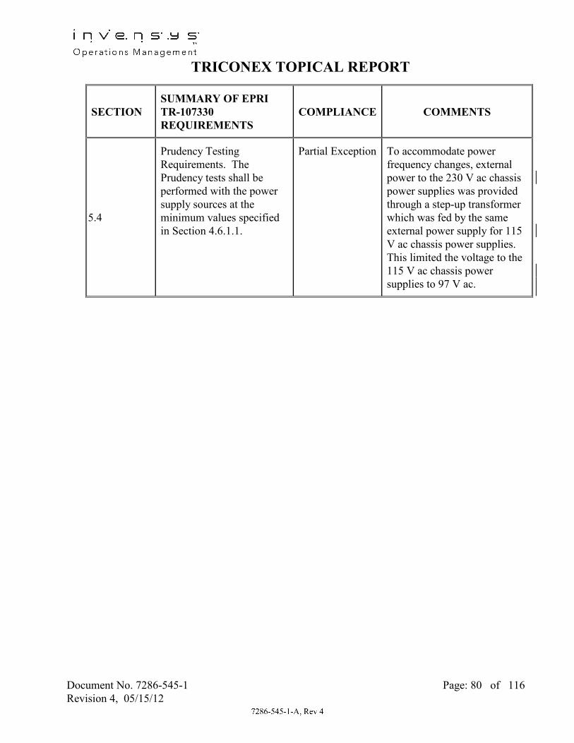
TRICONEX TOPICAL REPORT
Document No. 7286-545-1 Page: 80 of 116 Revision 4, 05/15/12
SECTION SUMMARY OF EPRI TR-107330 REQUIREMENTS
COMPLIANCE COMMENTS
5.4
Prudency Testing Requirements. The Prudency tests shall be performed with the power supply sources at the minimum values specified in Section 4.6.1.1.
Partial Exception To accommodate power frequency changes, external power to the 230 V ac chassis power supplies was provided through a step-up transformer which was fed by the same external power supply for 115 V ac chassis power supplies. This limited the voltage to the 115 V ac chassis power supplies to 97 V ac.

TRICONEX TOPICAL REPORT
Document No. 7286-545-1 Page: 81 of 116 Revision 4, 05/15/12
SECTION SUMMARY OF EPRI TR-107330 REQUIREMENTS
COMPLIANCE COMMENTS
5.5
Operability/Prudency Testing Applicability Requirements. As a minimum, Operability and Prudency tests shall be performed: - During acceptance testing: Operability – All, Prudency – All - During environmental testing: Operability – All, Prudency – All - During seismic testing: Operability – All, Prudency – All - After seismic testing: Operability – All, Prudency – None - During EMI/RFI testing: Operability – All except analog I/O checks, Prudency – Only burst of events test - After ESD testing: Operability – All, Prudency – None
Partial Exception Due to short duration of seismic SSE tests, and special set-up required for EMI/RFI tests, it is not practicable to perform Operability and Prudency tests at those times. The testing complied with the other requirements of Section 5.5.
5.6
Application Software Objects Acceptance (ASOA) Testing. Requirements for ASOA testing.
Exception See Table Section 5.2.A

TRICONEX TOPICAL REPORT
Document No. 7286-545-1 Page: 82 of 116 Revision 4, 05/15/12
SECTION SUMMARY OF EPRI TR-107330 REQUIREMENTS
COMPLIANCE COMMENTS
6.2.1.E
Power Supplies. The test specimen shall include the power supplies needed to meet the TR requirements. Additional resistive loads shall be placed on each power supply output so that the power supply operates at rated conditions.
Exception The Tricon design does not allow for adding resistive load on the power supplies without altering design and operation. To demonstrate significant power supply loading, one chassis of the test specimen was fully populated with one module in each slot.
6.2.1.F
Dummy Modules. Dummy modules shall be used to fill all remaining slots in the main chassis and at least one expansion chassis. The dummy modules shall provide a power supply and weight load approximately equal to an eight point discrete input module.
Exception Seismic Balance Modules (SBMs) were installed in two test specimen chassis to increase the weight loading to that representative of a fully module populated chassis. Dummy modules did not provide a load on the power supplies.
6.3.2
EMI/RFI Test Requirements. EMI/RFI testing to be performed as described in Section 4.3.7. Susceptibility tests to be performed at 25%, 50%%, and 75% of specified levels in addition to the specified levels.
Exception EMI/RFI testing performed per R.G. 1.180, R1. Testing performed at levels lower than specified levels only as needed to establish susceptibility threshold.

TRICONEX TOPICAL REPORT
Document No. 7286-545-1 Page: 83 of 116 Revision 4, 05/15/12
SECTION SUMMARY OF EPRI TR-107330 REQUIREMENTS
COMPLIANCE COMMENTS
6.3.2.1
EMI/RFI Mounting Requirements. Test specimen shall be mounted on a non-metallic surface six feet above floor with no secondary enclosure. PLC shall be grounded per manufacturer’s recommendations.
Exception Due to space limitations of NTS Labs EMI/RFI chamber, the test specimen was mounted less than six feet above the floor. The test specimen was mounted in a Rittal cabinet with sides and doors removed. Cabinets provided no significant shielding.
6.3.5.1
Surge Withstand Test Mounting Requirements. Test specimen shall be mounted on a non-metallic surface six feet above floor with no secondary enclosure. PLC shall be grounded per manufacturer’s recommendations.
Exception Due to space limitations of NTS Labs EMI/RFI chamber, the test specimen was mounted less than six feet above the floor. The test specimen was mounted in a Rittal cabinet with the sides and doors removed.
6.3.6
Class 1E to Non-1E Isolation Testing. Test specimen shall be mounted on a non-metallic surface six feet above floor with no secondary enclosure. PLC shall be grounded per manufacturer’s recommendations.
Exception Due to space limitations of NTS Labs EMI/RFI chamber, the test specimen was mounted less than six feet above the floor. Test The test specimen was mounted in a Rittal cabinet with the sides and doors removed.
6.4.4.G
ASOA Test Compliance. Results shall be evaluated for compliance to Section 5.6 requirements.
Exception ASOA testing not performed.

TRICONEX TOPICAL REPORT
Document No. 7286-545-1 Page: 84 of 116 Revision 4, 05/15/12
2.5 REFERENCES
2.5.1 NUREG-800; Standard Review Plan, Section 7.0, “Instrumentation and Controls – Overview of Review Process,” Rev. 5, March 2007
2.5.2 NUREG/CR-6241, “Using Commercial-Off-the-Shelf (COTS) Software in High-Consequence Safety Systems,” November 10, 1995
2.5.3 NUREG/CR-6463, “Review Guidelines on Software Languages for Use in Nuclear Power Plant Safety Systems,” October 1997
2.5.4 U.S. Nuclear Regulatory Commission Regulatory Guide 1.180, Revision 1, “Guidelines for Evaluating Electromagnetic and Radio-Frequency Interference in Safety-Related Instrumentation and Control Systems,” October 2003
2.5.5 EPRI Report, TR-107330, “Generic Requirements Specification for Qualifying Commercially Available PLC for Safety-Related Applications in Nuclear Power Plants”
2.5.6 EPRI Report TR-102323-R1, “Guidelines for Electromagnetic Interference Testing in Power Plants”
2.5.7 IEEE Std. 323-1983, “Standard for Qualifying Class 1E Equipment for Nuclear Power Generating Stations”
2.5.8 IEEE Std. 344-1987, “Recommended Practices for Seismic Qualification of Class 1E Equipment for Nuclear Power Generating Stations”
2.5.9 IEEE Std. 381-1977, “Standard Criteria for Type Tests of Class 1E Modules Used in Nuclear Power Generating Stations”
2.5.10 IEEE Std. 384-1981, “IEEE Standard Criteria for Independence of Class 1E Equipment and Circuits”
2.5.11 IEEE Std. 7-4.3.2-2003, “IEEE Standard Criteria for Digital Computers in Safety Systems of Nuclear Power Generating Stations”
2.5.12 IEEE Std. 1012-1998, “IEEE Standard for Software Verification and Validation Plans"
2.5.13 IEEE Std. 323-2003, “IEEE Standard for Qualifying Class 1E Equipment for Nuclear Power Generating Stations.”
2.5.14 IEC 61000-4-2 “Electromagnetic Compatibility (EMC), Part 4-2: Testing and Measurement Techniques, Electrostatic Discharge Immunity Test,” April 2001

TRICONEX TOPICAL REPORT
Document No. 7286-545-1 Page: 85 of 116 Revision 4, 05/15/12
2.5.15 IEC 61000-4-3, “Electromagnetic Compatibility (EMC), Part 4-3: Testing and Measurement Techniques, Radiated, Radio-Frequency, Electromagnetic Field Immunity Test,” September 2002
2.5.16 IEC 61000-4-4, “Electromagnetic Compatibility (EMC), Part 4-4: Testing and Measurement Techniques, Electrical Fast Transient/Burst Immunity Test,” 2004
2.5.17 IEC 61000-4-5, “Electromagnetic Compatibility (EMC), Part 4-5: Testing and Measurement Techniques, Surge Immunity Test,” April 2001
2.5.18 IEC 61000-4-6, “Electromagnetic Compatibility (EMC), Part 4-6: Testing and Measurement Techniques, Immunity to Conducted Disturbances, Induced by Radio-Frequency Fields,” November 2004
2.5.19 IEC 61000-4-8, “Electromagnetic Compatibility (EMC), Part 4-8: Testing and Measurement Techniques, Power Frequency Magnetic Field Immunity Test,” March 2001
2.5.20 IEC 61000-4-9, “Electromagnetic Compatibility (EMC), Part 4-9: Testing and Measurement Techniques, Pulse Magnetic Field Immunity Test,” March 2001
2.5.21 IEC 61000-4-10, “Electromagnetic Compatibility (EMC), Part 4-10: Testing and Measurement Techniques, Damped Oscillatory Magnetic Field Immunity Test,” March 2001
2.5.22 IEC 61000-4-12, “Electromagnetic Compatibility (EMC), Part 4-12: Testing and Measurement Techniques, Oscillatory Waves Immunity Test,” April 2001
2.5.23 IEC 61000-4-13, “Electromagnetic Compatibility (EMC), Part 4-13: Testing and Measurement Techniques, Harmonics and Interharmonics Including Mains Signaling at A.C. Power Port, Low Frequency Immunity Tests,” March 2002
2.5.24 IEC 61000-4-16, “Electromagnetic Compatibility (EMC), Part 4-16: Testing and Measurement Techniques, Test for Immunity to Conducted, Common Mode Disturbances in the Frequency Range 0 Hz to 150 kHz,” July 2002
2.5.25 IEC 61784-3, “Industrial Process Measurement and Control – Digital Communications,” July 2005
TRICONEX DOCUMENTS
2.5.26 Triconex Quality Assurance Manual (QAM)
2.5.27 Triconex Quality Procedures Manual (QPM)

TRICONEX TOPICAL REPORT
Document No. 7286-545-1 Page: 86 of 116 Revision 4, 05/15/12
2.5.28 Triconex Engineering Department Manual (EDM)
2.5.29 Tricon Product Guide, Triconex Document No. 9791007-013
2.5.30 Tricon Planning and Installation Guide, Triconex Document No. 9720077-008
2.5.31 Differences between the Tricon V9.5.3 System and the Tricon V10.2.1 System, Invensys Document No. NTX-SER-09-05
2.5.32 Triconex Development Processes for PLDs in Nuclear Qualified Products, Invensys Document No. NTX-SER-09-06
2.5.33 Nuclear System Integration Program Manual, Invensys Document No. NTX—SER-09-021
2.5.34 Tricon V10 Conformance to Regulatory Guide 1.152, Invensys Document No. NTX-SER-10-14
2.5.35 Tricon Applications in Nuclear Reactor Protection Systems – Compliance with NRC ISG-2 and ISG-4, Invensys Document No. NTX-SER-09-10
2.5.36 Safety Evaluation Report (SER) Maintenance Process, Invensys Document No. NTX-SER-09-20
TRICONEX NUCLEAR QUALIFICATION PROJECT DOCUMENTS
2.5.37 Triconex Nuclear Qualification Quality Plan, Triconex Document No. 9600164--002.
2.5.38 Master Test Plan, Triconex Document No. 9600164-500
2.5.39 Master Configuration List, Triconex Document No. 9600164-540
2.5.40 Software QA Plan, Triconex Document No. 9600164-537
2.5.41 Tricon System Description, Triconex Document No. 9600164-541
2.5.42 Equipment Qualification Summary Report, Triconex Document No.. 9600164--545
2.5.43 Function Diagrams, Triconex Drawing Nos. 9600164-500 to 515
2.5.44 Wiring Schedule, Triconex Drawing No. 9600164-700
2.5.45 Test System Wiring Drawings, Triconex Drawing Nos. 9600164-100 to 300
2.5.46 Setup and Checkout Test Procedure, Triconex Document No. 9600164-502

TRICONEX TOPICAL REPORT
Document No. 7286-545-1 Page: 87 of 116 Revision 4, 05/15/12
2.5.47 Operability Test Procedure, Triconex Document No. 9600164-503
2.5.48 Prudency Test Procedure, Triconex Document No. 9600164-504
2.5.49 Radiation Test Procedure, Triconex Document No. 9600164-511
2.5.50 Environmental Test Procedure, Triconex Document No. 9600164-506
2.5.51 Seismic Test Procedure, Triconex Document No. 9600164-507
2.5.52 Surge Withstand Test Procedure, Triconex Document No. 9600164-508
2.5.53 Class 1E to Non-1E Isolation Test Procedure, Triconex Document No. 9600164-509
2.5.54 EMI/RFI Test Procedure, Triconex Document No. 9600164-510
2.5.55 Pre-qualification Operability Test Report, Triconex Document No. 9600164-560
2.5.56 Environmental Test Report, Triconex Document No. 9600164-525
2.5.57 Seismic Test Report, Triconex Document No. 9600164-526
2.5.58 EMI/RFI Test Report, Triconex Document No. 9600164-527
2.5.59 Surge Test Report, Triconex Document No. 9600164-528
2.5.60 Class 1E to Non-1E Isolation Test Report, Triconex Document No. 9600164-529
2.5.61 Performance Proof Operability Test Report, Triconex Document No. 9600164-566
2.5.62 Reliability/Availability Study for Tricon PLC Controller, Triconex Document No. 9600164-532
2.5.63 Failure Modes and Effects Analysis (FEMA) for TRICON V10 PLC, Triconex Document No. 9600164-531
2.5.64 Tricon System Accuracy Specifications, Triconex Document No. 9600164-534
2.5.65 Software Qualification Report, Triconex Document No. 9600164-535
2.5.66 TSAP Software Requirements Specification, Triconex Document No. 9600164-517
2.5.67 TSAP Software Design Description, Triconex Document No. 9600164-518
2.5.68 TSAP Software V&V Plan, Triconex Document No. 9600164-513

TRICONEX TOPICAL REPORT
Document No. 7286-545-1 Page: 88 of 116 Revision 4, 05/15/12
2.5.69 TSAP Final V&V Report, Triconex Document No. 9600164-537
2.5.70 Software Traceability Analysis, Triconex Document No. 9600164-720
2.5.71 TÜV-Rheinland Microelectronic and Process Automation, “Type Approval for the Tricon Triple Modular Redundant (TMR) Controller Tricon,” Report No. 945/EL 336/91, April 19, 1991
2.5.72 TÜV-Rheinland Microelectronic and Process Automation, “Type Approval of TriconVersion10.2.1,” Report No. 968/EZ 105.06/06, October 31, 2006
2.5.73 EFT Test Procedure, Triconex Document No. 9600164-514
2.5.74 ESD Test Procedure, Triconex Document No. 9600164-512
2.5.75 Pre-Qualification Prudency Test Report, Triconex Document No. 9600164-670
2.5.76 Radiation Test Report, Triconex Document No. 9600164-533
2.5.77 EFT Test Report, Triconex Document No. 9600164-521
2.5.78 ESD Test Report, Triconex Document No. 9600164-522
2.5.79 Performance Proof Prudency Test Report, Triconex Document No. 9600164-573
2.5.80 Critical Digital Review, Triconex Document No. 9600164-539
2.5.81 Cable Similarity Analysis, Triconex Document No. 9600164-538
2.5.82 Maximum Response Time Calculations, Triconex Document No. 9600164-731
2.5.83 Performance Proof Operability Test Report, Triconex Document No. 9600164-566

TRICONEX TOPICAL REPORT
Document No. 7286-545-1 Page: 89 of 116 Revision 4, 05/15/12
3.0 DIFFERENCES BETWEEN V9.5.3 AND V10.2.1 SYSTEMS
3.1 BACKGROUND
This section provides an overview of the basic hardware and software differences between the Tricon V9.5.3 system (the current V9 system identified in the existing SER) and the Tricon V10.2.1 system. A more complete and detailed discussion of the platform differences between V9.5.3 to V10.2.1 systems is provided in Triconex document NTX-SER-09-05, “Differences between the Tricon V9.5.3 System and the Tricon V10.2.1 System” (Reference 2.5.31).
As noted in section 2.0, Invensys initiated the Tricon V10.2.1 Nuclear Qualification Upgrade Project to address the contingencies identified for V9.5.3 in Triconex Topical Report 7286-545-1-A, Qualification Summary Report and the NRC Safety Evaluation Report (SER) dated December 12, 2001 (ADAMS Accession Number ML013470433). NRC staff noted that the Tricon PLC system did not fully meet the guidance of TR-107330 for seismic, EMI/RFI conducted and radiated emissions, surge withstand, and ESD withstand, requiring the nuclear facility engineering staff to verify that reported results envelop the specific facility application. Recognizing that such requirements increase facility contingencies, Invensys initiated modifications of the Tricon platform to elevate its performance to that required in EPRI TR-107330 and the recently issued R.G. 1.180, Revision 1. In addition to EMC hardening of components, Invensys also introduced new processors and features, which required evaluation, verification and validation testing. The Tricon V10.2.1 system added the following new modules:
• A new Main Processor - Model 3008N • New SMT-based “Next Generation I/O modules” - AI 3721N and DO 3625N • A new Communication Module - TCM 4325AN (Fiber Optic)
Upgraded/redesignated versions of existing modules: • A new Analog Input Module - AO 3805HN (4-20 mA) (from AO 3805EN) • A new Pulse Input Module - PI 3511N (from PI 3510N) • Existing Through Hole I/O modules converted to SMT modules:
(Form, fit, and function compatible) o 3701N (0-10 VDC) - Through Hole to 3701N2 (0-10 VDC) – SMT o 3501TN 115V AC/DC – Through Hole to 3501TN2 115V AC/DC – SMT o 3502EN 48V AC/DC – Through Hole to 3502EN2 48V AC/DC – SMT o 3503EN 24V AC/DC – Through Hole to 3503EN2 24V AC/DC – SMT
Miscellaneous support hardware units added: • New Remote Extender Modules – RXM 4200N, 4201N • New upgraded Power Supply Modules – PS 8310N2, 8311N2, 8312N2 • New I/O Module termination panels – (various for new modules & EMC levels) • New Signal Conditioners (various to support new modules)

TRICONEX TOPICAL REPORT
Document No. 7286-545-1 Page: 90 of 116 Revision 4, 05/15/12
3.2 SYSTEM ARCHITECTURE & SYSTEM LEVEL DIFFERENCES BETWEEN V9.5.3 & V10.2.1
Section 2 of the V9 SER describes the Tricon V9.5.3 system architecture. The Tricon V10.2.1 system architecture is the same as that of the previously qualified Tricon V9.5.3 system. Figure 3-1, also in the SER, shows the Triple Modular Redundant (TMR) architecture of all Tricon systems:
Figure 3-1: Triple Modular Redundant (TMR) architecture
The TriStation 1131 application programming model architecture for the Tricon V10.2.1 system is the same as that of the previously qualified Tricon V9.5.3 system. The V10.2.1 system is the result of the evolutionary platform improvement of the V9.5.3 system. Since the time the SER was issued, the Tricon V9.5.3 has undergone a number of enhancements as well as maintenance upgrades. The Critical Digital Review (Triconex Report 9600164-539, Reference 2.5.80) provides additional details on the history of upgrades from V9.5.3 to V10.2.1. The stepwise progression of platform change releases between V9.5.3 and V10.2.1 is also described in Reference 2.5.31 (Triconex document NTX-SER-09-05).
3.3 COMPARISON OF V9/V10 DIFFERENCES
Section 1.0 of the V9 SER contains a list of Tricon V9.5.3 modules approved for use in safety-related applications. The SER also contains a table titled “Safety-related Software” in Section 2.2.1 that lists software for each Tricon V9.5.3 module, including version numbers. Tables 3-1 and 3-2 compare Tricon V9.5.3 and V10.2.1 hardware modules and associated software modules. It can be seen that a number of previously qualified modules were deleted from the V10.2.1 qualification. This is primarily a result of replacement by newer modules or changes in market demand.
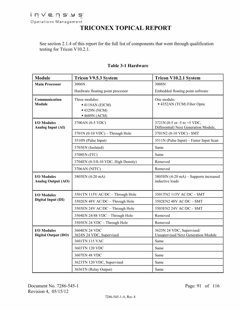
TRICONEX TOPICAL REPORT
Document No. 7286-545-1 Page: 91 of 116 Revision 4, 05/15/12
See section 2.1.4 of this report for the full list of components that went through qualification testing for Tricon V10.2.1.
Table 3-1 Hardware
Module Tricon V9.5.3 System Tricon V10.2.1 System Main Processor 3006N 3008N
Hardware floating point processor Embedded floating point software
Communication Module
Three modules: 4119AN (EICM) 4329N (NCM) 4609N (ACM)
One module: 4352AN (TCM) Fiber Optic
I/O Modules Analog Input (AI)
3700AN (0-5 VDC) 3721N (0-5 or -5 to +5 VDC, Differential) Next Generation Module,
3701N (0-10 VDC) – Through Hole 3701N2 (0-10 VDC) - SMT
3510N (Pulse Input) 3511N (Pulse Input) – Faster Input Scan
3703EN (Isolated) Same
3708EN (ITC) Same
3704EN (0-5/0-10 VDC, High Density) Removed
3706AN (NITC) Removed
I/O Modules Analog Output (AO)
3805EN (4-20 mA) 3805HN (4-20 mA) – Supports increased inductive loads
I/O Modules Digital Input (DI)
3501TN 115V AC/DC – Through Hole 3501TN2 115V AC/DC – SMT
3502EN 48V AC/DC – Through Hole 3502EN2 48V AC/DC – SMT
3503EN 24V AC/DC – Through Hole 3503EN2 24V AC/DC – SMT
3504EN 24/48 VDC – Through Hole Removed
3505EN 24 VDC – Through Hole Removed
I/O Modules Digital Output (DO)
3604EN 24 VDC 3624N 24 VDC, Supervised
3625N 24 VDC, Supervised/ Unsupervised Next Generation Module
3601TN 115 VAC Same
3603TN 120 VDC Same
3607EN 48 VDC Same
3623TN 120 VDC, Supervised Same
3636TN (Relay Output) Same

TRICONEX TOPICAL REPORT
Document No. 7286-545-1 Page: 92 of 116 Revision 4, 05/15/12
Table 3-1 Hardware
Module Tricon V9.5.3 System Tricon V10.2.1 System Remote Extender Modules: Primary Remote
4210N (Single Mode Fiber Optic cable) 4211N (Single Mode Fiber Optic
4200N (Multi Mode Fiber Optic cable) 4201N (Multi Mode Fiber
I/O Module Term Panels
Version 8 Term Panels Version 9 Term Panels (various)
Removed Additional Version 9 Term Panels to support new I/O modules
Signal Conditioners Signal Conditioner (-100 to 100 °C) Pt (7B34-01-1) Signal Conditioner (0 to 100 °C) Pt
(7B34-02-1) Signal Conditioner (0 to 200 °C) Pt
(7B34-03-1) Signal Conditioner (0 to 600 °C) Pt
(7B34-04-1)
Same
Not included Four additional Signal Conditioners: Signal Conditioner (0 to 200 °C)
Pt (7B34-CUSTOM) Signal Conditioner (0 to 600 °C)
Pt (7B34-CUSTOM) Signal Conditioner (0 to 100 mV)
(7B30-02-1) Signal Conditioner (0 to 120 °C)
Cu (7B14-C-02-1)
Power Supplies:
120 V 24 VDC 230 VAC
ASTEC Power Modules Alternate Vicor Power Modules
8310N 8311N
8310N2 8311N2 8312N2
Chassis: Main Expansion Remote Expansion
8110N 8111N 8112N
8110N2 8111N 8112N

TRICONEX TOPICAL REPORT
Document No. 7286-545-1 Page: 93 of 116 Revision 4, 05/15/12
Table 3-2 Software Module Tricon V9.5.3 System
Software Version Tricon V10.2.1 System Software Version
TriStation 1131 Developer’s Workbench (Application Development Software)
V3.1 V4.1.437
Main Processor Software:
Application Processor
I/O Processor COM Processor
TSX 5211 IOC 5212 COM 5206
ETSX 6198 (Build 92) IOCCOM 6054 (Build 92)
Communication Module Software: TCM
Common V9.5.3 COM EICM NCM ACM
Not Applicable ICM 4930 IICX 5276 NCMX 5028 ACMX 5203
TCM 6136 (Build 92) Not Applicable Not Applicable Not Applicable Not Applicable
I/O Module Software AI 3721N Not Applicable AI 6200 (Build 92)
DO 3625N Not Applicable DO 6213 (Build 92) AI 3701N/N2 AI/NITC 4873 AI/NITC 5661 IAI 3703EN EIAI/ITC 5491 EIAI/ITC 5916
ITC 3708EN EIAI/ITC 5491 EIAI/ITC 5916 PI 3510N PI 4559 Not Applicable PI 3511N Not Applicable PI 5647
AO 3805EN/HN EAO 5595 EAO 5897 DI 3501TN/TN2 DI 3502EN /EN2 DI 3503EN/EN2
EDI 5490 EDI 5909
DI 3505EN EDI 5490 Not Applicable DI 3504EN HDI 5499 AI 3704EN HDI 5499
DO 3601TN DO 3607EN EDO 5488 EDO 5781
DO 3604EN EDO 5488 Not Applicable RO 3636TN ERO 5497 ERO 5777 DO 3603TN TSDO 5502 Same DO 3623TN TSDO 5502 TSDO2 5940
DO 3624N TSDO 5502 Not Applicable Remote Extender Modules RXM 3310 Same

TRICONEX TOPICAL REPORT
Document No. 7286-545-1 Page: 94 of 116 Revision 4, 05/15/12
4.0 TRICON V10.5.1 UPGRADE
4.1 INTRODUCTION
Triconex has completed a Nuclear Qualification Program for its Tricon Triple Modular Redundant (TMR) PLC for safety related (1E) applications in nuclear facilities. The qualification program was performed and documented in accordance with NRC-approved EPRI TR-107330, “Generic Requirements Specification for Qualifying a Commercially Available PLC for Safety-Related Applications in Nuclear Power Plants.” Triconex report 9600164-545, “Qualification Summary Report” (Reference 2.5.42) presented the final results of all testing and analyses performed in accordance with this EPRI specification. Section 2.0 of this Topical Report incorporates the summary information of the Qualification Summary Report.
The focus of the qualification effort was Tricon product version V10.2.1, and TriStation V4.1.437, which were the prevailing versions being marketed at the time the qualification project was being organized. As with any high-tech product, during the extended period of qualification testing and evaluation, the Tricon products continued to evolve such that upgraded versions beyond V10.2.1 and V4.1.437 are now being manufactured and provided to industry. For business reasons, it is now desired to obtain NRC approval of the current Tricon product offering, specifically Tricon V10.5.1 and its associated support software.
4.2 PURPOSE
All data pertaining to testing and analysis of Tricon V10.2.1 have been provided to the NRC for review. The purpose of this Section of the report is to provide a listing of any pertinent differences between the V10.2.1 product discussed in section 2.0 and the current product upgrades (represented by V10.5.1). A discussion of impact to qualification testing already completed is also provided. This additional information is provided for the NRC’s consideration for inclusion in the SER approval.
4.3 DISCUSSION
No new hardware modules have been added since V10.2.1, i.e., the module listings and hardware descriptions applicable to V10.5.1 are the same as in section 2.1.4 of this report. Routine component and board changes to maintain production needs are ongoing and are reviewed by the Configuration Control Board (CCB) in accordance with Triconex Appendix B QA procedures. This review confirms that no significant changes have been made to modules or which would adversely affect performance specifications or qualification characteristics (e.g. seismic, environmental, electrical, etc.) as specified in EPRI TR 107330.

TRICONEX TOPICAL REPORT
Document No. 7286-545-1 Page: 95 of 116 Revision 4, 05/15/12
V10.5.1 essentially represents the further evolutionary upgrades and bug fixes made to platform software since V10.2.1 was released. Triconex document NTX-SER-09-05 (Reference 2.5.31) provides a development tree and table showing the stepwise progression of platform change releases between V9.5.3 and V10.2.1. Figure 4-1 provides an update to this platform history to reflect the further progression of operating software from V10.2.1 to V10.5.1. Table 4-1 shows the software differences between V10.2.1 and subsequently issued Versions (V10.2.2, V10.2.4, V10.5, and V10.5.1) that have been evaluated and qualified for nuclear use (placed on the NQEL) in accordance with Triconex QA procedures. As seen in Table 4-1, there are five software modules in V10.5.1 that are different from the modules qualified for the V10.2.1 release, i.e.:
ETSX 6271 (versus ETSX 6198) TCM 6276 (versus TCM 6136) AI 6256 (versus AI 5661) DO 6255 (versus DO 6213) TSDO/HVDO 6273 (versus TSDO 5502)
The interim revisions between V10.2.1 and V10.5.1 (i.e., V10.3, V10.4, V10.4.1, and V10.4.2) in the development tree shown in Figure 4-1 have not been released for use in nuclear modules. However, any changes in these releases affecting V10.5.1 operating software modules were reviewed to assure that these revisions had no negative impact on V10.5.1 software integrity. A discussion of each of these interim (non-nuclear) releases is provided in Section 4.3.1.5. In addition, the TriStation 1131 programming software revision level for Tricon V10.5.1 is different (currently at TriStation 1131 V4.7.0). Associated supporting software continues to evolve to address platform changes and maintenance issues. Qualification evaluations have determined that the routine product upgrades have not altered the critical characteristics of the product, i.e., current modules have the same functional and environmental characteristics as the V10.2.1 Test Specimen (or better).

TRICONEX TOPICAL REPORT
Document No. 7286-545-1 Page: 96 of 116 Revision 4, 05/15/12
Primary Release ContentDevelopment Path for V10.2.1 and Subsequent Software Upgrades to V10.5.1 Release
9.6
9.6.1
9.6.2
9.7
9.6.3 9.7.1
9.8
9.9
9.9.1
9.10
9.9.2
9.10.19.9.3
9.6.4 9.7.2 9.8.1
10
10.0.2
10.1
10.2
10.2.1
10.3
10.2.2
10.3.110.2.3
10.2.4
10.4
10.4.1
10.4.2
10.5 Bug fixes (multiple), ETSX6271, TCM6272, HVDO6273
Bug fix, AI6256, DO6255
Bug fix, AI6254, DO6253
BPAO (non nuclear model) (no impact to nuclear SW)
TCM B (non nuclear), ETSX6236, TCM6241, HVDO6142
Next Generation AI (NGAI)
Bug fix
TCM (non nuclear version)
Bug fix
Bug fix
Bug fix
Bug fix
Bug fix
Bug fix
Bug fix
Bug fix
New Main Processor 3008
TCM A (nuclear version)
Next Generation DO (NGDO)
(Upgrade to V10.5.1)
Bug fix
(V10.2.1 Tree)
* = Nuclear Qualified Release
*
* *
*
10.5.1 * Bug fix, TCM6276
Figure 4-1: V10.2.1 to V10.5.1 Software Development Tree – Evolutionary Changes

TRICONEX TOPICAL REPORT
Document No. 7286-545-1 Page: 97 of 116 Revision 4, 05/15/12
Table 4-1: V10.5 Module Software Development History – Changes in Nuclear Released (NQEL) Software
TYPE IDENTIFICATION VERSION (for V10.2.1)
VERSION (for V10.2.2)
VERSION (for V10.2.4)
VERSION (for V10.5)
VERSION (for V10.5.1)
USED IN
Main Processors ETSX 6198 6198 6198 6271 6271* 3008N
IOCCOM 6054 6054 6054 6054 6054 3008N
Communication Module
TCM 6136 6136 6136 6272 6276* 4352AN
I/O Modules
AI/NITC 5661 5661 5661 5661 5661 3701N2
EIAI/ITC 5916 5916 5916 5916 5916 3703EN(AI), 3708EN (TC)
AI 6200 6200 6256 6256* 6256* 3721N
DO 6213 6213 6255 6255* 6255* 3625N
PI 5647 5647 5647 5647 5647 3511N
EDI 5909 5909 5909 5909 5909 3501TN2, 3502EN2, 3503EN2
EAO 5897 5897 5897 5897 5897 3805HN
EDO 5781 5781 5781 5781 5781 3601TN, 3607EN
ERO 5777 5777 5777 5777 5777 3636TN
TSDO/HVDO 5502 6142 6142 6273 6273* 3603TN
TSDO2 5940 5940 5940 5940 5940 3623TN
RXM 3310 3310 3310 3310 3310 4200N, 4201N
Application Program Development Software
TriStation 1131, Developer’s Workbench Suite
4.1.437
4.1.437
4.1.437
4.6.134
4.7.0*
TriStation Workstation
(Bold=new revision released; * = V10.5.1 Software different from V10.2.1)

TRICONEX TOPICAL REPORT
Document No. 7286-545-1 Page: 98 of 116 Revision 4, 05/15/12
4.3.1 Tricon Firmware Changes
4.3.1.1 Upgrade Tricon version from V10.2.1 to V10.2.2
The V10.2.2 incorporates the latest revised TSDO firmware for the 3603TN module. Based on a Product Discrepancy Report and a Technical Advisory Bulletin (TAB), a firmware maintenance update was made to correct a condition of random Output Voter Diagnostic faults on certain PCB board levels.
4.3.1.1.1 Detailed Review of Changes
No additional hardware is being qualified. This change provides newer firmware for the 3603TN Module, which incorporates resolution to the TAB. Only the 3603TN firmware was changed in V10.2.2. Specifically, V10.2.2 consists of a patch to the TSDO 5502 firmware used for the 3603TN, released as the HVDO 6142. Firmware changes were developed and implemented in accordance with EPP 9100135-001. Verification and validation activities were performed in accordance with V&V Plans 9600195-001 and 9600211-001. Firmware was validated as part of V9.52 as documented in the V&V Test Report dated 9/17/2007 and in the 3603T (HVDO) System and I/O Functional Test Report dated 9/17/07.
The new firmware (HVDO 6142) replacing the TSDO 5502 was released together with the V10.2.2 Software Release Definition 6200003-211.
4.3.1.1.2 Impact of Differences on Tricon Qualification
The upgrade to existing qualified 3603TN firmware fixed the problem noted in PDR 2028 and maintained its existing required functionality. The SRD confirms continuing compatibility with the same Tricon modules and other existing software. No functional differences in specified performance or properties were made to the Tricon for V10.2.2.
4.3.1.1.3 Conclusion
It is concluded that this firmware maintenance fix did not introduce any adverse changes to the Tricon system properties or performance. V10.2.2 is considered equivalent to previously qualified V10.2.1 in all aspects of its qualified characteristics.
All software changes were developed in accordance with Triconex Engineering procedures under the Triconex Appendix B QA program. Changes have been provided to and accepted by TÜV Rheinland, in accordance with procedure requirements.
Firmware HVDO 6142 and V10.2.2 are considered to be qualified for nuclear safety related (Class 1E) applications.

TRICONEX TOPICAL REPORT
Document No. 7286-545-1 Page: 99 of 116 Revision 4, 05/15/12
4.3.1.1.4 References
6200003-211 Software Release Definition (SRD) – V10.2.2 9791006-143 TAB #143 9100135-001 EPP for 3603T Module Firmware Fix 9100136-001 Change Impact Analysis – High Voltage TSDO Module 3603T Firmware Fix 9600195-001 Tricon V9.52 V&V Plan 9600211-001 3603T (HVDO) Backward Compatibility Software V&V Plan V9.52 V&V Test Report, dated 9/17/07 3603T HVDO System and I/O Functional Test Report, dated 9/17/07 TUV Certification dated 6/22/08
4.3.1.2 Upgrade Tricon version from V10.2.2 to V10.2.4
The V10.2.4 incorporates the latest revised DO firmware for the 3625N module and AI firmware for the 3721N module. Based on a Product Alert Notice (PAN), a firmware maintenance update was made to correct a condition of the NGIO Core which does not Fault the module when a leg goes down.
4.3.1.2.1 Detailed Review of Changes
No additional hardware is being qualified. This change provides newer firmware for the 3625N and 3721N Modules, which incorporates resolution to the PAN. Only the 3625N and 3721N firmware were changed in V10.2.4. Specifically, V10.2.4 consists of a recompile to the DO 6213 firmware used for the 3625N, released as the DO 6255, and the AI 6200 firmware used for the 3721N, released as AI 6256. Firmware changes were developed and implemented in accordance with EPP 9100234-001. Verification and validation activities were performed in accordance with V&V Plans 9600168-600 and 9100246-001. Firmware was validated as part of V10.2.4 as documented in the V&V Test Report dated 01/19/2009, which includes a system functional test.
The new firmware (DO 6255) replacing the DO 6213 and (AI 6256) replacing the AI 6200 were released together with the V10.2.4 Software Release Definition 6200003-217.
4.3.1.2.2 Impact of Differences on Tricon Qualification
The upgrade to existing qualified 3625N and 3721N firmware fixed the problem noted in the PAN and maintained their existing required functionality. The SRD confirms continuing compatibility with the same Tricon modules and other existing software. No functional differences in specified performance or properties were made to the Tricon for V10.2.4.

TRICONEX TOPICAL REPORT
Document No. 7286-545-1 Page: 100 of 116 Revision 4, 05/15/12
4.3.1.2.3 Conclusion
It is concluded that this firmware maintenance fix did not introduce any adverse changes to the Tricon system properties or performance. V10.2.4 is considered equivalent to previously qualified V10.2.2 in all aspects of its qualified characteristics.
All software changes were developed in accordance with Triconex Engineering procedures under the Triconex Appendix B QA program. Changes have been provided to and accepted by TUV Rheinland, in accordance with procedure requirements.
Firmware DO 6255, AI 6256 and V10.2.4 are considered to be qualified for nuclear safety related (Class 1E) applications.
4.3.1.2.4 References
6200003-217 Software Release Definition (SRD) – V10.2.4 9791010-019 PAN #19 9100234-001 EPP for Tricon V10.2.4 9100234-002 Change Impact Analysis – Tricon V10.2.4 9100246-001 Tricon V10.2.4 V&V Plan 9600168-600 NGIO Software Verification and Validation Plan (SVVP) V10.2.4 V&V Test Report, dated 1/19/09 TUV Certification dated 3/16/09
4.3.1.3 Upgrade Tricon version from V10.2.4 to V10.5
The V10.5 provides a more current version of Tricon System that incorporates a collection of enhancements to operating software and error corrections, as tabulated in SRD 6200003-220.
4.3.1.3.1 Detailed Review of Changes
No additional hardware is being qualified. This change provides newer firmware for the 3008N, 3603TN, and 4352AN Modules, which incorporate resolutions to various PDR’s. Changes included correction of conditions noted in TABs 166 and 170. V10.5 also provided common firmware for TCM versions 4352A and 4352B to support alternate board components. Due to the large number of PDRs encompassed in the 10.5 update, other specific changes are not described here, but are tabulated in Software Release Definition (SRD) 6200003-220. Firmware changes were developed and implemented in accordance with V10 EPP 9100218-001. Verification and validation activities were performed in accordance with V&V Plans referenced below. Firmware was validated as documented in the V&V Test Reports listed. V10.5 was approved and released by the Change Control Board (CCB) on 8/13/09.

TRICONEX TOPICAL REPORT
Document No. 7286-545-1 Page: 101 of 116 Revision 4, 05/15/12
Table 4-2 provides a summary of affected firmware releases between V10.2.4 and V10.5.
Table 4-2: Affected Firmware Releases
Tricon Firmware Versions
Firmware module Used In: V10.2.4 V10.5
ETSX 3008N 6198 6271
TCM 4352AN 6136 6272
TSDO/HVDO 3603TN 6142 6273
ETSX 6271, TCM 6272, TSDO/HVDO 6273
ETSX 6271, TCM 6272, and TSDO/HVDO 6273 were released in the V10.5 update in August, 2009
• Software Release Definition (SRD) for V10.5, 6200003-220 Reference documents:
• Tricon V10.5 Validation Plan 9600310-001 • V10.5 Validation and Verification Report
Description of change:The ETSX, TCM, and TSDO/HVDO firmware modules were revised to fix several PDRs affecting the 3008N, 4352AN, and 3603TN modules (see SRD 6200003-220 for details).
ETSX 6271, TCM 6272, TSDO/HVDO 6273 were validated as part of the Tricon V10.5 Verification & Validation Plan 9600310-001. This plan included the validation and verification requirements for changes made to the ETSX, TCM, and TSDO/HVDO firmware. The firmware was released in V10.5 per SRD 6200003-220. The results of the V & V are documented in the Tricon V10.5 Validation and Verification Report.
Validation:
4.3.1.3.2 Impact of Differences on Tricon Qualification
None. The functional characteristics of previously qualified revisions of the Firmware: ETSX, TCM, and TSDO/HVDO have not been changed. This was confirmed in validation testing. Maintenance release V10.5 removed previously identified errors and/or provided product enhancements for added functionality in the operating and
Functional Characteristics

TRICONEX TOPICAL REPORT
Document No. 7286-545-1 Page: 102 of 116 Revision 4, 05/15/12
programming software.

TRICONEX TOPICAL REPORT
Document No. 7286-545-1 Page: 103 of 116 Revision 4, 05/15/12
None. No hardware or printed circuit board changes were made. No physical characteristics changed that would affect the radiation, environmental, seismic, or electrical qualification. Revised software is compatible with all associated hardware.
Physical Characteristics:
No differences. All software changes were developed, tested, and released in accordance with the Triconex 10CFR50 Appendix B QA program. Changes have been provided to and approved by TUV Rheinland, in all cases.
Quality Characteristics:
Based on the above, it is concluded that changes made in V10.5 did not introduce any changes to the TRICON system’s
• Safety Function • Acceptance Criteria (Performance Specifications) • Dielectric Stress Levels • Mechanical Stresses, or • Postulated Service Conditions
4.3.1.3.3 Conclusion
V10.5 is considered equivalent to V10.2.4, which was previously qualified 1E. No changes were made to the basic functionality or reliability. Triconex has no reason to believe that any of the changes made from V10.2.4 to V10.5 invalidate the findings and results of the generic qualification of the Tricon in accordance with EPRI TR-107330.
No additional qualification steps are required to consider Tricon V10.5 qualified. TRICON V10.5 is considered to be qualified for nuclear safety related (Class 1E) application.
4.3.1.3.4 References
EPP 9100218-001 SRD for V10.5, 6200003-220 Tricon V10.5 Validation Plan 9600310-001 V10.5 Validation and Verification Report TAB 166 TAB 170 TUV Certification for V10.5, dated 7/22/09

TRICONEX TOPICAL REPORT
Document No. 7286-545-1 Page: 104 of 116 Revision 4, 05/15/12
4.3.1.4 Upgrade Tricon version from V10.5 to V10.5.1
Maintenance Release V10.5.1 provides a more current version of Tricon System that incorporates an enhancement to the operating software as tabulated in SRD 6200003-221. This is considered a minor change to fix an observed anomaly (ref TAB 181).
4.3.1.4.1 Detailed Review of Changes
No additional hardware is being qualified. This change provides newer firmware for the 4352AN and 4352BN Modules, which incorporates resolutions to a PDR. Changes included correction of conditions noted in TAB 181. V10.5.1 corrected a condition with a TSAA Protocol BIN broadcast issue. Firmware changes were developed and implemented in accordance with V10.5.1 EPP 9100315-001. Verification and validation activities were performed in accordance with V&V Plans referenced below. Firmware was validated as documented in the V&V Test Reports listed. V10.5.1 was approved and released by the Change Control Board (CCB) on 6/16/10.
TCM 6276
TCM 6276 was released in the V10.5.1 update in June, 2010
• Software Release Definition (SRD) for V10.5.1, 6200003-221 Reference documents:
• Tricon V10.5.1 Validation Plan 9600310-001 • V10.5.1 Validation and Verification Report
Description of change:The TCM firmware modules were revised to fix a PDR affecting the 4352AN and 4352BN modules (see SRD 6200003-221 for details).
TCM 6276 was validated as part of the Tricon V10.5.1 Verification & Validation Plan 9600310-001. This plan included the validation and verification requirements for changes made to the TCM firmware. The firmware was released in V10.5.1 per SRD 6200003-221. The results of the V & V are documented in the Tricon V10.5.1 Validation and Verification Report.
Validation:
4.3.1.4.2 Impact of Differences on Tricon Qualification
Functional Characteristics
None. The functional characteristics of previously qualified revisions of the Firmware: TCM has not been changed. This was confirmed in validation testing. Maintenance release V10.5.1 removed a previously identified error in the operating and programming software.

TRICONEX TOPICAL REPORT
Document No. 7286-545-1 Page: 105 of 116 Revision 4, 05/15/12
Physical Characteristics:
None. No hardware or printed circuit board changes were made. No physical characteristics changed that would affect the radiation, environmental, seismic, or electrical qualification. Revised software is compatible with all associated hardware.
Quality Characteristics:
No differences. All software changes were developed, tested, and released in accordance with the Triconex 10CFR50 Appendix B QA program. Changes have been provided to and approved by TUV Rheinland, in all cases.
Based on the above, it is concluded that changes made in V10.5.1 did not introduce any changes to the TRICON systems:
• Safety Function • Acceptance Criteria (Performance Specifications) • Dielectric Stress Levels • Mechanical Stresses, or • Postulated Service Conditions
4.3.1.4.3 Conclusion
V10.5.1 is considered equivalent to V10.5, which was previously qualified 1E. No changes were made to the basic functionality or reliability. Triconex has no reason to believe that any of the changes made from V10.5 to V10.5.1 invalidate the findings and results of the generic qualification of the Tricon in accordance with EPRI TR-107330.
No additional qualification steps are required to consider Tricon V10.5.1 qualified. TRICON V10.5.1 is considered to be qualified for nuclear safety related (Class 1E) application.
4.3.1.4.4 References
EPP 9100218-001 SRD for V10.5.1, 6200003-221 Tricon V10.5.1 Validation Plan 9600310-001 V10.5.1 Validation and Verification Report TAB 181 TUV Certification for V10.5.1, dated 6/07/10

TRICONEX TOPICAL REPORT
Document No. 7286-545-1 Page: 106 of 116 Revision 4, 05/15/12
4.3.1.5 Other Releases potentially affecting V10.5.1 Software
The Software development path from V10.2.1 to V10.5.1 shown in Figure 4-1 reflects the release of interim versions 10.3, 10.4, 10.4.1, and 10.4.2. These were commercial releases that were not specifically qualified for nuclear facility applications. However, two of the releases (V10.3 and V10.4.1) made changes to software modules that are used in nuclear qualified V10.5.1 but not described above. Records for these releases were reviewed to confirm that software changes were developed, controlled, and validated accordance with approved EDM development processes.
Release V10.3 was initiated to support new commercial versions of the TCM modules (in addition to the 4352AN). V10.3 included an upgrade to Main Processor software module (ETSX 6236) and Communication Module software module (TCM 6241), both of which were superseded by later V10.5 upgrades ETSX 6271 and TCM 6272, discussed above. V10.3 was approved and released by the Change Control Board (CCB) on 4/26/07. This release was also reviewed and approved by TUV.
• Engineering Project Plan, 9100109-001 Reference documents:
• Software Release Definition (SRD) for V10.3, 6200003-200 • Tricon V10.3 Validation Plan 9600186-001/9600190-001 • V10.3 Validation and Verification Report • V10.3 TUV approval dated 5/14/07
Release V10.4.1 was primarily initiated to support an interim fix to a software bug (PAN 19). This release included an interim upgrade to NGDO software module (DO 6253) and NGAI software module (AI 6254), both of which were superseded by later V10.2.4 upgrades AI 6271 and TCM 6272, discussed above. V10.4.1 was approved and released by the Change Control Board (CCB) on 9/15/08. This release was also reviewed and approved by TUV.
• Engineering Project Plan, 9100227-001 Reference documents:
• 9791010-019, PAN #19 • Software Release Definition (SRD) for V10.4.1, 6200003-214 • Validation Plan/Section 7.0 of 9100227-001 • PAN 19 Validation and Verification Report (V10.4.1/V10.3.1/V10.2.3) • V10.4.1 TUV approval dated 11/12/08
Conclusion: The referenced interim changes to the ETSX, TCM, AI, and DO software modules in V10.3 and V10.4.1 (between V10.2.1 and V10.5.1) were developed, controlled, and validated in accordance with approved EDM procedures, as evidenced in development

TRICONEX TOPICAL REPORT
Document No. 7286-545-1 Page: 107 of 116 Revision 4, 05/15/12
records and TUV approvals, and therefore had no adverse impact on subsequent revisions of these modules in V10.5.1.
4.3.2 TriStation 1131 Changes
TriStation Programming software was upgraded to V4.7.0 as the current version that supports the V10.5.1 platform release. PDR fixes and product enhancements were incorporated, but no basic functional changes were made. Evaluation details and records for TriStation V4.7.0 are on file and available for review and audit. Upgrades were made in accordance with EDM procedures and reviewed by TÜV.
4.3.3 Process Change Review
Changes to the Triconex Quality Assurance program and development processes between V9.5.3 and V10.2.1 were reviewed in document NTX-SER-09-05, “Differences between the Tricon V9.5.3 System and the Tricon V10.2.1 System.” This section reviews changes to processes from V10.2.1 to V10.5.1 (developed during the period of 2006 to 2010) for any impact on the V10.5 software changes described in sections 4.3.1 and 4.3.2 above.
4.3.3.1 QA program and procedures
For the period of 2001 to 2006, the “Differences Document” (NTX-SER-09-05) tabulated the changes to QA Manual (QAM) sections and Quality Procedure Manual (QPM) procedures to demonstrate that the Appendix B QA program continued to be consistent with QA program commitments, i.e., 10CFR50 Appendix B, 10CFR21, and NQA-1-1994. While ongoing procedure revisions occurred as part of the normal Triconex QA program maintenance, reflecting changes in implementation details and ongoing process improvements, the QA program continued to be compliant with nuclear industry commitments. This was independently confirmed by nuclear customer and agency audits over the period of 2001 to 2006. Similarly, during the period from 2006 to 2010 (spanning development of software upgrades to V10.5.1), commitments to nuclear industry QA regulations and standards did not change. This can be seen by comparing the documented QA Program commitments contained in the 2006 version of the QA Manual (rev 029) and the 2009 QA Manual (revision 040). All revisions to the QAM continued to cite 10CFR50 Appendix B, 10CFR21, and NQA-1-1994 as governing regulations and standards. In addition, all QAM revisions contained reference to the Invensys Corporate Nuclear Quality Assurance Manual (IOM-Q2), which commits to the nuclear industry regulations and standards. The current version of IOM-Q2 (Rev 3, 10/23/09) also continues to cite 10CFR50 Appendix B, 10CFR21, and NQA-1-1994 as governing regulations and standards among other international nuclear QA standards as the basis for the IOM Nuclear Quality Assurance Program.

TRICONEX TOPICAL REPORT
Document No. 7286-545-1 Page: 108 of 116 Revision 4, 05/15/12
Continuing compliance with nuclear quality program requirements during the 2006-2010 period was confirmed by internal and external audits, including customer (NUPIC) and NRC audits that reflected continuing Triconex status as an approved nuclear supplier. QA processes and commitments have remained stable and compliant in the period spanning the development and production release of Tricon V10.5.1. Details of individual procedure changes during this period will not be tabulated. However, a change to the Triconex Quality Assurance Program that occurred in 2009 warrants discussion. A restructuring of the QA program document hierarchy was implemented as part of an Invensys management goal to establish consistency in Quality Assurance Programs at the corporate level. Effective August 7, 2009, the Corporate Quality Assurance Manuals IOM-Q1 (ISO 9000) and IOM-Q2 (Invensys Nuclear Quality Assurance Manual) were formally adopted as the Top level QA program documents for Triconex activities. The Triconex QA Manual (QAM) was made redundant by this change and was formally cancelled and superseded by IOM-Q1 and IOM-Q2. Prior to cancellation of the QAM, any significant procedural detail that previously existed in the QAM sections was confirmed to be adequately covered in the following department procedure manuals that implement the Triconex QA program:
• Quality Procedures Manual (QPM) • Manufacturing Department Manual (MDM) • Engineering Department Manual (EDM) • Project Procedures Manual (PPM)
While the document structure underwent a change in 2009, the requirements and process content previously reflected in the QAM remained unchanged. A description and detailed mapping of the Quality System Restructuring Project can be found in the current QPM Manual.
4.3.3.2 Engineering/Software Development Processes
Document NTX-SER-09-05, “Differences between the Tricon V9.5.3 System and the Tricon V10.2.1 System” reviewed Product Development Processes in the EDM for the entire period from 2001 through 2009 (inclusive of EDM Rev 042) and concluded that no reductions or adverse changes to the previously approved development processes were made. This review encompassed the period of development and release of Tricon V10.5. A subsequent review of EDM procedure changes from Rev 042 to current Rev 052 (May 2010) confirmed that, while routine procedure changes were made for process implementation clarifications, enhancements, and audit finding corrective action, no substantial changes to the basic development process elements have occurred during the period of development of Tricon V10.5.1. The Triconex Product Development processes continue to be consistent with previous process methodology, quality standards, and V9 SER commitments for ongoing independent reviews by TÜV.

TRICONEX TOPICAL REPORT
Document No. 7286-545-1 Page: 109 of 116 Revision 4, 05/15/12
4.3.3.3 Conclusion (Process Change Review)
No changes were made to the Quality Assurance or Development processes that reduced commitments or effectiveness of processes affecting the product upgrade from V10.2.1 to V10.5.1.
4.4 CONCLUSION
The Tricon V10.5.1 products and TriStation V4.7.0 Application Software continue to meet EPRI TR 107330 and IEEE requirements for Class 1E service and accurately represent the Tricon Qualification Test results as presented in the V10.2.1 Qualification Summary Report, 9600164-545. Changes made to the Tricon product since V10.2.1 and TriStation 4.1.437 are considered minor and evolutionary and have no adverse effect on qualification program results previously submitted for review.

TRICONEX TOPICAL REPORT
Document No. 7286-545-1 Page: 110 of 116 Revision 4, 05/15/12
5.0 INVENSYS PROCESSES AND POLICIES FOR NUCLEAR PRODUCTS
As a supplement to the Tricon Platform description and product qualification information in this Topical Report, a discussion is provided below on Invensys processes and policies as they relate to nuclear safety related activities. Invensys maintains a strong ongoing commitment to consistency with nuclear industry regulations, standards, and NRC guidance in implementation of nuclear product design, manufacture, and nuclear application project delivery.
Invensys commits to maintaining these programs and policies, based on process elements contained in the governing documents referenced below, as part of the Topical Report. Changes to processes that are not consistent with these documents will be evaluated for impact on the SER and need for topical report revision (see section 5.6).
5.1 MAINTENANCE OF QA AND PRODUCT DEVELOPMENT PROCESSES
5.1.1 Quality Assurance Program
At the time of the V9 Triconex Platform SER (December 2001), Triconex was operating under a 10CFR50 Appendix B Quality Assurance Program. The program had been established and approved by nuclear utility audits in early 1998. The V9 Tricon System, with existing legacy hardware and software, was not fully developed under the Appendix B program, as noted in the SER. However, all nuclear related activities, including hardware and software development, since 1998 have been implemented under 10CFR50 Appendix B controls. The Appendix B nuclear QA program has been maintained since the V9 qualification timeframe as evidenced by continued nuclear utility approvals of Invensys Triconex as a nuclear safety-related system supplier. Further discussion of audits by nuclear utilities (including NUPIC audits) and the NRC is found in Invensys document NTX-SER-09-05, “Differences between the Tricon V9.5.3 System and the Tricon V10.2.1 System,” (Reference 2.5.31). Section 4.0 above reviews the Quality Assurance Program status from V10.2.1 timeframe to V10.5.1 .
All processes listed in this section are contingent on compliance with the Invensys Nuclear Quality Assurance Manual and documented approval of the program by nuclear customer and NRC audits. Any changes to the Quality Assurance Program status shall be evaluated for impact on the SER and the need for topical report revision (see section 5.6).
5.1.2 Product Development Process
The V9 SER documented the NRC’s review of Triconex procedures and process for hardware and software development. The SER concluded that procedures in the Engineering Department Manual (EDM), as part of the Appendix B Quality Assurance Program, were suitable for production of safety related hardware and software, with the caveat that an independent second

TRICONEX TOPICAL REPORT
Document No. 7286-545-1 Page: 111 of 116 Revision 4, 05/15/12
level V&V review (such as by TÜV) would be required for future software to be considered acceptable.
Triconex development processes continue to be equivalent to (or better than) the processes reviewed as part of the V9 Qualification. Product development processes and software development activities continue to be controlled by procedures found in the Engineering Department Manual (EDM). All changes in engineering procedures since the 2001 timeframe were reviewed for any significant changes that may be construed to be a reduction in the rigor or effectiveness development processes as previously reviewed. No reductions were found. To the contrary, an ongoing improvement in process rigor and procedure completeness is evident. Significant improvements in the quality and formality of the EDM procedures have taken place since the SER was issued for Tricon V9.5.3, but no basic changes (reductions in commitment) were made to the design process. For more details, see further discussion of process changes in Invensys document NTX-SER-09-05, “Differences between the Tricon V9.5.3 System and the Tricon V10.2.1 System,” (Reference 2.5.31). Section 4.0 above reviews the Quality Assurance Program status from V10.2.1 timeframe to V10.5.1. Invensys intends to assure that, going forward, the basic Triconex Development Process continues to remain stable and consistent with previously approved processes. However, one aspect of the development process is being changed to reflect the evolution of programmable logic devices (PLDs) such as FPGAs. Historically, Triconex has used relatively simple PLDs in selected Tricon hardware modules and has treated these devices as hardware under its product development and design verification activities. Due to the growth in complexity of these devices, current industry expectation is that PLDs should be treated with a process similar to the software development process rather than the hardware development process, including application of appropriate software standards and techniques. For future nuclear products (developed subsequent to the V10 SER), Triconex will specifically address measures for development of PLDs in a new process distinctively tailored to development of software used in designing and maintaining the PLD. This refinement of process detail is considered to be an improvement. Invensys Triconex document NTX-SER-09-06, “Triconex Development Processes for PLDs in Nuclear Qualified Products,” (Reference 2.5.32) provides a thorough discussion of design control processes historically applied to PLDs in Triconex products and describes planned development program changes related to these devices. Process modifications, where indicated, will be incorporated into EDM 12.00 and supporting EDM hardware development procedures.
EDM procedure 12.00, Product Development Process, is the governing procedure defining the Triconex Product Development Process at the system level. This procedure documents the established process flow, product lifecycle phases (hardware and software) and the primary elements of the NRC approved processes, including the requirement for ongoing review by an independent organization. EDM 12.00 is the development process standard and will be maintained as such going forward.

TRICONEX TOPICAL REPORT
Document No. 7286-545-1 Page: 112 of 116 Revision 4, 05/15/12
Any changes to the process described in EDM 12.00 (or any supporting procedures that deviate from the requirements of this procedure) shall be evaluated for impact on the SER and the need for topical report revision (see Section 5.6).
5.2 INVENSYS PROJECT INTEGRATION PROCESSES
In addition to designing and producing nuclear qualified digital control systems, Invensys develops and delivers entire application projects for nuclear customers under its Project Integration (Delivery) organization. An application project is defined as any project that incorporates standard Tricon products into a fully operational integrated system in accordance with customer specified requirements.
A summary of the administrative controls for Invensys nuclear and commercial application project activities conducted at the Invensys Irvine CA facility is presented in Invensys document NTX-SER-09-21, “Nuclear System Integration Program Manual,” (Reference 2.5.33). A description of the project processes and the basis for implementing project procedures is provided in this document. NTX-SER-09-21 includes a process flowchart of a typical application project implementation.
Project procedures supporting the Nuclear System Integration Program Manual (NSIPM) govern all quality-affecting Project activities performed by personnel at the Irvine facility. The NSIPM implements the requirements of the Invensys Nuclear Quality Assurance Manual, 10CFR50 Appendix B, NQA-1, and applicable Regulatory Guides and industry Standards. Specific standards associated with software activities include, but are not limited to Regulatory Guide 1.168 and IEEE Standards 830 and 1012. The NSIPM may also be used by other Invensys facilities.
The Irvine facility project procedures represented by the NSIPM and their implementation have been audited and deemed to be satisfactory by several outside organizations including nuclear customers, NUPIC, and the Quality & Vendor Branch of the NRC Office of New Reactors (See Inspection Report identified as ADAMS Accession # ML082460540).
The Project Integration Process for all safety related application projects will be implemented utilizing procedures consistent with NTX-SER-09-21 and as audited/approved by nuclear customers.
5.3 SECURITY
The increasing use of computers for various functions at nuclear facilities brings forth new technical challenges that must be addressed in a rigorous and balanced manner. Digital

TRICONEX TOPICAL REPORT
Document No. 7286-545-1 Page: 113 of 116 Revision 4, 05/15/12
computers in nuclear facilities are used in safety-related and non-safety systems, where non-availability or malfunction could affect nuclear safety and continuity of power. Computers are also used to store important and sensitive data, where malfunction could lead to the loss or unavailability of data. As the complexity of these computer systems increases, comprehensive methods to assure computer system dependability and reliability need to be employed.
NRC Regulatory Guide (RG) 1.152, Rev 2, “Criteria for use of Computers in Safety Systems of Nuclear Power Plants,” describes a method that the NRC deems acceptable for complying with regulations for promoting high functional reliability, design quality, and security for the use of digital computers in safety systems for nuclear power plants. In the context of RG 1.152, “security” refers to protective actions taken against a predictable set of non-malicious acts (e.g., inadvertent operator actions or the undesirable behavior of connected systems) that could challenge the integrity, reliability, or functionality of a digital safety system.
As a supplier of digital control systems for safety related applications in nuclear facilities, Invensys is committed to implementing measures to mitigate relevant security risks during the applicable life cycle phases of the digital computer systems. Invensys document NTX-SER-10-14, “Tricon V10 Conformance to Regulatory Guide 1.152,” (Reference 2.5.34), describes the conformance of the V10 Tricon to NRC Regulatory Guide 1.152. NTX-SER-10-14 provides a discussion of the Tricon system characteristics related to security and also contains a conformance table providing details on Tricon V10 conformance to Regulatory Positions 2.1 through 2.5. Triconex commits to maintain conformance to the positions in this document with each new release of the Tricon, in accordance with the process described in NTX-SER-09-20, Invensys Triconex Safety Evaluation Report (SER) Maintenance Process (Reference 2.5.36).
Any significant changes to the provisions described in NTX-SER-10-14 (or procedures deviating from the commitments in this document) shall be evaluated for impact on the SER and need for topical report revision (see Section 5.6).
5.4 DIVERSITY AND DEFENSE-IN-DEPTH ISSUES (ISG-02)
The Invensys position and application philosophy in regard to NRC Interim Staff Guidance ISG-02 and related regulatory standards and guidance is described in Invensys Document NTX-SER-09-10, “Tricon Applications in Nuclear Reactor Protection Systems – Compliance with NRC ISG-2 and ISG-4,” (Reference 2.5.35).
The philosophy of Diversity and Defense-in-Depth (D3) analysis is a multi-layered approach to safe facility operation. It includes multiple physical boundaries between the fuel and environment, redundant paths and equipment to provide core cooling, and qualified control and monitoring systems for safe shutdown and long term cooling of the reactor, as defined in Nuclear Regulatory Commission BTP-7-19 (Reference 3), with additional details and clarifications provided in ISG-02.

TRICONEX TOPICAL REPORT
Document No. 7286-545-1 Page: 114 of 116 Revision 4, 05/15/12
Document NTX-SER-09-10 describes how Invensys develops and applies Tricon safety related systems nuclear facilities in the USA, in accordance with NRC regulations and guidelines. It is intended to be generic in the application of Tricons in safety-related applications. It does not include site specific acceptance, pre-operation, or surveillance testing requirements. It also does not include site-specific life cycle hardware and software configuration management, or quality assurance activities following installation. These topics are addressed in site-specific submittals.
In Section 1.0 of the document, a typical example illustrates the flexibility and many of the features of Tricons configured for RPS and/or ESFAS applications. While not proposed for any specific facility architecture, the example is presented for discussion purposes of how Tricons may be applied in reactor protection applications in compliance with regulatory requirements and to industry standards.
Section 2.0 of the document provides a matrix with a detailed tabulation of ISG-2 “Diversity and Defense-in-Depth Issues.” This section compares NRC ISG-2 position and Invensys compliance and comments in a point-by-point matrix.
As the document is a generic guide for use in customer-specific applications, no specific Invensys hardware or system is being licensed. However, any changes made to this Invensys policy document with respect to Diversity and Defense-in-Depth will be evaluated for impact on the SER and need for topical report revision (see section 5.6).
5.5 HIGHLY INTEGRATED CONTROL ROOMS – COMMUNICATION ISSUES (ISG-4)
The Invensys position and application philosophy in regard to NRC Interim Staff Guidance ISG-04 and related regulatory standards and guidance is described in Invensys Document NTX-SER-09-10, “Tricon Applications in Nuclear Reactor Protection Systems – Compliance with NRC ISG-2 and ISG-4,” (Reference 2.5.35).
Document NTX-SER-09-10 describes how Invensys develops and applies the Tricon systems to safety-related systems in nuclear facilities in the USA in accordance with NRC regulations and guidelines. It is intended to be generic in the application of Tricon controllers in safety-related applications. It does not include site specific acceptance, pre-operation, or surveillance testing requirements. It also does not include site-specific life cycle hardware and software configuration management, or quality assurance activities following installation. These topics are addressed in site-specific submittals.
In Section 1.0 of the document, a typical example illustrates the flexibility and many of the features of Tricon controllers configured for RPS and/or ESFAS applications. While not proposed for any specific facility architecture, the example is presented for discussion purposes

TRICONEX TOPICAL REPORT
Document No. 7286-545-1 Page: 115 of 116 Revision 4, 05/15/12
of how Tricon controllers may be applied in reactor protection applications in compliance with regulatory requirements and to industry standards.
Section 3.0 of the document provides a matrix with a detailed tabulation of ISG-4 “Highly Integrated Control Rooms – Communications Issues.” This section compares NRC ISG-4 positions and Invensys compliance and comments in a point-by-point matrix. Each of the Staff Positions for Interdivisional Communication, Command Prioritization, and Multidivisional Control and Display Stations is tabulated and addressed. Appendix 1 of the document addresses the Tricon system relative to Staff Positions on Non-Safety to Safety Communications.
As this document is a generic guide for use in customer-specific applications, no specific Invensys hardware or system is being licensed. However, any changes made to this Invensys policy document with respect to Communication Issues will be evaluated for impact on the SER and need for topical report revision (see Section 5.6).
5.6 INVENSYS TRICONEX TOPICAL REPORT/SER MAINTENANCE PROCESS
Invensys has established a process for ongoing maintenance of the Triconex system Topical Report (7286-545-1-A), including measures to assure nuclear licensees that the Tricon Platform provided for their application is maintained within the boundaries of the current US Nuclear Regulatory Commission’s Safety Evaluation Report (SER).
Triconex procedures include standard measures for evaluation of evolutionary upgrades and general product maintenance to maintain nuclear qualification status (change impact analysis). New or upgraded equipment is added to the Nuclear Qualified Equipment List (NQEL), as necessary, provided it has been evaluated or undergone further testing in accordance with applicable Engineering Department procedures. Similarly, new or upgraded software for the Triconex platform is added to the NQEL in accordance with the evaluation process defined in the Engineering Department procedures.
An additional review process is being added to Triconex procedures to further evaluate platform changes that could impact the basis of the existing NRC SER. This documented evaluation uses a set of criteria for identifying significant platform or program changes relative to their impact on the SER.
To the extent that product or process changes are confirmed to be within the established criteria, the Triconex platform will be considered consistent and current with the latest SER/Topical Report and marketed as such. Where the SER Impact Review identifies an unreviewed safety issue, i.e., a change considered to be outside the basic elements credited in the SER, the process will assure NRC review and approval of the change..

TRICONEX TOPICAL REPORT
Document No. 7286-545-1 Page: 116 of 116 Revision 4, 05/15/12
The Invensys SER Maintenance Process is described in more detail in Invensys document NTX-SER-09-20, “Safety Evaluation Report (SER) Maintenance Process,” (Reference 2.5.36).
`

Triconex Approved Topical Report Document No.: 7286-545-1-A Revision: 4 Date: May 15, 2012
PART 5
Appendix A to Triconex Topical Report 7286-545-1 (EPRI TR-107330 Compliance Traceability Matrix)

TRICON TOPICAL REPORT
EPRI TR-107330 REQUIREMENTS COMPLIANCE AND TRACEABILITY MATRIX
Document No.: 7286-545-1
Revision 4
May 15, 2012
Appendix A

TRICON TOPICAL REPORT
Document No. 7286-545-1, Appendix A Page: 2 of 127 Revision 4, 05/15/12
SECTION SUMMARY OF EPRI TR-107330 REQUIREMENTS 1 COMPLIANCE 2 COMMENTS 3
1 Scope. Description of TR scope. - - - No requirements.
2 Definitions, Abbreviations, Acronyms. List of definitions, abbreviations, and acronyms used in the TR.
- - - No requirements.
3 Reference Documents. List of documents referenced in the TR.
- - - No requirements.
4 System Requirements. (section heading) - - - No requirements.
4.1 Overview of Performance Basis. Descriptive information. - - - No requirements.
4.2 Functional Requirements. (section heading) - - - No requirements.
4.2.1 General Functional Requirements. Descriptive information. - - - No requirements.

TRICON TOPICAL REPORT
Document No. 7286-545-1, Appendix A Page: 3 of 127 Revision 4, 05/15/12
SECTION SUMMARY OF EPRI TR-107330 REQUIREMENTS 1 COMPLIANCE 2 COMMENTS 3
4.2.1.A Response Time. The overall response time from an analog or discrete input exceeding its trip condition to the resulting discrete outputs being set shall be 100 milliseconds or less. Response time shall include time required for input filtering, input module signal conversion, main processor input data acquisition, two scan times of an application program containing 2000 simple logic elements, main processor output data transmission, digital output module signal conversion, and performance of self-diagnostics and redundancy implementation.
Exception Ref 7, Section 4.0 gives a summary of calculated maximum response time. However, the as tested Maximum response times were 83.0 milliseconds (for a DI to DO loop), 119.0 milliseconds (for an AI to DO loop), and 126.5 milliseconds (for an AI to AO loop). See Ref. 53, Section 6.
4.2.1.B Discrete I/O. The PLC shall have the capability to provide a total of at least 400 discrete I/O points.
Comply See Ref. 45, Chapter 3, Table 62
4.2.1.C Analog I/O. The PLC shall have the capability to provide a total of 100 analog I/O points.
Comply See Ref. 45, Chapter 3, Table 62
4.2.1.D Combined I/O. The PLC shall have the capability to provide a total of 50 analog and 400 discrete I/O points.
Comply See Ref. 45, Chapter 3, Table 62
4.2.2 Control Function Requirements. The PLC shall provide a high -level language designed for control algorithms.
Comply See Ref. 46 and 47.
4.2.3 Availability/Reliability and FMEA. (section heading) - - - No requirements.
4.2.3.1 Availability/Reliability Overview. Descriptive information. - - - No requirements.

TRICON TOPICAL REPORT
Document No. 7286-545-1, Appendix A Page: 4 of 127 Revision 4, 05/15/12
SECTION SUMMARY OF EPRI TR-107330 REQUIREMENTS 1 COMPLIANCE 2 COMMENTS 3
4.2.3.2 Availability/Reliability and Basic Requirements. The overall availability goal of the PLC is 0.99.
Comply See Ref. 11.
4.2.3.3 Availability/Reliability Calculation Requirements. An availability calculation shall be prepared which conforms to IEEE 352.
Comply See Ref. 11.
4.2.3.3.1 Availability/Reliability Calculation Requirements Applicable to Redundant PLCs. For PLCs that include redundancy, the availability calculation shall address additional, redundancy-specific considerations.
Comply
See Ref. 11.
4.2.3.4
PLC Fault Tolerance Requirements. Fault tolerance capability shall be addressed in the availability calculation, and included as part of the qualification envelope definition.
Comply See Ref. 11 and Appendix B of this report.
4.2.3.5 Failure State/FMEA Requirements. An FMEA analysis shall be performed in accordance with IEEE 352. The analysis shall evaluate the effects of failures of components in the PLC modules on the PLC performance.
Comply
See Ref. 10.

TRICON TOPICAL REPORT
Document No. 7286-545-1, Appendix A Page: 5 of 127 Revision 4, 05/15/12
SECTION SUMMARY OF EPRI TR-107330 REQUIREMENTS 1 COMPLIANCE 2 COMMENTS 3
4.2.3.6 Failure Detection Requirements. The PLC shall contain features to permit generating an alarm when the on-line fault detection detects a failure. Processor-to-processor communication for fault detection shall meet the given specific performance requirements.
Comply See Ref. 45, Chapter 4, Table 74 to Table 86 and Ref. 10. The Tricon does not require loopback of output to input signals for fault detection.
4.2.3.7 Recovery Capability Requirements. The PLC shall include a watchdog timer and power bus monitoring features. Output modules shall initialize to a known state.
Comply See Ref. 20, Sections 8.0 and 10.0.
4.2.3.8 Requirements for Use of Operating Experience. If operating experience is used as a basis for establishing module failure rates, the PLC manufacturer must have a problem reporting and tracking program.
Comply See Table Section 7.8 for reference to manufacturer Problem Reporting and Tracking Program procedures.
4.2.4 Setpoint Analysis Support Requirements. An analysis shall be prepared to provide the information needed to support an application specific set point analysis per ISA RP 67.04.
Comply See Ref. 9.
4.3 Hardware Requirements. (section heading) - - - No requirements.
4.3.1 General. (section heading) - - - No requirements.
4.3.1.1 Background. Descriptive information. - - - No requirements.

TRICON TOPICAL REPORT
Document No. 7286-545-1, Appendix A Page: 6 of 127 Revision 4, 05/15/12
SECTION SUMMARY OF EPRI TR-107330 REQUIREMENTS 1 COMPLIANCE 2 COMMENTS 3
4.3.1.2 Requirements Common to All Modules. All modules shall meet or support the general requirements given in Section 4.2.1, and shall meet the range of environmental conditions given in Section 4.3.6. Special requirements apply to single module assemblies that include both inputs and outputs.
Comply See Table Sections 4.2.1 and 4.3.6. No Tricon modules include Input and Output points on the same assembly.
4.3.1.3 External Device Requirements. External devices used to meet I/O module requirements shall meet the given specific requirements.
Comply Qualification testing did not include use of external devices.
4.3.1.4 General Redundancy Requirements. Redundant components may be included in the generic PLC platform.
Comply Tricon test specimen included redundant main processors and chassis power supplies.
4.3.2 Input Requirements. (section heading) - - - No requirements.
4.3.2.1
Analog Input Requirements. The PLC shall include modules that provide analog inputs.
Comply See Ref. 45, Chapter 2.0. See Ref. 56 for list of Tricon analog input modules included in the qualification program.
4.3.2.1.A Monotonicity. The analog inputs shall be monotonic to ±1/2 LSB.
Comply The DACs used by Triconex are monotonic by design.
4.3.2.1.B Number of Channels. Each analog input module shall provide a minimum of four input channels.
Comply See Ref. 45, Chapter 2.0.

TRICON TOPICAL REPORT
Document No. 7286-545-1, Appendix A Page: 7 of 127 Revision 4, 05/15/12
SECTION SUMMARY OF EPRI TR-107330 REQUIREMENTS 1 COMPLIANCE 2 COMMENTS 3
4.3.2.1.C Over Range. The converted value of each analog input module shall remain at its maximum value for over range inputs up to twice rated.
Comply See Ref. 45, Chapter 2.0. Analog input module A/D converters remain at their maximum value regardless of the input value once the input is ≥ the specified over range value.
4.3.2.1.D Under Range. The converted value of each analog input module shall remain at its minimum value for low range inputs up to the negative of the rated input value.
Comply See Ref. 45, Chapter 2.0. Analog input module A/D converters remain at their minimum value regardless of the input value once the input is ≤ the specified under range value.
4.3.2.1.E Out of Range Indication. Over and under range conditions shall be indicated in a manner available to the application program.
Comply See Ref. 45, Chapter 2.0.
4.3.2.1.1
Voltage Input Requirements. (section heading) - - - No requirements.
4.3.2.1.1.A Analog Voltage Input Module Ranges. The PLC shall include analog voltage input modules with ranges of: 0 to 10 VDC, -10 to 10 VDC, and 0 to 5 VDC.
Partial Exception See Ref. 45, Chapter 2.0. Tricon analog voltage input modules do not include a –10 to 10 VDC range.
4.3.2.1.1.B Analog Voltage Input Module Accuracies. Overall accuracies shall be ≤ ± 0.32% of the specified range.
Comply See Ref. 45, Chapter 2.0, and Ref. 9.

TRICON TOPICAL REPORT
Document No. 7286-545-1, Appendix A Page: 8 of 127 Revision 4, 05/15/12
SECTION SUMMARY OF EPRI TR-107330 REQUIREMENTS 1 COMPLIANCE 2 COMMENTS 3
4.3.2.1.1.C Analog Voltage Input Module Resolution. The minimum resolution shall be 12 bits.
Comply See Ref. 45, Chapter 2.0.
4.3.2.1.1.D Analog Voltage Input Module Common Mode Voltage. The common mode voltage capability shall be at least 10 volts with a common mode rejection ratio of at least 90 dB.
Partial Exception See Ref. 45, Chapter 2.0. Common mode rejection rating of Module 3701 is 80 dB, Module 3721 is 85dB, and Module 3703 is 90dB.
4.3.2.1.1.E Analog Voltage Input Module Response Time. The overall response time of the analog voltage input modules must support the response time requirement given in Section 4.2.1.A.
Comply See Ref. 20, Section 3.0 and Table Section 4.2.1.A.
4.3.2.1.1.F
Analog Voltage Input Module Group-to-Group Isolation. The group-to-group isolation shall be at least ± 30 volts peak.
N/A See Ref. 45, Chapter 2.0. Tricon analog voltage input module points are not grouped.
4.3.2.1.1.G Analog Voltage Input Module Class 1E to Non-1E Isolation. The Class 1E to Non-1E isolation capability shall meet the requirements of Section 4.6.4.
N/A Analog input modules are not intended for use as a Class 1E to Non-1E isolation device.

TRICON TOPICAL REPORT
Document No. 7286-545-1, Appendix A Page: 9 of 127 Revision 4, 05/15/12
SECTION SUMMARY OF EPRI TR-107330 REQUIREMENTS 1 COMPLIANCE 2 COMMENTS 3
4.3.2.1.1.H Analog Voltage Input Module Surge Withstand. Surge withstand shall be as given in Section 4.6.2.
Comply See Ref. 39 and 57. Surge withstand capability meets IEC 61000-4-5 (Ring Wave) and IEC 61000-4-12 (Combination Wave) basic immunity levels.
4.3.2.1.1.I Analog Voltage Input Module Input Impedance. The input impedance shall be at least 1 megohm.
Comply See Ref. 45, Chapter 2.0.
4.3.2.1.2 Current Input Requirements. (section heading) - - - No requirements.
4.3.2.1.1.A Analog Current Input Module Ranges. The PLC shall include analog current input modules with ranges of: 4 to 20 mA and 10 to 50 mA or 0 to 50 mA.
Partial Exception See Ref. 45, Chapter 2.0. Tricon analog current input modules do not include a 10 to 50 mA or 0 to 50 mA range.
4.3.2.1.1.B Analog Current Input Module Accuracies. Overall accuracies shall be ≤ ± 0.35% of the specified range.
Comply See Ref. 45, Chapter 2.0, and Ref. 9.
4.3.2.1.1.C Analog Current Input Module Resolution. The minimum resolution shall be 12 bits.
Comply See Ref. 45, Chapter 2.0.
4.3.2.1.1.D Analog Current Input Module Common Mode Voltage. The common mode voltage capability shall be at least 10 volts.
Comply See Ref. 45, Chapter 2.0.

TRICON TOPICAL REPORT
Document No. 7286-545-1, Appendix A Page: 10 of 127 Revision 4, 05/15/12
SECTION SUMMARY OF EPRI TR-107330 REQUIREMENTS 1 COMPLIANCE 2 COMMENTS 3
4.3.2.1.1.E Analog Current Input Module Common Mode Rejection Ratio. The common mode rejection ratio shall be at least 90 dB.
Partial Exception See Ref. 45, Chapter 2.0. Common mode rejection rating of Module 3701 is 80 dB, Module 3721 is 85dB, and Module 3703 is 90dB..
4.3.2.1.1.F Analog Current Input Module Response Time. The overall response time of the analog current input modules must support the response time requirement given in Section 4.2.1.A.
Comply See Ref. 20, Section 2.0 and Table Section 4.2.1.A.
4.3.2.1.1.G Analog Current Input Module Group-to-Group Isolation. The group-to-group isolation shall be at least ± 30 volts peak for 4 to 20 mA inputs.
N/A See Ref. 45, Chapter 2.0. Tricon analog current input module points are not grouped.
4.3.2.1.1.H
Analog Current Input Module Class 1E to Non-1E Isolation. The Class 1E to Non-1E isolation capability shall meet the requirements of Section 4.6.4.
N/A Analog input modules are not intended for use as a Class 1E to Non-1E isolation device.
4.3.2.1.1.I Analog Current Input Module Surge Withstand. Surge withstand shall be as given in Section 4.6.2.
Comply See Ref. 39 and Ref. 57. Surge withstand capability meets IEC 61000-4-5 (Ring Wave) and IEC 61000-4-12 (Combination Wave) basic immunity levels.

TRICON TOPICAL REPORT
Document No. 7286-545-1, Appendix A Page: 11 of 127 Revision 4, 05/15/12
SECTION SUMMARY OF EPRI TR-107330 REQUIREMENTS 1 COMPLIANCE 2 COMMENTS 3
4.3.2.1.1.J Analog Current Input Module Input Impedance. The input impedance shall be 250 ohms maximum.
Comply See Ref. 48, Chapter 7.0. 0 to 5 VDC analog voltage input modules are used for 4 to 20 mA current inputs with a 250 ohm resistor supplied by Triconex.
4.3.2.1.3 RTD Input Requirements. (section heading) - - - No requirements.
4.3.2.1.3.A RTD Input Module Types. The PLC shall include RTD input modules for use with 2, 3 or 4 wire European (DIN 43 760) or US standard 100 ohm RTDs.
Partial Exception See Ref. 48, Chapter 5, Table 135. Tricon RTD input signal conditioners are for use with 2 or 3 wire, 100 ohm platinum RTDs.
4.3.2.1.3.B
RTD Input Module Ranges. The PLC shall include RTD input modules with a range of at least 0 to 800°C (32 to 1472°F).
Exception See Ref. 48, Chapter 5, Table 135. Tricon RTD input signal conditioners span the -100°C to 600°C (32 to 1112°F) range.
4.3.2.1.3.C RTD Input Module Accuracies. Overall accuracies shall be ≤ ± 2°C.
Comply See Ref. 45, Chapter 2.0 and Ref. 9. Tricon RTD input signal conditioners are interfaced with a 0 to 5 VDC analog input module. Combined accuracy is ≤ ± 2°C.

TRICON TOPICAL REPORT
Document No. 7286-545-1, Appendix A Page: 12 of 127 Revision 4, 05/15/12
SECTION SUMMARY OF EPRI TR-107330 REQUIREMENTS 1 COMPLIANCE 2 COMMENTS 3
4.3.2.1.3.D RTD Input Module Resolution. The minimum resolution shall be 0.1° or less for both °C or °F scaling.
Exception See Ref. 45, Chapter 2.0, and Ref. 9. Tricon RTD input signal conditioners (32 to 1112°F max. span = 1 to 5 V output) are interfaced with a 12 bit, 0 to 5 V analog input module. The resulting minimum resolution is 0.33°F (0.19°C).
4.3.2.1.3.E RTD Input Module Common Mode Voltage. The common mode voltage capability shall be at least 10 volts.
Comply See Ref. 45, Chapter 2.0.
4.3.2.1.3.F
RTD Input Module Common Mode Rejection Ratio. The common mode rejection ratio shall be at least 90 dB.
Comply See Ref. 45, Chapter 2.0.
4.3.2.1.3.G RTD Input Module Response Time. The overall response time of the RTD input modules must support the response time requirement given in Section 4.2.1.A.
Exception See Ref. 20, Section 3.0 and Table Section 4.2.1.A. For large step changes (0 to 90% of full scale range), RTD’s and input signal conditioners have a relatively long input update rate, and were not considered in qualification response time testing.

TRICON TOPICAL REPORT
Document No. 7286-545-1, Appendix A Page: 13 of 127 Revision 4, 05/15/12
SECTION SUMMARY OF EPRI TR-107330 REQUIREMENTS 1 COMPLIANCE 2 COMMENTS 3
4.3.2.1.3.H RTD Input Module Group-to-Group Isolation. The group-to-group isolation shall be at least ± 30 volts peak.
N/A See Ref. 48, Chapter 5. Tricon RTD input signal conditioner points are not grouped.
4.3.2.1.3.I RTD Input Module Class 1E to Non-1E Isolation. The Class 1E to Non-1E isolation capability shall meet the requirements of Section 4.6.4.
N/A RTD input signal conditioners are not intended for use as a Class 1E to Non-1E isolation device.
4.3.2.1.3.J
RTD Input Module Surge Withstand. Surge withstand shall be as given in Section 4.6.2.
Comply See Ref. 39 and 57. Surge withstand capability meets IEC 61000-4-5 (Ring Wave) and IEC 61000-4-12 (Combination Wave) basic immunity levels.

TRICON TOPICAL REPORT
Document No. 7286-545-1, Appendix A Page: 14 of 127 Revision 4, 05/15/12
SECTION SUMMARY OF EPRI TR-107330 REQUIREMENTS 1 COMPLIANCE 2 COMMENTS 3
4.3.2.1.3.K RTD Input Module Input Impedance. The input impedance shall be 1 megohm minimum.
Comply The Analog Devices signal conditioner has a two-pole output filter and subsequent buffer to ensure that a low noise, low impedance (<1Ω) signal is available at the output to drive loads to 2 kΩ minimum (Ref. 55). Input impedance of RTD signal conditioning modules is not relevant. Modules are compatible with specific RTD types via the Analog Devices signal conditioners.
4.3.2.1.4 Thermocouple Input Requirements. Thermocouple (T/C) input modules must meet performance requirements with 1000 feet of 20 AWG extension wire connected to input.
Comply Comparison of the input impedance to load impedance indicates there is no effective maximum limit.
4.3.2.1.4.A
T/C Input Module Types. The PLC shall include T/C input modules for use with type B, E, J, K, N, R, S and T thermocouples over the specified temperature ranges.
Partial Exception See Ref. 45, Chapter 2.0. Tricon T/C input modules are for use with type E, J, K and T thermocouples. Type J input range is –250 to 2000°F (vs. TR requirement of 32 to 2192°F).

TRICON TOPICAL REPORT
Document No. 7286-545-1, Appendix A Page: 15 of 127 Revision 4, 05/15/12
SECTION SUMMARY OF EPRI TR-107330 REQUIREMENTS 1 COMPLIANCE 2 COMMENTS 3
4.3.2.1.4.B T/C Input Module Accuracies. Overall accuracies shall be: Type E: ≤ ± 4.5°F, Type J: ≤ ± 6.3°F, Type K: ≤ ± 7.2°F, Type T: ≤ ± 4.5°F.
Comply See Ref. 45, Chapter 2.0.
4.3.2.1.4.C T/C Input Module Accuracies. Cold junction compensation shall support Section 4.3.2.1.4.B accuracies for the environmental temperature range given in Section 4.3.6.
Comply See Ref. 45, Chapter 2.0, for T/C termination module (cold junction) temperature in range of 32 to 140°F, and over TR temperature ranges for each T/C type.
4.3.2.1.4.D T/C Input Module Resolution. The minimum resolution shall be 0.1° or less for both °C or °F scaling.
Exception See Ref. 45, Chapter 2.0, minimum resolution is 0.125°F (0.07°C).
4.3.2.1.4.E T/C Input Module Common Mode Voltage. The common mode voltage capability shall be at least 10 volts.
Comply See Ref. 45, Chapter 2.0.
4.3.2.1.4.F T/C Input Module Common Mode Rejection Ratio. The common mode rejection ratio shall be at least 90 dB.
Comply See Ref. 45, Chapter 2.0. T/C input module Model 3708E common mode rejection ratio is 90 dB (0 to 60 Hz) minimum.
4.3.2.1.4.G
T/C Input Module Open Detection. The module shall provide open thermocouple detection.
Comply See Ref. 45, Chapter 2.0.

TRICON TOPICAL REPORT
Document No. 7286-545-1, Appendix A Page: 16 of 127 Revision 4, 05/15/12
SECTION SUMMARY OF EPRI TR-107330 REQUIREMENTS 1 COMPLIANCE 2 COMMENTS 3
4.3.2.1.4.H T/C Input Module Response Time. The overall response time of the T/C input modules must support the response time requirement given in Section 4.2.1.A.
Clarification The input response time is the same as the analog input module 3708; they both use the same PCBA. This module was successfully tested during the SER testing and there have not been any design changes.
4.3.2.1.4.I T/C Input Module Group-to-Group Isolation. The group-to-group isolation shall be at least ± 30 volts peak.
N/A See Ref. 45, Chapter 2.0. Tricon T/C input module points are not grouped.
4.3.2.1.4.J T/C Input Module Class 1E to Non-1E Isolation. The Class 1E to Non-1E isolation capability shall meet the requirements of Section 4.6.4.
N/A T/C input modules are not intended for use as a Class 1E to Non-1E isolation device.
4.3.2.1.4.K T/C Input Module Surge Withstand. Surge withstand shall be as given in Section 4.6.2.
Comply See Ref. 39 and 57. Surge withstand capability meets IEC 61000-4-5 (Ring Wave) and IEC 61000-4-12 (Combination Wave) basic immunity levels.
4.3.2.1.4.L
T/C Input Module Input Impedance. The input impedance shall be 1 megohm minimum.
Comply See Ref. 45, Chapter 2.0.

TRICON TOPICAL REPORT
Document No. 7286-545-1, Appendix A Page: 17 of 127 Revision 4, 05/15/12
SECTION SUMMARY OF EPRI TR-107330 REQUIREMENTS 1 COMPLIANCE 2 COMMENTS 3
4.3.2.2 Discrete Input Requirements. The PLC shall include modules that provide discrete inputs. Each module shall provide a minimum of 8 input channels and include indicators that show the ON/OFF status of each point.
Comply See Ref. 45, Chapter 2.0. See Ref. 3 for list of Tricon discrete input modules included in the qualification program.
4.3.2.2.1 Discrete AC Input Requirements. (section heading) - - - No requirements.
4.3.2.2.1.A Discrete AC Input Module Types. The PLC shall include discrete AC input modules for nominal inputs of 120 VAC and 24 VAC.
Comply See Ref. 45, Chapter 2.
4.3.2.2.1.B Discrete AC Input Module ON Transition. The input must transition to ON at 90 VAC max. (120 VAC input) or 20 VAC max. (24 VAC input).
Comply See Ref. 45, Chapter 2.
4.3.2.2.1.C Discrete AC Input Module OFF Transition. The input must transition to OFF between 65 to 25 VAC (120 VAC input) or 15 to 6 VAC (24 VAC input).
Comply See Ref. 45, Chapter 2.
4.3.2.2.1.D
Discrete AC Input Module Operating Range. The module must operate for inputs up to at least 150 VAC (120 VAC input) or 40 VAC (24 VAC input).
Comply See Ref. 45, Chapter 2.

TRICON TOPICAL REPORT
Document No. 7286-545-1, Appendix A Page: 18 of 127 Revision 4, 05/15/12
SECTION SUMMARY OF EPRI TR-107330 REQUIREMENTS 1 COMPLIANCE 2 COMMENTS 3
4.3.2.2.1.E Discrete AC Input Module Response Time. The overall response time of the discrete AC input modules must support the response time requirement given in Section 4.2.1.A.
Comply See Ref. 20, Section 3.0 and Table Section 4.2.1.A.
4.3.2.2.1.F Discrete AC Input Module Group-to-Group Isolation. The group-to-group isolation shall be at least 600 volts peak for 120 VAC inputs or 100 volts peak for 24 VAC inputs.
Comply The Triconex design utilizes point to point and ETP isolation at 1500Vac (Ref. 45)
4.3.2.2.1.G Discrete AC Input Module Class 1E to Non-1E Isolation. The Class 1E to Non-1E isolation capability shall meet the requirements of Section 4.6.4.
N/A Discrete AC input modules are not intended for use as a Class 1E to Non-1E isolation device.
4.3.2.2.1.H Discrete AC Input Module Surge Withstand. Surge withstand shall be as given in Section 4.6.2.
Comply See Ref. 39 and 57. Surge withstand capability meets IEC 61000-4-5 (Ring Wave) and IEC 61000-4-12 (Combination Wave) basic immunity levels.
4.3.2.2.2 Discrete DC Input Requirements. (section heading) - - - No requirements.
4.3.2.2.2.A Discrete DC Input Module Types. The PLC shall include discrete DC input modules for nominal inputs of 125, 24 , 15 and 12 Vdec.
Partial Exception See Ref. 45, Chapter 2.0. Tricon discrete DC input modules are for nominal inputs of 115, 48 and 24 Vdc.

TRICON TOPICAL REPORT
Document No. 7286-545-1, Appendix A Page: 19 of 127 Revision 4, 05/15/12
SECTION SUMMARY OF EPRI TR-107330 REQUIREMENTS 1 COMPLIANCE 2 COMMENTS 3
4.3.2.2.2.B Discrete DC Input Module ON Transition. The input must transition to ON at 90 VDC max. (125 VDC input) or 20 VDC max. (24 VDC input).
Comply See Ref. 45, Chapter 2.0.
4.3.2.2.2.C Discrete DC Input Module OFF Transition. The input must transition to OFF between 65 to 25 VDC (125 VDC input) or 15 to 6 VDC (24 VDC input).
Comply See Ref. 45, Chapter 2.0.
4.3.2.2.2.D Discrete DC Input Module Operating Range. The module must operate for inputs up to at least 150 VDC (125 VDC input) or 40 VDC (24 VDC input).
Comply See Ref. 45, Chapter 2.0.
4.3.2.2.2.E Discrete DC Input Module Response Time. The overall response time of the discrete DC input modules must support the response time requirement given in Section 4.2.1.A.
Comply See Ref. 20, Section 3.0 and Table Section 4.2.1.A.
4.3.2.2.2.F Discrete DC Input Module Group-to-Group Isolation. The group-to-group isolation shall be at least 600 volts peak for 125 VDC inputs or 40 volts peak for 24 VDC inputs.
Comply The 120 Vdc DI module is the same as the 115 Vac module. They are commen in groups of 8 because of “stuck-on” diagnostics.
4.3.2.2.2.G Discrete DC Input Module Class 1E to Non-1E Isolation. The Class 1E to Non-1E isolation capability shall meet the requirements of Section 4.6.4.
N/A Discrete DC input modules are not intended for use as a Class 1E to Non-1E isolation device.
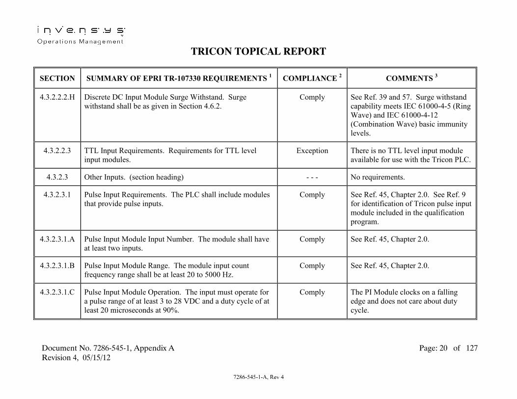
TRICON TOPICAL REPORT
Document No. 7286-545-1, Appendix A Page: 20 of 127 Revision 4, 05/15/12
SECTION SUMMARY OF EPRI TR-107330 REQUIREMENTS 1 COMPLIANCE 2 COMMENTS 3
4.3.2.2.2.H Discrete DC Input Module Surge Withstand. Surge withstand shall be as given in Section 4.6.2.
Comply See Ref. 39 and 57. Surge withstand capability meets IEC 61000-4-5 (Ring Wave) and IEC 61000-4-12 (Combination Wave) basic immunity levels.
4.3.2.2.3 TTL Input Requirements. Requirements for TTL level input modules.
Exception There is no TTL level input module available for use with the Tricon PLC.
4.3.2.3 Other Inputs. (section heading) - - - No requirements.
4.3.2.3.1 Pulse Input Requirements. The PLC shall include modules that provide pulse inputs.
Comply See Ref. 45, Chapter 2.0. See Ref. 9 for identification of Tricon pulse input module included in the qualification program.
4.3.2.3.1.A Pulse Input Module Input Number. The module shall have at least two inputs.
Comply See Ref. 45, Chapter 2.0.
4.3.2.3.1.B Pulse Input Module Range. The module input count frequency range shall be at least 20 to 5000 Hz.
Comply See Ref. 45, Chapter 2.0.
4.3.2.3.1.C Pulse Input Module Operation. The input must operate for a pulse range of at least 3 to 28 VDC and a duty cycle of at least 20 microseconds at 90%.
Comply The PI Module clocks on a falling edge and does not care about duty cycle.

TRICON TOPICAL REPORT
Document No. 7286-545-1, Appendix A Page: 21 of 127 Revision 4, 05/15/12
SECTION SUMMARY OF EPRI TR-107330 REQUIREMENTS 1 COMPLIANCE 2 COMMENTS 3
4.3.2.3.1.D Pulse Input Module Count Accuracy. The module shall have up and down count modes with a range of at least 9999. The accuracy of the count shall be ≤ 0.1%.
Exception See Ref. 45, Chapter 2.0. The Tricon pulse input module provides speed or RPM measurement only.
4.3.2.3.1.E Pulse Input Module Frequency Accuracy. The module shall have a frequency mode with a range of at least 20 to 5000 Hz. The accuracy of the frequency measurement shall be ≤ 0.1%.
Partial Exception See Ref. 45, Chapter 2.0. Accuracy is ± 1.0% of reading from 20 to 99 Hz. Accuracy is ± 0.1% of reading from 100 to 999 Hz. Accuracy is ±0.01% from 1000 to 20,000 Hz
4.3.2.3.1.F Pulse Input Module Response Time. The overall response time of the pulse input module must support the response time requirement given in Section 4.2.1.A.
Comply See Ref. 20, Section 3.0. Pulse Input Modules were not used for Response Time Analyses. Module selection was based on update rates; the selection of digital and analog output modules to include in the test is not significant.
4.3.2.3.1.G Pulse Input Module Group-to-Group Isolation. The group-to-group isolation shall be at least 40 VDC.
N/A See Ref. 45, Chapter 2.0. Tricon pulse input module points are not grouped.
4.3.2.3.1.H
Pulse Input Module Class 1E to Non-1E Isolation. The Class 1E to Non-1E isolation capability shall meet the requirements of Section 4.6.4.
N/A Pulse input modules are not intended for use as a Class 1E to Non-1E isolation device.
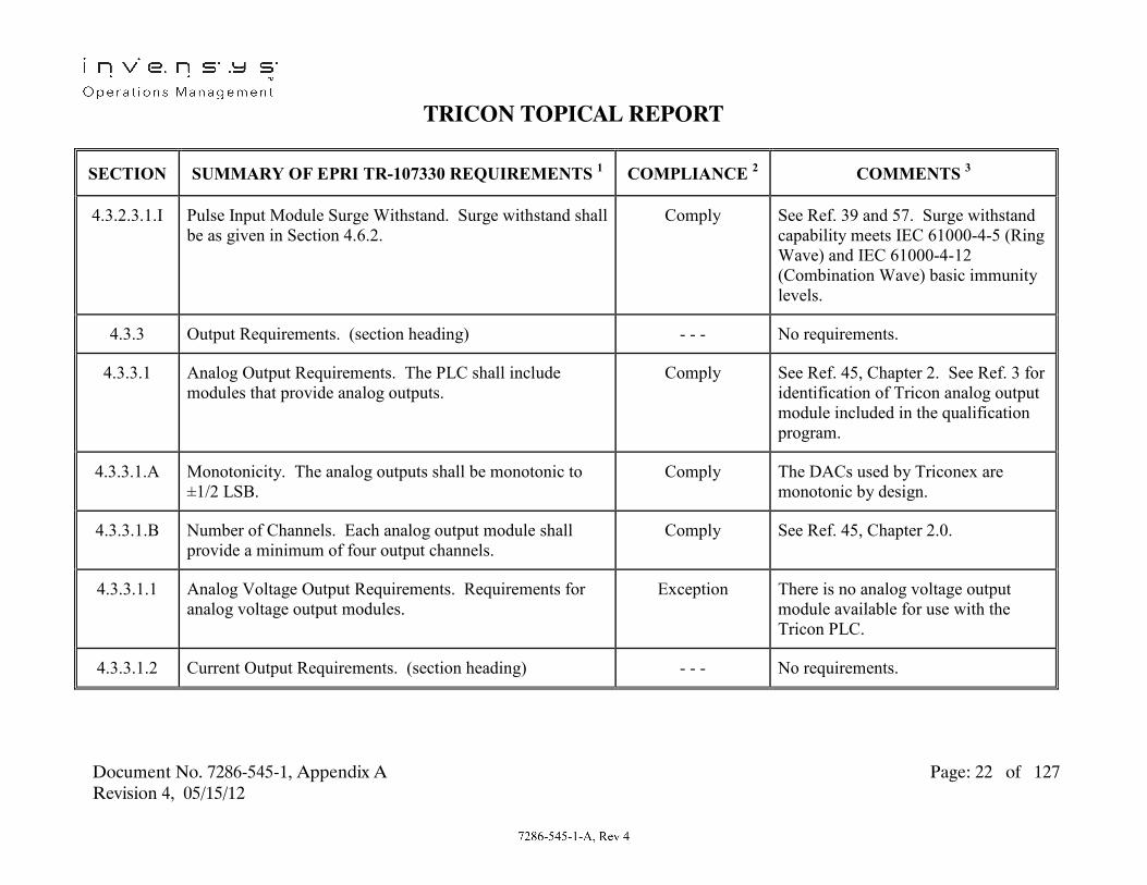
TRICON TOPICAL REPORT
Document No. 7286-545-1, Appendix A Page: 22 of 127 Revision 4, 05/15/12
SECTION SUMMARY OF EPRI TR-107330 REQUIREMENTS 1 COMPLIANCE 2 COMMENTS 3
4.3.2.3.1.I Pulse Input Module Surge Withstand. Surge withstand shall be as given in Section 4.6.2.
Comply See Ref. 39 and 57. Surge withstand capability meets IEC 61000-4-5 (Ring Wave) and IEC 61000-4-12 (Combination Wave) basic immunity levels.
4.3.3 Output Requirements. (section heading) - - - No requirements.
4.3.3.1 Analog Output Requirements. The PLC shall include modules that provide analog outputs.
Comply See Ref. 45, Chapter 2. See Ref. 3 for identification of Tricon analog output module included in the qualification program.
4.3.3.1.A Monotonicity. The analog outputs shall be monotonic to ±1/2 LSB.
Comply The DACs used by Triconex are monotonic by design.
4.3.3.1.B Number of Channels. Each analog output module shall provide a minimum of four output channels.
Comply See Ref. 45, Chapter 2.0.
4.3.3.1.1 Analog Voltage Output Requirements. Requirements for analog voltage output modules.
Exception There is no analog voltage output module available for use with the Tricon PLC.
4.3.3.1.2 Current Output Requirements. (section heading) - - - No requirements.

TRICON TOPICAL REPORT
Document No. 7286-545-1, Appendix A Page: 23 of 127 Revision 4, 05/15/12
SECTION SUMMARY OF EPRI TR-107330 REQUIREMENTS 1 COMPLIANCE 2 COMMENTS 3
4.3.3.1.2.A Analog Current Output Module Ranges. The PLC shall include analog current output modules with ranges of: 4 to 20 mA or 0 to 20 mA, and 10 to 50 mA or 0 to 50 mA.
Partial Exception See Ref. 45, Chapter 2.0. Tricon analog current output module output range is 4 to 20 mA.
4.3.3.1.2.B Analog Current Output Module Accuracy. Overall accuracy shall be ≤ ± 0.32% of full range.
Comply See Ref. 45, Chapter 2.0, and Ref. 9.
4.3.3.1.2.C Analog Current Output Module Resolution. The minimum resolution shall be 12 bits.
Comply See Ref. 45, Chapter 2.0.
4.3.3.1.2.D Analog Current Output Module Load Impedance. The 4 to 20 mA outputs shall support a load impedance of 1 Kohm or less.
Comply See Ref. 45, Chapter 2.0.
4.3.3.1.2.E Analog Current Output Module Response Time. The overall response time of the analog current output modules must support the response time requirement given in Section 4.2.1.A.
Comply Section 4.2.1.A bases response time on AI to DO or DI to DO configurations. Analog outputs are not addressed.
4.3.3.1.2.F Analog Current Output Module Isolation. The group-to-group, module-to-module and module to backplane isolation shall meet the requirements of Section 4.6.4.
N/A Section 4.6.4 provides requirements for Class 1E to Non-1E isolation capability. Tricon analog current output modules are not intended for use as a Class 1E to Non-1E isolation device.

TRICON TOPICAL REPORT
Document No. 7286-545-1, Appendix A Page: 24 of 127 Revision 4, 05/15/12
SECTION SUMMARY OF EPRI TR-107330 REQUIREMENTS 1 COMPLIANCE 2 COMMENTS 3
4.3.3.1.2.G Analog Current Output Module Surge Withstand. Surge withstand shall be as given in Section 4.6.2.
Comply See Ref. 39 and 57. Surge withstand capability meets IEC 61000-4-5 (Ring Wave) and IEC 61000-4-12 (Combination Wave) basic immunity levels.
4.3.3.2 Discrete Output Requirements. The PLC shall include modules that provide discrete outputs.
Comply See Ref. 45, Chapter 2.0. See Ref. 9 for list of Tricon discrete output modules included in the qualification program.
4.3.3.2.A Number of Channels. Each module shall provide a minimum of 8 output channels.
Comply See Ref. 45, Chapter 2.0.
4.3.3.2.B Leakage Current. Leakage current in the OFF state of non-supervised (no internal ringback) modules shall be less than 80% of the minimum current needed to turn ON any digital input module.
Comply See Ref. 45, Section 2.0. Minimum digital input module turn ON current is 3 mA. Maximum non-supervised digital output module leakage current is 2 mA which is < 0.8 x 3 mA.
4.3.3.2.C Output Circuit Interrupter. Outputs must include a circuit interrupter.
Comply See Ref. 48, Chapter 4.
4.3.3.2.D Status Indication. Modules must include indicators that show the ON/OFF status of each point.
Comply See Ref. 45, Chapter 2.0.
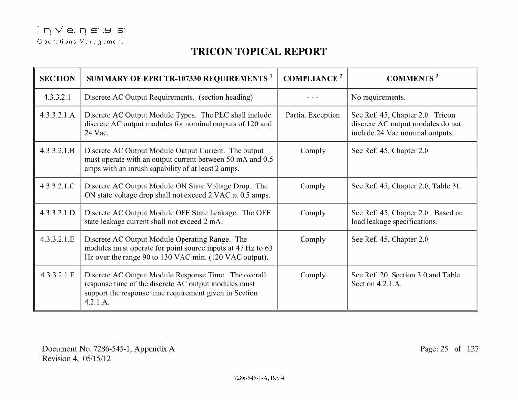
TRICON TOPICAL REPORT
Document No. 7286-545-1, Appendix A Page: 25 of 127 Revision 4, 05/15/12
SECTION SUMMARY OF EPRI TR-107330 REQUIREMENTS 1 COMPLIANCE 2 COMMENTS 3
4.3.3.2.1 Discrete AC Output Requirements. (section heading) - - - No requirements.
4.3.3.2.1.A Discrete AC Output Module Types. The PLC shall include discrete AC output modules for nominal outputs of 120 and 24 Vac.
Partial Exception See Ref. 45, Chapter 2.0. Tricon discrete AC output modules do not include 24 Vac nominal outputs.
4.3.3.2.1.B Discrete AC Output Module Output Current. The output must operate with an output current between 50 mA and 0.5 amps with an inrush capability of at least 2 amps.
Comply See Ref. 45, Chapter 2.0
4.3.3.2.1.C Discrete AC Output Module ON State Voltage Drop. The ON state voltage drop shall not exceed 2 VAC at 0.5 amps.
Comply See Ref. 45, Chapter 2.0, Table 31.
4.3.3.2.1.D Discrete AC Output Module OFF State Leakage. The OFF state leakage current shall not exceed 2 mA.
Comply See Ref. 45, Chapter 2.0. Based on load leakage specifications.
4.3.3.2.1.E Discrete AC Output Module Operating Range. The modules must operate for point source inputs at 47 Hz to 63 Hz over the range 90 to 130 VAC min. (120 VAC output).
Comply See Ref. 45, Chapter 2.0
4.3.3.2.1.F Discrete AC Output Module Response Time. The overall response time of the discrete AC output modules must support the response time requirement given in Section 4.2.1.A.
Comply See Ref. 20, Section 3.0 and Table Section 4.2.1.A.

TRICON TOPICAL REPORT
Document No. 7286-545-1, Appendix A Page: 26 of 127 Revision 4, 05/15/12
SECTION SUMMARY OF EPRI TR-107330 REQUIREMENTS 1 COMPLIANCE 2 COMMENTS 3
4.3.3.2.1.G Discrete AC Output Module Group-to-Group Isolation. The group-to-group isolation shall be at least 600 volts peak for 120 VAC outputs.
N/A See Ref. 45, Chapter 2.0. Tricon discrete AC output module points are not grouped.
4.3.3.2.1.H Discrete AC Output Module Class 1E to Non-1E Isolation. The Class 1E to Non-1E isolation capability shall meet the requirements of Section 4.6.4.
N/A Discrete AC output modules are not intended for use as a Class 1E to Non-1E isolation device.
4.3.3.2.1.I Discrete AC Output Module Surge Withstand. Surge withstand shall be as given in Section 4.6.2.
Comply See Ref. 39 and 57. Surge withstand capability meets IEC 61000-4-5 (Ring Wave) and IEC 61000-4-12 (Combination Wave) basic immunity levels.
4.3.3.2.2 Discrete DC Output Requirements. (section heading) - - - No requirements.
4.3.3.2.2.A Discrete DC Output Module Types. The PLC shall include discrete DC output modules for nominal outputs of 125, 48, 24, 15 and 12 Vdc.
Partial Exception See Ref. 45, Chapter 2.0. Tricon discrete DC output modules include 120, 48 and 24 Vdc nominal outputs.
4.3.3.2.2.B Discrete DC Output Module Output Current. The outputs must operate with an output current between 50 mA and 0.5 amps with an inrush capability of at least 2 amps.
Comply See Ref. 45, Chapter 2.0.

TRICON TOPICAL REPORT
Document No. 7286-545-1, Appendix A Page: 27 of 127 Revision 4, 05/15/12
SECTION SUMMARY OF EPRI TR-107330 REQUIREMENTS 1 COMPLIANCE 2 COMMENTS 3
4.3.3.2.2.C Discrete DC Output Module ON State Voltage Drop. The ON state voltage drop shall not exceed 2 Vdc at 0.5 amps.
Exception See Ref. 45, Chapter 2.0. Module Model 3607E ON state voltage drop is < 3 V.
4.3.3.2.2.D Discrete DC Output Module OFF State Leakage. The OFF state leakage current shall not exceed 2 mA.
Exception See Ref. 45, Chapter 2.0. Module Models 3625 OFF state load leakage is 4 mA maximum.
4.3.3.2.2.E Discrete DC Output Module Operating Range. The module points must operate for source inputs of 90 to 140 Vdc min. (125 Vdc output), 35 to 60 VDC min. (48 Vdc output), and 20 to 28 Vdc min. (24 Vdc output).
Exception See Ref. 45, Section 2.0. Module Model 3607E (48 Vdc output) operates from 44 to 80 Vdc. Module Model 3625 (24 Vdc output) operates from 22 to 45 Vdc.
4.3.3.2.2.F Discrete DC Output Module Response Time. The overall response time of the discrete DC output modules must support the response time requirement given in Section 4.2.1.A.
Comply See Ref. 20, Section 3.0 and Table Section 4.2.1.A.
4.3.3.2.2.G
Discrete DC Output Module Group-to-Group Isolation. The group-to-group isolation shall be at least twice nominal output.
N/A See Ref. 45, Chapter 2.0. Tricon discrete DC output module points are not grouped.

TRICON TOPICAL REPORT
Document No. 7286-545-1, Appendix A Page: 28 of 127 Revision 4, 05/15/12
SECTION SUMMARY OF EPRI TR-107330 REQUIREMENTS 1 COMPLIANCE 2 COMMENTS 3
4.3.3.2.2.H Discrete DC Output Module Class 1E to Non-1E Isolation. The Class 1E to Non-1E isolation capability shall meet the requirements of Section 4.6.4.
N/A Discrete DC output modules are not intended for use as a Class 1E to Non-1E isolation device.
4.3.3.2.2.I Discrete DC Output Module Surge Withstand. Surge withstand shall be as given in Section 4.6.2.
Comply See Ref. 39 and 57. Surge withstand capability meets IEC 61000-4-5 (Ring Wave) and IEC 61000-4-12 (Combination Wave) basic immunity levels.
4.3.3.2.3 Relay Output Requirements. (section heading) - - - No requirements.
4.3.3.2.3.A Relay Output Module Types. The PLC shall include relay output modules that provide normally open and normally closed contacts.
Partial Exception See Ref. 45, Chapter 2.0. Tricon relay output module contacts are normally open.
4.3.3.2.3.B Relay Output Module Output Current. The continuous current carrying capacity must be at least 2 amps with make and break switching capability of at least 750 VA for AC and 150 watts for DC.
Comply See Ref. 45, Chapter 2.0
4.3.3.2.3.C Relay Output Module Contact Resistance. The contact resistance shall not exceed 2 ohms.
Comply Per the vendor published catalog information, the contacts have a maximum resistance of 30 milli-ohms.

TRICON TOPICAL REPORT
Document No. 7286-545-1, Appendix A Page: 29 of 127 Revision 4, 05/15/12
SECTION SUMMARY OF EPRI TR-107330 REQUIREMENTS 1 COMPLIANCE 2 COMMENTS 3
4.3.3.2.3.D Relay Module Operating Range. The contacts must operate from a source of up to 30 VDC or 150 VAC.
Comply See Ref. 45, Chapter 2.0
4.3.3.2.3.E Relay Output Module Response Time. The overall response time of the relay output module must support the response time requirement given in Section 4.2.1.A.
Comply See Ref. 20, Section 3.0 and Table Section 4.2.1.A.
4.3.3.2.3.F Relay Output Module Group-to-Group Isolation. The group-to-group isolation shall be at least 600 volts peak.
N/A See Ref. 45, Section 2. Tricon relay output module points are not grouped.
4.3.3.2.3.G Relay Output Module Class 1E to Non-1E Isolation. The Class 1E to Non-1E isolation capability shall meet the requirements of Section 4.6.4.
Comply See Ref. 41. Isolation test voltage levels selected per IEEE-384, Section 7.2.2.1.
4.3.3.2.3.H Relay Output Module Surge Withstand. Surge withstand shall be as given in Section 4.6.2.
Comply See Ref. 39 and 57 and 57. Surge withstand capability meets IEC 61000-4-5 (Ring Wave) and IEC 61000-4-12 (Combination Wave) basic immunity levels.
4.3.3.2.4 TTL Output Requirements. Requirements for TTL level output modules.
Exception There is no TTL level output module available for use with the Tricon PLC.
4.3.4 Processor/Other System Component Requirements. (section heading)
- - - No requirements.

TRICON TOPICAL REPORT
Document No. 7286-545-1, Appendix A Page: 30 of 127 Revision 4, 05/15/12
SECTION SUMMARY OF EPRI TR-107330 REQUIREMENTS 1 COMPLIANCE 2 COMMENTS 3
4.3.4.1 Processor Loop Time Requirements. Processor loop time shall support the response time requirement given in Section 4.2.1.A. Also, processor loop time shall be faster than the longer of the analog input conversion time or the period associated with 2.5 times the analog filter cutoff frequency.
Comply See Ref. 20, Section 3.0 and Reference 52, Section 4. The processor loop time is included in the overall application program scan time, which is set by the user. For each nuclear plant application, the actual set scan time must be evaluated and demonstrated acceptable based on the data acquisition rates and response time requirements of the plant application.

TRICON TOPICAL REPORT
Document No. 7286-545-1, Appendix A Page: 31 of 127 Revision 4, 05/15/12
SECTION SUMMARY OF EPRI TR-107330 REQUIREMENTS 1 COMPLIANCE 2 COMMENTS 3
4.3.4.2 Memory Capacity and Data Retention Capability Requirements. The memory capacity of the main processor shall provide sufficient memory to execute a single application program with the number of program elements given. The memory used to contain the program shall be capable of retaining the information for a minimum of 6 months with no power applied. Any memory used for field modifiable constants shall be capable of at least 100,000 write cycles.
Comply
Comply
Comply
See Ref. 45. A four chassis, 24 module Tricon system programmed as described in TR Section 4.3.4.2 has over 90% remaining free memory. See Ref. 46 for number of supported program elements. See Ref. 45, Chapter 2, Page 28. Memory used for field modified constants is battery backed up ram on the 3008 main processors. There is no limit on the number of write cycles on this memory.
4.3.4.3 Data Acquisition Requirements. The PLC shall be capable of transferring information between the main processor and I/O modules mounted in the same or expansion chassis. The data transfer rate shall support the response time requirement given in Section 4.2.1.A, and 4.3.4.1.
Comply See Ref. 45, Chapter 2, page 38-41.See Ref. 7, Section 4.0 and Table Section 4.2.1.A.

TRICON TOPICAL REPORT
Document No. 7286-545-1, Appendix A Page: 32 of 127 Revision 4, 05/15/12
SECTION SUMMARY OF EPRI TR-107330 REQUIREMENTS 1 COMPLIANCE 2 COMMENTS 3
4.3.4.3.A Main Chassis Interconnect Device Operation. Devices used to interface remote or expansion chassis to the main chassis shall meet the range of environmental conditions given in Section 4.3.6. Failures of the chassis interconnect devices shall not defeat the ability to transfer data on the main chassis.
Comply
Comply
See Ref. 35. Remote and expansion chassis interface devices were included in environmental testing. See Ref. 20, Section 7. Fault simulations of interconnect hardware performed during Operability tests showed that main chassis data transfer is not interrupted.
4.3.4.3.B Main Chassis Interconnect Device Failure. Failures of the chassis interconnect devices shall not affect memory capacity or main processor data retention.
Comply This attribute is inherent in the design of the Tricon. Local & Remote I/O operate independent of the MP memory.
4.3.4.3.C Main Chassis Interconnect Device Loss of Power. Loss of power to chassis interconnect devices shall not defeat the ability to transfer data on the main chassis or I/O on any other chassis.
Comply See Ref. 20, Section 7. Fault simulation of chassis power supplies performed during Operability tests showed that main chassis data transfer is not interrupted to local I/O or any other chassis.

TRICON TOPICAL REPORT
Document No. 7286-545-1, Appendix A Page: 33 of 127 Revision 4, 05/15/12
SECTION SUMMARY OF EPRI TR-107330 REQUIREMENTS 1 COMPLIANCE 2 COMMENTS 3
4.3.4.3.D Main Chassis Interconnect Device Class 1E to Non-1E Isolation. The Class 1E to Non-1E isolation capability shall meet the requirements of Section 4.6.4.
N/A See Ref. 41, Section 3. Multi-pin cable connectors in-between Tricon Chassis are not intended for use as a Class 1E to Non-1E isolation device. Fiber optic cable and interface (RXM) module connectors inherently provide Class 1E to Non-1E isolation through non-conducting fiber optic cables.
4.3.4.3.E Main Chassis Interconnect Device Surge Withstand. Surge withstand shall be as given in Section 4.6.2.
N/A See Ref. 27, Section 3.2. No interposing devices are used on multi-pin cable connectors and therefore surge testing is not required. Fiber optic cable and interface (RXM) module connectors inherently provide surge protection through non-conducting fiber optic cables.
4.3.4.3.F Main Chassis Interconnect Device Data Acquisition Time. Data acquisition time shall be deterministic or manufacturer shall provide information to establish timing effect.
Comply See Ref. 45, Chapter 2, Page 31 and 44. All expansion or remote chassis communication is at same rate as main chassis communication.
4.3.4.3.G Redundant Inter-Processor Data Acquisition Backplane Busses. Descriptive information.
- - - No requirements.

TRICON TOPICAL REPORT
Document No. 7286-545-1, Appendix A Page: 34 of 127 Revision 4, 05/15/12
SECTION SUMMARY OF EPRI TR-107330 REQUIREMENTS 1 COMPLIANCE 2 COMMENTS 3
4.3.4.3.G.1 Redundant Inter-Processor Data Acquisition Backplane Busses. Busses shall be at least dual redundant.
Comply See Ref. 42.
4.3.4.3.G.2 Redundant Inter-Processor Data Acquisition Backplane Busses. Loss of one bus shall not cause misoperation.
Comply See Ref. 42.
4.3.4.3.G.3 Redundant Inter-Processor Data Acquisition Backplane Busses. Loss of all busses shall not result in an indeterminate operation.
Comply See Ref. 42.
4.3.4.3.G.4 Redundant Inter-Processor Data Acquisition Backplane Busses. External alarm shall be activated on loss of one bus.
Comply See Ref. 42.
4.3.4.3.G.5 Redundant Inter-Processor Data Acquisition Backplane Busses. Data acquisition time shall be deterministic.
Comply See Ref. 42.
4.3.4.3.G.6 Redundant Inter-Processor Data Acquisition Backplane Busses. Operation of busses shall support the response time requirement given in Section 4.2.1.A.
Comply See Ref. 20, Section 3.0. Redundant busses are always operational. Therefore, response time determination and qualification testing was performed with redundant busses operational.

TRICON TOPICAL REPORT
Document No. 7286-545-1, Appendix A Page: 35 of 127 Revision 4, 05/15/12
SECTION SUMMARY OF EPRI TR-107330 REQUIREMENTS 1 COMPLIANCE 2 COMMENTS 3
4.3.4.4 Communication Port Requirements. The main processor shall provide at least one communication port.
Comply See Ref. 45, Chapter 2, Page 148. TCM Module.
4.3.4.4.A Communication Port Data Rate. The port shall support data rates up to 9600 baud.
Comply See Ref. 45, Table 60
4.3.4.4.B Communication Port Interface. The port shall support RS-232, RS-422, RS-485 or other widely used protocol.
Comply See Ref. 45, Table 61.
4.3.4.4.C Communication Port Connector. The port shall provide positive hold down of connectors.
Comply See Ref. 50, Appendix A. Standard DB-9 connectors provided on TCM ports.
4.3.4.4.D
Communication Port Isolation. For multiple ports, the port-to-port isolation shall be at least 300 volts peak.
Comply See Ref. 50, Appendix A
4.3.4.4.E Communication Port Class 1E to Non-1E Isolation. The Class 1E to Non-1E isolation capability shall meet the requirements of Section 4.6.4.
Exception See Ref. 41, Section 7.0. Tricon TCM serial communication ports tested for Class 1E to Non-1E isolation capability at 250 Vac (vs. 600 Vac required by TR) and 250 Vdc. Test level is based on maximum credible voltage (see Ref. 41).

TRICON TOPICAL REPORT
Document No. 7286-545-1, Appendix A Page: 36 of 127 Revision 4, 05/15/12
SECTION SUMMARY OF EPRI TR-107330 REQUIREMENTS 1 COMPLIANCE 2 COMMENTS 3
4.3.4.4.F Communication Port Surge Withstand. Surge withstand shall be as given in Section 4.6.2.
Comply See Ref. 39 and 57. Surge withstand capability meets IEC 61000-4-5 (Ring Wave) and IEC 61000-4-12 (Combination Wave) basic immunity levels.
4.3.4.5
Coprocessor Module Requirements. Detailed requirements for coprocessors that may be installed in I/O slots but contain local processing capability independent of the main processor.
N/A See Ref. 20. Section 3.0. Operation of Tricon coprocessors is invoked automatically during application program execution. Coprocessor performance is evaluated during all qualification tests.
4.3.4.6 Chassis Requirements. Chassis must be suitable for mounting in a standard 19 inch rack, and must have adequate strength and provide positive hold down of modules sufficient to meet seismic withstand requirements.
Comply See Ref. 45, Chapter 3, Page 169. See Ref. 13, Drawing No. 9600164-102 for seismic mounting details. See Ref. 36, Section 7.0 for summary of seismic test results.
4.3.4.7
Backup Devices/Redundancy Requirements. Descriptive information.
- - - No requirements.

TRICON TOPICAL REPORT
Document No. 7286-545-1, Appendix A Page: 37 of 127 Revision 4, 05/15/12
SECTION SUMMARY OF EPRI TR-107330 REQUIREMENTS 1 COMPLIANCE 2 COMMENTS 3
4.3.4.7.A Redundant Device Requirements. Transfer to a redundant device shall occur within the larger of the main processor scan cycle or three data conversion cycles of the failed module.
N/A See Ref. 20, Section 7, Subsection 1.0. Because redundant components are always online, component faults do not result in transfers to a redundant component.
4.3.4.7.B Redundant Device Requirements. Undetected failures in redundant components shall be detectable during periodic surveillance.
N/A See Ref. 20, Section 7, Subsection 1.0. Because redundant components are always online, failures can be immediately indicated through redundant alarm circuits.
4.3.4.7.C Redundant Device Requirements. Diagnostics shall not result in indeterminate failure states and repetitive switching between redundant components.
N/A See Ref. 20, Section 7, Subsection 1.0. Because redundant components are always online, switching between failed components does not occur.
4.3.4.7.D Redundant Device Requirements. Requirements for affect of transfer mechanism operation on input/output module operation.
N/A See Ref. 20, Section 7, Subsection 4.0. Because redundant components are always online, “transfers” to redundant components are bumpless.
4.3.5 Programming Terminal Requirements. Special programming terminal hardware or software shall meet the requirements of Sections 4.4.4, 7.7.2 and 7.5.2.
Comply See Table Sections 4.4.4, 7.7.2, and 7.5.2. No special programming terminal hardware is required.

TRICON TOPICAL REPORT
Document No. 7286-545-1, Appendix A Page: 38 of 127 Revision 4, 05/15/12
SECTION SUMMARY OF EPRI TR-107330 REQUIREMENTS 1 COMPLIANCE 2 COMMENTS 3
4.3.6 Environmental Requirements. (section heading) - - - No requirements.
4.3.6.1
Normal Environmental Basic Requirements. The normal PLC operating environment is: Temperature Range: 16 to 40ºC (60 to 104ºF). Humidity Range: 40 to 95% (non-condensing) Power Source Range: As given in Section 4.6.1.1 Radiation Exposure: Up to 1000 Rads
Comply
Exception
Comply
See Ref. 49. Tricon is rated for 0 to 60ºC (32 to 140ºF), 5% to 95% humidity (non-condensing). See Table Section 4.6.1.1 for exceptions to power source range. See Ref. 34. Tricon has been tested to a 1000 Rad dose of Co60 gamma radiation.
4.3.6.2 Abnormal Environmental Basic Requirements. The abnormal PLC operating environment is: Temperature Range: 4 to 50ºC (40 to 120ºF). Humidity Range: 10 to 95% (non-condensing) Power Source Range: As given in Section 4.6.1.1 Radiation Exposure: Up to 1000 Rads
Comply
Exception
Comply
See Ref. 49. Tricon is rated for 0 to 60ºC (32 to 140ºF), 5% to 95% humidity (non-condensing). See Table Section 4.6.1.1 for exceptions to power source range. See Ref. 34. Tricon has been tested to a 1000 Rad dose of Co60 gamma radiation.

TRICON TOPICAL REPORT
Document No. 7286-545-1, Appendix A Page: 39 of 127 Revision 4, 05/15/12
SECTION SUMMARY OF EPRI TR-107330 REQUIREMENTS 1 COMPLIANCE 2 COMMENTS 3
4.3.6.3 Environmental Withstand Specific Requirements. PLC shall operate for the temperature/humidity profile given in TR Figure 4-4 with operability as given in Section 5.3. Evaluations may be used to establish radiation withstand capability.
Comply See Ref. 35, Section 7.0 & Ref. 34 for tested radiation capability.
4.3.7
EMI/RFI Withstand Requirements. The PLC shall withstand EMI/RFI levels given in EPRI TR-102323. When exposed to the radiated and conducted test levels, the PLC processors shall continue to function, I/O data transfer shall not be interrupted, discrete I/O shall not change state, analog I/O shall not vary more than 3%.
Exception Tricon showed some susceptibilities to NRC RG 1.1.80 Rev. 1 (CE101). See Ref. 37 for results.
4.3.8
Electrostatic Discharge (ESD) Withstand Requirements. The PLC shall withstand ESD levels given in EPRI TR-102323.
Comply See Ref. 40.

TRICON TOPICAL REPORT
Document No. 7286-545-1, Appendix A Page: 40 of 127 Revision 4, 05/15/12
SECTION SUMMARY OF EPRI TR-107330 REQUIREMENTS 1 COMPLIANCE 2 COMMENTS 3
4.3.9 Seismic Withstand Requirements. PLC shall be suitable for qualification as a Category 1 Seismic device. The PLC shall meet performance requirements during and after exposure to OBE and SSE levels shown in TR Figure 4-5.Relay contacts of relay output modules shall not chatter.
Comply See Ref. 36. Seismic testing demonstrates that the TRICON is qualified as a Category I seismic device within the test limits shown in Figure 4-5. Due to limitations of the seismic test table, the five OBE tests and the SSE test of the TRICON were performed using a test response spectrum (TRS) that did not envelope the required response spectrum (RRS) below 4.5 Hz for the OBE and 6.3 Hz for the SSE
4.4 Software/Firmware. (section heading) - - - No requirements.
4.4.1 Executive. (section heading) - - - No requirements.
4.4.1.1
Background. Descriptive information. - - - No requirements.

TRICON TOPICAL REPORT
Document No. 7286-545-1, Appendix A Page: 41 of 127 Revision 4, 05/15/12
SECTION SUMMARY OF EPRI TR-107330 REQUIREMENTS 1 COMPLIANCE 2 COMMENTS 3
4.4.1.2
Main Processor Executive Capability Requirements. The main processor executive shall: A. Acquire inputs from the modules. B. Implement the application program in a continuous loop. C. Load outputs to the modules. D. Perform power-up and run time diagnostics. E. Manage communications. F. Upload application programs. G. Support on-line diagnostics, maint. and troubleshooting. H. Implement the application program functions. I. Perform power-up initialize functions. J. Implement redundancy functions.
Comply See Ref. 42.

TRICON TOPICAL REPORT
Document No. 7286-545-1, Appendix A Page: 42 of 127 Revision 4, 05/15/12
SECTION SUMMARY OF EPRI TR-107330 REQUIREMENTS 1 COMPLIANCE 2 COMMENTS 3
4.4.1.3 Program Flow Control Requirements. Requirements for PLCs where scanning of the inputs and application program execution are performed in parallel. The use of application program interrupts shall be restricted. The use of interrupts that result in non-deterministic application program execution should not be permitted. Requirements for PLCs that implement interrupts that could result in non-deterministic application program execution.
Comply
Comply
N/A
See Ref. 42. Tricon is a scan based system execution of each application program scan is preceded by an input module data request. While program is being executed for a given scan, the input modules continue to collect inputs from the field devices for the next scan. See above. Tricon is a scanned based system. See Ref. 42
4.4.1.4 Unintended/Unused Function Isolation Requirements. Descriptive information.
- - - No requirements.
4.4.1.5 Coprocessor Executive Capability. (section heading) - - - No requirements.
4.4.1.5.1 Coprocessor Executive Capability Background. Descriptive information.
- - - No requirements.
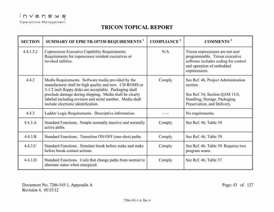
TRICON TOPICAL REPORT
Document No. 7286-545-1, Appendix A Page: 43 of 127 Revision 4, 05/15/12
SECTION SUMMARY OF EPRI TR-107330 REQUIREMENTS 1 COMPLIANCE 2 COMMENTS 3
4.4.1.5.2 Coprocessor Executive Capability Requirements. Requirements for coprocessor resident executives or invoked utilities.
N/A Tricon coprocessors are not user programmable. Tricon executive software includes coding for control and operation of embedded coprocessors.
4.4.2 Media Requirements. Software media provided by the manufacturer shall be high quality and new. CD-ROMS or 3-1/2 inch floppy disks are acceptable. Packaging shall preclude damage during shipping. Media shall be clearly labeled including revision and serial number. Media shall include electronic identification.
Comply See Ref. 46, Project Administration section. See Ref. 54, Section QAM 15.0, Handling, Storage, Packaging Preservation, and Delivery.
4.4.3 Ladder Logic Requirements. Descriptive information. - - - No requirements.
4.4.3.A Standard Functions. Simple normally inactive and normally active paths.
Comply See Ref. 46, Table 39.
4.4.3.B Standard Functions. Transition ON/OFF (one-shot) paths. Comply See Ref. 46, Table 39.
4.4.3.C Standard Functions. Simulate break before make and make before break contact actions.
Comply See Ref. 46, Table 39. Requires two program scans.
4.4.3.D Standard Functions. Coils that change paths from normal to alternate states when energized.
Comply See Ref. 46, Table 37.

TRICON TOPICAL REPORT
Document No. 7286-545-1, Appendix A Page: 44 of 127 Revision 4, 05/15/12
SECTION SUMMARY OF EPRI TR-107330 REQUIREMENTS 1 COMPLIANCE 2 COMMENTS 3
4.4.3.E Standard Functions. Coils that change paths from normal to alternate states when energized and remain there until the coils are de-energized and a reset signal is applied.
Comply See Ref. 46, Table 37.
4.4.3.F Standard Functions. Timing functions that can be set from 0.1 seconds to 2 hours.
Comply See Ref. 47, TMR function. Must be set to multiples of the application program scan time.
4.4.3.G Standard Functions. Counters that perform up or down counting from at least 1 to 9999.
Comply See Ref. 47, CTD and CTU functions.
4.4.3.H Standard Functions. Methods to perform less than, equal to and greater than numeric comparisons.
Comply See Ref. 47, LT, GT and EQ conditional statements.
4.4.3.I Standard Functions. Addition, subtraction, multiplication, and division functions for integer and floating point numbers. Out of range and error on division by zero.
Comply See Ref. 47, ADD, SUB, MUL and DIV operators, DINT and REAL point types. CHK_ERR function block.
4.4.3.J Standard Functions. Square root, exponentiation and logarithm functions. Out of range indications.
Comply See Ref. 47, SQRT, EXPT and LOG functions. CHK_ERR function block.

TRICON TOPICAL REPORT
Document No. 7286-545-1, Appendix A Page: 45 of 127 Revision 4, 05/15/12
SECTION SUMMARY OF EPRI TR-107330 REQUIREMENTS 1 COMPLIANCE 2 COMMENTS 3
4.4.3.K Standard Functions. A PID algorithm with 5 to 500% proportional band, 1% resolution, 0 to 100 repeats per minute integral action, 1 repeat per second resolution, anti-reset windup, 0 to 100 minutes rate action, 1 second resolution, output limiting, out of range indication, bumpless transfer to external switch activated manual control, cascade control.
Comply See Ref. 47, PID and CHK_ERR function blocks. See Ref. 15.
4.4.3.L Standard Functions. A dynamic compensation function. Lead/lag ratio of 0 to 10, minimum resolution of 0.05, 0.01 to 100 minute lag time, minimum 1 second resolution, lead action filter.
Comply See Ref. 47, LEADLAG and EXPFLTR function blocks. See Ref. 15.
4.4.3.M Standard Functions. Capability to put limits on values. Comply See Ref. 47, LIMIT function.
4.4.3.N Standard Functions. Implement a function generator with at least five slopes.
Comply See Ref. 15.
4.4.3.O Standard Functions. Support Section 4.9.1 communications requirements.
Comply See Table Section 4.9.1.
4.4.3.P Standard Functions. Functions to capture results of self-tests.
Comply See Ref. 47.
4.4.3.Q Standard Functions. Functions to implement sequence of events requirements in Section 4.4.9.
Comply See Ref. 59.

TRICON TOPICAL REPORT
Document No. 7286-545-1, Appendix A Page: 46 of 127 Revision 4, 05/15/12
SECTION SUMMARY OF EPRI TR-107330 REQUIREMENTS 1 COMPLIANCE 2 COMMENTS 3
4.4.3.R Standard Functions. AND, OR and XOR bit manipulation functions.
Comply See 47, AND, OR and XOR library functions.
4.4.3.S Standard Functions. Functions to store results in buffer type memory, 10 instances of 50 values. Facilities to transmit this data over a serial port.
Comply See Ref. 15.
4.4.3.T Standard Functions. Functions to implement requirements of Section 4.4.7.2.
Comply See Table Section 4.4.7.2.
4.4.3.U Standard Functions. Capability to attach comments to ladder logic rungs.
Comply See Ref. 47.
4.4.4
Software Tools Requirements. A tool shall be provided for programming, debugging and documentation.
Comply See Ref. 46 and 47. The tool is Tristation 1131.
4.4.4.A Software Tools Requirements. Ability to use a host device to enter a program in the PLC.
Comply See Ref. 46, Introduction.
4.4.4.A.1 Software Tools Requirements. Ability to attach explanatory comments to program steps.
Comply See Ref. 47.
4.4.4.A.2 Software Tools Requirements. Ability to store programs on removable magnetic media.
Comply See Ref. 46 and 47Appendix A.

TRICON TOPICAL REPORT
Document No. 7286-545-1, Appendix A Page: 47 of 127 Revision 4, 05/15/12
SECTION SUMMARY OF EPRI TR-107330 REQUIREMENTS 1 COMPLIANCE 2 COMMENTS 3
4.4.4.A.3 Software Tools Requirements. Ability to perform bit by bit comparison of program contained in PLC and program contained in programming device.
Comply See Ref. 46Appendix A.
4.4.4.A.4 Software Tools Requirements. Ability to print the program contained in the PLC or programming device in a fashion similar in appearance to programming device display. Include supplemental prints of programming values.
Comply See Ref. 46 and 47, .
4.4.4.A.5 Software Tools Requirements. Features to aid in I/O mapping and memory management of the PLC.
Comply See Ref. 47 and 49
4.4.4.A.6 Software Tools Requirements. System security requirements similar to Section 4.9.2.
Comply See Table Section 4.9.2.
4.4.4.B Debugging Aids. Descriptive information. - - - No requirements.
4.4.4.B.1 Debugging Aids. Ability to highlight all discrete elements not in their normal state.
Comply See Ref. 46.
4.4.4.B.2 Debugging Aids. Ability to display input, output and intermediate program values.
Comply See Ref. 46.
4.4.4.B.3 Debugging Aids. Ability to set constants and variables to arbitrary values, including values outside normal range.
Comply See Ref. 46.

TRICON TOPICAL REPORT
Document No. 7286-545-1, Appendix A Page: 48 of 127 Revision 4, 05/15/12
SECTION SUMMARY OF EPRI TR-107330 REQUIREMENTS 1 COMPLIANCE 2 COMMENTS 3
4.4.4.B.4 Debugging Aids. Ability to force outputs. Comply See Ref. 46.
4.4.4.B.5 Debugging Aids. Ability to single step through a program. Comply See Ref. 46.
4.4.4.B.6 Debugging Aids. Ability to view the status of memory where error codes and other status information is stored.
Comply See Ref. 60.
4.4.4.C Software Tools Requirements. Apply Configuration management requirements per Section 7.7.3.
Comply See Table Section 7.7.3.
4.4.4.D Software Tools Requirements. Meet requirements of Sections 4.4.5.2 and 4.4.7.2.
Comply See Table Sections 4.4.5.2 and 4.4.7.2.
4.4.4.E Software Tools Requirements. Software Verification and Validation requirements of Section 7.4 shall be applied to the software tools.
Comply See Ref. 52.
4.4.4.F Software Tools Requirements. Provide features to aid in detecting faults in redundant components which are not detectable by self-diagnostics.
N/A All faults in redundant components are detectable through self-diagnostics.
4.4.5 Configuration Identification. (section heading) - - - No requirements.
4.4.5.1 Configuration Identification Background. Descriptive information.
- - - No requirements.

TRICON TOPICAL REPORT
Document No. 7286-545-1, Appendix A Page: 49 of 127 Revision 4, 05/15/12
SECTION SUMMARY OF EPRI TR-107330 REQUIREMENTS 1 COMPLIANCE 2 COMMENTS 3
4.4.5.2 Configuration Management Aids Requirements. Descriptive information.
- - - No requirements.
4.4.5.2.A Configuration Management. The PLC executive shall include a retrievable, embedded electronic revision level.
Comply See Ref. 60.
4.4.5.2.B Configuration Management. Configuration information of configurable modules shall be retrievable in the field.
Comply See Ref. 47.
4.4.5.2.C Configuration Management. Software tools for modifying device configurations shall provide measures to prevent unauthorized access.
Comply See Ref. 47.
4.4.5.2.D Configuration Management. PLC and support tools shall provide capability to extract and record database information, including program constants.
Comply See Ref. 47.
4.4.5.2.E Configuration Management. All PLC devices that include firmware shall be marked with an identifier that includes revision level.
Comply See Ref. 45, Appendix A.
4.4.5.2.F Configuration Management. For PLCs with redundancy, tools shall provide capability to confirm that configurations are consistent.
Comply See items 4.4.5.2.A and 4.4.5.2.B above.

TRICON TOPICAL REPORT
Document No. 7286-545-1, Appendix A Page: 50 of 127 Revision 4, 05/15/12
SECTION SUMMARY OF EPRI TR-107330 REQUIREMENTS 1 COMPLIANCE 2 COMMENTS 3
4.4.6 Diagnostics Requirements. (section heading) - - - No requirements.
4.4.6.1 General Diagnostic Requirements. PLC must have sufficient diagnostics and test capability to detect all failures that could prevent the PLC from performing its intended safety function. Items 4.4.6.1.1 through 4.4.6.1.6 must be covered by on-line self test. Items 4.4.6.1.7 and 4.4.6.1.8 must be covered in power-up tests. Short term diagnostics changes in module outputs shall be 2 msec or less for DC outputs and 1/2 cycle or less for AC outputs. Capability to disable these diagnostics shall be provided.
Comply
Comply
Comply
Comply
See Table Sections 4.4.6.1.1 through 4.4.6.1.14. See Table Section 4.4.6.2. See Table Section 4.4.6.3. See Ref. 45, Chapter 2 Page 83.

TRICON TOPICAL REPORT
Document No. 7286-545-1, Appendix A Page: 51 of 127 Revision 4, 05/15/12
SECTION SUMMARY OF EPRI TR-107330 REQUIREMENTS 1 COMPLIANCE 2 COMMENTS 3
4.4.6.1.1 Processor Stall. For PLCs with redundant processors, the PLC shall detect processor stall and halt operation of the failed processor.
Comply Failure Detect: See Ref. 42, Section 8.13. Failure Alarm: See Ref. 45, Tables 74 and 75, MP Active LED. Application Program Interface: See Ref. 47, TR-MP-STATUS function.
4.4.6.1.2
Executive Program Error. Check of executive firmware integrity using a checksum or similar test.
Comply Failure Detect: See Ref. 42, Section 8.13. Failure Alarm: See Ref. 45, Chapter 4, Table 75, MP Fault LED. Application Program Interface: See Ref. 47, TR-MP-STATUS function.

TRICON TOPICAL REPORT
Document No. 7286-545-1, Appendix A Page: 52 of 127 Revision 4, 05/15/12
SECTION SUMMARY OF EPRI TR-107330 REQUIREMENTS 1 COMPLIANCE 2 COMMENTS 3
4.4.6.1.3 Application Program Error. Check of application program integrity using a checksum or similar test.
Comply Failure Detect: See Ref. 42, Section 8.13. Failure Alarm: See Ref. 45, Chapter 4, Table 74, MP Active LED. Application Program Interface: See Ref. 47, TR-MP-STATUS function.
4.4.6.1.4
Variable Memory Error. Read/Write memory test by writing and reading back bit patterns that test both states of all bits, or similar test.
Comply Failure Detect: See Ref. 42, Section 8.13. Failure Alarm: See Ref. 45 Chapter 4, Table 75, MP Fault LED. Application Program Interface: See Ref. 47, TR-MP-STATUS function.

TRICON TOPICAL REPORT
Document No. 7286-545-1, Appendix A Page: 53 of 127 Revision 4, 05/15/12
SECTION SUMMARY OF EPRI TR-107330 REQUIREMENTS 1 COMPLIANCE 2 COMMENTS 3
4.4.6.1.5 Module Communication Error. Check of communication data integrity.
Comply Failure Detect: See Ref. 42, Section 8.13. Failure Alarm: See Ref. 45, Chapter 4, Table 76, MP COM RX and TX LEDs. Application Program Interface: See Ref. 47, TR-MP-STATUS and TR-PORT-STATUS functions.
4.4.6.1.6 Memory Battery Low. Check of memory battery capacity. Comply Failure Detect: See Ref. 45, Chapter 4, Table 75, Bat Low. Failure Alarm: See Ref. 45, Chapter 4, Table 75, Bat Low LED.
4.4.6.1.7 Module Loss of Configuration. For software configurable modules, validate configuration.
Comply Failure Detect and Alarm: See Ref. 45, Chapter 4, Table 77, Main Chassis Power Module. Application Program Interface: See Ref. 47, TR-CHASSIS-STATUS function.

TRICON TOPICAL REPORT
Document No. 7286-545-1, Appendix A Page: 54 of 127 Revision 4, 05/15/12
SECTION SUMMARY OF EPRI TR-107330 REQUIREMENTS 1 COMPLIANCE 2 COMMENTS 3
4.4.6.1.8 Failure of Watchdog Timer. Check of operation of watchdog timer.
Comply Failure Detect: See Ref. 43, Section 8.13. Failure Alarm: See Ref. 45, Chapter 4, Table 75, MP Fault LED. Application Program Interface: See Ref. 47, TR-MP-STATUS function.
4.4.6.1.9
Application not Executing. Failure to complete application program scan.
Comply Failure Detect: See Ref. 42, Section 8.13.
Failure Alarm: See Ref. 45, Chapter 4, Table 75, MP Active LED. Application Program Interface: See Ref. 47, TR-MP-STATUS function.

TRICON TOPICAL REPORT
Document No. 7286-545-1, Appendix A Page: 55 of 127 Revision 4, 05/15/12
SECTION SUMMARY OF EPRI TR-107330 REQUIREMENTS 1 COMPLIANCE 2 COMMENTS 3
4.4.6.1.10 Analog Output not Following. Failure of analog output to following commanded value.
Comply Failure Detect: See Ref. 45, Chapter 4, Table 80. Failure Alarm: See Ref. 45, Chapter 4, Table 80, Analog Output Module Fault LED. Application Program Interface: See Ref. 47, TR-SLOT-STATUS function.
4.4.6.1.11
Analog Input not Responding. Failure of analog input to respond to input signal.
Comply Failure Detect: See Ref. 45, Chapter 4, Table 80 and Table 81. Failure Alarm: See Ref. 45, Chapter 4, Table 80 and Table 81, Module Fault LEDs. Application Program Interface: See Ref. 47, TR-SLOT-STATUS function.
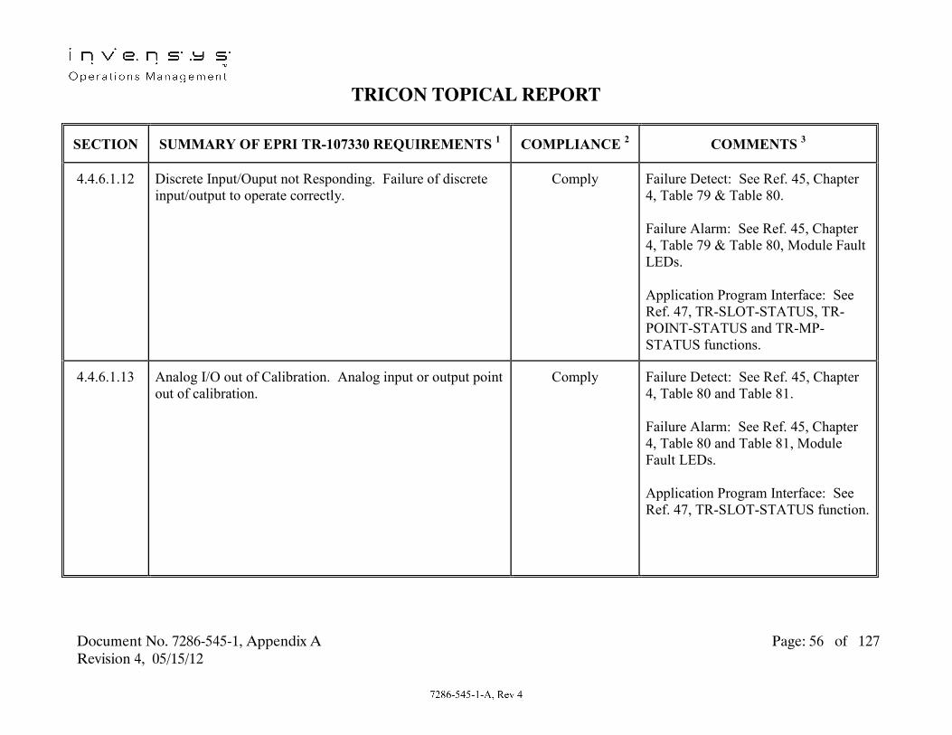
TRICON TOPICAL REPORT
Document No. 7286-545-1, Appendix A Page: 56 of 127 Revision 4, 05/15/12
SECTION SUMMARY OF EPRI TR-107330 REQUIREMENTS 1 COMPLIANCE 2 COMMENTS 3
4.4.6.1.12 Discrete Input/Ouput not Responding. Failure of discrete input/output to operate correctly.
Comply Failure Detect: See Ref. 45, Chapter 4, Table 79 & Table 80. Failure Alarm: See Ref. 45, Chapter 4, Table 79 & Table 80, Module Fault LEDs. Application Program Interface: See Ref. 47, TR-SLOT-STATUS, TR-POINT-STATUS and TR-MP-STATUS functions.
4.4.6.1.13
Analog I/O out of Calibration. Analog input or output point out of calibration.
Comply Failure Detect: See Ref. 45, Chapter 4, Table 80 and Table 81. Failure Alarm: See Ref. 45, Chapter 4, Table 80 and Table 81, Module Fault LEDs. Application Program Interface: See Ref. 47, TR-SLOT-STATUS function.

TRICON TOPICAL REPORT
Document No. 7286-545-1, Appendix A Page: 57 of 127 Revision 4, 05/15/12
SECTION SUMMARY OF EPRI TR-107330 REQUIREMENTS 1 COMPLIANCE 2 COMMENTS 3
4.4.6.1.14 Power Supply out of Tolerance. Power supply to PLC is interrupted or a chassis power supply module fails.
Comply Failure Detect: See Ref. 45, Chapter 4, Table 77 & Table 78. Failure Alarm: See Ref. 45, Chapter 4, Table 77 & Table 78, Module Fault LEDs. Application Program Interface: See Ref. 47, TR-CHASSIS-STATUS function.
4.4.6.2 On-Line Self-Test Requirements. On-line self-tests shall cover at least items 4.4.6.1.1 through 4.4.6.1.6 above. Results shall be made available to the application program.
Comply See Ref. 42, Section 8.1.3. See Table sections 4.4.6.1.1 through 4.4.6.1.6 above.
4.4.6.3 Power Up Diagnostics Requirements. Power up diagnostics shall include all on-line self tests, configuration verification, and test of failure to complete a scan. Application program execution shall be inhibited if power up diagnostics detect a failure.
Comply See Ref. 42, Sections 8.1.3. The Power Up diagnostics and initializations are followed by execution of the background runtime diagnostics and fault analysis functions, which include the on-line self tests identified in Table Section 4.4.6.2.
4.4.7 Data and Data Base. (section heading) - - - No requirements.

TRICON TOPICAL REPORT
Document No. 7286-545-1, Appendix A Page: 58 of 127 Revision 4, 05/15/12
SECTION SUMMARY OF EPRI TR-107330 REQUIREMENTS 1 COMPLIANCE 2 COMMENTS 3
4.4.7.1 Data and Data Base Overview. Descriptive information. - - - No requirements.
4.4.7.2 Data and Data Base Requirements. Descriptive information.
- - - No requirements.
4.4.7.2.A Data and Data Base Requirements. PLC shall support use of user-defined program constants that are contained in non-volatile memory. Features shall confirm that constants in redundant processors are the same.
Comply See Ref. 46, Application Development. See Ref. 45, Table 8, memory is battery backed. See Ref. 42, Section 8.1.3, constants in memory are continuously verified.
4.4.7.2.B Data and Data Base Requirements. PLC shall provide functions to read and modify data base constants. Features shall confirm that modified constants are consistent between redundant processors.
Comply See Ref. 46, Application Development. See Ref. 42, Section 8.1.3, constants in memory are continuously verified.
4.4.7.2.C Data and Data Base Requirements. PLC shall provide features to prevent modifications to data base constants over connected communication paths.
Comply See Ref. 46, Project Administration.
4.4.7.2.D
Data and Data Base Requirements. PLC shall provide features to permit transmitting input, outputs and calculated values to other devices over a serial port.
Comply See Ref. 15.

TRICON TOPICAL REPORT
Document No. 7286-545-1, Appendix A Page: 59 of 127 Revision 4, 05/15/12
SECTION SUMMARY OF EPRI TR-107330 REQUIREMENTS 1 COMPLIANCE 2 COMMENTS 3
4.4.8 Other Non-Ladder Logic Programming Languages. (section heading)
- - - No requirements.
4.4.8.1 Requirements for Sequential Logic Languages. Sequential logic language other than ladder logic may be used. Language shall provide capabilities given in Section 4.4.3. Language must support tools with features given in Section 4.4.4.
Comply See Ref. 46, Application Development. Tristation 1131 also provides Function Block Diagram and Structured Text languages for application development. All discussions in Table Sections 4.4.3 and 4.4.4 apply to these languages as well.
4.4.8.2 Standard High Level Languages. (section heading) - - - No requirements.
4.4.8.2.1 Overview of Standard High Level Languages. Descriptive information.
- - - No requirements.
4.4.8.2.2 Requirements for Standard High Level Languages. Required capabilities of supported standard high level programming languages.
N/A Tricon does not support use of standard high level programming languages.
4.4.9
Sequence of Events Processing Requirements. Descriptive information.
- - - No requirements.

TRICON TOPICAL REPORT
Document No. 7286-545-1, Appendix A Page: 60 of 127 Revision 4, 05/15/12
SECTION SUMMARY OF EPRI TR-107330 REQUIREMENTS 1 COMPLIANCE 2 COMMENTS 3
4.4.9.A Sequence of Events. Shall permit application program to capture, store and time tag up to 20 transitions of up to 50 different discrete events of inputs or application objects.
Comply See Ref. 48, Chapter 3. A single SOE block (or list of discrete variables) will support recording of 100,000 events.
4.4.9.B Sequence of Events. Shall permit starting and stopping the event recording.
Comply See Ref. 48, Chapter 2,. SOESTRT and SOESTOP commands.
4.4.9.C Sequence of Events. Shall permit transmitting the data to an external device using a PLC communication port.
Comply See Ref. 46, Introduction. Supports transmission of data through TCM.
4.4.9.D Sequence of Events. Relative accuracy of time tags shall be one scan cycle ± 50 msecs.
Comply See Ref. 46, , Using Time Synchronization. Accuracy of time tags is one scan cycle ± 25 msecs
4.4.10 System Integration Requirements. An appropriate level of system integration and integration testing shall be applied to the test specimen and TSAP.
Comply See Table Section 5.2.C.
4.5 Human/Machine Interface (HMI). (section heading) - - - No requirements.
4.5.1 Human/Machine Interface (HMI) Background. Descriptive information.
- - - No requirements.
4.5.2 Requirements for Human/Machine Interface Functions. Descriptive information.
- - - No requirements.

TRICON TOPICAL REPORT
Document No. 7286-545-1, Appendix A Page: 61 of 127 Revision 4, 05/15/12
SECTION SUMMARY OF EPRI TR-107330 REQUIREMENTS 1 COMPLIANCE 2 COMMENTS 3
4.5.2.A HMI Functions. PLC shall support switching a loop controller between manual and automatic via switch inputs. For control loops with integral action, auto/manual tracking shall be provided.
Comply See Ref. 47, LEADLAG and PID function descriptions. See Ref. 15.
4.5.2.B HMI Functions. PLC shall support setpoint adjustments via switch inputs. Adjustments shall include increase, decrease, and rate of change of setpoint.
Comply See Ref. 15.
4.5.2.C HMI Functions. PLC shall support manual initiation of equipment via switch inputs. PLC shall support detection of manually initiated equipment.
Comply See Ref. 15.
4.5.2.D HMI Functions. PLC shall support display of status of discrete and continuous value parameters via connected devices.
Comply See Ref. 15.
4.5.2.E
HMI Functions. PLC shall support sending information to a serial port device. Information sent shall include input, output and internal variable values, on-line diagnostics, sequence of events (SOE) data, and results of calculations, comparisons and bit manipulations.
Comply See Ref. 15.

TRICON TOPICAL REPORT
Document No. 7286-545-1, Appendix A Page: 62 of 127 Revision 4, 05/15/12
SECTION SUMMARY OF EPRI TR-107330 REQUIREMENTS 1 COMPLIANCE 2 COMMENTS 3
4.5.3 Requirements for Interactive Features. The PLC shall provide mechanisms to prevent unauthorized access to or inadvertent use of on-line functions. Interactive features shall be available through a programming, maintenance and debugging port. PLC shall operate with no connection to this port. PLC shall mask interactive commands during run mode.
Comply
Comply
Comply
See Ref. 13, Chassis Options. See Ref. 46. See Ref. 13, Chassis Options.
4.5.4 Requirements for Operator Action System Response Times. For any operator action that requires PLC confirmation, the PLC shall include features to enable confirmation within 0.5 seconds.
Comply See Ref. 47. As an example, a discrete input to discrete output sequence with intervening internal timer function would meet this requirement.
4.5.5 Display Requirements. LEDs are acceptable for any status displays.
Comply See Ref. 45, Chapter 4.
4.5.6 Alarm Processing Requirements. Descriptive information. - - - No requirements.
4.5.6.A Alarm Processing. PLC shall have ability to compare inputs or derived parameters to setpoints.
Comply See Ref. 15.

TRICON TOPICAL REPORT
Document No. 7286-545-1, Appendix A Page: 63 of 127 Revision 4, 05/15/12
SECTION SUMMARY OF EPRI TR-107330 REQUIREMENTS 1 COMPLIANCE 2 COMMENTS 3
4.5.6.B Alarm Processing. PLC shall have ability to latch an alarm condition and reset based on alarm reset condition.
Comply See Ref. 15.
4.5.6.C Alarm Processing. PLC shall have ability to blink an output indicator.
Comply See Ref. 47, BLINK function. As an example, a discrete output driven by a BLINK coil would meet this requirement.
4.5.6.D Alarm Processing. PLC shall have ability to acknowledge an alarm.
Comply See Ref. 46, LATCH coil function. As an example, a discrete input connected to a LATCH coil would meet this requirement.
4.5.6.E Alarm Processing. Application program shall have ability to capture results of self-diagnostics.
Comply See Ref. 46. As an example, TR_xxx_STATUS functions return diagnostic status of system hardware to application program.
4.5.6.F Alarm Processing. Application program shall have ability to store results of items A through E in a buffer and transmit the data via a communication port.
Comply See Ref. 45, Chapter 2, Page 38, As an example, Sequence of Events utility can store and transmit alarm information.
4.5.7 Hard Manual Backup. Descriptive information. - - - No requirements.
4.6 Electrical. (section header) - - - No requirements.

TRICON TOPICAL REPORT
Document No. 7286-545-1, Appendix A Page: 64 of 127 Revision 4, 05/15/12
SECTION SUMMARY OF EPRI TR-107330 REQUIREMENTS 1 COMPLIANCE 2 COMMENTS 3
4.6.1 Power Supply Requirements. (section heading) - - - No requirements.
4.6.1.1 PLC Power Sources and Power Supply Requirements. Descriptive information.
- - - No requirements.
4.6.1.1.A
Power Sources. AC sources shall operate from at least 90 Vac to 150 Vac and 57 to 63 Hz. AC sources shall operate at the temperature and humidity range given in Section 4.3.6.
Exception
Comply
See Ref. 45 and 49. Model 8310 AC power supply modules are rated for 85 to 140 Vac input. See Ref. 35. Model 8310 AC power supply modules were tested as per required temperature and humidity range (see Table Section 4.3.6.3).

TRICON TOPICAL REPORT
Document No. 7286-545-1, Appendix A Page: 65 of 127 Revision 4, 05/15/12
SECTION SUMMARY OF EPRI TR-107330 REQUIREMENTS 1 COMPLIANCE 2 COMMENTS 3
4.6.1.1.B Power Sources. DC sources shall operate from at least 20.4 to 27.6 Vdc. DC sources shall operate at the temperature and humidity range given in Section 4.3.6.
Exception
Comply
See Ref. 45 and 49. Model 8311 DC power supply modules are rated for 22 to 31 Vdc input. See Ref. 35. Model 8311 DC power supply modules were tested as per required temperature and humidity range (see Table Section 4.3.6.3).
4.6.1.1.C Power Sources. DC sources shall operate for seven days from a 30 VDC source.
Comply See Ref. 19 Section 10.18.
4.6.1.1.D Power Sources. Sources shall be capable of supplying 1.2 times bus loading for a fully loaded main chassis.
Comply See Ref. 49, Page 24.
4.6.1.1.E Power Sources. Sources shall be capable of supplying 1.2 times bus loading for a fully loaded expansion chassis.
Comply See Ref. 49 Page 24.
4.6.1.1.F
Power Sources. Hold up time for AC supplied power sources shall be 40 msec.
Comply Ref. 53, Section 7.

TRICON TOPICAL REPORT
Document No. 7286-545-1, Appendix A Page: 66 of 127 Revision 4, 05/15/12
SECTION SUMMARY OF EPRI TR-107330 REQUIREMENTS 1 COMPLIANCE 2 COMMENTS 3
4.6.1.1.G Power Sources. Sources shall meet the EMI/RFI, surge withstand and ESD requirements of Sections 4.3.7, 4.6.2 and 4.3.8. Sources shall meet the grounding requirements of Section 4.6.8.
Comply
Comply
See Ref. 37, Ref. 39 and Ref. 40. See Table Section 4.6.8.
4.6.1.1.H Power Sources. Requirements for fan cooled power sources.
N/A See Ref. 45, Chapter 3, Page 170. Tricon power supplies are convection cooled.
4.6.1.1.I Power Sources. Faults in redundant power sources shall not prevent operation of the alternate supply.
Comply See Ref. 45, Page 32. Redundant power sources are independently fused.
4.6.1.2
Loop Power Supply Requirements. Power supply modules shall be provided for external devices. Modules shall provide at least 500 mA at 24 VDC. The modules shall meet requirements A, B, C, F. G and H above.
N/A No third party power supplies were included in the qualification program.

TRICON TOPICAL REPORT
Document No. 7286-545-1, Appendix A Page: 67 of 127 Revision 4, 05/15/12
SECTION SUMMARY OF EPRI TR-107330 REQUIREMENTS 1 COMPLIANCE 2 COMMENTS 3
4.6.2 Surge Withstand Capability Requirements. PLC platform shall withstand IEEE Standard C62.41 ring wave and combination wave, 3000 volt peak surges. Withstand capability applies to power sources, analog and discrete I/O interfaces, and communication port interfaces. Per Section 6.3.5, surge testing shall be conducted per IEEE Standard C62.45.
Comply
Partial Exception
See Ref. 39 and 57. Power sources meet surge withstand criteria- Circuits were tested to IEC 61000-4-5 and IEC 61000-4-12 using 1 kV Ring wave, and combination waves at 1kV open circuit/0.5kA short circuit per R.G. 1.180, Rev. 1, Level 2. All circuits met TR Section 4.6.2 acceptance criteria.
Power Sources were tested per Reg Guide 1.180 Rev. 1 for category B low exposure installations to 2KV. IEEE Standards 62.41 and 62.45 do not address testing of I/O and communication circuits; these circuits were tested per Reg. Guide 1.180 Rev. 1 for low exposure level 2 installations at 1KV. Tests were performed to IEC61000-4-5 for Combination Wave and 61000-4-12 for Ring Wave.
4.6.3
Separation. Descriptive information. - - - No requirements.

TRICON TOPICAL REPORT
Document No. 7286-545-1, Appendix A Page: 68 of 127 Revision 4, 05/15/12
SECTION SUMMARY OF EPRI TR-107330 REQUIREMENTS 1 COMPLIANCE 2 COMMENTS 3
4.6.4 Class 1E/Non-1E Isolation Requirements. The PLC modules shall provide isolation of at least 600 Vac and 250 Vdc applied for 30 seconds. Isolation features shall conform to IEEE 384. Isolation testing shall be performed on the modules.
Exception See Ref. 41. Only relay output modules, communication ports, and fiber optic chassis inter- connections are intended to provide Class 1E to Non-1E isolation. Isolation tests were performed on relay output module and communication ports. Relay output module meets TR Section 4.6.4 isolation requirements. Communication ports provide isolation to 250 Vac and 250 Vdc for 30 seconds. Fiber optic chassis connections inherently provide isolation through non-conducting fiber optic cables.
4.6.5
Cable/Wiring Requirements. Manufacturer shall supply all PLC hardware interconnecting cabling. All cabling shall be suitable for UL Class 2 service. Specifically, withstand rating shall be larger of 3 times the signal level voltage or 150 volts. Temperature rating shall be 60ºC or greater. Vendor shall identify the quantities of PVC type wire and cable used in the system.
Comply See Ref. 49 and 61 Chassis-to-chassis and chassis-to-termination panel interconnect cables are rated for 300 VAC and a minimum of 80ºC. Cable jackets are made of PVC or XLPE.

TRICON TOPICAL REPORT
Document No. 7286-545-1, Appendix A Page: 69 of 127 Revision 4, 05/15/12
SECTION SUMMARY OF EPRI TR-107330 REQUIREMENTS 1 COMPLIANCE 2 COMMENTS 3
4.6.6 Termination Requirements. Modules shall be able to be removed without disconnecting field wiring. Features shall be provided to substitute test signals or monitoring instruments for field connections. Connectors to the PLC shall have positive hold down mechanisms. Connectors and terminations to the PLC shall be qualified with the generic PLC.
Comply
Comply
Comply
See Ref. 48.. See Ref. 45 and 48
See Ref. 3. Field termination panels were included in the qualification test specimen.
4.6.7 Backup Power. Descriptive information. - - - No requirements.
4.6.8 Grounding/Shielding Requirements. The PLC equipment shall meet IEEE 1050 and EPRI TR-102323 grounding requirements. This includes supporting connection to single point, multi-point and floating ground systems, and providing separate ground connection points on each chassis for AC ground, DC ground, and signal ground. The PLC equipment shall meet IEEE 1050 and EPRI TR-102323 shielding requirements. This includes providing shielding connection points for the I/O module field terminations.
Comply
Comply
See Ref. 45, Chapter 3. See Ref. 45, Chapter 3.
4.7 Maintenance. (section heading) - - - No requirements.

TRICON TOPICAL REPORT
Document No. 7286-545-1, Appendix A Page: 70 of 127 Revision 4, 05/15/12
SECTION SUMMARY OF EPRI TR-107330 REQUIREMENTS 1 COMPLIANCE 2 COMMENTS 3
4.7.1 Maintenance Background. Descriptive information. - - - No requirements.
4.7.2 Diagnosis/Built-in Testability Requirements. Descriptive information.
- - - No requirements.
4.7.3 Module Replacement Requirements. The PLC shall contain features to aid in module replacement. The maintenance manual shall contain a description of any hardware configuration item for each module. The module hold downs shall be easily accessible and provide ease of removal and reinstallation.
Comply
Comply
Comply
See Ref. 45, Chapter 3. See Ref. 45, Chapter 3. See Ref. 45, Chapter 3.
4.7.4
Preventive Maintenance Requirements. Equipment manuals shall contain preventive maintenance information. Preventive maintenance shall also include components identified in Section 4.7.8.2.
Comply See Ref. 45, Chapter 3. See Table Section 4.7.8.2.

TRICON TOPICAL REPORT
Document No. 7286-545-1, Appendix A Page: 71 of 127 Revision 4, 05/15/12
SECTION SUMMARY OF EPRI TR-107330 REQUIREMENTS 1 COMPLIANCE 2 COMMENTS 3
4.7.5 Surveillance Testing Requirements. The PLC shall support IEEE 338 surveillance testing through: - Ability to read input, intermediate and output values. - Ability to force output values. - Ability to make connections to all I/O signals. - Ability to program I/O operations. Features and procedures shall be provided that permit detection of failures of all redundant components if those failures are not detectable by self-diagnostics or are masked by redundant channel behavior.
Comply
N/A
See Ref. 49, Page 59. Tristation 1131 connection permits required access to application program variables. Also, screw terminals used on field termination panels can be loosened for connection to all I/O signals. See Ref. 45, Chapter 4. All failures of redundant devices are indicated by module fault LEDs.
4.7.6
Output Bypass/Control Devices. Descriptive information. - - - No requirements.

TRICON TOPICAL REPORT
Document No. 7286-545-1, Appendix A Page: 72 of 127 Revision 4, 05/15/12
SECTION SUMMARY OF EPRI TR-107330 REQUIREMENTS 1 COMPLIANCE 2 COMMENTS 3
4.7.7 Hot Repair Capability. The PLC shall support installing I/O modules with backplane power applied. Low power modules shall support removal with field power applied. When output modules are removed from the backplane, the state of the outputs should be known.
Comply
Comply
N/A
See Ref. 45, Chapter 3 See Ref. 45, Chapter 3. Modules can be “hot-swapped” with field power applied. Active modules shall not be removed from a chassis. An active module can be replaced on-line through insertion of a similar module in the adjoining spare slot and after bumpless transfer of control to the spare module. Removal of an output module from the chassis results in disconnection of all field wiring from the module.
4.7.8
Manufacturer System Life Cycle Maintenance. (section heading)
- - - No requirement.

TRICON TOPICAL REPORT
Document No. 7286-545-1, Appendix A Page: 73 of 127 Revision 4, 05/15/12
SECTION SUMMARY OF EPRI TR-107330 REQUIREMENTS 1 COMPLIANCE 2 COMMENTS 3
4.7.8.1 Parts Replacement Life Cycle Requirements. The baseline configuration of the qualified PLC shall be established. Records shall be maintained for revision history and changes. Records shall be maintained for tracking failures. Testing shall be performed as necessary to maintain a qualified platform based on future revisions or replacements.
Comply
Comply
Comply
Comply
See Ref. 3. See Ref. 62, QAM 4.0, Design Control. See Table Section 7.8. See Ref. 63.
4.7.8.2 Component Aging Analysis Requirements. A periodic surveillance and maintenance interval shall be determined per IEEE 323 to account for any significant aging mechanisms.
Comply See this report, Section 2.2.15.
4.7.9 Maintenance Human Factors. Descriptive information. - - - No requirements.
4.7.9.A
Special PLC Manufacturer Equipment. The manufacturer shall provide documentation for PLC support equipment.
N/A See Ref. 45, Chapter 3. No special tools required for routine maintenance.

TRICON TOPICAL REPORT
Document No. 7286-545-1, Appendix A Page: 74 of 127 Revision 4, 05/15/12
SECTION SUMMARY OF EPRI TR-107330 REQUIREMENTS 1 COMPLIANCE 2 COMMENTS 3
4.7.9.B Test Equipment Connections. Test equipment connections shall be supported by documentation and hardware, including interconnection devices. The manufacturer shall provide any special instruction for use of test equipment connections.
Comply See Ref. 45, Chapter 3. This section provides instruction and precautions for connection and use of Tristation 1131 to perform recommended routine maintenance activities.
4.7.9.C Job Aids. Aids for operating the PLC equipment shall be provided.
Comply See various sections of Ref. 45 for equipment pictures, and operational recommendations and warnings. See Ref. 45, Chapter 3 for description of module installation keying.
4.7.9.D Help Screens. Help screens for software used to support maintenance shall be provided.
Comply See Ref. 45. Tristation 1131 software may be used during maintenance.
4.8 Requirements for Third Party/Sub-Vendor Items. All items provided by sub-vendors or third parties shall be subjected to all applicable requirements and tests. Compatibility of operation with the PLC shall be demonstrated through tests.
Comply See Ref. 56. Third party signal conditioners were included in the qualification program.
4.9 Other. (section heading) - - - No requirements.
4.9.1
Data Handling and Communication Interface Overview. Descriptive information.
- - - No requirements.
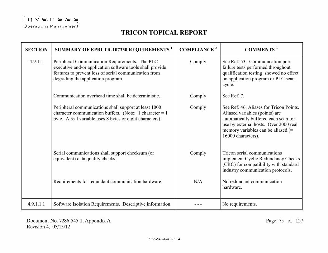
TRICON TOPICAL REPORT
Document No. 7286-545-1, Appendix A Page: 75 of 127 Revision 4, 05/15/12
SECTION SUMMARY OF EPRI TR-107330 REQUIREMENTS 1 COMPLIANCE 2 COMMENTS 3
4.9.1.1
Peripheral Communication Requirements. The PLC executive and/or application software tools shall provide features to prevent loss of serial communication from degrading the application program. Communication overhead time shall be deterministic. Peripheral communications shall support at least 1000 character communication buffers. (Note: 1 character = 1 byte. A real variable uses 8 bytes or eight characters). Serial communications shall support checksum (or equivalent) data quality checks. Requirements for redundant communication hardware.
Comply
Comply
Comply
Comply
N/A
See Ref. 53. Communication port failure tests performed throughout qualification testing showed no effect on application program or PLC scan cycle. See Ref. 7. See Ref. 46, Aliases for Tricon Points. Aliased variables (points) are automatically buffered each scan for use by external hosts. Over 2000 real memory variables can be aliased (= 16000 characters). Tricon serial communications implement Cyclic Redundancy Checks (CRC) for compatibility with standard industry communication protocols. No redundant communication hardware.
4.9.1.1.1 Software Isolation Requirements. Descriptive information. - - - No requirements.

TRICON TOPICAL REPORT
Document No. 7286-545-1, Appendix A Page: 76 of 127 Revision 4, 05/15/12
SECTION SUMMARY OF EPRI TR-107330 REQUIREMENTS 1 COMPLIANCE 2 COMMENTS 3
4.9.1.1.1.A Software Isolation. Features shall be provided to permit sending serial port data with no hardware or software handshaking.
Comply See Ref. 46, Configurable Modules (TCM), and Peer-to-Peer Communication.
4.9.1.1.1.B Software Isolation. Features shall be provided to permit the application program to ignore communication port incoming data.
Comply See Ref. 46, Configurable Modules (TCM), and Peer-to-Peer Communication.
4.9.1.1.1.C Software Isolation. Software shall permit use of the send data functions with the receive data functions disabled.
Comply See Ref. 46, Configurable Modules (TCM), and Peer-to-Peer Communication.
4.9.1.1.1.D
Software Isolation. Features shall be provided to disable interrupts caused by full serial port receive buffers.
Comply See Ref. 58. No interrupts to main processors are generated based on communication buffer full interrupts.

TRICON TOPICAL REPORT
Document No. 7286-545-1, Appendix A Page: 77 of 127 Revision 4, 05/15/12
SECTION SUMMARY OF EPRI TR-107330 REQUIREMENTS 1 COMPLIANCE 2 COMMENTS 3
4.9.1.
PLC Peer-to-Peer Communication Requirements. Peer-to-peer link shall meet requirements of Section 4.3.4.4, except item B. Communication time shall be deterministic. Communication errors shall not affect other portions of the application program or inhibit the PLC scan cycle. Queues for communicated data shall be supported and queue status shall be available to the communication program. Loss of communication shall be detected and made available to the application program. Use of the peer-to-peer communication link shall support the response time requirement given in Section 4.2.1.A.
Comply
Comply
Comply
Comply
See Ref. 45, Section 3.8, TCM Module, Net 1 port. Tricon Peer-to-Peer protocol is proprietary. See Ref. 8. Net 1 port surge withstand capability meets IEC 801-5 “basic immunity” levels.
See Ref. 46, Peer-to-Peer Communication Data Transfer Time. See Ref. 64. TCM Module Net 1 port failure tests showed no effect on application program or PLC scan cycle. See Ref. 46, Peer-to-Peer Communication. See Ref. 20, Section 3 and Table Section 4.2.1.A. Peer-to-Peer communication link was implemented during all qualification testing.

TRICON TOPICAL REPORT
Document No. 7286-545-1, Appendix A Page: 78 of 127 Revision 4, 05/15/12
SECTION SUMMARY OF EPRI TR-107330 REQUIREMENTS 1 COMPLIANCE 2 COMMENTS 3
4.9.2 Overall System Security Requirements. Switching the main processor from RUN mode to other modes shall be by keylock switch. Features shall ensure that redundant components operate in the same mode, and that program changes are loaded into all redundant processors. Provisions shall prevent modification of the application program and operating system while the PLC in on-line.
Comply
Comply
Comply
See Ref. 45, Chapter 2. See Ref. 45, Chapter 2, Main Processor Modules. See Ref. 46, Chapter 5. See Ref. 45, Chapter 2, Page 28 and Ref. 46, System Administration, Elements of a Security System.
4.9.3 Heartbeat Requirements. The PLC shall provide capability to activate a “heartbeat” external to the PLC.
Comply See Ref. 15.
4.9.4 Hazardous Materials Requirements. Material data sheets shall be provided for all hazardous materials associated with the PLC.
N/A No hazardous materials associated with the Tricon PLC.
4.10 Shipping and Handling Requirements. Packaging and shipping shall be in accordance with ANSI N45.2.2.
Comply See Ref. 54, Section QAM 15.0, Handling, Storage, Packaging Preservation, and Delivery.
4.10.1 Packaging Requirements. Descriptive information. - - - No requirements.

TRICON TOPICAL REPORT
Document No. 7286-545-1, Appendix A Page: 79 of 127 Revision 4, 05/15/12
SECTION SUMMARY OF EPRI TR-107330 REQUIREMENTS 1 COMPLIANCE 2 COMMENTS 3
4.10.1.A Items Shipped. Shall be packaged to avoid damage or degradation due to various environmental and handling factors which may be encountered during shipping and storage.
Comply See Ref. 54, Section QAM 15.0, Handling, Storage, Packaging Preservation, and Delivery.
4.10.1.B Items Shipped. Packaging shall include desiccant materials as required.
Comply See Ref. 54, Section QAM 15.0, Handling, Storage, Packaging Preservation, and Delivery.
4.10.1.C Items Shipped. Items shall be inspected for cleanliness prior to packaging. Items not immediately packaged shall be protected from contamination.
Comply See Ref. 54, Section QAM 15.0, Handling, Storage, Packaging Preservation, and Delivery. See Ref. 54, Section QAM 10.0, Inspection and Testing.
4.10.1.D Items Shipped. Cushioning shall be provided to protect against shock and vibration.
Comply See Ref. 54, Section QAM 15.0, Handling, Storage, Packaging Preservation, and Delivery.
4.10.1.E Items Shipped. Items and containers shall be marked with appropriate identification.
Comply See Ref. 54, Section QAM 15.0, Handling, Storage, Packaging Preservation, and Delivery. See Ref. 54, Section QAM 8.0, Product, Parts, and Material Identification and Traceability.

TRICON TOPICAL REPORT
Document No. 7286-545-1, Appendix A Page: 80 of 127 Revision 4, 05/15/12
SECTION SUMMARY OF EPRI TR-107330 REQUIREMENTS 1 COMPLIANCE 2 COMMENTS 3
4.10.1.F Items Shipped. Copies of packing lists shall be included with each carton shipped.
Comply See Ref. 54, Section QAM 15.0, Handling, Storage, Packaging Preservation, and Delivery.
4.10.1.G Items Shipped. ESD sensitive items shall be appropriately packaged, handled and marked.
Comply See Ref. 54, Section QAM 15.0, Handling, Storage, Packaging Preservation, and Delivery.
4.10.1.H Items Shipped. Packaging shall be suitable for movement using hand trucks.
Comply See Ref. 54, Section QAM 15.0, Handling, Storage, Packaging Preservation, and Delivery.
4.10.1.I Items Shipped. Special handling or storage requirements shall be marked on the containers.
Comply See Ref. 54, Section QAM 15.0, Handling, Storage, Packaging Preservation, and Delivery.
4.10.1.J Items Shipped. See Section 4.4.2 for requirements for software storage media.
Comply See Table Section 4.4.2.
4.10.2
Shipping Requirements. Requirements for mode of shipping, use of fully enclosed vehicles, special handling and stacking instructions as necessary, and container markings and protective covers.
Comply See Ref. 54, Section QAM 15.0, Handling, Storage, Packaging Preservation, and Delivery.

TRICON TOPICAL REPORT
Document No. 7286-545-1, Appendix A Page: 81 of 127 Revision 4, 05/15/12
SECTION SUMMARY OF EPRI TR-107330 REQUIREMENTS 1 COMPLIANCE 2 COMMENTS 3
4.10.3 Storage Requirements. Storage and shelf life requirements shall be provided for all PLC items.
Comply See Ref. 54, Section QAM 15.0, Handling, Storage, Packaging Preservation, and Delivery.
5 Acceptance/Operability Testing. Descriptive information. - - - No requirements.
5.1 Acceptance/Operability Testing Overview. The development, design and performance of acceptance testing shall use the documentation requirements of Section 8.14.
Comply See Table Section 8.14.
5.2 Pre-Qualification Acceptance Test Requirements. Descriptive information.
- - - No requirements.
5.2.A Application Objects Testing. Testing of the software objects in the PLC library shall be performed. This testing shall be in addition to any testing performed by the manufacturer.
Exception See Ref. 2, Section 5. Triconex and TUV Rheinland have performed extensive testing of the Tricon PLC application software. Results of this testing are documented in Ref. 58. Accordingly, this testing was not performed.
5.2.B Initial PLC Calibration. The generic qualification sample PLC shall be calibrated to NIST traceable sources.
Comply See Ref. 19, Section 9.0.
5.2.C System Integration. System integration testing portion of TSAP V&V shall be performed during acceptance testing.
Comply See Ref. 65.

TRICON TOPICAL REPORT
Document No. 7286-545-1, Appendix A Page: 82 of 127 Revision 4, 05/15/12
SECTION SUMMARY OF EPRI TR-107330 REQUIREMENTS 1 COMPLIANCE 2 COMMENTS 3
5.2.D Operability Tests. The Operability Test shall be performed during acceptance testing.
Comply See Ref. 53.
5.2.E Prudency Tests. The Prudency Test shall be performed during acceptance testing.
Comply See Ref. 66.
5.2.F Burn-In Test. A minimum 352 hour burn-in test shall be performed during acceptance testing.
Exception See Ref. 2, Appendix 3. Triconex routinely conducts burn-in tests on all Tricon hardware as part of manufacturing process. This testing meets TR requirements for burn-in testing. Accordingly, this testing was not performed.
5.3 Operability Test Requirements. Descriptive information. - - - No requirements.
5.3.A
Accuracy. Accuracy checks shall be performed on the analog input/output modules.
Comply See Ref. 20, Section 2.

TRICON TOPICAL REPORT
Document No. 7286-545-1, Appendix A Page: 83 of 127 Revision 4, 05/15/12
SECTION SUMMARY OF EPRI TR-107330 REQUIREMENTS 1 COMPLIANCE 2 COMMENTS 3
5.3.B Response Time. Response time of analog input to digital output and digital input to digital output sequences shall be measured. For baseline (acceptance) testing, the acceptance criteria is that the measured response time shall not vary more than 20% from the value calculated from manufacturer’s data. For all subsequent testing, the measured value shall not vary more than 10% from the baseline.
Exception See Ref. 20, Section 3. Based on Tricon design, it is not practicable to perform a test that provides consistent (within ±20%) measured response times. Instead, manufacturer’s data is used to calculate maximum expected AI to DO and DI to DO response times. The acceptance criteria for all tests is that the calculated response times are not exceeded.
5.3.C Discrete Input Operability. Discrete inputs shall be tested for capability to detect changes in the inputs.
Comply See Ref. 20, Section 4.
5.3.D
Discrete Output Operability. Discrete outputs shall be tested for ability to operate within rated voltages and currents.
Comply See Ref. 20, Section 5.

TRICON TOPICAL REPORT
Document No. 7286-545-1, Appendix A Page: 84 of 127 Revision 4, 05/15/12
SECTION SUMMARY OF EPRI TR-107330 REQUIREMENTS 1 COMPLIANCE 2 COMMENTS 3
5.3.E Communication Operability. If any communication functions are included in the qualification envelope, then operability of the ports shall be tested. Tests shall look for degradation in bit rates, signal levels and pulse shapes of communication protocol.
Partial Exception See Ref. 20, Section 1. The TCM Module NET1 and NET2 ports are included in the qualification envelope. Test equipment to measure degradation of bit rates, pulse shapes, and signal levels was not available at the time testing was performed. The port protocol is proprietary and not amenable to TR specified tests-. Port operation is monitored for correct performance throughout all qualification tests.
5.3.F Coprocessor Operability. If any coprocessors are included in the qualification envelope, then tests shall be performed specifically on these coprocessors.
Comply See Ref. 20. Section 1. Operation of Tricon coprocessors is invoked automatically during application program execution. Separate coprocessor tests are not required.
5.3.G Timer Tests. Accuracy of timer functions shall be tested. Comply See Ref. 20, Section 6.
5.3.H Test of Failure to Complete Scan Detection. The function of the mechanism to detect failure to complete a scan shall be tested. The power up testing of this feature may be used to establish its operability.
Comply See Ref. 20, Section 8.

TRICON TOPICAL REPORT
Document No. 7286-545-1, Appendix A Page: 85 of 127 Revision 4, 05/15/12
SECTION SUMMARY OF EPRI TR-107330 REQUIREMENTS 1 COMPLIANCE 2 COMMENTS 3
5.3.I Failover Operability Tests. If redundancy with automatic transfer to a redundant device is used, tests shall be performed to establish operability of the failover hardware.
Comply See Ref. 20, Section 7.
5.3.J Loss of Power Test. The AC and DC power sources shall be shut off for at least 30 seconds and reapplied.
Comply See Ref. 20, Section 8.
5.3.K Power Interrupt Test. The AC power sources shall be interrupted for a 40 millisecond hold-up time.
Comply See Ref. 20, Section 9.
5.4 Prudency Testing Requirements. The Prudency tests shall be performed with the power supply sources at the minimum values specified in Section 4.6.1.1.
Partial Exception See Ref. 21, Section 2, Subsection 3.1. To accommodate power frequency changes, external power to the 230Vac chassis power supplies was provided through a step-up transformer which was fed by the same external power supply for the 115Vac chassis power supplies. This limited the voltage to the 115Vac chassis power supplies to 97Vac.
5.4.A Burst of Events Test. Tests shall be performed to verify operation of the PLC under highly dynamic input/output variation conditions.
Comply See Ref. 21, Section 2.

TRICON TOPICAL REPORT
Document No. 7286-545-1, Appendix A Page: 86 of 127 Revision 4, 05/15/12
SECTION SUMMARY OF EPRI TR-107330 REQUIREMENTS 1 COMPLIANCE 2 COMMENTS 3
5.4.B Failure of Serial Port Receiver Test. The receiving device connected to the main processor serial communication port shall be simulated to fail in various modes. PLC response time shall be verified to not degrade unacceptably.
Comply See Ref. 21, Section 3.
5.4.C Serial Port Noise Test. The transmit line to the main processor serial communication port shall be subjected to white noise. PLC response time shall be verified to not degrade unacceptably.
Comply See Ref. 21, Section 3.
5.4.D
Fault Simulation. For PLC’s that include redundancy, failures in redundant elements shall be simulated.
Comply See Ref. 20, Section 1, Subsection 3.0, and Ref. 6, Section 7. Fault simulation in redundant elements is performed during the Failover portion of Operability testing, in lieu of during Prudency Testing..

TRICON TOPICAL REPORT
Document No. 7286-545-1, Appendix A Page: 87 of 127 Revision 4, 05/15/12
SECTION SUMMARY OF EPRI TR-107330 REQUIREMENTS 1 COMPLIANCE 2 COMMENTS 3
5.5 Operability/Prudency Testing Applicability Requirements. As a minimum, Operability and Prudency tests shall be performed: - During acceptance testing: Operability – All, Prudency – All - During environmental testing: Operability – All, Prudency – All - During seismic testing: Operability – All, Prudency – All - After seismic testing: Operability – All, Prudency – None - During EMI/RFI testing: Operability – All except analog I/O checks, Prudency – Only burst of events test - After ESD testing: Operability – All, Prudency - None
Partial Exception Due to short duration of seismic SSE tests, and special set-up required for EMI/RFI tests, it is not practicable to perform Operability and Prudency tests at those times. The testing complied with the other requirements of Section 5.5. See Ref. 2 for detailed qualification test plan.
5.6 Application Software Objects Acceptance (ASOA) Testing. Requirements for ASOA testing.
Exception See Ref. 2, Section 5, and Table Section 5.2.A
6 Qualification Testing and Analysis. Descriptive information.
- - - No requirements.
6.1 Qualification Process Overview. Descriptive information. - - - No requirements.
6.1.1 PLC System Qualification Overview. Descriptive information.
- - - No requirements.

TRICON TOPICAL REPORT
Document No. 7286-545-1, Appendix A Page: 88 of 127 Revision 4, 05/15/12
SECTION SUMMARY OF EPRI TR-107330 REQUIREMENTS 1 COMPLIANCE 2 COMMENTS 3
6.2 PLC System Test Configuration Requirements. Descriptive information.
- - - No requirements.
6.2.1 Test Specimen Hardware Configuration Requirements. Hardware configuration shall be developed and documented consistent with the requirements of Sections 6.5 and 8.2.
Comply See Table Sections 6.5 and 8.2
6.2.1.A Module Types. The test specimen shall include at least one type of module needed to encompass the requirements of Section 4.3. Multiple samples of configurable modules shall be included to cover the different configurations. For T/C modules, only one T/C type needs to be tested unless different types use different signal conditioning.
Comply See Ref. 3 for identification of module types included in test specimen. One of each available module type was included. Configurable modules (analog inputs, T/C inputs, pulse inputs) use only software to invoke different configurations and therefore do not require multiple installed samples.
6.2.1.B Module Types. The test specimen shall include modules needed to support Operability testing.
Comply See Ref. 20 for identification of module tests performed during Operability testing.
6.2.1.C Ancillary Devices. The test specimen shall include at least one of each type of ancillary device needed to meet the TR requirements.
Comply No ancillary devices used in test specimen.

TRICON TOPICAL REPORT
Document No. 7286-545-1, Appendix A Page: 89 of 127 Revision 4, 05/15/12
SECTION SUMMARY OF EPRI TR-107330 REQUIREMENTS 1 COMPLIANCE 2 COMMENTS 3
6.2.1.D Chassis Types. The test specimen shall include at least one of each type of chassis needed to meet the TR requirements. Connections between chassis shall use maximum permissible cable lengths.
Comply See Ref. 3 for identification of chassis types and interconnecting cable lengths used in test specimen.
6.2.1.E Power Supplies. The test specimen shall include the power supplies needed to meet the TR requirements. Additional resistive loads shall be placed on each power supply output so that the power supply operates at rated conditions.
Exception See Ref. 3 for identification of power supplies included in test specimen. The Tricon design does not allow for adding resistive load on the power supplies without altering design and operation. To demonstrate significant power supply loading, one chassis of the test specimen was fully populated with one module in each slot.
6.2.1.F
Dummy Modules. Dummy modules shall be used to fill all remaining slots in the main chassis and at least one expansion chassis. The dummy modules shall provide a power supply and weight load approximately equal to an eight point discrete input module.
Exception See Ref. 24. Seismic Balance Modules (SBMs) were installed in two test specimen chassis to increase the weight loading to that representative of a fully module populated chassis. Dummy modules did not provide a load on the power supplies.

TRICON TOPICAL REPORT
Document No. 7286-545-1, Appendix A Page: 90 of 127 Revision 4, 05/15/12
SECTION SUMMARY OF EPRI TR-107330 REQUIREMENTS 1 COMPLIANCE 2 COMMENTS 3
6.2.1.G Termination Devices. The test specimen shall include at least one of each type of termination device and associated cabling used to provide field connections.
Comply See Ref. 3 for identification of external termination panels and interconnecting cables used in the test specimen.
6.2.1.H Redundant Devices. The test specimen shall include any devices needed to implement any redundancy included in the qualification envelope.
Comply See Ref. 3 for identification of redundant devices used in test specimen. These devices include redundant main processor modules, chassis power supplies, chassis interconnect cabling, and chassis fiber optic interconnect modules and cables.
6.2.1.I Additional Modules. The test specimen shall include any additional modules needed to support Operability and Prudency testing and to support module arrangement variations.
Comply See Ref. 20 and 21 for identification of module tests performed during Operability and Prudency testing. No module arrangement variations required in test specimen.
6.2.1.1 Test Specimen Hardware Arrangement Requirements. Descriptive information.
- - - No requirements.
6.2.1.1.A Seismic Testing. Hardware shall be arranged to maximize stress on the chassis and mountings.
Comply See Ref. 24, Section 3.3.

TRICON TOPICAL REPORT
Document No. 7286-545-1, Appendix A Page: 91 of 127 Revision 4, 05/15/12
SECTION SUMMARY OF EPRI TR-107330 REQUIREMENTS 1 COMPLIANCE 2 COMMENTS 3
6.2.1.1.B Environmental Testing. Modules shall be arranged to simulate maximum expected temperature rise across the chassis.
Comply See Ref. 22, Section 3.4
6.2.2. Test Specimen Application Program (TSAP) Configuration Requirements. Descriptive information.
- - - No requirements.
6.2.2.A TSAP Communication Commands. TSAP shall include a serial communication output sequence.
Comply See Ref. 17, Section 34.
6.2.2.B TSAP Programming. TSAP shall include program sequences to support Operability and Prudency testing.
Comply See Ref. 20, 21 and 17.
6.2.2.C TSAP Programming. TSAP shall include a program sequence to change the state of an output once each cycle.
Comply See Ref. 17.
6.2.2.D TSAP Programming. TSAP shall include any functions needed to support redundancy, and fault detection and failover.
Comply No special TSAP functions required.
6.2.2.1 Coprocessor TSAP Requirements. If a coprocessor uses a high-level language, then it shall have its own TSAP which implements the given functions.
N/A See Ref. 20. Section 1. Operation of Tricon coprocessors is invoked automatically during application program execution.

TRICON TOPICAL REPORT
Document No. 7286-545-1, Appendix A Page: 92 of 127 Revision 4, 05/15/12
SECTION SUMMARY OF EPRI TR-107330 REQUIREMENTS 1 COMPLIANCE 2 COMMENTS 3
6.2.3 Test Support Equipment Requirements. Test equipment to support Acceptance and Operability testing shall be provided.
Comply See Ref. 14 and 42.
6.2.3.A Test Support Equipment. Equipment shall include panels for connecting and simulating inputs and outputs.
Comply See Ref. 14 and 42.
6.2.3.B Test Support Equipment. Equipment shall include test and measurement equipment with required accuracy.
Comply See Ref. 14 and 42.
6.2.3.C Test Support Equipment. Equipment shall include special tools and devices needed to support testing.
Comply See Ref. 14 and 42.
6.2.3.D Test Support Equipment. All test equipment shall be controlled per IEEE 498.
Comply Intent of IEEE 498 requirements for test equipment calibration control was met by following the requirements of QAM 11.0. Ref. 4 includes requirements for identification and control of calibrated test equipment during qualification testing.
6.3 Qualification Tests and Analysis Requirements. All PLC testing shall be performed on a calibrated system with all user setpoint values adjusted to default values.
Comply See Ref. 19, Section 9.0. No user setpoints.

TRICON TOPICAL REPORT
Document No. 7286-545-1, Appendix A Page: 93 of 127 Revision 4, 05/15/12
SECTION SUMMARY OF EPRI TR-107330 REQUIREMENTS 1 COMPLIANCE 2 COMMENTS 3
6.3.1 Aging Requirements. Testing shall include environmental, electrostatic discharge (ESD), seismic, EMI/RFI and surge withstand testing. Environmental testing shall be performed first.
Comply See Ref. 2, Section 5.
6.3.2 EMI/RFI Test Requirements. EMI/RFI testing to be performed as described in Section 4.3.7. Susceptibility tests to be performed at 25%, 50% and 75% of specified levels in addition to the specified levels.
Exception See Ref. 25, Section 3.2 and Ref. 57. EMI/RFI testing performed per R.G. 1.180, R1. Testing performed at levels lower than specified levels only as needed to establish susceptibility threshold.
6.3.2.1
EMI/RFI Mounting Requirements. Test specimen shall be mounted on a non-metallic surface six feet above floor with no secondary enclosure. PLC shall be grounded per manufacturer’s recommendations.
Exception See Ref. 25, Section 3.3. Due to space limitations of NTS Labs EMI/RFI chamber, the test specimen was mounted less than six feet above the floor. The test specimen was mounted in a Rittal cabinet with sides and doors removed. Cabinets provided no significant shielding.

TRICON TOPICAL REPORT
Document No. 7286-545-1, Appendix A Page: 94 of 127 Revision 4, 05/15/12
SECTION SUMMARY OF EPRI TR-107330 REQUIREMENTS 1 COMPLIANCE 2 COMMENTS 3
6.3.3 Environmental Testing Requirements. Testing shall be performed using the temperature and relative humidity profile given in TR Figure 4-4. Margin shall be applied to maximum and minimum specified temperatures and humidities. Power sources shall be set to maximize heat dissipation. PLC shall be energized with TSAP operating. One-half of all discrete and relay outputs shall be on and energized to rated current. All analog outputs shall be set to one-half to two-thirds full scale output.
Comply See Ref. 22, Sections 3.2, 3.4 and 3.5.
6.3.3.1 Environmental Test Mounting Requirements. PLC shall be mounted on a simple structure. Air temperature at bottom of chassis shall be monitored. No additional cooling fans shall be included.
Comply See Ref. 22, Sections 3.3, 3.4 and 3.6.
6.3.4
Seismic Test Requirements. PLC shall be vibration aged using five OBEs with the RRS as shown in TR Figure 4-5 followed by an SSE with the RRS shown in TR Figure 4-5. Testing shall conform to IEEE 344. Tri-axial, random, multi-frequency tests shall be used. Repairs during testing shall conform to IEEE 344.
Comply See Ref. 24, Sections 3.1, 3.2 and Step 10.2.10.
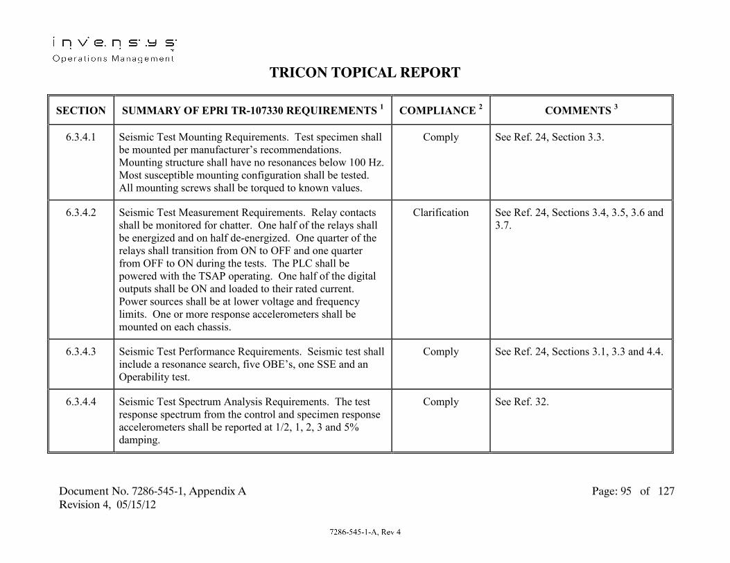
TRICON TOPICAL REPORT
Document No. 7286-545-1, Appendix A Page: 95 of 127 Revision 4, 05/15/12
SECTION SUMMARY OF EPRI TR-107330 REQUIREMENTS 1 COMPLIANCE 2 COMMENTS 3
6.3.4.1 Seismic Test Mounting Requirements. Test specimen shall be mounted per manufacturer’s recommendations. Mounting structure shall have no resonances below 100 Hz. Most susceptible mounting configuration shall be tested. All mounting screws shall be torqued to known values.
Comply See Ref. 24, Section 3.3.
6.3.4.2 Seismic Test Measurement Requirements. Relay contacts shall be monitored for chatter. One half of the relays shall be energized and on half de-energized. One quarter of the relays shall transition from ON to OFF and one quarter from OFF to ON during the tests. The PLC shall be powered with the TSAP operating. One half of the digital outputs shall be ON and loaded to their rated current. Power sources shall be at lower voltage and frequency limits. One or more response accelerometers shall be mounted on each chassis.
Clarification See Ref. 24, Sections 3.4, 3.5, 3.6 and 3.7.
6.3.4.3 Seismic Test Performance Requirements. Seismic test shall include a resonance search, five OBE’s, one SSE and an Operability test.
Comply See Ref. 24, Sections 3.1, 3.3 and 4.4.
6.3.4.4 Seismic Test Spectrum Analysis Requirements. The test response spectrum from the control and specimen response accelerometers shall be reported at 1/2, 1, 2, 3 and 5% damping.
Comply See Ref. 32.

TRICON TOPICAL REPORT
Document No. 7286-545-1, Appendix A Page: 96 of 127 Revision 4, 05/15/12
SECTION SUMMARY OF EPRI TR-107330 REQUIREMENTS 1 COMPLIANCE 2 COMMENTS 3
6.3.5 Surge Withstand Capability Testing. Surge testing shall be conducted per Section 4.6.2 and IEEE C62.45.
Comply See Table Section 4.6.2.
6.3.5.1 Surge Withstand Test Mounting Requirements. Test specimen shall be mounted on a non-metallic surface six feet above floor with no secondary enclosure. PLC shall be grounded per manufacturer’s recommendations.
Exception See Ref. 27. Due to space limitations of NTS Labs EMI/RFI chamber, the test test specimen was mounted less than six feet above floor. Test specimen was mounted in a Rittal cabinet with the sides and doors removed.
6.3.6 Class 1E to Non-1E Isolation Testing. Test specimen shall be mounted on a non-metallic surface six feet above floor with no secondary enclosure. PLC shall be grounded per manufacturer’s recommendations.
Exception See Ref. 29. Due to space limitations of NTS Labs EMI/RFI chamber, the test specimen was mounted less than six feet above floor. Test specimen was mounted in a Rittal cabinet with the sides and doors removed.
6.4 Other Tests and Analysis. (section heading) - - - No requirements.
6.4.1 FMEA. An FMEA analysis of the PLC shall be performed. Comply See Ref. 10.

TRICON TOPICAL REPORT
Document No. 7286-545-1, Appendix A Page: 97 of 127 Revision 4, 05/15/12
SECTION SUMMARY OF EPRI TR-107330 REQUIREMENTS 1 COMPLIANCE 2 COMMENTS 3
6.4.2
Electrostatic Discharge (ESD) Testing Requirements. ESD testing of the PLC shall be performed per EPRI TR-102323.
Comply See Ref 40, Section 7.0.
6.4.3 Power Quality Tolerance Requirements. Power quality tolerance testing shall be performed during acceptance testing, at the end of the elevated temperature test while still at high temperature and following seismic tests. The same AC source shall be connected to redundant power supplies during testing.
Comply See Ref. 20, Section 10.
6.4.4 Requirements for Compliance to Specifications. Test instrumentation measurement accuracy shall be considered. Compliance to specifications shall be considered for each module or grouping of modules.
Comply Where required, data analyses have been performed to provide for correction of the measured test data prior to comparison to acceptance criteria to account for the accuracies of the instruments used during testing. See Ref. 53
6.4.4.A Environmental Test Compliance. Environmental Operability test results shall be evaluated for compliance to specifications.
Comply See Ref. 35 and 52.

TRICON TOPICAL REPORT
Document No. 7286-545-1, Appendix A Page: 98 of 127 Revision 4, 05/15/12
SECTION SUMMARY OF EPRI TR-107330 REQUIREMENTS 1 COMPLIANCE 2 COMMENTS 3
6.4.4.B Seismic Test Compliance. The seismic levels achieved during testing shall be used as the seismic withstand response spectrum.
Comply See Ref. 36 and 52
6.4.4.C Class 1E to Non-1E Test Compliance. Test levels shall be checked for compliance to Section 4.6.4 specifications.
Comply See Ref. 41 and 52
6.4.4.D Surge Withstand Test Compliance. Test levels shall be checked for compliance to Section 4.6.2 specifications.
Comply See Ref. 39 and 52
6.4.4.E EMI/RFI Test Compliance. PLC performance shall be checked for compliance to Section 4.3.7 specifications.
Comply See Ref. 37 and 52
6.4.4.F Power Quality Test Compliance. Results shall be evaluated for compliance to Sections 4.6.1 and 4.2.3.7 specifications.
Comply See Ref. 52.
6.4.4.G ASOA Test Compliance. Results shall be evaluated for compliance to Section 5.6 requirements.
Exception See Ref. 2, Section 5. ASOA testing not performed.

TRICON TOPICAL REPORT
Document No. 7286-545-1, Appendix A Page: 99 of 127 Revision 4, 05/15/12
SECTION SUMMARY OF EPRI TR-107330 REQUIREMENTS 1 COMPLIANCE 2 COMMENTS 3
6.4.4.H Quality Assurance Program Compliance. Results of audits of manufacturer’s QA Program shall be checked for compliance to Section 7 requirements.
Comply Triconex is a 10CFR50, Appendix B supplier. The manufacturing and qualification processes are owned and controlled by Triconex. MPR was contracted by Triconex to perform some of the qualification tests. An audit of MPR was performed by Triconex. See Audit Report V0510.
6.4.5
Human Factors. Descriptive Information. - - - No requirements.
6.5 Quality Assurance Measures Applied to Qualification Testing. Test program TSAP development, hardware procurement, test specimen chain of custody, and tests and data analysis shall meet the requirements of 10CFR50, Appendix B.
Comply See Ref. 2, 4 and 5.
7 Quality Assurance. Descriptive information. - - - No requirements.
7.1 QA Overview. Descriptive information. - - - No requirements.
7.2 10CFR50 Appendix B Requirements for Safety-Related Systems. Descriptive information.
- - - No requirements.

TRICON TOPICAL REPORT
Document No. 7286-545-1, Appendix A Page: 100 of 127 Revision 4, 05/15/12
SECTION SUMMARY OF EPRI TR-107330 REQUIREMENTS 1 COMPLIANCE 2 COMMENTS 3
7.2.A 10CFR50 Applicability. Regulations apply to all qualification activities.
Comply See Ref. 4, Section 3.
7.2.B 10CFR50 Applicability. Regulations apply to application specific activities.
N/A Requirement applies to safety-related application of a PLC.
7.2.C
10CFR50 Applicability. Regulations apply to PLC dedication activities.
N/A Tricon PLC is manufactured under a 10CFR50 Appendix B program. Requirement applies to dedication of a commercial PLC.
7.2.D 10CFR50 Compliance. Quality processes other than 10CFR50 shall be shown to be commensurate with 10CFR50.
N/A Tricon PLC is manufactured under a 10CFR50 Appendix B program.
7.2.E 10CFR50 Compliance. Qualifier shall perform audits to confirm that manufacturer’s quality process has been applied to the PLC product.
Comply Triconex is a 10CFR50, Appendix B supplier. The manufacturing and qualification processes are owned and controlled by Triconex. MPR was contracted by Triconex to perform some of the qualification tests. An audit of MPR was performed by Triconex. See Audit Report V0510.

TRICON TOPICAL REPORT
Document No. 7286-545-1, Appendix A Page: 101 of 127 Revision 4, 05/15/12
SECTION SUMMARY OF EPRI TR-107330 REQUIREMENTS 1 COMPLIANCE 2 COMMENTS 3
7.2.F 10CFR50 Compliance. Audits performed against programs other than 10CFR50 shall demonstrate that the program process is commensurate with 10CFR50.
N/A Tricon PLC is manufactured under a 10CFR50 program.
7.2.G
V&V Program Evaluation. Qualifier shall evaluate the manufacturer’s V&V program to the criteria in Section 7.4.
Comply Triconex is a 10CFR50, Appendix B supplier. The manufacturing and qualification processes are owned and controlled by Triconex. V&V activities are performed by Triconex Engineering.
7.2.H Qualification Test Witnessing. The qualifier shall have the right to witness qualification tests.
Comply See Ref. 4 and 2. A Triconex Project Quality Assurance Engineer was permanently assigned to the qualification project. See the NQQP and Master Test Plan for PQAE responsibilities.
7.3 10CFR21 Compliance Requirements. Section lists 10CFR21 compliance requirements of a utility which applies the PLC in a safety-related application. PLC manufacturer shall support problem reporting and tracking.
N/A
Comply
Requirement applies to safety-related application of a PLC. See Table Section 7.8.
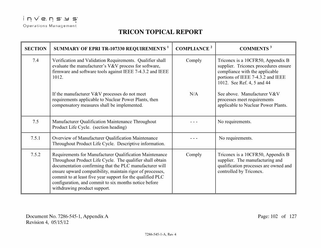
TRICON TOPICAL REPORT
Document No. 7286-545-1, Appendix A Page: 102 of 127 Revision 4, 05/15/12
SECTION SUMMARY OF EPRI TR-107330 REQUIREMENTS 1 COMPLIANCE 2 COMMENTS 3
7.4
Verification and Validation Requirements. Qualifier shall evaluate the manufacturer’s V&V process for software, firmware and software tools against IEEE 7-4.3.2 and IEEE 1012. If the manufacturer V&V processes do not meet requirements applicable to Nuclear Power Plants, then compensatory measures shall be implemented.
Comply
N/A
Triconex is a 10CFR50, Appendix B supplier. Triconex procedures ensure compliance with the applicable portions of IEEE 7-4.3.2 and IEEE 1012. See Ref. 4, 5 and 44 See above. Manufacturer V&V processes meet requirements applicable to Nuclear Power Plants.
7.5 Manufacturer Qualification Maintenance Throughout Product Life Cycle. (section heading)
- - - No requirements.
7.5.1 Overview of Manufacturer Qualification Maintenance Throughout Product Life Cycle. Descriptive information.
- - - No requirements.
7.5.2 Requirements for Manufacturer Qualification Maintenance Throughout Product Life Cycle. The qualifier shall obtain documentation confirming that the PLC manufacturer will ensure upward compatibility, maintain rigor of processes, commit to at least five year support for the qualified PLC configuration, and commit to six months notice before withdrawing product support.
Comply Triconex is a 10CFR50, Appendix B supplier. The manufacturing and qualification processes are owned and controlled by Triconex.

TRICON TOPICAL REPORT
Document No. 7286-545-1, Appendix A Page: 103 of 127 Revision 4, 05/15/12
SECTION SUMMARY OF EPRI TR-107330 REQUIREMENTS 1 COMPLIANCE 2 COMMENTS 3
7.5.3 Life Cycle Support for Tools Requirement. PLC manufacturer shall ensure continued access to the same versions of application software development tools, or capability to reconstruct functionality with using revised tools.
Comply See Ref. 5.
7.6 Compensatory Quality Activities for Legacy Software. (section heading)
- - - No requirements.
7.6.1 Overview of Compensatory Quality Activities for Legacy Software. Descriptive information.
- - - No requirements.
7.6.2 Requirements for Compensatory Quality Activities for Legacy Software. The qualifier may compensate for shortcomings in legacy software by evaluating documented operating experience in applications similar to nuclear safety related applications, and by performing tests of legacy software to confirm conformance to requirements. The manufacturer shall place legacy software under configuration control once baselined.
N/A See Ref. 58. No legacy software is included in the qualification project scope.
7.7 Configuration Management. (section heading) - - - No requirements.
7.7.1 Configuration Management Overview. Descriptive information.
- - - No requirements.

TRICON TOPICAL REPORT
Document No. 7286-545-1, Appendix A Page: 104 of 127 Revision 4, 05/15/12
SECTION SUMMARY OF EPRI TR-107330 REQUIREMENTS 1 COMPLIANCE 2 COMMENTS 3
7.7.2 Hardware Configuration Management Requirements. The scope shall include revisions to module design, module component configuration, compatibility of revised modules with existing hardware, and manufacturer documentation.
Comply See Ref. 5.
7.7.2.A
Hardware Configuration Management Review. Utility (and Qualifier) shall evaluate the manufacturer configuration management process for design revisions to NQA-1.
Comply See Ref. 58. Configuration management reviews considered both hardware and software.
7.7.2.B Hardware Configuration Management Review. Utility (and Qualifier) shall evaluate the manufacturer configuration management process for methods of identification of each constituent component within the PLC modules to NQA-1.
Comply See Ref. 58. Configuration management reviews considered both hardware and software.
7.7.2.C Hardware Configuration Management Review. Utility (and Qualifier) shall evaluate the manufacturer configuration management process for methods of document control to NQA-1.
Comply See Ref. 58. Configuration management reviews considered both hardware and software.
7.7.3 Software Configuration Management Requirements. The scope of software configuration management includes creation and revision of firmware, runtime software libraries, software engineering tools, and documentation.
Comply See Ref. 5.

TRICON TOPICAL REPORT
Document No. 7286-545-1, Appendix A Page: 105 of 127 Revision 4, 05/15/12
SECTION SUMMARY OF EPRI TR-107330 REQUIREMENTS 1 COMPLIANCE 2 COMMENTS 3
7.7.3.A
Software Configuration Management Review. Utility (and Qualifier) shall evaluate the manufacturer software configuration management process for definition of organization and responsibilities to Reg. Guide 1.169, Section C.
Comply See Ref. 58.
7.7.3.B Software Configuration Management Review. Utility (and Qualifier) shall evaluate the manufacturer software configuration management process for methods of configuration identification, control, status and audits to Reg. Guide 1.169, Section C.
Comply See Ref. 52.

TRICON TOPICAL REPORT
Document No. 7286-545-1, Appendix A Page: 106 of 127 Revision 4, 05/15/12
SECTION SUMMARY OF EPRI TR-107330 REQUIREMENTS 1 COMPLIANCE 2 COMMENTS 3
7.7.3.C
Software Configuration Management Review. Utility (and Qualifier) shall evaluate the manufacturer configuration management process to ensure sub-tier suppliers maintain comparable levels of configuration management per Reg. Guide 1.169, Section C.
Comply See Ref. 58.

TRICON TOPICAL REPORT
Document No. 7286-545-1, Appendix A Page: 107 of 127 Revision 4, 05/15/12
SECTION SUMMARY OF EPRI TR-107330 REQUIREMENTS 1 COMPLIANCE 2 COMMENTS 3
7.8 Problem Reporting/Tracking Requirements. PLC manufacturer shall maintain a problem reporting and tracking system that includes classification of problems, description of problems, identification of affected hardware, type of application, description of configuration, name of reporting site and means to contact site, type of site, and cumulative operating time of PLC when problem occurred. Manufacturer shall provide a mechanism for making this information available to all nuclear utility users.
Comply Key Procedures: - QAM 14.0: Corrective Action - QAM 19.0: Servicing - QAM 13.3: 10CFR21 Reporting - QPM 14.0: QA Review Board - QPM 14.1: Customer Contacts - QPM 13.2: Product Discrepancies. - QPM 19.1 to 6: RMA Process Key Documents: - Product Discrepancy Reports - Customer Service Database - Customer System Config. Files - Product Alert Notices
8 Documentation. Descriptive information. - - - No requirements.
8.1 Equipment General Overview Document Requirements. Descriptive information.
- - - No requirements.
8.1.A Manufacturer Documentation. Documentation shall include a description of the PLC.
Comply See Ref. 45, Chapter 1, 2, 3 and 4, Ref. 48, 49, and 50.
8.1.B Manufacturer Documentation. Documentation shall include a description of the chassis interconnections.
Comply See Ref. 45, Chapter 3.

TRICON TOPICAL REPORT
Document No. 7286-545-1, Appendix A Page: 108 of 127 Revision 4, 05/15/12
SECTION SUMMARY OF EPRI TR-107330 REQUIREMENTS 1 COMPLIANCE 2 COMMENTS 3
8.1.C Manufacturer Documentation. Documentation shall include a module overview and selection guide.
Comply See Ref. 45, Chapter 2.
8.1.D Manufacturer Documentation. Documentation shall include a description of the overall I/O capacity and processing speeds.
Comply See Ref. 45, Chapter 2.
8.1.E Manufacturer Documentation. Documentation shall include installation information.
Comply See Ref. 45, Chapter 3, Ref. 48 and 14.
8.1.F Manufacturer Documentation. Documentation shall include handling and storage requirements.
Comply See Ref. 45, Chapter 3.
8.1.G Manufacturer Documentation. Documentation shall include a description of the self-diagnostics and redundancy features.
Comply See Ref. 45, Chapter 2.
8.2 Equipment General Specifications Requirements. Manufacturer documentation shall provide general specifications for the PLC.
Comply See Ref. 45 and 49.
8.3 Operator’s Manual Requirements. Manufacturer documentation shall include information on operation of the PLC.
Comply See Ref. 45 and 49.

TRICON TOPICAL REPORT
Document No. 7286-545-1, Appendix A Page: 109 of 127 Revision 4, 05/15/12
SECTION SUMMARY OF EPRI TR-107330 REQUIREMENTS 1 COMPLIANCE 2 COMMENTS 3
8.4 Programmer’s Manual Requirements. Manufacturer shall provide detailed information on the use of the functions available in the PLC processors.
Comply See Ref. 46 and 47.
8.4.A Programmer’s Manual Requirements. Manual shall include a summary and brief description of available functions.
Comply See Ref. 46 and 47
8.4.B Programmer’s Manual Requirements. Manual shall include a detailed description of each function.
Comply See Ref. 46 and 47
8.4.C Programmer’s Manual Requirements. Manual shall include examples of complex functions.
Comply See Ref. 46, Section 2.
8.4.D Programmer’s Manual Requirements. Manual shall include limitations on use of functions.
Comply See Ref. 46 and 47
8.4.E Programmer’s Manual Requirements. Manual shall include methods for resource management.
Comply See Ref. 46 and 47
8.4.F Programmer’s Manual Requirements. Manual shall include a user manual for programming and debugging tools, and for any programming terminal.
Comply See Ref. 46 and 47
8.4.G Programmer’s Manual Requirements. Manual shall include detailed information for creating user defined functions.
Comply See Ref. 46 and 47

TRICON TOPICAL REPORT
Document No. 7286-545-1, Appendix A Page: 110 of 127 Revision 4, 05/15/12
SECTION SUMMARY OF EPRI TR-107330 REQUIREMENTS 1 COMPLIANCE 2 COMMENTS 3
8.4.H Programmer’s Manual Requirements. Manual shall include a detailed description of operation of conditional statements.
Comply See Ref. 46 and 47
8.4.I Programmer’s Manual Requirements. Manual shall include a description of limitations of PID and lead/lag functions.
Comply See Ref. 46 and 47
8.4.J Programmer’s Manual Requirements. Manual shall include a description of interaction between main processor and I/O modules.
Comply See Ref. 46 and 47
8.4.K Programmer’s Manual Requirements. Manual shall include a detailed description of interaction between the application program and redundancy features.
Comply See Ref. 47.
8.4.L Programmer’s Manual Requirements. Manual shall include any software build procedures and software tools.
Comply See Ref. 46 and 47
8.4.M Programmer’s Manual Requirements. Manual shall include a description of the operation of the executive.
Comply See Ref. 46 and 47
8.4.N Programmer’s Manual Requirements. Manual shall include a description of data, data base and configuration management.
Comply See Ref. 46 and 47

TRICON TOPICAL REPORT
Document No. 7286-545-1, Appendix A Page: 111 of 127 Revision 4, 05/15/12
SECTION SUMMARY OF EPRI TR-107330 REQUIREMENTS 1 COMPLIANCE 2 COMMENTS 3
8.4.O Programmer’s Manual Requirements. Manual shall include a description of operation and use of self-diagnostics.
Comply See Ref. 47.
8.4.P Programmer’s Manual Requirements. Manual shall include a manual for coprocessor programming.
N/A Coprocessor operation is invoked automatically.
8.5 Equipment Maintenance Manual Requirements. Manufacturer documentation shall contain information for calibration, trouble shooting, maintenance, required special tools or software, and communication protocols. Manufacturer documentation shall include results of component aging analysis.
Comply
Comply
See Ref. 45, Chapter 4, and Ref. 50 See this report, Section 2.2.15.
8.6 Qualification Documentation Requirements. Qualifier shall provide and submit all qualification documentation to customer utility for review and approval.
Comply See Ref. 3.
8.6.1
Programmatic Documentation Requirements. Descriptive information.
- - - No requirements.

TRICON TOPICAL REPORT
Document No. 7286-545-1, Appendix A Page: 112 of 127 Revision 4, 05/15/12
SECTION SUMMARY OF EPRI TR-107330 REQUIREMENTS 1 COMPLIANCE 2 COMMENTS 3
8.6.1.A Programmatic Documentation. A test plan shall be prepared which includes test plans for environmental, seismic, surge, Class 1E to Non-1E, EMI/RFI, availability/reliability, FMEA and ASOA qualification activities.
Comply See Ref. 1 and 2.
8.6.1.B Programmatic Documentation. Test specifications shall be prepared which include equipment identifications, interfaces and service conditions.
Comply See Ref. 2 and 3.
8.6.1.C Programmatic Documentation. Procedures shall be prepared for qualification testing.
Comply See Ref. 2, 19, 20, 21, 22, 23, 24, 25, 26, 27, 28 29, and 65.
8.6.1.D Programmatic Documentation. Test reports shall be prepared for each qualification test performed.
Comply See Ref., 34, 35, 36, 37, 38, 39, 40 41, 53, 64, 66, 67 and 68.
8.6.1.E Programmatic Documentation. Reports on audits performed on the manufacturer shall be prepared.
Comply Triconex is a 10CFR50, Appendix B supplier. The manufacturing and qualification processes are owned and controlled by Triconex. MPR was contracted by Triconex to perform some of the qualification tests. An audit of MPR was performed by Triconex. See Audit Report V0510.
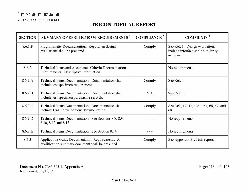
TRICON TOPICAL REPORT
Document No. 7286-545-1, Appendix A Page: 113 of 127 Revision 4, 05/15/12
SECTION SUMMARY OF EPRI TR-107330 REQUIREMENTS 1 COMPLIANCE 2 COMMENTS 3
8.6.1.F
Programmatic Documentation. Reports on design evaluations shall be prepared.
Comply See Ref. 8. Design evaluations include interface cable similarity analysis.
8.6.2 Technical Items and Acceptance Criteria Documentation Requirements. Descriptive information.
- - - No requirements.
8.6.2.A Technical Items Documentation. Documentation shall include test specimen requirements.
Comply See Ref. 1.
8.6.2.B Technical Items Documentation. Documentation shall include test specimen purchasing records.
N/A See Ref. 3 .
8.6.2.C Technical Items Documentation. Documentation shall include TSAP development documentation.
Comply See Ref., 17, 18, 4344, 64, 66, 67, and 68.
8.6.2.D Technical Items Documentation. See Sections 8.8, 8.9, 8.10, 8.12 and 8.13.
- - - No requirements.
8.6.2.E Technical Items Documentation. See Section 8.14. - - - No requirements.
8.6.3 Application Guide Documentation Requirements. A qualification summary document shall be provided.
Comply See Appendix B of this report.

TRICON TOPICAL REPORT
Document No. 7286-545-1, Appendix A Page: 114 of 127 Revision 4, 05/15/12
SECTION SUMMARY OF EPRI TR-107330 REQUIREMENTS 1 COMPLIANCE 2 COMMENTS 3
8.6.3.A
Application Guide. Guide shall include results of environmental Operability testing to support each specific safety related application.
Comply See Ref. 35, 52, and 53, and Appendix B of this report.
8.6.3.B Application Guide. Guide shall include results of seismic testing including seismic withstand capability for all damping values used in test data analysis.
Comply See Ref. 36 and Appendix B of this report.
8.6.3.C Application Guide. Guide shall include results of Class 1E to Non-1E isolation testing.
Comply See Ref. 41 and Appendix B of this report.
8.6.3.D Application Guide. Guide shall include results of surge withstand testing.
Comply See Ref. 39 and 57, and Appendix B of this report.
8.6.3.E Application Guide. Guide shall include results of EMI/RFI testing.
Comply See Ref. 37 and 57, and Appendix B of this report.
8.6.3.F Application Guide. Guide shall include results of power quality testing.
Comply See Ref. 52 and Appendix B of this report.
8.6.3.G Application Guide. Guide shall describe any combination of software objects or special purpose objects created to support testing.
N/A No software objects or special purpose objects were used in testing.

TRICON TOPICAL REPORT
Document No. 7286-545-1, Appendix A Page: 115 of 127 Revision 4, 05/15/12
SECTION SUMMARY OF EPRI TR-107330 REQUIREMENTS 1 COMPLIANCE 2 COMMENTS 3
8.6.3.H
Application Guide. Guide shall include a description of the as-tested PLC configuration.
Comply Appendix B of this report.
8.6.3.I Application Guide. Guide shall include a description of the executive software and software tools revision levels included in qualification.
Comply See Ref. 3 and Appendix B of this report.
8.6.3.J Application Guide. Guide shall include a description of the as-tested PLC configuration.
Comply See Ref. 42 and Appendix B of this report.
8.6.3.K Application Guide. Guide shall include a summary of the FMEA and availability analysis.
Comply See Ref. 9, 10 and Appendix B of this report.
8.6.3.L Application Guide. Guide shall include the setpoint analysis support document.
Comply See Ref. 9 and Appendix B of this report.
8.6.3.M Application Guide. Guide shall include information from manufacturer audits and surveys applicable to future purchasing.
Comply See Appendix B of this report.
8.6.3.N Application Guide. Guide shall include a description of the redundancy features include in qualification.
Comply See Appendix B of this report.

TRICON TOPICAL REPORT
Document No. 7286-545-1, Appendix A Page: 116 of 127 Revision 4, 05/15/12
SECTION SUMMARY OF EPRI TR-107330 REQUIREMENTS 1 COMPLIANCE 2 COMMENTS 3
8.6.3.O Application Guide. Guide shall include a description of external devices included in qualification.
Comply See Appendix B of this report.
8.6.3.P Application Guide. Guide shall include a description of the PLC configuration management methods.
Comply See Appendix B of this report.
8.6.3.Q Application Guide. Guide shall include a summary of the component aging analysis.
Comply See Appendix B of this report.
8.6.3.R Application Guide. Guide shall include a description of seismic mounting methods.
Comply See Ref. 14 and Appendix B of this report.
8.6.3.S Application Guide. Guide shall include a description of qualification envelopes for specific modules if different from the overall envelope.
Comply Appendix B of this report.
8.6.3.T Application Guide. Guide shall include a description of any application hardware or software features that are assumed in order to meet qualification requirements.
Comply See Appendix B of this report.
8.6.4 Supporting Analyses Documentation Requirements. Documentation shall be provided of the FMEA and Availability/Reliability Analyses.
Comply See Ref. 10 and 11.

TRICON TOPICAL REPORT
Document No. 7286-545-1, Appendix A Page: 117 of 127 Revision 4, 05/15/12
SECTION SUMMARY OF EPRI TR-107330 REQUIREMENTS 1 COMPLIANCE 2 COMMENTS 3
8.6.5 Class 1E to Non-1E Isolation Test Plan. A Class 1E to Non-1E Isolation test plan and report shall be provided. The test plan shall be reviewed and approved by the utility.
Comply See Ref. 2, 29 and 41.
8.7 V&V Documentation Requirements. Descriptive information.
- - - No requirements.
8.7.A V&V Documentation. Documentation shall include a software quality assurance plan.
Comply See Ref. 5.
8.7.B V&V Documentation. Documentation shall include a software requirements specification.
Comply See Ref. 17.
8.7.C V&V Documentation. Documentation shall include a software design description.
Comply See Ref. 18.
8.7.D V&V Documentation. Documentation shall include a software V&V plan.
Comply See Ref. 5.
8.7.E V&V Documentation. Documentation shall include a software V&V report.
Comply See Ref. 44.
8.7.F V&V Documentation. Documentation shall include software user documentation.
Comply See Ref. 46.

TRICON TOPICAL REPORT
Document No. 7286-545-1, Appendix A Page: 118 of 127 Revision 4, 05/15/12
SECTION SUMMARY OF EPRI TR-107330 REQUIREMENTS 1 COMPLIANCE 2 COMMENTS 3
8.7.G V&V Documentation. Documentation shall include a software configuration management plan.
Comply See Ref. 5.
8.8
System Description Requirements. A test specimen hardware and software description document shall be provided.
Comply See Ref. 42.
8.9 Critical Characteristics Listing Requirement. A critical characteristics listing document shall be provided.
N/A Triconex is a 10CFR50, Appendix B supplier. Commercial dedication of Tricon PLC is not required.
8.10 System Drawing Requirements. A set of test specimen hardware, software and configuration drawings shall be provided.
Comply See Ref. 14.
8.10.A System Drawing Requirements. Drawings shall include a functional description of the test specimen.
Comply See Ref. 15, Functional Drawings.
8.10.B System Drawing Requirements. Drawings shall include a schematic of the test specimen.
Comply See Ref. 12 and 14, Wiring Schedule and System Drawings.
8.10.C System Drawing Requirements. Drawings shall include diagrams that define the TSAP.
Comply See Ref. 15, Functional Diagrams.

TRICON TOPICAL REPORT
Document No. 7286-545-1, Appendix A Page: 119 of 127 Revision 4, 05/15/12
SECTION SUMMARY OF EPRI TR-107330 REQUIREMENTS 1 COMPLIANCE 2 COMMENTS 3
8.10.D System Drawing Requirements. Drawings shall show test specimen wiring, power distribution and grounding.
Comply See Ref. 12 and 14, Wiring Schedule and System Drawings.
8.10.E
System Drawing Requirements. Drawings shall show layout of test specimen chassis, modules and qualification test fixtures.
Comply See Ref. 12 and 14, Wiring Schedule and System Drawings.
8.10.F System Drawing Requirements. Drawings shall show test specimen mounting and mounting fixtures, including special installation requirements.
Comply See Ref. 12 and 14, Wiring Schedule and System Drawings.
8.11 System Software/Hardware Configuration Document Requirements. Software and hardware configuration used for qualification testing shall be documented, including identification and revision of executive software, module firmware, software tools, downloadable PLC executive packages, and the TSAP (including printout). The identification, revision level and serial number of hardware shall be documented.
Comply See Ref. 3.
8.12 System Database Documentation Requirements. The TSAP database used for qualification testing shall be documented.
Comply See Ref. 15, and 18.

TRICON TOPICAL REPORT
Document No. 7286-545-1, Appendix A Page: 120 of 127 Revision 4, 05/15/12
SECTION SUMMARY OF EPRI TR-107330 REQUIREMENTS 1 COMPLIANCE 2 COMMENTS 3
8.13
System Setup/Calibration/Checkout Procedure Requirements. All setup, calibration and checkout procedures used during qualification shall be documented.
Comply See Ref. 19.
8.14 System Test Documentation Requirements. A test plan and test report shall be provided covering qualification Operability testing. The documents shall include test requirements, acceptance criteria, sequence of testing, data recording methods, test equipment requirements and a test data summary.
Comply See Ref. 2, 20 and 53.
8.15 Manufacturer’s Quality Documentation Requirements. The manufacturer shall provide its Quality Assurance Plan.
Comply See Ref. 4 and 5.
8.16 Manufacturer’s Certifications Requirements. Manufacturer shall provide certificates of conformance for all test specimen hardware.
Comply See Ref. 56.
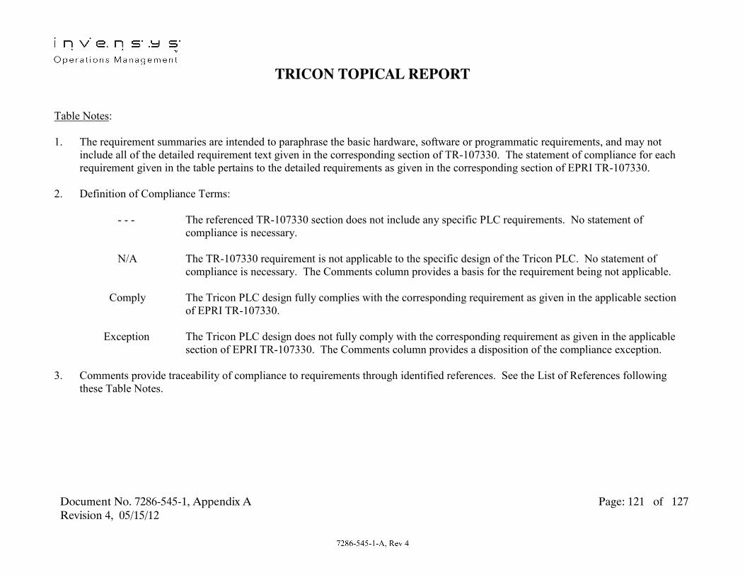
TRICON TOPICAL REPORT
Document No. 7286-545-1, Appendix A Page: 121 of 127 Revision 4, 05/15/12
Table Notes
:
1. The requirement summaries are intended to paraphrase the basic hardware, software or programmatic requirements, and may not include all of the detailed requirement text given in the corresponding section of TR-107330. The statement of compliance for each requirement given in the table pertains to the detailed requirements as given in the corresponding section of EPRI TR-107330.
2. Definition of Compliance Terms:
- - - The referenced TR-107330 section does not include any specific PLC requirements. No statement of compliance is necessary.
N/A The TR-107330 requirement is not applicable to the specific design of the Tricon PLC. No statement of
compliance is necessary. The Comments column provides a basis for the requirement being not applicable. Comply The Tricon PLC design fully complies with the corresponding requirement as given in the applicable section
of EPRI TR-107330. Exception The Tricon PLC design does not fully comply with the corresponding requirement as given in the applicable
section of EPRI TR-107330. The Comments column provides a disposition of the compliance exception.
3. Comments provide traceability of compliance to requirements through identified references. See the List of References following these Table Notes.

TRICON TOPICAL REPORT
Document No. 7286-545-1, Appendix A Page: 122 of 127 Revision 4, 05/15/12
List of References
:
Note: Unless indicated, applicable revision levels of all Triconex documents, reports, procedures and drawings were per the current revision of Triconex Document No. 9600164-540, Master Configuration List upon completion of the Nuclear Qualification Project. Subsequent revisions are maintained in the Triconex R&D Engineering database (Agile).
1. EPRI Technical Report TR-107330, Final Report dated December, 1996, Generic Requirements Specification for Qualifying
a Commercially Available PLC for Safety-Related Applications in Nuclear Power Plants. 2. Triconex Document No. 9600164-500, Tricon Nuclear Qualification Program Master Test Plan (MTP).
3. Triconex Document No. 9600164-540, Tricon Nuclear Qualification Program Master Configuration List (MCL).
4. Triconex Document No. 9600164-002, Tricon Nuclear Qualification Quality Plan (NQQP)
5. Triconex Document No. 9600164-537, Tricon Nuclear Qualification Program Software Quality Assurance Plan (SQAP).
6. Triconex Document No. 9600164-730, Analog Input/Output Machine Count Calculations.
7. Triconex Document No. 9600164-731, Maximum Response Time Calculations.
8. Triconex Document No. 9600164-538, External Termination Panel Interface Cable Similarity Analysis.
9. Triconex Document No. 9600164-534, Tricon System Accuracy Specifications.
10. Triconex Document No. 9600164-531, Failure Modes and Effects Analysis.

TRICON TOPICAL REPORT
Document No. 7286-545-1, Appendix A Page: 123 of 127 Revision 4, 05/15/12
11. Triconex Document No. 9600164-532, Reliability/Availability Study.
12. Triconex Document No. 9600164-700, Wiring Schedule. 13. Triconex Drawing No. 9600164-100 to 103 & 9600164-105, System Drawings. 14. Triconex Drawing No. 9600164-200 to 207, System Drawings. 15. Triconex Drawing No. 9600164-600 to 614, Function Diagrams. 16. Triconex Document No. 9600121-001, Tricon System Test Requirements Specification. 17. Triconex Document No. 9600164-517, TSAP Software Requirements Specification. 18. Triconex Document No. 9600164-518, TSAP Software Design Description. 19. Triconex Document No. 9600164-502, System Setup & Checkout Procedure. 20. Triconex Document No. 9600164-503, Operability Test Procedure. 21. Triconex Document No. 9600164-504, Prudency Test Procedure. 22. Triconex Document No. 9600164-506, Environmental Test Procedure. 23. Triconex Document No. 9600164-511, Radiation Exposure Test Procedure. 24. Triconex Document No. 9600164-507, Seismic Test Procedure.

TRICON TOPICAL REPORT
Document No. 7286-545-1, Appendix A Page: 124 of 127 Revision 4, 05/15/12
25. Triconex Document No. 9600164-510, EMI/RFI Test Procedure. 26. Triconex Document No. 9600164-514, EFT Test Procedure. 27. Triconex Document No. 9600164-508, Surge Withstand Test Procedure. 28. Triconex Document No. 9600164-512, ESD Test Procedure. 29. Triconex Document No. 9600164-509, Class 1E Isolation Test Procedure. 30. NTS Document No. TP62987-07N-ENV, Procedure for Environmental Qualification. 31. NTS Document No. TP62987-07N-RAD, Procedure for Radiation Testing. 32. NTS Document No. TP62987-07N-SEI, Procedure for Seismic Qualification.
33. NTS Document No. TP62987-07N-EMI, Procedure for EMI Qualification. 34. Triconex Document No. 9600164-512, Tricon Nuclear Qualification Program Radiation Exposure Test Report. 35. Triconex Document No. 9600164-525, Tricon Nuclear Qualification Program Environmental Test Report. 36. Triconex Document No. 9600164-526, Tricon Nuclear Qualification Program Seismic Test Report. 37. Triconex Document No. 9600164-527, Tricon Nuclear Qualification Program EMI/RFI Test Report.

TRICON TOPICAL REPORT
Document No. 7286-545-1, Appendix A Page: 125 of 127 Revision 4, 05/15/12
38. Triconex Document No. 9600164-521, Tricon Nuclear Qualification Program EFT Test Report. 39. Triconex Document No. 9600164-528, Tricon Nuclear Qualification Program Surge Withstand Test Report. 40. Triconex Document No. 9600164-522, Tricon Nuclear Qualification Program ESD Test Report. 41. Triconex Document No. 9600164-529, Tricon Nuclear Qualification Program Class 1E to Non 1E Isolation Test Report.
42. Triconex Document No. 9600164-541, Tricon Nuclear Qualification Program System Description. 43. Triconex Document No. 9600164-513, TSAP Software Verification and Validation Plan. 44. Triconex Document No. 9600164-536, TSAP Final V&V Report.
45. Planning and Installation Guide for Tricon v9-v10 Systems, Part No. 9700077-002.
46. Tristation 1131 Developer’s Workbench, Document No. 9700100-003.
47. Tristation 1131 Developer’s Workbench Libraries Reference, TS 1131 Version 4.1, Document No. 9700098-003.
48. Tricon Version 9-10 Systems Field Termination Guide, Part No. 9700052-012.
49. Tricon Version 9-10 System Technical Product Guide, Part No. 9791007-013.
50. Tricon Version 9-10 System Communication Guide, Part No. 9700088-001.
51. Tricon V9-10 System, Safety Consideration Guide, Part No. 9700097-001.

TRICON TOPICAL REPORT
Document No. 7286-545-1, Appendix A Page: 126 of 127 Revision 4, 05/15/12
52. Triconex Document No. 9600164-545, Equipment Qualification Summary Report.
53. Triconex Document No. 9600164-566, Performance Proof Operability Test Report.
54. Triconex Corporation, Quality Assurance Manual Date 06/07/2007.
55. . Triconex Part No. 1600083-200 document attachment, 7B34_analog.pdf.
56. Triconex Document No. 9600164-540, Master Configuration List.
57. USNRC Regulatory Guide 1.180, Revision 1 - Guidelines for Evaluating Electromagnetic and Radio-Frequency Interference
in Safety-Related Instrumentation and Control Systems.
58. Triconex Document No. 9600164-535, Software Qualification Report.
59. SOE Recorder User’s Guide, v4.0, Document Number 9720081-003.
60. Enhanced Diagnostics Monitor v2.0 User’s Guide, Document Number 9720107-002.
61. Triconex Document Number 9600164-538, External Termination Panel Interface Cable Assembly Similarity Analysis.
62. Triconex Corporation Quality Assurance Manual.
63. Triconex Engineering Procedure EDM 75.00, Nuclear Product Qualification.
64. Triconex Document No. 9600164-573, Performance Proof Prudency Test Report.

TRICON TOPICAL REPORT
Document No. 7286-545-1, Appendix A Page: 127 of 127 Revision 4, 05/15/12
65. Triconex Document No. 9600164-716, TSAP Software Validation Test Procedure.
66. Triconex Document No. 9600164-570, Pre-Qualification Prudency Test Report.
67. Triconex Document No. 9600164-713, V&V Test Phase Summary Report.
68. Triconex Document No. 9600164-717, Software Validation Test Report.

Triconex Approved Topical Report Document No.: 7286-545-1-A Revision: 4 Date: May 15, 2012
PART 6
Appendix B to Triconex Topical Report 7286-545-1 (Application Guide)

TRICONEX TOPICAL REPORT
APPLICATION GUIDE
Document No.: 7286-545-1
Revision 4
May 15, 2012
Appendix B

TRICON TOPICAL REPORT
TABLE OF CONTENTS
SECTION PAGE
Document No. 7286-545-1, Appendix B Page: 2 of 68 Revision 4, 05/15/12
1.0 INTRODUCTION............................................................................................................................. 4
2.0 SYSTEM CAPABILITIES ............................................................................................................... 5 2.1 The Tricon Programmable Logic Controller ........................................................................... 5 2.2 Key System Features ................................................................................................................ 5
3.0 SYSTEM DESIGN GUIDANCE ..................................................................................................... 8 3.1 Power ....................................................................................................................................... 8 3.2 Connection to Plant Instrumentation and Controls .................................................................. 9 3.3 Tricon Chassis Configuration ................................................................................................ 11 3.4 Tricon Communications Interfaces ........................................................................................ 12 3.5 Failure Analysis and SAR Chapter 15 ................................................................................... 14 3.6 Diversity and Defense-in-Depth ............................................................................................ 15 3.6.1 Licensing Criteria ................................................................................................................... 17 3.6.2 Defense-In-Depth and Diversity Requirements ..................................................................... 18 3.6.3 Diversity Implementation ...................................................................................................... 19 3.7 Setpoint Accuracy Calculations ............................................................................................. 23 3.8 Bypass and Indication ............................................................................................................ 28 3.9 Self-Test Capabilities ............................................................................................................. 28 3.10 Surveillance Capabilities ....................................................................................................... 30 3.11 Operational Constraints ......................................................................................................... 33 3.12 Error Reporting and Tracking ................................................................................................ 34
4.0 ENVIRONMENT AND LOCATION ............................................................................................ 35 4.1 Mounting ................................................................................................................................ 35 4.2 Temperature and Humidity .................................................................................................... 35 4.3 Heat Loads in Cabinets and Rooms ....................................................................................... 36 4.4 Seismic Acceleration Limits .................................................................................................. 36 4.5 Radiation Fields ..................................................................................................................... 39 4.6 EMI/RFI Compatibility .......................................................................................................... 39 4.7 Electrical Fast Transient Testing ........................................................................................... 46 4.8 Surge Withstand Testing ........................................................................................................ 47 4.9 Electrostatic Discharge (ESD) Testing .................................................................................. 48 4.10 Isolation Testing ..................................................................................................................... 48 4.11 Operability Testing ................................................................................................................ 49

TRICON TOPICAL REPORT
TABLE OF CONTENTS
SECTION PAGE
Document No. 7286-545-1, Appendix B Page: 3 of 68 Revision 4, 05/15/12
5.0 PROGRAMMING GUIDANCE .................................................................................................... 50 5.1 Cycle time .............................................................................................................................. 50 5.2 Software Quality Assurance Processes .................................................................................. 51 5.3 Guidance for Application Programming ................................................................................ 52 5.4 Loss of Power Fault Indication .............................................................................................. 56 5.5 Communication with External Systems ................................................................................. 58 5.6 Peer-to-Peer Communication ................................................................................................. 58 5.7 Communication Application Safety Layer ............................................................................. 60
6.0 INSTALLATION, COMMISSIONING, AND MAINTENANCE ................................................. 61 6.1 Required testing ..................................................................................................................... 61 6.2 Operations Procedures ........................................................................................................... 61 6.3 Maintenance Procedures ........................................................................................................ 62 6.4 Application Program Maintenance Procedures...................................................................... 63 6.5 Maintenance and Bypass Capabilities .................................................................................... 64
7.0 REFERENCES ............................................................................................................................... 67

TRICON TOPICAL REPORT
Document No. 7286-545-1, Appendix B Page: 4 of 68 Revision 4, 05/15/12
1.0 INTRODUCTION
This report provides guidelines and qualification limitations for applying the Triconex Tricon Programmable Logic Controller (PLC) in nuclear power plant systems classified as Safety Related and Important to Safety. The guidance provided in this document is intended to simplify use and application of the Tricon by consolidating design requirements, operational limitations, and other important data derived from the generic qualification program. Additional requirements and limitations may apply to a plant-specific application.
Some of the guidance provided in this document is not necessarily specific to the Tricon PLC or TriStation 1131 Developer’s Workstation. In these cases, the guidance provided is generic and should be applied to any installation involving digital equipment. Installation practices can create long term problems, which are often ascribed to software. Correct initial system installation will enhance reliable system operation. In that respect, the generic guidance provided should be considered appropriate for use with any PLC in a safety critical application.
Guidelines are provided for design, licensing, installation, operation, and maintenance of the system. Many of the guidelines in this document are interrelated. As an example, consider generation of fault alarms. The fault alarm has implications in design, operating and maintenance procedures, plant interface, main control room impacts, and several other seemingly unrelated topics, including system power supply. Therefore, the guidelines should be considered as a whole, rather than in separated, individual pieces.
In addition to the guidelines presented in this document, the standard manufacturer’s recommendations provided by Triconex for application of the Tricon should be followed. These are documented in the Triconex Planning and Installation Guide (Reference 7.13).

TRICON TOPICAL REPORT
Document No. 7286-545-1, Appendix B Page: 5 of 68 Revision 4, 05/15/12
2.0 SYSTEM CAPABILITIES
2.1 The Tricon Programmable Logic Controller
The Tricon Programmable Logic Controller (PLC) with the TriStation 1131 Development Workstation provides a suitable platform for implementation of safety-critical digital Instrumentation and Control systems. The Triple Modular Redundant design of the Tricon PLC has been shown to provide a high degree of reliability in addition to high availability. These characteristics make the Tricon platform particularly suited to nuclear safety-related applications. The TriStation 1131 Development Workstation, when used as described in this guide, provides a suitable means for developing and maintaining application software and configuring the Tricon system.
A detailed description of the Tricon PLC and TriStation 1131 is provided in Section 4.1 of the Qualification Summary Report (Reference 7.18).
Hardware type tests were performed with Version 10.2.1 of the Tricon system. However, the specific version of the Tricon system supplied for nuclear plant applications may be a later version. If versions later than Version 10.2.1 are supplied for nuclear safety-related applications, the qualification basis described in this report will be augmented with technical evaluations or additional testing based on the requirements established in Section 6.8 of IEEE Standard 323-1974.
2.2 Key System Features
This section provides an overview of the key features of the Tricon PLC.
The Tricon PLC is constructed of individual modules, installed in rack mount chassis. There are certain modules that are required, such as power supplies and Main Processors. The remaining modules, number of chassis required, and locations of the modules are configurable.
The Tricon PLC is designed as a Triple Modular Redundant (TMR) system and has been demonstrated to be resistant to single, active failure mechanisms. The power supplies are dual redundant, with each supply capable of providing all power requirements to the chassis in which it is installed. The backplane communication paths are triple redundant. The input and output modules are triple redundant internal

TRICON TOPICAL REPORT
Document No. 7286-545-1, Appendix B Page: 6 of 68 Revision 4, 05/15/12
to the module. Three separate Main Processor modules are required. Communication modules to external systems may be single train or dual redundant.
The Tricon PLC was designed as a single division Emergency Shutdown System or Safety Instrumentation System. Industries other than nuclear make use of only a single division safety system. The Tricon will be used in the nuclear industry in a mode retaining the existing redundancy provided in separated channels, divisions, and trains.
The Tricon PLC provides conservative alarming of internal faults. Rather than fail to identify internal faults, the Tricon identifies possible faults for resolution by maintenance. The Tricon does not attempt a program-based determination of the safety consequences of a given fault condition.
Faults on a Tricon PLC are not indicators of system failure. Rather, the system continues to operate through faults, based on the TMR design. Faults are indicators that maintenance action is required to restore complete redundancy. There are no known, identified, active single points of failure within a Tricon PLC except Software Common Cause Failure. While the Tricon PLC can tolerate a single fault on every module and continue to implement the application program correctly, prompt repair decreases the already remote possibility of multiple faults combining into a failure. From review of the system, there is a large class of faults where multiple faults may exist on a single module with no adverse effect on system operability.
The Tricon PLC uses triplicated, isolated analog and digital inputs, sampled from a single input point. Each input is voted prior to use in the application software. The median analog value is selected for use. Faults on any single portion of the input circuit will be alarmed and that faulted input will not be used by the application software.
The Tricon PLC qualified digital outputs provide quad voting circuits on each output. Each output is voted from the three separate output channels. The supervised digital outputs check for current flow and appropriate voltage levels. Output voter diagnostics are performed to detect failures in the voter circuit and to detect shorts or opens on the expected field load to be driven by the output. Faults will be alarmed.
The Tricon PLC analog outputs provide three separate digital to analog conversion channels on each point. The current flow from each analog output is measured. Faults in a given digital to analog converter channel will be alarmed and the output module then copes with the fault.
A list of qualified Tricon hardware is provided in the main body of this Summary Report.

TRICON TOPICAL REPORT
Document No. 7286-545-1, Appendix B Page: 7 of 68 Revision 4, 05/15/12
The Tricon PLC requires an installation design that separates and isolates the 24 V dc field power supplies to the discrete input/output (I/O) and analog I/O module circuits.

TRICON TOPICAL REPORT
Document No. 7286-545-1, Appendix B Page: 8 of 68 Revision 4, 05/15/12
3.0 SYSTEM DESIGN GUIDANCE
The Triconex technical manuals, including the planning and installation guides, provide technical information on the application of the Tricon PLC; use of the TriStation 1131 Programmer’s Development Workstation; and the operation and maintenance of the resulting system. This Application Guide supplements the requirement in those documents as appropriate for nuclear safety systems. In addition, certain TÜV Rheinland Restrictions and Requirements for all safety, Emergency Shutdown (ESD), and Fire and Gas systems have been modified to fit the expected applications in the nuclear power industry and are incorporated in this guidance document.
For applications in industries other than nuclear power, only one Tricon PLC is used to provide the safety system functionality. In the nuclear power industry, the Tricon PLC will be used as a replacement for the existing channels, divisions, and trains of safety systems, with one or more PLCs being used to replace a single channel, division, or train. Thus, each protection channel, division, or train will retain the high degree of independence required by IEEE Standard 603. This degree of redundancy results in lessened restrictions from those necessary in a single channel, division, or train safety system.
3.1 Power
Power supply design considerations that are specific to the Tricon system include the following:
A. Redundant chassis power supplies shall be installed in each chassis. Redundant
input power must be provided to the redundant chassis power supplies installed in each chassis. With this configuration, failure of one logic power supply, or the power to that supply, does not affect system operation. The single failure of the power supply will be annunciated.
B. The 120 V ac chassis power supply has been validated to operate successfully over input ranges of 85 V ac to 140 V ac and 47 Hz to 63 Hz. The 230 V ac chassis power supply has been validated to operate successfully over input ranges of 185 V ac to 285 V ac and 47 Hz to 63 Hz. The 24 V dc chassis power supplies have been validated to operate successfully over input ranges of 22 V dc to 31 V dc.
C. The 120 V ac chassis power supplies provide hold-up times on power interrupt of at least 40 milliseconds when installed as the only chassis power supply or when installed in combination with a second chassis power supply. The 24 V dc chassis

TRICON TOPICAL REPORT
Document No. 7286-545-1, Appendix B Page: 9 of 68 Revision 4, 05/15/12
power supplies provide no hold-up on power interruption. Note that with redundant power supplies, hold up time is important only for power interruptions with the redundant power source turned off.
D. Modules must be loaded into chassis in a manner that does not overload the chassis logic power supplies. Design methods and tables are provided in the Triconex Planning and Installation Guide for assuring proper, conservative power supply loading.
In addition to these Tricon-specific considerations, the field power supplies that are required to activate critical outputs and source safety-critical inputs must be redundant. These external supplies are separate from the Tricon chassis power supplies. The field power supply redundancy is based on the General Design Criteria requirement for single failure tolerance in nuclear safety related applications. Failure of a single, non-redundant supply would render most safety related applications of a single train inoperable.
3.2 Connection to Plant Instrumentation and Controls
Plant instrumentation and control wiring and interface design considerations that are specific to the Tricon system include the following:
A. The PLC must be wired and grounded according to the procedures defined in the
Triconex Planning and Installation manuals, Triconex Part Number 9720077-012.
B. If redundant inputs are provided to a single Tricon, the inputs should not be terminated on a single standard Tricon External Termination Assembly (ETA) and thus read by a single input module. If redundant outputs are provided from a single Tricon, the outputs should not be terminated on a single ETA and thus driven by a single output module. The ETA and cable between the ETA and the Tricon chassis are not single failure tolerant.
C. The qualified module list, provided in the Qualification Summary Report, includes:
• Tricon Communications Module (TCM) providing ModBus and Peer-to-Peer capabilities.
• Digital input modules for 24, 48, and 115 volts ac and dc.

TRICON TOPICAL REPORT
Document No. 7286-545-1, Appendix B Page: 10 of 68 Revision 4, 05/15/12
• Digital output modules for 24, 48, and 120 volts dc and 115 volts ac.
• A relay output module for interface to both nuclear safety related, and non-safety related systems.
• Analog input modules for 0-5 volt or -5 to +5 volt differential, 0-10 volt, and thermocouple input signals.
• Type J, K, T, and E thermocouples may be directly interfaced to thermocouple input modules, which provide cold junction compensated temperatures in Celsius or Fahrenheit.
• RTD input signals are processed through an external converter, which provides a 0-5 volt signals to a standard 0-5 volt analog input module.
• Thermocouples may be input to standard analog voltage input modules after conditioning through qualified signal conditioning modules.
• Analog output modules for 4-20 ma dc.
• A pulse input module optimized for use with non-amplified magnetic speed sensors common on rotating equipment such as turbines or compressors.
D. Qualified External Termination Assemblies with prefabricated interface cables are available for each module. The qualified version of the ETAs provides screw terminal mounting capabilities for field wiring.
E. Alarm contact outputs are provided on each chassis. These alarms, or a logical and fault tolerant equivalent, shall be wired to appropriate control room annunciation. Faults within the Tricon shall be annunciated to the Operations staff for resolution. The alarm contacts on the power supply modules provide a single summed output for system failure indication.
In addition, to these Tricon-specific considerations, all wiring supplied to the PLC must satisfy the requirements for protective separation according to applicable IEEE standards.

TRICON TOPICAL REPORT
Document No. 7286-545-1, Appendix B Page: 11 of 68 Revision 4, 05/15/12
3.3 Tricon Chassis Configuration
A. The Tricon chassis is not explicitly protected against dust, corrosive atmospheres, or falling debris. The user must provide atmospheric and airborne particle protection by mounting the equipment inside an appropriate enclosure.
B. The Tricon must be installed in a mild environment. The Triconex Planning and Installation Guide provides additional installation specifications.
C. The Tricon can support from one to 15 chassis. Module locations and types are defined in the Triconex Planning and Installation Guide.
D. Three types of chassis are provided. Each of the chassis provides logical slots for Tricon modules.
1. Each system must include one Main Chassis for the Main Processors.
2. An Expansion Chassis is available for housing additional modules.
3. A pair of RXM Chassis is required at each end of the fiber optic links to house the triplicated Remote Extender Modules (RXM). The RXM may be used as a means to extend the distance between chassis locations or provide qualified isolation between 1E and non-1E equipment. For configurations involving safety-related Primary RXM and nonsafety Remote RXMs, the application engineer will have to ensure the proper assignment of input/output (I/O) points so that the safety function will not be dependent upon the non-safety input. See Sections 5.0 and 6.0 for additional guidance on application program development.
E. The Tricon chassis may be interconnected using either standard bus cables or fiber optic cables. In both cases, the connections made are triplicated. General guidelines for the number of chassis and the maximum lengths of standard interconnecting cabling are provided in the Triconex Tricon Planning and Installation Guide (Reference 7.13).
F. In order to minimize the possibility of total loss of communication, the triplicated chassis interconnection cabling should not be run together outside the cabinet. For maximum protection from failure, the chassis interconnection cabling should be run through diverse routes inside the cabinet as well, to the extent possible.
TRICON TOPICAL REPORT
Document No. 7286-545-1, Appendix B Page: 12 of 68 Revision 4, 05/15/12
G. If the expansion chassis are connected with standard bus cables, the total length of cable installed to daisy chain up to 15 chassis together may be no longer than 30 meters or 100 feet.
H. If the expansion chassis are connected over fiber optic links, the minimum number of chassis required is three, because the fiber optic links cannot be installed in the Main Chassis. An RXM Chassis must be installed near the Main Chassis for the fiber optic link modules to communicate with the second RXM Chassis. Up to 12 kilometers or 7.5 miles of fiber optic cable may be used between the two RXM chassis. The first RXM Chassis is connected to the Main Chassis using standard bus cables.
I. Triconex provides guidance on the application restrictions that exist for system configuration. These include module configuration to remain within chassis logic power supply limits, and locations where communication modules can be installed. The complete list of standard guidance and restrictions for system configuration is provided in the Triconex Planning and Installation Guide (Reference 7.13).
3.4 Tricon Communications Interfaces
Communication interface design considerations that are specific to the Tricon system include the following:
A. Communications interfaces can be installed only in the Main Chassis or in the
first Expansion Chassis connected to the Main Chassis. If a second chassis is required, the second chassis must be an I/O Expansion Chassis or a Primary RXM Chassis.
B. The communication between the TriStation 1131 PC and the Tricon PLC shall be over a communication link using the IEEE Standard 802.3 protocol, to gain the protection of CRC checks on transmitted messages. In order to provide an 802.3 port, a TCM communication module must be installed.
C. Peer-to-peer communication is allowed between Tricon PLCs, as long as the restrictions provided in Section D, Peer-to-Peer Networking, of this guideline are incorporated in the design.

TRICON TOPICAL REPORT
Document No. 7286-545-1, Appendix B Page: 13 of 68 Revision 4, 05/15/12
D. A local non-safety related display panel is recommended, located close to the Tricon. This panel is provided for technician and engineering use during calibration of external devices, diagnostics, and troubleshooting.
E. For communications between a Tricon controller(s) and a safety-related display unit(s), an application layer protocol is required to ensure end -to-end data integrity. The Safety Application Protocol (SAP) is an application layer protocol that allows safety-related communication between a Tricon system and a safety-related display unit. The Tricon controller application and the safety-related display unit use the SAP to exchange safety-critical data. The SAP utilizes a NIST-published cryptographic algorithm, data keys, sequence numbers, etc., for detecting communication errors such as corrupted messages, duplicated messages, out-of-sequence messages, etc.
Additional guidance is provided in Section 5.7.
In addition, while it might be desirable under certain circumstances to perform all Tricon configuration activities with TriStation 1131 from a single communication network node, the separation and independence requirements established in IEEE Standard 384-1992 discourages cabling across protection channels, train divisions, cabling, or trains. The interconnections required to provide this functionality with TriStation 1131 would interconnect all Tricon PLCs in all divisions, channels, or trains to a single location, which is not acceptable. For network architectures involving interdivisional communications with non-safety devices (e.g., non-safety video display units), verified conformance to the guidance in Interim Staff Guidance DI&C-ISG-04, Highly Integrated Control Rooms – Communications Issues (Reference7.7 ), is strongly recommended. Conformance to DI&C-ISG-04 may require supplemental administrative and physical access controls at the installed location or site.
Therefore, to prevent inadvertent configuration changes, communications interfaces should be designed to preclude a TriStation 1131 PC from communicating simultaneously with more than one division, channel, or train of Tricon PLCs. Any network cabling should be implemented in a manner to assure that multiple division, channel, or train connections are not possible. This will help assure that only the desired division, channel, or train is modified. The network cabling for TriStation 1131 should not cross division, channel, or train boundaries.

TRICON TOPICAL REPORT
Document No. 7286-545-1, Appendix B Page: 14 of 68 Revision 4, 05/15/12
3.5 Failure Analysis and SAR Chapter 15
A. A Failure Modes and Effects Analysis (FMEA) was performed as part of the qualification effort. Triconex Report 9600164-531 (Reference 7.21) provides the FMEA in tabular format. Results of this FEMA show that only a few vulnerabilities in the Triconex design. Proper system design, installation, and maintenance must address these vulnerabilities. These include the following:
• Loss of redundant power supplied to the Tricon, which is indicated by fail-safe operation of all outputs and of the alarm contacts on each power supply.
• Loss of external power for discrete or analog voltage inputs, which can be detected through system wiring (as a discrete or analog input wired to the required power and alarmed when off or outside user specified tolerances).
• Positioning the Main Chassis Control keyswitch to the STOP position. This will be disabled in the application software configuration.
• Internal shorts or opens on all logic power supply rails, all TriBUS serial links, or all I/O Bus serial communication links inside any of the chassis, or all RXM communication links between chassis, which will result in fail-safe operation of all Tricon outputs in and downstream of the affected chassis. The Main Chassis Power Module Alarm circuits will also be alarmed.
• Faults in all three Main Processor modules, which is indicated by fail-safe operation of all outputs and of the alarm contacts on each power supply.
• Opens or shorts in the cables between any chassis and an External Termination Assembly will result in loss of all signals input from or output to that ETA.
• Destructive loss of an ETA will result in loss of all signals input from or output to that ETA.
• Failures of an input point that are duplicated on more than one leg will result in loss of that input point.
• Multiple failures in an output voter circuit may result in forcing the output point on or off.
• Failure of all three separate, redundant communications processors on a single module will result in various actions, depending on the module type. If the

TRICON TOPICAL REPORT
Document No. 7286-545-1, Appendix B Page: 15 of 68 Revision 4, 05/15/12
failure occurs in a digital input module, the Main Processor will declare all digital inputs to be off. If the failure occurs on a digital output module, the module microprocessors will force all digital outputs to the fail-safe, de-energized state. If the failure occurs on an analog input module, the Main Processors will declare all inputs downscale. On a pulse input module, the Main Processors will declare all inputs downscale.
B. A reliability and availability analysis was performed as part of the qualification effort. A specific system configuration was subjected to an extensive Markov chain modeling process, using the reliability data provided by Triconex. Triconex Report 9600164-532 provides a Markov model for a given configuration (Reference 7.22). The system models and data provided could be used to estimate the possibility of failure for other Tricon configurations.
• The Tricon offers a field proven reliability, with no failures to implement a required safety action, for over 500 million system operating hours. The likelihood of software common cause failure can thus be shown to be remote.
• From a licensing perspective, the results of the FMEA and Reliability/Availability reports should be incorporated into licensing analyses for each Tricon installation.
• Shorting common power supplies to ground is likely to result in a protective action. The short may result in forcing all inputs to zero, or the short may result in all outputs failing to the de-energized, fail-safe state.
3.6 Diversity and Defense-in-Depth
The main body of the Final Summary Report describes the generic qualification of the Tricon for nuclear safety-related applications based on compliance with hardware and software requirements. In addition to the requirements that relate specifically to the Tricon platform, other important requirements govern the implementation of the Tricon platform in nuclear facilities. This section is provided to address one of the important sets of system-specific requirements (as opposed to platform-specific requirements), namely defense-in-depth and diversity.
The philosophy of defense-in-depth is a multi-layered approach to safe plant operation. For example, in nuclear power plants it includes multiple physical boundaries between the fuel and environment, redundant paths and equipment to provide core cooling, and

TRICON TOPICAL REPORT
Document No. 7286-545-1, Appendix B Page: 16 of 68 Revision 4, 05/15/12
qualified control and monitoring systems for safe shutdown and long term cooling of the reactor.
When applied to instrumentation and control (I&C) systems, defense-in-depth refers to multiple means to trip the reactor and to initiate safeguards functions for nuclear power plants. It includes provisions for multiple back-up protection actions should the primary protective systems fail to perform. In the original design of nuclear power plants, this is achieved by the use of multiple, independent, and redundant trip channels, independent and redundant safeguards actuation trains, qualification of equipment for the intended service, and diverse means to perform selected protective actions.
Diversity is one aspect of defense-in-depth that is used to avoid equipment common mode failure. Diversity has been applied to nuclear facilities since the earliest designs to account for uncertainties in design and for common mode failure of equipment.
With the use of digital platforms to perform safety functions, the US NRC has placed a special emphasis on evaluation of the common mode failure of software. Though highly unlikely, current regulatory requirements for the design of digital safety-related systems require consideration of a scenario in which all equipment that share a common digital platform are assumed to fail in an unsafe state simultaneously. Alternate plant systems or manual operator actions must therefore be available to provide a means of shutting down the nuclear process to prevent adverse impacts on public health and safety and environmental damage. Due to the extremely low probability of software common mode failure, the alternate shutdown means need not be classified as safety related nor need it meet other safety system criteria such as redundancy, automatic action, etc.
Protection against common mode failure of software is achieved by establishing four “echelons” of defense against equipment failures:
• Control system – The control echelon consists of that non-safety equipment which routinely prevents facility excursions toward unsafe regimes of operation, and is used for normal operation of the facility.
• RTS – The Reactor Trip System (RTS) echelon consists of that safety equipment designed to reduce reactivity rapidly in response to an uncontrolled excursion.
• ESFAS – The Engineered Safety Features Actuation System (ESFAS) echelon consists of that safety equipment which removes heat or otherwise assists in maintaining the integrity of the three physical barriers to radioactive release (cladding, vessel, and containment). The RTS and ESFAS do not have to be

TRICON TOPICAL REPORT
Document No. 7286-545-1, Appendix B Page: 17 of 68 Revision 4, 05/15/12
diverse, but additional evaluations and equipment are required if they are not diverse.
• Monitoring and indicators – The monitoring and indication echelon consists of sensors, displays, data communication systems, and manual controls required for operators to respond to reactor events.
Within and between these echelons, a strategy of diversity is employed that includes:
• Diverse signals used to perform the same safety functions;
• Diverse equipment to perform the same safety function;
• Diverse platforms used for safety and non-safety related control and protection systems (i.e., diverse platforms for reactor trip and Anticipated Transient Without Scram mitigating systems);
• Diverse safety or nonsafety equipment installed to provide automatic protective actions when software common cause failure occurs; and
• Diverse indications and controls that allow manual operator action.
The common mode failure of software is considered to be less likely than a single hardware failure, but it is still considered to be a credible event and must be addressed.
3.6.1 Licensing Criteria
NUREG-0800 recognizes that digital I&C upgrades require additional design and qualification approaches than those which were typically employed for analog systems. Analog system performance can typically be predicted by the use of engineering models. Digital I&C systems are fundamentally different from analog I&C systems in that minor errors in design and implementation can cause them to exhibit unexpected behavior. Current design techniques for digital I&C systems do not have equivalent engineering models that can be used for system validation.
Consequently, the performance of digital systems over the entire range of input conditions cannot generally be inferred from testing at a sample of input conditions. The use of quality processes, including design, peer review, inspections, type testing, and acceptance testing of digital systems and components does not alone accomplish design qualification at high confidence levels. Also, in digital I&C systems, a design using shared data or code has the potential to propagate a common-cause failure.

TRICON TOPICAL REPORT
Document No. 7286-545-1, Appendix B Page: 18 of 68 Revision 4, 05/15/12
Greater commonality or sharing of hardware among functions within a channel increases the consequences of the failure of a single hardware module and reduces the amount of diversity available within a single safety channel.
The NRC’s approach to the review of design qualification of digital systems focuses, to a large extent, upon confirming that the development process incorporated disciplined specification, implementation, verification, and validation of design requirements. Inspection and testing is used to verify correct implementation and to validate desired functionality of the final product, but confidence that isolated, discontinuous point failures will not occur derives from the discipline in the development process. The NRC’s review of digital I&C systems, particularly reactor protection systems, also emphasizes quality, defense-in-depth, and diversity (D3) as protection against propagation of common-mode failure within and between functions. The NRC’s position on quality of software for safety system functions is stated in Branch Technical Position (BTP) 7-14, “Guidance on Software Reviews for Digital Computer-Based Instrumentation and Control Systems.” The NRC’s position on D3 is stated in BTP 7-19, “Guidance on Evaluation of Defense-in-Depth and Diversity in Digital Computer-Based Instrumentation and Control Systems.”
3.6.2 Defense-In-Depth and Diversity Requirements
Requirements for establishing appropriate levels of defense-in-depth and diversity (D3) for control and instrumentation systems are described in BTP 7-19 for new designs of or changes to existing RTS and ESFAS systems. In particular, the following activities are required:
1. The applicant/licensee should assess the defense-in-depth and diversity of the proposed instrumentation and control system to demonstrate that vulnerabilities to common-mode failures have been adequately addressed.
2. In performing the assessment, the vendor or applicant/licensee shall analyze each postulated common-mode failure for each event that is evaluated in the accident analysis section of the safety analysis report (SAR) using best-estimate methods. The vendor or applicant/licensee shall demonstrate adequate diversity within the design for each of these events.
3. If a postulated common-mode failure could disable a safety function, then a diverse means, with a documented basis that the diverse means is unlikely to be subject to the same common-mode failure, should be required to perform either the same function or a different function. The diverse or different function may be performed
TRICON TOPICAL REPORT
Document No. 7286-545-1, Appendix B Page: 19 of 68 Revision 4, 05/15/12
by a non-safety system if the system is of sufficient quality to perform the necessary function under the associated event conditions.
4. A set of displays and controls located in the main control room should be provided for manual system-level actuation of critical safety functions and monitoring of parameters that support the safety functions. The displays and controls should be independent and diverse from the safety computer systems identified in items 1 and 3 above.
As required by BTP 7-19, each licensing basis event must be evaluated to determine if a postulated common-mode failure could disable a safety function that is required to respond to the design basis event being analyzed. If so, then a diverse means of effective response is necessary. The diverse means may be a non-safety system, using either automatic or manual control, if the system is of sufficient quality to perform the necessary function under the associated event conditions and within the required time. For this evaluation, “best-estimate” methods and assumptions are allowed rather than the more conservative assumptions defined in 10 CFR 50, Appendix K for design basis accident analyses. The evaluation assumes that only the software common mode failure occurs in conjunction with an initiating event, thus not requiring operation of the diverse elements through a seismic event.
For existing nuclear facilities, it is expected that this evaluation would consider whether existing manual controls and indications and/or diverse automatic controls are sufficient to provide the necessary backup to the digital engineered safeguards actuation systems. It is expected that existing plant Emergency Operating Procedures or Emergency Response Guidelines could be used in this evaluation as appropriate. The manual controls and indications and/or diverse automatic controls required for backup would be required to be separate and isolated from the digital engineered safeguards actuation systems. In many existing plants, manual controls are already provided for manual actuation of safety-related equipment at the component level. Additional manual system level actuation may be required, based on the evaluation results.
3.6.3 Diversity Implementation
When the Tricon platform is used to perform RTS, ESFAS, or other protective functions in nuclear facilities, either in new facilities or to upgrade existing systems, the defense-in-depth and diversity analysis described above will need to be performed based on facility-specific accident conditions. The analysis will also need to consider facility-specific diverse indications and controls. One approach to implementing RTS

TRICON TOPICAL REPORT
Document No. 7286-545-1, Appendix B Page: 20 of 68 Revision 4, 05/15/12
and/or ESFAS functions in nuclear power plants using the Tricon platform is illustrated in Figure 3-1 and is discussed below.
Figure 3-1 Tricon Reactor Protection System with Diversity
The figure illustrates use of the Tricon platform to implement reactor protection system functions using most of the traditional channel, division, and train approach. Such a system could be implemented as an upgrade to an existing plant. With this approach, four Tricon systems are installed to acquire data, perform bistable trip comparisons, and generate discrete outputs to the two trains of the RTS and ESFAS systems. Each of the four systems operates independently. Each of the four Tricon systems may also provide discrete or analog outputs to drive annunciator points or indicators in the main control room. The final reactor trip voting and ESFAS automatic equipment actuation is performed by the two independent trains.

TRICON TOPICAL REPORT
Document No. 7286-545-1, Appendix B Page: 21 of 68 Revision 4, 05/15/12
The hypothetical configuration would combine RPS and ESFAS functions on a single platform, i.e., the V10 Tricon PLC. The Tricon, with its TMR architecture, is resilient against single failures and operating experience has shown it is highly reliable (more than 9,000 units in operation and over 500,000,000 hours without failure to perform on demand). Invensys understands there remains the very rare possibility of a software common cause failure (CCF). Since digital system CCFs are not classified as single failures, postulated digital CCFs are not assumed to be a single random failure in design basis evaluations. The two design attributes sufficient to eliminate consideration of common cause failure – diversity and testability – would not be satisfied by the proposed architecture. Therefore, a diverse actuation system (DAS) would be required with the proposed combined RPS/ESFAS architecture, and is shown in the figure. Invensys recommends full design analysis following BTP 7-19 for partial or complete RPS/ESFAS upgrades or installations including best-estimate techniques to evaluate the effects of digital system CCFs coincident with design basis events. Upon support and approval by the licensee, Invensys will conduct D3 analysis of new and replacement RPS/ESFAS applications in conformance with NUREG/CR-6303, IEEE Std. 279-1971 or IEEE Standard 603-1991, Reg. Guide 1.152 Rev. 2 and BTP 7-19.
Because a CCF is not a design basis event, the alternate shutdown means need only be adequately robust consistent with 10 CFR 50.62. A specifically designed DAS to actuate RPS/ESFAS equipment must independently monitor plant process parameters, automatically initiate protective actions, and must be designed and manufactured in accordance with Generic Letter 85-06 “Quality Assurance Guidance for ATWS Equipment that is Not Safety-Related”. When included in the design, the DAS, composed of diverse hardware and software, would independently monitor plant process parameters and automatically initiate protective actions, as shown in the figure. DAS designated components will be configured and programmed to automatically initiate reactor shutdown and activate cooling equipment when accident conditions are sensed.
The DAS will also provide independent and diverse plant information displays in support of manual initiation. As illustrated in the figure, manual operator action will be supported in all Invensys-designed RPS/ESFAS architectures. The operator will have the capability to view plant process information at independent displays – Safety Parameter Display Console (analog or digital display) and the Plant Process Computer and/or DCS VDUs. Manual safety initiation will be independent of both systems. The specific design and technology of the DAS is beyond the scope of this topical report, but at a minimum, the following would have to be analyzed as part of the D3 assessment:

TRICON TOPICAL REPORT
Document No. 7286-545-1, Appendix B Page: 22 of 68 Revision 4, 05/15/12
• design architectures are diverse (including underlying technology, such as hardware and software)
• diverse power source(s)
• quality of the components in the diverse system
• actuation path for the diverse system (i.e., downstream of the Tricon-based RPS/ESFAS, as shown in the figure), and
• timing analysis for manual operator actions, if credited, as well as quality of the operator displays and switches.
The figure also shows that independent and diverse manual controls are also used to actuate reactor trip equipment. In addition to the manual controls, the Anticipated Transient Without Scram (ATWS) system provides independent and diverse automatic actuation of the reactor trip equipment separately.
As illustrated by Figure 3-1, the Tricon platform could be used in both the reactor protection system channels and the RTS and ESFAS trains. With this approach, four independent Tricon systems perform the reactor protection system functions described above, and two additional independent Tricon systems perform the RTS and ESFAS functions of trip logic and equipment actuation. Again, the interface between the four channels and the two RTS/ESFAS trains would typically be discrete signals. The Tricon peer-to-peer communication link could be used and would simplify wiring for new plants. However, this communication link is not triple redundant and therefore communications from one Tricon to another are vulnerable to a single failure if redundant communication paths were not provided. Use of discrete signals would reduce the risk of losing all inputs from one of the reactor protection system channels to the RTS/ESFAS systems.
Again, independent and diverse automatic and manual controls are used to actuate ESFAS equipment by a diverse control system, which would be likely be more extensive with RTS and ESFAS implemented on a common platform. The defense-in-depth and diversity analysis described above would be used to identify the specific equipment requiring diverse actuation capability. This analysis would also be used to establish whether sufficient time is available for manual operator actuation or if automatic actuation is required. The timing for manual actions would likely be verified by tests in a facility simulator. In addition, the analysis would establish whether component level actuation is sufficient, or whether certain diverse system-level actuations are necessary.
TRICON TOPICAL REPORT
Document No. 7286-545-1, Appendix B Page: 23 of 68 Revision 4, 05/15/12
The diverse equipment actuation circuits would use priority logic modules to combine the credited safety system and the diverse automatic and manual actions into control outputs for the actuated equipment. Priority logic modules are not included in this topical report.
Additional protection from software common mode failures can also be obtained if the Tricon safety systems are installed in a plant with digital non-safety related control and information systems. For example, Invensys has developed a plant design in which TCM modules in each of the independent Tricon safety systems are interfaced to a Foxboro I/A distributed control system (DCS). As previously described, the TCM module can provide one-way communication to the Foxboro I/A system and is qualified as a 1E-to-non 1E isolator. The TCM module provides the DCS with the value of each parameter and the status of the Tricon system diagnostics. This allows the operator to monitor the status of the safety system using the advanced human system interface features available through the DCS. In addition, the DCS can be configured to emulate the safety system trip logic. If the DCS detects that the protection system has failed to respond to an upset condition, it will immediately provide this information to the operator so that he can take appropriate manual action or could provide an automatic trip function or automatic ESF functions, if the DCS is based upon an acceptable quality based design approach. With this approach, the DCS should also be configured to perform automatic and routine cross-comparisons of the data between each channel, division, and train of the Tricon protection system to identify possible field sensor failures.
3.7 Setpoint Accuracy Calculations
An analysis was performed to provide a single concise listing of the accuracy specifications of the Triconex Tricon control system. The specifications documented are those typically used by nuclear industry users for calculating instrument measurement uncertainties and establishing critical control setpoints. The Triple-Modular Redundant architecture of the Tricon along with its continuous diagnostics and self-calibration features eliminates many of the typical error sources found in standard instrumentation. Component or module failure, channel, division, or train failures, or communication failures at the Input, Output, or Main Processor Module level will be corrected and/or compensated for by the Tricon system’s ability to detect transient and steady state errors, and to take appropriate corrective actions online through the system’s hardware and software voting mechanisms.

TRICON TOPICAL REPORT
Document No. 7286-545-1, Appendix B Page: 24 of 68 Revision 4, 05/15/12
Tables 3-1 through 3-3 document the Reference Accuracy specifications for each of the analog I/O modules included in the Triconex Tricon PLC qualification program.

TRICON TOPICAL REPORT
Document No. 7286-545-1, Appendix B Page: 25 of 68 Revision 4, 05/15/12
Table 3-1 - I/O Module Accuracy Specifications
I/O Module Type Model Number Reference Accuracy (Note 1)
0-10V Analog Input 3701 < 0.15% of FSR (Volts) 0° to 60° C (Note 2 & 3)
0-5V or 0-10V Analog Input
(16 Inputs)
3703E < 0.15% of FSR (Volts) 0° to 60° C (Note 2 & 3)
4-20 mA Analog Output 3805E < 0.25% (in range of 4-20 mA) of FSR
(0-22mA) 0° to 60° C
Thermocouple Input J, K, T, E
3708E See Table 3-2
Pulse Input 3511 @ 1,000 Hz to 20,000 Hz – ±0.01% @ 100 Hz to 999 Hz – ±0.1%
@ 20 Hz to 99 Hz – ±1.0%
0-5V Analog Input or -5 to +5V Differential
3721 < 0.15% of FSR 0° to 60° C (Notes 2 & 3)
1. Reference Accuracy includes all the components of accuracy (repeatability, hysteresis, non--
linearity, and dead band). Triconex guarantees that the performance of the module meets specifications. This performance has been verified by testing performed on all modules during production. Typically, field application of the modules with respect to calibration accuracies is more stringent than the specified accuracy. Therefore, Reference Accuracy values are considered to be a 95% or better probability value with a 95% or better confidence level.
2. The TRICON analog I/O modules have an auto-calibration feature which maintains the module accuracy rating. Over time, the accuracy of the reference used to perform the auto-calibration can experience accuracy drift. To ensure that specified accuracy is maintained over time, Invensys recommends that the analog I/O modules should be periodically proof tested, at least every 30 months of continuous operation. System timing can also drift over time however; based on the detailed analysis of parameters that might impact system timing, it is concluded that the drift over time is negligible and therefore no proof test is needed on the time base of the main process.
3. On current loop inputs, a 0.01% precision resistor is used on the input termination to convert the current signal to a voltage reading (250 ohm for 0 -5 VDC or 500 ohm for 0-10 VDC). The resistor accuracy This is not included in the specified module accuracy.
4. FSR = Full Scale Range

TRICON TOPICAL REPORT
Document No. 7286-545-1, Appendix B Page: 26 of 68 Revision 4, 05/15/12
Table 3-2 - Reference Accuracy of Model #3708E Thermocouple Input Module
TC Type Temperature Range
Reference Accuracy (Notes 1 and 2)
@0-60°C (32-140°F)
Ta=25°C (77°F) Ta=0-60°C (32-140°F)
Typical Maximum
J -150 to 0°C (-238 to 32°F) 0 to 760°C (>32 to 1400°F)
1.7°C (3.0°F)) 5.0°C (9.0°F) 3.1°C (5.5°F)
K -150 to 0°C (-238 to 32°F) 0 to 1251.1°C (>32 to 2284°F)
2.3°C (4.0°F) 4.5°C (8.0°F) 3.9°C (7.0°F)
T -161 to 0°C (-250 to 32°F) 0 to 400°C (>32 to 752°F)
1.7°C (3.0°F) 4.8°C (8.5°F) 2.5°C (4.5°F)
E -200 to 0°C (-328 to 32°F) 0 to 999°C (>32 to 1830°F)
1.7°C (3.0°F) 4.5°C (8.0°F) 2.8°C (5.0°F)
1. Reference Accuracy includes all the components of accuracy (repeatability,
hysteresis, non-linearity, and dead band). Triconex guarantees that the performance of the module meets specifications. This performance has been verified by testing performed on all modules during production. Typically field application of the modules with respect to calibration accuracies is more stringent than the specified accuracy. Therefore, Reference Accuracy values are considered to be a 95% or better probability value with a 95% or better confidence level.
2. Accuracy specifications account for errors related to reference-junction compensation
but do not account for errors caused by temperature gradients between the temperature transducers and thermocouple terminations. The user is responsible for maintaining a uniform temperature across the thermocouple termination module.

TRICON TOPICAL REPORT
Document No. 7286-545-1, Appendix B Page: 27 of 68 Revision 4, 05/15/12
Table 3-3 - Reference Accuracy of Analog Devices Signal Conditioners
Signal Conditioner Type Model Number Reference Accuracy (Note 1)
AD7B34CUSTOM, RTD Signal Converter, 200 ohm Pt., 0 – 600°C
1600083-600 +/- 0.11% span
AD7B34CUSTOM, RTD Signal Converter, 200 ohm Pt., 0 - 200°C
1600083-200 +/- 0.2% span
AD7B340401, RTD Signal Converter, 100 ohm Pt., 0 - 600°C
1600024-040 +/- 0.1% span
AD7B340301, RTD Signal Converter, 100 ohm Pt., 0 - 200°C
1600024-030 +/- 0.15% span
AD7B340201, RTD Signal Converter, 100 ohm Pt., 0 - 100°C
1600024-020 +/- 0.2% span
AD7B340101, RTD Signal Converter, 100 ohm Pt., -100 to +100°C
1600024-010 +/- 0.15% span
AD7B140201, Signal Conditioner 7B14 NON-Isolated Linearized RTD Input 10 OHM Cu., +0 to +120°C
1600081-001 +/- 1.0% span
AD7B300201, RTD Signal Converter, 0 – 100 mV
1600082-001 +/- 0.1% span
1. Reference Accuracy includes all the components of accuracy (repeatability,
hysteresis, and non-linearity).

TRICON TOPICAL REPORT
Document No. 7286-545-1, Appendix B Page: 28 of 68 Revision 4, 05/15/12
3.8 Bypass and Indication
A. Any interface to the existing bypass and inoperable indication system should be incorporated into the new design, with any necessary outputs driven by the Tricon.
B. If the Tricon communicates with a Distributed Control System, Plant Computer, or other Historian, additional software and historian capabilities should be evaluated for diverse indication and alarming as well as retention of historical data for the control room.
3.9 Self-Test Capabilities
BTP 7-17 and other applicable IEEE standards describe requirements for self-test capabilities for digital systems. The design of the Tricon incorporates most of these features. Specific capabilities provided by the Tricon and considerations for application design are discussed below.
A. As required in BTP 7-17, the Tricon includes self-test features to confirm computer system operation upon system initialization. Additional tests and diagnostics are provided in the Tricon PLC beyond the minimal set identified in BTP HICB-17 and the referenced guidance documents. The Tricon PLC provides continuous self-testing, including monitoring memory and memory reference integrity, using watchdog timers, monitoring communication channels, monitoring central processing unit status, and checking data integrity.
B. Digital computer-based instrumentation and control systems are prone to different kinds of failures than traditional analog systems. Properly designed self-test, diagnostic, and watchdog timers reduce the time to detect and identify failures, but are not a guarantee of hardware or software error detection. Computer self-testing is most effective at detecting random hardware failures. The Tricon TMR PLC has been designed and validated by the vendor and by TÜV Rheinland to detect and identify failures. The system design goal was 100% detection of failures. Random hardware failures have been demonstrated by Triconex automated testing and by analysis at TÜV Rheinland to be unlikely to defeat the Tricon PLC triple redundancy. Therefore, the TMR design is likely to detect and annunciate these failures if the application software includes detection features and external equipment to annunciate the fault in the control room is provided.
C. The internal self-test functions are transparent to the application programmer and are an integral part of the base platform software. The application is provided

TRICON TOPICAL REPORT
Document No. 7286-545-1, Appendix B Page: 29 of 68 Revision 4, 05/15/12
self-test results through a simple, pre-designed, verified and validated interface. The platform software is pre-developed, standard, modular, and well structured. The improved ability to detect failures provided by the self-test features reduces the probability of failure associated with the self-test feature and has been demonstrated in certification as a safety critical system and by field experience in similar safety critical applications. Faults and failures detected by hardware, software, and surveillance testing are consistent with the failure detection assumptions of the single-failure analysis and the failure modes and effects analysis. The TMR capabilities decrease the probability of system failure, as demonstrated in the Availability and Reliability Report. In addition, identification and alarming by the application software, as well as use of valid input data, further increases the overall system reliability in detection of previously undetected faults and failures internal to the existing systems.
D. The Tricon PLC system performs self-tests as well as validation of inputs and outputs on each module. The self-test capabilities of the Tricon and appropriate application software could be credited with some of the test and calibration functions for channels and devices currently provided by manual surveillance tests.
E. The Tricon TMR architecture provides continuous self-testing that will detect, tolerate, and alarm on single internal faults and failures. These self-tests include testing the operability of digital output points, which provide two out of four voting on each of the output points. Single failures in the output drive circuits do not cause inadvertent actuation or prevent necessary actuation of controlled field devices. The output drive voter is diagnosed by internal self-tests within the Tricon. Any faults in the output drive circuitry will be annunciated in the control room.
F. The Tricon platform also provides inherent capabilities for testing external devices. The output point can be diagnosed for appropriate current and voltage conditions. If the wiring or field device coil is open or shorted, the Tricon will alarm the loss of the field device for each output point.
G. The Tricon platform provides inherent capabilities for internal self-test and calibration that provide detection of faults in the analog input processing. This resolves issues with calibration uncertainty, which are licensed as being required for the existing analog controls. The Tricon platform has the capability of continuously diagnosing the health of and appropriately adjusting the calibration of the analog to digital signal conversion modules. If the analog to digital conversion module has been significantly adjusted or is outside the limited

TRICON TOPICAL REPORT
Document No. 7286-545-1, Appendix B Page: 30 of 68 Revision 4, 05/15/12
automatic calibration limits, the module will be marked faulted and an alarm will be generated in the control room. The analog bistable calibrations required by the older, obsolete systems are not required for the Tricon platform.
H. Mechanisms for operator notification of detected failures should comply with the system status indication provisions of IEEE Standard 603 and should be consistent with, and support, plant technical specifications, operating procedures, and maintenance procedures. The Tricon system will provide more diagnostic and notification information than is required in IEEE Standard 603. The Tricon system is designed to support Operations, the safety analysis report, the Technical Specifications, and maintenance functions. New procedures and procedure changes will be incorporated into the design change to support the Tricon system and the staff in plant operation and maintenance.
3.10 Surveillance Capabilities
This section discusses considerations for changes to existing plant surveillance tests based on the design features incorporated in the Tricon system (including the self-test features discussed above). These considerations are provided here to assist plants in identifying areas in which use of the Tricon system will have a beneficial effect on the surveillance program.
A. Modifications to the existing surveillance tests and licensing commitments will be required, as is identified in BTP 7-17. Self tests and automatic analog input calibration could be used to reduce the surveillance testing requirements for the Tricon PLC. The self-test capabilities of the Tricon and appropriate application software could be credited with some of the test and calibration functions for channels and devices currently provided by manual surveillance tests. The application software would provide additional features to support the reduced surveillance testing requirements. The Tricon provides at least as much test coverage as the existing surveillance tests, through the fault tolerance, detection, and repair capabilities inherent in the Tricon PLC design.
B. Because of design and architectural differences between analog and digital systems, traditional surveillance test provisions for analog systems may not be adequate or appropriate for digital computer-based systems. The required surveillance test capabilities to be included in each system design will have to be evaluated to assure adequacy to fulfill the requirements and the intent of the surveillance tests.

TRICON TOPICAL REPORT
Document No. 7286-545-1, Appendix B Page: 31 of 68 Revision 4, 05/15/12
C. The replacement system design should provide the ability to conduct periodic testing consistent with the modified technical specifications and plant procedures. The Tricon PLC application can be designed to provide these capabilities, in accordance with the requirements established in the regulatory guidance referenced in BTP 7-17. There is nothing inherent in the Tricon or TriStation designs that do not comply with the requirements of IEEE Standard 603, as required in BTP 7-17. The Tricon has been successfully evaluated against the recommendations made in IEEE Std. 7-4.3.2 in the Critical Digital Reviews, References 7.19 and 7.20. The Tricon PLC provides capabilities in excess of the minimum criteria found in IEC Standard 880.
D. In order to reduce surveillance testing, an analysis of the Tricon PLC self-test features, single-failure analyses, failure mode and effect analyses, and application software would be required against the requirements established in the Technical Specifications and by the USNRC. The self-test and failure analysis capabilities are documented in the Software Qualification/Critical Digital Review, Availability/Reliability Study, and FMEA Reports from the qualification program. The application software would also require the capability to confirm that the automatic tests are still functional during plant operation.
E. The Tricon has been designed and would be incorporated into the facility design in a mode that should reduce the current manual maintenance and testing activities in existing systems, thus reducing the risks associated with performing these periodic tests. By invoking the self-checking capabilities inherent in the Tricon architecture, the protection systems assure that the lessened amount of maintenance and testing activities reduce the number of losses of protection functions from inadvertent maintenance or surveillance errors.
F. The actuation device testing specified in Reg. Guide 1.22 is still applicable. As a software-based device, the Tricon can be configured to perform any of the testing described in Reg. Guide 1.22, from complete function to judicious choice of components for several tests.
G. The minor software complexity associated with automating required surveillance testing is offset by the reduced risk associated with performance of such testing. Since the number of technician and engineering physical changes inside the protective systems is reduced, the chance for inadvertent modification is also reduced.
H. Reg. Guide 1.118 states in part that test procedures for periodic tests should not require makeshift test setups. For digital computer-based systems, makeshift test

TRICON TOPICAL REPORT
Document No. 7286-545-1, Appendix B Page: 32 of 68 Revision 4, 05/15/12
setups, including temporary modification of code or data that must be appropriately removed to restore the system to service, should be avoided or at least, designed into the on-line application software. The application software should be configured to incorporate design features to preclude the need for temporary modifications to hardware or software, jumpers, and reconfiguration to perform periodic testing.
I. As required by ANSI/IEEE Standard 279, Section 4.13; IEEE Standard 603, Section 5.8.3; and RG 1.47, if the protective action of some part of a protection system is bypassed or deliberately rendered inoperative for testing, continued indication of that state shall be provided in the control room automatically. Provisions should also be made to allow operations staff to confirm that the system has been properly returned to service. Not only will the traditional bypass indication be provided, the amount of hardware and jumpers associated with testing a traditional analog system will not exist, since the “jumpers” and “reconfiguration” would be incorporated into the application software. Thus, the possibility of creating errors or faults through inadvertent system modifications is precluded by design. Since the testing is initiated and controlled by the Operations staff and built into the Tricon software, awareness of testing and test progress is maintained and further enhanced in the control room. Anything not restored to service would also be annunciated in the control room.
J. Hardware and software used to perform automatic self-testing are integral to the Tricon and are classified as safety related, having the same quality and reliability as the Tricon PLC. The Tricon PLC can be applied in a manner that maintains existing channel independence, maintains system integrity, and meets the single-failure criterion. The scope and extent of interfaces between software that performs protection functions and software for other functions such as testing has been designed to minimize the complexity of the software logic and data structures. The complexity resulting from TMR is controlled, and integral to the standard, field-proven base platform.
K. The design should have either the automatic or manual capability to take compensatory action upon detection of any failed or inoperable component. The design capability and plant technical specifications, operating procedures, and maintenance procedures should be consistent with each other. The design provides annunciation in the control room on detection of any fault within the Tricon or of any detectable failure in field sensors or actuators. If the Tricon stops operation, the outputs are driven to an OFF state. Faults in any single portion of the TMR Tricon result in that portion being removed from service and

TRICON TOPICAL REPORT
Document No. 7286-545-1, Appendix B Page: 33 of 68 Revision 4, 05/15/12
annunciated in the control room. Faulted or inoperable field inputs and outputs are detected and alarmed. Other actions could be built into application software as necessary to implement compensatory actions and annunciate the detected failures of external devices.
L. Plant procedures should specify manual compensatory actions and mechanisms for recovery from automatic compensatory actions.
M. Surveillance testing shall be designed to validate correct operation of the Tricon self-tests, to the extent practical. However, many of the self-test functions embedded in the Tricon are not easily tested outside of Triconex facilities and cannot be readily validated in the field.
N. Surveillance testing taken together with automatic self-testing should provide a mechanism for finding and annunciating all detectable failures. The characteristics of digital systems must be considered in the review of technical specification surveillance features. Architectural differences between digital and analog systems warrant careful consideration during the review of surveillance test provisions. Furthermore, the concepts used to determine test intervals for hardware-based systems do not directly apply to the software used in digital computer-based instrumentation and control systems. Therefore, previous reliability analysis used to establish test intervals may not apply. The reliability and availability analysis and the FMEA report indicate that the TMR controls exceed the availability targets of the analog hardware they replace, but that there is still a reliability enhancement from shortened surveillance testing. The 500 Million operating hours without a failure to implement a required protective action demonstrates the Tricon capabilities. There is thus no risk that the maintenance and calibration will have to be done more frequently than required with the existing system. The field hardware testing requirements remain unchanged. With the enhanced system reliability, data cross-checking, automatic analog input calibration, automatic output diagnostics, and automated support for the tests, the risk of undetected failures should be decreased.
3.11 Operational Constraints
Specific operational constraints that apply to the use of the Tricon system in nuclear safety-related applications include the following:
A. The Tricon keyswitch shall preferably be in the RUN, or alternatively in the REMOTE, position when the Tricon is not bypassed and thus performing safety

TRICON TOPICAL REPORT
Document No. 7286-545-1, Appendix B Page: 34 of 68 Revision 4, 05/15/12
related functions. If the Tricon is not in a bypassed state, alarms must occur in the control room if the keyswitch is in any position other than RUN or alternatively REMOTE.
B. The STOP position on the keylock switch shall be disabled in the system software configuration to preclude inadvertently stopping the program while performing software maintenance functions.
C. Repairs to the Tricon must be performed in an expeditious manner. Main Processors should not be left in a faulted state for extended periods. Operation in single Main Processor mode should be minimized and should not be longer than one day to minimize risk of masking other faults. The Tricon has limited diagnostic capabilities in dual processor mode. A second Tricon fault might cause the outputs to go to the safe, de-energized state. The length of time allowable for running in dual or single mode may be calculated using Markov modeling by pre-determination of the minimum acceptable probability to fail on demand. Invensys uses Markov models based on Tricon system states and individual Module data for a given Tricon system configuration. The calculations are based on Markov Models developed by the Instrument Society of America's SP84 committee during the development of the ISA's SP84 Technical Report S84.0.02.
Separate sections of this Application Guideline provide specific recommendations for Maintenance Overrides and Communication with External Systems.
3.12 Error Reporting and Tracking
Triconex has always had formal error tracking and recording systems for industrial safety critical issue notification. Errors are classified according to severity, with Product Alert Notices (PAN) being the most significant, and Technical Advisory Bulletins (TAB) and Technical Application Notes (TAN) being of lesser significance. Product Alert Notices document conditions that may affect the safety of the application. It is essential that all current PANs, TABs, and TANs be reviewed before starting application development, and that the system be kept up-to-date with any newly released PANs, TABs, or TANs as appropriate.

TRICON TOPICAL REPORT
Document No. 7286-545-1, Appendix B Page: 35 of 68 Revision 4, 05/15/12
4.0 ENVIRONMENT AND LOCATION
Specific requirements pertaining to the environment in which a safety-related Tricon system is located are discussed in this section. These environment and location requirements are based on the manufacturer’s recommendations in the Triconex Planning and Installation Guide (Reference 7.13), and the results of the qualification testing.
4.1 Mounting
A. The Tricon chassis is designed for mounting in 19-inch industry-standard racks. Mounting specifications for standard, non-seismic mounting are provided in the Triconex Technical Product Guide and in the Triconex Planning and Installation Guide
B. The seismic qualified Tricon chassis requires use of the standard mounting brackets on the front of the chassis as well as the additional standard mounting brackets at the rear of the chassis.
C. Seismic mounting details for all qualified Tricon hardware is provided on Triconex Drawing No. 9600164-102, “Seismic Test Equipment Configuration Detail.” All fastener torque values are indicated on Triconex Drawing 9600164-102. The mounting uses standard Tricon front and rear chassis mounting brackets and fastener hardware, and standard Tricon External Termination Assembly (ETA) mounting plates.
D. Whether the chassis is rack mounted or panel-mounted, allow at least 5.25 inches (13.3 centimeters) between the outer panels of the Tricon chassis and the front, sides and top and bottom panels of the enclosure, in order to achieve sufficient convection cooling airflow. See the Triconex Planning and Installation Guide further details.
E. Any unused module slots shall be covered with module slot covers.
4.2 Temperature and Humidity
A. Environmental testing of the Tricon was performed in accordance with the requirements of EPRI TR-107330 and IEEE Standard 381-1977. The Tricon met all applicable performance requirements during and after application of the environmental test conditions. The environmental test included high temperatures of 140o F and 95% relative humidity (RH) and low temperatures of 32o F and 5%

TRICON TOPICAL REPORT
Document No. 7286-545-1, Appendix B Page: 36 of 68 Revision 4, 05/15/12
relatively humidity. The temperature and humidity profile applied during environmental qualification testing of the Tricon PLC is shown in Figure 8-1 of the Environmental Test Report, Triconex Report Number 9600164-525 (Reference 7.25).
B. The specific Tricon hardware that was tested (chassis, power supplies, modules, external termination assemblies, and interconnecting cabling) is identified in the project Master Configuration List (Reference 7.30).
4.3 Heat Loads in Cabinets and Rooms
A. When mounting the Tricon chassis into enclosures, heat management calculations must be made to avoid exceeding the qualified ambient temperature ratings of the Tricon. For purposes of these calculations, all power consumed by the Tricon should be assumed to be dissipated inside the enclosure where the Tricon chassis is mounted.
B. If the room temperature plus any heat rise within the cabinet exceeds the Tricon qualification envelope, additional provision must be made for temperature control.
C. The Tricon temperature range must be computed with cabinet doors open and closed.
D. The Triconex Planning and Installation Guide provides guidance on computing the heat load for a loaded chassis.
4.4 Seismic Acceleration Limits
Seismic testing was performed in accordance with the requirements of EPRI TR-107330, Section 4.3.9, and IEEE Standard 344.

TRICON TOPICAL REPORT
Document No. 7286-545-1, Appendix B Page: 37 of 68 Revision 4, 05/15/12
0.1
1
10
100
1 10 100
Frequency (Hz)
Acc
eler
atio
n (g
)TR-107330 OBE
Tested OBE
5% Damping, Horizontal and Vertical
Frequency Tested Level
TR-107330 Level
1.0 Hz 0.3 g 0.5 g 3.0 Hz 4.0 g 9.8 g 4.5 Hz 9.8 g 9.8 g 35 Hz 9.8 g 9.8 g 40 Hz 4.9 g 4.9 g 100 Hz 4.9 g 4.9 g
Figure 4-1 Comparison of OBE Test Levels to EPRI TR-107330 OBE Requirements

TRICON TOPICAL REPORT
Document No. 7286-545-1, Appendix B Page: 38 of 68 Revision 4, 05/15/12
0.1
1
10
100
1 10 100
Frequency (Hz)
Acc
eler
atio
n (g
)TR-107330 SSE
Tested SSE
5% Damping, Horizontal and Vertical
Frequency Tested Level TR-107330 Level
1.0 Hz 0.3 g 0.75 g 3.0 Hz 4.0 g 14 g 4.5 Hz 10 g 14 g 6.3 Hz 14 g 14 g 35 Hz 14 g 14 g 40 Hz 7.0 g 7.0 g 100 Hz 7.0 g 7.0 g
Figure 4-2 Comparison of SSE Test Levels to EPRI TR-107330 OBE Requirements
A. Seismic testing demonstrates that the Tricon is qualified as a Category I seismic device within the test limits shown in Figures 4-1 and 4-2. A plant-specific evaluation will be needed to determine whether the as-tested limits bound the plant seismic acceleration requirements. If not, additional evaluation or seismic testing may be required.
B. Monitoring for chatter of the chassis alarm contacts during seismic testing was not done as a result of utilizing an interposing relay installed in the contact monitoring

TRICON TOPICAL REPORT
Document No. 7286-545-1, Appendix B Page: 39 of 68 Revision 4, 05/15/12
circuit. Therefore these contacts are not seismically qualified and this contact output is not credited as performing safety functionality for the facility.
4.5 Radiation Fields
Radiation testing of the Tricon was performed in accordance with the requirements of EPRI TR-107330 and IEEE Standard 323-1974. The Tricon met all applicable performance requirements after application of the radiation test conditions. The radiation test included the withstand capability of the Tricon to a rapid dose of radiation that would be normally provided as a long term, low level 1000 rad gamma dose integrated over a 40 year period in a mild environment (Reference7.29)
4.6 EMI/RFI Compatibility
EMI/RFI Testing of the TUT was performed to the requirements of Sections 3 and 4 of NRC Regulatory Guide (RG) 1.180, Rev. 1 (Reference 7.6 ). Section 3 of NRC RG 1.180 addresses EMI/RFI emissions testing. Section 4 of NRC RG 1.180 addresses EMI/RFI susceptibility testing. Each section endorses both Military Standard MIL STD 461E series and International Electrotechnical Commission (IEC) 61000 series EMI/RFI test methods. Based on the RG, Triconex has the option to use either series of test methods. NRC RG 1.180, Rev. 1 stipulates that for emissions or susceptibility testing, the chosen series of test methods must be applied in its entirety (i.e., there should be no selective application or mixing of the MIL-STD and IEC test methods during susceptibility testing or during emissions testing). ) The maximum frequency for emissions and susceptibility test was 1 GHz, since the maximum intentionally generated frequency of the Tricon is 100 MHz (Reference 7.6, Section 6 and Reference 7.26).
A. Test Methods
EMI/RFI emissions testing of the TUT included both radiated and conducted emissions testing done to the following MIL-STD-461E series test methods specified in Section 3 of NRC RG 1.180, Rev. 1:
• MIL-STD-461E, Test Method CE101, Conducted Emissions, Low Frequency
(30 Hz to 10 kHz), AC and DC Power Leads • MIL-STD-461E, Test Method CE102, Conducted Emissions, High Frequency
(10 kHz to 2 MHz), AC and DC Power Leads

TRICON TOPICAL REPORT
Document No. 7286-545-1, Appendix B Page: 40 of 68 Revision 4, 05/15/12
• MIL-STD-461E, Test Method RE101, Radiated Emissions, Magnetic Field (30 Hz to 100 kHz), TUT Surfaces and Leads
• MIL-STD-461E, Test Method RE102, Radiated Emissions, Electric Field (2 MHz to 1 GHz), Antenna Measurement
EMI/RFI susceptibility testing of the TUT included both radiated and conducted susceptibility testing done to the following IEC 61000 series test methods specified in Section 4 of NRC RG 1.180, Rev. 1:
• IEC 61000-4-3, Radiated Susceptibility, High Frequency (26 MHz to 1 GHz),
Antenna Exposure • IEC 61000-4-6, Conducted Susceptibility, Radio Frequency (150 kHz to 80
MHz), Power and Signal Leads • IEC 61000-4-8, Radiated Susceptibility, Power Line Frequency (60 Hz)
Magnetic Field, Helmholtz Coil Exposure • IEC 61000-4-9, Radiated Susceptibility, Pulsed Magnetic Field, Helmholtz Coil
Exposure • IEC 61000-4-10, Radiated Susceptibility, Damped Oscillatory Magnetic Field
(100 kHz and 1 MHz), Helmholtz Coil Exposure • IEC 61000-4-13, Conducted Susceptibility, Harmonics and Interharmonics (16
Hz to 2.4 kHz), Power Leads • IEC 61000-4-16, Conducted Susceptibility, Common-Mode Disturbances (15
Hz to 150 kHz), Power and Signal Leads All testing was performed with the TUT energized and operating under control of the executing TSAP software. B. Test Levels
The following lists the EMI/RFI Testing emissions acceptance levels or applied susceptibility test levels from the applicable figures and tables of NRC RG 1.180, Rev. 1.
EMI/RFI Emissions Test Method
MIL-STD-461E, CE101
NRC RG 1.180, Rev. 1 Acceptance Level
Figure 3.1 MIL-STD-461E, CE102 Figure 3.2 MIL-STD-461E, RE101 Figure 3.3 MIL-STD-461E, RE102 Figure 3.4

TRICON TOPICAL REPORT
Document No. 7286-545-1, Appendix B Page: 41 of 68 Revision 4, 05/15/12
EMI/RFI Susceptibility Test Method
IEC 61000-4-3
NRC RG 1.180, Rev. 1 Test Level
Sect. 4.3.3: 10 V/m IEC 61000-4-6 Sect. 4.1.2: Power Leads, 140 dBμV IEC 61000-4-6 Table 15: Signal Leads, 130 dBμV IEC 61000-4-8 Table 19: Continuous, 30 A/m IEC 61000-4-8 Table 19: Short Duration, 300 A/m IEC 61000-4-9 Table 19: 300 A/m IEC 61000-4-10 Table 19: 30 A/m IEC 61000-4-13 Table 10: See Table 10 IEC 61000-4-16 Table 11: Power Leads, See Table 11
Table 11: Signal Leads: 3/10 of Power Leads
C. Emissions Testing
The EMI/RFI emissions test results demonstrate that the Triconex Tricon v10 PLC does fully comply with the allowable emissions levels of NRC RG 1.180, Rev. 1 for MIL-STD-461E in both RE101 and RE102 testing. The Triconex Tricon v10 PLC does not fully comply with the allowable emissions levels of NRC RG 1.180, Rev. 1 for MIL-STD-461E, CE101 and CE102.
D. Susceptibility Testing
The EMI/RFI susceptibility test results show that the Tricon v10 PLC system complies with the minimum susceptibility levels required by NRC RG 1.180, Rev. 1, as presented in Tables 4-1 and 4-2 with regard to the following system level operational criteria. The main processors continued to function correctly throughout testing as noted. The transfer of input and output data was not interrupted. There were no interruptions or inconsistencies in the operation of the system or the software.
The TUT main processor, chassis power supply, remote extender, and communication modules fully comply with the minimum susceptibility thresholds required by NRC RG 1.180, Rev. 1 for all of the EMI/RFI susceptibility tests listed in Subsection A.

TRICON TOPICAL REPORT
Document No. 7286-545-1, Appendix B Page: 42 of 68 Revision 4, 05/15/12
The EMI/RFI susceptibility test results show that the following Tricon v10 PLC input/output hardware does not fully comply with the minimum susceptibility thresholds required by NRC RG 1.180, Rev. 1 for the listed susceptibility tests:
• RTD Signal Conditioning Module 1600083-600 (threshold levels determined)
IEC 61000-4-3 Testing
• RTD Signal Conditioning Module 1600083-200 (threshold levels determined)
• RTD Signal Conditioning Module 1600024-030 (threshold levels determined)
• RTD Signal Conditioning Module 1600024-020 (threshold levels determined)
• RTD Signal Conditioning Module 1600081-001 (no threshold levels determined)
IEC 61000-4-6 Testing
• Digital Output Module 3601T (115 VAC) w/ ETP 9663-610N (threshold levels determined)
• Due to test execution anomalies, the results of testing to IEC 61000-4-10 were determined not to be valid. Therefore, compliance with IEC 61000-4-10 is indeterminate.
IEC 61000-4-10 Testing
Prior to installing the Tricon v10 PLC in a nuclear safety-related application, an evaluation of the input, output, and communication module susceptibilities should be performed. An evaluation of the module susceptibilities should also be performed for non-safety related applications if there is a potential for the PLC to impact plant reliability and availability. The Tricon v10 PLC EMI/RFI susceptibility testing documented in the EMI/RFI test report (Reference 7.26) provides the data required to perform such an evaluation.. Tables 4-1 and 4-2 included at the end of section 4.6 provide a summary of the EMI/RFI conducted and radiated susceptibility test results for each module

TRICON TOPICAL REPORT
Document No. 7286-545-1, Appendix B Page: 43 of 68 Revision 4, 05/15/12
installed in the TUT. The purpose of the table is to identify a set of modules that demonstrated acceptable susceptibility performance at the required NRC RG 1.180, Rev. 1 test levels. The Tricon v10 PLC was tested without the benefit of a secondary enclosure, additional cable and wire shielding, or installed power line filtering. Mitigating actions to address the non-compliances in measured emission levels should incorporate these common in-plant installation features. The specific Tricon v10 PLC hardware which was tested (chassis, power supplies, modules, external termination assemblies, and interconnecting cabling) is identified in the Triconex Master Configuration List, Document No. 9600164-540 (Reference 7.30). NOTE: The susceptibility test results given above are contingent on a Tricon v10 PLC installation design that separates and isolates the 24 V dc field power supplies to the discrete I/O and analog I/O module circuits.
TABLE 4-1: SUMMARY OF EMI/RFI CONDUCTED SUSCEPTIBILITY TEST RESULTS
Module Model No.
ETP Model No. Module Type
IEC 61000-4-6
Radio Frequency 150 kHz - 80 MHz
IEC 61000-4-13
Harmonics and Interharmonics
IEC 61000-4-16
Common-Mode Disturbances
3008 - - - Main Processor Pass Pass Pass
8310 - - - Power Supply, 115 VAC Pass Pass Pass
8311 - - - Power Supply, 230 VAC Pass Pass Pass
8312 - - - Power Supply, 24 VDC Pass Pass Pass
4200 - - - Remote Extender Pass Pass Pass
4201 - - - Remote Extender Pass Pass Pass
4352A - - - Communication Pass Pass Pass
3511 9794-110N Pulse Input Pass Pass Pass
3708E 9782-110N Thermocouple Input Pass Pass Pass
3501T 9561-810N Digital Input, 115 VAC Pass Pass Pass
9561-110N Digital Input, 115 VAC Pass Pass Pass

TRICON TOPICAL REPORT
Document No. 7286-545-1, Appendix B Page: 44 of 68 Revision 4, 05/15/12
TABLE 4-1: SUMMARY OF EMI/RFI CONDUCTED SUSCEPTIBILITY TEST RESULTS
Module Model No.
ETP Model No. Module Type
IEC 61000-4-6
Radio Frequency 150 kHz - 80 MHz
IEC 61000-4-13
Harmonics and Interharmonics
IEC 61000-4-16
Common-Mode Disturbances
3623T 9664-810N Digital Output, 120 VDC Pass Pass Pass
3603T 9664-810N Digital Output, 120 VDC Pass Pass Pass
3601T 9663-610N Digital Output, 115 VAC Susceptible Pass Pass
3503E 9563-810N Digital Input, 24 VDC Pass Pass Pass
3625 9662-810N Digital Output, 24 VDC Pass Pass Pass
9662-610N Digital Output, 24 VDC Pass Pass Pass
3636T 9668-110N Relay Output Pass Pass Pass
3607E 9667-810N Digital Output, 48 VDC Pass Pass Pass
3502E 9562-810N Digital Input, 48 VDC Pass Pass Pass
3701 9795-610N Analog Input, 0-10 VDC Pass Pass Pass
9783-110N Analog Input, 0-10 VDC Pass Pass Pass
3703E 9790-610N Analog Input, 0-10 VDC Pass Pass Pass
9783-110N Analog Input, 0-10 VDC Pass Pass Pass
3805E 9860-610N Analog Output, 4-20 mA Pass Pass Pass
3721 9764-310N
RTD, No. 1600083-600 Pass Pass Pass
RTD, No. 1600083-200 Pass Pass Pass
RTD, No. 1600024-040 Pass Pass Pass
RTD, No. 1600024-030 Pass Pass Pass
RTD, No. 1600024-020 Pass Pass Pass
RTD, No. 1600024-010 Pass Pass Pass
mV, No. 1600082-001 Pass Pass Pass
RTD, No. 1600081-001 Susceptible Pass Pass
3721
9783-110N Analog Input, 0-5 VDC Pass Pass Pass
9790-610N Analog Input, 0-5 VDC Pass Pass Pass
9783-110N Analog Input, 0-5 VDC Pass Pass Pass

TRICON TOPICAL REPORT
Document No. 7286-545-1, Appendix B Page: 45 of 68 Revision 4, 05/15/12
TABLE 4-2: SUMMARY OF EMI/RFI RADIATED SUSCEPTIBILITY TEST RESULTS
Module Model No.
ETP Model No. Module Type
IEC 61000-4-3
High Frequency 26 MHz - 1 GHz
IEC 61000-4-8
60 Hz Magnetic Field
IEC 61000-4-9
Pulsed Magnetic Field
IEC 61000-4-10
Oscillatory Magnetic Field*
3008 - - - Main Processor Pass Pass Pass Indeterminate
8310 - - - Power Supply, 115 VAC Pass Pass Pass Indeterminate
8311 - - - Power Supply, 230 VAC Pass Pass Pass Indeterminate
8312 - - - Power Supply, 24 VDC Pass Pass Pass Indeterminate
4200 - - - Remote Extender Pass Pass Pass Indeterminate
4201 - - - Remote Extender Pass Pass Pass Indeterminate
4352A - - - Communication Pass Pass Pass Indeterminate
3511 9794-110N Pulse Input Pass Pass Pass Indeterminate
3708E 9782-110N Thermocouple Input Pass Pass Pass Indeterminate
3501T 9561-810N Digital Input, 115 VAC Pass Pass Pass Indeterminate
9561-110N Digital Input, 115 VAC Pass Pass Pass Indeterminate
3623T 9664-810N Digital Output, 120 VDC Pass Pass Pass Indeterminate
3603T 9664-810N Digital Output, 120 VDC Pass Pass Pass Indeterminate
3601T 9663-610N Digital Output, 115 VAC Pass Pass Pass Indeterminate
3503E 9563-810N Digital Input, 24 VDC Pass Pass Pass Indeterminate
3625 9662-810N Digital Output, 24 VDC Pass Pass Pass Indeterminate
3636T 9668-110N Relay Output Pass Pass Pass Indeterminate
3607E 9667-810N Digital Output, 48 VDC Pass Pass Pass Indeterminate
3502E 9562-810N Digital Input, 48 VDC Pass Pass Pass Indeterminate
3701 9795-610N Analog Input, 0-10 VDC Pass Pass Pass Indeterminate
9783-110N Analog Input, 0-10 VDC Pass Pass Pass Indeterminate
3703E 9790-610N Analog Input, 0-10 VDC Pass Pass Pass Indeterminate

TRICON TOPICAL REPORT
Document No. 7286-545-1, Appendix B Page: 46 of 68 Revision 4, 05/15/12
TABLE 4-2: SUMMARY OF EMI/RFI RADIATED SUSCEPTIBILITY TEST RESULTS
Module Model No.
ETP Model No. Module Type
IEC 61000-4-3
High Frequency 26 MHz - 1 GHz
IEC 61000-4-8
60 Hz Magnetic Field
IEC 61000-4-9
Pulsed Magnetic Field
IEC 61000-4-10
Oscillatory Magnetic Field*
9783-110N Analog Input, 0-10 VDC Pass Pass Pass Indeterminate
3805E 9860-610N Analog Output, 4-20 mA Pass Pass Pass Indeterminate
3721 9764-310N
RTD, No. 1600083-600 Susceptible Pass Pass Indeterminate
RTD, No. 1600083-200 Susceptible Pass Pass Indeterminate
RTD, No. 1600024-040 Pass Pass Pass Indeterminate
RTD, No. 1600024-030 Susceptible Pass Pass Indeterminate
RTD, No. 1600024-020 Susceptible Pass Pass Indeterminate
RTD, No. 1600024-010 Pass Pass Pass Indeterminate
mV, No. 1600082-001 Pass Pass Pass Indeterminate
RTD, No. 1600081-001 Pass Pass Pass Indeterminate
3721
9783-110N Analog Input, 0-5 VDC Pass Pass Pass Indeterminate
9790-610N Analog Input, 0-5 VDC Pass Pass Pass Indeterminate
9783-110N Analog Input, 0-5 VDC Pass Pass Pass Indeterminate
* Due to test execution anomalies, the results of testing to IEC 61000-4-10 were determined not to be valid. Therefore, compliance with IEC 61000-4-10 is indeterminate
4.7 Electrical Fast Transient Testing
EFT Testing of the TUT was performed in accordance with the applicable requirements of NRC Regulatory Guide 1.180, Rev. 1 and IEC 41000-4-4. The following EFT tests were performed (Reference 7.31):
- 120 VAC Chassis Power Supplies: ± 0.5 kV, ± 1.0 kV, ± 1.5 kV and ± 2.0 kV - 230 VAC Chassis Power Supplies: ± 0.5 kV, ± 1.0 kV, ± 1.5 kV and ± 2.0 kV - 24 VDC Chassis Power Supplies: ± 0.5 kV, ± 1.0 kV, ± 1.5 kV and ± 2.0 kV - Peripheral Communications Cables: ± 0.5 kV and ± 1.0 kV - ETP Input Power Wires: ± 0.5 kV and ± 1.0 kV - Analog Input/Output Wires: ± 0.5 kV and ± 1.0 kV - RTD, /T/C and Pulse Input Wires: ± 0.5 kV and ± 1.0 kV - Discrete Input/Output Wires: ± 0.5 kV and ± 1.0 kV

TRICON TOPICAL REPORT
Document No. 7286-545-1, Appendix B Page: 47 of 68 Revision 4, 05/15/12
A. The TUT met all applicable operational and performance requirements during and
after each application of the EFT Test voltages. B. The EFT Test results demonstrate that the Triconex Tricon v10 PLC will not
experience operational failures or susceptibilities due to exposure to repetitive electrical fast transients on the power, communication and signal input/output leads.
4.8 Surge Withstand Testing
Surge withstand testing of the Tricon PLC was performed in accordance with the applicable requirements of the IEC 61000-4-5 and IEC 61000-4-12 test methods. The following surge withstand tests were performed (Reference 7.27):
- IEC 61000-4-5 Combination Wave: ± 2.0 kV (common mode and differential): Chassis Power Supplies
- IEC 61000-4-12 Ring Wave: ± 2.0 kV (common mode): Chassis Power Supplies
- IEC 61000-4-12 Ring Wave: ± 1.0 kV (differential mode): Chassis Power Supplies
- IEC 61000-4-12 Ring Wave, IEC 61000-4-5 Combination Wave: ± 0.5 kV (differential): AC and DC Rated Discrete Input/Output Modules, Analog Input/Output Modules, TCM Communication Modules, MODBUS Serial Ports
- IEC 61000-4-12 Ring Wave, IEC 61000-4-5 Combination Wave: ± 1.0 kV (common mode): AC and DC Rated Discrete Input/Output Modules, Analog Input/Output Modules, TCM Communication Modules, MODBUS Serial Ports
The specific Tricon hardware that was tested (chassis, power supplies, modules, external termination assemblies, and interconnecting cabling) is identified in the project Master Configuration List (Reference 7.307.29).
A. The TUT met all applicable operational and performance requirements during and after each application of the Surge Withstand Test voltages.
B. The Surge Withstand Test results demonstrate that the Triconex Tricon v10 PLC will not experience operational failures or susceptibilities that could result in a loss of the ability to generate a trip due to exposure to Ring Wave and Combination Wave electrical surges to the components listed above.

TRICON TOPICAL REPORT
Document No. 7286-545-1, Appendix B Page: 48 of 68 Revision 4, 05/15/12
4.9 Electrostatic Discharge (ESD) Testing
ESD Testing of the TUT was performed in accordance with the applicable requirements of Appendix B, Section 3.5 of EPRI TR-102323-R1 and IEC 61000-4-2. The following ESD tests were performed:
ESD Direct Contact Discharges: ± 2 kV, ± 4 kV, ± 6 kV and ± 8 kV ESD Direct Air Discharges: ± 2 kV, ± 4 kV, ± 8 kV and ± 15 kV ESD Indirect Contact Discharges: ± 2 kV, ± 4 kV, ± 6 kV and ± 8 kV
The TUT met all applicable operational and performance requirements during and after each application of the ESD Test voltages.
The ESD Test results demonstrate that the Triconex Tricon v10 PLC will not experience operational failures or susceptibilities due to exposure to electrostatic discharges. The main processors continued to function. The transfer of I/O was not interrupted. The TCM Peer-to-Peer and MODBUS communication links continued to operate correctly.
4.10 Isolation Testing
Class 1E to Non-1E isolation testing of the Tricon was performed in accordance with the requirements of EPRI TR-107330 and IEEE Standard 384-1981.
A. The testing demonstrated electrical isolation capability of Model 4352A TCM Communication Module and the Model 3636T Relay Output Module. Note that since interposing relays were required to monitor chassis alarm contacts, the chassis alarms are not qualified for electrical isolation and will require interposing relays, especially if these contacts are to be wired to nonsafety annunciator systems.
B. The testing demonstrated electrical isolation capability of the TCM MODBUS serial communication ports to applied voltages of 250 V ac and 250 V dc, 10 amps maximum, for 30 seconds.
C. The testing demonstrated electrical isolation capability of the relay output points to applied voltages of 600 V ac, at 25 amps maximum, and 250 V dc, at 10 amps maximum.
D. The fiber optic cables are incapable of transmitting electrical faults from the remote Non-1E RXM module to the primary RXM module (which would be

TRICON TOPICAL REPORT
Document No. 7286-545-1, Appendix B Page: 49 of 68 Revision 4, 05/15/12
installed in the safety related Tricon chassis), and therefore meet IEEE Standard 384-1981 electrical isolation requirements.
4.11 Operability Testing
Operability testing involves exposing the TUT to various normal and abnormal conditions of input/output operation and source power. Operability Testing was performed in accordance with the requirements of Sections 5.3 and 6.4.3 of EPRI TR--107330 and the Invensys Triconex published specifications, to ensure that performance data for the TUT were achieved during and after being subjected to the various qualification tests. The following specific tests were performed:
• Analog Input/Output Accuracy Test • Response Time Test • Discrete Input Test • Discrete Output Test • Timer Test • Failover Test • Loss of Power/Failure to Complete Scan Detection Test • Power Interruption Test • Power Quality Tolerance Test
The Operability Tests successfully established performance data for the TUT in accordance with the Invensys Triconex published specifications and/or EPRI TR-107330 specifications and all acceptance criteria stated in the procedure were met. The test results for the Pre-Qualification Operability Test and Performance Proof Operability Test were analyzed to determine for any degradation in the performance of the TUT. The analyses established that the TUT performed in accordance with Invensys Triconex published specifications and/or EPRI TR-107330 specifications before and, after Qualification Tests and no degradation in the performance of the TUT were identified.

TRICON TOPICAL REPORT
Document No. 7286-545-1, Appendix B Page: 50 of 68 Revision 4, 05/15/12
5.0 PROGRAMMING GUIDANCE
This section provides guidance on development of safety-related application programs for the Tricon. Included is guidance on design of application programs, implementation of software quality assurance processes, and operator notification of Tricon system alarms. Some of the guidance provided on application program design and software quality assurance is not specific to the Tricon system, but is included to assist the plant with understanding applicable regulatory requirements.
5.1 Cycle time
A. The Tricon PLC input to output response times are a function of the actual hardware configuration of the PLC and the scan time of the application program loaded in the PLC. Invensys Triconex provides response time formulas for calculating the upper bound on response times for a particular hardware and application program configuration (Reference 7.32). The application specific maximum allowable response time shall be used to design the Tricon hardware and software configuration. The Triconex calculations do not include the time response of external devices, including the RTD to voltage converters.
B. If both the required response time for the Tricon application (from input screw to output screw) and the Tricon I/O configuration are known, then the response time formula (Reference 7.32) can be used to calculate the target scan time for the application. As long as the final Tricon application has an actual scan time less than or equal to the target scan time, then the Tricon system will meet the required response time. The actual scan time greater than the target scan time shall result in an alarm to the operator, which would generate an annunciation in the control room. Engineering evaluation of the scan time fault should be performed and adjustments or repairs made if the error persists.
C. Based on the architecture of the Tricon PLC, consistent loop response times within ±20% are not possible. Rather, the system response time should be based on not exceeding the maximum calculated response time. Testing during the qualification has demonstrated that the measured input to output response times were less than the maximum expected values that were calculated based on equations provided by Invensys Triconex. The testing demonstrates that the response time formulas provide a reliable upper bound on maximum expected response times for a particular hardware and application program configuration. In addition, the test results show no degradation in response time from initial pre-qualification testing throughout qualification and performance proof testing.

TRICON TOPICAL REPORT
Document No. 7286-545-1, Appendix B Page: 51 of 68 Revision 4, 05/15/12
D. The Tricon PLC timer function accuracy is a function of the scan time of the application program loaded in the PLC. Specifying an absolute baseline timer function accuracy is therefore inconsistent with the architecture of the Tricon PLC. Instead, application timer function accuracy and the maximum scan time computation for the entire application will be considered in development of any actual application programming. Timers should operate in multiples of the Tricon scan interval to maximize accuracy. During qualification testing, timer functions were demonstrated to not expire any earlier than the required timing period and no later than three scan periods after the required timing period. Longer timers will thus provide increased accuracy. For extremely short timing functions where extreme accuracy is required, an external timing relay is recommended. The accuracy of the timers is dependent on the scan time used in the application. For the specific scan time used in baseline testing, a 1-minute timer function provided accuracy of 0.19%, and a 5-minute timer function accuracy provided accuracy of 0.093%.
E. The response time to an RTD input was not measured. However, the time response of the field installed RTD and the thermowell in which it is likely installed, will be known and the time response of the Analog Devices RTD to voltage converter is published. These values add to the time response determined for an analog voltage input for RTD inputs.
5.2 Software Quality Assurance Processes
General considerations relating to software quality assurance processes include the following:
A. The Triconex Product Alert Notices (PAN), Technical Advisory Bulletins (TAB), and Technical Application Notes (TAN) should be reviewed as they are released for applicability to the installed system. This requires the bulletins go to the engineer responsible for the system, rather than solely to licensing, procurement engineering, or maintenance.
B. The application must be created under a nuclear safety-related software quality assurance process. A process acceptable to the USNRC is outlined in the Standard Review Plan in Branch Technical Position 7- 14.
C. After commissioning, any changes to the application itself or the application program must be made under strict change-control procedures, similar to those required in BTP 7-14. All changes must be thoroughly verified and validated, as

TRICON TOPICAL REPORT
Document No. 7286-545-1, Appendix B Page: 52 of 68 Revision 4, 05/15/12
well as audited and approved by the plant safety change control committee or group. After an approved change is made, all appropriate software and documentation must be archived.
D. Configuration data shall be retained, including programs, system configuration, module configuration, input/output databases, and other Tricon and TriStation 1131 configuration items.
E. Since the user readable program is available only on the PC, retention of the PC configuration items is critical for long term maintenance. In addition to printed documentation of the application program, at least two electronic copies of the program must be archived in separate locations. This is necessary to comply with requirements for dual storage of safety related quality records.
F. The archival media must be write-protected after storage of the application program to avoid accidental changes. More robust media than diskettes are recommended, to include the longer-lived CD-R, CD-RW, or DVD.
5.3 Guidance for Application Programming
Specific guidance for development of application programs using the TriStation 1131 programming tool is discussed below. The guidance provided below is intended to: (1) minimize the chance for design errors built into application programs during the development process, (2) maximize the reliability of the process used to download application programs from the TriStation 1131 PC to the Tricon PLC, and (3) support required software quality assurance processes.
A. The PC used for developing, controlling, interfacing, and downloading to the Tricon shall have enabled Error Correcting Code (ECC) memory and shall be listed, at least when initially put into service, on the applicable Microsoft Windows Hardware Compatibility List. This PC should not be used for any other functions, to avoid uncontrolled and unintentional changes to the Windows environment or computer security risks.
B. The Tricon is programmed in one or more of the supported IEC 61131-3 languages. The functional diagrams shall be generated using the TriStation 1131 Developer’s Workbench.
C. The TriStation 1131 Developer’s Workbench generates printed output of the application software equivalent to the traditional I&C Logic Drawings. This

TRICON TOPICAL REPORT
Document No. 7286-545-1, Appendix B Page: 53 of 68 Revision 4, 05/15/12
output shall be used for independent verification and validation and application review. This printed output should be considered the primary reference to the application.
D. Programs shall be developed in accordance with TriStation 1131 User’s Manuals, which provide guidelines for the programming of software written in Function Block Diagrams, Ladder Diagrams, Structured Text, and Cause Effect Matrix Programming Language. Modifications to certain TUV restrictions related to application programming are provided in this section.
E. Applications programs should be developed with guidance from various industry sources, including NUREG/CR-6463, “Review Guidelines on Software Languages for Use in Nuclear Power Plant Safety Systems.”
F. Application programs shall be a product of a disciplined implementation process, providing the traceability necessary to associate source code with higher level design documents to enhance verification, validation, and other aspects of software quality assurance.
G. The programmer shall use methods to maximize structure and readability, including use of comments.
H. Application programs shall be designed to enhance the capability of the software to handle exception conditions, recover from internal failures, and prevent propagation of errors arising from unusual circumstances.
I. Application programs shall be designed to reduce the likelihood that faults will be introduced during adaptive or corrective software changes made after delivery.
J. Each variable shall be initialized. Variables may be set once in the first scan after startup, or in each scan, as required by the programmed function. Constant values shall be declared.
K. Constants, such as setpoints, that might require modification are to be defined as variables, to allow online changes to these variables without requiring a software download. TriStation 1131 can modify Tricon variables without having to download the complete application.
L. Comments shall be included in the program. Each network purpose shall be commented. Operations or series of operations shall be described in comments, to maximize the ease of reading, understanding, and modifying networks.

TRICON TOPICAL REPORT
Document No. 7286-545-1, Appendix B Page: 54 of 68 Revision 4, 05/15/12
Comments shall be structured and placed in the network to minimize interface ambiguities and errors.
M. Application program comments should reference the higher-level design documentation, particularly for data type, variable, and constant declarations.
N. For any unusual or complex constructs as well as any deviations from normal programming practices, comment blocks shall be provided explaining the purpose and operation of the construct or the reason for the deviation.
O. Names for variables, procedures, functions, data types, constants, exceptions, objects, methods, labels, and other identifiers shall be descriptive, consistent, and traceable to higher-level (i.e., software design) documents. Naming conventions are an important part of the coding style and practices. Using the same name for multiple variables should be avoided unless obviously advantageous and, when employed, shall be accompanied by clear, consistent, and unambiguous notations in all locations where the variable is used.
P. The Tricon must detect open and short circuits in the wiring between the PLC and the critical field devices, as well as open or short circuits in the field devices. Detected faults shall be alarmed in the control room. An application should not use the OVDDISABLE function, which disables the output module short, open, and load validation self test functions for any supervised outputs.
Q. Existing Triconex-supplied functions and Structured Text can be used to create special purpose function blocks in the User Library for use in program generation.
R. Support for surveillance testing shall be provided in the basic Tricon application program. No program changes shall be necessary to implement any of the required periodic surveillance tests.
S. A Tricon normally does not contain any disabled points unless there is a specific reason for disabling them, such as initial testing. To disable points, the Tricon keyswitch must be in PROGRAM mode rather than RUN or REMOTE mode. If the system does contain one or more disabled variables, then an installed network should annunciate in the control room to indicate that disabled points are present. No disabled points should be present in an operating unit.
T. TÜV requires a safety application to include networks that will initiate a safe shutdown of the process being controlled if the Tricon goes to single processor mode. In a nuclear environment, the expected divisional or channel redundancy in

TRICON TOPICAL REPORT
Document No. 7286-545-1, Appendix B Page: 55 of 68 Revision 4, 05/15/12
nuclear applications does not require this functionality. However, any of the faults identified below should be annunciated in the control room and should be repaired in an expeditious manner. The following system information variables, accessible as outputs of the TR_MP_STATUS function block, should be checked:
• MPMAIN-At least one Main Processor is out-of-sync or faulted.
• IOMAIN-MPMAIN is on, or at least one leg of one I/O module has faulted.
• MPBAD-Two Main Processors are out-of-sync or faulted (in single mode).
• IOBAD-MPBAD is on, or at least one I/O module is in single mode.
U. One condition that can energize the IOBAD variable is the presence of Bad Board errors on any two legs of an I/O module. Bad Board means that a fatal error has been reported by one of the legs of the I/O module, or communication to one of the legs has been lost. However, the IOBAD variable cannot distinguish between modules that are critical to the process and modules that are not critical. For example, an output module that interfaces to status lamps on a local panel is usually not critical to the process. Logic should be generated which provides a lower level annunciation of the detected fault for those modules that do not perform safety-related functions. This logic should consider whether reflash of the output is necessary as additional faults occur. With this additional logic, repair of the failed module is still required, but at a lower priority than repair of modules implementing safety critical functions.
V. The system mechanisms to detect failure to complete a scan (or watchdog timers) are checked during hardware diagnostics performed on power-up of the Tricon PLC. If a failure of a watchdog timer mechanism is detected, the PLC power-up will stop and the main processor fault indicators will turn on. Therefore, successful restart of the Tricon PLC on restoration of power indicates proper functioning of the watchdog timer mechanisms. Additionally, these watchdog timers are periodically tested during system operation.
W. When using the RXM for 1E to non-1E isolation, the non-safety points must be treated the same as safety points during the development of the application program.

TRICON TOPICAL REPORT
Document No. 7286-545-1, Appendix B Page: 56 of 68 Revision 4, 05/15/12
5.4 Loss of Power Fault Indication
A. The Tricon PLC exhibits clear indications of power loss on chassis alarm relay outputs, analog outputs, and discrete outputs. All outputs are placed in a fail-safe, de-energized condition during power failure. The Tricon PLC also provides clear indication of power restoration through the same mechanisms.
B. On one occasion during qualification testing for the V9, a Tricon module did not restart on a momentary loss of power. Triconex Design Engineering indicates that, with one power source turned off and momentary glitches on the redundant power source, there is a remote possibility that the power fail/reset circuit on an individual module may not operate correctly. This fault was clearly indicated on the system and was resolved by recycling the system power supplies. Most electronic equipment cannot tolerate short duration, transient power losses.
C. During qualification testing loss of power tests were performed. The test results demonstrate a predictable and consistent response of the Tricon PLC to loss of power including:
(a) Chassis alarm relay circuits change state to indicate the loss of power condition.
(b) Analog output points go to a zero output value during the loss of power period.
(c) Discrete and relay output points held closed during application program execution open during the loss of power period.
(d) All communication links to peripheral devices are disabled during the loss of power period. The communication links that were monitored during testing include the TCM module connections to the TriStation Console and the Simulator Tricon PLC running the MODBUS protocol and Peer-to-Peer networking.
D. The loss of power test results also demonstrate a predictable and consistent response of the Tricon PLC to restoration of power including:
(a) Chassis alarm relay circuits change state to indicate restoration of power.
(b) Analog output points go to the value commanded by the application program on restoration of power.

TRICON TOPICAL REPORT
Document No. 7286-545-1, Appendix B Page: 57 of 68 Revision 4, 05/15/12
(c) Discrete and relay output points held closed during application program execution re-close on restoration of power.
(d) All external communication links are restored on restoration of power.

TRICON TOPICAL REPORT
Document No. 7286-545-1, Appendix B Page: 58 of 68 Revision 4, 05/15/12
5.5 Communication with External Systems
A. Communication with external systems must use the approved module.
B. There are no restrictions on incoming communication from external systems when operated in a mode where only date and time adjustments are allowed to the Tricon. Restrictions are provided and must be incorporated when the external systems are allowed to write data into the Tricon, as defined in Sections 5.5, D, and 6.5 of this report.
C. Under certain conditions, the Tricon may be run in a mode where an external computer or operator station can write to the Tricon PLC variables. This is normally done by means of a communication link. In this mode, serial communication must not be allowed to write directly to input or output variables. Restrictions and guidance for Maintenance and Override functions are provided in a separate section of the application guideline. These restrictions are based on guidance from the “Safety Considerations Guide for Tricon v9-–v10 Systems.” The communication link and variables shall comply with the Maintenance and Override requirements provided in Section 6.5 of this Application Guide.
D. Nonsafety and safety communication links cannot be mixed on any communications module.
5.6 Peer-to-Peer Communication
A. The Tricon supports redundant physical peer-to-peer communication links and provides embedded support for the redundancy. Application programs can determine whether the peer-to-peer network is operating in single or redundant mode. If the peer-to-peer operation is critical, loss of redundancy should be alarmed in the control room.
B. Any use of the peer-to-peer communication shall be evaluated to determine if the delay between message initiation and message reception is acceptable for the given safety related application. The normal delay is up to 6 scan times.
C. The sending node must set the sendflag in the send call to one so that the sending node sends new data as soon as the acknowledgment for the last data is received from the receiving node.

TRICON TOPICAL REPORT
Document No. 7286-545-1, Appendix B Page: 59 of 68 Revision 4, 05/15/12
D. Because safety systems tend to remain in a single state for extended periods, messages containing state values may not change regularly. The sending node must use the TR_USEND function block and include a diagnostic integer variable that gets incremented with each new message. The receiving node must check this variable for change every time it processes new data, because the message itself may not change.
E. The sending node should require no more than five TR_USEND functions in an application. The Tricon only initiates five TR_USEND functions per scan. In order to send data as fast as possible, the TR_USEND function must be initiated as soon as the acknowledgment for the last data is received from the receiving node. If maximum throughput is not required, more than five TR_USEND functions may be programmed. Evaluations should be performed to verify that the required safety functions occur within the maximum time interval possible for multiple communications failures on all transmitted messages.
F. The sending node must check the status of the TR_URCV and TR_PORT_STATUS functions to see if there is a network problem.
G. The receiving node’s application must include logic to see whether new data is received within the specified maximum time-out limit. The maximum time-out limit is equal to half the process-tolerance time. If the receiving node does not get at least one sample of new data from the sending node within the maximum time-out limit, then the receiving node’s program must take one or more of the following actions, depending on requirements for the safety functions being implemented:
• Use the last data received for safety-related decisions in the application. • Use default values for safety-related decisions in the application • Initiate the appropriate safety functions.
H. If new data is not received within the specified maximum time out limit, the
receiving node’s application must also check the status of the TR_URCV and TR_PORT_STATUS functions to see if there is a network problem that requires operator intervention.
I. In any case, this failure shall be annunciated in the control room, preferably from both Tricon PLCs, and appropriate maintenance action shall be implemented immediately. The specific actions that an application should take depend on the process safety requirements. The receiving node must check the diagnostic

TRICON TOPICAL REPORT
Document No. 7286-545-1, Appendix B Page: 60 of 68 Revision 4, 05/15/12
integer variable every time it receives new data to see whether this variable has changed.
5.7 Communication Application Safety Layer
A. The Tricon supports redundant physical safety-related SAP communication links with qualified display units. If the communication is safety-related, loss of redundancy must be alarmed in the control room.
B. In the Tricon System, the communication subsystem cannot be used to provide measures and techniques to insure the integrity of communication. As with Peer to Peer (section 5.6), the application on each end is responsible for the end-to-end integrity of safety-critical communications.
C. The safety-related application code implementing the SAP must be functionally independent from the transmission code (i.e., the network stack).
D. Even when the messages are arriving in a correct (deterministic) manner the safety data still may be corrupted. As with Peer-to-Peer, the data integrity assurance is a fundamental component of the safety-related application code implementing the SAP to achieve the communication-link integrity requirements.
E. The communication channel (i.e., transmission protocols at the lower layers of the network stack) must not use the same hash function as the SAP.
F. All SAP-defined measures for data integrity assurance must be implemented within the SAP based safety application.
G. SAP communication error handling will be defined and implemented by the application program.
H. Any use of the SAP for communication must be evaluated to determine if the delay between message initiation and message reception is acceptable for the given safety-related application.
I. The application on each end shall implement a diagnostics message to detect loss of communication.
J. Detected communication failures shall be annunciated in the control room, from the Tricon PLC(s). The safety-related display unit shall program and display the alarm for the detected communications errors.

TRICON TOPICAL REPORT
Document No. 7286-545-1, Appendix B Page: 61 of 68 Revision 4, 05/15/12
6.0 INSTALLATION, COMMISSIONING, AND MAINTENANCE
This section discusses considerations for installation, commissioning, and long term maintenance of safety-related Tricon systems. This guidance is intended to identify important considerations for these activities particularly for microprocessor-based safety systems. As such, much of the guidance is relatively generic in nature and is not specific only to the Tricon system.
6.1 Required testing
A. Functional testing must be performed to validate the correct design and operation of the user-written application program for commissioning and after any modification is implemented. The amount of validation after a change must be appropriate to the magnitude and safety criticality of the modification.
B. After a safety system is commissioned, no changes to the system software (operating system, I/O drivers, diagnostics, etc.) may be performed without re-commissioning the system. This requirement is provided in the TÜV Rheinland restrictions for safety critical use of the Tricon.
C. Periodic testing shall be performed to the requirements established in the Technical Specifications. Credit for self-tests can be used to reduce the requirement for surveillance testing, based on changes to the Technical Specifications. Guidance for applying the inherent and application program generated capabilities of the Tricon PLC for surveillance is provided in a separate section of this report.
6.2 Operations Procedures
A. Dependent on the level to which faults are displayed in the control room, abnormal operating and alarm response procedures will require modification. If, for example, the operator can query the status of individual Tricon modules, more detailed procedures and training will be required than if a multiple level failure and trouble alarm annunciation scheme is provided with Maintenance personnel providing troubleshooting and Technical Specification impact determination.
B. Operating procedures for the safety system being replaced will have to be modified to accommodate the Tricon. Procedures for new fault alarms will have to be created. Procedures for the unlikely software common cause failure will have to be validated. Procedures for entry, exit, and performance of maintenance

TRICON TOPICAL REPORT
Document No. 7286-545-1, Appendix B Page: 62 of 68 Revision 4, 05/15/12
and surveillance testing procedures will have to be modified or enhanced for the differences between an older analog and a newer digital protection system.
6.3 Maintenance Procedures
Specific maintenance considerations for the Tricon system include the following: A. The Tricon PLC Main Chassis requires two batteries for RAM backup of the
application programs. These batteries provide backup power to maintain system programming in the unlikely event of total loss of the two independent power sources and chassis power supplies. When powered, the Tricon will alarm when the battery power falls to a point where it can no longer support system operation. Based on the shelf life limitations of lithium batteries, new batteries should be ordered when the battery life alarm occurs, after they have accumulated 6 months of use, or every eight years, whichever comes first.
B. The Tricon PLC power supplies contain electrolytic capacitors for filtering. These power supplies should be replaced on a ten year cycle.
C. Section 5 of the Triconex Planning and Installation Manual contains recommendations for periodic testing of power supplies and toggling field points.
D. The maintenance procedures should be written with the guidance from the Triconex Planning and Installation Guide (Reference 7.13).
E. Logical pairs of locations exist for input and output module locations. For a given location, either of the two logical locations are equivalent. Procedures and documentation should be generated that allow the normal primary card to be installed in either of the logically paired locations in a chassis. Thus, the spare card referred to in this section could be either location in a logical pair of locations and the primary module could be in either location as well.
F. In order to assure timely access to known operable modules, it is recommended that spare modules be installed in the on-line Tricon PLCs. At least one hot spare of every type of I/O module should be installed in each division, channel, or train. This hot spare module should be installed as active, redundant cards. By keeping the modules in operation, any faults on the spare modules will be diagnosed by the Tricon, since the spare modules will be actively used in control. There are no identified life-limited failure mechanisms for these modules. By following this recommendation, the spare modules will be available for instant use by maintenance personnel. When a faulted
TRICON TOPICAL REPORT
Document No. 7286-545-1, Appendix B Page: 63 of 68 Revision 4, 05/15/12
module is returned to Triconex for repair, additional spare modules exist in other divisions, channels, or trains.Additional important maintenance considerations for digital systems that are not specific to the Tricon system include the following:
G. Procedures shall be developed to support normal maintenance functions. Since an installed spare is expected to be available in each division or channel, the procedures should be based on used of that spare module or a module from another division or channel, to replace the failed module. The industries currently using the Tricon for safety functions offer several lessons learned. This process is based on those lessons. The procedures for module replacement shall include appropriate instructions to 1) find, verify, and remove only the inactive spare card from the bypassed channel in preparation for replacing the faulted module, 2) insert the spare card at the faulted module logical paired location, 3) wait for the system to transfer control to the newly installed module, 4) remove the faulted module only after the Tricon has been confirmed to have transferred control to the new module, 5) repair the faulted module after diagnosis of the problem, and 6) reinstall the refurbished module as a hot spare somewhere in the channel, division, or train.
H. Modifications resulting from Maintenance procedures must be coordinated with Operations to minimize risk during performance of the Maintenance procedures, including surveillance testing.
6.4 Application Program Maintenance Procedures
Considerations for application program maintenance procedures that relate specifically to the Tricon system include the following:
A. Applications procedures should be created and implemented for configuration management.
B. A procedure shall be written for downloading a configuration to the Tricon. This procedure shall provide compensatory measures to disable the Tricon outputs during the download. Operations and Engineering should be adequately prepared to avoid unnecessary challenges to other safety systems and the nuclear generating station.
C. Based on TÜV’s evaluation and recommendations, when development and testing of the safety application is complete or after any modifications are performed, the Download All and Compare functions shall be used to download and verify the

TRICON TOPICAL REPORT
Document No. 7286-545-1, Appendix B Page: 64 of 68 Revision 4, 05/15/12
success of the download of the final application to the Tricon. When the download is verified to be correct, the RUN or REMOTE function is used to start running the programs. Any required testing would be performed and the Tricon would be removed from bypass. Taking these steps guarantees that all of the variables in the safety application logic will be initialized properly in the Tricon’s memory, and that only a valid downloaded program would be loaded in the Tricon. This also resolves the issues and concerns from multiple downloaded changes, including fragmentation and possible exhaustion of free memory in the Tricon.
D. Connecting a TriStation PC to an online Tricon is possible. With the keyswitch in the RUN position, the TriStation can not affect the program or variables. With the keyswitch in the RUN position, the TriStation cannot pause or halt the application program. There is also password security in the TriStation 1131 to lessen the chance of unauthorized access. For that reason, there are no restrictions to connecting a TriStation PC to a Tricon.
E. While not specific to the Tricon system, any changes to the application itself or the application program after commissioning must be made under strict change-control procedures, such as those required in BTP-14. Modifications to the application software shall be made with at least as rigorous a set of software quality assurance procedures, including independence of verification and validation activities, as were used during the initial program development. All changes must be thoroughly verified and validated, as well as audited and approved by the plant safety change control committee or group. After an approved change is made, it must be archived.
6.5 Maintenance and Bypass Capabilities
Existing safety-related systems in nuclear power plants typically include bypass capabilities for maintenance and testing. Implementation of these capabilities in a digital system requires particular attention to prevent undesired operation of the system. Generic guidance on the implementation of bypass capabilities is provided below.
A. Maintenance bypasses can be initiated either using special switches connected to PLC inputs, or overrides can be programmed into the Tricon to enable a remote device to serially request the override. This allows the user to request bypassing a single sensor or all functions implemented in a Tricon PLC.

TRICON TOPICAL REPORT
Document No. 7286-545-1, Appendix B Page: 65 of 68 Revision 4, 05/15/12
B. If special switches are used to initiate the bypass, these discrete inputs will be used to deactivate actuators and sensors under maintenance or to force safety functions to an enabled or disabled state. The maintenance bypass conditions are handled as part of the application program of the PLC. The switches would conform to the specifications and requirements for class 1E devices and circuits. This is equivalent to the process currently used in most US nuclear plants.
C. If bypasses are programmed into the Tricon, enabling a remote device to request the bypass over appropriate serial communication links to the PLC, the programming must be implemented in accordance with NRC regulatory guidance.
D. Connecting to the PLC over serial lines shall be performed using protocols with protection from garbled or corrupted communication packets. Any communication protocol used should include CRC, address check, and check of the communication time frame.
E. If no bypass functions are active, lost communication should lead to a warning to the operator. If bypass functions are active, lost communication shall be annunciated to the operator and at the Tricon. After loss of communication, the design safety evaluation should determine whether a time delayed automatic removal of the bypass is desirable. If this function is implemented, a warning should be provided to the operator prior to implementing the removal.
F. The external system shall provide individual action requests as integer values. Each action request shall be provided as separate integer values. If the integer were set to zero, the action request would be cancelled after the implement command contact changes state. The action request integer is required to change on no less than a one-second period. If the Tricon detects an unchanged input for an unacceptable period, the lost communication process described in this section shall be implemented. The commanded action request shall be valid as long as the action request integer value changes on a periodic basis.
G. The use of the maintenance bypass function should be documented on the external system and should be visible on the TriStation 1131, when connected. The data retained should include time stamps at the beginning and end of the bypass; the ID of the person who activated the bypass (if the information cannot be easily entered, it should be retained in the work permit); and the tag name of the signal or function being overridden.
H. The maintenance bypass function would not be performed by the TriStation 1131 engineering workstation.

TRICON TOPICAL REPORT
Document No. 7286-545-1, Appendix B Page: 66 of 68 Revision 4, 05/15/12
I. If signal bypass is possible, the Tricon shall have a pre-defined table or code in the application program that defines the signals that may be bypassed and, implicitly, those that may not be bypassed. If simultaneous bypasses are possible for multiple signals, the Tricon shall have a pre-defined table or code in the application programs defining which combinations are acceptable.
J. Direct bypasses shall not be installed on inputs or outputs. Bypasses have to be checked and implemented in relation to the application. Multiple bypasses in a Tricon are allowed as long as only one bypass is used in a given safety related group.
K. An alarm shall exist for bypasses in the appropriate control room. It shall not be possible to override or disable the alarm.
L. The PLC shall alert the operator that a bypass condition exists. The warning shall exist until the bypass is removed. This alert may be used to confirm that the bypass condition has been installed or removed.
M. It may be desirable, from decisions made based on licensing and failure analysis, to have a second, backup, method to remove maintenance bypasses. Functions of this nature require extensive testing prior to being placed in service.
N. The external system and Tricon programs as well as programmatic guidance enforce a limited time span for the bypass to be in place. Typically, no more than one shift should be required or allowed. Hardwired indication should be considered in a location where the control room operator is reminded of the loss of that division or channel of protective functions. The number and location of lamps should be based on the plant license requirements.
O. The external system should check regularly that no discrepancies exist between its bypass command list and the Tricon PLC bypass accepted list.

TRICON TOPICAL REPORT
Document No. 7286-545-1, Appendix B Page: 67 of 68 Revision 4, 05/15/12
7.0 REFERENCES
7.1 USNRC Standard Review Plan, Chapter 7, Revision 5
7.2 USNRC Standard Review Plan, NUREG-0800, Branch Technical Position 7-14, Revision 5, Guidance on Software Reviews for Digital Computer-Based I&C Systems
7.3 USNRC Standard Review Plan, NUREG-0800, Branch Technical Position 7-18, Revision 5, Guidance on the Use of Programmable Logic Controllers in Digital Computer-Based I&C Systems
7.4 USNRC Standard Review Plan, NUREG-0800, Branch Technical Position 7-17, Revision 5, Guidance on Self-Test and Surveillance Test Provisions
7.5 USNRC Standard Review Plan, NUREG-0800, Branch Technical Position 7-21, Revision 5, Guidance on Digital Computer Real-Time Performance
7.6 USNRC Regulatory Guide 1.180, Revision 1, “Guidelines for Evaluating Electromagnetic and Radio-Frequency Interference in Safety-Related Instrumentation and Control Systems,” October 2003
7.7 USNRC Interim Staff Guidance DI&C-ISG-04, Highly Integrated Control Rooms – Communications Issues, Revision 0, September 28, 2007
7.8 EPRI TR-107330, Generic Requirements Specification for Qualifying a Commercially Available PLC for Safety-Related Applications in Nuclear Power Plants
7.9 EPRI TR-102323-R1, Guidelines for Electromagnetic Interference Testing in Power Plants
7.10 IEEE Standard 323-1974, IEEE Standard for Qualifying Class 1E Equipment for Nuclear Power Generating Stations
7.11 IEEE Standard 384-1992, IEEE Standard Criteria for Independence of Class 1E Equipment and Circuits
7.12 IEEE Standard 603-1991, IEEE Standard Criteria for Safety Systems for Nuclear Power Generating Stations
TRICONEX DOCUMENTS
7.13 Triconex Planning and Installation Guide, Part Number 9720077-012

TRICON TOPICAL REPORT
Document No. 7286-545-1, Appendix B Page: 68 of 68 Revision 4, 05/15/12
7.14 Triconex User’s Manual for Field Terminations, Part Number 9700052-018
7.15 Triconex Technical Product Guide, Part Number 9791007-013
7.16 Triconex TriStation 1131 Developer’s Workbench User’s Guide, Part Number 9700100-003
7.17 Triconex Safety Considerations Guide for Tricon v9-v10 Systems, Part Number 9700097-007
TRICONEX NUCLEAR QUALIFICATION PROJECT DOCUMENTS
7.18 Qualification Summary Report, Triconex Report Number 9600164-545
7.19 Software Qualification Report, including the Critical Digital Review, Triconex Report Number 7286-535
7.20 Critical Digital Review of the Tricon V10.2.1, Triconex Report Number 9600164-539
7.21 Failure Modes and Effects Analysis, Triconex Report Number 9600164-531
7.22 Reliability/Availability Study, Triconex Report Number 9600164-532
7.23 Tricon System Accuracy Specifications, Triconex Report Number 9600164-534
7.24 Seismic Test Report, Triconex Report Number 9600164-526
7.25 Environmental Test Report, Triconex Report Number 9600164-525
7.26 EMI/RFI Test Report, Triconex Report Number 9600164-527
7.27 Surge Withstand Test Report, Triconex Report Number 9600164-528
7.28 Class 1E to non-1E Isolation Test Report, Triconex Report Number 9600164-529
7.29 Exposure Test Report, Triconex Report Number 9600164-533
7.30 Master Configuration List, Triconex Report Number 9600164-540
7.31 Electrical Fast Transient Test Report, Triconex Report Number 9600164-521
7.32 Response Time Calculation, Triconex Document Number 9600164-731

Triconex Approved Topical Report Document No.: 7286-545-1-A Revision: 4 Date: May 15, 2012
END OF REPORT