trendsetter - kodak · • trendsetter news sa visual reference guide (653-01288) • trendsetter...
TRANSCRIPT

TrendsetterOutput Devices
Version Model TSM
761-00029B-EN Rev A
Safety GuideEnglish


Copyright© Kodak, 2007. All rights reserved.
This document is also distributed in Adobe Systems Incorporated's PDF (Portable Document Format). You may reproduce the document from the PDF file for internal use. Copies produced from the PDF file must be reproduced in whole.
TrademarksKodak, Creo, Trendsetter, and Magnus are trademarks of Kodak.
Adobe, Acrobat, Adobe Illustrator, Distiller, Photoshop, PostScript, and PageMaker are trademarks of Adobe Systems Incorporated.
Apple, AppleShare, AppleTalk, iMac, ImageWriter, LaserWriter, Mac OS, Power Macintosh, and TrueType are registered trademarks of Apple Computer, Inc. Macintosh is a trademark of Apple Computer, Inc., registered in the U.S.A. and other countries.
PANTONE, Hexachrome, PANTONE Hexachrome, and PANTONE MATCHING SYSTEM are the property of Pantone, Inc.
PEARL, PEARLdry, PEARLgold, PEARLhdp, and PEARLsetter are registered trademarks of Presstek, Inc.
XEROX is a trademark of XEROX CORPORATION.
FCC ComplianceAny Kodak equipment referred to in this document complies with the requirements in part 15 of the FCC Rules for a Class A digital device. Operation of the Kodak equipment in a residential area may cause unacceptable interference to radio and TV reception, requiring the operator to take whatever steps are necessary to correct the interference.
Equipment RecyclingIn the European Union, this symbol indicates that when the last user wishes to discard this product, it must be sent to appropriate facilities for recovery and recycling.
Contact your local Kodak representative or refer to http://www.kodak.com/go/recycle for additional information on the collection and recovery programs available for this product.
Limitation of LiabilityThe product, software or services are being provided on an “as is” and “as available” basis. Except as may be stated specifically in your contract, Kodak expressly disclaims all warranties of any kind, whether express or implied, including, but not limited to, any implied warranties of merchantability, fitness for a particular purpose and non-infringement.
You understand and agree that, except as may be stated specifically in your contract, Kodak shall not be liable for any direct, indirect, incidental, special, consequential or exemplary damages, including but not limited to, damages for loss of profits, goodwill, use, data or other intangible losses (even if Kodak has been advised of the possibility of such damages), resulting from: (i) the use or the inability to use the product or software; (ii) the cost of procurement of substitute goods and services resulting from any products, goods, data, software, information or services purchased; (iii) unauthorized access to or alteration of your products, software or data; (iv) statements or conduct of any third party; (v) any other matter relating to the product, software, or services.
The text and drawings herein are for illustration and reference only. The specifications on which they are based are subject to change. Kodak may, at any time and without notice, make changes to this document. Kodak assumes no liability for technical or editorial errors or omissions made herein, and shall not be liable for incidental, consequential, indirect, or special damages, including, without limitation, loss of use, loss or alteration of data, delays, or lost profits or savings arising from the use of this document.
http://graphics.kodak.com/
Internal 761-00029B-EN Rev A
Revised September 2007


1 Operator Safety 1What Is in This Document ............................................................................................................................................................................2For More Information .....................................................................................................................................................................................2Installing, Operating, and Maintaining the Platesetter..........................................................................................................................3Using Safety Messages to Avoid Hazardous Situations .......................................................................................................................4
Recognizing Different Levels of Hazard............................................................................................................................................5Danger Safety Messages for All Platesetters..................................................................................................................................5Warning Safety Messages for All Platesetters ...............................................................................................................................6Caution Safety Messages for All Platesetters.................................................................................................................................7Caution Safety Messages for Platesetters with the Autoloader or ContinuousLoad Option .............................................7Notices for All Platesetters ..................................................................................................................................................................7
In Case of Fire...................................................................................................................................................................................................8Safety Features.................................................................................................................................................................................................8
The Interlock System on All Platesetters .........................................................................................................................................8Power/Emergency Stop Switches on All Platesetters ................................................................................................................10Emergency Stop Buttons on All Platesetters .................................................................................................................................. 11Safety Panels and Audible Warning on the Unload Table .......................................................................................................... 11
A Labels 13Overview.......................................................................................................................................................................................................... 14Description of Labels on the Platesetter ................................................................................................................................................. 14
Identification and Regulatory Compliance Labels........................................................................................................................ 15Laser Safety Labels on the Access Panels ...................................................................................................................................... 18Electrical, Mechanical, and General Safety Labels....................................................................................................................... 19
Description of Labels on the Thermal Imaging Head.......................................................................................................................... 23Identification and Regulatory Compliance Labels....................................................................................................................... 23Imaging Head Aperture Label........................................................................................................................................................... 24Laser Hazard/Class 4 Laser Product Label/Radiation Output................................................................................................ 24
Description of Labels on the Debris Removal Component................................................................................................................ 25Identification, Configuration, and Regulatory Compliance Labels.......................................................................................... 26Configuration Labels ........................................................................................................................................................................... 27Airborne Emissions Labels ................................................................................................................................................................ 28General Safety ...................................................................................................................................................................................... 29
Description of Labels on Platesetter Options ....................................................................................................................................... 30Label Locations ............................................................................................................................................................................................. 32
Location of Labels on the Thermal Imaging Head....................................................................................................................... 32
B Regulatory Compliance 33Regulatory Approval Model Designation............................................................................................................................................... 34Compliance With Standards for Electrical and Mechanical Safety................................................................................................. 34
EC Declaration of Conformity for the Platesetter and Its Options ......................................................................................... 34EC Declaration of Conformity for the Filtration Unit.................................................................................................................. 36
Compliance With Standards for Laser Safety....................................................................................................................................... 36Compliance With Standards for Electromagnetic Interference and Electromagnetic Compatibility .....................................37Compliance With Standards for Noise Emissions ................................................................................................................................37
Index 39
Contents

iv Trendsetter Model TSM Safety Guide

Operator Safety
What Is in This Document .....................................................................................2
For More Information ..............................................................................................2
Installing, Operating, and Maintaining the Platesetter...................................3
Using Safety Messages to Avoid Hazardous Situations................................ 4
In Case of Fire ........................................................................................................... 8
Safety Features......................................................................................................... 8

2 Chapter 1—Operator Safety
What Is in This DocumentThis document contains the safety information that operators require to operate and maintain a Kodak® Trendsetter® platesetter (model TSM), including regulatory compliance information. Where appropriate, it refers you to additional documentation about standards for electrical, mechanical, and laser safety. It also describes labels that are intended as safety reminders for Kodak service representatives.
This document includes the following sections:
• The Installing, Operating, and Maintaining the Platesetter section provides an overview of the tasks that operators can safely perform.
• The Using Safety Messages to Avoid Hazardous Situations section describes situations that can result in serious injury or death for the operator. This section also describes situations that can result in damage to the platesetter or its options.
• The In Case of Fire section provides information about what to do if there is a fire in the platesetter.
• The Safety Features section describes the various safety features built into the platesetter for your protection: the interlock system, the power/emergency stop switch, and the emergency stop button. It also describes the safety panels and audible warning on platesetters with the Autoloader and ContinuousLoad options.
• Appendix A, Labels describes the labels that are located on the platesetter and its options to help you safely operate your imaging system.
• Appendix B, Regulatory Compliance lists the safety standards for which the platesetter was designed, tested, and evaluated for compliance.
For More InformationIf you have other questions about the safe use of the platesetter, contact a service representative. The service representative may request the serial number, which you can find on the dataplate label at the back of the platesetter (for an example of this label, see page 15).
Visit http://graphics.kodak.com/ for documentation, training courses, downloads, and service and support contacts.

3
Installing, Operating, and Maintaining the Platesetter
InstallationA service representative must install the platesetter and perform the initial setup. Ensure that you are in compliance with the operating environment and connection requirements specified in the latest version of the site preparation guide for your platesetter:
• Trendsetter 400/800 III Site Preparation Guide (707-00566)
• Trendsetter III Autoloader Site Preparation Guide (707-00567)
• Trendsetter III ContinuousLoad Site Preparation Guide (707-00568)
• Trendsetter NEWS Family Site Preparation Guide (GMCE) (707-00595)
• Universal Debris Removal Cabinet (UDRC) Site Preparation Guide (725-00089)
• Trendsetter NX Narrow/Mid Imager Site Preparation Guide (707-00638)
OperationBefore using the platesetter, you must read this guide and understand it. When using the platesetter, you must follow all of the safety messages and recommended procedures for device operation and troubleshooting. These safety messages and procedures are in help topics that are available through the Help menu in the Print Console software and in the visual reference guide for your platesetter:
• Trendsetter 400/800 III Visual Reference Guide (653-01284)
• Trendsetter Autoloader Visual Reference Guide (653-01285)
• Trendsetter ContinuousLoad Visual Reference Guide (653-01286)
• Trendsetter NEWS Visual Reference Guide (653-01287)
• Trendsetter NEWS SA Visual Reference Guide (653-01288)
• Trendsetter NX Narrow/Mid Imager Visual Reference Guide (653-01441)
This safety guide must be accessible to anyone who operates the platesetter. When you are operating a platesetter, do not attempt to open a cover or panel that requires any kind of tool to remove it. Only a service representative can safely access the areas protected by tool-secured covers or panels. All interior areas in which an operator can safely work are covered by panels that can be opened with finger latches.
WARNING: Failure to read, understand, and follow the information in this guide may result in the incorrect operation of this product and could create a dangerous situation. This could result in serious injury as well as damage to the platesetter.

4 Chapter 1—Operator Safety
MaintenanceThe maintenance procedures that an operator can safely perform are described in help topics that are available through the Help menu in the Print Console software and in the visual reference guide for your platesetter. They include:
• Cleaning exterior surfaces
• Cleaning the edge detection strip
• Cleaning the plate roller
• Replacing the filters for the compressed air supply
• Replacing the air intake filter
• Replacing the debris removal filter
• Replacing the Dupont™ Mylar® film strip on a platesetter with the Autoloader option
• Replacing the suction cups on a Trendsetter output device with the ContinuousLoad option
Only a service representative should perform other maintenance procedures and all service work.
When you are performing a maintenance procedure on a platesetter, do not attempt to open a cover or panel that requires any kind of tool to remove it. Only a service representative can safely access the areas protected by tool-secured covers or panels. All interior areas in which an operator can safely work are covered by panels that can be opened with finger latches.
Using Safety Messages to Avoid Hazardous SituationsParagraphs labelled DANGER, WARNING, and CAUTION provide safety information. Disregarding danger, warning, and caution safety messages can result in personal injury or death to you or to others in the vicinity of the platesetter. Paragraphs labelled NOTICE alert you to the possibility of damage to the platesetter.
The dangers, warnings, cautions, and notices described in the next sections apply to the operation and maintenance of the platesetter and its options. There may also be dangers, warnings, cautions, and notices that apply to other prepress equipment connected to the platesetter. See the documentation provided by the manufacturer of that equipment for relevant safety information.

5
Recognizing Different Levels of Hazard
Danger Safety Messages for All Platesetters
DANGER: The use of the safety alert symbol with the signal word “danger” indicates an imminently hazardous situation, which, if not avoided, will result in serious injury or death. This does not alert you to potential damage to the output device unless personal injury risks are associated with the accident.
WARNING: The use of the safety alert symbol with the signal word “warning” indicates a potentially hazardous situation, which, if not avoided, could result in serious injury or death. This does not alert you to potential damage to the output device unless personal injury risks are associated with the accident.
CAUTION: The use of the safety alert symbol with the signal word “caution” indicates a potentially hazardous situation, which, if not avoided, may result in minor or moderate injury. This may also alert you to unsafe practices. This does not alert you to potential damage to the output device unless personal injury risks are associated with the accident.
NOTICE: The use of the signal word “notice” indicates a situation which, if not avoided, could result in damage to the output device.
DANGER: Do not tamper with the access panel interlock system. Never attempt to operate the output device with any of the access panels open, and never attempt to open or remove access panels while the output device is imaging plates. Tampering with the interlock system can result in serious injury from visible and invisible high-powered laser radiation and/or moving mechanical parts.
DANGER: Do not perform unauthorized repairs or make modifications. Unauthorized panel removal, repairs, or changes made to the output device can expose you to visible and invisible high-powered laser radiation, moving mechanical parts, and/or electrical shock, which will result in serious injury or death.
DANGER: The Safety Interlock Override (SIO) switch is for use only by a service representative. Unauthorized use can expose you to serious danger from visible and invisible high-powered laser radiation, moving mechanical parts, and/or electrical shock, which could result in serious injury or death.
Safety Interlock Override (SIO) switch
DANGER: The service access panels can be removed only by a service representative. Unauthorized panel removal can expose you to serious danger from visible and invisible high-powered laser radiation and/or moving mechanical parts, which could result in serious injury or death.

6 Chapter 1—Operator Safety
Warning Safety Messages for All Platesetters
DANGER: Do not remove any covers or panels bearing the laser noninterlocked panel label (see below). These areas can expose you to serious danger from visible and invisible high-powered laser radiation and/or moving mechanical parts, which could result in serious injury or death.
DANGER: Do not remove any covers bearing the hazardous voltage label (see below). These areas contain high-voltage components that can cause severe electrical shock, which could result in serious injury or death.
WARNING: When opening access panels, keep hands away from moving parts until the rotating drum comes to a complete stop. Mechanical hazards associated with the output device can result in serious injury and/or damage to your output device.
WARNING: Particulate emissions that are not properly filtered can endanger your health. For a list of airborne emissions that pertain to the media you are using, see the manufacturer’s Material Safety Data Sheet (MSDS) or contact the manufacturer or distributor directly.
WARNING: Do not use a debris removal particulate filter with a damaged gasket and do not attempt to image printing media with a depleted filter. Failure to heed these warnings could result in exposure to airborne emissions in excess of applicable regulatory limits and in possible discomfort, illness, injury, and/or disability.
WARNING: Use only qualified media. Using unqualified media may expose you to noxious gaseous emissions in excess of applicable regulatory limits. This may result in discomfort, illness, injury, and/or disability.
WARNING: Do not let water or other liquids run freely into the output device. This can result in serious injury from electrical shock as well as damage to your output device.

7
Caution Safety Messages for All Platesetters
Caution Safety Messages for Platesetters with the Autoloader or ContinuousLoad Option
Notices for All Platesetters
WARNING: Do not use chemical solvents or aggressive cleaning solutions for cleaning the compressed air supply filter bowls. This can cause cracking or crazing damage to the plastic parts. When damaged plastic parts are exposed to high air pressure, these parts may explode and cause serious injury and/or damage to the output device.
WARNING: Be careful handling the magnetic clamps if you have a pacemaker. Operators with implanted cardiac pacemakers should ensure that magnetic clamps are kept more than 7 cm (2.75 in.) away from their pacemaker. If you have additional concerns, consult your physician and/or the manufacturer of your implant.
WARNING: Turn off the compressed air supply when working on the air supply filters. Failure to turn off the compressed air supply before inspecting or replacing a compressed air supply filter will result in the following:
• High-pressure air to be present in the filter elements and bowl, making disassembly difficult and dangerous. This could result in possible serious injury to you or damage to the output device from flying parts
• A very loud noise that could damage your hearing
CAUTION: Wear protective gloves when handling plates. Plate edges can be sharp. Failure to wear protective gloves can result in injury.
CAUTION: Wear protective gloves when handling the magnetic clamps. Otherwise, you may pinch your fingers between the trailing-edge clamps and the drum.
CAUTION: Do not reach into the area protected by the safety panels. Mechanical hazards associated with the unload table can result in injury and/or damage to your output device.
CAUTION: Keep your hands and fingers away from the unload table when you hear the beeping sound. Mechanical hazards associated with the unload table can result in injury and/or damage to your output device.
NOTICE: When placing or sliding a trailing-edge clamp on the drum, ensure that the steel tabs on the clamp are centered on the steel straps on the drum. The clamp tabs can damage the drum surface if the tabs are not aligned properly.
NOTICE: Remove all slip sheets and packaging material from both the back and front of plates before you image them in the platesetter. Otherwise, the thermal laser could ignite the paper, causing a fire in the output device.
8 Chapter 1—Operator Safety
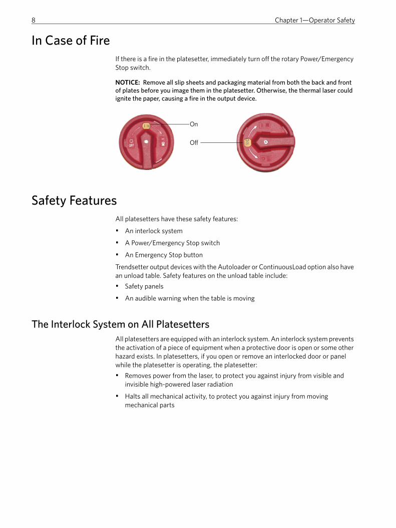
In Case of FireIf there is a fire in the platesetter, immediately turn off the rotary Power/Emergency Stop switch.
Safety FeaturesAll platesetters have these safety features:
• An interlock system
• A Power/Emergency Stop switch
• An Emergency Stop button
Trendsetter output devices with the Autoloader or ContinuousLoad option also have an unload table. Safety features on the unload table include:
• Safety panels
• An audible warning when the table is moving
The Interlock System on All PlatesettersAll platesetters are equipped with an interlock system. An interlock system prevents the activation of a piece of equipment when a protective door is open or some other hazard exists. In platesetters, if you open or remove an interlocked door or panel while the platesetter is operating, the platesetter:
• Removes power from the laser, to protect you against injury from visible and invisible high-powered laser radiation
• Halts all mechanical activity, to protect you against injury from moving mechanical parts
NOTICE: Remove all slip sheets and packaging material from both the back and front of plates before you image them in the platesetter. Otherwise, the thermal laser could ignite the paper, causing a fire in the output device.
On
Off

9
Visible and Invisible High-Powered Laser RadiationLaser emissions from an exposure head are invisible to the naked eye and are very dangerous if they contact skin or eyes. If you open or remove an access panel while the platesetter is operating, the interlock system removes power from the laser.
There are labels on all the access panels that have interlock switches to protect you against visible and invisible high-powered laser radiation. See Laser Interlocked Panel Label on page 18.
Moving Mechanical PartsThe platesetter has a drum that revolves inside the output device. The plates are loaded, wrapped onto the drum, imaged, and unloaded.
The drum normally revolves up to 400 times per minute. If an object hits the revolving drum, the object may become lodged inside the output device and cause damage, including damage to the safety system, thermal imaging head, or protective enclosure. If you open or remove an access panel while the platesetter is operating, the interlock system halts all mechanical activity.
To access the drum for regular preventative maintenance or troubleshooting, you must open the hinged panel at the front of the platesetter. This panel is secured with a solenoid lock (see Solenoid Lock Label on page 20). There are two ways to unlock the front hinged panel:
• Click Unlock in the Print Console device control software. If any jobs are being imaged when you click Unlock, Print Console displays a message asking if you want to cancel them before it sends the unlock command. If the drum is in motion when you click Unlock, the solenoid lock normally does not release until the drum comes to a complete standstill. If you see any mechanical movement when you open the front hinged panel, the platesetter must be repaired.
• Turn the power off and wait five seconds before opening the front hinged panel. The solenoid lock releases as soon as the power is disconnected. If the drum is in motion when you turn off the power, it normally stops revolving within five seconds of the lock being released. If you see mechanical movement after five seconds has elapsed since turning off the power to the platesetter, the platesetter must be repaired.
In either case, if you see mechanical movement that indicates the output device requires repair, do the following actions:
1. Keep your hands away from the moving parts.
2. Turn the rotary Power/Emergency Stop switch to the Off position (see page 11).
3. Close the front hinged access panel.
4. Contact your service representative as soon as possible.
When the lock is released, confirm that the drum has stopped revolving before you start your maintenance or troubleshooting procedure (see Keep Hands Out Label on page 20).
DANGER: Never attempt to operate the output device with any of the access panels open, and never attempt to open or remove access panels while the output device is imaging plates. Tampering with the interlock system can result in serious injury or death from visible and invisible high-powered laser radiation and/or moving mechanical parts.

10 Chapter 1—Operator Safety
Because exposure to a revolving drum can result in serious injury to the operator, service representative, or others in the vicinity of the output device, make sure that you comply with these drum safety messages:
NOTICE: Do not leave any object, tool, or part inside or on the output device enclosure. If an object becomes lodged in the output device, it may damage the output device.
Power/Emergency Stop Switches on All PlatesettersThe Power/Emergency Stop switch disconnects power to the platesetter. The switch is located on the outside of the output device.
Figure 1: Power/Emergency Stop switch on a Trendsetter platesetter
Regular OperationWhen you are instructed to turn off the power to the platesetter for a maintenance procedure, turn the Power/Emergency Stop switch counterclockwise to the Off position. You can secure the switch in the Off position with a padlock to prevent another person from turning on the device while you are performing troubleshooting or maintenance procedures. See Figure 2.
Emergency ShutdownIf the Emergency Stop button is not accessible, turn the Power/Emergency Stop switch counterclockwise to the Off position. The switch disconnects power to the platesetter, which means that you cannot access information about the status of the output device.
DANGER: Do not tamper with the access panel interlock system. Never attempt to operate the output device with any of the access panels open, and never attempt to open or remove access panels while the output device is imaging plates. Tampering with the interlock system can result in serious injury from visible and invisible high-powered laser radiation and/or moving mechanical parts.
WARNING: When opening access panels, keep hands away from moving parts until the revolving drum comes to a complete stop. Mechanical hazards associated with the output device can result in serious injury.
Power/Emergency Stop switch

11
Figure 2: Turn the switch counterclockwise to turn off the power
Emergency Stop Buttons on All PlatesettersThe Emergency Stop button stops laser operation and mechanical movement, but the power remains connected. You can continue to access information about the status of the platesetter. Use this button to stop laser operation and mechanical movement in an emergency situation. It is located inside the output device under the front panel.
If you press this button, you must reset it before the output device can return to normal operation. To reset the button, rotate it 90° clockwise and reset the platesetter.
Figure 3: Location of Emergency Stop button
Safety Panels and Audible Warning on the Unload TablePolycarbonate safety panels are located on the left and right sides of the unload table. Depending on the noise levels in your operating environment, you may also hear a beeping sound when the unload table is lowering to a horizontal position or
Insert padlock herewhen switch is in OFFposition

12 Chapter 1—Operator Safety
rising to an upright position. The panels and the beeping sound help protect against injury when the unload table is moving and from moving parts inside the unload table.
CAUTION: Do not reach into the area protected by the safety panels. Mechanical hazards associated with the unload table can result in injury and/or damage to your output device.
CAUTION: Keep your hands and fingers away from the unload table when you hear the beeping sound. Mechanical hazards associated with the unload table can result in injury and/or damage to your output device.
Safety panels

Labels
Overview...................................................................................................................14
Description of Labels on the Platesetter ..........................................................14
Description of Labels on the Thermal Imaging Head................................... 23
Description of Labels on the Debris Removal Component......................... 25
Description of Labels on Platesetter Options ................................................30
Label Locations ...................................................................................................... 32

14 Appendix A—Labels
OverviewThis appendix contains information about the labels that are located on the:
• Platesetter (next section)
• Thermal imaging head (see page 23)
• Debris removal component (see page 25)
• Options (for example, Autoloader or ContinuousLoad)
These labels are intended to assist you in safely operating your output device. They include information about:
• Device identification
• Compliance with various regulatory standards
• Laser safety
• Mechanical, electrical, and general safety
All the labels described in this appendix are in areas where they can be seen by platesetter operators. The labels that are intended primarily for the safety of service representatives are not included, except for those that are located in areas where operators can also see them.
Description of Labels on the Platesetter
Type of Label For an Illustration Of This Label Go To
Identification and regulatory compliance
Dataplate page 15
Class 1 laser product page 17
Center for Devices and Radiological Health (CDRH) compliance statement page 18
Federal Communications Commission (FCC) compliance statement page 18
Laser safety labels on the access panels
Laser interlocked panel page 18
Laser noninterlocked panel page 19

15
Identification and Regulatory Compliance LabelsThe identification and regulatory compliance labels are located on the power entry box below the Power/Emergency Stop switch.
Identification and certification labels for the Trendsetter output device are located on the lower-right back panel, beside the filters for the compressed air supply.
Figure 4: Identification and regulatory compliance labels
Dataplate Label This label is located on the lower-right back panel, beside the filters for the compressed air supply. There will be one dataplate label in this location, but it may be any of the following examples, depending on the model of the device and the location where it was manufactured.
When you call a service representative, you may be asked to find the serial number for your output device on this label.
Electrical, mechanical, and general safety
High touch current page 19
Hazardous voltage page 21
Fuse replacement page 20
Solenoid lock page 20
Keep hands out until drum has stopped rotating warning page 20
Safety interlock override (danger for service representatives) page 21
Beware of moving parts when interlock deliberately overridden (warning for service representatives)
page 21
Hot surface page 22
Maximum PSI/BAR page 22
Pacemaker warning label page 22
Type of Label For an Illustration Of This Label Go To
Location of identification andregulatory compliance labels

16 Appendix A—Labels
Figure 5: Dataplate label for Trendsetter platesetters made in Canada
Figure 6: Dataplate label for Trendsetter platesetters made in China
Figure 7: Dataplate label for Trendsetter NEWS platesetters made in Canada

17
Figure 8: Dataplate label for Trendsetter NEWS platesetters made in China
Figure 9: Dataplate label for Trendsetter UHR platesetters made in Canada
Class 1 Laser Product LabelThis label is located on the lower-right back panel, beside the filters for the compressed air supply.
Figure 10: Class 1 laser product label
Center for Devices and Radiological Health (CDRH) Compliance Statement LabelThis label is located on the lower-right back panel, beside the filters for the compressed air supply.

18 Appendix A—Labels
Figure 11: CDRH compliance statement label
Federal Communications Commission (FCC) Compliance Statement LabelThis label is located on the lower-right back panel, beside the filters for the compressed air supply.
Figure 12: FCC compliance statement label
Laser Safety Labels on the Access Panels
Laser Interlocked Panel LabelThese labels are located beside the safety interlock switches inside the interlocked protective housing.
Figure 13: Laser interlocked panel label
DANGER: Do not tamper with the access panel interlock system. (See The Interlock System on All Platesetters on page 8.) Tampering with the interlock system can result in serious injury from visible and invisible high-powered laser radiation and/or moving mechanical parts.

19
Laser Noninterlocked Panel LabelThe laser noninterlocked panel label is located on the tool-secured service access covers or panels that provide laser safety.
Figure 14: Laser noninterlocked panel danger label
Electrical, Mechanical, and General Safety Labels
High Touch Current LabelThis label is located on the lower-right back panel, beside the air supply filters.
Figure 15: High touch current label
Hazardous Voltage LabelThis label is found in the fan box, on the service access cover for the junction box.
DANGER: The service access covers or panels can be removed only by a service representative. Do not remove covers or panels bearing this label. Accessing the areas protected by these covers or panels can expose you to serious injury from visible and invisible high-powered laser radiation and/or moving mechanical parts.
DANGER: Service access covers can be removed only by an authorized service representative. Do not remove covers bearing this label as these areas contain high-voltage components that can cause severe electrical shock, which could result in serious injury or death.

20 Appendix A—Labels
Figure 16: Hazardous voltage label
Fuse Replacement LabelThis label is located inside the power box panel, at the lower-left side, below the service access panel.
Figure 17: Fuse replacement label
Solenoid Lock LabelThis label is located beside each latch on the front panel.
Figure 18: Solenoid lock label
Keep Hands Out LabelThis label is located behind the front panel, in the middle of the leading-edge clamp.

21
Figure 19: Keep hands out label
Safety Interlock Override Label (for Service Personnel)This label is located beside the safety interlock override switch on the power box panel.
Figure 20: Safety interlock override label
Beware of Moving Parts When Interlock Deliberately Overridden Label (for Service Personnel)This label is located behind the front panel on both ends of the leading-edge clamp. If the platesetter is equipped with the Autoloader option, it also appears on the picker assembly. See Beware of Moving Parts When Interlock Deliberately Overridden Label (for Service Personnel) on page 30.
DANGER: The service safety interlock override key switch is for use only by an authorized service representative. Unauthorized use can expose you to serious danger from visible and invisible high-powered laser radiation, moving mechanical parts, and/or electrical shock, which could result in serious injury or death.

22 Appendix A—Labels
Figure 21: Beware of moving parts when interlock deliberately overridden label
Hot Surface LabelThis label is located on the heat exchanger circulating pump inside the fan box panel.
Figure 22: Hot surface label
Maximum PSI/BAR LabelThis label is located near the compressed air inlet connector.
Figure 23: Maximum PSI/BAR label
Pacemaker Warning LabelThis label is located on the magnetic clamps.
CAUTION: Operators with implanted cardiac pacemakers should keep magnetic clamps more than 7 cm (2.75 in.) away from their pacemaker. If you have additional concerns, consult your physician and/or the manufacturer of your implant.

23
Figure 24: Pacemaker warning label
Description of Labels on the Thermal Imaging Head
Identification and Regulatory Compliance Labels
Dataplate LabelIdentification and regulatory compliance labels for the thermal exposure heads are located on the rear panel of the exposure head enclosure. The dataplate label in this location may be any of the following examples, depending on the model. See Location of laser safety labels on the thermal imaging head on page 32.
Figure 25: Dataplate label for thermal imaging head model 1.7
Type of Label For an Illustration of This Label Go To
Identification and regulatory compliance
Dataplate thermal 1.7 head page 23
Dataplate thermal 2 head page 24
Laser safety Exposure head aperture page 24
Laser hazard/Class 4 laser product/radiation output page 25

24 Appendix A—Labels
Figure 26: Dataplate label for thermal imaging head model TH2
Imaging Head Aperture LabelThis label is located on top of the thermal imaging head protective housing, pointing to the shutter and aperture at the front of the thermal imaging head protective housing. See Location of laser safety labels on the thermal imaging head on page 32.
Figure 27: Exposure head aperture label
Laser Hazard/Class 4 Laser Product Label/Radiation OutputThe laser hazard/Class 4 laser product /radiation output safety label is located on the back of the thermal imaging head protective housing. See Location of laser safety labels on the thermal imaging head on page 32. There is one dataplate label in this location. It will be one of the following examples, depending on the model.

25
Figure 28: Laser hazard/Class 4 laser product/Radiation output: thermal 1.7 head or thermal 2 head
Figure 29: Laser hazard/Class 4 laser product/Radiation output: thermal 3 head
Description of Labels on the Debris Removal ComponentTrendsetter platesetters may or may not have a debris removal component, depending on the type of media they use. If they do require debris removal functionality, a UDRC will be part of the platesetter system.
Type of Label For an illustration of This Label Go To
Identification, configuration, and regulatory compliance
Dataplate page 26
External venting option page 26
BP configuration (external venting option) page 27
HP configuration (internal venting option) page 27
Airborne emissions Particulate airborne emissions page 28
Gaseous and particulate airborne emissions page 29

26 Appendix A—Labels
Identification, Configuration, and Regulatory Compliance LabelsThe identification, configuration, and regulatory compliance labels are located to the left and to the right of the power entry box at the back of the UDRC, as shown in Figure 30.
Figure 30: Identification and Certification labels
This label is located near the power entry box.
Figure 31: Dataplate label for Debris Removal Cabinet Model UDRC
External Venting Option LabelThe External Venting Option label is located on the rear panel of the external venting option unit. If your debris removal unit has this label, it also has the Gaseous and Particulate Airborne Emissions label (see page 29) and the BP Configuration label (see page 27).
FCC label
UDRC Configurationlabel
Power entry box
100 label
Identification(Dataplate) label

27
Figure 32: External Venting Option label
Configuration LabelsThe configuration label is located to the left of the power entry box.
BP Configuration Label
Figure 33: BP Configuration label
HP Configuration Label
Figure 34: HP Configuration label
28 Appendix A—Labels
FCC Certification LabelThe FCC Certification label is located to the right of the power entry box.
Figure 35: FCC Certification label
Airborne Emissions Labels
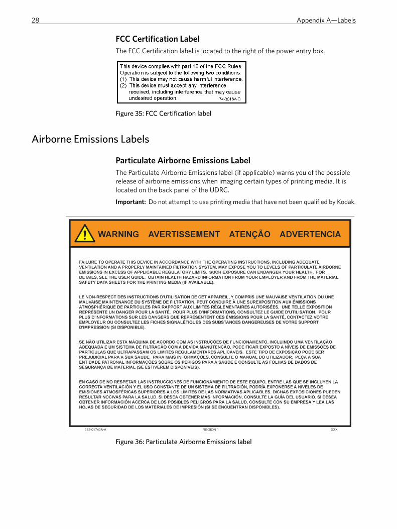
Particulate Airborne Emissions LabelThe Particulate Airborne Emissions label (if applicable) warns you of the possible release of airborne emissions when imaging certain types of printing media. It is located on the back panel of the UDRC.
Figure 36: Particulate Airborne Emissions label
Important: Do not attempt to use printing media that have not been qualified by Kodak.

29
Gaseous and Particulate Airborne Emissions LabelThe Gaseous and Particulate Airborne Emissions label (if applicable) warns you of the possible release of airborne emissions when imaging certain types of printing media. It is located on the back panel of the UDRC, just above the electronics enclosure.
Figure 37: Gaseous and Particulate Airborne Emissions label
General Safety
Stability Caution LabelThe Stability Caution label is located on the underside of the inner lid. It is visible when the cabinet lid is raised to the open position.
Important: Do not attempt to use printing media that have not been qualified by Kodak.

30 Appendix A—Labels
Figure 38: Stability Caution label
Description of Labels on Platesetter Options
Beware of Moving Parts Label (on devices with unload tables)On Trendsetter platesetters with the Autoloader or ContinuousLoad option, this label is located on both ends of the unload table (see Safety Panels and Audible Warning on the Unload Table on page 11).
Figure 39: Beware of moving parts label
Beware of Moving Parts When Interlock Deliberately Overridden Label (for Service Personnel)This label is located on the picker assembly on the Autoloader option.
Type of Label For an Illustration Of This Label Go To
Mechanical safety Beware of moving parts on unload table page 30
Beware of moving parts when interlock deliberately overridden (warning for service representatives)
page 30

31
Figure 40: Beware of moving parts when interlock deliberately overridden label

32 Appendix A—Labels
Label Locations
Location of Labels on the Thermal Imaging Head
Figure 41: Location of laser safety labels on the thermal imaging head
Exposure head aperture label
Laser hazard warningClass 4 laser productRadiation output
Dataplate

Regulatory Compliance
Regulatory Approval Model Designation........................................................34
Compliance With Standards for Electrical and Mechanical Safety ..........34
Compliance With Standards for Laser Safety ................................................ 36
Compliance With Standards for Electromagnetic Interference and Electromagnetic Compatibility .......................................................................... 37
Compliance With Standards for Noise Emissions ........................................ 37

34 Appendix B—Regulatory Compliance
Regulatory Approval Model DesignationTSM is the regulatory approval model designation for the Trendsetter output device. The regulatory approval model designation name appears on the dataplate label (for an example of this label, see page 15) and all regulatory approval documents.
Compliance With Standards for Electrical and Mechanical Safety
The Trendsetter output device has been designed, tested, and evaluated for compliance with these electrical and mechanical safety standards:
• CSA 60950-1 Information Technology Equipment —Safety—Part 1
• UL 60950-1 Information Technology Equipment—Safety—Part 1
• EN 60950-1 Information Technology Equipment—Safety—Part 1
• EN 60204-1 Safety of Machinery, Electrical Equipment of Machines
The CSA International “C CSA US” mark on the dataplate label (for an example of this label, see page 15) indicates compliance with these standards:
• CSA 60950-1 Information Technology Equipment —Safety—Part 1
• UL 60950-1 Information Technology Equipment—Safety—Part 1
The CE mark on the dataplate label indicates compliance with the following directives:
• Low Voltage Directive 73/23/EEC
• Directive of Machinery 98/37/EC
• Directive of Electromagnetic Compatibility 2004/108/EC
EC Declaration of Conformity for the Platesetter and Its Options

35
Figure 42: EC Declaration of Conformity

36 Appendix B—Regulatory Compliance
EC Declaration of Conformity for the Filtration Unit
Figure 43: EC Declaration of Conformity for the debris removal unit
Compliance With Standards for Laser SafetyThe Trendsetter output device has been designed, tested, and evaluated for compliance with the following laser safety standards:
• U.S. Federal Regulations 21 CFR 1040.10, in accordance with the regulations of the Center for Devices and Radiological Health (CDRH) of the U.S. Food and Drug Administration
• EN 60825-1, Safety of Laser Products

37
The Class 1 Laser Product label on the output device indicates compliance with these standards. For an example of this label, see page 17.
Compliance With Standards for Electromagnetic Interference and Electromagnetic Compatibility
Electromagnetic Interference (EMI)The Trendsetter output device has been tested and found to comply with the limits for a Class A digital device, pursuant to part 15 of the FCC Rules. These limits are designed to provide reasonable protection against harmful interference when the output device is operated in a commercial environment.
This equipment generates, uses, and can radiate radio frequency energy and, if not installed and used in accordance with this guide, may cause harmful interference to radio communications. Operation of the output device in a residential area is likely to cause harmful interference. You must correct the interference at your own expense.
The FCC compliance statement label on the output device indicates compliance with these limits. For an example of this label, see page 18.
Electromagnetic Compatibility (EMC)The Trendsetter output device has been designed, tested, and evaluated for compliance with the Directive of Electromagnetic Compatibility 2004/108/EC. It complies with the following EMC standards:
• EN 55022, Class A
• EN 55024
• EN 61000-3-3
Compliance With Standards for Noise EmissionsThe Trendsetter output device has been designed, tested, and evaluated for compliance with the maximum noise emission limit permitted for an office environment, 70 dB(A). Noise emissions from the Trendsetter output device will not exceed 69 dB(A) when tested in accordance with EN ISO 7779:2001, Acoustics — Measurement of airborne noise emitted by information technology and telecommunications equipment.
WARNING: Use of controls or adjustments or performance of procedures other than those specified in the help system or visual reference guide may result in hazardous radiation exposure.

38 Appendix B—Regulatory Compliance

Bbeware of moving parts label, 30beware of moving parts when interlock
deliberately overridden label, 21, 30
Ccaution safety messages, about, 4CDRH compliance statement label, 17,
36CE mark, 15, 34Center for Devices and Radiological
Health, 36clamps, hazards related to
damage to drum, 7pacemaker interference, 7pinched fingers, 7
Class 1 laser product label, 17, 37Class 4 laser product label, 24, 25, 32cleaning solutions, 7compliance. See Regulatory Compliancecompressed air, hazards related to, 7, 22CSA 60950-1, 34CSA International mark, 15, 24, 34C-Tick, 15
Ddanger safety messages, about, 4dataplate label, 15, 34date of manufacture, 15, 24Declaration of Conformity. See EC
Declaration of ConformityDirective of Electromagnetic
Compatibility 2004/108/EC, 34, 37Directive of Machinery 98/37/EC, 34
EEC Declaration of Conformity, 34, 35,
36electrical rating, 15electrical safety
fuse replacement label, 20hazardous voltage label, 6, 19high touch current label, 19overriding safety interlock, 21service key switch, 5, 21shock hazard from liquids, 6standards, 34turn off electrical power, 10unauthorized panel removal, repairs,
changes, 5emergency stop
button, 11switch, 10
EMI/EMC compliance, 37emissions, 6EN 55022, Class A, 37EN 55024, 37EN 60204-1, 34EN 60825-1, 36EN 60950-1, 34EN 61000-3-3, 37environmental specifications, 37exposure head aperture label, 24, 32
Ffan box, 19, 22FCC Certification label, 28FCC compliance statement label, 18, 37filters, 4, 7fire, 8fuse replacement label, 20
GGaseous and Particulate Airborne
Emissions label, 29gaseous emissions, 6gloves, protective, 7
Hhazardous voltage label, 6, 19high touch current label, 19hot surface label, 22
Iidentification labels, 15Information Technology Equipment, 34installation, safety guidelines, 3interlock system, 5, 10
Kkeep hands out label, 20
Llabels
beware of moving parts, 30beware of moving parts when
interlock deliberately overridden, 21, 30
CDRH compliance statement, 17CE mark, 15, 34Class 1 laser product, 17, 37Class 4 laser product, 25, 32CSA International mark, 15, 24, 34dataplate, 15, 34exposure head aperture, 24, 32
FCC Certification, 28FCC compliance statement, 18fuse replacement, 20Gaseous and Particulate Airborne
Emissions, 29hazardous voltage, 6, 19high touch current, 19hot surface, 22identification, 15keep hands out, 20laser hazard, 25laser interlocked panel, 18laser noninterlocked panel, 19maximum PSI/BAR, 22pacemaker warning, 23Particulate Airborne Emissions, 28radiation output, 24, 32regulatory complicance, 15safety interlock override, 21solenoid lock, 20Stability Caution, 29UDRC-BP Configuration, 27UDRC-HP Configuration, 27
laser hazard label, 25laser interlocked panel label, 18laser noninterlocked panel label, 19laser safety
Class 4 laser product label, 25, 32emergency stop button, 11exposure head aperture label, 24, 32interlock system, 8labels on access panels, 18labels on exposure head, 23laser hazard label, 25laser interlocked panel label, 18laser noninterlocked panel danger
label, 19panel removal, 5, 10radiation output label, 24, 32safety interlock override label, 21service access only, 5standards, 36unauthorized repairs, 5
liquids, hazards related to, 6Low Voltage Directive 73/23/EEC, 34
Mmagnetic clamps, hazards related to
damage to drum, 7pacemaker interference, 7pinched fingers, 7
maintenance, safety guidelines, 4manufacture date, 15, 24Material Safety Data Sheet, 6maximum PSI/BAR label, 22
Index

40 Trendsetter Model TSM Safety Guide
mechanical safetybeware of moving parts label, 30beware of moving parts when
interlock deliberately overridden label, 21, 30
keep hands out label, 21laser interlocked panel label, 18laser noninterlocked panel danger
label, 19removing panels, 5, 6, 10repairs needed, 9safety interlock override label, 21standards, 34unload table, 7, 8, 11, 30
media, hazards related togaseous emissions from unqualified
media, 6sharp plate edges, 7
messages, safety, 4MSDS, 6
Nnoise emissions, 37notice messages, about, 4
Ooperation, safety guidelines, 3
Ppacemaker warning, 7, 23panels
interlock defeated, 18interlock system, 9noninterlocked, 19removal, 5, 10safety, 7, 11service access only, 5, 19
Particulate Airborne Emissions label, 28plates, hazards related to
gaseous emissions from unqualified media, 6
sharp plate edges, 7power box, 20, 21power switch, 8, 9, 10PSI/BAR, maximum, 22
Rradiation output label, 24, 32regulatory approval model, 34regulatory compliance
electrical safety, 34EMI/EMC, 37labels, 15laser safety, 36mechanical safety, 34noise emissions, 37
repairs, 5
Ssafety
electrical, 34laser, 36mechanical, 34
safety features, 8safety interlock override label, 21safety messages, about, 4Safety of Laser Products, 36Safety of Machinery, 34safety panels, 11serial number, 15, 24service access only, 3, 5, 21, 30service key switch, 5, 21slip sheets, hazards related to, 7solenoid lock label, 20Stability Caution label, 29
Tthermal exposure heads, labels, 23TSM, 34
UUL 60950-1, 34unload table, 7, 8, 11, 30
Vvoltage, hazardous, 6, 19
Wwarning safety messages, about, 4water, hazards related to, 6