transport and road research laboratorytransport and road research laboratory - department of the...
TRANSCRIPT

TRANSPORT and ROAD RESEARCH LABORATORY
- Department of the Environment
TRRL REPORT LR 593
LARGE-DEFLECTION ELASTO-PLASTIC BUCKLING ANALYSIS OF PLATES USING FINITE ELEMENTS
by
M.A. Crisfield, BSc, PhD
Bridge Design Division Structures Department
Transport and Road Research Laboratory Crowthorne, Berkshire
1973

Ownership of the Transport Research Laboratory was transferred from the Department of Transport to a subsidiary of the Transport Research Foundation on I st April 1996.
This report has been reproduced by permission of the Controller of HMSO. Extracts from the text may be reproduced, except for commercial purposes, provided the source is acknowledged.

CONTENTS
Abstract
1. Introduction and review of previous work
1.1 Geometric non-linearity
1.2 Material non-linearity
1.3 Combined geometric and material non-linearities
2. Theory
2.1 Assumptions
2.2 Hasticity -- 'volume approach'
2.3 Plasticity - 'area approach'
2.4 Formulation of large-deflection elastic-plastic equations
2.5 Application of the finite element idealisation
3. Numerical approach
3.1 Shape functions and element details
3.2 Formation of element tangent stiffness matrix and internal load vector
3.2.1 Volume approach
3.2.2 Area approach
3.3 Methods of solution
3.4 Convergence
3.5 Refinements to basic theory
3.5.1 Acceleration of convergence
3.5.2 Plasticity
4. Elastic examples
4.1 Simply supported plate subject to uniformly distributed lateral load
4.2 Simply supported plate subject to uniaxial in-plane load
5. Elastic-plastic examples
5.1 Simply supported imperfect plates subject to uniaxial in-plane loads
5.1.1 Convergence, iterations and computer time
5.1.2 Hates without residual stresses
5.1.3 Hates with residual stresses
5.2 Simply supported imperfect plates subject to in-plane shear loads
5.2.1 Fully restrained and unrestrained plates
5.2.2 Hate with intermediate restraint
6. Conclusions
7. Acknowledgements
8. References
9. Nomenclature
9.1 Subscripts
9.2 Superscripts
9.3 Vectors
Page
1
1
1
1
2
2
3
3
4
5
7
8
8
9
9
9
10
10
10
10
11
12
12
12
12
12
12
13
14
14
14
16
17
18
18
23
24
24
24

10.
11.
9.4 Matrices
9.5 Programs
Appendix 1 : Derivation of tangential elasto-plastic matrices for 'area approach'
Appendix 2 : Computing details
Page
25
25
25
27
Q CROWN COPYRIGHT 1973 Extracts from the text may be reproduced
provided the source is acknowledged
LARGE-DEFLECTION ELASTO-PLASTIC BUCKLING ANALYSIS OF PLATES USING FINITE ELEMENTS
ABSTRACT
The formulation of the large deflection behaviour of elastic-plastic plates is given and numerical solutions obtained using the finite element method. Illustrative examples include the collapse analysis of plate panels subject to compression and shear respectively.
1. INTRODUCTION AND REVIEW OF PREVIOUS W O R K
Recent research work on box-girder bridges has highlighted the need for theoretical methods for the analysis of thin plates and stiffened plate panels that can predict their behaviour up to and, if possible, beyond their maximum load- carrying capacities. The methods should be able to include the effects of imperfections and residual stresses as well as to allow for plasticity. In such circumstances the solution of the linear buckling problem is not directly applicable, and a large-deflection elastic-plastic analysis is required.
The non-linear analysis of plates and shells has been treated by classical (series) methods(I-5), finite differ- ences(6-11), dynamic relaxation(5,12,13), perturbation analysis(14,15) and, for restricted classes of problem, by the use of Ritz procedures(I 6-18). However, partially as a result of its greater flexibility, the finite element method(19-59) appears to be the most popular numerical approach. A piecewise integration process is involved and, as a consequence the finite element method is particularly appropriate for elastic-plastic problems in which plasticity produces areas of varying stiffness. Since the finite element method has been chosen for the work described herein, the following review of previous work will concentrate on this method of analysis.
1.1 Geometric non-linearity
The pioneering non-linear work on finite elements is due to Turner et al(19). Most of the earlier analysis related primarily to the linear buckling problem(20-23). Incremental approaches were at first adopted(19, 24-26) for tracing the complete load-deflection characteristics of a structure. This process involves the so-called geometric stiff- ness matrix and an updating of co-ordinates. Mallet and Marcal(27) showed that a Lagrangian (fixed co-ordinate) system could be adopted if an 'initial displacement' matrix was added to the formulation. This approach was more economic than the updating system and gave better solutions when a small number of elements were employed(28,29).
Unfortunately, the incremental approach can lead to an unquantifiable build-up of error and, to counter this problem, Newton-Raphson iteration(27,30) and direct search( 31,32) methods were adopted. For problems involving instability, however, there is a danger of a lack of convergence or, possibly, convergence to a higher equili- brium state. For this reason Connor and Brebbia(33) recommended a combination of incremental and Newton- Raphson procedures. A combination of iterative and incremental techniques was also advocated by Murray and Wilson(34,35). Whereas Connor and Brebbia(33) used an initial displacement matrix, Murray and Wilson relied on up-dating the co-ordinates. Instead of using the Newton-Raphson method in which the stiffness matrix is continuously up-dated a modified Newton-Raphson procedure(36-38) may be adopted in which the out-of-balance load vector is applied to the unaltered stiffness matrix. For problems involving instability, however, up-dating of the stiffness matrix is essential if a check is to be kept on the stability of the equilibrium path.
1.2 Material non-linearity
Non-linear effects due to plasticity have been tackled in a manner similar to the approaches used for geometric non-linearities. A tangent elastic-plastic modular matrix has been developed(39-42) which relates the incremental stresses to the incremental strains. This tangential modular matrix, which is a function of the current stress levels, may be incorporated in an incremental procedure(37,43) or, alternatively, in a modified Newton-Raphson (initial
stress) approach (37,42-44). Small increments are desirable in elastic-plastic analysis as a consequence of the incre- mental nature of the flow rules. Nayak and Zienkiewicz(44) have, however, recently used larger load increments for

the application of the out-of-balance load vector while, for the formation of this vector, a further sub-division is employed to improve the accuracy of the representation of the flow rules.
A number of authors(45-49) have used the finite element method for the analysis of elastic-plastic plate problems. Ang and Lopez(46) (using a discrete model approach) and Belytschko and Velebit(49) (using a comple- mentary energy formulation) have simplified the problem by assuming sudden plastification of the whole section depth. Similar approximations have been made using finite differences(8,9). A more exact analysis was preferred by Armen et al(47) and Marcal(43,50) who allowed for the progressive growth of plasticity through the depth of the plate. Armen et al(47) also traced the elastic-plastic interfaces across the plane of the element while, at the other extreme, Marcal considered the plastic properties to be constant over each layer. Whang(48) analysed a shell by dividing it into six slices, whilst Marcal used the trapezoidal rule with elevent integration stations through the depth.
1.3 Combined geometric and material non-linearities
Early work in the field of combined non-linearities was concerned with the buckling of fiat plates( 51,52) e.g. using the Stowell-Ilyushin( 60,61) plastic buckling theory. An approximate combination of geometric and material non-linearities has been given by Murray and Wilson(53) who extended their earlier work on elastic large- deflection analysis(34,35). They used deformation theory for the material non-linearity and reduced the tangent and secant moduli of the material by relating the effective stress and effective strain to the uni-axial stress-strain curve. It follows that the material non-linearity is assumed to give rise to an isotropic reduction in stiffness, whereas in practice an anisotropic reduction is experienced. Examples relating to cylindrical bending were given.
A partial combination of the two non-linear effects has been given by Armen et a1(47), who considered a flat plate with Constant membrane load subject to varying lateral load. The same authors described a full inter- action of the two non-linearities for the analysis of a beam and a shallow arch. The combined non-linear analysis of axi-symmetric shells of revolution has been described by Marcal(28,54), Gerdeen et a1(55), and Stricken et a1(56). In each case eleven integration stations were used through the depth of the shell. The integration process within the element is considered in some detail by Stricklin et a1(56). The trapezoidal rule was initially used for integration through the depth of the plate, but Simpson's rule was later adopted. This change led to more accurate results for a smaller number of integration stations. Simpson's rule was preferred to Gaussian quadrature since the latter method does not accurately predict the surface stresses. This restriction is, however, unlikely to be of major importance from the point of view of predicting collapse loads. Marcal(28) gave the load/central-deflection curve for a simply supported plate under lateral load. A large deflection elastic-plastic program was used for the analysis in which only four triangular elements were employed (for a symmetric octant of the plate). Unfortunately, very few details are given.
The very considerable computer time required for non-linear analysis(29, 56) (particularly for combined non- linearities) probably accounts for the dearth of literature relating to case studies of the full large-deflection analysis of elastic-plastic plates. It is also probably for economic reasons that the most useful solutions for real plate problems(16-] have not used conventional finite element techniques. Instead, Ritz type variational procedures have been used which are restricted to specific boundary conditions. Graves-Smith(17,18) simplified the analysis further by assuming that the deflections were of the same form as those immediately after buckling. Analytical expressions were derived for these deflections. Moxham(16), who considered plates in direct compression, adopted a more conventional Ritz approach in which eight Fourier coefficients were used to represent the plate deflections u, v and w. For calculating the potential energy, the quarter plate was divided into 405 units of volume (9 x 9 x 5). The energy was minimized using an iterative minimization procedure due to Powell(62) and plasticity was included by means of a combination of flow and deformation theories.
2. THEORY
The present theory relates to two formulations. The first involves a volume integral and is based on von Mises' yield criterion. This method will be referred to as the 'volume approach'. The second method uses an approximate yield criterion given by Ilyushin(63) which relates to the six generalised stress resultants in a shell (Nx,Ny,Nxy,Mx,My,Mxy)2
* The notation used throughout the report is given in Section 9.
2

The yield criterion pre-supposes a sudden plastification of the plate section in a similar manner to that frequently assumed for plate bending(8,9,49). This formulation will be referred to as the 'area approach'. It is not as accurate as the 'volume approach', but has the advantage of a considerable saving in computer time. A somewhat similar method using finite dif- ferences has been proposed (but not applied) by Massonet(64).
2.1 Assumptions
Certain basic assumptions are made in both approaches. They are:
(1)
(2)
Thin plate theory appliesso that transverse shear deformation is neglected and plane sections remain plane.
A Lagrangian (fixed) co-ordinate system is used. This formulation is valid provided that the slopes ~-~, 3.__ww < < 1. by
(3) Ideal elastic-perfectly plastic behaviour is assumed with no strain hardening.
2.2 Plasticity -- 'volume approach"
It is assumed that Oz = 0 throughout the plate. Consequently at any level z, plasticity is governed by the von Mises' yield criterion:
(f)z = + (Ox 2 + Oy 2 - OxOy + 3Txy 2) ~< 1
For plastic flow, f remains on the yield surface so that of = 0
The Prandtl-Reuss flow rules give:
ap} = xfbf ' l e z " l . b o j z
........................... (2.1)
........................... (2.2)
........................... (2.3)
where h is a positive scalar. The incremental stress-strain laws are given by:
{AO}z = [E]((Aet}- {Aep}}z ........................... (2.4)
From equations (2.1)--(2.4) (following Zienkiewicz et al(42) and Yamada et al(41)), the relationship between the increments of stress and the increments of total strain may be written as:
( A a } z = [E*(o)~ z {Act} z ........................... (2.5)
where [E*(o)3 z is the tangential elasto-plastic modular matrix which is a function of the current stress level. It is given by:
[E*(o)]z = [E] [ [I] - 1 [o][E]] ........................... (2.6)
_ 3f EE]~33f} and [o] (~fo} {33f} T where r - ( ~ o } T = ..... ...................... (2.7)
If the incremental stress resultants(AN} , { AM} are defined by:
. . . . . . . . . . . . . . . . . . . . . . . . . . . ( 2 . 8 )
t
{ a o } dz f t 2 t 2{o}
f . t z A dz
2 3

and the total strain is assumed to vary linearly through the plate such that:
( A e t ) z = ( A e t ) + z ( A X t ) ............................. (2.9)
where (Aet} defines the mid-section strains at z=0, and (AXt) defines the (negative)curvatures (see equation (2.22)), then combining equations (2.5), (2.8) and (2.9) gives:
( A N ) = [C*] v ( A e t ) + [cd]v ( /kXt) ) .............................. (2.10)
( A M ) = [cd']v ( A e t ) + [D*]v (/XXt)
where [C*] v , [cd] v and [D*] v are the tangential elasto-plastic modular matrices that relate to the generalised stress resultants. They are given by:
2.3
[C*]v = f [E*(o)lz dz
[D*lv = f z 2 [E*(o)] z dz
[cdl v = f z [E*(o)l z dz
Plasticity - - "area approach"
.............................. (2.11)
Using deformation theory, Ilyushin(63) derived the following approximate yield surface for a shell*:
4sMN 16M f - 2 2 + 2 + 4 2 <~ l t o o x /3 t 3 o o t o o
where N, M and MN are quadratic 'stress intensities' given by:
= Nx2 + Ny 2 - N x N y + 3Nxy 2
= Mx 2 + My 2 - M x M y + 3Mxy 2
M--N = M x N x + MyNy - ½M xNy -- ½MyN x
MN and s = IM--NI
.............................. (2.12)
+ 3Mxy Nxy ............................... (2.13)
For plastic flow f must remain on the yield surface and
where
6 f = { fn ) T {/XN) + £ f m } T {~dVl} = 0
__ 16 {-~M} { fm) = 2s { ~ N } + t4 x /~t 3
.............................. (2.14)
............................. (2.15)
It is assumed that the expression in equation (2.12) may be treated as a plastic potential such that the generalised plastic strain rates are proportional to the partial derivatives of the potential (normality law).
i.e ( A e p ) = X ( f n ) ) .............................. (2.16)
( A X p ) = X ( f m }
* Massonet(64) omitted the M-N term.
4
Following a procedure very similar in form to that previously given for the 'volume approach', the following incremental 'stress'-'strain' laws are derived:
( A M } = { A N } = [cd] T[C*]A {Act} +{Aet}+ [D*]A[Cd]A {&Xt}{ Axt} } ............................. (2.17)
The full derivation of equations (2.17) is given in Appendix 1. Equations (2.17) are of the same form as the corres- ponding equations (2.10) derived for the 'volume approach'. In the present expressions, however, the tangential elasto-plastic modular matrices [C*] A, [D*] A and [cd] A are each functions of the six current generalised stress resultant, {N} , {M} (see Appendix 1). This is in contrast to the 'volume approach' in which the modular matrices [C*] v, [D*] v and [cd] v are functions of the stress levels { o} z through the depth of the plate.
2.4 Formulation of large-deflection elastic-plastic equations
In the absence of body forces, the potential energy of the plate may be written as:
c0+ f(feo=ede)'dv- f-P1 (Pl - P o ) ' d S ......... ....................... (2.18) V e=t3 0 (see Figure 1)
An increment of the total potential energy is given by:
A , = f ( ( ° } T {Ae} + ½ {Ao} T {Ae}) v dv - fs (P + AP). Ap. aS - fs AP (P-Po) dS
................................. (2.19)
The last term of expression (2.19) does not involve the increments of deflection Ap. It will therefore vanish when variations with respect to Ap are made on the total potential energy. For this reason the term will be omitted from the following development.
The strains in the plate are related to the displacements with the aid of the Kirchoff assumptions (plane sections remain plane),
a___Ew } u z= Uz= o - z 3x ................................ (2.20)
a__w v z = Vz= o - z 3y
aw aw With the assumptions ax , ay ,~ 1, the strains may be written as:
{qz = {,+} , z {x}
I " t au ½ ax
where { e } = ' { + ) = ' ~ ½ ay
~y + ~x ax a y
................................ (2.21)
f a2w t a--7
{ x } = , -- aye
_ a2w
................................ (2.22)
5

The incremental strains are given by:
{~o)z= { ~ } + (TS~ { ~ s } + {~+} + z {~x} +
where {Ae-} , {Ae} and {AX} are obtained from {e-} , {+} and by the increments Au, Av and Aw. {As} and [TS] are given by:
re1 {~s} = p a w ! , ITs)
l a Y . )
-a__w o ax
aw = o ay
aw aw ay ax
. . . . . . . . . . . . . . . . . . . . . . . . . . . . . . . . . ( 2 . 2 3 )
{X} by replacing u, v and w
................................ (2.24)
It is convenient to re-write equation (2.23) in the form:
where {/~el} = {A~-} 4- [TS] { ~s} + Z {AX}
contains all the linear functions of the generalised strain increments, and { k +} Substitution from equations (2.26) into equation (2.19) gives:
~ = *v {°}~ {<} ~V+Sv {°}~ {~'+} ~ v + ~ s v
The second term of this expression (equation (2.27)) may be re-written as:
. . . . . . . . . . . . . . . . . . . . . . . . . . . . . . . . (2.25)
................................. (2.26)
contains the non-linear terms.
{ Ao} T {/~e} z dV _ fS (P+ AP).Ap dS
. . . . . . . . . . . . . . . . . . . . . . . . . . . . . . . . . ( 2 . 2 7 )
s { ~ } T [~] (~} . ~
+ IN x Nxy ] t where [N] = and {N} = f 2 {O}z dz xy Ny j .t
Substituting from equations (2.23) - (2.26) and (2.8) into equation (2.27) gives:
,,,i, = ~ s~ ¢ {,,N}'r { {,,~-} + { , ¢ } +
{,,,} • [~ {,,s}.) dA + ., @ } ~ { {,,~-}
................................. (2.28)
+ r r s l { ~ } } + { ~ } ~ { ~ } ) d A - ,s O, -,- ~,~ ,'
................................. (2.29)
where {M} are the total bending moments acting on the section. They are given by:
{ ~ } = t z {O}z ~z ................................ ~.~0~ -t
Equations (2.10) (volume) and (2.17) (area) give the incremental 'stress' - 'strain' laws. In these equations (Aet } refers to the total strain increment at the mid-section z = 0. Hence:
{ Act} = ( A e } + iTS] {/ks} + {A~} ................................ (2.31)
6

Substituting from equations (2.10) (or (2.17)) and (2.31) into equation (2.29) gives * •
+ ½ fA (As}T t~] (As} dA
-- J; ( ( U + ALl) Au + ( V + AV) Av) dS - fA (W + AW) Aw dA
{ ~ } T [TSl T [C*I[TS] ~As} + {ZXX} T [D*l { a X }
+ 2 {Ae} T [cdl {AX} + 2 (A~} T [TSl T [ c d l { A X } ) dA
.............................. (2.32)
2.5 Application of the finite element idealisation
At this stage in the formulation, the usual finite element idealisations are made,
i.e. A ~ = 2~ Adp structure elements
............................. (2.33)
Also, shape functions are introduced relating the field displacements to the nodal values. It ~11 be assumed that differ- entiation of the chosen shape functions leads to:
= } {X} = [F] {w} ............................. (2.34)
Precisely the same relationships exist between the incremental 'strains' and the incremental nodal 'displacements'.
Substituting for the incremental 'strains' into equation (2.31) and applying the principle of stationary total potential energy, 8 (Aq~) = 0 ............................. (2.35)
gives {P} + {AP} - (P} = [KE] (Ap} ............................. (2.36)
where [KE] is the tangent stiffness matrix of the element, given by:
[Kill [Kio] [KE] = [KiolT [Koo ]
.............................. (2.37)
where [Kii], [Kio] and [Koo ] are sub-matrices given by:
[Kii] = fA [HIT [C*] [H] dA
[Kool = fA([FIT [D*] [F] + [B] T [TSI T [C*] [TS] [B] +
+ [B] T [TS] [cd] [F]) dg
[Kio] = fA ([H]T [C*] [TS] [B] + [HI T [cd] [El) dA
[B]T + [N] [B] + [F] T [cd] T [TS] [B]
. . . . . . . . . . . . . . . . . . . . . . . . . . . . . . ( 2 . 3 8 )
• T0rmsinvo, ng }T +} 0o to nsordo oo three or four) have been neglected in the derivation of equation (2.32).
7
¢ "1 ~tAP~ and ~Apj ~ are the nodal values of the incremental forces and displacements respectively.
i.e. { A P } = AV , {Ap} = Av ............................. (2.39)
t~ "1
~P .~ is the corresponding vector of total external forces prior to the application of the incremental loads and { P} is an 'internal load vector' given by:
{ { P } - - ( P } } may be considered as an out-of balance load vector.
This term vanishes if the external forces and internal 'stre, sses' are in exact equilibrium at the onset of the load increment.
The tangent stiffness matrix [KE] and the internal load vector { P} have been expressed in equations (2.38) and (2.40) as area integrals. When the volume approach is adopted, however, the terms [D*] , [C*] and [cd] (equations (2.11)), [ ~ ] , {N) and {M} (equations (2.38)and (2.32))involve an integration through the depth z. Consequently, for this approach, the formation of [KE] and { P ) involves a volume integral.
3. N U M E R I C A L APPROACH
3.1 Shape functions and element details
The present investigation was initiated with a view to the analysis of steel panels in box-girder bridges. Such panels are generally rectangular in shape so that it is convenient to use rectangular elements. (A modification to general quadrilateral elements is possible). The out-of-plane deflections, w, are represented by the restricted quartic polynomim which gives a non-conf0rming element with three degrees of freedom (w, -~--, ~- -~- )aw aw for each corner node. The in-pla~
displacements, u and v, are represented by bi-linear functions *. Consequently five degrees of freedom are considered at each node (u, v, w, a w , aw ). This choice of shape functions leads to a variation of in-plane strains (with x and y) thl
.ax ay involves terms up to degree six (the high degree variation is due to the non-linear terms). The variation of curvatures involves terms up to x 2 and y2.
* Since the drafting of the report, a modification has been adopted whereby the shear strain -~y + ~av is constrained
to remain constant over the element. This leads to a less stiff element with remarkably improved convergence charac- teristics. A further advantage is a more accurate representation of the shear stresses rxy, particularly at nodes on external boundaries. The nodal averaging process is adopted for smoothing the stresses and, for internal nodes, this gives accurate results. However, when the unmodified element is adopted, the averaging process leads to less satisfactor3 solutions at external boundaries.
8

3.2 Formation of element tangent stiffness matrix and internal load vector
3.2.1 Volume approach . The formation of the element stiffness matrix, [KE] equation (2.37), and the internal load vector (P} (equations (2.40)), requires a complex integration through the volume of the plate. Since, in general only parts of the element volume will be plastic, the formation strictly requires separate integrations over the elastic and plastic volumes. This in turn, poses the difficult problem of tracing, within the element, the boundaries of the elastic-plastic interfaces(47). The problem is avoided here by assuming that the tangent moduli, [E*(a)] z (equation (2.6)) vary continously through the plate.
Some of the terms in the element stiffness matrix [KE] are reasonably simple and could be integrated explicitly but others are highly complex and require numerical integration. For simplicity, all the integrations are performed numerically and the Gaussian quadrature method has been adopted(66). Using this approach, a polynomial of degree (2n-l) may be exactly integrated with n 'mesh points'.
+
The tangent stiffness matrix (equation (2.37)) involves the matrices [C*], [D*], [cd], [N] and [TS]. [TS] (equation (2.24)) contains the total slopes which may be evaluated at the integration points by storing the total nodal displacements (w]" and using the shape functions (equations (2.34)). The tangential modular matrices [C*], [D*] and [cd] are formed by means of an integration through the depth of the plate. The matrices are functions of the modular matrix [E*(o)] z which, in turn, is a function of the total stresses {o) z- Consequently the total stresses must be stored at each Gaussian integration level. When the section is completely elastic the stresses are only stored and monitored at the two extreme Gauss stations. The integration through the depth is by-passed for such sections since the modular matrices are known explicitly.
In the x - y plane the variation of strain (and hence of stress) is of such a high degree that some approximation is required if the integration is not to become totally uneconomic. Murray and Wilson(53) , for instance, assumed that the modular matrix was constant over the element area and evaluated the matrix at the centroid only. In the present formulation, the averaged nodal stresses are stored and used to monitor the onset of plasticity. In performing the integration over the area of the element a bi-linear variation is assumed for each of the constituent terms of the modular matrices. A similar bi-linear variation is assumed for the in-plane stress resultants ( N } when calculating the area integral involving [~ ]. This is in contrast to some of the earlier plate buckling work(22) in which constant
stress was assumed within the element. The bi-linear variation of the in-plane stress resultants {N } is supplemented by an assumed similar variation of the bending moments <M } when the internal load vectors ( P } are calculated.
Despite the assumptions so far described, the tangent stiffness matrix contains terms up to degree thirteen in x and y. Consequently a seven by seven integration 'mesh' is strictly required. For economic reasons, however, a four by four 'mesh' has been adopted with up to five divisions in the z direction. The chosen method of solution involves modified Newton-Raphson iterations (section 3.3) applied to the incremental nodal displacements, the latter being calculated by means of the tangent stiffness matrix. It follows that the tangent stiffness matrix is used as an operator which may be approximate. This point has been noted by Murray and Wilson(34). In their work on large deflection elastic behaviour, Sabir and Lock(57) derived a tangent stiffness matrix involving terms up to degree twelve in x and y. Despite the theoretical requirement of a seven by seven 'mesh', they found that in practice a 2 x 2 'mesh' was sufficient for all practical purposes.
While the expression for the tangent stiffness matrix [KE] involves terms of degree thirteen, the internal load vector {P-) (equations (2.40)) involves only terms up to degree seven. In this case, use of the four 'mesh' does not involve an approximation of the integral.
3.2.2 Area approach. The major advantage of the area approach is that numerical integration of the stiffness matrix and internal load vector is significantly less time consuming since there is no need to integrate through the depth of the plate. (There is also a saving in computer storage). Apart from this, the process is very similar to that adopted for the volume approach. The six averaged stress resultants (Nx, Ny, Nxy, M x, My, Mxy) are stored at the nodes and, as before, a bi-linear variation is assumed across the element.
9
3.3 Methods of solution
Variation of the total potential energy has led to equation (2.36) (re-stated here for convenience).
Figure 2 shows a simplified flow chart of the programmes that have been built around this equation. By including loops that allow for iteration, four possible paths are created. In the elastic range, the incremental and iterative techniques can be used to converge on an exact solution (within the limits of the mesh adopted and element models chosen). In the plastic range, however, errors are bound to exist owing to the finite size of the load incre- ments. It is therefore essential to use small steps once the yield surface has been reached.
Whilst the program has been written so that any combination of the four methods of solution may be employed, for instability problems (load-softening) it is desirable to use increments so that the complete load- deflection behaviour may be traced. In this way possible pitfalls such as convergence on a higher equilibrium path are minimised. Also, a check on the stability of the solution can be maintained by including the calculation of the determinant of the tangent stiffness matrix in the decomposition routine *. The use of the iterative approach alone will not always lead to convergence and, in the context of large deflection elastic behaviour Brebbia and Connor(33) have proposed a limited number of load increments followed by correction with Newton-Raphson iteration. This approach i s sometimes adopted in the present work for the earlier elastic loading. Modified Newton-Raphson iteration is, however, often preferred to Newton-Raphson iteration. After the onset of plasticity each increment is always followed by a number of modified Newton-Raphson iterations (path 4, Figure 2) until convergence is achieved. This approach differs from the initial stress method(37, 42) in that the stiffness matrix is always updated before the application of a subsequent load increment.
3.4 Convergence
Nayak and Zienkiewicz(44) and Brebbia and Conner(33) used the Euclidean norm, n = ( ( p ) T {p } ) ½ as a basis for determining convergence. They applied iterations until the Euclidean norm of the iterative deflection changes was of the order of one percent of the Euclidean norm of the total deflections. A slightly different approach has been adopted here. Since the present work is primarily related to problems involving instability, the maximum out-of-plane deflection has been adopted as the basis for determining convergence. Iterations are allowed to pro- ceed until the maximum iterative deflection, w, is within a specified percentage (usually one percent or less) of the maximum total deflection (not necessarily at the same node).
A further restriction has been added to apply to iterations after the onset of plasticity. Since the plastic flow rules are related to the load increment, a convergence restriction is placed on the incremental deflections. In this case, the maximum iterative deflection, w, must be less than a specified percentage (usually between five and ten percent) of the maximum incremental deflection. The overall total deflection restriction is also applied.
So as to compare the approach based on the maximum out-of-plane deflection with the Euclidean norm criterion, the latter criterion was also monitored and it was found that the two approaches gave very similar percentages for the examples tested. The programs have been amended so that either approach may be adopted.
3.5 Refinements to basic theory
3.5.1 Acceleration of convergence. Various procedures are available for accelerating the convergence of the modified Newton-Raphson iterations(67,68). In the present work a simple acceleration procedure has some- times been applied whereby for every alternate iteration, the previous out-of-balance load vector (which must therefore be stored), is used to modify the present out-of-balance vector. Linear extrapolation is used to estimate the next load vector. The two (present and projected) are then applied simultaneously. This process must be applied with care and is inappropriate when significant changes in wave form are occurring.
* See Appendix II
10

3.5.2 Plasticity
(1) The tangency condition 6f = 0 should ensure that the stresses (or stress resultants) remain on the yield surface. However, owing to the finite nature of the adopted load increments, 6 f will depart slightly from zero (equation (2.2)). To avoid accumulation of this error, the stresses (or stress resultants) are adjusted by moving them normal to the yield surface until f = 1.
(2) Zienkiewicz(37) has proposed an iterative method for dealing with points that are elastic at the start but plastic by the end of the increment. (The approach is similar to a predictor procedure used by Marcal and King(40) in conjunction with the incremental method).
Considering the volume theory let fi-1 be the elastic value of the yield function at the end of the (i-l) th increment (fi-1 < 1) at any level z and let fi be the plastic value at the end of the increment (fi > 1). The strain increments to cause the stresses that just reach the yield surface may then be approximated as 'a' times the total incremental strains
where a = 1 - fi-1 ................................... (3.2) f i - fi-1
If the first estimate of the stresses at the end of the ith increment is;
~Oi,l} = (o i .1} + [E] { A c t } ................ . .................. (3.3)
with fi = f(oi, l) > 1, equation (3.3) can be used to estimate the stresses to reach the yield surface, (Oi ,e) where;
{Oi,e} = ( l - a ) { O i _ l } + a <oi,1} ................. i ................. (3.4)
A second (and better) estimate of the stresses at the end of the increment is given by:
(oi,2} = (Oi,e} + (1-a) tE*(oi,e) ] ( A c t } ................................... (3.5)
The stresses (oi, 2} are then used to calculate out-of-balance forces (equations (2.40))and the modified Newton-Raphson iteration procedure is applied.
For subsequent loops of the iterative process, average values of the stresses can be used for points which were plastic at the end of the previous increment, i.e. f(oi_l) = 1. The iterative procedure gives changes in deflection which are used to up-date the incremental strains (Aet } (The previous values of the incremental strain are stored during the iterations). In recalculating the incremental stresses, the average stress over the increment is used to calculate the elasto-plastic modular matrix. Then
(° i , r ) = ( % 1 ) + [E*(°av.)] {Ac t}
where the subscript r refers to the current iteration, and
................................... (3.6)
<°am.) = ½ ( % 1 ) + ( ° i , r - 1 ) . . . . . . . . . . . . . . . . . . . . . . . . . . . . . . . . . . . (3 .7 )
Methods essentially similar to those given above are used for the 'area approach'.
(3) The sign of the plastic strain rate multiplier h (equations (2.3) and (2.16)) is monitored so that un- loading from the yield surface can be detected. If k is negative, the yield function at the beginning of the increment is reduced in magnitude to just below unity by moving the stresses normal to the yield surface. The point under consideration is then assumed to be elastic for the next iteration. While this approach is correct for the volume theory, in that it avoids any plastic unloading tangential to the yon Mises yield surface, the precise meaning of unloading (negative k) in the context of Ilyushin's yield surface needs further investigation.
11

4. ELASTIC EXAMPLES
4.1 Simply supported plate subject to uniformly distributed lateral load
The purpose of this example is to check the program for large deflection elastic behaviour. The same example was considered by Levy(l) , who used a double trigonometric series with up to six coefficients. Figure 3 shows a comparison between the author's solution (referred to as LADE - LArge Deflection Elastic) and that due to Levy for the load/central-deflection curve. The agreement is excellent. However, larger discrepancies are found in the predicted stresses (Figure (4) and (5). Levy(l) noted oscillatory convergence for the deflection terms and indicated that ten series terms (as against the six used) would be necessary to achieve one percent accuracy for the central deflection. No similar comments were made in relation to the stresses, which, being derived from the deflections, are bound to be less accurate.
For each increment in the present analysis (except near the beginning of the load-deflection curve), the solutions were obtained by applying iterations until there was less than one percent change in the total central deflection.
4.2 Simply supported plate subject to uniaxial in-plane load
While the previous example gives some check on the accuracy of the elastic side of the program, a more stringent test is given by a plate subject to an in-plane load. Such a plate passes through a phase in which it softens while the plate under lateral load is always stiffening.
The post-buckling behaviour of simply supported plates subject to uniform direct compression has been investigated by Levy(l) , Coan(3) and Yamaki(2). For plates with initial imperfections, the most accurate of these solutions is that of Yamaki(2) who uses a double trigonometric series with four coefficients to solve Marguerre's(69) fundamental equations. Figure (6) compares Yamakis' load-deflection curves and those of the present method for a simply supported square plate. Results are given for two different boundary conditions relating to the un- loaded edges. In one case the edge is free to pull in; in the other the edges are restrained to remain straight so that there is no resultant transverse edge load. The latter boundary condition is achieved by adding a rigid bar element to the boundary of the plate. This element has one node and two degrees of freedom (translation and in-plane rotation). The connection to the plate may be made through an elastic medium so that intermediate boundary restraints can be considered.
5. ELASTIC-PLASTIC EXAMPLES
5.1 Simply supported imperfect plates subject to uniaxial in-plane loads
Moxham's theoretical work(16) on the large-deflection elastic-plastic analysis of plates in direct compression has been described in Section 2.3. As well as providing theoretical solutions, Moxham gave experimental results(70). Some of these results are used here as a check on the two t'mite element programs (LADEP (LArge Deflection Elasto-Plastic) and LADEP 2). Owing to the considerable computer time required, only one plate has been analysed by the volume program 'LADEP2'.
5.1.1 Convergence, I terat ions and computer time. The maximum out-of-plane deflection was used to monitor the convergence (as previously described in Section 3.4). The limiting percentages were 1.0 for the total deflection and, after the onset of plasticity, 5.0 for the incremental deflections. Some increments in the early elastic loading stages were applied without iteration. The resulting points are shown in brackets in Figures 7 -10 . Approxi- mate computer times for the different stages of the analysis are shown in Table 1.
! 2

TABLE 1
Computer Times per Increment
Program Type of Mesh Approx. No. of modified Times - mins. increment N - R iterations C.P.U.* Total
LADEP or LADEP2
LADEP
LADEP2
LADEP2
elastic
plastic
plastic
plastic
4x4
4x4
4x4(x3)
4x4(x5)
1 -2
1-2
5 - 6
5 - 6
1.1 2.3
1.2 3.0
2.9 5.5
4.1 8.0
* Central Processor Unit - See Appendix II
5.1.2 Plates wit i lout residual stresses
Plate with b / t = 55. In order to assess the effect of mesh size, two solutions, were obtained (for the quarter plate) using the area program LADEP with a 4x4 and a 6x6 mesh respectively (Figure 7 and 8). The results were almost identical and consequently only the 4x4 mesh was used for the more expensive program LADEP2.
Figure 7 shows a very close agreement between Moxham's theoretical solution and that of the program LADEP2 for the average-stress/average-strain curve. The program LADEP, however, gives a slightly higher collapse load than that predicted by Moxham's theory. Moxham's experimental collapse loads (Figure 8) are also somewhat higher than his theoretical predictions, and in one case also higher than the maximum load computed by the program LADEP. Dwight(71) noted that Moxham's theoretical collapse loads were in general, well below the experimental plate values. Nonetheless these theoretical collapse loads gave much closer agreement with test data from box-columns. He attributed this difference to the nature of the sheet material used in Moxham's experimental plates which, he says exhibited some strain hardening and no definite yield in compression. A further reason for the high strength of the plates was considered to be their extreme flatness (which was not measured).
Moxham predicted a critical load for the plate (see flat plate curve, Figure 8) that is some nine percent less than the exact elastic critical value. The finite element program (LADE), on the other hand, gave a load only 1.7 percent less than the exact value(72). The critical load was found by monitoring the magnitude and sign of the determinant of the reduced tangent stiffness matrix. Provided the first infinity is not passed(73), the critical load lies between loads which give positive and negative values for the determinant.
The finite element programs predict that the first yield of the extreme fibres of the plate occurs at the centre at a load given by a = 0.75. The program LADEP then assumes elastic behaviour until the centre of the plate
o o o
reaches the llyushin yield surface at --fro = 0.855. This is followed by a very rapid spread of 'full-section yield' *
until at the maximum load (a~ -- 0.866), plasticity has spread across the centre-line to the edge of the plate.
Plate with b i t = 80. The program LADEP was used to analyse this example with a 5x5 mesh for the quarter plate (see Figures 9 and 10). The predicted load-central deflection and load-shortening curves generally show close agreement with Moxham's theoretical values. There is, however, some difference in that the program LADEP predicts a steeper fall-off of load. This steeper fall-off is also shown by the experimental plates (Figure I 0). The computed load (using the program LADEP) for first yield of the extreme fibres (in the centre of the plate) is given by the stress
o o ratio "~o = 0.5. Full section yield follows at -~o = 0.564 near the corner of the plate. At the maximum load
oa--o = 0.585), plasticity has spread until the edge of the plate is at yield in compression.
* The term 'full-section yield' will be used from hereon to relate to yield as given by Ilyushin's criterion.
1 3
5 . 1 . 3 Pla tes wi th residual stresses. Dwight and Moxham(74) have proposed a rectangular block distribution for the residual stresses due to welding. Moxham(16) used this simplified stress distribution in his theoretical treatment of plates in direct compression. Unfortunately, the present finite element programs can only handle a continuous stress field with a linear variation across the dement and are consequently restricted to distributions (b) or (c), Figure 11. While the stress pattern (b) would be nearer the true distribution, it would require a finer mesh than (c) and would involve elements with an undesirably high aspect ratio. For these reasons, the stress pattern (c) has been chosen for the present examples even though it leads to slightly higher residual compressions in the centre of the plate.
Whichever residual stress pattern of Figure 11 is chosen, the stress'field is self-equilibriating only for an initially fiat plate. Consequently for an imperfect plate, before the application of the external loads, these stresses and displacements must be relaxed until an equilibrium configuration is reached. This is done by calculating the out-of-balance loads and applying modified Newton-Raphson iterations. The edges of the plate that are about to be loaded are constrained to remain straight but may pull-in rigidly during this process. The plates with residual stresses were analysed using the 'area program' LADEP.
Plate with b / t = 55. During the relaxation procedure described above, the initial central deflection of the plate is increased by seventeen percent. This increase in vertical deflection is accompanied by a small shortening of the plate. The shortened plate is taken as the new datum for the load-shortening curve (Figure 7).
As for the plate without residual stresses, the computed collapse load (using the program LADEP), is slightly higher than Moxham's (Figure 7). Extreme fibre yield occurs first at the centre of the plate when the applied
o o o load is To = 0.62. This is followed by full-section yield at -°o = 0.72. The maximum load is a'0 = 0.733, when
the plastic zone has spread towards the unloaded edges of the plate, the edge elements remaining elastic as a result of the initial tensile residual stresses.
Plate with b i t = 80. For this example, relaxation of the residual stresses and initial imperfections leads to a twenty-five percent increase in the central deflection. The computed collapse load is slightly lower than Moxham's (Figure 9 and 10), the higher residual compressive stress probably contributing towards this difference. First yield of the extreme fibres is predicted at a_ = 0.41 and, as for the plate without residual stresses, first full-
(7 o o
section yield (at "~o = 0.485) occurs near the comers of the plate. The plastic zone spreads with increasing load o
until at -ao = 0.522 (maximum load), the edge elements near the comer are plastic. This plasticity (as defined by
Ilyushin's yield criterion) is primarily caused by the twisting moment Mxy. It seems that the shape of the initial residual tensile zone will affect the consequent distribution of plasticity (and redistribution of stresses) near the corner of the plate although, near the centre line of the plate, the unloaded edges remain elastic until well after the maximum load.
5.2 Simply supported imperfect plates subject to in-plane shear loads
5.2 .1 Fu l ly r e s t r a ined and u n r e s t r a i n e d plates . Williams(13), used dynamic relaxation to investigate the large deflection elastic behaviour of an imperfect plate under in-plane shear. The plate was subjected to two extreme boundary conditions as shown in Figure 12.
Before commencing the large deflection analysis, the elastic critical load was calculated using two mesh divisions. A 6x6 mesh gave an answer eight percent lower than the 'exact' value(74), (KCR = 7.117) whereas an 8x8 mesh was accurate to within five percent. So as to save computer time, the 6x6 mesh was used as a basis of comparison between the area and volume approaches. An 8x8 mesh was also used with the area program, LADEP for the unrestrained boundary condition.
Convergence, iterations and computer time. The maximum out-of-plane deflection was used to monitor the convergence (as previously described in Section 3.4). The limiting percentages were 1.3 for the total deflection and, after the onset of plasticity 8.0 to 10.0 percent for the incremental deflections. No iterations were applied in the early elastic load stages (bracketed points in Figures 13 and 16). Approximate computer times for the different stages of the analysis are shown in Table II. The times given for the plastic increments refer to the later loading stages when a considerable spread of plasticity has occurred.
14
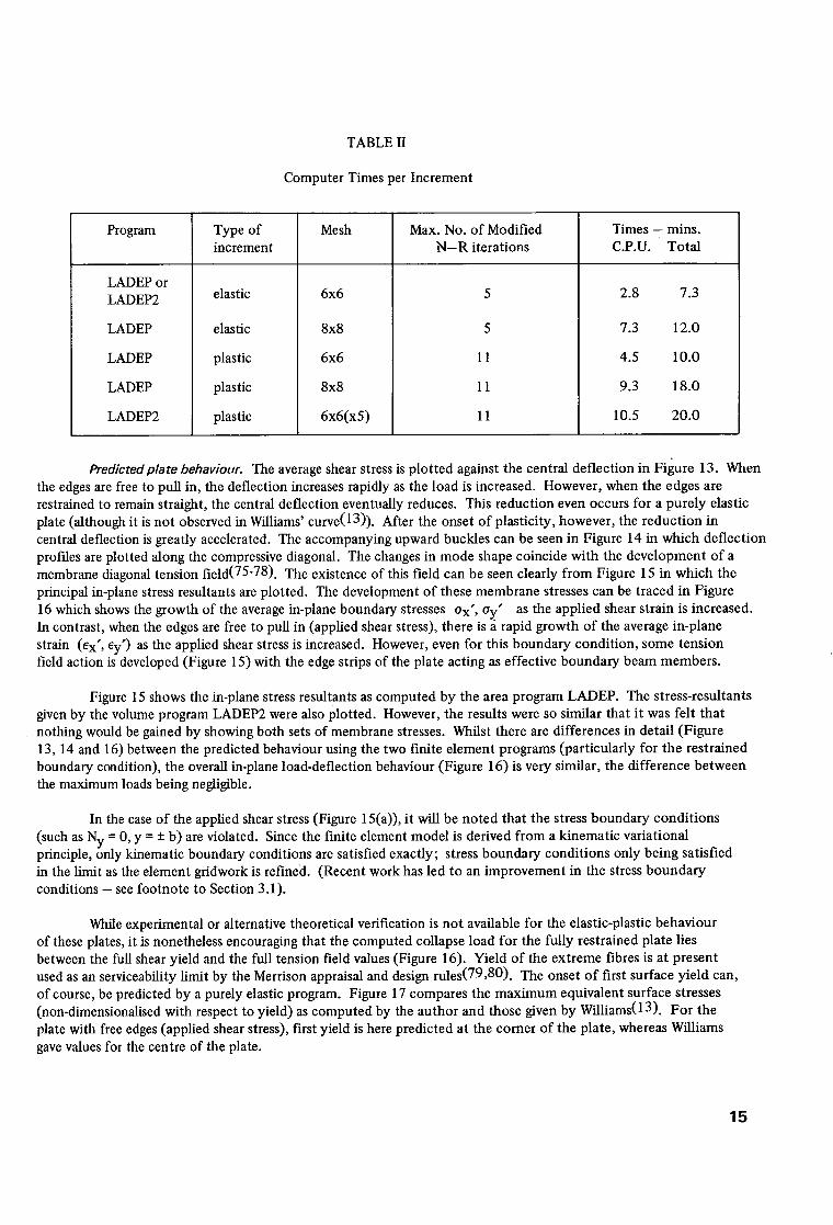
TABLE II
Computer Times per Increment
Program
LADEP or LADEP2
LADEP
LADEP
LADEP
LADEP2
Type of increment
elastic
elastic
plastic
plastic
plastic
Mesh Max. No. of Modified N - R iterations
6x6
8x8
6x6
8x8
6x6(x5)
Times - mins. C.P.U. Total
2.8 7.3
7.3 12.0
4.5 10.0
9.3 18.0
10.5 20.0
5
5
11
11
11
Predicted plate behaviour. The average shear stress is plotted against the central deflection in Figure 13. When the edges are free to pull in, the deflection increases rapidly as the load is increased. However, when the edges are restrained to remain straight, the central deflection eventually reduces. This reduction even occurs for a purely elastic plate (although it is not observed in Williams' curve(13)). After the onset of plasticity, however, the reduction in central deflection is greatly accelerated. The accompanying upward buckles can be seen in Figure 14 in which deflection profiles are plotted along the compressive diagonal. The changes in mode shape coincide with the development of a membrane diagonal tension field(75-78). The existence of this field can be seen clearly from Figure 15 in which the principal in-plane stress resultants are plotted. The development of these membrane stresses can be traced in Figure 16 which shows the growth of the average in-plane boundary stresses Ox', Oy" as the applied shear strain is increased. In contrast, when the edges are free to pull in (applied shear stress), there is a rapid growth of the average in-plane strain (ex', ey') as the applied shear stress is increased. However, even for this boundary condition, some tension field action is developed (Figure 15) with the edge strips of the plate acting as effective boundary beam members.
Figure 15 shows the in-plane stress resultants as computed by the area program LADEP. The stress-resultants given by the volume program LADEP2 were also plotted. However, the results were so similar that it was felt that nothing would be gained by showing both sets of membrane stresses. Whilst there are differences in detail (Figure 13, 14 and 16) between the predicted behaviour using the two finite element programs (particularly for the restrained boundary condition), the overall in-plane load-deflection behaviour (Figure 16) is very similar, the difference between the maximum loads being negligible.
In the case of the applied shear stress (Figure 15(a)), it will be noted that the stress boundary conditions (such as Ny = 0, y = -+ b) are violated. Since the finite element model is derived from a kinematic variational principle, only kinematic boundary conditions are satisfied exactly; stress boundary conditions only being satisfied in the limit as the element gridwork is refined. (Recent work has led to an improvement in the stress boundary conditions - see footnote to Section 3.1).
While experimental or alternative theoretical verification is not available for the elastic-plastic behaviour of these plates, it is nonetheless encouraging that the computed collapse load for the fully restrained plate lies between the full shear yield and the full tension field values (Figure 16). Yield of the extreme fibres is at present used as an serviceability limit by the Merrison appraisal and design rules(79,80). The onset of first surface yield can, of course, be predicted by a purely elastic program. Figure 17 compares the maximum equivalent surface stresses (non-dimensionalised with respect to yield) as computed by the author and those given by Williams(13). For the plate with free edges (applied shear stress), first yield is here predicted at the corner of the plate, whereas Williams gave values for the centre of the plate.
15

5.2.2 Plate with intermediate restraint. Whilst the previous examples have demonstrated that the ultimate load of plates in shear is highly dependent on their boundary conditions, the idealised boundary conditions that were investigated are seldom met in practise. A more realistic restraint involves the interaction of a web with bounding flanges. Such an interaction has been extensively studied for plate girders(75-78) and is at present the subject of considerable research effort in relation to box girders. Figure 18 shows details of a plate girder tested by Rockey et al(81) which had thin flanges with 'properties similar to those encountered in box girder construction'.
Idealisation. The area program LADEP was used to analyse the girder and in the initial analysis, a coarse 6x7 mesh was employed (Figure 18). Later, a more refined 8x9 mesh was used. This mesh incorporated smaller elements near the flanges, the mesh division in the y direction being 57.1mm; 6x76.2mm, 57.1mm; while a regular 9x94.5mm mesh was adopted in the x direction. The flanges, with their stiffeners (Figure 18) were idealised as line elements with the same total area as the flange plus flange stiffeners. The flange is thin so that the second moment of area about its centroid is negligible. However, the flange stiffeners have a significant second moment of area with respect to the centre of the flange, so that the adopted idealisation is not exact. For the analysis, the plate was 'loaded' by applying constant (v) deflections in the y direction (Figure 18) along the centre line of the web plate. This should give a reason- able representation of the effect of the wing-plate loading.
Of the various girders tested by Rockey et al(81), plate girder 1 AS1.5 was chosen for the analysis since the behaviour of this girder is described in coasiderable detail. Unfortunately, however, the plates in girder 1 AS1.5 had the largest initial imperfections (6 o = 11.9mm or 8_0 = 3.8). It has previously been mentioned that the present theory
t aw aw
is valid for a x , ay "~ 1 and it was feared (probably wrongly, see Section "Numerical details') that the large initial
imperfections of the plates in this girder might lead to a violation of this criterion. For this reason, a slightly smaller
initial imperfection (6 o = 10.2mm or 8o = 3.25) was considered for the analysis (using a sinusoidal wave form). This • t small difference in initial imperfectlon would be unlikely to have any significant effect on the behaviour of a real plate.
Dowling et al(82), describing a series of tests on rectangular stiffened steel box girders, detected 'no significant variation in the capacity of comparable web panels as a consequence of varying magnitudes of residual stresses and out-of-plane deformations in the panels'.
Numerical details. The convergence criteria initially adopted were very similar to those described in Section "ldealisation" in relation to the previous examples on plates in shear. However, somewhat larger load (strictly deflection) steps were applied in the present analysis and, possibly for this reason, difficulty was experienced in satisfying the incremental convergence criterion as the applied loads exceed ninety three percent of the eventual maximum load. For this reason the ten percent restriction on the maximum incremental out-of-plane deflection change was relaxed to twenty percent. The change of total deflection (using either the maximum out-of-plane deflection or the Euclidean norm) was still well within the one percent limit. Stricklin et al(56) describe similar convergence problems for the analysis of a shell of revolution. They overcame the problem by using sub-increments for the treatment of plasticity(44). Such an approach is currently being ctmsidered for the author's programs.
Concern about the magnitude of the slopes, ~ and a___w, in relation to the adopted Lagrangian formulation
has already been mentioned. In practise, the maximum°X slopes°V~hat were computed at the maximum load were . _ _ + 3 ~aw~2~ about 0.1 Since the theory adopted has assumed 1 = - a 2 w whereas a more exact expression is 1 = - a 2 w (1 ~'~xx" "'
R ax 2 R ax 2
the slopes of 0.1 imply a 1.5 percent error in the curvature terms. Such an error should not be of any significance; indeed it is probable that the reduction of the actual initial imperfection was an unnecessary precaution. Since, however, the deflections increase rapidly beyond the maximum load, errors due to the fixed co-ordinate system may well become significant in the post-collapse range.
Predicted behaviour. Figure 19 shows the load-deflection behaviour computed for the girder. The predicted collapse load is twelve percent below the experimental value. Also shown in Figure 19 is the collapse load derived by means of the Rockey-Skaloud temion field model(76). This approach involves a semi-emperical calculation which uses a coUapse mechanism to estimate the maximum load. The method is strongly dependent on the plastic moment of the 'bounding member' , which consists of the flange (and associated stiffeners) acting with an empirical depth of web. In the current example the eccentricity of the flange stiffener contributes appreciably to the plastic moment of the 'edge member' . It is significant that if only the area, and not the eccentricity, of the flange stiffener is included
1 6

in the calculation for the plastic moment (in a similar fashion to the idealisation of the flange adopted for the f'mite element analysis), then the predicted load is reduced below the previous tension field value by some fifteen percent. Strain gauges were not positioned on the stiffener outstands so it is not possible to assess the significance of the bending stiffness of the flange stiffeners. The bending stiffness (in the plane of the plate) of boundary line elements has not be included in the present fmite element programs. The degrees of freedom necessary to make the relevant plate-beam connection are not available with the present bi-linear in-plane shape functions. Various authors(83-85) have, however, derived special in-plane plate elements to deal with this connection. This work has been related to linear shear wall structures, but there is no reason why the relevant shape functions should not be incorporated in the present non-linear analysis.
The out-of-plane deflection prof'des have been plotted along the compressive diagonal of the web plate in Figure 20 (6x7 mesh). Also shown in the same Figure is a graph depicting how the maximum 'pull-in' deflections on the top and bottom flanges vary with increasing load. Describing a series of photographs of girder 1 AS1.5, taken in the neighbourhood of the failure load, Rockey et al(81) write ' the flanges having been relatively straight when the ultimate load was first reached ........ the gross deformations occurring in the very last stages of the test'. This description is in agreement with the behaviour depicted in Figure 20.
The computed principal in-plane stress resultants (6x7 mesh) are shown in Figure 21. The yielding diagonal tension field is clearly evident. It should be noted that yield, as indicated by the circles in Figure 21, relates to full- section yield as defined by Ilyushin's criterion. Plasticity is therefore dependent on the bending moments as well as the in-plane stress resultants. Tension field theory uses a collapse mechanism involving the tensile yielded zone as well as hinges in the 'bounding members' in the region of points E and F (Figure 21). Although it is clear from Figure 20 that there is a sudden loss of stiffness in the 'edge members' as the flanges pull in, the computed stresses (in-plane) in the flanges have not reached compressive yield (as would be necessary for the formation of the hinges). It is the author's contention that the rapid pull-in of the (initially top) 'bounding member ' is initiated, not by yield in the flange, but by an inward buckling of the bent 'member'. This buckling is due to the combined action of the lateral load caused by the tension field and the in-plane load resulting from both the tension field and the overall bending of the girder (See the simple model in Figure 22). Further application of load (or strictly of deflection) would eventually lead to compressive yield of the flange. It is quite possible, however, that the resulting mechanism would only be formed after a significant drop-off of load.
6. CONCLUSIONS
Finite element methods have been presented for the large deflection elastic-plastic analysis of plates. The methods involve either a volume integration using yon Mises' yield criterion, or an area integration using Ilyushin's yield criterion which assumes a sudden plastification through the plate depth. The latter approach, is considerably more economical than the former and has been shown to give very similar answers.
The computer programs have been checked against classical solutions for the large deflection behaviour of elastic plates and good agreement has been found. For elastic-plastic problems, involving the instability of imperfect plates, a satisfactory correlation has been observed with experimental results and alternative theoretical solutions.
The programs may be used to investigate the effects of different initial imperfections, boundary restraints and residual stresses on the collapse behaviour of plate panels. Such parametric studies would be more economically undertaken using the 'area program' (LADEP). For each class of problem, a single analysis could be performed using the more exact 'volume program' (LADEP2). This would serve as a check on the applicability of Ilyushin's yield criterion.
Whilst the computer programs may be used in their present form, there is scope for improvement. In particular, further consideration could be given to the derivation of a suitable criterion for the optimum size of increment in relation to elastic-plastic problems. The programs could also be ammended to include eccentric stiffeners.
17

7. A C K N O W L E D G E M E N T S
This work was carried out in the Bridge Design Division (Head of Division Dr. G.P. TiUy) of the Structures Department. The author would like to take this opportunity of acknowledging, with gratitude, the help and encouragement of Dr. L.C.P. Yam (Head of Structural Analysis Section). In addition thanks are due to Dr. P.C. Das for helpful discussions.
1.
2 .
.
4 .
.
.
.
.
.
1 0 .
1 1 .
1 2 .
1 3 .
1 4 .
1 5 .
1 6 .
18
8. R E F E R E N C E S
LEVY, S. Bending of rectangular plates with large deflection. NACA Technical Note 846, 1942.
YAMAKI, N. Postbuckling behaviour of rectangular plates with small initial curvature loaded in edge compression. Journal of Applied Mech., 26, 3, Sept. 1959, pp 407--414.
COAN, J.M. Large deflection theory for plates with small initial curvature loaded in edge compression. Journal of Applied Mech., 18, 2, June 1951, pp 143-151.
WALKER, A.C. The postbuckling behaviour of simply supported square plates. Aeronautical Quarterly, 20,3, Aug. 1969, pp 203-226.
DAWSON, R.G. and A.C. WALKER. Postbuckling of geometrically imperfect plates. Journal of Struct. Div., Proc. A.S.C.E., Jan. 1972, ST1, pp 75-94.
BASU, A.K. and J.C. CHAPMAN. Large deflection behaviour of transversely loaded rectangular orthotropic plates. Proc. Instn. Civ. Engrs., Vol. 35, Sept. 1966.
ALAMI, B. Large deflection of elastic plates under patch loading. Proc. Journal of Struct. Div., Proc. A.S.C.E., Vol. 98, No. ST11, Nov. 1972, pp 2567-2586.
BHAUMIK, A.K. and J.T. HANLEY. Elasto-plastic plate analysis by finite differences. Journal of Struct. Div., Proc. A.S.C.E., Oct. 1967, pp 279-294.
YAM, L.C.P. and P.C. DAS. Elastoplastic analysis of reinforced concrete slabs - some implications of limit state design. Proc. Int. Conf. on Developments in Bridge Design and Construction, Cardiff, 1971, edited by K.C. Rockey, J.L. Bannister and H.R. Evans, pub. Crosby Lockwood, London, pp 144-160.
LIN, T.H., S.R. LIN and B. MAZELSKY. Elastoplastic bending of rectangular plates with large deflection. Journal of Applied Mech., Dec. 1972, pp 978-982.
LIN, T.H. and E. HO. Elastoplastic bending of a thin rectangular plate. Journal of Eng. Mech. Div., Proc. A.S.C.E., Vol.94, EMI, 1968, pp 199-210.
RUSHTON, K.R. Large deflection of plates with unsupported edges. Journal of Strain Analysis, Vol.7, No.l, 1972, pp 44--53.
WILLIAMS, D.G. Some examples of the elastic behaviour of initially deformed bridge panels. Civil Eng. & Pub. Wks. Rev., Oct. 1971, pp 1107-1112.
WALKER, A.C. A non-linear finite element analysis of shallow circular arches. Int. Journal of Solids & Structures, 5, 1969, pp 97-107.
THOMPSON, J.M.T. and A.C. WALKER. A non-linear perturbation analysis of discrete structural systems. Int. Journal of Solids & Structures, 4, 1968, pp 757-767.
MOXHAM, K.E. Theoretical prediction of the strength of welded steel plates in coaapression. Cambridge University Report No. CUED]C -- Struct/TR2, 1971.
17. GRAVES SMITH, T.R. The effect of initial imperfections on the strength of thin-walled box columns. Int. Journal of Mech. Sci., Vol.13, 1971, pp 911-925.
18. GRAVES SMITH, T.R. The postbuckling behaviour of a thin-walled box beam in pure bending. Int. Journal of Mech. Sci., Vol.14, No.l, Nov. 1972, pp 711-722.
19. TURNER, M.J., E.H. DILL, H.C. MARTIN, and R.J. MELOSH. Large deflection of structures subject to heating and external loads. Journal of Aerospace Sciences, Vol.27, Feb. 1960.
20. GALLAGHER, R.J. and J. PADLOG. Discrete element approach to Structural stability. Am.Inst. of Aero. and Astro. Journal, Vol.1, No.6, June 1963, pp 1437-1439.
21. KAPUR, W.W. and B.J. HARTZ. Stability of plates using the finite element method. Journal of Eng. Mech. Div., Proc. A.S.C.E., Vol. 92, EM2, April 1966.
22. GALLAGHER, R.J., R.A. GELLATLY, J. PADLOG and R.H. MALLET. A discrete element procedure for thin shell instability analysis. Am. Inst. of Aero. & Astro. Journal, Vol.5, No.I, Jan. 1967, pp 138-145.
23. HOLAND, I. and T. MOAN. The finite element in plate buckling. Finite dement methods in stress analysis edited by Holand and Bell, Tapir, 1969.
24. ARGYRIS, J.H. Recent advances in matrix methods of structural analysis. Pergamon press, 1964.
25. ARGYRIS, J.H. Continua and discontinua. Proc. Conf. Matrix Methods in Struct. Mech., Air Force Inst. of Tech., Wright Patterson Air Force Base, Ohio, Oct. 1965.
26. YANG, T.Y. Finite displacement plate flexure by the use of matrix incremental approach. Int. Journal of Numerical Meth. in Eng., 4, 1972, pp 415-432.
27. MALLET, R.H. and P.V. MARCEL. Finite element analysis of non-linear structures. Journal of Struct. Div., Proc. A.S.C.E., Vol. 94, No. ST9, Sept. 1968, pp 2081-2105.
28. MARCAL, P.V. Finite element analysis of combined problems of non-linear material and geometric behaviour. Proc. American Soc. Mech. Eng. Conf. on Computational approaches in Applied Mech., June 1969.
29. DUPIUS, G.A., H.D. HIBBIT, S.F. MCNAMARA and P.V. MARCAL. Non-linear material and geometric behaviour of shell structures. Computers and Structures, Vol.1, 1971, pp 223-239.
30. ODEN, J.T. Numerical formulation of non-linear elasticity problems. Journal of Struct. Div., Proc. A.S.C.E., Vol. 93, No. ST3, Paper 5290, June 1967.
31. SCHMIT, F.K., F.K. BOGNOR and R.L. FOX. Finite deflection structural analysis using plate and shell discrete elements. Am. Inst. Aero. and Astro. Journal, Vol.6, No.5, 1968, pp 781-791.
32. MALLET, R.H. and L.A. SCHMIT. Non-linear structural analysis by energy search. Journal of Struct. Div., Proc. A.S.C.E., Vol. 93, No. ST3, June 1967, pp 221-234.
33. BREBBIA, C. and J. CONNOR. Geometrically non-linear finite element analysis. Journal of Eng. Mech. Div., Proc. A.S.C.E., Proc. Paper 6516, April 1969.
34. MURRAY, D.W. and E.L. WILSON. Finite element large deflection analysis of plates. Journal of Eng. Mech. Div., Vol. 95, No. EM1, Feb. 1969, pp 143-165.
35. MURRAY, D.W. and E.L. WILSON. Finite element postbuckling analysis of thin elastic plates. American Inst. of Aero. & Astro, Jrnal, Vol.7, 1969, pp 1915-1930.
19

36.
37.
38.
39.
40.
41.
42.
43.
4.
45.
46.
47.
48.
49.
50.
51.
52.
ODEN, J.T. Finite element applications in non-linear structural analysis. Proc. Conf. on Finite Element Meth., Vanderbilt University, Tennessee, Nov. 1969.
ZIENKIEWlCZ, O.C. The finite element in engineering science. McGraw-Hill, London, 1971.
HAISLER, W.E., J.E. STRICKLIN and F.J. STEBBINS. Development and evaluation of solution procedures for geometrically non-linear structural analysis by the direct stiffness method. A.I.A.A./A.S.M.E. 12th Structures, Structural Dynamics and Materials Conf., Anaheim, California, April 1971.
POPE, G. A discrete element method for analysis of plane elastic-plastic stress problems. Royal Aeronautical Establishment TR SM 65-10, 1965.
MARCAL, P.V. and I.P. KING. Elastic-plastic analysis of two dimensional stress systems by the finite element method. Int. Journal of Mech., Sci., Vol.9, No.3, 1967, pp 143-155.
YAMADA, Y., N. YOSHIMURA and T. SAKURAI. Plastic stress-strain matrix and its application for the solution of elasto-plastic problems by the finite element method. Int. Journal of Mech. Sci., 10, 1968, pp 343-354.
ZIENKIEWlCZ, O.C., S. VALL1APAN and I.P. KING. Elasto-plastic solutions of engineering problems. Initial stress, finite element approach. Int. Journal of Numerical Meth. in Eng., 1, 1969, pp 75-100.
MARCAL, P.V. Finite element analysis with material non-linearities - theory and practise. Recent Advances in Matrix Methods of Structural Analysis and Design, edited by R.H. Gallagher, Y. Yamada and J. Tinsley Oden, Pub. The University of Alabama Press, 1971, pp 257-282.
NAYAK, G.C. and O.C. ZIENKIEWICZ. Elasto-plastic stress analysis. A generalisation for various con- stitutive relationships including strain softening. Int. Journal for Numerical Meth. in Eng., Vol.5, 1972, pp 113-135.
MARCAL, P.V. and R.H. MALLET. Elasto-plastic analysis of plates by the finite element method. Proc. A.S.M.E. Winter Annual Meeting Paoer 68-WA3PVB-10, Dec. 1968.
ANG, A.H.S. and L.A. LOPEZ. Discrete model analysis of elastic-plastic plates. Journal of Eng. Mech. Div., Proc. A.S.C.E., Vol. 94, No. EM1, Feb. 1968, pp 271-293.
ARMEN, H., A.B. PIFKO, H.S. LEVINE, and G. ISAKSON. Plasticity, Chapt. 8 of Finite Element Techniques in Structural Mechanics, edited by H. Tottenham and C. Brevvia, Southampton University Press, England, 1970.
WHANG, B. Elasto-plastic orthotropic plates and shells. Proc. Symp. on Application of Finite Element Methods in Civil Engineering, School of Eng. Vanderbilt University, A.S.C.E., 1969, pp 481-516.
BELYTSCHKO, T. and M. VELEBIT. Finite element method for elastic plastic plates. Journal of Eng. Mech. Div., Proc. A.S.C.E., EM1, Feb. 1972, pp 227--242.
MARCAL, P.V. and W.R. PILGRIM. A stiffness method for elastic-plastic shells of revolution. Journal of Strain Analysis, Vol.1, No.4, 1966, pp 339-350.
TERAZAWA, K.,Y. UEDA and M. MATSUISHI. Elasto-plastic buckling of plates by finite element method. A.S.C.E. Annual Meeting and National Meeting on Water Resources Eng., New Orleans, La., Feb. 1969, Paper 845.
HARRIS, H.G. and A.B. PIFKO. Elasto-plastic buckling of stiffened rectangular plates. Proc. Symp. on Application of Finite Element methods in Civil Eng., School of Eng. Vanderbilt University, A.S.C.E., 1969, pp 207-253.
20
53. MURRAY, D.W. and E.L. WILSON. An approximate non-linear analysis of thin plates. Proc. Air Force 2nd Conf. on Matrix Meth. in Struct. Mech., Wright-Patterson Air Force Base, Ohio, Oct. 1968.
54. MARCAL, P.V. Large deflection analysis of elastic-plastic shells of revolution. American Inst. of Aero. & Astro. Journal, 8, 1970, pp 1627-1634.
55. GERDEEN, J.C., F.A. SIMONEN, and D.T. HUNTER. Large deflection analysis of elastic-plastic shells of revolution. A.I.A.A./A.S.M.E. 11 th Structures, Structural Dynamics and Materials Conf., Denver, Colorado, April 1970, pp 239-249.
56. STRICKLIN, J.A., W.E. HAISLER and W.A. VON RIESEMANN. Computation and solution procedures for non-linear analysis by combined finite element - finite difference methods. Computers and Structures., Vol.2, Dec. 1972, pp 995-974.
57.
58.
SABIR, A.B. and A.C. LOCK. The application of finite elements to the large deflection geometrically non- hnear behaviour of cylindrical shells. Proc. Int. Conf. on Variational Meth. in Eng., Dept. of Civil Eng., Southampton University, England, Sept. 1972~ Session VII, pp 67-76.
KHAN, A.Q., A.A. MUFTI and P.J. HARRIS. Post-buckling of thin plates and shells. Proc. Int. Conf. or? Variational Meth. in Eng., Dept. of Civil Eng., Southampton University, England, Sept. 1972, Session VII pp 55-66.
59. BREBBIA, C. and H. TOTTENHAM. Shells, Chapt. 6 of Finite Element Techniques in Structural Mechanics, edited by H. Tottenham and C. Brebbia, Southampton University Press, England, 1970.
60. STOWELL, E.Z. A unified theory of plastic buckling of columns and plates. NACA Report No. 898, 1948.
*61. ILYUSHIN, A.A. The elasto-plastic stability of plates. NACA Technical Memorandum No. 1188, Dec. 1947.
62. POWELL, M.J.D. An iterative method for finding stationary values of a function of several variables. The Computer Journal, Vol.5, 1966, p 147.
*63. ILYUSHIN, A.A. Plasticitd, Editions Eyrolles, Paris, 1956.
64. MASSONET, C. General theory of elasto-plastic membrane-plates. Engineering Plasticity, edited by J. Heyman and F.A. Leakie, Cambridge University Press, 1968, pp 443-473.
65. ZIENKIEWICZ, O.C. and Y.K. CHEUNG. The finite element method for the analysis of elastic isotropic and orthotropic slabs. Proc. Instn. of cir. Engrs., 28, 1964, pp 471-488.
66. IRONS, B.M. Numerical integration applied to finite element methods. Conf. on Use of Digital Computers in Struct. Eng., University of Newcastle, 1966.
67. NAYAK, G.C. and O.C. ZIENKIEWlCZ. Note on the 'alpha-constant' stiffness method for the analysis of non-linear problems. Int. Journal for Numerical Meth. in Eng., 4, 1972, pp 579-582.
68. ZIENKIEWlCZ, O.C. and B.M. IRONS. Matrix iteration and acceleration processes in finite element problems of structural mechanics. Chapt.9 of Numerical Meth. for non-linear algebraic equations, edited by P. Rabinowitz, Gordon and Breach, 1970.
69. MARGUERRE, K. Zur Theorie der gekrummten platten formanderung. Proc. Fifth Int. Congress of App. Mech., Cambridge, 1938, pp 93-101.
70. MOXHAM, K.E. Buckling tests on individual welded steel plates in compression. Cambridge University Report No. CUECD/C-Struct./TR3, 1971.
* Sometimes spelt ILIOUCHINE
21
71.
72.
73.
74.
75.
76.
77.
78.
79.
80.
81.
82.
83.
84.
85.
86.
DWIGHT, J.B. Collapse of steel compression panels. Proc. Int. Conf. on Developments in Bridge Design and Construction, edited by K.C. Rockey, J.L. Bannister and H.R. Evans, pub. Crosby Lockwood, London, 1971, pp 519-539.
GREGORY, M. Elastic instability, pub. E & F N Spon. Ltd., London, 1967.
DWIGHT, J.B. and K.E. MOXHAM. Welded steel plates in compression. The Structural Engineer, Vol. 47, No.2, Feb. 1969, pp 49-66.
BULSON, P.S. The Stability of flat plates, pub. Chatto and Windus, London 1970.
WAGNER, H. Flat sheet metal girder with very thin metal web. U.S. Nat. Advisory Council for Aeronautics, NACA Tech. Memo's 604, 605 and 606, Washington, 1931.
ROCKEY, K.C. and M. SKALOUD. The ultimate load behaviour of plate girders loaded in shear. The Structural Engineer, Vol.50, No.l, Jan., 1972, pp 29--47.
OSTAPENKO, A., C. CHERN and S. PARSANEJAD. Ultimate strength design of plate girders. Proc. Int. Conf. on Developments in Bridge Design and Construction, Cardiff, 1971, edited by K.C. Rockey, J.L. Bannister and H.R. Evam, pub. Crosby Lockwood,London, pp 505-518.
CALLADINE, C.R. A plastic theory for collapse of plate girders under combined shearing force and bending moment. Cambridge University Report No. CUED/C. Struct/TR.29, 1972.
COMMITTEE OF INVESTIGATION INTO THE DESIGN AND ERECTION OF STEEL BOX GIRDER BRIDGES. Appendix A - Interim design appraisal rules, Dept. of the Environment Sept. 1971.
COMMITTEE OF INVESTIGATION INTO THE DESIGN AND ERECTION OF STEEL BOX GIRDER BRIDGES. Steel box girder bridge design rules. Feb. 1973.
ROCKEY, K.C., H.R. EVANS and D.M. PORTER. The ultimate load capacity of stiffened webs subject to shear and bending. Proc. Int. Conf. on Steel Box Girder Bridges, Instn. of civ. Engrs., London, Feb. 1973, Paper No.4.
DOWLING, P.J., S. CHATTERJEE, P.A. FRIEZE and F.M. MOOLANI. The experimental and predicted collapse behaviour of rectangular stiffened steel box girders. Proc. Int. Conf. on Steel Box Girder Bridges, Instn. of cir. Engrs., London, Feb. 1973.
OAKBERG, R.G. and W. WEAVER. Analysis of frames with shear walls by finite elements. Proc. Symp. on Application of Finite Element methods in Civil Eng., School of Eng. Vanderbilt University, A.S.C.E., 1969, pp 567--607.
MACLEOD, I.A. New rectangular finite element for shear wall analysis. Journal of Struct. Div., ASCE, Vol.95, No. ST3, March 1969, pp 399--409.
BUTLIN, G.A. and C.M. MCMILLAN. An improved finite element for analysis of plane coupled shear walls. Civ. Eng. and Public Works. Review, Dec. 1971, pp 1299-1303.
MELOSH, R.J. Manipulation errors in f'mite element analysis. Recent Advances in Matrix Methods of Struct. Analysis and Design, edited by R.H. Gallagher, Y. Yamada and J. Tinsley Oden, pub. The University of Alabama Press, 1971, pp 857-876.
22
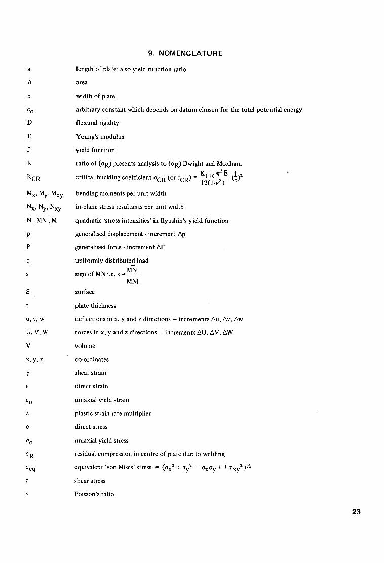
a
A
b
c o
D
E
f
K
KCR
Mx, My, Mxy
Nx, Ny, Nxy
N , M N ,M
P
P
q
s
S
t
U, V, W
U,V,W
V
x, y, z
"r
c
4 o
o
o o
o R
aeq
T
9. NOMENCLATURE
length of plate; also yield function ratio
area
width of plate
arbitrary constant which depends on datum chosen for the total potential energy
flexural rigidity
Young's modulus
yield function
ratio of (OR) presents analysis to (OR) Dwight and Moxham 7r 2 E KCR (_~)2 critical buckling coefficient oCR (or TCR ) = 12(1.v2)
bending moments per unit width
in-plane stress resultants per unit width
quadratic 'stress intensities' in Ilyushin's yield function
generalised displacement - increment Ap
generalised force - increment AP
uniformly distributed load
MN sign of MN i.e. s =
IMNI
surface
plate thickness
deflections in x, y and z direct ions - increments Au, Av, Aw
forces in x, y and z directions - increments AU, AV, AW
volume
co-ordinates
shear strain
direct strain
uniaxial yield strain
plastic strain rate multiplier
direct stress
uniaxial yield stress
residual compression in centre of plate due to welding
equivalent 'yon Mises' stress = (Ox 2 + Oy 2 -- OxOy + 3 ~-xy2)½
shear stress
Poisson's ratio
2 3

¢
8o
total potential energy -- increment A(I)
initial imperfection at centre of a buckle measured from initial median plane
9.1 Subscripts
A
CR
i
o
P
t
V
z
'Area approach'
critical
in-plane
out-of-plane
plastic
total
'Volume approach'
at depth z
9.2 Superscripts
p f
refers to a quantity non-dimensionalised with respect to the value of that quantity at yield
refers to the extreme fibre of the plate
9.3 Vectors
{x}
<w) <w} <u}
stresses--increments {Ao)
strains-increments ( A e )
linear in.plane strains with ( e } T = (aUax , ay,aV aUay + b--x av )
non-linear in-plane strains with (+}Te = ( ½ (aw~2kax/' ½ (aw~2kay/' (-~-)aw (_~)
generalised stress resultants - increments ( AN } , ( AM )
curvatures with { x ) T = { a~Wax 2 , a2way 2 ' -2a2W-axay t -increments {AX}
slopes - increments <AS)
generalised nodal out-of-plane displacements - increments (Aw)
generalised nodal out-of-plane forces -- increments { AW)
nodal in-plane deflections - increments Av
AU nodal in-plane forces - increments ( AV
generalised nodal displacements - increments (Ap]"
generalised nodal forces - increments {AP)
generalised internal nodal forces
linear functions of generalised strain increments
non-linear functions of generalised strain increments
2 4

9.4 Matrices
[B], [F], [H]
[El
[E*]
[C*], [D*], [cd]
[KE]
[TS]
[+]z +
[N]
9.5 Programs
SHAPE
LADE
LADEP
LADEP2
matrices derived by differentiating shape functions
modular matrix (3 x 3)
tangential elasto-plastic modular matrix
tangential elasto-plastic modular matrices relating to generalised stress resultants
tangent stiffness matrix
total slopes
stresses at level z
in-plane stress resultants
program to give initial distribution of deflections, stresses and strains
large deflection elastic program
large deflection elasto-plastic program using Ilyushin's yield criterion - 'area approach'
large deflection elasto-plastic program using yon Mises' yield criterion - 'volume approach'
10. APPENDIX 1
Derivation of tangential elasto-plastic matrices for 'area approach"
Ilyushin(63) has derived the following approximate yield criterion for a shell:
4sM-N 16 f - + + - - ~<1
- - O0 2 t 20o 2 ~/3 t a o o 2 t 4 .................................. (10.1)
where N, MN and M are quadratic 'stress intensities' given by:
and s = ,,17_?
= Nx 2 + Ny z - N x N y + 3Nxy 2
= Mx 2 + My 2 - M x M y + 3 M x y 2
M-N -- M x N x + M y N y - ½ M x N y - ½ M y N x + 3 M x y N x y
fiN IMNI
................................... (10.2)
For plastic flow to take place, the generalised stress resultants must remain on the yield surface and hence
6 f = 0 .................................... (10.3)
From equations (10.1) and (10.2),
{ f n } T . [ A N ) + { f m } T {AM} = 0 ................................... (10.4)
25

where h
{fn }= t~ ~/3-ta - ~ } .................................... (10.5)
{fm }= /~-ta ~ + t'- ~-
To avoid the discontinuity in the partial derivatives of f as MN * 0, s is made zero when MN is very small *.
Assuming that equation (10.1) may be treated as a plastic potential such that the plastic strain rates are proportional to its partial derivatives,
{Aep} = X{fn} } .................................. (10.6)
{AXp}= k{fm)
where k is a positive scalar. The elastic incremental generalised stress-strain laws are(64) assumed to be Hookean in nature(64):
{AN} = {AM} = ~ tat rE]rE] {{/Net}{{/NXt} ---- ((AeP}}AXp}} } ................................... (10.7)
Substituting into equation (10.7) from equations (10.6) and making use of equation (10.4) gives the following expression for the plastic strain rate multiplier k.
x = 1 ( t ~ f n l T [ E l Z / N ' t t + L ~ J ~ J 12 ~ ' " " ~ ~ ~ f m l T [ E l ( ~ X t t ) . . . . . . . . . . . . . . . . . . . . . . . . . . " . . . . . . . . ( 1 0 . 8 ) (m+n)
where n= t m = - - ta 12 { fn {fm} T } T [E] { [E] fn } (fm} ~ ................................... (10.9)
The plastic strain increments may be related to the total strain increments by substituting from equation (10.9) into equations (10.6):
(Aep} = 1 ( t [N] [E]{Aet} + ta [NM] [E] {/NXt}- } t (m-l-n) "~ .................................... (10.10)
t 3 (/NXp} 1 {ttNM]TtE] {Aet} +-i2 [M] [ E ] { ~ t } } (m+n)
where
[ . ] -- {fn} {fay i = { fm} {fro}
(fn} {fm}" ................................... (10.11)
Substitution from equations (10.10) into equations (10.7) leads to the following relationship between the increments of the generalised stress resultants and the increments of total generalised strain:
I 4M-N I * MN is considered to be very small when x/3t a o---~2 < 10 -4
26

where [C*], [D*] and [cd] are the tangential elasto-plastic modular matrices.
They are given by:
[C*]= t [ E ] E [ I ] - t (m+n) [N] [E]~
t 3 [O*]= - ~ [E] Eli] t3
12(m+n) [M] [E l
t 4 [cd] = 12(m+n)" [El [NM] [E l J
................................... (10.12)
................................... (10.13)
11. APPENDIX 2
Computing details
The programs LADEP (which uses the area approach) and LADEP2 (which uses the volume approach) have been written in Fortran IV. All the development and production work was carried on the TRRL ICL System 4/70 computer which implements the Multi-job operating system. The programs occupy 107 K Bytes of core store where each single precision variable occupies four Bytes. The programs are overlaid and disc backing store is used to store the structure stiffness matrix in a banded form. The stiffness equations are solved by means of a modified Cholesky upper-lower triangular de- composition routine. The modification, given by Melosh(86), avoids the necessity of taking square roots, thereby reducing round-off errors. This is particularly important when, as in the present work, single precision word lengths are adopted.
Care has been taken to keep the input data to a minimum and only about twenty cards are required. The programs at present will handle up to a 10 x 10 mesh. Before running the main program, a small program (SHAPE) must be submitted. This program defines the initial deformations, initial stresses, or initial strains. The arrays con- taining this information are generated and written to a disc File which is used as part of the input data to the main program. The primary output to the main programs is by means of a line printer. However, so as to be able to run the programs in stages, arrays are also output to a disc file. An extra Ffie is output half-way (or at a specified point) through the execution. This file may be used as a starting point for a later submission, should problems such as lack of convergence be experienced towards the end of the first run.
Since the computer is operated in a multi-programming mode, the total times for execution will depend on what other use is being made of the machine. The central processor times (CPU times), however, remain constant.
27

O" \ \
\ \
b Ul U')
L.
U3
\ \
\ \
\ \
\ \
\ \
\ \
\ \
\ \
\ \
\ \
\ \
\ \
\ \
\ \
\ \
\ \
\ \
\ \
\ %
\ \
\ \
\ \
\ \
% \
\ \
\ \
\ %
\ \
\ \
\ \
\ \
\ \
E: o I
I i
El
Strain c
Fig. 1. OIAGRAHHATIC REPRESENTATION OF STRAIN ENERGY

(~)or (~
® v
_1 Apply new load
increment Ap
(~or®
Form tangent stiffness
matr ix [KE ]
(!), ® or ®
Reduce equations
I 0 , ® or ®
0
Solve equat ions : up -do te
t o ta l def lect ions
{p}: {p}'{~p} Up-dote total s t resses
(or stress resu l tan ts )
{ . }: {. } .{ ~o}
®.®or @ @
® or® Calculate out-of- balance
Alternative loops
(~ Incremental (~) Incremental plus correct ion for out-of-balance
load from previous increment
(~ NEWTON-RAPHSON i t e r a t i o n (~ Modif ied NEWTON-RAPHSON i t e r a t i o n
Fig. 2. SOLUTION PROCEOURES

t -
O r "
° B . i f ) i
o .N
. . . . . t?
'l 1: ° • / 0 ~- ,~. "-~ ,,-,
, - .1
,-4
\ ~ - - - - - - ~ ]
0 ~0 ~ ~'. o~ 0 oD ~ ~" ~ 0 . . . . . 6 o 6 ~b

I11
I I I I
8 8 b ~
\ <1,
E ---, ®
3 ~ 1.1.1Ul > C3 121
_1 ..J, _1 I
II '
I I
0
I _ _
to
.A v l
0
r~ rn
_ I
u~
m LaJ
to
t
I I
b
r - - ' - ~ i
\ \
\
I I I
~0 ~)
; ~ 3 0 ! ~ O J S S e J ~S ( e l ! S U e ~ ) ~ D D
E 0)
~: E °_
o E
• - - C o o L. - -
+-~ {3.
E t . . - ~
~ W "o ~_ 0) o
,\
<b
I ~J 0
v - - -
14_ I I
0 2
1.1.1 ¢ /~ C) ¢= ~u (M z ¢~
~L I
C ) t ~ I ' "
0 -:z ( n
m
0 " ~ " LD
~ ' - 0
i l l o
I . _
L . n
0 O0
0 (9
0
0 (M
0

, ^ v .
~ t
, < -
m I -
I <l_
+
. m 121
< ~1
E
E r
> ~: 0
E
u' m .~_
¢n 0
x
v
E
E
U
O.E
v v
>-W >a W~ J .J
I
I
x
v
W
.J
i I I F ~ L-
0 ~ (.0 ~ ~ 0 T--"
~): t~-~--~-~)o,~o~ ~o~s
° ~
~ t , J
,,_,, 10
0
o,I
0 P", -~"
o ,~ i ~ -
~I,,, ~ ~ . . - I X
0 .0_ " '
L
0 ¢} u - o ~ l$1 i l l
0 ¢)
I I I I I 0
0 oJ
0
0 CO

3 '2
3 .0
2.8
2-6
2.4
2"2
~02 . 0
.o 1"8 f,,.,.
1"6 ® £,.
1"4 0
o I - • 1.2 > <
1 '0
0"8
0 ' 6
0"4
0"2
0 0
0
,II, .~.
0.2 o. 4 0.6
YAMAKI (classical) } LADE(f ini te element) V= free
YAMAKI'~ ;~v =0 LADE J ~:c
< I I
V=free.or ~v =0 , ~ 3 c
V=free. or b V ~---~ =0
I I I I I I I I 0"8 1"0 1"2 1"4 1"6 1"8 2-0
Central deflection rat io, tOc/t
Fig. 6. IMPERFECT ELASTIC PLATE UNDER IN-PLANE LOAD, CENTRAL DEFLECTION
~ S
¢ I
2"2
( v =0"3)
y(v)
I
2"4
~(u)
I 2.6 2'8
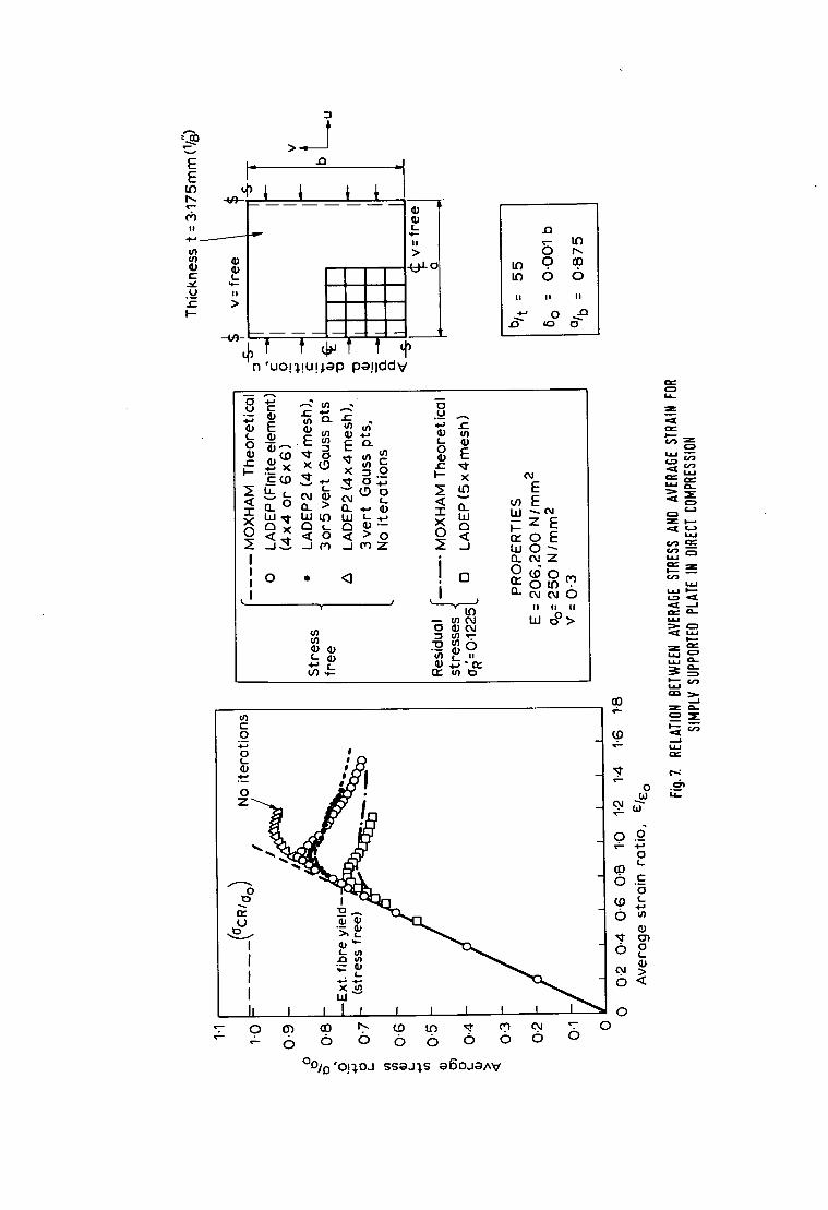
E E
(,,.1 I!
. + . , /
c (_
e- > I - -
3
1 % 7 v
I I
- - - - - - H
- ~ - r - - T - ~ , 0~ n 'uo!~.!U!,l.ap pa! lddV
.D
~- If)
0 ID 0 ~D tD 0 o
I I I I I I
o ~-~
o ~ - . '-' ' -
.-- x ~ 0 I--
~ '-~ ~ ~ ~ ~ ~ E
, . - , ~ > ~ . - x ~ z E 0 0 < r , ' o E < o < , o ~ - ~ , , , o < , ~ . ..
1 o 0 ,, <3 13 n..
• Y ~ II I I I I
g ~ S
c 0 . B
o ,,'A o
-
' ~ ' ' ~ ' -
-
i ~ ' ~ -
It I I I f I t I t t t ~
EL
Z
Z
W
W
&.l. l
Z I ' - - "
e'--"
Z
$.1...I
I,.,=-
0 .--~
o j G u " G-
o.o
L,P 0 ~
o o ~>~ o <
o 0 0"} eO h. (..0 to K," ~ o4 "-:'. 0 • - o (5 0 (5 o 0 o o o
Oo/(]'O!~.OJ SSaJ~.S a6oJaA'v'
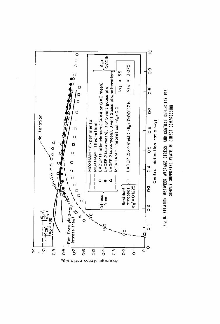
.o
r
0 ° ~
0 (,-
.Q
o z
.<3 <i
<3 <] <]
0 "- 0
0
0
0
0 I O
0
o
O
0
0
E " -
i !
I' I
n 0 0
I - o o~
0
E ~
~ 9 , ~ o X 2 ~ °
, ~ o > _ ( '~ ~ 0
"~ o
._c ,~. ~. ,
Q. n o . ' ~ W bJW~
_ J - J . . J ~
o ~ < 1 i
i J
if)
U')
to 0
I I I I
0 0 o I I 0
I
E
bJ 121
0
" ~ ® o a
o
¢'~ m e¢ 10
0
°li° C ~ 0
0
'" -o <1 \ o
e~ ~o L 8 .
X I L l ' "
I I I I I I I I
o o 6 o o 6 o
°.0/.0 o!~.oJ ssgJ~$ g 6 o J g ^ V
I
0
6
o
- 6
3
- 6 .~ 0 i.
c"
tO . 9 - b V
" 0
¢--
(.)
M
- 6
6
0
0 0
( . 3 Z
l.aJ L , ,
~=_ I,.i.I 1.1,,.I
i , u ' ~ "
Z
..4

E '- ~ E
~ 5 > /
. , , L . . . . ~ - - . ^ " " t t ~ )
' u o ! ~ . ! U h l a p P a ! l d d V
II
>
.Q
0 t ~ 0 0
6 6 I I I I I I
13 r-
~ E L i
o ~ I)
< E E I WL~3
v
i
• ~ , ~ ?,
I1~ m I:)
Od
E LnE
~ z E n - o E
13_ ¢~1
i1: rn
I I I I I I
z
t . ~ z
w
Z ~1~ L u
w z
~ r . o . .
w
°o/D'op, o j ssaJ~,S aROJaAV
0 0'~ cO I'" ~0 LEJ W ~ o~ ~ 0 . , - o o o 6 o (b o 6 o
c~
I 0
i=,,-
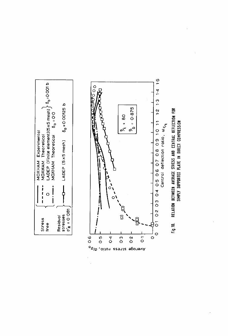
o
~oO ~ U ~ ,,
~E~ "" • ~. ~ ~ ~ ~
LU F-- f" I-- ~
H,
' t :oJ I , i
cO - - ~ O o
.:~, ,,
QD
I I I I
/ i I I I I I
6 0 o o 6 o
°,OLD 'O!~.OJ sSgJ~.$ g6OJg^V
L~
,---
o3 ~
- O L ~ , . ~
0 ~ ~ b . ® ,~
0 ~ . "lJ ¢ - ~ o , -
(bO =-.~
0 = ~ g 0 ~
5 ~
0 0
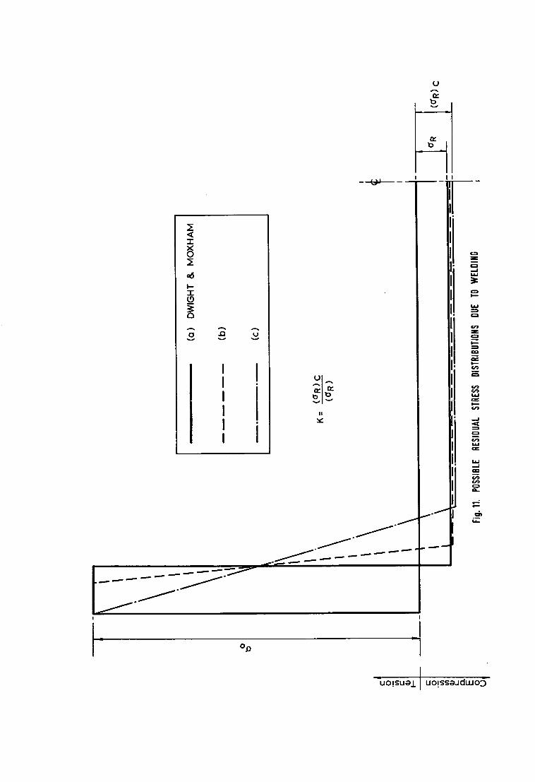
<( T
~r
=6
i A a .Q
n-- n.,
I ! v
j . ~ ' J = m l r ° ~ . . = . . ,~=== =='=" ' ' ~ ~===~ ' = ~ ' " ~ = "
o,0
u A n,.
I
11
~ o ~
Z
0 ..=1 lak,I
o
L--~
¢/=J
0 I - -"
0
LL=
--=1
W
e ~
0
o - - r E
~UO!SU~/ J UO!SS=~JdLuo~-

I
I
~ m
Z
J ~ e.-
" n
<
I _ _ ! E
I J ~ ~ m ~ 0 '~" •
• I I ~11 t l Z
I I "' °° ~ ~ / / E ,~,
~ - , ~ - . J_ ~ E o
- - | I ~ I I I I t l ~ JE)
~ - - - : - _ _ _ - : : _ _ _ - _ ______ _ _ ~ . - - - - . . 1
l \ l l I ' ~---
Z C=3
I
Z
=1--
Z
CZ)
Z
L*
LL I
I ' - -
1,1.1
G O ==P
1,1.1 I '--"
, . .J
o
L L

m E iu(j)
, X 0
I ~
I i..IT, l ' - .., l " "
lu F ~'~
/~ ~ x
i ~ X Xv~
/ < ~.,- ~ m ~- I-~ w l,IW W
/ ~ - - - -
I
iii i t / )
< f
' o
=.
~L p I ~',-,, , ._ ,,, , ~ ~ 0
t J L i n - ' (,.0 ,"~ - •
~ I X ( I ) O ' (D X
I hI ~ ~0 , ^ I ~ ~ XF
I~ ~ - ~ ~ ~ o ~N ~ tm
Uel Iz ~ ,, o I 0,,. r ~ r ~ r,,,'
u ' IG - U u U
I <~ "~ ~ ~ (b " I
I 1 I I I I I I I I I 0
0 ~ ~ .rb ~ ~ ~ ~ ~ -~ 0 ~- ~- 0 d) o (b o 0 <5 o o
.:1. O !~ .oJ S s e J ~ . S .lOOLlc~ e B O J O A V
0
0
O ~ - ~ u
3
_ .~o
- &.~ _.,t~
, .~ C'~I " 0
"dJ.~ L
U
W C ~
L~J mr"
C1~ Z
0
fT.l
~T.

-0 "5
O~
~' 0"5
o 1"0
1.5 i - -
.o 2-0
~ 2"5
~ 3.0
3"5
4-0
I r ~ ~ ,~ .~.~._
1- OEP LADEP 2 I
12"// - \ "3 , . , / I Key no "~' ~"(LADEP) "6"'(LADEP2)
~ \ / / 1 o.o o.o o.o - ~ ",.< / ~' 2 0-28 0-36 0 .3G5 . ~ , . I / 3 0"37 0 " 6 9 0 " 8 5
~ i 4 0 " 4 0 ' " ' O ' " ' 9
"1, / A P P L I E D S H E A R S T R E S S
° '
0 2 :4 5 32
~ 0-51- ~ . , -2. "3 " 9 / 3 / - _ 1 ~ -
A P P L I E D S H E A R S T R A I N
I
Key no ;~' 1 0.0 2 0 .6 3 0.92 4 1-2 5 1.36
z' (LADEP) ~' (LADE'P 2) 0 .0 0 .0
0 . 5 4 6 0 . 5 4 6 0 .817 0 - 8 0 3 0 . 9 0 6
0 . 9 4 5
DIMENSIONS
1: = 7 . 9 4 mm
bit. = 180 mm
Q/b = 1.5 mm
J I-
J
J P-
_ b _
Fig. lL. DEFLECTION PROFILES ACROSS 'COMPRESSIVE' DIAGONAL FOR A PLATE IN SHEAR

i
I !
i'
1, 'V~ . \ ' " x \ x \ /
1 " \ \ / .,. ",x,. "x, Z ,".
- - " " . X
r w w w ~ w r ~
A
. c~ _ o q " ~
~'~, I , I I ! ~ & - .a_ C , ~ X
• ~ ~ ~
e ~ e
=121
u')
B
"o
c
~ o - ~ c ~- "N
- o f f l ~ . -
o
(,'1 ~ . .
. ~ W 1)
0
.¢z
¢ j - j
z
k~a
O . .
ks . .
k - - -
k,.-- ....,J
k,sJ Q~
I
LsJ Z
r L
! Z m
. . . J
C~- m ¢..3 z Q ~ GL.
C2 )
L~
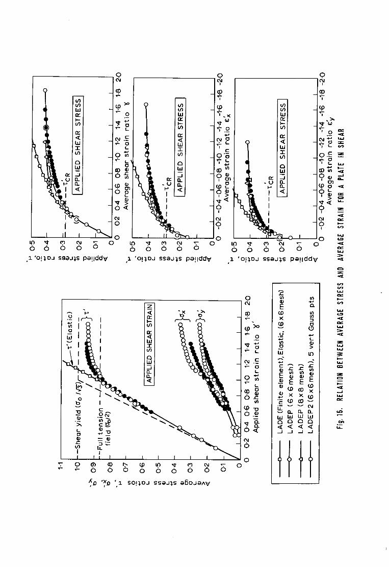
0 d~
( _ 0 9
~o ~ t h~ - • E: "- 0
~ ) ~ _
< ~ ILl --
k U~ _0~
' <
O <
g
I o ~1" ~ ~ ~. 0
0 (5 (5 o o
' o !~ ,oa s~ea~,s P a ! l d d V
0
IZ3
(5
I
"T
'¢,.o
r
0 " ~ "T~
' ° - ~0o
i > ,~1- '< , ,% o:
I
!
I 0 ~1" ~ o~ ~. 0 6 6 6 o
I
I
~ ~ .~ ~- 0 (5 6 6 o o
,~ ' o !~ ,oa ssaa~ ,$ P e ! l d d V ,1 ' o ! ~ , o a s s e a ~ , s P e ! l d d V
0
... -p
I1: < ILl
- 1 "
. - I n
I,. ~-i~ ~. ~
~ o N "
I I " I I I I - I ~
e o = $ "~ ~}
I I
< -~ o
~1 . E
g
m
o . ~
0
0 T 0 (~ ~0 ~ ~ ~ ~ ~ 0~ ~ 0 • - "- 0 0 6 0 6 o 6 0 o
~,D ',xD ',1 so!~,oJ sseJ~,s eSOJeAV
E ~
v (.9 G
o >
~ x x
L O_ I~_ Q_
O a El
....I _ J .. .I _ J
tttt
0
!
T O ,-~
0 t- z
! fm "~J I----
o,®~_ O 3
6 " , > ~ . ~ . < u_ 0 z
,o
o
z
w
eJ~
I.t.J
w
z
I J . I
Z
....I
° ~ U . .

O
(5
< LIJ T
I
I
i d
o b
#-
~- b
7.o_" I -
0 d
. o ~
0 , . ,
- 0 ~
I I O 0~ .'T- O O O
1 ' O I l O J I
SSOJ~S J O a L I S p a ! l d d y
. . . .
: , \ I
%
I I J I J I I I
0 o 6 0 0 6
_~6 o L
9~
6
0 " - L- 3
O ,-' i -
2 %' 3
'-" 0 0
1 ' o p . o J ssaJIS a6oJaAV
O
nF < hi T
hi
< I
O
%
I i i
#_
W rF I--
(9 b
6 7.T, ' - O
L.
t -
3 ( .0 "
- ° E
- o ~
0 - - -% %
I I I J " ~I" M ~ T O o 0 6 o
o,I ET 6 " '
0
3. ' O l ~ O J SS~J~,S JO~L m
c-
x E
x
P
"E
x
<
I I I
s Pa!IddV
~D
z
. . J
a = ~ = ,,=:K
Gq3 Z
u , l
¢=n ° ~

0_
L)
m
m
E E O
II
t~
i t~
c- O
>
I>
t- O
U
"O
®
o.
\
0
N I!
3
X
E ~ - ~ E E ~ "
"5 .-~
L "0
< ~.9 o C 0
m
% E
C 0 ° ~
0 ° ~
° ~
L
I = U <~ -~ L
E E
E Ez
. - - Z Z
~ 0 "
0 ~'- I I I I I I I I
O
P,
00 ~ m m m m
I I I I U I I I I I I
I~ r~ .~-, .0., ~ m
o Q.
c-
~ " ' " ~ " " ~ " = " l r
a
o
° ~ ~ -
v
V')
, ,-£
÷
U_ 1
a
E 0
U
V~
V~
0 C..
U
¢,¢.i
w
w
Z
L~

'1 'O!),,.l:)J SSgJl,.S J O g q S g ~ O J g A V
o 6 6 I I I
II I III I I , !
E ~ ~ '
_o
. , ~ .__ gk "-~
-~ . - - C U m O
I 0 C ~
" ~ m
o ' -
I I " U o n-
I l II ~ 0 0 0 0 ~ 0
6 6 o I I
A n n 1.1.1 (b W ( D
v W , - - V ~ - -
• - . c ~" ( D O v } ( U O ~
-~ (-" 0") ' E ~ x " E ~ x
f
o (b t - U~
Q~ f,.. ' - I r ~
v I . -
to Q_
I I O ID
..-..,
Q v
I I 0 O 0 ID T'--
( N ~ ) d p o o 7
O O ~
O
9
Lr)
O
l i d
" ( 5
. O 0
O
e-- I
W
E E w
I ~ - - J o -
c -
O z
( b i
4 - (b o ","
(b u.- o _
O. ~.l
< " "
z
la,--
e-- ,
I
I.I--

°,/
0 0 0 In
L 6 ,,. jjl .-.
0 0 .0 0 0 O ~ 0 ~o 0 LO Owl ~ "
0
to c 0 .2
U
0 _,
<1"5
o
13 o o _J
( N ~ ) d p o o l
<!
I I
0
I • a l ~ I
Lo 0 to .o LO 0
I ~--
(wu~) uop,~elleC]
U .--_ <
L 0
0
°~
U .
~._ > °~
L
o.
-- 0 CL u I
0
LO
E E o ~ o o
I > 0 ~_ N
QO ~ 0"~ "~ o m m m
0 ¢~ ~ I0 6 (5 (5
Z eel C~l I0
I1. (~) " - 0,.I 04
o <I [] • >~
n
I 0
Z
I
o
m =m,
Z 0
.,--I
b J L--'!

_ _ t ~ _ ' ' ' ' ' I L ' ' ' ' ' I L ' ' ' ' - ' ~ ~ -- ~ 1
m
%
\1 l,
! x t I'
I , / , / ! I
I , I
;-, / I
" o
. _ ._1 x T--
E ~ .~ ~
-: 21 ~ o J o I I
I I I I I I
~ < l l I .
. ~
_/.__ /~ - =
° / /i " o_
"¢I % ~--
/ / y , - / - z
I ' //I×=- I °
a -
I •
I
/- ---S.= :-t- ..
, , °

1
+ ill A
B C
I - ' r l - - v v
B C S f
Fig. 22. SIMPLIFIED MODEL FOR BUCKLING FAILURE OF'BOUNDING MEMBER'
(1901) Dd635221 3,200 10/73 H P L t d . , S o ' t o n G1915 PRINTED IN ENGLAND

ABSTRACT
Large-deflection elasto-plastic buckling analysis of plates using finite elements: M A CRISFIELD, BS~PhD: Department of the Environment, TRRL Report LR 593: Crowthorne, 1973 (Transport and Road Research Laboratory). The formulation of the large deflection behaviour of elastic-plastic plates is given and numeri- cal solutions obtained using the finite element method. Illustrative examples include the collapse analysis of plate panels subject to compression and shear respectively.
ABSTRACT
.arge-deflection elasto-plastic buckling analysis of plates using finite elements: M A CRISFIELD, BSc, PhD: )epartment of the Environment, TRRL Report LR 593: Crowthorne, 1973 (Transport and Road Research ~aboratory). The formulation of the large deflection behaviour of elastic-plastic plates is given and numeri- al solutions obtained using the finite element method. Illustrative examples include the collapse analysis of ~late panels subject to compression and shear respectively.