transit district draft standard and guidelines
TRANSCRIPT

Tr a n s i t D i s t r i c tDraf t Standards and Guidel ines - July 13, 2015
The Maryland-National Capital Park and Planning CommissionPrince George’s County Planning DepartmentCommunity Planning Division

DRAFTPrince George’s Plaza TDDP 2
PurposeThe Prince George’s Plaza Transit District Standards represent the community’s design inspirations for the future development of the Transit District. These standards and guidelines should be used as a resource by all stakeholders as they explore ways to heighten the quality of the urban design within the Transit District. An urban design approach should serve as an integrating tool to coordinate how various complementary development proposals will affect the Transit District physically, with principal focus on the public realm.
The Transit District Standards implement the strategies in this TDDP by encouraging design excellence and the creation of a safe pedestrian environment and attractive gathering places.

DRAFT 3
Intent:
The purpose of the Transit District Standards is to shape the character of the built environment and fulfill the recommendations of the Prince George’s Plaza Transit District Development Plan to create a walkable, mixed-use downtown. An essential component of any downtown is the public realm – streets, sidewalks, squares and other open spaces – that creates the spine of any successful downtown, fosters community activity, and provides a distinct sense of place (identity).
Organization:
The Transit District Standards are organized into three sections. The General Standards cover the entirety of the Transit District and govern all new development, and redevelopment located within its boundaries. They regulate the creation of a public realm, including streets, sidewalk zones and buildings. The Transit District consists of two distinct character areas: the Downtown Core and the Neighborhood Edge. A separate set of standards are provided for each and include standards for block size and building form, public realm, parking, and architecture. The General Standards should be consulted first, followed by those for the Downtown Core or Neighborhood Edge.
• Downtown Core: Featuring a medium- to high-density mix of uses including retail, residential, office, open space and civic uses. The Downtown Core is intended to be a vibrant downtown destination for Prince George’s County and the surrounding Washington, DC metropolitan area, and a distinctive and attractive place to live, learn, work, visit and shop.
• Neighborhood Edge: Consists of a range of residential, recreational and open space uses. The Neighborhood Edge is intended to establish an appropriate, walkable transition between the higher intensity development in the Downtown Core and the low-density single-family detached
residential neighborhoods adjacent to the Transit District.
The Transit District Standards consist of the following:
Design Standards are mandatory requirements. An applicant must show strict compliance with these standards at the time of Detailed Site Plan. The Planning Board shall find that any Detailed Site Plan submitted for property within the Transit District is in strict conformance with the Design Standards [Sec. 27-548.08(c)(2)(A)]
Design Guidelines are additional criteria for development which the Planning Board shall use in reviewing a Detailed Site Plan. The Planning Board shall find that any Detailed Site Plan submitted for property within the Transit District is consistent with, and reflects, the Design Guidelines [Sec. 27-548.08(c)(2)(B)]
Applicants in the Prince George’s Plaza Transit District are required to demonstrate clear, strict compliance with the Design Standards and conformance with the Design Guidelines in their Detailed Site Plan application. Applicants for development approvals, such as sign permits, where a Detailed Site Plan is not required shall demonstrate clear, strict compliance with the Transit District Standards in their respective application. The Planning Board shall deny a Detailed Site Plan application that fails to comply to the Standards; the Planning Board may deny a Detailed Site Plan application that fails to address the Guidelines.
As set forth in Section 27-108.01(a)(15) of the Zoning Ordinance, “The words ‘including’ and ‘such as’ do not limit a term to the specified examples, but are intended to extend its meaning to all other instances or circumstances of like kind or character.” As set forth in Section 27-108.01(a)(19) of the Zoning Ordinance, “The words ‘shall,’ ‘must,’ ‘may only,’ or ‘may not’ are always mandatory and not discretionary.

DRAFTPrince George’s Plaza TDDP 4
"M
AD
ELPHI
RD
EAST WEST HWY
NICHOLSON ST
40THA
VE
TOLEDO TER
41
STA
VE
25
THA
VE
OLIVER ST
42
ND
AV
E
GUMWOOD DR
DEAN DR
ROSEMARY LN
WE
LLSP
KY
31
STA
VE
QUEENS
CHAPELRD
39
THP
L
WE
STPA
RK
DR
31ST
PL
BE
LCR
EST
RD
33RD
AVE
TOLEDO RD
FOREST HILL DR
32N
DA
VE
JAM
ESTO
WN
RD
VAN BURENST
CALVERTON DR
37THAVE
HIG
HV
IEWTER
QUEENSBURY RD
LIBERTY LN
36THAVE
MADISONST
STA
NFO
RD
ST
AM
ERIC
AB
LVD
CH
AN
SOR
YLN
COMMANDER DR
AVALON PL
LANCER PL
30
THA
VE
41
STP
L
34
THA
VE
EVER
SFIE
LDD
R
OGLETHORPE ST
AMHERST RD
TENNYSON RD
35
THA
VE
QUINTANA ST
NO
RTHW
ESTD
R
33RD
PL
CLA
YM
OR
EA
VE
OLIVER PL
ONEIDA PL
38
THP
L
DREXEL ST
FORDHAM ST
BANNING PL
WELLS
BLVD
39
THA
VE
WOODBERRY ST
WIN
DS
OR
LN
PO
NY
TRA
ILLN
BR
IDLE
PATH
LN
EDITO
RS
PAR
KD
R
BELCREST CENTER DR
TOLEDOPL
AD
ELPH
IR
D
OLIVER ST
41
STA
VE
QUEENS
CHAPELRD 4
0TH
AV
E
40
THA
VE
CALVERTON DR
25
THA
VE
41STAV
E
WELLS PKY
EAST WEST HWY
40THAVE
VAN BURENST
[Metro Green Line Station
Prince George's Plaza TDDP/TDOZPreliminary Boundary (2014)
"M 0 800FeetNeighborhood Edge
Downtown Core

DRAFT 5
Note:The Transit District Standards consist of tables, cross-sections, and text. Information found within tables labeled “Standards” represent mandatory requirements. Dimensions identified in cross-sections also represent mandatory requirements. Graphics containing standards are clearly labeled as Standards.
In addition, the Transit District Standards contain supplemental media, such as photographs, 3D models, or CAD renderings, used as illustrations of the potential outcomes envisioned by compliance with the standards and guidelines. Architectural features and construction materials characterized in photographs, 3D models, or CAD are not intended to regulate, or restrict the imagination of property owners, when it comes to building, site design, materials or other innovations. To the contrary, these provide easy examples to understand, interpret, visualize, and achieve a common goal of creating a welcoming environment for those looking to invest, promote, serve, live, work, or visit the Transit District.
The word ‘may’ is permissive.” The word “should” is also construed as a permissive term and provides guidance on the intended development character.
Modification of the Transit District Standards
Equivalent or better practices and products than those specified are always encouraged and may be submitted for approval.
Modification of the Transit District Standards is permitted through the process described in Section 27-548.08(c)(2) of the Zoning Ordinance: “The applicant may ask the Planning Board to apply development standards which differ from mandatory requirements in the Transit District Development Plan, unless the plan provides otherwise. The Board may amend any mandatory requirements except building height restrictions and parking standards, requirements which may be amended by the District Council under procedures in Part 10A, Division 1. The Board may amend parking provisions concerning the dimensions, layout, or design of parking spaces or parking lots.
In approving the Transit District Site Plan, the Planning Board shall find that the mandatory requirements, as amended, will benefit the proposed development and the Transit District and will not substantially impair implementation of the Transit District Development Plan, and the Board shall then find that the site plan meets all mandatory requirements which apply.
Per Section 27-548.09.01 of the Zoning Ordinance, there are five types of amendments that are required to be heard by the District Council: “(A) Change of the boundary of the T-D-O Zone; (B) Change of an underlying zone; (C) Change to the list of allowed uses, as modified by the Transit District Development Plan; (D) Change to building height requirements; (E) Change to transportation demand requirements or other parking provisions in the Transit District Development Plan which do not concern the dimensions,
layout, or design of parking spaces or parking lots.” These amendment requests may be filed concurrently with a Detailed Site Plan.
Except as modified or referenced by the Transit District Standards, the provisions of the Landscape Manual regarding alternative compliance and buffering incompatible uses do not apply within the Transit District. Pursuant to Sec. 27-548.06 (c)(1) of the Zoning Ordinance, the Transit District Standards includes “additional or reduced landscaping, screening, and buffering measures...to meet the goals of the Transit District and the purposed of the T-D-O Zone.” Applicants should consult both the Transit District Standards and Landscape Manual to determinate landscaping requirements for specific project.

DRAFTPrince George’s Plaza TDDP 6
Streets
For the purposes of this TDDP, a “street” refers to any thoroughfare, other than designated “trails” and fixed guideway transit systems, upon which people travel. The Transit District Standards regulate the area of the street from building face to building face. The street network is the backbone upon which the entire Transit District will be built, and represents the most important public and civic space. Existing and new streets within the Transit District are be classified into five general categories:
KEY DEFINITIONS
“A” Streets are the main streets throughout the Transit District. These streets convey a significant portion of the vehicular and transit traffic, and provide an excellent pedestrian experience. These streets have characteristics that promote and encourage safe, comfortable, and convenient walking, such as buildings and entrances fronting the street, wide sidewalks, crosswalks, street trees, well-designed street lighting, narrow curb-to-curb dimensions, small curb radii, parallel parking on-street, and lower traffic speeds.
“A” STREET
“B” Streets are thoroughfares intended for automobile-related functions, such as access to parking lots or garages and loading docks. They are less accommodating of pedestrians. Frontage and build-to-line requirements are less stringent on B Streets.
“B” STREET

DRAFT 7
Promenades are attractive civic spaces that provide safe, shared use connections between other streets. Promenades provide comfort and convenience for pedestrians and bicyclists. Through vehicular traffic is strictly prohibited on Promenades, except for emergency and service vehicles. They have characteristics that support walking and bicycling, such as buildings and entrances that may front the promenade, wide sidewalks, street trees, and well-designed street lighting. They also serve as a connection from the front façade of the building to the rear of the building.
An alley is a narrow service thoroughfare that permits access to the rear of property. Alleys may provide access to off-street parking, and typically are used for utility easements, service, and trash removal.
ALLEY
PROMENADE
Pedestrian Streets are thoroughfares that can function as traditional vehicular streets but they may be closed to traffic or otherwise limited to pedestrian access during specified times, for events, etc. The focus of these streets are an attractive pedestrian experience; these streets often serve as gathering places, host events such as street festivals, and provide pedestrian access to buildings.
PEDESTRIANSTREET

DRAFTPrince George’s Plaza TDDP 8
"M
AD
ELPHI
RD
EAST WEST HWY
NICHOLSON ST
40THA
VE
TOLEDO TER
41
STA
VE
25
THA
VE
OLIVER ST
42
ND
AV
E
GUMWOOD DR
DEAN DR
ROSEMARY LN
WE
LLSP
KY
31
STA
VE
QUEENS
CHAPELRD
39
THP
L
WE
STPA
RK
DR
31ST
PL
BE
LCR
EST
RD
33RD
AVE
TOLEDO RD
FOREST HILL DR32
ND
AVE
JAM
ESTO
WN
RD
VAN BURENST
CALVERTON DR
37THAVE
HIG
HV
IEWTER
QUEENSBURY RD
LIBERTY LN
36THAVE
MADISONST
STA
NFO
RD
ST
AM
ERIC
AB
LVD
CH
AN
SOR
YLN
COMMANDER DR
AVALON PL
LANCER PL
30
THA
VE
41
STP
L
34
THA
VE
EVER
SFIE
LDD
R
OGLETHORPE ST
AMHERST RD
TENNYSON RD
35
THA
VE
QUINTANA ST
NO
RTHW
ESTD
R
33RD
PL
CLA
YM
OR
EA
VE
OLIVER PL
ONEIDA PL
38
THP
L
DREXEL ST
FORDHAM ST
BANNING PL
WELLS
BLVD
39
THA
VE
WOODBERRY ST
WIN
DS
OR
LN
PO
NY
TRA
ILLN
BR
IDLE
PATH
LN
EDITO
RS
PAR
KD
R
BELCREST CENTER DR
TOLEDOPL
AD
ELPH
IR
D
OLIVER ST
41
STA
VE
QUEENS
CHAPELRD 4
0TH
AV
E
40
THA
VE
CALVERTON DR
25
THA
VE
41STAV
E
WELLS PKY
EAST WEST HWY
40THAVE
VAN BURENST
[Metro Green Line Station
Prince George's Plaza TDDP/TDOZPreliminary Boundary (2014)
"M 0 800Feet
Existing A Street
Existing B Street
Existing A and B Streets Map

DRAFT 9
Buffer Zone: The area between the face of the curb and the Street Tree and Furnishing Zone that provides the minimum necessary separation between objects and activities in the street and a buffer necessary for tree roots between road curb and gutter.
Tree and Furnishing Zone: This zone is immediately adjacent to the Buffer Zone and is defined primarily by a line of street trees contained either in tree pits or planting strips; this zone may include furnishings such as lampposts, benches, trash receptacles, planters, and similar street furnishings. Urban green infrastructure is highly encouraged in this Zone.
Sidewalk Clear Zone: Intended to provide unobstructed passage for pedestrians along the path of a sidewalk. A range of dimensions are provided based on the overall sidewalk width and the street type.
Retail Zone: In addition to café seating in front of restaurants and cafés, this zone can be used for outdoor retail displays and other retail-related activities. In the absence of such uses, the zone can be furnished with benches, planters, and other items consistent with a
retail environment. This zone may be located adjacent to the building frontage, and can be integrated with the Street Tree and Furnishing Zone to provide additional restaurant seating, in which case the zone should be no less than the required width of the Street Tree and Furnishing Zone.
Residential Zone: This zone only occurs in the R-18, R-20, and R-80 zones and is intended primarily as a landscape buffer between the building face and the Pedestrian Clear Zone. Landscaping elements may include door yards, raised integrated planters, and other continuous planting beds. This zone may be paved, but should be furnished with benches, planters, and other items consistent with a residential frontage.
The frontage consists of the elements that are located between the street curb and the building facade. The intent of these standards and guidelines are to create a pedestrian-friendly environment that supports public activities appropriate to ground floor uses. Frontage character is tied to both the street type and adjacent building uses. The dimensions of the frontage zone establish build-to lines, ensuring a consistent alignment of building fronts along the roadway.
Frontage zones describe the configuration of the sidewalk, landscaping, and street furnishings in the area between the street curb and the build-to line.
FRONTAGE ZONE ELEMENTS
Example of a Downtown Core sidewalk vision
Example of Neighborhood Edge sidewalk vision

DRAFTPrince George’s Plaza TDDP 10
Downtown Core
Neighborhood Edge

DRAFT11
PUBLIC REALM

DRAFTPrince George’s Plaza TDDP 12
Street Types
Intent: To create a desirable, human-scaled urban place with streets that are easy to navi-gate, inviting, attractive, and safe for all users. The following standards are intended to help create an attractive public realm that will draw people, businesses, and investment to the new Downtown at Prince George’s Plaza Transit District.
GENERAL STANDARDS
Design Standards
• All streets shall adhere to the dimensional requirements established in the Transit Dis-trict Standards. For streets owned by Prince George’s County, these requirements reflect the minimum standards found in the most recent Prince George’s County Specifications and Standards for Roadways and Bridges, but may include the provision of additional accommodations beyond the minimum normally required, especially with regard to pedestrian amenities and sidewalks.
• All streets shall terminate at other streets, forming a network.
• The street network shall define blocks of up to 500 linear feet on each side.
• Culs-de-sac shall be permitted only to accommodate specific site conditions or natural barriers.
• Each lot shall front an A, B, or Pedestrian street to permit, at a minimum, emergency vehicle access.
• Each end of all crosswalks within the Transit District shall have a dedicated curb ramp.
• On-Street Parking shall be required on all new private or municipal streets construct-ed pursuant to this TDDP, and is encour-aged on all County streets.
• Parking in alleys shall be prohibited.
• Internal streets shall provide access or connection, wherever possible, to adjacent properties within the Transit District.

DRAFT13
Downtown Core and Neighborhood Edge Street Design Standards
Context
Existing StreetsE a s t - We s t H i g h w a y
(SHA)
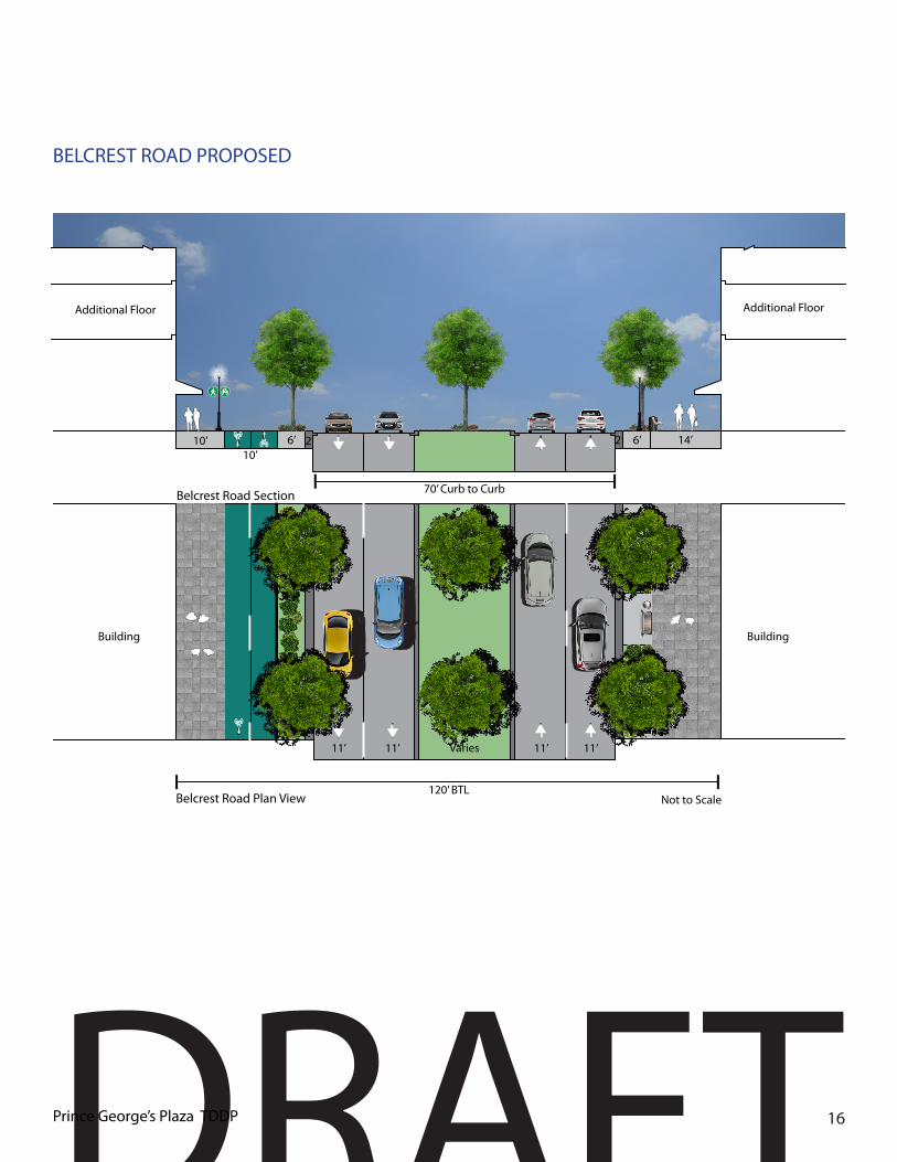
Belcrest Road
(DPW&T)
Toledo Road
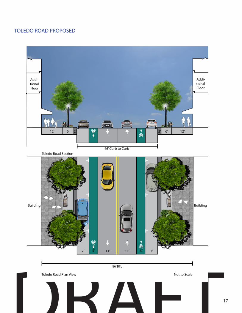
(DPW&T)
Toledo Terrace
(DPW&T)
Northwest Drive
(DPW&T)
Dean Drive (DPW&T)
Building Orientation(Entrance location)
Front Front, side Front, side Front, side Front Front
Minimum Building Setback 0’ 0’ 0’ 0’ 10’ 10’Off-Street Parking Access/Location
Rear, side Rear, side Rear, side Rear, side Rear, side Rear, side
Frontage ZonesBuffer Zone 2’ 2’ 2’ 2’ 2’ 2’Tree and Furniture Zone Urban Green Infrastructure Highly Encouraged
6’ 6’ 6’ 6’ 7’ 7’
Sidewalk Clear Zone 6’ 6’ 6’ 6’ 8’ 5’Cycle track n/a 10’ (West
Side)n/a n/a n/a n/a
Retail/ Residential Zone 6’ 6’ 6’ 6’ 10’ 10’Total Frontage Width Requirement
20’ 20’ East28’ West
20’ 20’ 27’ 24’
Traveled WaySpeed Limit (mph) 35 30 25 25 25 25Number of Through Lanes 4, 11-Foot 4, 11-Foot 2, 11-Foot 2, 12-Foot 2, 11-Foot 2, 11-FootOn-Street Parking Width n/a n/a 7’ n/a 7’ 7’Bike Lanes 5’ Off-Street 5’ 6’ Share Road Share RoadPavement Marking (Bike Buffer)
9’ n/a n/a n/a n/a n/a
Medians Varies Varies n/a n/a n/a n/aCurb to Curb 80’ 70’ 46’ 36’ 36’ 36’Total BTL to BTL 120’ 120’ 86’ 76’ 80’ 80’Access Management No Driveway
Access No Driveway Access
Vehicular access by B Streets and/or Alleys.
Vehicular access by B Streets and/or Alleys.
Vehicular access by B Streets and/or Alleys.
Vehicular access by B Streets and/or Alleys.
IntersectionsCurb Extensions Encourage (with on-street parking)
n/a n/a Yes Yes Yes Yes
Minimum Curb Return Radii (if extensions not used
SHA Standards
DPW&T Standards
DPW&T Standards
DPW&T Standards
DPW&T Standards
DPW&T Standards

DRAFTPrince George’s Plaza TDDP 14
Downtown Core and Neighborhood Edge Street Design Standards
Context
Proposed New StreetsDC
A StreetCity/Private
DC B Street
City/Private
DCPedestrian Street City/
Private
DCPromenade City/Private
ND A Street
City/Private
NDB Street
City/Private
Building Orientation(Entrance location)
Front Front, side Front, side Front, side Front Front
Minimum Building Setback 0’ 0’ 0’ 0’ 10’ 10’Off-Street Parking Access/Location
Rear, side Rear, side Rear, side Rear, side Rear, side Rear, side
Frontage ZonesBuffer Zone 2’ 2’ n/a n/a 2’ n/aTree and Furniture Zone Urban Green Infrastructure Highly Encouraged
6’ 6’ 6’ n/a 7’ 7’
Sidewalk Clear Zone 6’ 6’ 6’ n/a 8’ 5’Retail/ Residential Zone 6’ 6’ 6’ n/a 10’ 10’Total Frontage Width Requirement
20’ 15’ 18’ 40’ 27’ 24’
Traveled WaySpeed Limit (mph) 25 25 10 n/a 25 25
Number of Through Lanes 2, 11-Foot 2, 11-Foot 2, 12-Foot n/a 2, 11-Foot 2, 11-FootOn-Street Parking Width 7’ 7’ n/a n/a 7’ 7’Bike Lanes Share Road Share Road Share Road n/a Share Road Share RoadMedians n/a n/a n/a n/a n/a n/aCurb to Curb 36’ 36’ 24’ n/a 36’ 36’Total BTL to BTL 76’ 66’ 60’ 40’ 86’ 80’Access Management Vehicular access by B Streets and/or Alleys.
IntersectionsCurb Extensions (with on-street parking)
Yes Yes n/a n/a n/a n/a
Minimum Curb Return Radii (if extensions not
used
10-15 ft. 10-15 ft. 10-15 ft. 5- 10 ft. DPW&T Standards
DPW&T Standards

DRAFT15
MD 410 (EAST WEST HIGHWAY) PROPOSED
Additional Floor
Additional Floor
80’ Curb to CurbMD 410 (East West Highway) Section
6’6’12’
Not to Scale
12’5’
Bike Lane
2’2’
BuildingBuilding
MD 410 (East West Highway) Plan View
120’ BTL
11’ 11’ 11’ 11’ 9’9’ 5’5’
DRAFTPrince George’s Plaza TDDP 16
BELCREST ROAD PROPOSED
Additional FloorAdditional Floor
70’ Curb to Curb
10’
Belcrest Road Section
2’ 6’6’
Not to Scale
14’10’ 2’
BuildingBuilding
Varies
Belcrest Road Plan View120’ BTL
11’ 11’ 11’ 11’
DRAFT17
TOLEDO ROAD PROPOSED
Addi-tional Floor
Addi-tional Floor
Toledo Road Section
6’ 12’6’12’ 2’ 2’
11’11’
Toledo Road Plan View Not to Scale
7’ 7’
86’ BTL
Building Building
5’ 5’
46’ Curb to Curb

DRAFTPrince George’s Plaza TDDP 18
TOLEDO TERRACE PROPOSED
Additional Floor
Additional Floor
Toledo Terrace Section
6’ 12’6’12’
12’12’
Toledo Terrace Plan View Not to Scale
76’ BTL
Building Building
36’ Curb to Curb
2’2’
6’6’

DRAFT19
NORTHWEST DRIVE PROPOSED
36’ Curb to Curb
Northwest Drive / Dean Drive /A Street Section
8’ 7’7’ 10’10’ 8’
Not to Scale
11’11’
Northwest Drive / Dean Drive /A Street Plan View
7’7’
3’3’
Townhome
Townhome
Townhome
Townhome
86’ BTL
Single Family Home
Single Family Home

DRAFTPrince George’s Plaza TDDP 20
DEAN DRIVE PROPOSED
36’ Curb to Curb
Northwest Drive / Dean Drive /A Street Section
8’ 7’7’ 10’10’ 8’
Not to Scale
11’11’
Northwest Drive / Dean Drive /A Street Plan View
7’7’
3’3’
Townhome
Townhome
Townhome
Townhome
86’ BTL
Single Family Home
Single Family Home

DRAFT21
DOWNTOWN CORE “A” STREET
Additional Floor
Additional Floor
36’ Curb to CurbDowntown Core A Street Section
Not to Scale
6’ 12’6’12’
Building Building
Downtown Core A Street Plan View
2’2’
76’ BTL
11’ 11’ 7’7’
2’2’

DRAFTPrince George’s Plaza TDDP 22
DOWNTOWN CORE “B” STREET
36’ Curb to CurbDowntown Core B Street Section
8’8’ 5’3’3’5’
Not to Scale
Additional FloorAdditional Floor
2’ 2’
Downtown Core B Street Plan View
3’3’
BuildingBuilding
66’ BTL
11’11’ 7’7’

DRAFT23
DOWNTOWN CORE PEDESTRIAN STREET
Additional FloorAdditional Floor
Pedestrian Street Section
18’18’24’
Pedestrian Street Plan View Not to Scale60’ BTL
Building Building
24’ Curb to Curb

DRAFTPrince George’s Plaza TDDP 24
DOWNTOWN CORE PROMENADE
Additional FloorAdditional Floor
Promenade Section
15’15’ 10’
Promenade Plan View Not to Scale40’ BTL
Building Building

DRAFT25
NEIGHBORHOOD EDGE A STREET
36’ Curb to Curb
Northwest Drive / Dean Drive /A Street Section
8’ 7’7’ 10’10’ 8’
Not to Scale
11’11’
Northwest Drive / Dean Drive /A Street Plan View
7’7’
3’3’
Townhome
Townhome
Townhome
Townhome
86’ BTL
Single Family Home
Single Family Home

DRAFTPrince George’s Plaza TDDP 26
NEIGHBORHOOD EDGE B STREET
36’ Curb to Curb
Neighborhood Edge B Street Section
5’ 7’7’ 10’10’ 5’
Not to Scale
11’11’
Neighborhood Edge B Street Plan View
7’7’
3’3’
Townhome
Townhome
Townhome
Townhome
80’ BTL
Single Family Home
Single Family Home

DRAFT27
ALLEY SECTION
AdditionalFloor
AdditionalFloor
22’
Alley Section
4’ 4’
Alley Plan View
30’ BTL
22’ Curb to Curb
Building Building
Not to Scale

DRAFTPrince George’s Plaza TDDP 28
Frontage Standards and Guidelines
Intent: To create a desirable, human-scaled urban place with streets that are easy to navigate, inviting, attractive, and safe for all users. The following standards are intended to help create an attractive public realm that will entice people, businesses, and investment to the new Downtown at Prince George’s Plaza.
Design Standards
• All streets shall have sidewalks on both sides constructed to the street standards prescribed in this plan. At a minimum, all sidewalks shall have a Sidewalk Clear Zone and a Street Tree and Furnishing Zone.
• Sidewalks may have a Retail Zone on either side of the Sidewalk Clear Zone:
• One Retail Zone adjacent to the building, and, if necessary to meet seating needs
• An additional Retail Zone adjacent to, or integrated with, the Street Tree and Furnishing Zone.
• No primary building entrances or exits shall open directly into a parking lot, onto a driveway, side street, alley, loading dock, or other vehicle cartway.
• Along private streets, crosswalks shall be provided at all signalized intersections and, where warranted, selected unsignalized intersections, and shall use highly visible markings and/or decorative alternative paving material.
• Along private streets, all signalized intersections with bike lanes, cycle tracks or any type of bicycle facility as part of the road design shall include bike boxes that allow bicyclists to proceed on green ahead of motorized vehicles.
• Continuous pedestrian-scale street lighting shall be provided along all street frontages.
Design Guidelines
• On private streets, all pedestrian crosswalks should be a minimum of 12 feet wide.
• Pedestrian scrambles are permitted in private intersections (intersections of two private streets), with appropriate signalization and curb ramps.
• Additional street lighting should be provided at crosswalks to increase visibility of pedestrians.
• Along private streets, all crosswalks should be enhanced with some form of special decorative paving or artistic painting that clearly defines the area as a pedestrian crossing.
• Decorative paving or artistic painting that clearly defines an intersection of private streets is permitted.
• Parking and service access points should match sidewalk materials and patterns.
Example of a ample downtown sidewalk

DRAFT29
Street Tree and Furnishing Zone
Design Standards
• Each block shall contain at least five benches.
• Each block shall contain at least two waste receptacles and two recycling receptacles; preferably located at each corner.
Design Guidelines
• All public or privately installed street furniture, including lights, benches, waste receptacles, mailboxes, newspaper boxes and bicycle racks, or similar elements should be consistent within a project and be placed at regular intervals within the Street Tree and Furnishing Zone.
• All street furniture should be constructed of durable materials that are graffiti-, fire-, rust-, and stain -resistant.
Street Trees
Design Standards
• Street trees shall be located within the Tree and Furnishing Zone.
• Shade trees two and one-half (2-1/2) to three (3) inch caliper in size, shall be planted along each street at an average spacing of not less than twenty-five (20) feet on center nor greater than forty (40) feet on center, excluding driveway openings. Spacing allowances may be made, where necessary, to accommodate curb cuts, fire hydrants, and other infrastructure elements.
• Ornamental trees, seven (7) to nine (9) feet in height, may only be used to meet the requirements of this section where overhead wires prohibit the planting of shade trees. Ornamental trees meeting this requirement shall be planted at an average rate of one (1) tree per forty (40) linear feet, excluding driveway openings.
Example of a secluded public area with removable street furniture
Creative bike racks on sidewalk within the tree and furnishing zone
Example of outdoor sitting
Example of creative waste receptacles

DRAFTPrince George’s Plaza TDDP 30
• Street trees shall be located a minimum thirty-five (25) feet from the point of curvature of an intersection of two (2) streets.
• Street trees shall be located a minimum ten (10) feet from the point of curvature of residential driveway entrances.
• Street trees shall be located a minimum twenty (20) feet from the point of curvature of commercial driveway entrances.
• Street trees shall be located a minimum fifteen (15) feet from street light poles.
• Street trees shall be located a minimum ten (10) feet from water meters.
• Street trees shall be located a minimum ten (10) feet from storm drain inlets, hydrants, or manholes.
Design Guidelines
• Street tree species should be planted consistently within the streetscape to provide a distinct form and character to each private street.
• Plans should provide species diversity corresponding to the street character by planting different streets with different trees.
Tree interval 40 feet Center to Center/ Street Lights 40 feet Center to Center

DRAFT31
Tree Boxes
Tree boxes are openings in the sidewalks for street trees and are preferable to tree grates because of the amount of planting material they can contain.
Design Standard
• Tree grates are prohibited
Design Guidelines
• If tree boxes are provided, all boxes along the length of a single block should be of the same type for a uniform appearance. Uniform type around the entire length of a street within the Transit District, or around the entire perimeter of a plaza, square or pocket park identified in Standard XX is preferable.
• Tree boxes or pits on sidewalks 15 feet wide or greater should include additional landscaping. In addition to the tree, the tree pit may include flowering plants and shrubs. However, no plants with thorns or other sharp protrusions should be used, and these plants should be maintained below a height of 42 inches.
Landscape Screening
Design Standards
• Screening materials shall consist of evergreen trees and shrubs, walls, and fences.
• At the time of installation or planting of screening materials, screening must occupy seventy-five percent (75%) of a vertical, rectangular plane, excluding driveways, sufficiently tall and wide to accomplish the required screening.
• All loading areas consisting of loading spaces, loading docks, adjacent vehicular lanes, and service or maintenance areas shall be screened from residential areas (containing one-family detached and attached dwelling units) and all adjacent public roads.
• All dumpsters, trash pads, trash/recycling collection, or storage areas shall be carefully located and oriented on the site to be as inconspicuous as possible.
• All mechanical equipment and meters shall be screened to prevent excessive noise and visual impacts on surrounding properties.
Design Guidelines
Screening options may include:• Six (6) foot high, sight-tight fence.• Architecturally decorative walls.• Evergreen screen (height, spacing, and
variety to be determined by size and location of area to be screened).
Tree Box with an integrated urban bioswale

DRAFTPrince George’s Plaza TDDP 32
Street Lights
Design Standards
• Street lights shall either be pedestrian-scale fixtures or a combination of a roadway light and a pedestrian fixture. Pedestrian lights shall be no higher than 14 feet.
• Street lights installed along MD 410 (East West Highway) and Belcrest Road shall use PEPCO’s Teardrop or equivalent style from PEPCO’s most recent Street Light Catalog.
• All other streets in the Transit District shall use PEPCO’s Acorn or equivalent style from PEPCO’s most recent Street Light Catalog.
• Cobra fixtures and high pressure sodium fixtures shall not be permitted.
• Street light fixtures shall be spaced a maximum of 40 feet apart in the Downtown Core.
• Street light fixtures shall be spaced a maximum of 50 feet apart in the Neighborhood Edge, and may be placed in a staggered arrangement.
Design Guidelines
• Street light fixtures should allow for the hanging of banners and other amenities, including artwork, hanging flower baskets, etc.
• Street light fixtures should include electric weather protectant receptacles.
• Energy-efficient lighting should be used to conserve energy and reduce long term cost.
Lighting
Design Standards
• All pedestrian rights-of-way, including sidewalks, trails, paths, and pathways from building entrances/exits to the sidewalk, shall be continuously lit.
• Additional lighting shall be directed at crosswalks, pedestrian pathways through parking lots, and street corners, where pedestrians and vehicles interface.
• Additional lighting and/or increased illumination shall be provided at transit stops, public plazas, and parking lots.
• Consideration of security and pedestrian comfort shall be prioritized by increasing illumination low to the ground in public parking lots, at buildings entries, in public plazas, and transit stops
Design Guidelines
• Exterior areas, rear entryways, public spaces, roads, crosswalks, sidewalks, pedestrian overpasses, and trails should be well-illuminated to ensure safety and improve visibility while minimizing light spillover to other properties.
• Light fixtures should avoid conflicts with trees or other obstructions, and should direct light to specific locations and away from adjoining properties.
Highly visible crosswalk with lighting Tear drop street light Acorn street light

DRAFT33
"M
AD
ELPHI
RD
EAST WEST HWY
NICHOLSON ST
40THA
VE
TOLEDO TER
41
STA
VE
25
THA
VE
OLIVER ST
42
ND
AV
E
GUMWOOD DR
DEAN DR
ROSEMARY LN
WE
LLSP
KY
31
STA
VE
QUEENS
CHAPELRD
39
THP
L
WE
STPA
RK
DR
31ST
PL
BE
LCR
EST
RD
33RD
AVE
TOLEDO RD
FOREST HILL DR
32N
DA
VE
JAM
ESTO
WN
RD
VAN BURENST
CALVERTON DR
37THAVE
HIG
HV
IEWTER
QUEENSBURY RD
LIBERTY LN
36THAVE
MADISONST
STA
NFO
RD
ST
AM
ERIC
AB
LVD
CH
AN
SOR
YLN
COMMANDER DR
AVALON PL
LANCER PL
30
THA
VE
41
STP
L
34
THA
VE
EVER
SFIE
LDD
R
OGLETHORPE ST
AMHERST RD
TENNYSON RD
35
THA
VE
QUINTANA ST
NO
RTHW
ESTD
R
33RD
PL
CLA
YM
OR
EA
VE
OLIVER PL
ONEIDA PL
38
THP
L
DREXEL ST
FORDHAM ST
BANNING PL
WELLS
BLVD
39
THA
VE
WOODBERRY ST
WIN
DS
OR
LN
PO
NY
TRA
ILLN
BR
IDLE
PATH
LN
EDITO
RS
PAR
KD
R
BELCREST CENTER DR
TOLEDOPL
AD
ELPH
IR
D
OLIVER ST
41
STA
VE
QUEENS
CHAPELRD 4
0TH
AV
E
40
THA
VE
CALVERTON DR
25
THA
VE
41STAV
E
WELLS PKY
EAST WEST HWY
40THAVE
VAN BURENST
[Metro Green Line Station
Prince George's Plaza TDDP/TDOZPreliminary Boundary (2014)
"M 0 800Feet
T
T
T
T
T
T
Termini and Visually Interesting Features T
T
Special Corner Buildings
SC
SC
SC
SC
T
T SC
Suggested termini, visual interesting features, and special corner locations

DRAFTPrince George’s Plaza TDDP 34
Urban Design Features
Intent: To facilitate the creation of significant urban design features at signature sites that establish a distinct identity of place, create symbolic gateways and significant points of interest, and contribute to the visual and architectural character of the Transit District.
Design Guidelines
• Termini and visually interesting features are recommended at the end of critical sight lines within the Transit District. Such features can range from building articulations in the form of towers, unique architectural design of entrances and bays, as well as components of public art integrated into the design of buildings.
• Building facades should be located to terminate a vista created by the centerline of a street or open space. When building facades terminate a vista they should be designed to have a significant architectural feature located on axis with the vista.
• Special corner buildings are recommended around key intersections within the Transit District. Such buildings should visually address the corner, which can be achieved by orienting the building entrance at a diagonal facing the corner, articulating the building as a tower or a corner bay that fronts the intersection, or by setting back the building to create a small urban plaza at the ground floor. A range of strategies is encouraged around each of these key intersections to create visual interest.
Example of a prominent terminate vista juxtapositioned with others civic buildings
Example of a strong presence of civic building as a termini vista.

DRAFT35

DRAFTPrince George’s Plaza TDDP 36
Placemaking and Open Space
Intent: To create an integrated system of safe and inviting open and public spaces that encourage and facilitate active and passive uses, social interactions, and cultural events easily accessible via a short walk.
Open space designations are established by the Formula 2040 Park Typology.
Open Spaces
Design Guidelines
• Privately owned and operated open spaces should be accessible to the public whenever feasible through a public use easement.
• Open spaces should be designed in accordance with the Formula 2040 Park Typology and their associated characteristics.
• Consideration should be given to providing open spaces for important events or programming, including, but not limited to, fitness activities, passive and active uses, toddler and children urban playground, neighborhood, and community parks, dog parks, open greens, and picnic areas.
• Permeable materials are encouraged, wherever possible, to facilitate the growth of trees and vegetation, and the absorption and treatment of rainwater runoff.
Activating the pedestrian experience
Design Standards
• Sidewalk widening is permitted in the Transit District.
• Bike Corral and Bike sharing is permitted in the Transit District
• Parklet and interim public plazas are permitted in the Transit District.
Murals and Public Art
Design Guidelines
• Works of art, architectural enhancements and special landscape treatments should be located in areas where residents and visitors live, work, or congregate and should be highly visible and accessible.
• Murals or works of public art are permitted in the Transit District.
• Wherever possible, such displays should reflect the aesthetic and cultural traditions of Hyattsville, University Town Center, and Prince George’s County, including their history, present, future, and the environmental and geographic characteristics that make both the city and the county unique places.
Color
Design Guideline
• The use of bright colors for trim and accent elements are permitted and encouraged in the Transit District.

DRAFT37

DRAFTPrince George’s Plaza TDDP 38
Green Infrastructure
Design Guidelines
• Environmentally sensitive, urban-scale stormwater management facilities should be used where appropriate, including subsurface collection facilities under parking lots to store and slowly infiltrate stormwater.
• Site and street designs should avoid the use of unshielded roof, side and parking lot lights, and include the use of full cut-off optic lighting systems that provide consistent lighting levels.
• Pervious paving such as cast pressed concrete paver block, grassed cellular plastic or concrete, asphalt, concrete, stamped asphalt or concrete, pea gravel/washed stone or paving blocks, and wood or concrete paving blocks are permitted throughout the Transit District, except where expressly prohibited by another section of the County Code.
• Integrate urban-scale stormwater management measures with bioswales, naturalistic green fingers, rain gardens, waterscapes and other green/environmental site design practices that minimize stormwater run-off and increase the infiltration of rainwater into the ground
• Encourage new development to adopt LEED-ND or similar sustainability standards, incorporating innovative solutions such as green buildings, reuse of gray water, reusable energy generation onsite, technologies that lower electricity consumption, as well as green and habitable roofs where appropriate (rooftops that building occupants can use for gardening, socializing, and sunning)
Sustainable Buildings Materials
Design Guidelines
• Buildings should be built of “green” building materials. “Green” materials should meet the following criteria: produced locally or salvaged, recycled and/or recyclable; rapidly renewable; durable; containing a low embodied energy; manufactured in a less environmentally hazardous or toxic manner; for wood, certified in accordance with the Forest Stewardship Guidelines for environmentally responsible forest management; for refrigerants and fire suppression devices, not containing CFCs or Halon gas. Common “green” materials include cement/wood fiber composite siding, cellulose insulation, glue-lam beams, and concrete with fly ash content.

DRAFT39
Density and Building Height
Intent: To encourage a coordinated and attractive built environment, featuring distinct, with the incorporation of architectural design that celebrates the past, present, and future of Prince George’s Plaza and integrates existing development in a context-sensitive manner.
• These standards establish building height limits which will permit the density of development appropriate to a downtown, and a context sensitive transition to a scale compatible with surrounding neighborhoods. In keeping with best practices in transit-oriented development, the greatest height is established in the Downtown Core, along Belcrest Road and MD 410 (East West Highway).
• A story is defined as “an interior space measured from one finished floor to the next finished floor or roof above.” When a mezzanine level is present, it should be counted as an additional story.
Density• Section 27-548.06(a)(1) establishes that
“[d]evelopment within a Transit District shall not exceed the specified maximum residential density and any floor area ratio (FAR) requirements of the underlying zones. For ease of reference, the relevant density maximums are listed here:
Zone Maximum Permitted Density
R-80 4.58 dwelling units per acre
R-18 20 dwelling units per acre
R-10 48 dwelling units per acre
M-U-I (Residential/Commercial) Established by Detailed Site Plan
M-U-I (Multifamily Residential-Only) 48 dwelling units per acre
M-X-T (Base) 0.4 Floor Area Ratio
M-X-T (Optional Method of Development)
8.0 Floor Area Ratio

DRAFTPrince George’s Plaza TDDP 40
Pursuant to Section 27-548.06(b), this Transit District Development Plan establishes the height regulations for the Transit District. The height regulations for buildings consist of five features:
1. Single-story buildings2. Minimum first (ground) floor height;3. Stepback and transition requirements
(where applicable);4. Height maximums; and 5. Public amenity height/density
bonuses.
General Height/Density Standards
For the purposes of this TDOZ, building height shall be measured in number of stories above the primary or secondary ground-level public entrance located at the highest elevation. Differences in topography may permit ground-level entrances at lower elevations; these stories shall be considered basement or sub-grade floors and shall not count against the story maximum. For example, a building may front on side A at street level; an entrance on side B may be two floors below the entrance on side A. The height of the building would be measured in stories from side A.
• When a mezzanine is present, the mezzanine shall be counted as an additional story.
• Habitable space in roof/attic areas with a sloping roof shall not be counted as a story.
• Basements that are completely buried shall not count as a story.
• Raised basements shall not exceed ½ of a story in height above grade along the build-to line.
•General Height/Density Guidelines
• Corner towers, vertical bays and other features should be utilized to give the appearance of a taller building height.
Single-Story Building Height/Frontage Standards
• Single-story buildings in the Downtown Core shall have a façade of at least 20 feet in height measured from the average mean building grade at the front of the building to the top of the façade, with a minimum floor-to-ceiling height of 14 feet.
• Single-story buildings shall front on to the primary street for 100 percent of the build-to-line.
• Minimum First (Ground) Floor Height for Multistory Buildings
• Commercial, institutional, mixed-use, or multifamily residential buildings: the first (ground) floor shall be at least 20 feet high, with a floor to ceiling height of at least 14 feet.
Stepback and Transition Standards
• All buildings or portions of buildings, within 250 feet of the Oliver Street right-of-way shall be a maximum of six stories.
• All buildings or portions of buildings, within 500 feet of the Adelphi Road right-of-way shall be a maximum of six stories.
Stepback and Transition Guidelines
• All buildings should have step back of at least 10 feet above the fourth story and may have subsequent stepbacks.
• On sites or lots with multiple buildings, buildings closer to MD 410 (East West Highway) should be tallest, with building heights stepping down as they are sited closer to the adjacent community outside the Transit District.
• Buildings adjacent to the Transit District border should be the shortest buildings on a particular site or lot.
DRAFT41
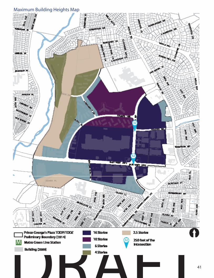
Maximum Building Heights Map

DRAFTPrince George’s Plaza TDDP 42
Maximum Building Height: 2.5 Stories
Area of coverage: • All buildings in the R-O-S, O-S, and R-80
zones
Maximum Building Height: 6 Stories
Area of coverage: • All buildings south of East-West Highway
and west of Editors Park Drive. • All buildings zoned R-10 that front on
Dean Drive or Northwest Drive. • All buildings zoned M-U-I and M-X-T west
of Northwest Drive and west of Toledo Terrace.
• All buildings that front on Toledo Terrace south of Toledo Road Extended.
• Portions of, or entire, buildings south of Belcrest Road up to 500 feet west of Adelphi Road.
• Portions of, or entire, buildings within 250 feet of the Oliver Street right-of-way.
• All buildings west of Belcrest Road south of the entrance to the Prince George’s Plaza Metro Station.Maximum Building Height: 4 Stories
Area of coverage: • All buildings in the R-18 zone
Prince George’s Plaza TDDP – Maximum Building Heights
All buildings in the Transit District are subject to the following height maximums, as measured from street level. The following table describes the areas subject to each building height maximum:
2.5 STORIES 6 STORIES
4 STORIES

DRAFT43
Maximum Building Height: 10 Stories
Area of coverage: • Except where located in the 32-story
maximum height area below: • All buildings north of Toledo Road
Extended, south of Toledo Terrace, and west of Belcrest Road, except buildings that front on Belcrest Road.
• All buildings zoned R-10 that do not front on Northwest Drive or Dean Drive.
Maximum Building Height: 16 Stories
Area of coverage: • Except where located in the 32-story
maximum height area below: • All buildings north of MD 410 (East West
Highway) east of Toledo Terrace and south of Toledo Road Extended.
• Portions of, or entire, buildings south of MD 410 (East West Highway) east of Editors Park Drive, greater than 250 feet north of Oliver Street, except the Mosaic development on Belcrest Road.
• All buildings west of, and fronting, Belcrest Road north of the Metro Sta-tion entrance and south of Toledo Road Extended.
• Portions of, or entire, buildings east of Belcrest Road greater than 500 feet west of Adelphi Road.
Maximum Building Height: 32 Stories
Area of coverage: • All buildings zoned M-X-T or M-U-I within
250 feet of the intersection of MD 410 (East West Highway) and Belcrest Road.
• All buildings zoned M-X-T or M-U-I within 250 feet of the intersection of Belcrest Road and Toledo Road.
10 STORIES 16 STORIES
32 STORIES

DRAFTPrince George’s Plaza TDDP 44
General Standards: Public Facility/Height/Density Bonus
As a new Downtown, the Transit District will attract new residents, visitors, and workers and help sustain the existing population. This will, in turn, drive demand for new, modern, easily accessible public facilities. Much of the Transit District and surrounding community is built out, and construction of new public facilities will require coordination with property owners and stakeholders, innovative approaches to design, function, and co-location of facilities, and incentives to encourage provision of public facilities within the Transit District.
One way in which this TDDP can incentivize the construction of public facilities is through the provision of height/density bonuses. These bonuses effectively permit the construction of larger buildings in exchange for the provision of land, buildings, or building space for the provision of public facilities. No height/density bonus shall be granted in the T-D-O/R-O-S, T-D-O/O-S, T-D-O/R-80, T-D-O/R-20, or T-D-O/R-18 Zones.
No height/density bonus shall be granted for the construction of buildings, or portions of buildings, within 500 feet of Adelphi Road or 250 feet of Oliver Street. However, height/density bonuses may be granted for the construction of, or conveyance of land for, amenities to be constructed in those transition areas.
For the purposes of this section, developable land is defined as the area of a parcel or property upon which development, as defined by the Zoning Ordinance, can reasonably be expected to be permitted pursuant to county, state, and federal law. Determination of developable land should take into account existing structures, rights of way, easements, regulated environmental constraints, tree cover, the Transit District standards and other considerations.
Height bonuses apply to developable land. Land dedicated or otherwise conveyed to a public agency must be developable. Land containing regulated environmental features may not be considered for conveyance to a public agency without that agency’s prior written consent. The provision of constructed buildings, structures, and/or space therein is greatly preferred over the provision of land. Buildings and parking facilities constructed pursuant to this section are subject to the Transit District Standards.
Written agreements to provide the needed land or building space shall be executed prior to, and contingent upon, an approved Detailed Site Plan, and shall be included in any DSP application package. Applicants should confer with the appropriate implementing agency to determine that agency’s space, size, amenity, and building/site feature needs in determining how best to accommodate a public facility.
Permits shall not be issued for the construction of any structure subject to a density bonus for which a public amenity agreement as described below for the provision of land and/or building space has either expired, is terminated, or otherwise becomes invalid. The execution and fulfillment of such agreements shall be a condition of approval of a Detailed Site Plan, and, pursuant to Section 27-288 of the Zoning Ordinance, “[a]ny departure from the [Detailed Site] plan shall be cause for revocation of a building permit or denial of a use and occupancy permit, unless the plan is amended in accordance with the procedure set forth in Section 27-289.” Detailed Site Plans for development subject to this section will be referred to the implementing public agency for their written comment.

DRAFT45
Should a public amenity agreement pursuant to this TDDP become invalid, terminate, or otherwise expire, the applicant may be permitted to develop at up to the original height maximum and pursuant to other conditions of the approved Detailed Site Plan. Major Amenity Bonuses
There are four major capital improvements recommended by this TDDP that qualify, due to their expense and scope, as “major amenities.” They are: 1. A regional stormwater management
facility operated by the Department of Public Works and Transportation
2. An elementary school operated by Prince George’s County Public Schools
3. A second, western entrance to the Metro Station operated by the Washington Metropolitan Area Transit Authority.
4. A regional multi-generational recreation facility operated by The Maryland-National Capital Park and Planning Commission.
The preferred building type in the Transit District is the vertical mixed use building. In the T-D-O/M-U-I zone, the maximum permitted density of these types of buildings are established by the Planning Board at the time of Detailed Site Plan approval, subject to site limitations and the height limits established by the Transit District Standards.
The major amenities are all recommended for properties in this zoning classification. Should these amenities be constructed in another underlying zone, bonuses for density are subject to the density maximums of the underlying zones, as described in Table XX above.
Major amenity bonuses are split into two categories: bonuses for the construction of major amenities, and bonuses for the conveyance of land for major amenities.
Amenity bonuses assume conveyance of the full necessary structures or land. The Planning Board may grant density bonuses for partial conveyances at the recommendation of the operating agency, provided the density bonus is less than the applicable bonus for full conveyance.
Other Amenity Bonuses
The Planning Board may grant a bonus of up to 20%, up to the maximum permitted density for the underlying zone, for the provision of other publicly-accessible amenities. This bonus encourages the construction of amenities that enrich the public realm, add destinations for workers, residents, and visitors, and enhance property values and tax revenues. Bonuses may be granted for the following:
1. Conveyance of parkland recommended by the TDDP on properties not subject to Sec. 24-124 due to exemption from a Preliminary Plan of Subdivision.
2. Construction of plazas, promenades, parks, and other public open space beyond that required by the TDDP, especially public spaces designed for performances, events, vending, or recreation;
3. Other dedicated spaces open to the public, such as museums, art galleries, cultural arts centers, community rooms, recreation areas;
4. Day care for children or senior adults and persons with disabilities;
5. Public art
6. Provision of moderately-priced dwelling units; units for rent or sale at 80% of area median income.

DRAFTPrince George’s Plaza TDDP 46
Underlying Zone Type of Development Height Area Height Bonus Maximum Density
M-U-I Vertical Mixed Use All Unlimited Established at DSP
M-U-I Institutional All Unlimited Established at DSP
M-U-I Horizontal Mixed Use All Up to 100% Established at DSP
M-U-I Commercial All Up to 90% Established at DSP
M-U-I Residential All Unlimited Up to 48 DU per acre
M-X-T All All Unlimited Up to 8.0 F.A.R
R-10 Residential All Unlimited Up to 48 DU per acre
Construction Bonuses

DRAFT47
Example of a multi purpose park amenity within an urban context
Underlying Zone Type of Development Height Limit Area
Bonus Maximum Density
M-U-I Vertical Mixed Use 32,16 Up to 75% Established at DSP
M-U-I Vertical Mixed Use All others Up to 75% or 16 Stories, whichever is less
Established at DSP
M-U-I Institutional All Unlimited Established at DSP
M-U-I Horizontal Mixed Use All others Up to 50% or 16 Stories, whichever is less
Established at DSP
M-U-I Commercial 32/16 Up to 45% Established at DSP
M-U-I Commercial All others Up to 45% or 16 Stories, whichever is less
Established at DSP
M-U-I Residential 32/16 Up to 45% Up to 48 DU per acre
M-U-I Residential All others Up to 45% or 16 Stories, whichever is less
Up to 48 DU per acre
M-X-T Vertical Mixed Use 32,16 Up to 75% Up to 8.0 F.A.R
M-X-T Vertical Mixed Use All others Up to 75% or 16 Stories, whichever is less
Up to 8.0 F.A.R
M-X-T Horizontal Mixed Use 32/16 Up to 50% Up to 48 DU per acre
M-X-T Horizontal Mixed Use All others Up to 50% or 16 Stories, whichever is less
R-10 Residential 10 Up to 75% Up to 48 DU per acre
Example of a urban plaza with removable tables-amenity
Land Bonuses

DRAFTPrince George’s Plaza TDDP 48
SIGNAGE

DRAFT49
Intent: To permit a creative and interesting array of sign designs that are different in shape, materials, and color, creating an interesting visual presentation while attracting visitors to the Transit District.
General
Design Standards
• Wayfinding and parking signs are permitted on all streets in order to facilitate direction and location and they are exempt to any allowable sign area calculations for signage.
• Attached signs shall consist of four types: band signs, board signs, window signs, or painted wall signs, as defined below. All other attached sign types require a Departure from the Transit District Standards.
• Projecting signs shall consist of two types: blade signs and vertical signs. All other vertical sign types require a Departure from the Transit District Standards.
The followings signs are not permitted in the Transit District:
• Signs which obstruct any opening intended to provide ingress or egress for any building or structure;
• Signs which obstruct the view of traffic control devices;
• Signs which, because of their shape, color, or wording, may be confused with any traffic control device (placed by a public authority), or which may mislead motorists;
• Signs which are illegal under State or Federal regulations;
.
Signage Design Guidelines
• Signage materials should be coordinated and complementary with the architectural language of the building to which they are attached.
• Signage lighting sources or elements should complement the building’s architecture.
• Materials and workmanship used for the sign should be durable, permanent, and low maintenance.

DRAFTPrince George’s Plaza TDDP 50
Attached SignsBand Signs• The Band Sign: The band sign consists of a
band of lettering across the entire width of the building.
• Band signs shall be maximum of 36” tall. • The bottom of the band sign shall not
be installed less than 10 feet above the sidewalk.
• Band signs can be painted on walls
Board Signs• Board Signs: The board sign consists of
painted or vinyl graphics on a signboard attached flush with the building wall.
Window Signs• Window Signs: The window sign is located
behind the glass or is comprised of painted, gold leaf, or vinyl applied directly to the glass.
• Window signs shall not be mounted on opaque signboards.
• The height of any window sign is limited to one third the height of the glass in the sash where the sign is installed, excluding muntins.
• The width of any window sign is limited to 90 percent of the width of the glass in the sash where the sign is installed.
• Signs may not be affixed with tape or other temporary means to the exterior nor to the interior of the glass surfaces.
• Neon signs shall be prohibited. • Decals shall not be affixed to glass.
Painted Wall Signs: • Painted wall signs shall be rectangular,
oriented horizontally or vertically, and no larger in area than 3 feet by two times the building width.
36” Max.
10’ Min.
Y’A
A BD
C
B
C
D
1/3 of Y’ max.
90 percent of X’ max.X’
X’
200 percent of X’ max.
3 feet max.
Diagram of Band Sign Dimension
Diagram of Board Sign Dimension
Diagram of Window Sign Dimension
Diagram of Painted Wall Sign Dimension

DRAFT51
Band Sign Precedent
Board Sign Precedent
Window Sign Precedent
Painted Wall Sign Precedent
Blade Sign Precedent

DRAFTPrince George’s Plaza TDDP 52
Vertical Sign Precedent
Projecting Signs
Blade Signs: • The top of the blade sign shall be between
9 feet and 12 feet above the sidewalk. • The blade sign shall be 32 inches tall
maximum. • Blade signs shall be no more than 4 feet
wide nor project more than 5 feet from the wall.
• No blade sign shall exceed 6 square feet • Brackets or other suspension device
shall match the architectural style of the building and shall not be computed as part of the allowable size of the sign.
Vertical Signs: • Vertical corner signs are permitted at the
corners of blocks. • Vertical corner signs shall be mounted a
minimum of 12 feet in height from the sidewalk, measured to the bottom of the sign.
• The height of the sign shall not exceed the first-story wall height.
• Vertical corner signs shall be mounted 12 inches maximum away from the exterior wall of the building and shall be a maximum of 3 feet wide.
• They may project perpendicular from one side of the building or at a 45 degree angle to the corner.
Diagram of Blade Sign Dimension
Diagram of Vertical Sign Dimension
Y’ max.
12’ min.Y’
3 feet max.
12” max.A
A
9 to 12 feet
BA
32” max.A
5 feet max.A

DRAFT53
Ground Signs: Sculptural and A-frame sign boards placed on the sidewalk are permitted if they are temporary and removed during non-operating hours.
Awning Signs: Signage may be painted either on the fringe of an awning or in the center of the body of the awning. • Awning signs shall be painted directly on
the canvas. • Back lit awnings are prohibited. • Signs that occupy the fringe of the awning
may fill the entire height and width of the fringe up to a maximum fringe height of 9 inches.
High Rise Building Identification Signs
Design Standards:• The maximum area for high rise building
identification signs is five square feet for every 1,000 square feet of gross floor area of the principal building, provided, however, that in no event may the total sign area for high rise building identification signs exceed 800 square feet per building.
• Such signs shall be placed upon the wall or parapet near the top of the principal building and not on any parking garage or other subordinate structure.
• Such signs may not extend above the roof line of any building except when placed upon a parapet, in which case the sign may not extend above the parapet wall.
Design Guidelines• Up to two high rise building identification
signs are permitted per building. If two such signs are installed, they should be placed on two separate sides of the structure building.
• If illuminated at night, the text within a high rise building identification sign should be lit with white, though a single logo element of the sign may be lit with colored light
Home-based Business Signs
• Signs advertising a legally-existing home-based business shall be permitted.
• Home-based Business Signs shall be a maximum size of 6 square feet.
• Home-based Business Signs may be mounted to a freestanding post, hung below a porch roof, or mounted to a building wall.
• One sign advertising a home-based business is permitted at each frontage.
• Security Signs: One sign providing notice of a security system is permitted at each frontage.
• Real Estate “For Sale” and “For Rent” Signs: One real estate sign advertising a property for sale or rent may be displayed at each frontage.
• Signs may not encroach into an adjacent private property.
Freestanding Signs
• Freestanding signs shall be located only in the Street Tree and Furnishing Zone or Retail Zone within the Downtown Core.
• Freestanding signs shall not exceed eight (8) feet in height.
• Freestanding signs shall not exceed three (3) feet in width.
Ground Sign Precedent

DRAFTPrince George’s Plaza TDDP 54
Gobo
Gobo (“goes between optics”) projection signs are signs displayed on a fixed surface by projecting light through a semitransparent template. Each principal building in the Down-town Core may display one static gobo sign. Additionally, each ground floor retail use may project one static gobo sign onto the adjacent sidewalk. All gobo signs are subject to the fol-lowing regulations:
Design Standards
• Gobos may only project from dusk to 2:00 a.m. the following day.
• Gobos may not project upon parts of buildings that are used for residential or lodging purposes.
• Because gobos are temporary in nature, they do not count toward the calculation of maximum allowable sign area.
Example of a GOBO sign projected to building
Interactive Storefronts
Interactive storefronts are digital signs oriented and designed to interact with pedestrians passing along the adjacent sidewalk. Interactive storefronts are permitted only within the Downtown Core. All interactive storefronts are subject to the following regulations:
Design Standards
• Interactive storefronts shall not count towards the calculation of maximum allowable sign area.
• Interactive storefronts may display onsite and offsite messages.
• Messages displayed on interactive storefronts shall not be oriented towards passing motorists. Example of an interactive storefront sign
• Interactive storefronts are only permitted along retail zones that are at least 15 feet wide, measured perpendicular to the storefront, or along publicly-accessible plazas that are at least 15 feet wide, measured perpendicular to the storefront.
• Interactive storefronts may comprise no more than 25 percent of the width of the applicable building face.
• Buildings with interactive storefronts are not exempt from minimum window transparency requirements.
Digital Onsite signsDigital onsite signs are onsite signs that display images or messages through a digital medium. Digital onsite signs are permitted within the Downtown Core, subject to the following regulation:
• Digital onsite signs are only permitted for nonresidential uses.

DRAFT55
Digital Screens
Digital screens are signs comprised of a television-like screen that displays full-motion images and messages through the digital manipulation of light. Digital screens are permitted in Downtown Core, subject to the following regulations:
• Digital screens must be flush with the building façade, architecturally integrated into the building onto which it is affixed, and oriented towards the pedestrian and not passing motorists.
• Digital screens shall be oriented to publicly-accessible open space of at least 0.1 acres in area.
• Digital screens may not exceed 400 square feet per principal building or 1,600 square feet per principal building if built and maintained behind glass windows designed for such purpose.
• Digital screens are prohibited above 60 feet from the ground, or the top of the building’s second floor, whichever is less, and may not be below 12 feet above the surface of the nearby sidewalk, plaza, or other walkway.
Example of a digital screen
Monument Signs
Monument signs are permitted, subject to the following regulations:
• Monument signs are only permitted on sites with at least 150,000 square feet of building area and a public or private plaza at least 0.1 acres in area
• Only one monument sign is permitted per building.
• Monument signs must be located in either the Street Tree and Furnishing Zone, the Retail Zone, or the Residential Zone and shall not be located within five feet of any public right-of-way.
• Monument signs should not exceed 30 feet in height, and shall not exceed 300 feet square in area and shall not be obstructed by landscaping.
• Monument signs may only display onsite directory and identification material.
• A monument sign may contain an electronic directory screen of up to 50 inches diagonal, provided that it is not visible to motorists on nearby roads.
Example of a monument sign

DRAFTPrince George’s Plaza TDDP 56
Single-Family Detached Home and Townhome Development Identification
• Maximum Sign Area per sign face shall be 24 square feet, not exceeding four feet in height.
• Maximum sign height shall be four feet above established lot grade
• Entranceway signs shall be separated from signs at other entranceways by at least 200 feet and from other on-site signs by at least 100 feet, such distance to be measured along the property line.
• Sign lighting sources or elements should complement the building’s architecture and illuminate the sign only.
• Signs should be located within 30 feet of an entranceway as follows: Wall-mounted, one-face on each side of the entranceway, mounted flat against the entranceway wall. Ground-mounted, one-face or two-face back-to-back or “V” with maximum 45 degree angle.
Example of a development identification

DRAFT57
Parking and Transportation Adequacy
Intent: The Transit District standards for parking are intended to promote a “park once” environment that enables people to conveniently park and access a variety of uses in a pedestrian-friendly environment where streetscapes are vibrant and active and not dominated by parking lots or garages. The required off-street parking spaces within the Transit District are designed to minimize large parking areas while allowing for a phased reduction in parking ratios as the Transit District begins to develop in accordance with the vision and recommendations of the TDDP. Parking minimums are eliminated, and a surface parking cap is included to encourage construction of structured parking as well as the use of transit and transportation demand management strategies.
• There is no minimum number or ratio of off-street parking spaces for any develop-ment within the Transit District.
• In the Neighborhood Edge, off-street park-ing is not permitted for non-residential uses, except for public facilities owned and operated by a government agency.
• The maximum number of off-street park-ing spaces permitted for non-residential and residential development is specified in Table XX below. For the purposes of this table, the type of development refers to its description in the Table of Uses.
Character Area
Residential Development
Commercial/Industrial Development
Downtown Core
1.25 spaces per dwelling unit
2.5 spaces per 1,000 square feet of gross leasable area
Neighbor-hood Edge
1.5 spaces per dwelling unit
N/A
Design Standards
• The maximum number of off-street park-ing spaces permitted for each non-residen-tial, non-commercial, non-industrial land use type that is otherwise not specified or covered by Table XX shall be equal to 80 percent of the minimum number of required off-street parking spaces in accor-dance with Section 27-568(a) of the Zoning Ordinance.
• At no point shall the total number of surface parking spaces within the Transit District exceed 10,500.
• All applicants shall demonstrate how their proposed development reduces the total number of surface parking spaces within the Transit District.

DRAFTPrince George’s Plaza TDDP 58
• All parking spaces that are provided must be unbundled from the leasing and/or rental rates of associated development.
• All new structured parking facilities shall include secure bicycle parking. One bicycle parking space shall be provided for every 10,000 square feet of building area for office, retail, hospitality, and other com-mercial and public/institutional uses. One bicycle parking space shall be required for every 20 units for multifamily residen-tial development. These bicycle parking requirements are cumulative for mixed-use development, and both open and covered bicycle parking areas should be provided, as appropriate.
Transportation Adequacy Standard
• Within the Prince George’s Plaza Transit District, the transportation facilities adequacy standard shall be Level-of-Service E for individual critical intersec-tions calculated in accordance with procedures outlined in the guidelines maintained by the Prince George’s County Planning Department.
• The selection of critical intersections for any development or redevelop-ment project within the Transit District shall be limited to any of the existing or planned intersections along Belcrest Road and Toledo Terrace.
•
• Parking may be located on- or off-site within one-quarter mile walk of the devel-opment site. When offsite parking is used to meet any parking needs, the applicant shall provide a site plan and narrative state-ment demonstrating that parking is pro-vided off-site, and that pedestrian facilities necessary to serve the walk from parking facility to building will be constructed prior to opening of the parking facility.
• Carpool and vanpool parking spaces shall be required at a minimum ratio of one reserved high occupancy vehicle space per every 100 regular parking spaces for any development including in excess of 50,000 square feet of office use. Free or reduced parking costs for authorized carpools and vanpools are encouraged.
Design Guideline
• Commercial parking facilities should leave at least 25 percent of their spaces avail-able for hourly/daily rental by the general public.

DRAFT59
Surface Parking Facilities
Design Standards
• Off-street surface parking is prohibited except where at least one of the following conditions apply:
• The surface parking was legally existing on the date of approval of this TDDP
• The surface parking is permitted subject to a valid Detailed Site Plan approved prior to the date of approval of this TDDP.
• The surface parking will be located on land that was in legal use as a surface off-street parking lot or a building on the date of approval of this TDDP.
• The surface parking lot will be constructed by a public or quasi-public agency to provide access to a public facility.
• The Planning Board may permit construction of a new surface parking lot where the applicant will remove an equivalent square footage of existing impervious surface and create an equivalent or greater square footage of green, unpaved, space.
• To the extent that surface parking is permitted within the Downtown Core, it shall be provided through alteration or reconstruction of surface parking lots existing or approved by the Planning Board on the date of approval of this TDDP.
• Surface parking lots not legally existing on the date of approval of this TDOZMA shall not front nor have entrances from or exits onto existing or proposed “A” streets. New surface parking lots may enter from or exit
into existing surface parking lots, such as at The Mall at Prince Georges.
• Alleys and mid-block parking areas shall be hidden or screened from street frontage view by the back or side of buildings that front on public streets.
• A minimum of one pedestrian walkway shall be provided for every four head to head parking rows
• All new surface parking lots shall be screened from streets by buildings, landscaping, or any other cover that mitigates the view of the parking lot from public view.
• On “B” Streets, alleys, or service streets, one to two surface parking entrances shall be permitted per block, however; entrances shall be separated by 100 linear feet
• Parking entrances shall be located on “B” Streets, alleys, or service roads.
• Tandem Parking and Hydraulic Lifts shall be permitted in unattended parking facilities used for residential purposes when both spaces are utilized by a single dwelling.
• Tandem Parking and Hydraulic Lifts shall be permitted in any attended parking facility.
• At least one (1) shade tree shall be provided for each three hundred (300) square feet (or fraction) of interior landscape area provided. These trees shall have a clear trunk at least six (6) feet above finished grade level.
• Planting spaces must be large enough to allow for healthy tree growth and must be protected from car overhangs and opening car doors

DRAFTPrince George’s Plaza TDDP 60

DRAFT61
• A minimum of one hundred sixty (160) square feet of contiguous pervious land area shall be provided for each tree. No tree planting area shall be less than six (6) feet wide in any dimension.
• A curb or wheel stop shall be provided for all parking spaces abutting planting or pedestrian areas to protect those areas from overhanging by parked vehicles.
• Planting islands that are parallel to parking spaces on both sides shall be a minimum of nine (9) feet wide to allow car doors to swing open
• In cases where a planting island is perpendicular to parking spaces and the spaces head into the planting island on both sides, the island shall be a minimum of nine (9) feet wide to allow for bumper overhang. If parking spaces are located on only one side of such a planting island, the island shall be a minimum of six (6) feet wide.
• Existing shade trees (except an invasive species) may be retained and credited toward fulfilling parking lot interior planting requirements if appropriate measures are taken to provide long-term viability based on the species, condition, and size of the tree; the limits of disturbance, allowing a minimum area of seventy percent (70%) critical root zone retention protection during construction; and specialized tree management practices, as approved by the planning director (or designee).
• Main drive aisles shall be separated from abutting parking spaces by a minimum six (6) foot wide interior planting area.
• A minimum of one (1) interior planting island shall be provided on average for every ten (10) contiguous spaces
• Surface Parking lots shall be landscaped with a minimum of one tree per 24 spaces and a minimum of one Landscape Island for every 12 spaces.
• Every other row of parking shall include a landscaped median for the entire length of a parking bay.
• The median shall be planted with large shade trees approximately every 40 feet.
• Where a tree planting island occurs the entire length of a bay, there shall be a minimum of one planting island every 20 spaces and a large tree in each island.
• Pervious surfaces shall be permitted. Pervious concrete, pervious pavers, and pervious asphalt
• The following requirements shall only apply to surface parking lots more than fifty thousand (50,000) square feet in area:
• Option 1- There shall be no more than two (2) contiguous parking bays without the provision of a minimum nine (9) foot wide island separating the two bays from additional parking bays or drive aisles; or
• Option 2- At least one (1) shade tree shall be provided for each two hundred (200) square feet (or fraction) of interior landscape area provided. These trees shall have a clear trunk at least six (6) feet above finished grade level.

DRAFTPrince George’s Plaza TDDP 62
• Design Guidelines
• New surface parking lots should be permitted on B streets.
• Planting islands should be used to define
circulation patterns, break up rows of parking, and to soften the visual impact of large expanses of pavement.
• In general, impervious areas within parking lots should be evenly distributed throughout the parking lot to maximize shading.
• Islands should be provided at both ends of parking rows to protect parked cars from moving vehicles and to ensure more even distribution of shade throughout the parking lot.
• Inlands should incorporate into their design urban green design infrastructure methodologies to capture water runoff in order to allow water percolation into the soil.
• Parking facilities should incorporate pervious material and other green infrastructure design methodologies that will diminish storm water runoff.
• Parking facilities should provide areas for car sharing vehicles, electric chargers, bicycle parking or any new sustainable methodology may be introduced into the market in the future.
• Trees in or at the edge of parking lots should be major shade trees that can be trimmed so that at maturity cars and trucks may circulate beneath the canopy without causing damage.
• Good visibility in the parking lot is important, both for neighborhood security
Minimum width of landscape island parallel to spaces (parking on both sides)
Minimum width of landscape island perpendicular to spaces (parking on both sides)
Minimum width of landscape perpendicular to spaces (parking on one side)
Parking bay separation

DRAFT63
and traffic safety. The use of landscaping elements and plants that restrict visibility, such as tall shrubs, evergreen trees, and low-branching trees, should be avoided.
• The use and location of plant materials at vehicular entrances should be placed to maintain safe sight distances.
• Plants in parking lots are subject to many adverse conditions and are not likely to receive consistent care. Accordingly, principles of sustainability should be considered when selecting plant materials. Specifically, plant material should be moderate-to-slow growing, require little maintenance, and tolerate such conditions as sun, wind, drought, glare, reflected heat, salt and chemicals, and restricted planting spaces.
Above-Grade Parking Structures
Design Standards
• A structured parking garage shall not front onto MD 410 (East West Highway) or Belcrest Road at ground level. On-site, off-street parking for buildings located along MD 410 (East West Highway) or Belcrest Road shall be located behind, below, or above those buildings.
• Entrances to and exits from above-grade parking structures shall not be located on A Streets.
• Where otherwise permitted, parking garages that front directly on a street shall be provided with architectural treatment, liner uses/buildings, murals, landscape or any other screening techniques in order to screen the garage from public view.
• Internal elements such as pipes, fans, lighting shall be concealed from public view. Where possible, ramping should be internalized.
Design Guidelines
• Parking structures should be designed as an integral component of the coordinated site plan and architectural theme.
• Garages should use articulation or fenestration treatments that break up the massing of the garage and/or add visual interest.

DRAFTPrince George’s Plaza TDDP 64
Underground Parking
Design Standards
• A maximum of two garage entrances shall be permitted on B Streets, alleys, or service roads.
Loading
Design Standards
• All buildings in the M-U-I, R-10, and R-18 zones shall have a minimum of one loading space per building.
• All buildings in the M-X-T zone shall have a minimum of one loading space per building, except for townhomes or other single-family attached dwelling units.
Example of retail/restaurant integrated in parking garage
Example of an iconic multi-level parking garage
Example of an iconic garage lighted up with colors.
Example of a parking sign

DRAFT65
Walls, Fences, and Gates
Design Standards
• Wall, fences, and gates are prohibited in the Downtown Core, except for the following:
• Except where expressly permitted by this TDDP for screening purposes; or
• As required for retention wall. • Fences and gates, up to a height
of 40 inches, are permitted to delineate outdoor seating areas within the Retail Zone for eating and drinking establishments.
• Above grade walls are prohibited along streets in the Transit District, except for the following:
• Except where expressly permitted by this TDDP for screening purposes; or
• As required for retention of earth.
• Fences enclosing all or a portion of a rear or side yard and garden walls are permitted only in the R-20 and R-80 zones and shall not occur forward of the rear of a primary building.
• Chain link fencing, barbed wire, wire mesh, corrugated metal or fiberglass, split fencing, sheet metal, and paneled materials shall not be permitted.
Design Guidelines
Fence type should be consistent along a block face.
Example of an outdoor dining sitting separation within the public realm
Clear example of frontage zones with outside restaurant sitting

DRAFTPrince George’s Plaza TDDP 66
“Observe always that everything is the result of change, and get used to thinking that there is nothing Nature loves so well as to change existing forms and make new ones of them.
- Marcus Aurelius, emperor of Rome (121-180 AD))

DRAFT67
DOWNTOWNCORE
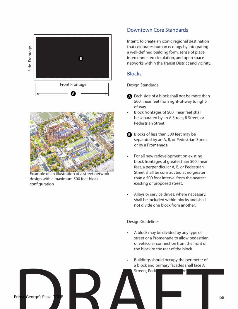
DRAFTPrince George’s Plaza TDDP 68
Downtown Core Standards
Intent: To create an iconic regional destination that celebrates human ecology by integrating a well-defined building form, sense of place, interconnected circulation, and open space networks within the Transit District and vicinity.
Blocks
Design Standards
• Each side of a block shall not be more than 500 linear feet from right-of-way to right-of-way.
• Block frontages of 500 linear feet shall be separated by an A Street, B Street, or Pedestrian Street.
• Blocks of less than 500 feet may be separated by an A, B, or Pedestrian Street or by a Promenade.
• For all new redevelopment on existing block frontages of greater than 500 linear feet, a perpendicular A, B, or Pedestrian Street shall be constructed at no greater than a 500 foot interval from the nearest existing or proposed street.
• Alleys or service drives, where necessary, shall be included within blocks and shall not divide one block from another.
Design Guidelines
• A block may be divided by any type of street or a Promenade to allow pedestrian or vehicular connection from the front of the block to the rear of the block.
• Buildings should occupy the perimeter of a block and primary facades shall face A Streets, Pedestrian Streets, or Promenade.
Example of an illustration of a street network design with a maximum 500 feet block configuration
Front Frontage
Side
Fro
ntag
e
A
B
A
B

DRAFT69
Downtown Core A Street
Design Standards
• The following streets existing in the Downtown Core on the date of approval of this TDDP/TDOZMA are to be considered “A” Streets:
• MD 410 (East West Highway)• Belcrest Road• Toledo Terrace• America Boulevard• Toledo Road• Editors Park Drive• Southernmost east-west street in
University Town Center
• Primary building entrances shall be located on A streets,
• No service area or loading dock shall be permitted adjacent to any roadway unless enclosed such that all sides appear as a primary facade similar to the primary façade of the principal building, including design, detail, finished material, and landscaping.
Downtown Core B Street
Design Standards
Streets existing in the Downtown Core on the date of approval of this TDDP/TDOZMA not identified as “A” Streets are to be considered “B” Streets.
• Delivery services, loading decks, dumpsters, parking facility (surface and structured) entrances, and utilities servicing buildings fronting on A Streets or pedestrian streets shall be located on B streets.
Design Guidelines• Secondary building entrances should be
located on these streets.
Downtown Core Pedestrian Streets / Promenade
Design Standards
• Access to a Promenade shall be limited to bicycles and pedestrians. Vehicular access is prohibited on promenades, except emergency and service vehicles, and other temporary access as permitted by the Director of Public Works and Transportation.
• Service and loading entrances are not permitted on Pedestrian streets or promenades.
Example of A street with mixed-use development framing the street

DRAFTPrince George’s Plaza TDDP 70
Frontage Element Minimum Width DepthTotal Frontage 15 ft. Retail Zone 4 ft. Sidewalk Clear Zone 4 ft.Street Tree & Furnishing Zone 5 ft.Door Swing Zone 2 ft.Miscellaneous3. Street trees shall be spaced 40 ft. maximum apart on center to center4. Streetlights shall be placed 40 ft. maximum apart on center to center
Frontage Element Minimum Width DepthTotal Frontage 20 ft. Retail Zone 6 ft. Sidewalk Clear Zone 6 ft. Street Tree & Furnishing Zone 6 ft.Door Swing Zone 2 ft.Miscellaneous 1. Street trees shall be spaced 40 ft. maximum apart on center to center2. Streetlights shall be placed 40 ft. maximum apart on center to center
Downtown Core A Street Downtown Core B Street
A
BC
D E A
B C D E
A AB BC CD DE E

DRAFT71
Frontage Element Minimum Width DepthTotal Frontage 18 ft. Sidewalk Clear Zone 12 ft.Tree & Furniture Zone 6 ft.Miscellaneous1. Street trees shall be spaced 40 ft. maximum apart on center to center2. Streetlights shall be placed 40 ft. maximum apart on center to center
Pedestrian Street andPromenade
A
BC
ABC
Example of a Promenade with a courtyard
Example of a Pedestrian street

DRAFTPrince George’s Plaza TDDP 72
Building Placement Build-to Line (Distance from Lot Line)Front Regulated by
Roadway SectionSide Street Regulated by
Roadway SectionBTL Defined by a Building
Front 100% min. A Street, Pedestrian Street,
or Promenade.80% min. B Streets
or PromenadeSide Street 100% min. A Street,
Pedestrian Street, or Promenade.
80% min. B Streets or Promenade
Min. Setback ( Distance from Lot Line)Side 0’Rear 0’
Zone M-U-I / M-X-TAdjacent to Any
other zone0’
Miscellaneous1. BTL shall be defined by building within 10-foot of the corner along the front2. A building form with a chamfered corner is allowed only on corner lots and only if a corner entry is provided.3. Entire BTL/ROW must be defined by a buildings on A Streets, Pedestrian Street, or Promenade.
Downtown Core - One StoryRetail - Office - Institution
Building FormHeightMain Building Regulated by Zone and
Building HeightsBuilding Facade Height
20’ min.
Ground Floor Ceiling
14’ min. clearance
Miscellaneous5. Primary entrance shall be located along the front facade.6. Loading docks, overhead doors, and other service entries shall not be located on A streets, Special Pedestrian Streets, or Pedestrian Bicycle Promenade7. Any buildings wider than 50’ shall be designed to read as a series of building fronts no wider than 50’ each.8. All Utility placement shall be located in Alleys or the rear of the buildings.
A
B
CD
E
Primary Frontage
Seco
ndar
y F
ront
age
A
BC
DE
FG
4. No planting strips allowed between sidewalk and building unless specified on roadway sections.
Property Line
Setback Line
Buildable Area
Back of Curb
Legend:
Example of an one story retail building
G
G
F

DRAFT73
Building Placement Build-to Line (Distance from Lot Line)Front Regulated by
Roadway SectionSide Street Regulated by
Roadway SectionBTL Defined by a Building
Front 80% min. A Street, Pedestrian Street, or
Promenade. 60% min. B Streets
or PromenadeSide Street 80% min. A Street,
Pedestrian Street, or Promenade.
60% min. B Streets or Promenade
Min. Setback ( Distance from Lot Line)Side 0’Rear 0’
Zone M-U-I / M-X-TAdjacent to Any
other zone0’
Miscellaneous1. A building form with a chamfered corner is allowed only on corner lots and only if a corner entry is provided.2. No planting strips allowed between sidewalk and building unless specified on proposed roadway sections.
Downtown Core MultistoryRetail - Office - Apartment - Institution
Building FormHeightMain Building Regulated by Zone
and Building HeightsAncillary Building
Two Stories max.
Ground Floor Ceiling
14’ min. clearance
Upper Floor(s) Ceiling
8’ min. clearance
Building set-back
10’ max after four stories.
Miscellaneous3. All floors shall have a primary entrance along the front facade.4. Any buildings wider than 50’ shall be designed to been seen as a series of building fronts no wider than 50’ each.5. Loading docks, overhead doors, and other service entries shall not be located on A streets, Pedestrian Streets, or Promenade.6. All Utility placement shall be located in Alleys or the rear of the buildings.
Front Frontage
Side
Fro
ntag
e
A
BC
D
E
A
B
CD
F
F
G
H
G
H
E
Property Line
Setback Line
Buildable Area
Back of Curb
Legend:
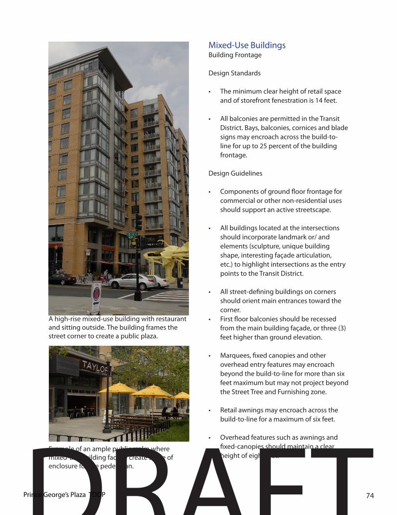
DRAFTPrince George’s Plaza TDDP 74
Mixed-Use BuildingsBuilding Frontage
Design Standards
• The minimum clear height of retail space and of storefront fenestration is 14 feet.
• All balconies are permitted in the Transit District. Bays, balconies, cornices and blade signs may encroach across the build-to-line for up to 25 percent of the building frontage.
Design Guidelines
• Components of ground floor frontage for commercial or other non-residential uses should support an active streetscape.
• All buildings located at the intersections should incorporate landmark or/ and elements (sculpture, unique building shape, interesting façade articulation, etc.) to highlight intersections as the entry points to the Transit District.
• All street-defining buildings on corners should orient main entrances toward the corner.
• First floor balconies should be recessed from the main building façade, or three (3) feet higher than ground elevation.
• Marquees, fixed canopies and other overhead entry features may encroach beyond the build-to-line for more than six feet maximum but may not project beyond the Street Tree and Furnishing zone.
• Retail awnings may encroach across the build-to-line for a maximum of six feet.
• Overhead features such as awnings and fixed-canopies should maintain a clear height of eight feet.
Example of an ample public realm where mixed-use building facade create sense of enclosure for the pedestrian.
A high-rise mixed-use building with restaurant and sitting outside. The building frames the street corner to create a public plaza.

DRAFT75
• Fenestration should be a minimum of 70 percent of first floor facades along A streets. On B streets where retail is the first floor use, the minimum percentage is 60 percent of the ground floor facade.
• Retail entries should be spaced along a frontage at 75-foot intervals maximum to encourage active streetscape. Tighter spacing is encouraged.
• The awning frame should project from the building at least six feet in order to provide shade and shelter for pedestrians.
• The awning frame should be a minimum of eight feet above the sidewalk.
• The awning, canopy, or umbrellas of unenclosed restaurants should be adequately secured, retractable, or removable.
• Awnings should create a visual “break” between storefronts.
• Awnings should be attached above the display windows and below the cornice or sign panel. Individual awnings should be installed over each separate opening.
• Metal, plasticized, synthetic and back-lit awnings should not be permitted.
Color
Design Guidelines
• The use of bright colors for trim and accent elements is encouraged to help highlight architectural details on the facade.
• The color scheme should be compatible with the retail or restaurant style.
Fenestration
Design Standards
• Tinted or mirrored glass, or glass blocks are not permitted.
• Facades at the ground level facing A Streets, Pedestrian, Promenade, or fronting an open space shall be visually permeable (clear glass windows, doors, etc.)
• At a minimum, 50% of the ground-floor façade shall consist of transparent materials (glass).
Awnings
Design Guidelines
• Awnings should be designed to be in proportion with other building elements and the overall width of the sidewalk adjacent to the building.
• Awnings should not cover the expression line (a horizontal linear element extending across a facade evidenced as a noticeable difference of projection or recess, change of color or material, or identified as a clear architectural feature of ornamentation such as a cornice) area of the facade, but work with the structural bays or opening arrangement of the building.
Example of an ample public realm where mixed-use building facade creates sense of enclosure and safety

DRAFTPrince George’s Plaza TDDP 76
Articulation
Design Guidelines
• Architectural treatment is recommended at the expression line, to provide a shadow line, pattern or texture effect. The treatment may be molding, projection, material change or other architectural element that serves to separate the lower story from the upper stories of the building facade at that location.
• Roof lines, parapets and building heights should be architecturally articulated, diverse in design form and varied in height with adequately scaled and proportioned architectural cornices and applied treatments which complement the building’s design.
• The architecture should incorporate some of the following; colonnades, gables, hip roofs, towers, dormers, archways, and covered entries, repetitive window openings, arched and corbelled parapets, cornices, transoms or similar features.
• Upper story wall treatment should be coordinated and complement the design of the lower story facade
• Along primary building facades facing streets, façade articulation should average a minimum of 50 feet.
• Blank walls should be avoided because they disrupt the street pattern and make an uninviting pedestrian experience; however, if necessary, blank walls should not be more than 10 to 20 feet wide.
• Building corners should be articulated.

DRAFT77
Multifamily Residential BuildingsBuilding Frontage
Design Guidelines
• All residential lobby entrances should front onto streets. Ground floor residential units with individual entrances onto the street are encouraged.
• Minimum clear dimension in the ground floor of residential buildings shall be at least nine (9) feet.
• Lobby entrances should be at grade.
• Bays, balconies, cornices, stoops and shading devices may encroach across the build-to-line for a maximum of 6 feet.
• All handicapped ramps should be internal to the building.
• Sign lighting sources or elements should complement the building’s architecture and illuminate the sign only.
Example of a multifamily residential building
Example of architectural articulation

DRAFTPrince George’s Plaza TDDP 78
Architectural Standards
Building Entrances
Design Standards
• Primary entrances shall be located at the front facade of the buildings. If a building fronts on both A and B streets, Pedestrian Street, or Promenade, its primary entry shall be located on the A street.
• Service entrances and loading areas shall be at the rear of the building away from public views.
• Buildings constructed adjacent to the existing pedestrian bridge over MD 410 (East West Highway) shall provide at-grade access to the existing bridge through incorporation of the bridge into the building design or construction of a connecting bridge. This connection shall not be provided through any type of grading.
Design Guidelines
• Door style, materials and colors should relate back to the overall storefront design (color scheme, style, and focal point.)
• Recessed entries are recommended in the Transit District.
• Primary entrances should be designed with architectural articulation.
• Secondary entrances should be located at the rear or sides of buildings.
• In order to provide for façade articulation, building facades may step back a maximum of two feet from the build-to-line for a maximum of 30 percent of the building face along a block face.
• Porches and stoops may encroach beyond the build-to-line within the private frontage for a maximum of 10 feet.
• Individual buildings may be recessed from the build-to-line when required to save an existing tree.
Articulation
Design Guidelines
• Architectural treatment is recommended at the expression line, to provide a shadow line, pattern or texture effect. The treatment may be molding, projection, material change or other architectural element that serves to separate the lower story from the upper stories of the building facade at that location.
• Roof lines, parapets and building heights should be architecturally articulated, diverse in design form and varied in height with adequately scaled and proportioned architectural cornices and applied treatments which complement the building’s design.
• The architecture should incorporate some of the following; colonnades, gables, hip roofs, towers, dormers, archways, and covered entries, repetitive window openings, arched and corbelled parapets, cornices, transoms or similar features.
• Upper story wall treatment should be coordinated and complement the design of the lower story facade
• Along primary building facades facing streets, façade articulation should average a minimum of 50 feet.
• Blank walls should be avoided because they disrupt the street pattern and make an uninviting pedestrian experience; however, if necessary, blank walls should not be more than 10 to 20 feet wide.
• Building corners should be articulated.

DRAFT79
Multifamily Residential Buildings
Building Frontage
Design Guidelines
• All residential lobby entrances should front onto streets. Ground floor residential units with individual entrances onto the street are encouraged.
• Minimum clear dimension in the ground floor of residential buildings shall be at least nine (9) feet.
• Lobby entrances should be at grade.
• Bays, balconies, cornices, stoops and shading devices may encroach across the build-to-line for a maximum of 6 feet.
• All handicapped ramps should be internal to the building.
• Sign lighting sources or elements should complement the building’s architecture and illuminate the sign only.
Example of a multifamily residential main building entrance facing a A street
Corner building intersection with more than 20 feet highly articulated facade with main entrance at the corner
Mixed-use buildings with restaurants and a grocery store addressing the street with an ample public realm

DRAFTPrince George’s Plaza TDDP 80
Neighborhood Edge

DRAFT81
Neighborhood Edge Standards
Intent: To create an iconic regional destination that celebrates human ecology by integrating a well-defined building form, sense of place, interconnected circulation, and open space networks within the Transit District and vicinity.
Blocks
Design Standards
• Each side of a block shall not be more than 500 linear feet from right-of-way to right-of-way.
• Block frontages of 500 linear feet shall be
separated by an Neighborhood A Street or B Street.
• For all new redevelopment on existing block frontages of greater than 500 linear
feet, a perpendicular Neighborhood A Street or B Street shall be constructed at no greater than a 500 foot interval from the nearest existing or proposed street.
• Alleys or service drives, where necessary, shall be included within blocks and shall not divide one block from another.
Design Guidelines
• A block may be divided by any type of street or a Promenade to allow pedestrian or vehicular connection from the front of the block to the rear of the block.
• Buildings should occupy the perimeter of a block and primary facades shall face A Streets, Pedestrian Streets, or Promenade.
• Downtown Core A, B and Special/Pedestrian Streets
• A street hierarchy is established between primary and secondary streets which are
Example of a multi-family housing with balconies
Front Frontage
Side
Fro
ntag
e
A
B
A
B
Example of alternative entry way to Multi-Family housing

DRAFTPrince George’s Plaza TDDP 82
identified as A and B streets. Building form, entries and service functions are tailored to the specific role of each.
Neighborhood Edge A Street
A street hierarchy is established between primary and secondary streets which are identified as Neighborhood A and B Streets. Building form, entries and service functions are tailored to the specific role of each.
A Streets
The following streets existing on the date of approval of this TDDP/TDOZMA are considered Neighborhood “A” Streets: - Northwest Drive - Dean Drive - Highview Terrace
Design Standards
• Buildings along A streets shall be close to the sidewalk and front directly on the street with setback of 10 feet from the build-to line.
• Entrances into parking garages are not permitted
Design Guidelines
• Primary building entrances should be located on these streets.
• New surface parking lots are not permitted.
Neighborhood Edge B Street
Design Standards
• Streets existing in the Neighborhood Edge on the date of approval of this TDDP/TDOZMA not identified as “A” Streets are to be considered “B” Streets.
• Above grade parking garages shall front on to B streets, provided there is appropriate screening consisting of an architectural facade composed of concrete, masonry, metal, screening materials or sustainable features such as green walls.
• Design Guidelines
• Primary building entrances may be located on these streets.
• Structured parking facility entrances are permitted.
• Alley, service and loading entrances should be located along these streets.
Example of Neighborhood Edge A Street with Townhouses
Example of an alley designed to minimize its visual impact

DRAFT83
Landscape Standards
Design Standards
All residential development shall comply with the following standards:
• All one-family detached lots that are forty thousand (40,000) square feet or larger shall be planted as follows:
• Plant a minimum of four (4) major shade trees and three (3) ornamental or evergreen trees per lot.
• At least two (2) of the major shade trees shall be planted on the south and/or west side.
• At least one (1) of the required major shade trees and one (1) of the ornamental trees shall be located in the front yard or, in the case of a corner lot, in the front or side yard facing the street. This shade tree may also count toward fulfillment of the landscaping for energy conservation requirement.
• All one-family detached lots that are twenty thousand (20,000) square feet or larger but less than forty thousand (40,000) square feet shall be planted as follows:
• Plant a minimum of four (4) major shade trees and three (3) ornamental or evergreen trees per lot.
• At least one (1) of the major shade trees shall be planted on the south and/or west side.
• At least one (1) of the required major shade trees shall be located in the front yard or, in the case of a corner lot, in the front or side yard facing the street. This shade tree may also count toward fulfillment of the landscaping for
Elements of surprise within the neighborhood edge aids to bring forth sense of place and civic pride
Example passive green in an highly enhance landscape delineation
Housing green that incorporates a private and public space where all can gather together.

DRAFTPrince George’s Plaza TDDP 84
• energy conservation requirement.•• All one-family detached lots that are nine
thousand, five hundred (9,500) square feet or larger but less than twenty thousand (20,000) square feet shall be planted as follows:
• Plant a minimum of three (3) major shade trees and two (2) ornamental or evergreen trees per lot.
• At least one (1) of the major shade trees shall be planted on the south and/or west side.
• At least one (1) of the required major shade, ornamental, or evergreen trees shall be located in the front yard or, in the case of a corner lot, in the front or side yard facing the street. This shade tree may also count toward fulfillment of the landscaping for energy conservation requirement.
• All one-family detached lots that are smaller than nine thousand, five hundred (9,500) square feet shall be planted as follows:
• Plant a minimum of two (2) major shade trees and two (2) ornamental or evergreen trees per lot.
• At least one (1) of the required major shade, ornamental, or evergreen trees shall be located in the front yard or, in the case of a corner lot, in the front or side yard facing the street.
• An existing shade tree, except for an invasive species, exceeding two and one-half (2-1/2) inches diameter at breast height (dbh) located on an individual lot within seventy-five (75) feet of a dwelling unit may be counted toward fulfillment of the requirement for a tree on that
lot, provided that the size (dbh), genus, condition, and location of each tree to be counted toward the fulfillment of this requirement is shown on the landscape plan. The site and landscape plan must also demonstrate that a minimum of seventy percent (70%) of the critical root zone of such tree will remain undisturbed.
Townhouses, One-Family Semi-Detached, Two-Family, and Three-Family Dwellings Arranged Horizontally
• Plant a minimum of one and one-half (1.5) major shade trees and one (1) ornamental or evergreen tree per dwelling unit located on individual lots and/or common open space to best fulfill the objectives and design guidelines of this section.
• An existing shade tree, except for an invasive species, exceeding two and one-half (2-1/2) inches diameter at breast height (dbh) located in the common area or open space within seventy-five (75) feet of a dwelling unit may be counted toward fulfillment of the requirement for a tree, provided that the size (dbh), genus, condition, and location of each tree to be counted toward the fulfillment of this requirement is shown on the landscape plan. The site and landscape plan must also demonstrate that a minimum of seventy percent (70%) of the critical root zone of such tree will remain undisturbed.
Two-Family and Three-Family dwellings Arranged Vertically
• Plant a minimum of two (2) major shade trees and one and one-half (1.5) ornamental or evergreen trees per building located in common open space to best fulfill the objectives and design guidelines of this section.

DRAFT85
Multifamily Dwellings
• For multifamily dwellings plant a minimum of one (1) major shade tree per one thousand, six hundred (1,600) square feet or fraction of green area provided.
• The following areas shall be excluded when determining the total amount of green area provided: lakes or other water areas, any required parking lot landscape strip adjacent to a public right-of-way, and any required interior parking lot green area. Trees that count toward fulfillment of the parking lot perimeter requirement may be counted toward fulfillment of this requirement. Trees shall be located to best fulfill the objectives and design guidelines of this section.
• Up to one-quarter (1/4) of the number of required shade trees may be substituted on a two-to-one (2:1) basis by the use of ornamental or evergreen trees.
• An existing shade tree, except for invasive species, exceeding two and one-half (2-1/2) inches diameter at breast height (dbh) located anywhere in the green area on the site, except in the flood¬plain, may be counted on a one-to-one (1:1) basis for up to one hundred percent (100%) of the shade tree requirement on that site, provided that the size (dbh), genus, condition, and location of each tree to be counted toward the fulfillment of this requirement is shown on the landscape plan. The landscape plan must also demonstrate that a minimum of seventy percent (70%) of the critical root zone of such trees will remain undisturbed.
Design Guidelines
• Planting schemes for subdivisions should be comprehensively designed for an entire project rather than sample model plantings repeated many times over.
• On-lot residential plantings should be used to accent corners of intersecting streets and may be used to identify individual streets.
• In single-family subdivisions, the relative location of trees should vary from lot to lot.
• Subdivisions that include common open space should provide landscaping in the open space.
• Plant material should be used to define space and circulation, provide shade, enhance natural areas for passive recreation and environmental needs, and screen parking lots.
• The quantity of trees allocated to common open space should not have the effect of eliminating the landscaping devoted to individual lots.
• Deciduous shade trees should be planted on the south and/or west sides of residential structures to provide shade in the summer months and reduce the amount of energy required to maintain indoor air temperatures. Likewise, since deciduous trees lose their leaves in the fall, they allow for passive solar heating of structures in the winter months (see discussion of Landscaping for Energy Conservation in Section 3).
• Evergreen trees should be planted on the north and/or west sides of residential structures to provide protection from winter winds by reducing wind speed and creating dead air space for insulation around structures, both of which contribute toward maintaining indoor air temperature (see Section 3.5(c), Landscaping for Energy Conservation).

DRAFTPrince George’s Plaza TDDP 86
Frontage Element Minimum Width DepthTotal Frontage 22 ft. Residential Zone 10 ft.Sidewalk Clear Zone 5 ft.Tree and Furniture Zone 7 ft.Miscellaneous3. Street trees shall be spaced 40 ft. maximum apart on center to center4. Streetlights shall be placed 40 ft. maximum apart on center to center
Frontage Element Minimum Width DepthTotal Frontage 25 ft. Residential Zone 10 ft.Sidewalk Clear Zone 8 ft.Tree and Furniture Zone 7 ft.Miscellaneous1. Street trees shall be spaced 40 ft. maximum apart on center to center2. Streetlights shall be placed 40 ft. maximum apart on center to center
Northwest Drive, Dean Drive, and Neighborhood Edge A Streets
Neighborhood Edge B Streets
A A
B BC C
D D
A AB BC CD D

DRAFT87
Building Placement Build-to Line (Distance from Lot Line)Front Regulated by
Roadway SectionSide Street Regulated by
Roadway SectionBuilding Frontage Occupancy
Front 80% min.Side Street 40% min.
Min. Setback ( Distance from Lot Line)Front 10’ Side 10’ Rear
Adjacent to residential
10’
Adjacent to any other use
10’
Zone R-10 / R-18 / R-20
Building FormHeightMain Building Regulated by
Zone and Building Heights
Ancillary Building Two Stories max.Ground Floor Ceiling
14’ min. clearance
Upper Floor(s) Ceiling
8’ min. clearance
Miscellaneous1. Primary entrance shall be located along the front facade.2. Loading docks, overhead doors, and other service entries shall not be located on Northwest Drive, Dean Drive or Neighborhood A streets.3. All utility placement shall be located in Alleys or the rear of the buildings.
Neighborhood Edge Apartment -Two-over-Two
Front FrontageSi
de F
ront
age
E
A
B
CD
F
G
H
I
G
A
BE
D
C
F
H
I
Property Line
Setback Line
Buildable Area
Back of Curb
Legend:

DRAFTPrince George’s Plaza TDDP 88
Building Placement Build-to Line (Distance from Lot Line)Front Regulated by
Roadway SectionSide Street Regulated by
Roadway SectionBuilding Frontage Occupancy
Front 80% min.Side Street 40% min.
Min. Setback ( Distance from Lot Line)Front 10’ (PUE)Side 5’ Rear
Adjacent to residential
5’
Adjacent to any other use
5’
Zone R-10 / R-18 / R-20
Building FormHeightMain Building Regulated by
Zone and Building Heights
Ancillary Building Two Stories max.Ground Floor Ceiling
14’ min. clearance
Upper Floor(s) Ceiling
8’ min. clearance
Miscellaneous1. Primary entrance shall be located along the front facade.2. Service entries , garages, parking shall not be located on Northwest Drive, Dean Drive or Neighborhood A streets.3. All utility placement shall be located in Alleys or the rear of the buildings.
Neighborhood Edge Townhomes
Primary Frontage
Seco
ndar
y F
ront
age
G
A
BE
D
C
F
H
I
A
B
CD
E
F
G
H
I
Property Line
Setback Line
Buildable Area
Back of Curb
Legend:

DRAFT89
Building Placement Build-to Line (Distance from Lot Line)Front Regulated by
Roadway SectionSide Street Regulated by
Roadway SectionBuilding Frontage Occupancy
Front 50% min.Side Street 30% min.
Min. Setback ( Distance from Lot Line)Front 10’ (PUE)Side 5’ Rear
Adjacent to residential
5’
Adjacent to any other use
5’
Zone R-80 Minimum Lot Dimensions• Lot Width 26’ minimum• Lot Depth 100’ minimum
Building FormHeightMain Building Regulated by
Zone and Building Heights
Ancillary Building Two Stories max.Floor(s) Ceiling 8’ min. clearanceMiscellaneous1. Primary entrance shall be located along the front facade.2. All utility placement shall be located in Alleys or the rear of the buildings.
Neighborhood Edge Single-Family Detached Residential
Front FrontageSi
de F
ront
age
G
A
BE
DC
F
A
B
CD
E
F
G
H
H
H
Property Line
Setback Line
Buildable Area
Back of Curb
Legend:
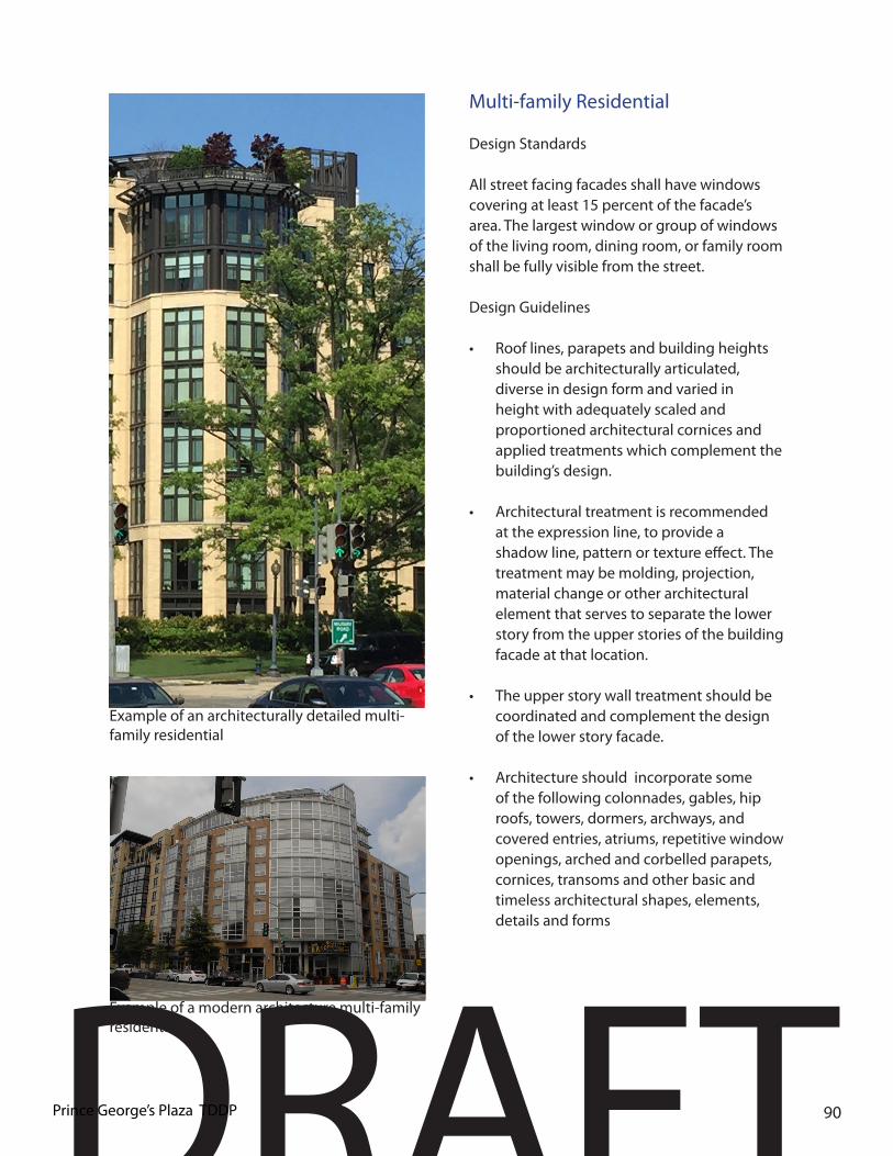
DRAFTPrince George’s Plaza TDDP 90
Multi-family Residential
Design Standards
All street facing facades shall have windows covering at least 15 percent of the facade’s area. The largest window or group of windows of the living room, dining room, or family room shall be fully visible from the street.
Design Guidelines
• Roof lines, parapets and building heights should be architecturally articulated, diverse in design form and varied in height with adequately scaled and proportioned architectural cornices and applied treatments which complement the building’s design.
• Architectural treatment is recommended at the expression line, to provide a shadow line, pattern or texture effect. The treatment may be molding, projection, material change or other architectural element that serves to separate the lower story from the upper stories of the building facade at that location.
• The upper story wall treatment should be coordinated and complement the design of the lower story facade.
• Architecture should incorporate some of the following colonnades, gables, hip roofs, towers, dormers, archways, and covered entries, atriums, repetitive window openings, arched and corbelled parapets, cornices, transoms and other basic and timeless architectural shapes, elements, details and forms
Example of a modern architecture multi-family residential
Example of an architecturally detailed multi-family residential

DRAFT91
Single-Family Attached, Townhomes and Detached
Dwellings
Design Standards
• There shall be not more than eight, nor less than three, dwelling units in any horizontal, continuous, attached group.
• The minimum width of dwellings in any continuous, attached group shall be at least 18 feet for townhouses.
• A minimum of seventy percent (70%) of all townhouse units in a development shall have a full front facade. Each building shall be deemed to have only one “front.”
• All street facing facades shall have win-dows covering at least 15 percent of the facade’s area. The largest window or group of windows of the living room, dining room, or family room should be fully visible from the street.
• The minimum rear yard setback shall be 10 to 15 feet from the rear lot line, except where alley-accessed garages or accessory buildings are provided, in which case the minimum rear yard setback shall be 5 feet.
• Where alleys are present garage access shall be located at rear of lots, if an alley is not present or not part of the proposal, garage door opening shall be recessed from the main single family attached or detached facade by a minimum of 10 feet.
• Alley entryways shall not front public streets when possible. If an alley entryway fronts a public street, the entryway should be mitigated with architectural comple-mentary wall or other source of architec-tural elements in order to reduce the view of the alley from the public view.
Design Guidelines
• Roof lines, parapets and building heights should be architecturally articulated, diverse in design form and varied in height with adequately scaled a proportioned architectural cornices and applied treat-ments which complement the building’s design.
• Architectural treatment is recommended at the expression line, to provide a shadow line, pattern or texture effect. The treat-ment may be molding, projection, material change or other architectural element that serves to separate the lower story from the upper stories of the building facade at that location.
• Side and rear walls should be articulated with windows, recesses, chimneys, or other architectural treatments. All end walls should have a minimum of four architec-tural features. Buildings on lots where end-walls are prominent (such as corner lots, lots visible from public spaces, streets, or because of topography or road curvature) should have additional endwall treatments consisting of architectural features in a bal-anced composition of durable materials.
• Attached groups containing units all the same width and design should be avoided, and within each attached group, attention should be given to the use of wider end units.
• The living space, which includes all inte-rior spaces except garages and unfinished basements or attic areas, should vary in sizes.
• One-family attached metropolitan dwell-ings should be designed with a single architecturally integrated “Front Wall.” 100 percent of the “Front Wall” should be con-structed of durable materials and contain distinctive architectural features, such as the following: colonnades, gables, hip roofs, towers, dormers, archways, and cov-ered entries, repetitive window openings, arched and corbelled parapets, cornices,

DRAFTPrince George’s Plaza TDDP 92
Main entrances and windows facing the street helping to create a sense of security (eyes of the street)
Residential fronting a street creating a sense of enclosure
transoms and other basic and timeless architectural shapes, elements, details and forms.
• Upper story wall treatment should be coor-dinated and complement the design of the lower story facade.

DRAFT93
“To affect the quality of a day, that is the highest of arts.”
- Henry David Thoreau, Walden (1854))

Tr a n s i t D i s t r i c t
The Maryland-National Capital Park and Planning CommissionPrince George’s County Planning DepartmentCommunity Planning Division
Draf t Standards and Guidel ines - July 13, 2015