transistor. bjt transistors: npn transistor pnp transistor sandwiching a p- type layer between two...
TRANSCRIPT

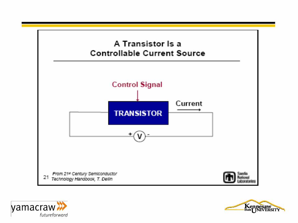
Transistor
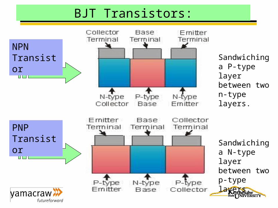
BJT Transistors:
NPN Transistor
PNP Transistor
Sandwiching a P-type layer between two n-type layers.
Sandwiching a N-type layer between two p-type layers.
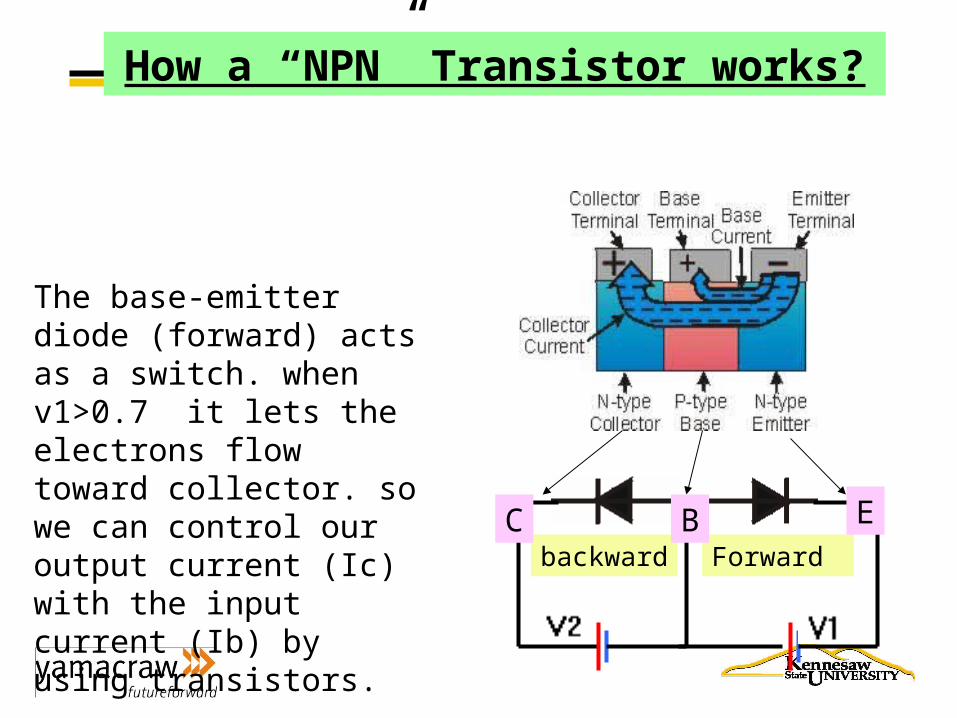
How a “NPN” Transistor works?
Forwardbackward
The base-emitter diode (forward) acts as a switch. when v1>0.7 it lets the electrons flow toward collector. so we can control our output current (Ic) with the input current (Ib) by using transistors.
C B E
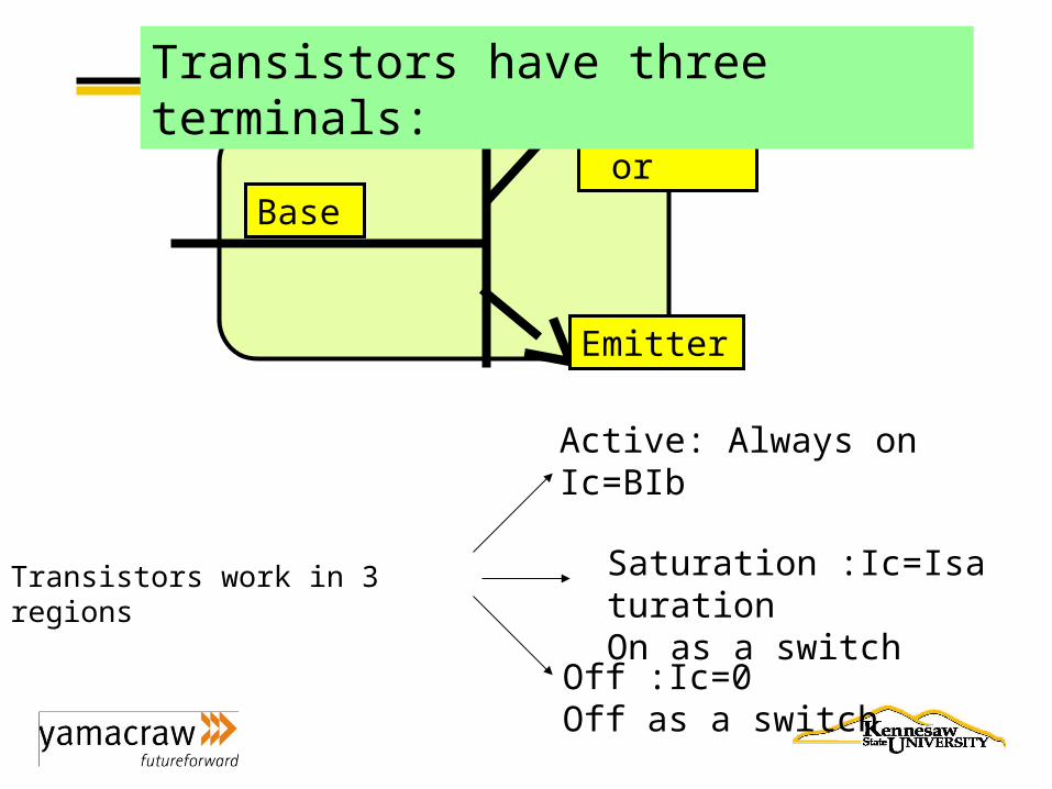
Collector
Emitter
Base
Transistors have three terminals:
Transistors work in 3 regions
Active: Always onIc=BIb
Saturation :Ic=IsaturationOn as a switch
Off :Ic=0Off as a switch
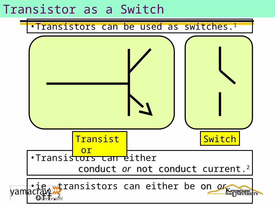
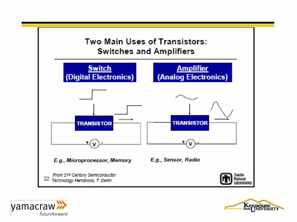
Transistor as a Switch• Transistors can be used as switches.1
• Transistors can eitherconductconduct or not conductnot conduct current.2
• ie, transistors can either be onon or offoff.2
Transistor Switch
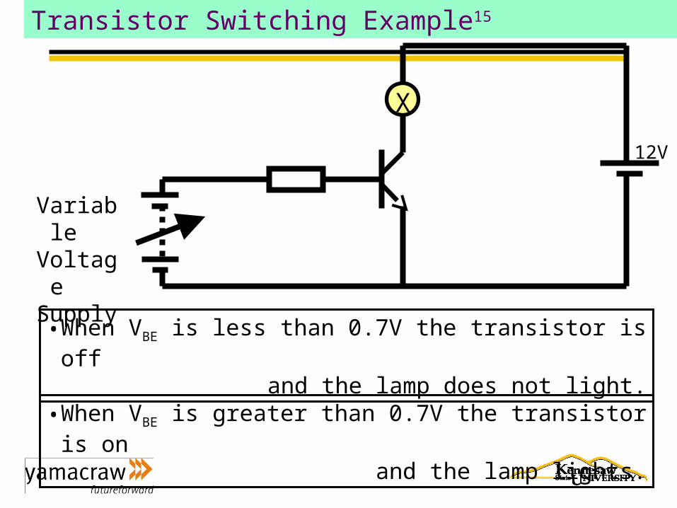
Transistor Switching Example15
• When VBE is less than 0.7V the transistor is offand the lamp does not light.
• When VBE is greater than 0.7V the transistor is onand the lamp lights.
X
VariableVoltageSupply
12V
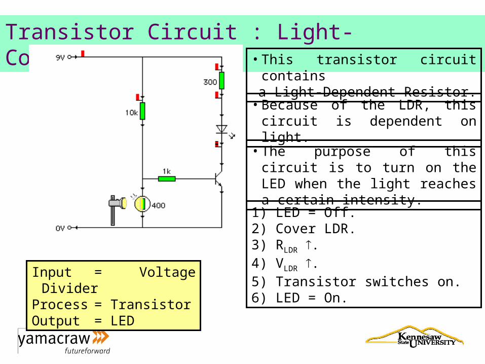
Transistor Circuit : Light-Controlled Circuit• This transistor circuit contains
a Light-Dependent Resistor.
• Because of the LDR, this circuit is dependent on light.
• The purpose of this circuit is to turn on the LED when the light reaches a certain intensity.
Input = Voltage DividerProcess = TransistorOutput = LED
1) LED = Off.2) Cover LDR.3) RLDR .4) VLDR .5) Transistor switches on.6) LED = On.
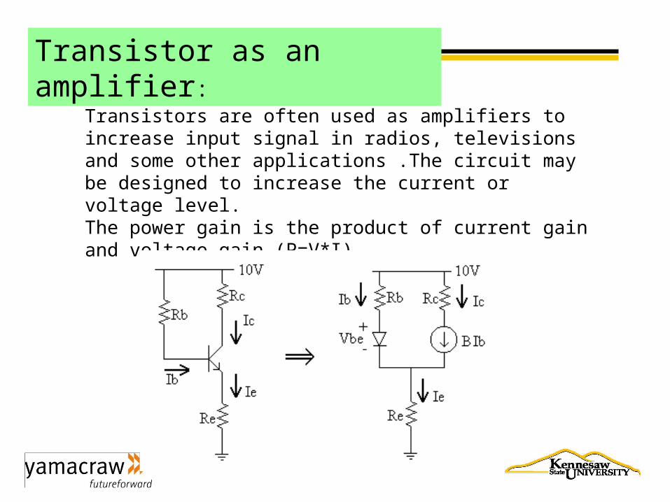
Transistor as an amplifier:
Transistors are often used as amplifiers to increase input signal in radios, televisions and some other applications .The circuit may be designed to increase the current or voltage level.The power gain is the product of current gain and voltage gain (P=V*I).
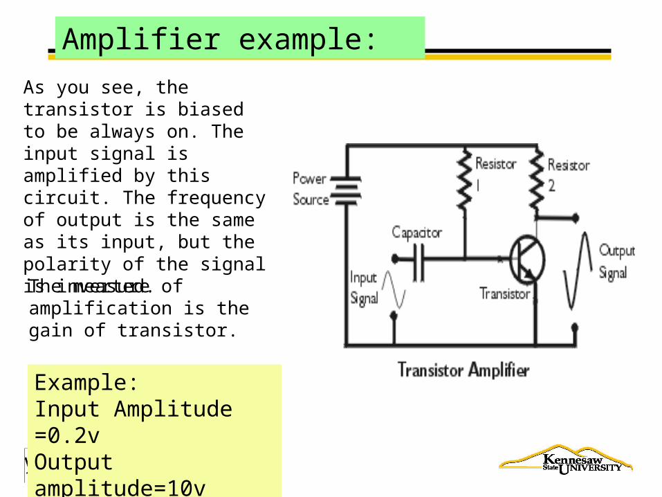
Amplifier example:
As you see, the transistor is biased to be always on. The input signal is amplified by this circuit. The frequency of output is the same as its input, but the polarity of the signal is inverted.
The measure of amplification is the gain of transistor.
Example:Input Amplitude =0.2vOutput amplitude=10vGain=10/0.2=50
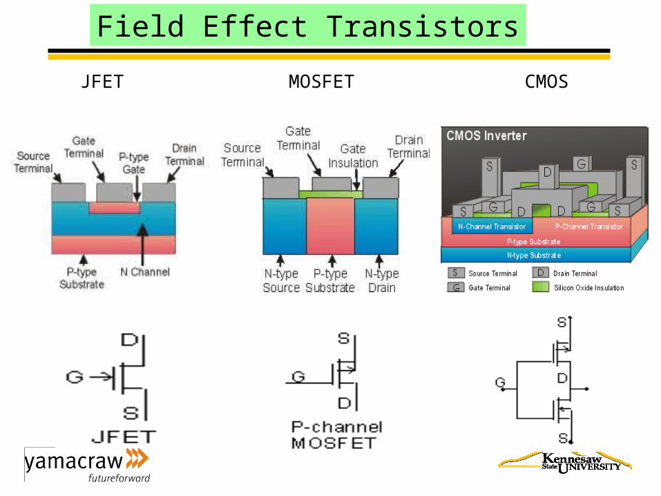
Field Effect Transistors
JFET MOSFET CMOS
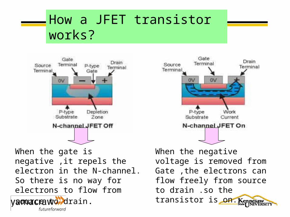
When the gate is negative ,it repels the electron in the N-channel. So there is no way for electrons to flow from
source to drain.
When the negative voltage is removed from Gate ,the electrons can flow freely from source to drain .so the transistor is on.
How a JFET transistor works?
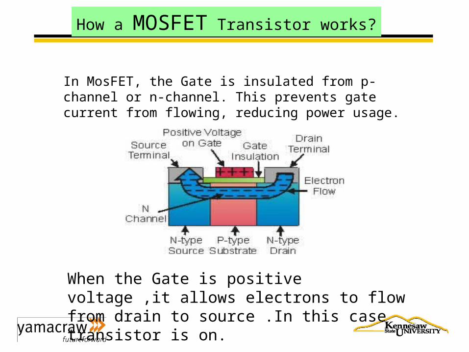
When the Gate is positive voltage ,it allows electrons to flow from drain to source .In this case transistor is on.
In MosFET, the Gate is insulated from p-channel or n-channel. This prevents gate current from flowing, reducing power usage.
How a MOSFET Transistor works?
How a CMOS transistor works?
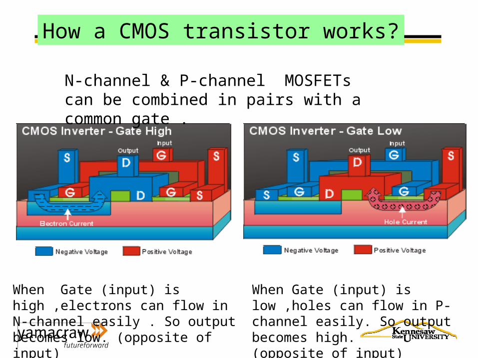
When Gate (input) is high ,electrons can flow in N-channel easily . So output becomes low. (opposite of input)
When Gate (input) is low ,holes can flow in P-channel easily. So output becomes high. (opposite of input)
N-channel & P-channel MOSFETs can be combined in pairs with a common gate .
SWITCHING
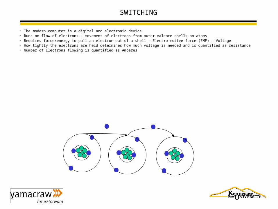
• The modern computer is a digital and electronic device.• Runs on flow of electrons - movement of electrons from outer valence shells on atoms• Requires force/energy to pull an electron out of a shell - Electro-motive force (EMF) - Voltage• How tightly the electrons are held determines how much voltage is needed and is quantified as resistance• Number of Electrons flowing is quantified as Amperes
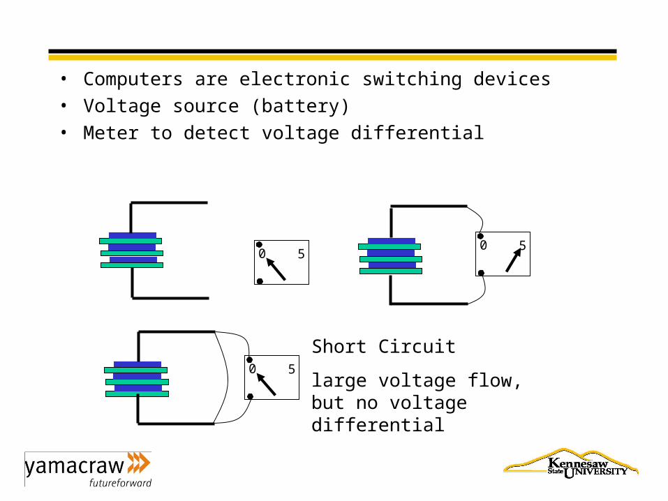
• Computers are electronic switching devices
• Voltage source (battery)
• Meter to detect voltage differential
0 50 5
0 5
Short Circuit
large voltage flow, but no voltage differential
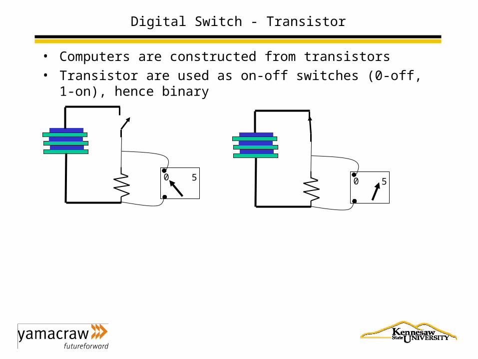
Digital Switch - Transistor
• Computers are constructed from transistors
• Transistor are used as on-off switches (0-off, 1-on), hence binary
0 5 0 5
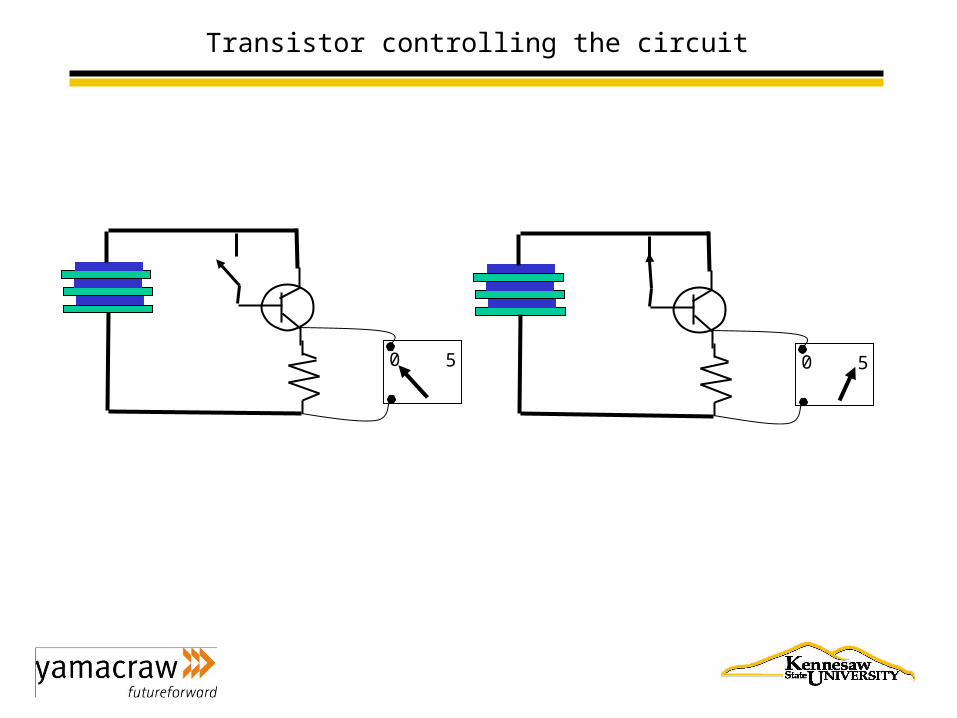
Transistor controlling the circuit
0 50 5
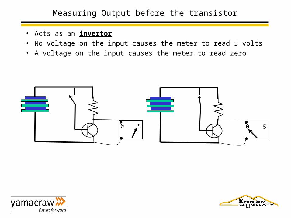
Measuring Output before the transistor
• Acts as an invertor
• No voltage on the input causes the meter to read 5 volts
• A voltage on the input causes the meter to read zero
0 5 0 5
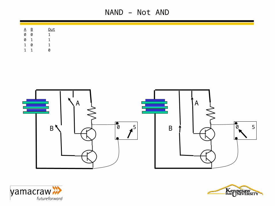
NAND – Not AND
A B Out0 0 10 1 11 0 11 1 0
0 5
A
B 0 5
A
B