training report1
DESCRIPTION
hjgftyfhgygdtrhgfTRANSCRIPT
SEQUENCE OF STRUCTURE WORK 1) Site Clearance
2) Demarcation of Site
3) Positioning of Central coordinate ie (0,0,0) as per grid plan
4) Surveying and layout
5) Excavation
6) Laying of PCC
7) Bar Binding and placement of foundation steel
8 ) Shuttering and Scaffolding
9) Concreting
10) Electrical and Plumbing
11) Deshuttering
12) Brickwork
13) Doors and windows frames along with lintels
14) Wiring for electrical purposes
15) Plastering
16) Flooring and tiling work
17) Painting
18) Final Completion and handing over the project
CONSTRUCTION PROCESS AND MATERIALS USED Site Clearance- The very first step is site clearance which involves removal of grass and
vegetation along with any other objections which might be there in the site location.
Demarcation of Site- The whole area on which construction is to be done is marked so as to
identify the construction zone. In our project, a plot of 450*350 sq ft was chosen and the
respective marking was done.
Positioning of Central coordinate and layout- The centre point was marked with the help of a
thread and plumb bob as per the grid drawing. With respect to this center point, all the other
points of columns were to be decided so its exact position is very critical.
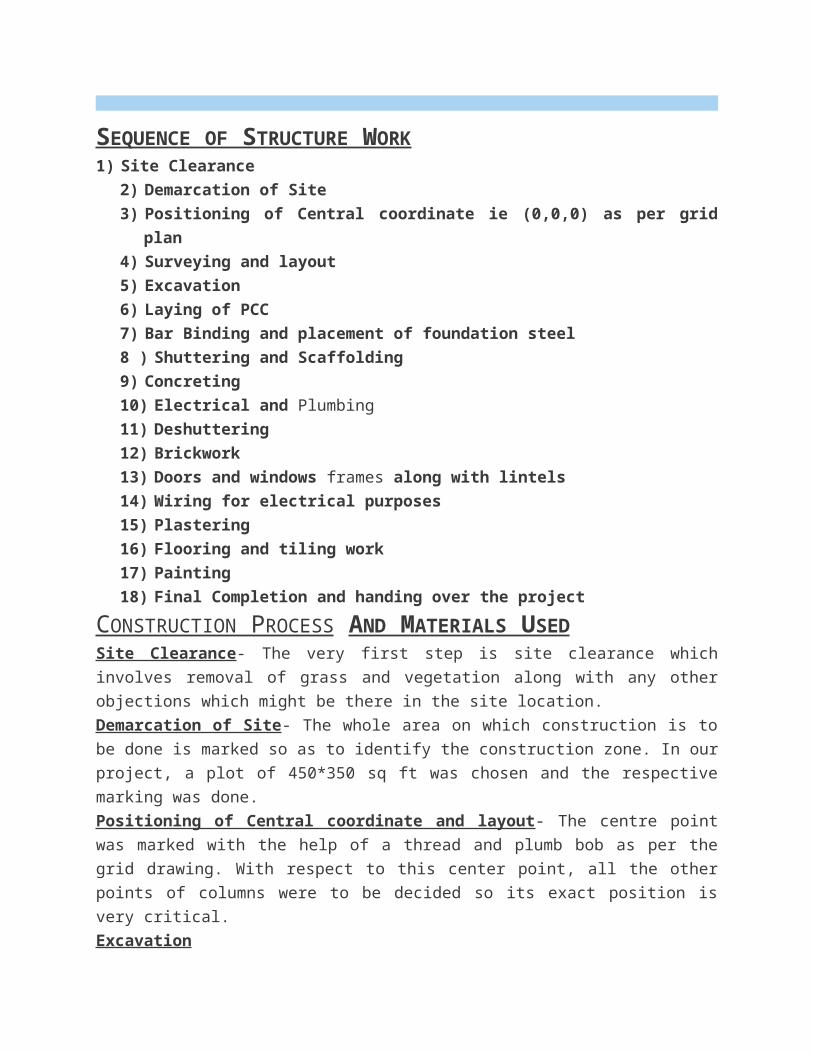
Excavation
Excavation was carried out both manually as well as mechanically. Normally 1-2 earth
excavators (JCB’s) were used for excavating the soil. Adequate precautions are taken to see that
the excavation operations do not damage the adjoining structures. Excavation is carried out
providing adequate side slopes and dressing of excavation bottom. The soil present beneath the
surface was too clayey so it was dumped and was not used for back filling. The filling is done in
layer not exceeding 20 cm layer and than its compacted. Depth of excavation was 5’4” from
Ground Level.
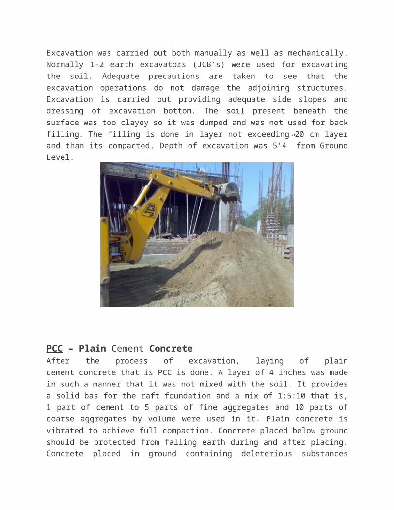
PCC – Plain Cement ConcreteAfter the process of excavation, laying of plain cement concrete that is PCC is done. A layer of 4
inches was made in such a manner that it was not mixed with the soil. It provides a solid bas for
the raft foundation and a mix of 1:5:10 that is, 1 part of cement to 5 parts of fine aggregates and
10 parts of coarse aggregates by volume were used in it. Plain concrete is vibrated to achieve full
compaction. Concrete placed below ground should be protected from falling earth during and
after placing. Concrete placed in ground containing deleterious substances should be kept free
from contact with such a ground and with water draining there from during placing and for a
period of seven days. When joint in a layer of concrete are unavoidable, and end is sloped at an
angle of 30 and junctions of different layers break joint in laying upper layer of concrete. The
lower surface is made rough and clean watered before upper layer is laid.
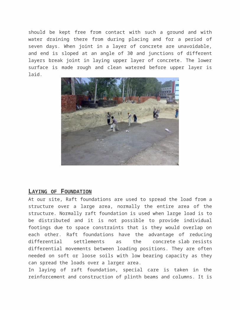
LAYING OF FOUNDATION At our site, Raft foundations are used to spread the load from a structure over a large area,
normally the entire area of the structure. Normally raft foundation is used when large load is to
be distributed and it is not possible to provide individual footings due to space constraints that is
they would overlap on each other. Raft foundations have the advantage of reducing differential
settlements as the concrete slab resists differential movements between loading positions. They
are often needed on soft or loose soils with low bearing capacity as they can spread the loads
over a larger area.
In laying of raft foundation, special care is taken in the reinforcement and construction of plinth
beams and columns. It is the main portion on which ultimately whole of the structure load is to
come. So a slightest error can cause huge problems and therefore all this is checked and passed
by the engineer in charge of the site.
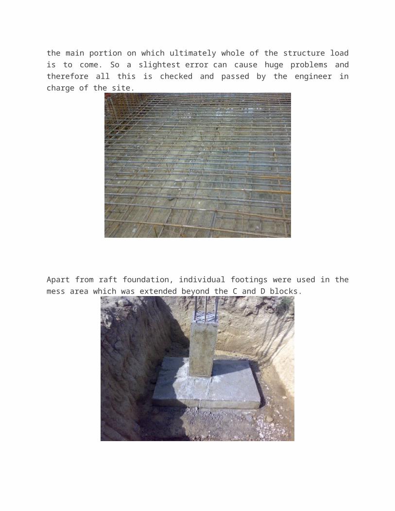
Apart from raft foundation, individual footings were used in the mess area which was extended
beyond the C and D blocks.
CEMENT
Portland cement is composed of calcium silicates and aluminate and aluminoferrite It is obtained
by blending predetermined proportions limestone clay and other minerals in small quantities
which is pulverized and heated at high temperature – around 1500 deg centigrade to produce
‘clinker’. The clinker is then ground with small quantities of gypsum to produce a fine powder
called Ordinary Portland Cement (OPC). When mixed with water, sand and stone, it combines
slowly with the water to form a hard mass called concrete. Cement is a hygroscopic material
meaning that it absorbs moisture In presence of moisture it undergoes chemical reaction termed
as hydration. Therefore cement remains in good condition as long as it does not come in contact
with moisture. If cement is more than three months old then it should be tested for its strength
before being taken into use.
The Bureau of Indian Standards (BIS) has classified OPC in three different grades The
classification is mainly based on the compressive strength of cement-sand mortar cubes
of face area 50 cm2 composed of 1 part of cement to 3 parts of standard sand by weight with a
water-cement ratio arrived at by a specified procedure. The grades are
(i) 33 grade
(ii) 43 grade
(iii) 53 grade
The grade number indicates the minimum compressive strength of cement sand mortar in
N/mm2 at 28 days, as tested by above mentioned procedure.
Portland Pozzolana Cement (PPC) is obtained by either intergrinding a pozzolanic material with
clinker and gypsum, or by blending ground pozzolana with Portland cement. Nowadays good
quality fly ash is available from Thermal Power Plants, which are processed and used in
manufacturing of PPC.
ADVANTAGES OF USING PORTLAND POZZOLANA CEMENT OVER OPC Pozzolana combines with lime and alkali in cement when water is added and forms compounds
which contribute to strength, impermeability and sulphate resistance. It also contributes to
workability, reduced bleeding and controls destructive expansion from alkali-aggregate reaction.
It reduces heat of hydration thereby controlling temperature differentials, which causes thermal
strain and resultant cracking n mass concrete structures like dams. The colour of PPC comes
from the colour of the pozzolanic material used. PPC containing fly ash as a pozzolana will
invariably be slightly different colour than the OPC.One thing should be kept in mind that is the
quality of cement depends upon the raw materials used and the quality control measures adopted
during its manufacture, and not on the shade of the cement. The cement gets its colour from the
nature and colour of raw materials used, which will be different from factory to factory, and may
even differ in the different batches of cement produced in a factory. Further, the colour of the
finished concrete is affected also by the colour of the aggregates, and to a lesser extent by the
colour of the cement. Preference for any cement on the basis of colour alone is technically
misplaced.
SETTLING OF CEMENT
When water is mixed with cement, the paste so formed remains pliable and plastic for a short
time. During this period it is possible to disturb the paste and remit it without any deleterious
effects. As the reaction between water and cement continues, the paste loses its plasticity. This
early period in the hardening of cement is referred to as ‘setting’ of cement.
INITIAL AND FINAL SETTING TIME OF CEMENT
Initial set is when the cement paste loses its plasticity and stiffens considerably. Final set is the
point when the paste hardens and can sustain some minor load. Both are arbitrary points and
these are determined by Vicat needle penetration resistance
Slow or fast setting normally depends on the nature of cement. It could also be due to extraneous
factors not related to the cement. The ambient conditions play an important role. In hot weather,
the setting is faster, in cold weather, setting is delayed Some types of salts, chemicals, clay, etc if
inadvertently get mixed with the sand, aggregate and water could accelerate or delay the setting
of concrete.
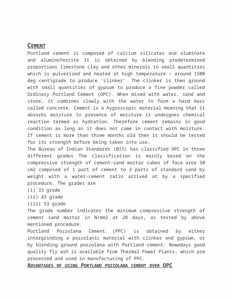
STORAGE OF CEMENT
It needs extra care or else can lead to loss not only in terms of financial loss but also in terms of
loss in the quality. Following are the don’t that should be followed -
(i) Do not store bags in a building or a godown in which the walls, roof and floor are not
completely weatherproof.
(ii) Do not store bags in a new warehouse until the interior has thoroughly dried out.
(iii) Do not be content with badly fitting windows and doors, make sure they fit properly and
ensure that they are kept shut.
(iv) Do not stack bags against the wall. Similarly, don’t pile them on the floor unless it is a dry
concrete floor. If not, bags should be stacked on wooden planks or sleepers.
(v) Do not forget to pile the bags close together
(vi) Do not pile more than 15 bags high and arrange the bags in a header-and-stretcher fashion.
(vii) Do not disturb the stored cement until it is to be taken out for use.
(viii) Do not take out bags from one tier only. Step back two or three tiers.
(ix) Do not keep dead storage. The principle of first-in first-out should be followed in removing
bags.
(x) Do not stack bags on the ground for temporary storage at work site. Pile them on a raised, dry
platform and cover with tarpaulin or polythene sheet.
COARSE AGGREGATE Coarse aggregate for the works should be river gravel or crushed stone .It should be hard, strong,
dense, durable, clean, and free from clay or loamy admixtures or quarry refuse or vegetable
matter. The pieces of aggregates should be cubical, or rounded shaped and should have granular
or crystalline or smooth (but not glossy) non-powdery surfaces.Aggregates should be properly
screened and if necessary washed clean before use.
Coarse aggregates containing flat, elongated or flaky pieces or mica should be rejected. The
grading of coarse aggregates should be as per specifications of IS-383.
After 24-hrs immersion in water, a previously dried sample of the coarse aggregate should not gain in
weight more than 5%.
Aggregates should be stored in such a way as to prevent segregation of sizes and avoid
contamination with fines.
Depending upon the coarse aggregate color, there quality can be determined as:
Black => very good qualityBlue => goodWhitish =>bad quality
FINE AGGREGATE
Aggregate which is passed through 4.75 IS Sieve is termed as fine aggregate. Fine aggregate is
added to concrete to assist workability and to bring uniformity in mixture. Usually, the natural
river sand is used as fine aggregate. Important thing to be considered is that fine aggregates
should be free from coagulated lumps.
Grading of natural sand or crushed stone i.e. fine aggregates shall be such that not more than 5
percent shall exceed 5 mm in size, not more than 10% shall IS sieve No. 150 not less than 45%
or more than 85% shall pass IS sieve No. 1.18 mm and not less than 25% or more than 60% shall
pass IS sieve No. 600 micron.
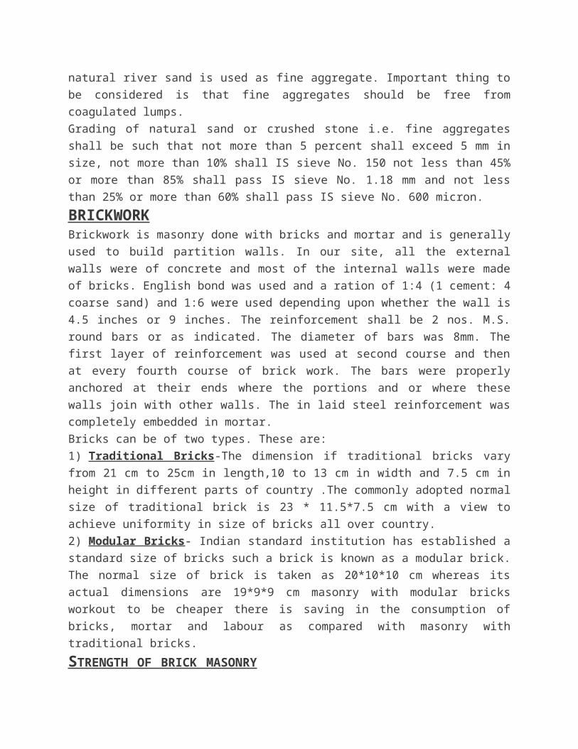
BRICKWORKBrickwork is masonry done with bricks and mortar and is generally used to build partition walls.
In our site, all the external walls were of concrete and most of the internal walls were made of
bricks. English bond was used and a ration of 1:4 (1 cement: 4 coarse sand) and 1:6 were used
depending upon whether the wall is 4.5 inches or 9 inches. The reinforcement shall be 2 nos.
M.S. round bars or as indicated. The diameter of bars was 8mm. The first layer of reinforcement
was used at second course and then at every fourth course of brick work. The bars were properly
anchored at their ends where the portions and or where these walls join with other walls. The in
laid steel reinforcement was completely embedded in mortar.
Bricks can be of two types. These are:
1) Traditional Bricks-The dimension if traditional bricks vary from 21 cm to 25cm in length,10
to 13 cm in width and 7.5 cm in height in different parts of country .The commonly adopted
normal size of traditional brick is 23 * 11.5*7.5 cm with a view to achieve uniformity in size of
bricks all over country.
2) Modular Bricks- Indian standard institution has established a standard size of bricks such a
brick is known as a modular brick. The normal size of brick is taken as 20*10*10 cm whereas its
actual dimensions are 19*9*9 cm masonry with modular bricks workout to be cheaper there is
saving in the consumption of bricks, mortar and labour as compared with masonry with
traditional bricks.
STRENGTH OF BRICK MASONRY The permissible compressive stress in brick masonry depends upon the following factors:
1. Type and strength of brick.
2. Mix of motor.
3. Size and shape of masonry construction.
The strength of brick masonry depends upon the strength of bricks used in the masonry
construction. The strength of bricks depends upon the nature of soil used for making and the
method adopted for molding and burning of bricks .since the nature of soil varies from region to
region ,the average strength of bricks varies from as low as 30kg/sq cm to 150 kg /sq cm the
basic compressive stress are different crushing strength.
There are many checks that can be applied to see the quality of bricks used on the site.Normally
the bricks are tested for Compressive strength, water absorption, dimensional tolerances and
efflorescence. However at small construction sites the quality of bricks can be assessed based on
following, which is prevalent in many sites.
• Visual check – Bricks should be well burnt and of uniform size and color.
• Striking of two bricks together should produce a metallic ringing sound.
• It should have surface so hard that can’t be scratched by the fingernails.
• A good brick should not break if dropped in standing position from one metre above ground
level.
• A good brick shouldn’t absorb moisture of more than 15-20% by weight, when soaked in water
For example; a good brick of 2 kg shouldn’t weigh more than 2.3 to 2.4 kg if immersed in
water for 24 hours.
PRECAUTIONS TO BE TAKEN IN BRICK MASONRY WORK
• Bricks should be soaked in water for adequate period so that the water penetrates
to its full thickness. Normally 6 to 8 hours of wetting is sufficient.
• A systematic bond must be maintained throughout the brickwork. Vertical joints
shouldn’t be continuous but staggered.
• The joint thickness shouldn’t exceed 1 cm. It should be thoroughly filled with the
cement mortar 1:4 to 1:6 (Cement: Sand by volume)
• All bricks should be placed on their bed with frogs on top (depression on top of the
brick for providing bond with mortar).
• Thread, plumb bob and spirit level should be used for alignment, verticality and
horizontality of construction.
• Joints should be raked and properly finished with trowel or float, to provide good bond.
• A maximum of one metre wall height should be constructed in a day.
• Brickwork should be properly cured for at least 10 days
REINFORCEMENTSteel reinforcements are used, generally, in the form of bars of circular cross section in concrete
structure. They are like a skeleton in human body. Plain concrete without steel or any other
reinforcement is strong in compression but weak in tension. Steel is one of the best forms of
reinforcements, to take care of those stresses and to strengthen concrete to bear all kinds of loads
Mild steel bars conforming to IS: 432 (Part I) and Cold-worked steel high strength deformed bars
conforming to IS: 1786 (grade Fe 415 and grade Fe 500, where 415 and 500 indicate yield
stresses 415 N/mm2 and 500 N/mm2 respectively) are commonly used. Grade Fe 415 is being
used most commonly nowadays. This has limited the use of plain mild steel bars because of
higher yield stress and bond strength resulting in saving of steel quantity. Some companies have
brought thermo mechanically treated (TMT) and corrosion resistant steel (CRS) bars with added
features.
Bars range in diameter from 6 to 50 mm. Cold-worked steel high strength deformed bars start
from 8 mm diameter. For general house constructions, bars of diameter 6 to 20 mm are used
Transverse reinforcements are very important. They not only take care of structural requirements
but also help main reinforcements to remain in desired position. They play a very significant role
while abrupt changes or reversal of stresses like earthquake etc.
They should be closely spaced as per the drawing and properly tied to the main/longitudinal
reinforcement
TERMS USED IN REINFORCEMENT
BAR-BENDING-SCHEDULE
Bar-bending-schedule is the schedule of reinforcement bars prepared in advance before cutting
and bending of rebars. This schedule contains all details of size, shape and dimension of rebars to
be cut.
LAP LENGTH
Lap length is the length overlap of bars tied to extend the reinforcement length.. Lap length about
50 times the diameter of the bar is considered safe. Laps of neighboring bar lengths should be
staggered and should not be provided at one level/line. At one cross section, a maximum of 50%
bars should be lapped. In case, required lap length is not available at junction because of space
and other constraints, bars can be joined with couplers or welded (with correct choice of method
of welding).
ANCHORAGE LENGTH
This is the additional length of steel of one structure required to be inserted in other at the
junction. For example, main bars of beam in column at beam column junction, column bars in
footing etc. The length requirement is similar to the lap length mentioned in previous question or
as per the design instructions
COVER BLOCK Cover blocks are placed to prevent the steel rods from touching the shuttering plates and there by
providing a minimum cover and fix the reinforcements as per the design drawings. Sometimes it
is commonly seen that the cover gets misplaced during the concreting activity. To prevent this,
tying of cover with steel bars using thin steel wires called binding wires (projected from cover
surface and placed during making or casting of cover blocks) is recommended. Covers should be
made of cement sand mortar (1:3). Ideally, cover should have strength similar to the surrounding
concrete, with the least perimeter so that chances of water to penetrate through periphery will be
minimized. Provision of minimum covers as per the Indian standards for durability of the whole
structure should be ensured.
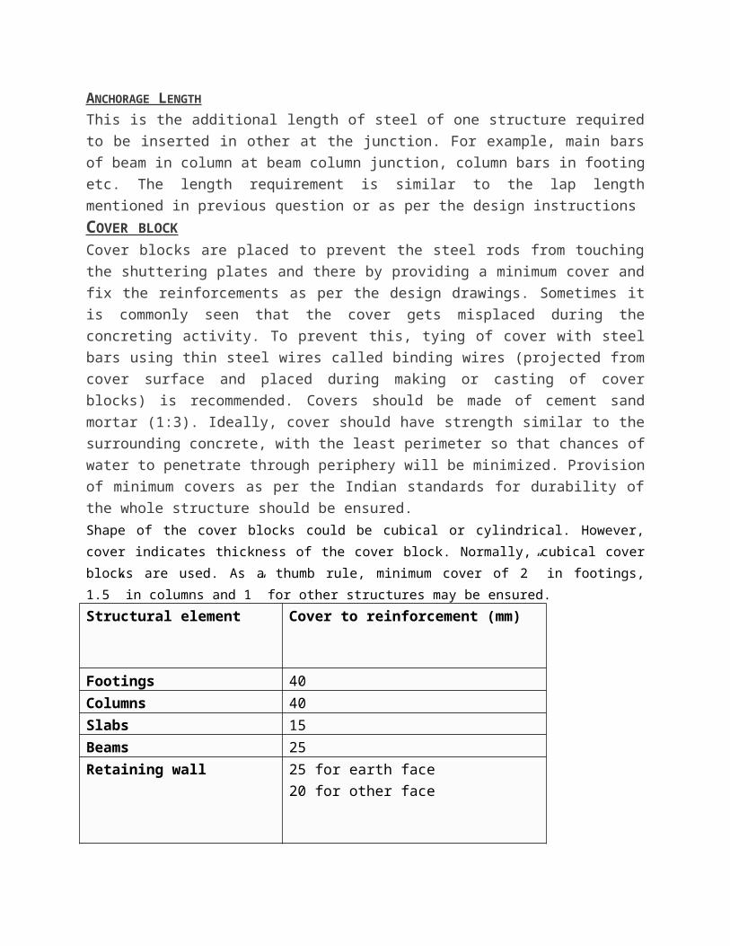
Shape of the cover blocks could be cubical or cylindrical. However, cover indicates thickness of the cover
block. Normally, cubical cover blocks are used. As a thumb rule, minimum cover of 2” in footings, 1.5” in
columns and 1” for other structures may be ensured.
Structural element Cover to reinforcement (mm)
Footings 40
Columns 40
Slabs 15
Beams 25
Retaining wall 25 for earth face
20 for other face
THINGS TO NOTE
Reinforcement should be free from loose rust, oil paints, mud etc. it should be cut, bent and fixed
properly. The reinforcement shall be placed and maintained in position by providing proper
cover blocks, spacers, supporting bars, laps etc. Reinforcements shall be placed and tied such
that concrete placement is possible without segregation, and compaction possible by an
immersion vibrator.
For any steel reinforcement bar, weight per running meter is equal to d*d/162 Kg, where d is
diameter of the bar in mm. For example, 10 mm diameter bar will weigh 10×10/162 = 0.617
Kg/m
Three types of bars were used in reinforcement of a slab. These include straight bars, crank bar
and an extra bar. The main steel is placed in which the straight steel is binded first, then the
crank steel is placed and extra steel is placed in the end. The extra steel comes over the support
while crank is encountered at distance of ¼(1-distance between the supports) from the
surroundings supports.
For providing nominal cover to the steel in beam, cover blocks were used which were made of
concrete and were casted with a thin steel wire in the center which projects outward. These keep
the reinforcement at a distance from bottom of shuttering. For maintaining the gap between the
main steel and the distribution steel, steel chairs are placed between them
SHUTTERING AND SCAFFOLDINGDEFINITION
The term ‘SHUTTERING’ or ‘FORMWORK’ includes all forms, moulds, sheeting, shuttering
planks, walrus, poles, posts, standards, leizers, V-Heads, struts, and structure, ties, prights,
walling steel rods, bolts, wedges, and all other temporary supports to the concrete during the
process of sheeting.
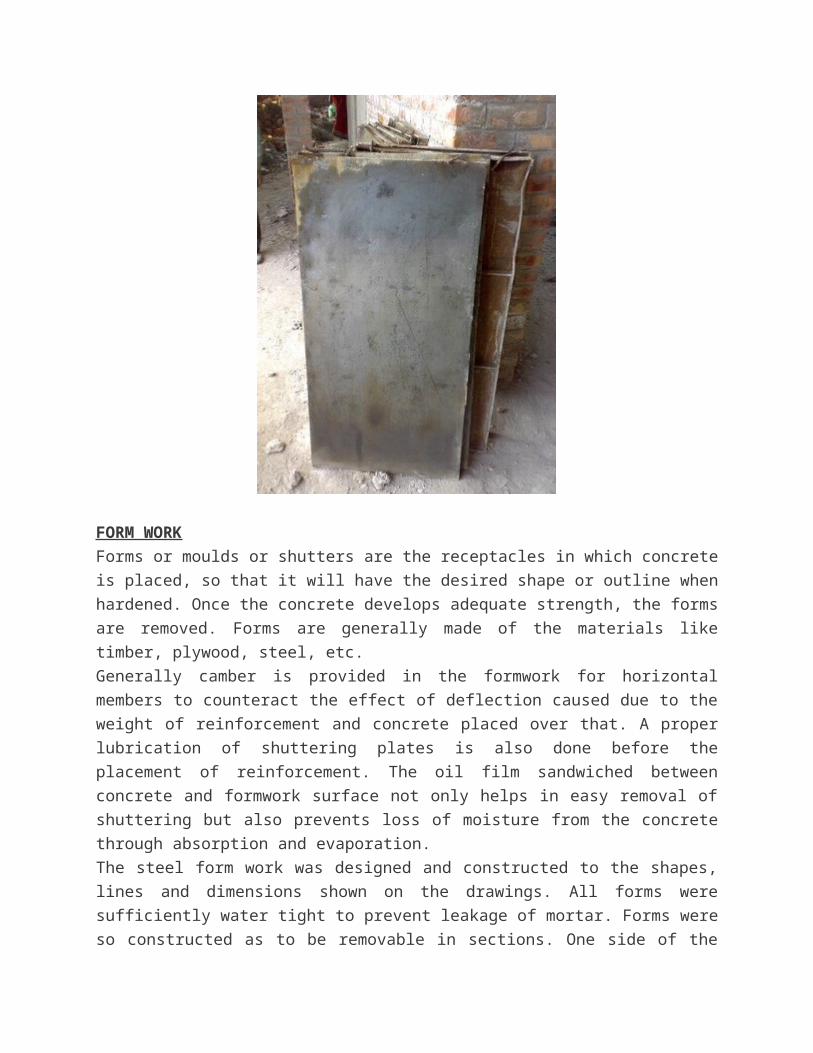
FORM WORK
Forms or moulds or shutters are the receptacles in which concrete is placed, so that it will have
the desired shape or outline when hardened. Once the concrete develops adequate strength, the
forms are removed. Forms are generally made of the materials like timber, plywood, steel, etc.
Generally camber is provided in the formwork for horizontal members to counteract the effect of
deflection caused due to the weight of reinforcement and concrete placed over that. A proper
lubrication of shuttering plates is also done before the placement of reinforcement. The oil film
sandwiched between concrete and formwork surface not only helps in easy removal of shuttering
but also prevents loss of moisture from the concrete through absorption and evaporation.
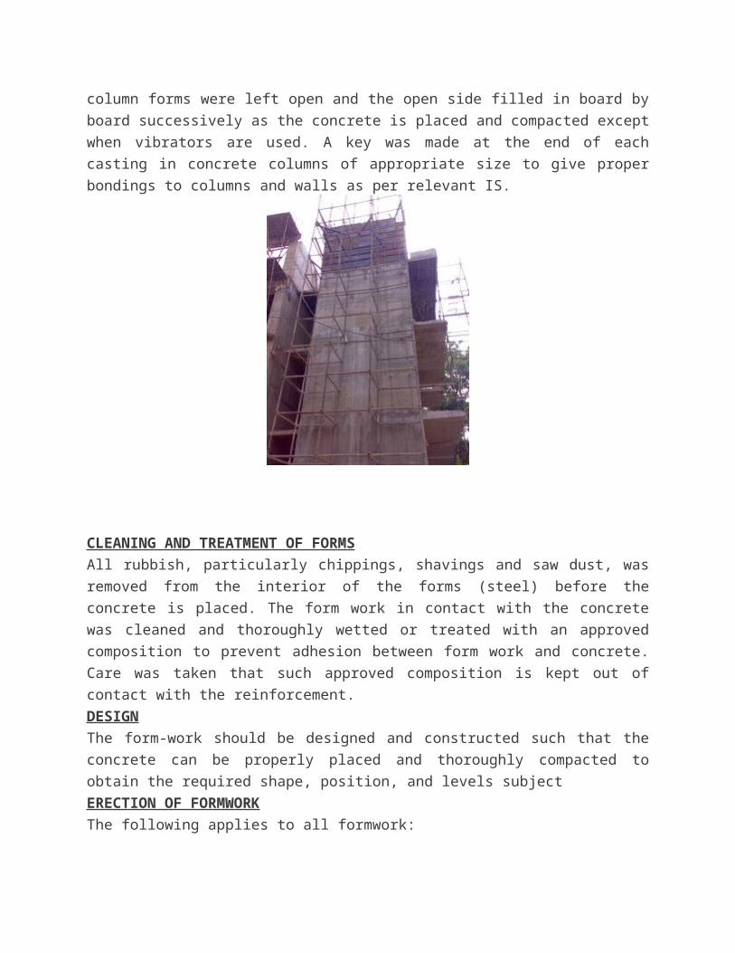
The steel form work was designed and constructed to the shapes, lines and dimensions shown on
the drawings. All forms were sufficiently water tight to prevent leakage of mortar. Forms were
so constructed as to be removable in sections. One side of the column forms were left open and
the open side filled in board by board successively as the concrete is placed and compacted
except when vibrators are used. A key was made at the end of each casting in concrete columns
of appropriate size to give proper bondings to columns and walls as per relevant IS.
CLEANING AND TREATMENT OF FORMS
All rubbish, particularly chippings, shavings and saw dust, was removed from the interior of the
forms (steel) before the concrete is placed. The form work in contact with the concrete was
cleaned and thoroughly wetted or treated with an approved composition to prevent adhesion
between form work and concrete. Care was taken that such approved composition is kept out of
contact with the reinforcement.
DESIGN
The form-work should be designed and constructed such that the concrete can be properly placed
and thoroughly compacted to obtain the required shape, position, and levels subject
ERECTION OF FORMWORK
The following applies to all formwork:
a) Care should be taken that all formwork is set to plumb and true to line and level.
b) When reinforcement passes through the formwork care should be taken to ensure close
fitting joints against the steel bars so as to avoid loss of fines during the compaction of
concrete.
c) If formwork is held together by bolts or wires, these should be so fixed that no iron is
exposed on surface against which concrete is to be laid.
d) Provision is made in the shuttering for beams, columns and walls for a port hole of
convenient size so that all extraneous materials that may be collected could be
removed just prior to concreting.
e) Formwork is so arranged as to permit removal of forms without jarring the concrete.
Wedges, clamps, and bolts should be used where practicable instead of nails.
f) Surfaces of forms in contact with concrete are oiled with a mould oil of approved
quality. The use of oil, which darkens the surface of the concrete, is not allowed. Oiling
is done before reinforcement is placed and care taken that no oil comes in contact with
the reinforcement while it is placed in position. The formwork is kept thoroughly wet
during concreting and the whole time that it is left in place.
Immediately before concreting is commenced, the formwork is carefully examined to
ensure the following:
a) Removal of all dirt, shavings, sawdust and other refuse by brushing and washing.
b) The tightness of joint between panels of sheathing and between these and any hardened core.
c) The correct location of tie bars bracing and spacers, and especially connections of
bracing.
d) That all wedges are secured and firm in position.
e) That provision is made for traffic on formwork not to bear directly on reinforcement
steel.
VERTICALITY OF THE STUCTURE
All the outer columns of the frame were checked for plumb by plumb-bob as the work proceeds
to upper floors. Internal columns were checked by taking measurements from outer row of
columns for their exact position. Jack were used to lift the supporting rods called props
STRIPPING TIME OR REMOVAL OF FORMWORK
Forms were not struck until the concrete has attained a strength at least twice the stress to which
the concrete may be subjected at the time of removal of form work. The strength referred is that
of concrete using the same cement and aggregates with the same proportions and cured under
conditions of temperature and moisture similar to those existing on the work. Where so required,
form work was left longer in normal circumstances
Form work was removed in such a manner as would not cause any shock or vibration that would
damage the concrete. Before removal of props, concrete surface was exposed to ascertain that the
concrete has sufficiently hardened. Where the shape of element is such that form work has re-
entrant angles, the form work was removed as soon as possible after the concrete has set, to
avoid shrinkage cracking occurring due to the restraint imposed. As a guideline, with
temperature above 20 degree following time limits should be followed:
Structural Component Age
Footings 1 day
Sides of beams, columns, lintels, wall 2 days
Underside of beams spanning less than 6m 14 days
Underside of beams spanning over 6m 21 days
Underside of slabs spanning less than 4m 7 days
Underside of slabs spanning more than 4m 14 days
Flat slab bottom 21 days