traffic engineering with mpls and qos - diva portal828380/fulltext02.pdf · traffic engineering...
TRANSCRIPT

1
Master Thesis Electrical Engineering Thesis no: MSEE-2009-xx Month Year
School of Engineering Blekinge Institute of Technology SE-371 79 Karlskrona Sweden
Traffic Engineering with MPLS and QOS
Imran Ikram

2
Contact Information: Author(s): Imran Ikram Address: 68 ILFORD ESSEX, IG1 3NG, CANTERBURY AVENUES. UK E-mail: [email protected] Phone: 00445601569409
University advisor(s): Alexandru Popescu Department of Telecommunication Systems Address: Blekinge Institute of Technology, SE-371 79 Karlskrona, Sweden Mobile #: 0046733124956 E-post: [email protected]
University Examiner(s): Adrian Popescu Department of Telecommunication Systems
E-mail: [email protected] Phone: 0046455385659 Mobile: 0046708754803
School of Engineering Blekinge Institute of Technology SE-371 79 Karlskrona Sweden
Internet : www.bth.se/tek Phone : +46 457 38 50 00 Fax : +46457279 14

3
Table of Contents
TRAFFIC ENGINEERING WITH MPLS AND QOS ..................................................................... 1
TABLE OF FIGURES ......................................................................................................................... 6
ABSTRACT .......................................................................................................................................... 7
1 CHAPTER 1 ................................................................................................................................. 9
1.1 INTRODUCTION ................................................................................................................ 9 1.2 THE BIGGER PICTURE .......................................................................................................... 10 1.3 CONVENTIONAL IP NETWORKS ............................................................................................ 11
1.4 BENEFIT OF MPLS ............................................................................................................... 13 1.5 OUTLINE ........................................................................................................................... 13
2 CHAPTER 2 ............................................................................................................................... 15
2.1 BACKGROUND ................................................................................................................ 15 2.2 MPLS OBJECTIVE: ........................................................................................................... 15 2.3 MPLS CONCEPTS: ............................................................................................................ 15 2.4 MPLS APPLICATION: ...................................................................................................... 16
2.4.1 Connection Oriented QOS support ................................................................................. 16
2.4.2 Traffic Engineering (TE) ................................................................................................ 16
2.4.3 Virtual Private Networks (VPNs) .................................................................................... 17
2.4.4 Multi-protocol Support ................................................................................................... 18
2.5 MPLS OVERVIEW ................................................................................................................ 18 2.6 MPLS WORKING ................................................................................................................. 18 2.7 CONTROLLED DRIVEN ......................................................................................................... 20 2.8 ER-LSP ............................................................................................................................... 21
2.9 MPLS NETWORK ARCHITECTURE COMPONENTS, OPERATIONS, PROTOCOLS STACK
ARCHITECTURE AND APPLICATIONS .................................................................................................. 21
2.9.2 MPLS Node Basic Architecture ...................................................................................... 22
2.9.3 MPLS Header ................................................................................................................. 23
2.9.4 MPLS Label .................................................................................................................... 24
2.9.5 LSRs and LERs ............................................................................................................... 25
2.9.6 FEC ................................................................................................................................. 25
2.9.7 LSP.................................................................................................................................. 25
2.10 LABEL DISTRIBUTION .......................................................................................................... 26 2.11 MPLS LOOP DETECTION AND PREVENTION .......................................................................... 26
2.11.1 Frame mode ................................................................................................................ 26
2.11.2 Data Plane mode ........................................................................................................ 26
2.11.3 Frame mode: control plane loop prevention ............................................................. 27
3 CHAPTER 3 ............................................................................................................................... 30
3.1 MPLS TRAFFIC ENGINEERING (MPLS-TE) ................................................................. 30 3.1.1 What is QOS? ................................................................................................................. 30
3.1.2 Best-effort Service ........................................................................................................... 30
3.1.3 Link Congestion .............................................................................................................. 31
3.2 TRAFFIC ENGNEERING IN MPLS .................................................................................. 32
3.2.1 Introduction .................................................................................................................... 32
3.2.2 Traffic Engineering ......................................................................................................... 32
3.2.3 Link Congestion .............................................................................................................. 32
3.2.4 Load Balancing ............................................................................................................... 33
3.2.5 Link protection ................................................................................................................ 34
3.3 BENEFITS OF MPLS-TE ....................................................................................................... 35
4
3.4 MPLS-TE WORKING ........................................................................................................... 36 3.4.1 Traffic Oriented .............................................................................................................. 40
3.4.2 Resource oriented ........................................................................................................... 40
3.5 TRAFFIC AND RESOURCE CONTROL ..................................................................................... 41
3.6 LIMITATIONS OF CURRENT IGP CONTROL MECHANISM IN ACCORDANCE WITH TE ............. 41
4 CHAPTER NO 4 ........................................................................................................................ 44
4.1 LABEL DISTRIBUTON PROTOCOL ............................................................................... 44
4.1.1 DISCOVERY ................................................................................................................... 45
4.2 LABEL MERGING ................................................................................................................. 46 4.3 LABEL RETENTION ............................................................................................................... 46
4.3.1 Conservative ................................................................................................................... 46
4.3.2 Liberal ............................................................................................................................ 46
4.4 LABEL DISTRIBUTION CONTROL MODE ............................................................................... 46
4.4.1 Independent..................................................................................................................... 46
4.4.2 Ordered ........................................................................................................................... 46
4.5 LABEL BINDING AND ASSIGNMENT...................................................................................... 47
4.5.1 Unsolicited downstream label binding ........................................................................... 47
4.5.2 Downstream on demand label binding ........................................................................... 47
4.6 FREE LABELS ....................................................................................................................... 48 4.7 LABEL DISTRIBUTION .......................................................................................................... 48 4.8 LABEL SPACES ..................................................................................................................... 49
4.8.1 Per platform label space ................................................................................................. 49
4.8.2 Per interface label space ................................................................................................ 49
4.9 LABEL MERGING ................................................................................................................. 49 4.10 LABEL STACKING ................................................................................................................ 49 4.11 LDP HEADER ....................................................................................................................... 50
4.11.1 Protocol Structure, LDP Label Distribution Protocol. .............................................. 50
4.11.2 LDP messages format ................................................................................................. 51
4.11.3 TLV format ................................................................................................................. 52
4.12 LDP MESSAGES ................................................................................................................... 52 4.12.1 Initialization message ................................................................................................. 52
4.12.2 Advertisement message ............................................................................................... 52
4.12.3 Notification message .................................................................................................. 53
4.12.4 Keep alive message .................................................................................................... 53
4.12.5 Address message......................................................................................................... 53
4.12.6 Label mapping message ............................................................................................. 53
4.12.7 Label request message ................................................................................................ 53
4.12.8 Label abort request message ...................................................................................... 53
4.13 RESOURCE RESERVATION PROTOCOL (RSVP) ..................................................................... 54 4.14 RSVP MESSAGES ................................................................................................................ 55
4.14.1 Path messages ............................................................................................................ 55
4.14.2 Resv message .............................................................................................................. 55
4.14.3 Path tear message ...................................................................................................... 55
4.14.4 Resv tear message ...................................................................................................... 56
4.14.5 Error Messages: ......................................................................................................... 56
4.14.6 Resv confirm message ................................................................................................ 56
4.15 RSVP SOFT STATE ............................................................................................................... 56 4.16 RSVP RESERVATION STYLES ............................................................................................... 57
4.16.2 Fixed filter (FF).......................................................................................................... 57
4.16.3 Wildcard filter (WF) ................................................................................................... 57
4.16.4 Shared explicit (SE) .................................................................................................... 57
4.17 RSVP MESSAGE FORMAT ..................................................................................................... 58
4.18 RSVP OBJECT FIELDS ........................................................................................................... 59 4.19 EXTENSION TO RSVP FOR LABEL DISTRIBUTION: ............................................................... 59 4.20 LSP TUNNEL ........................................................................................................................ 60 4.21 RSVP-EXTENDED PATH MESSAGE ....................................................................................... 61
4.21.1 LABEL_REQUEST object: ......................................................................................... 61
4.21.2 EXPLICIT_ROUTE object: ........................................................................................ 61
4.21.3 SESSION_ATTRIBUTE object: .................................................................................. 61

5
4.22 RESV-EXTENDED MESSAGE ............................................................................................... 61
4.23 CARRYING LABEL INFORMATION IN BGP-4 ......................................................................... 61 4.24 LABEL INFORMATION .......................................................................................................... 62 4.25 CONSTRAINT BASED ROUTING (CBR) ................................................................................. 63
5 CHAPTER 5 ............................................................................................................................... 66
5.1 DISTANCE VECTOR ROUTING............................................................................................... 66
5.1.1 Problems in Distance Vector Routing ............................................................................. 66
5.2 LINK STATE ROUTING .......................................................................................................... 67 5.2.1 Problems in Link State Routing ...................................................................................... 67
5.3 IP ROUTING PROBLEMS AND SOLUTIONS ............................................................................. 67
6 CHAPTER 6 ............................................................................................................................... 72
6.1 MPLS TRAFFIC TRUNK ........................................................................................................ 72 6.1.1 Attributes and uniqueness of TT ..................................................................................... 72
6.1.2 Bi Directional Traffic Trunks.......................................................................................... 73
6.2 BASIC OPERATIONS ............................................................................................................. 73 6.3 BASIC TRAFFIC ENGINEERING ATTRIBUTES OF TRAFFIC TRUNKS........................................ 74
6.3.2 Constraint- Based Routing .............................................................................................. 80
6.4 IMPLEMENTATION CONSIDERATIONS ................................................................................... 80
6.5 MULTICAST TRAFFIC ENGINEERING .................................................................................... 82
6.5.1 Multicast TE.................................................................................................................... 82
7 CHAPTER 7 ............................................................................................................................... 85
7.1 ISSUES IN MPLS .................................................................................................................. 85 7.1.1 Path Capacity and Load dependent parameters ............................................................. 85
7.1.2 Load Dependent Parameters and Non Linear Models ................................................... 86
7.1.3 Multi- Class Traffic and Path Capacity .......................................................................... 86
7.1.4 GCFA: Capacity and Flow Assignment Model ............................................................... 86
7.2 PROBLEM UNDERSTANDING, FUTURE WORK PROPOSED SOLUTION AND CONCLUSION .... 87 7.2.1 MULTICAST LDP .......................................................................................................... 89
7.2.2 Conclusion ...................................................................................................................... 91
ABBREVIATIONS ............................................................................................................................... 94
REFERENCES: .................................................................................................................................. 95

6
Table of Figures Figure 1The Internet, showing the number of user at business site (LAN) and in homes. ..... 10
Figure 2 Simple ISP [15] ........................................................................................................ 11 Figure 3: Label Switched Path in an MPLS enabled network ................................................ 19 Figure 4: Assignment of labels in an MPLS domain and IP forwarding [16] ........................ 20
Figure 5Architecture of MPLS Node ..................................................................................... 23 Figure 6 MPLS Shim Header [11] ......................................................................................... 24 Figure 7: Loop detection Process ........................................................................................... 27 Figure 8 MPLS Application and their Interaction .................................................................. 31 Figure 9 show an over utilized link [20] ................................................................................. 33 Figure 10 Shortest Path Computation [20] ............................................................................. 34 Figure 11 Primary Path Failures [20] ..................................................................................... 35 Figure 12 Tunnel Setup-1 ....................................................................................................... 37 Figure 13 Tunnel Setup-2 ....................................................................................................... 38 Figure 14 TE in MPLS Domain [20] ...................................................................................... 39 Figure 15: Logical exchange of messages in LDP [17] .......................................................... 44 Figure 16: LDP “Hello” message [19] .................................................................................... 45 Figure 17 Downstream and Upstream Label Binding [11] ..................................................... 48 Figure 18 push and pop, old labels are removed and new labels are inserted at each
intermediate LSR. ........................................................................................................... 50 Figure 19 RSVP in HOST and ROUTER ............................................................................... 54 Figure 20: Resource Reservation in RSVP [18] ..................................................................... 60 Figure 21 distribution of labels between non-adjacent BGP peers [17] ................................. 62
Figure 22 TE in MPLS Network using Explicit Routing [20] ................................................ 64 Figure 23: Unequal Load distribution [20] ............................................................................. 68 Figure 24 MPLS Overlay Model ........................................................................................... 69 Figure 25 CBR Process on Layer-3 ........................................................................................ 81 Figure 26: MPLS Multicast Traffic ........................................................................................ 87 Figure 27: P2MP LSP In MPLS Forwarding Plane ................................................................ 88 Figure 28 P2MP LSP TREE ................................................................................................... 90
7
ABSTRACT
In the modern era there exist applications that require very high resources and generate a tremendous amount of traffic so they require considerable amount of bandwidth and QOS to operate and perform correctly. MPLS is a new and a fast technology that offers much remuneration both in terms of providing trouble-free and efficient security together with the high speed of switching. MPLS not only guarantees quality of service of IP networks but in addition to provides scope for traffic engineering it offers many enhanced features of IP networks as it does not replace IP routing, but works along with existing and future routing technologies to provide high-speed data forwarding between label-switched routers (LSRs) together with QOS. Many network carriers are facing the problem of how to accommodate such ever-growing demands for bandwidth. And the static nature of current routing algorithms, such as OSPF or IS-IS, the situation is going even worse since the traffic is concentrated on the "least cost" paths which causes the congestion for some links while leaving other links lightly loaded. Therefore, MPLS traffic engineering is proposed and by taking advantage of MPLS, traffic engineering can route the packets through explicit paths to optimize network resource utilization and traffic performance. MPLS provides a robust quality of service control feature in the internet. MPLS class of service feature can work in accordance with other quality of service architectures for IP networks.
Keywords: MPLS, IP, TE, QOS, LSR, LER, LSP, ER-LSP, L-LSP, CR-LDP, RSVP-TE, Exp, COS, FEC, VPN, LDP, Ingress, Egress, OSPF, Diffserv, Interserv, NHOP, NNHOP.

8

9
1 CHAPTER 1
1.1 INTRODUCTION This chapter gives a brief overview of MPLS technology and its importance in the
emerging multi-service internet. MPLS concepts such as labels, switching label stacking, label distribution method and traffic engineering, label switched paths (LSPs), Forward Equivalence Classes (FECs) and label merging are discusses in detail. Resource Reservation Protocol along with label distribution protocol will also be discussed.
MPLS refers to as Multi Protocol Label Switching. In the networking world,
communication is carried out in the form of frames. That travel from source to destination covering a principle of hop by hop transport in a store and forward manner. As the frames arrives at each individual router it determine the next hop in order to make sure that the frame manage its way towards its destination by performing a route table lookup. MPLS is a versatile solution many problems being faced now a days on a conventional IP network. MPLS provide connection oriented service for variable length frame and emerging as a standard for the next generation internet MPLS is highly scalable data caring mechanism where labels are assigned to data packets and forwarding is done based on the contents of those labels without checking the originals packets itself, allowing flexibility in using protocols and to route packet across any type of transport medium. MPLS is an emerging technology that is overcoming the existing technology and it is highly in demand now a days. MPLS provide better solution and flexibility to divert and route around link failure. ATM (asynchronous transfer mode) and frame relay are ancestors of MPLS. MPLS was designed by keeping in mind the strength and weakness of ATM. MPLS is replacing technology because its require less over head
Due to enormous growth in the Internet in the past few years a deficiency of availability, dependability and scalability was found for mission critical networking environment. In current IP networks, packets are routed on the bases of destination address and a single metric like hop-count or delay.
The drawback of this conventional routing is that this approach causes traffic to
converge into the same link; as a result it became a reason for significant increase in congestion and leaving the network in a state of as an unbalanced network resource utilization condition. The solution to this problem is provided by Traffic Engineering (TE), which ensures bandwidth guarantee, explicitly routed Label Switched Path (LSP) and an efficient utilization of network resources. Due to the high demand for background speed, current research focuses on traffic engineering with LSPs for batter control over the traffic distribution in the network. However the increase in the number of users the internet is driving the ISPs to adapt new technologies in order to support multiple classes of application with different characteristics and performance requirements. Multi protocol Label Switching (MPLS) was proposed by IETF as a technology for providing essential facilities for traffic engineering and better quality of service for the Internet. Taking into consideration the current requirement MPLS network provide the ISPs with the required flexibility to manage the traffic through ER-LSPs. Even though the timid routing algorithms support the ER-LSPs setup in MPLS networks but still lacks in providing the current updates regarding the link residual capacity information and limits resource utilization which in result leads to

10
congestion and unbalanced resource utilization. This thesis proposed MPLS architecture with a Traffic Engineering along with QOS and a multipoint routing algorithm is proposed that borders the route discovery region to reduce the routing overhead and computes all possible routes from the source to destination within the MPLS network. Based on the current network requirement the egress node chooses the most suitable path among the available paths to optimize the network resource utilization and this can be done by evenly distributing traffic throughout the network to setup LSP.
1.2 The Bigger Picture
Internet has achieved a great success in the last few years and the size of Internet and the number of users (amount of traffic they generates) has grown exponentially. Currently millions of computers over 223 countries are interconnected by each other through the Internet and the number is still growing continuously at an enormous rate.
Figure 1: The Internet, showing the number of user at business site (LAN) and in
homes.
Many Local Area Networks (LANs) and Metropolitan Area Networks (MANs) connecting together forming Internet through a backbone. The backbone provides a trunk connection to the Internet [1] through which clients can get access by sharing a set of lines or frequencies instead of providing them individually. The backbone is a super fast network that allows ISPs to connect together through Network Access Point (NAPs).the backbone is made up of high capacity data router those carry data across world, oceans, continents and countries
Each ISP network consists of (POP) Point of Presence and interlinks between POPs.
Average ISPs can have more than 50 POPs those are interconnected having a ring topology to guarantee reliability. Within POP Border Router (BR) connected to other ISPs, Access Router (AS) are connected to remote customers, hosting Routers are connected to the web server and the Core Routers are the one that are connected to other POPs [3].

11
Figure 2 Simple ISP [15]
1.3 Conventional IP networks
If we look in the past few years internet application were not thought of being mission critical and did not require certain parameters like throughput, delay, jitter, and packet loss. So at that time only a single best effort class of service (COS) was enough to fulfill the demands of the underling internet applications. In best effort service there is no guarantee as to what level of quality of service you will be going to get because traffic is forwarded as soon as possible no matter it is correct or actually delivered or not.
Nowadays in Internet there is a gradual increase in the demand of data rate, on the other hand the internet application follow different standards each with pros and cons yet having an edge over the previous one. So there is a need of an emerging technology that can be set as standard and that not only accommodate the existing technologies but also fulfill the coming future needs. Since the Internet has now developed into a commercial infrastructure therefore the demand for service quality has grown rapidly.
In conventional IP networks routing is done simply on the basis of destination
address and simple metrics such as hop count and delay. In hop-by-hop a sender wants to send a data packet from A (source) to B (destination) encountering a number of routers, as the packet heads the number of hop continue to decrease and at each router it looks for the next hop that is closest to the destination B till it reach its destination. While looking for the next hop, definitely it will be the closest neighbor to the destination, factor like congestion are not taken into account which in result left the packet to follow that route which is highly congested because it is the one closest to its destination, additionally the route lookup is a time consuming process. Since all the packets are not created equally i.e. they vary in length and size e.g. packets carrying voice and video are different from those packets carrying data. So following the conventional routing approach they may not be able to reach their destination in the order and time to meet the application need because voice and data should

12
be given priority over normal data packets if not, they can get stuck behind normal data packets whose quality of service (QOS) requirements are not too high or sensitive. This is what makes conventional IP packet forwarding ill suited for current large scale revenue generating application such as VOIP and video conferencing.
The ISPs have adapted new technologies because the growing popularity of Internet is forcing them in order to support multiple classes of application with different traffic characteristics and performance measurements required to support that application on the same network. This problem can be overcome by efficient traffic management underlying a set of mechanisms that are required to meet the performance demand of the modern applications to avoid congestion and to improve resource utilization. Whereas current IP failed to provide adequate level of traffic management and distance vector routing algorithm like Routing Information Protocol (RIP) was not prove to good enough because distance vector routing lacks in scalability and have low convergence to change the network. Due to the limitation faced in distance vector routing Link State Routing was introduced to overcome the limitation. But Link State Routing was only able to address some of the problems needed for efficient traffic management which distance vector routing has failed to support. OSPF (Open Shortest Path First) is the most famous Interior Gateway Protocol being used today because it offers not only load balancing but also multi-path routing on the other hand the decisions in OSPF are made only on the bases of the destination address and due to this it is not good enough to control congestion on the network.
To address this problem IETF (Internet Engineering Task Force) has proposed a new
data carrying mechanism MPLS (Multi Protocol Label Switching) which is capable of overcoming these problems according to the current requirements.
MPLS uses label to route the packets, for each individual packet an independent and unique label is assigned as the packet passes through the network so that switching of packets can be performed. With these labels routing and switching of the packets is done in the network. Labels are helpful in optimizing the network traffic and are attached to the header usually called as short hand version of the packet's header version. This concept was already there long before and has been used in the networking world like X.25, frame relay and ATM for years since they are the first one to be using the label switching technology. Label switching technology was already there since mid 90's to improve the quality of service and performance of an IP based network. The earlier to use this technology was Lpsilon / Nokia (IP switching), Cisco uses Tag switching but label switching has not been a standard since 1997 so IETF (Internet Engineering Task Force) standardized label switching technology and from here MPLS was emerged as a standardized label switching technology.
According to the current ongoing development in the internet technology revenue
generating value added IP services are in production. Due to the recent innovation in VLSI technology the processing time and speed have opened new horizons for high speed backbones. So the increase in the number of Internet users and the demand for QOS services the ISPs are bound to adapt new high level technologies for the control over traffic and effective resource utilization within the high speed backbones. MPLS was adopted because it comes with traffic engineering and bandwidth guaranteed label switched paths (LSPs) to design the next generation Internet that will provide end-to-end Quality of Service (QOS). MPLS add labels to all the incoming packets due to which LSPs are established and it is very helpful in improving the network utilization than the current destination based routing and this is done by overlaying LSPs over the physical network, so that the ISPs can achieve a clear control over traffic distribution across their backbones. But how this is done? Although the current routing protocol offers support for setting up LSPs by establishing a substantial amount of routing overhead and also the route discovery time require a lot of time.
13
In this thesis a way of setting up LSPs is introduced with the help of a routing algorithm thorough which the most suitable path from the source to destination but can be fetched on the basis of QOS requirement and network load conditions. Some of the algorithms are distributed in nature where path will be computed through the distributed computations during which the optimal path is calculated by exchanging the control messages among the nodes and the current link state information at each node is collectively utilized. Upon the selection of the path the egress node initiates a Resource Reservation Protocol (RSVP) and resources are reserved to guarantee explicitly routed label switched path (ER-LSP).
1.4 Benefit of MPLS Allow devices to handle IP traffic by enabling IP capacity on that devices and forward packets using pre-calculated routes that is not used in regular routings along explicit paths. MPLS interfaces to existing routing protocols such as RSVP and OSPF. In addition its supports IP, ATM, frame relay, L2 protocols. MPLS promise a foundation that allows ISPs to deliver new services that are not supported by conventional IP routing techniques. In order to meet the growing demand of resources ISPs face changeless not only providing superior baseline service but also providing latest high quality service according to the modem need. Packet forwarding has been made easy and efficient since router simply forward packet base on the fixed labels and support the delivery of services with quality of service (QOS) along with appropriate level of security to make IP secure while reducing overheads like encrypting data that is required the secure information on public IP networks.
1.5 OUTLINE
This thesis presents an overview of MPLS, and a short description and overview of Internet is covered in chapter 1 with a basic introduction about MPLS. Chapter 2 will give a detail overview on MPLS architecture and its components. Topics like MPLS significance, MPLS label, components, LSPs and RSVP will also be discussed in detail. Chapter 3 explains traffic engineering and its fundamentals. Chapter 4 gives detail overview of traffic and resource control. This chapter gives a detailed view of simulation environment and network layouts and parameters will be considered. Chapter 5 gives overview of distribution protocols. In Chapter 6 MPLS Traffic Trunks will be discussed in detail. Finally chapter 7 provides a summary of the limitation and ideas concerning future work related to MPLS.

14
15
2 CHAPTER 2
2.1 BACKGROUND
In this chapter the importance of Multi Protocol Label Switching (MPLS) as an emerging multi-service Internet technology will be discussed. Topics like label switching, label Switching Path (LSPs), Forward Equivalence Classes (FECs), label stacking, distribution and merging will be discussed in detail. In addition to Traffic Engineering (TE) an overview of Resource Reservation Protocol (RSVP) will be provided along with the extension for label distribution in setting up LSPs.
2.2 MPLS OBJECTIVE:
• MPLS objectives is to standardized based technology that uses label
technology in forwarding packet with network layer routing in the control
components.
• The objective is to deliver a solution that MPLS provide integrated service
model including RSVP and support operation, administration and
maintenances facilities.
• MPLS must run over any link layer technology and support uni-cast and
multicast forwarding.
• The traffic flow in MPLS must be capable of handling the ever growing
demand of modern era and provide extending routing capabilities more than
just destination based forwarding.
• Along with reduced cast and offers new revenue generating customer’s
services in addition with providing high quality of base services.
2.3 MPLS CONCEPTS: Multi Protocol Label Switching (MPLS) evolved from CISCO tag switching. In the
OSI model it lies somewhere between layer 2(data link layer) and layer 3(network layer). So it is often called layer 2.5 protocol. MPLS has begun to bleed its way towards the enterprise from the service provider and become a valuable WAN connection style that overlays all existing WAN types. MPLS is an adaptable solution to many problems being faced by current IP network nowadays. Being an enrich design for the service provider, MPLS not
16
only provides redundancy but maintain a high level of performance by allowing flexibility in using protocols and to route packet across any type of transport medium with the help of an enormous support required for traffic engineering and QOS, it has emerged as the standard for the next generation Internet by eliminating dependencies and providing robust communication between remote facilities by a way of reducing per-packet processing time required at each router and enhances the router performance across the country or across the world.
2.4 MPLS APPLICATION: There are four main areas of significant importance. Namely
1. Connection Oriented QOS Support 2. Traffic Engineering (TE) 3. Virtual Private Networks (VPNs) 4. Multi-Protocol Support
2.4.1 Connection Oriented QOS support Revenue generating applications have always been a major field of interest for the service providers. Highly generating revenue application are VPNs and audio/video conferencing that require a significant amount of QOS support. This is to make sure the availability of certain amount of bandwidth for particular applications and a guarantee for service level agreement. Whereas the conventional IP network fails to do so and is unable to provide an adequate level of QOS to applications due to the lack of the support for traffic engineering and QOS. And are limited to either scalability or flexibility or sometimes even both. Even though Diff serve (DS) and Int-serve (IS) provides much better support for QOS but their performance is limited to scalability and flexibility. In short DS and IS approaches are insufficient for support of QOS enabled applications in highly loaded networks. To overcome this MPLS provides a connection-oriented framework over the current IP based network which gives an adequate support for the required QOS enabled applications
2.4.2 Traffic Engineering (TE) Due to the growing popularity of real time application, new challenges are set to the internet community. On the other hand service providers are in need of a particular tool to make the most of their networks in order to increase their revenues by supporting the need for real time or mission critical applications because different applications have varying needs for delay, jitter, bandwidth, packet loss etc. High revenue generating applications are often mission critical and are extremely latency-dependent where the timeliness of data is of outmost importance. So in the Internet, where there is unpredictable traffic flow these applications requires a certain amount of traffic engineering to run effectively.
Traffic Engineering was needed due to the random nature of the Internet where the ability is required to define routes dynamically, an important result of this process is the avoidance of congestion on any one path [12]. Plan resource commitments on the basis of required QOS which includes known demands and optimized network utilization is known as traffic engineering. Why it is needed because the conventional IP network provides a poor support for traffic engineering because its core protocol IP (Internet Protocol) was never designed with QOS in mind rather it was designed for education and research purpose.

17
Important thing is that how to allocate the available network resources in order to optimize the performance of the network when the network has to sustain heavy traffic loads while having limited resources. The destination based forwarding paradigm cases congestion in the conventional IP networks because some links are heavily congested while the others remain underutilized which is an inevitable phenomenon. Interior Gateway protocols such as OSPF and IS-IS routing protocols use destination based forwarding paradigm without taking into consideration other networking parameters like available bandwidth and all the traffic flow between the source to destination through the shortest path. So it is quite obvious that when all the traffic follow the same route it will create a hot spot situation and creates congestion while the other link in the network remain unutilized which results in the degradation of throughput, delay and packet loss. Here MPLS-TE is not only aware of the individual packet but also aware of the packets flow while taking into consideration their QOS requirement and network traffic demands. MPLS is a key for efficient load balancing and hence it is possible to map routes on the basis of individual flow or different flows between same endpoints. From a practical point of view MPLS support routes change on a flow by flow basis when the traffic demand for that flow is known. Having a control on the routes, it is easy to optimize the network resources and better utilization of the links by load balancing and to support various traffic requirements level.
2.4.3 Virtual Private Networks (VPNs) Ever since the IP dominated data networks it becomes feasible for the corporate
networks and for the service providers to gather their offering on a single backbone because VPNs not only provides a mean of changing customers base from ATM or Frame Relay networks but also allow the provider to offer the customer directly what they want like secure outsourced IP connectivity. A VPN treat Internet as a medium of transport to establish secure links between business partners and is helpful in extending communication to local and isolated offices by significantly decreasing the cost of communication up to a greater extend for an increasingly mobile workforce as the Internet is less expensive and its access is local as compared to dedicated remote access server connection.
MPLS provides greater support to VPN services and it is an attractive alternative to build VPNs instead of ATM or Frame Relays Permanent Virtual Circuits (PVCs). The edge to MPLS VPNs model over PVCs is that they are highly scalable [10]. An additional label is used by MPLS to determine VPN and the corresponding VPN destination network and hence it can support any-to-any model for communication between sites within a VPN without the need to install a full mesh of PVCs along the provider’s network. Another advantage of MPLS VPNs for a customer point of view is that the routing can be simplified dramatically as compared to PVC model. PVC require managing routing over the topologically complex backbone where as in MPLS VPNs customer can use the service provider backbone as the default route and offer him directly what he wants all at one place. It also offers a default routs for all the company’s sites. Service provider for VPN also provide a range of QOS to their customers whatever suites them the best and this is done through the use of emerging Diff serve (DS) techniques. With differentiated services the traffic flowing through the backbone is divided into different classes according to their QOS requirements. Specific header bits and different labels are used to distinguish between different classes. With the help of these classes the routers take forwarding decisions and queuing treatments based on those header bits and the type of labels so that the particular QOS requirements are met.

18
2.4.4 Multi-protocol Support
• It is quite obvious from its name “Multi Protocol Label Switching” that
MPLS has a fascinating feature of supporting multiple protocols.
• Internet is a big place and a combination of many different technologies
which includes IP routers, ATM and Frame Relay switches.
• The major advantage of MPLS is that it can be used with other networking
technologies as well as in pure IP, ATM, and Frame Relay Networks.
• MPLS can also be used with any combination of the above technologies or
even all the three technologies because MPLS enable router can coexist with
the pure IP network as well as ATM and Frame Relay switches.
• The multi protocol support equips MPLS with universal nature that not only
attracts other users with mixed or different networking technologies but also
provides an optimal solution to maximize resource utilization and to expand
QOS support.
2.5 MPLS Overview MPLS is a technology that forward packets as a way of communication by using
labels to make forwarding decisions. Process switching is obsolete and so not in use today .MPLS forward packets by using label lookup because it is extremely fast and efficient. As the packet enters the MPLS domain layer-3 analysis is performed and a particular label is assigned to each incoming packet based on the layer 3 destination address. A MPLS network consists of a number of nodes called Label Switched Router (LSRs), others nodes that connects with IP routers or ATM switches are called Label Edge Router (LERs). Those router within MPLS domain that connects with the outside world, thorough which a packet enters the network are called ingress routes and the one through which the packets leaves the MPLS domain is called egress route. The idea is to attach a label to a packet at the ingress router within the MPLS domain and later can be used to make forwarding decisions instead of looking up for the destination address at each point because the label define the fast and effective label switch path (LSP) to direct the traffic all the way to the destination.
2.6 MPLS Working Data transmission in MPLS occurs on label switched path. Two protocols are used to
setup LSPs so that the necessary information can be passed among the LSRs. These LSRs are responsible for performing switching and routing of packets according to the label assigned to them. The label is attached to a packet within MPLS header (Header may contain more than one label), altogether making a label stack. When labels are attached to a packet they are switched using label lookup instead of looking into IP table. The route traversed by
19
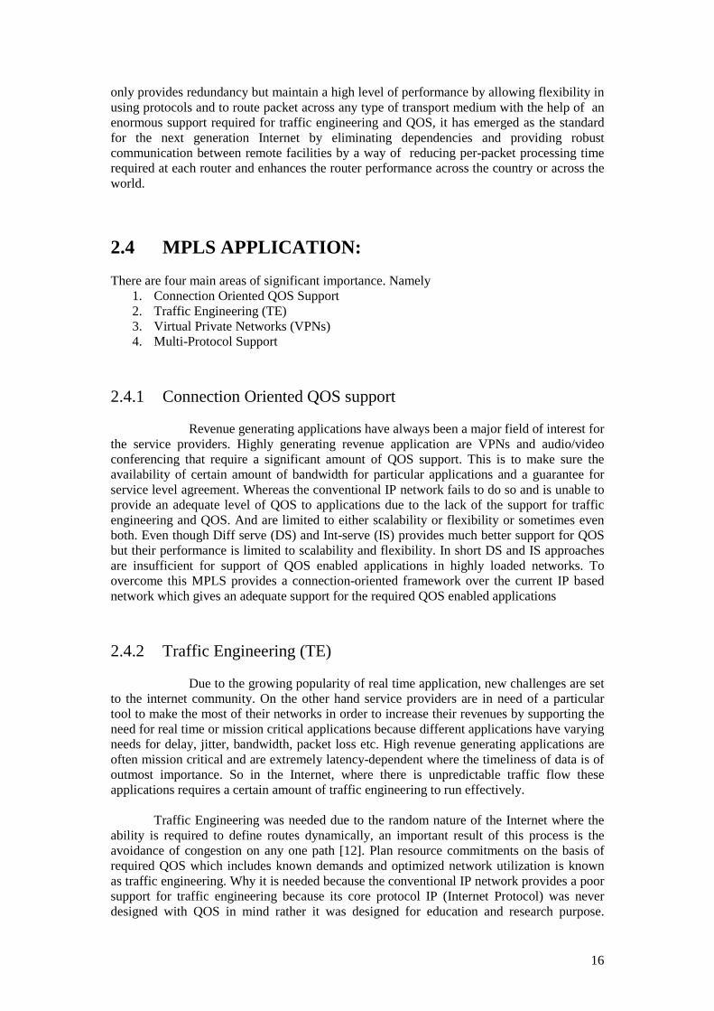
a packet within MPLS domain between ingress and egress nodes while passing through the intermediate LSRs is called Label Switched Path (LSP).
Figure 3: Label Switched Path in an MPLS enabled network
Switching is made possible by forwarding packets along virtual connections called label switched paths. These LSPs form a logical network on a regular physical network and guarantee connection-oriented processing over the connection less IP networks. Each MPLS packets has a header that consist of 4 fields, a 20-bit label value field, 3-bit for class of service field,1-bit label stack (bottom of stack flag).if set will indicate that the current label is the last label in the stack and the 8-bit time to live field (TTL). Entry and exit point with in an MPLS networks are called label edge router where as label switch routers are within an MPLS networks. They Examines only the MPLS header containing the label and forward the packet no matter what ever the underline protocol is. Each LER maintain a special database for destination address to label the packet when a packet enters MPLS network. The objective of adding label to incoming packet is to avoid a route lookup in forwarding the packet as it makes its way to egress router. Between two endpoints the flow of packet defined by the label which determines the Forward Equivalence Class (FEC).
A label distribution protocol (LDP) or RSVP can be needed by MPLS to distribute labels so that label switch path (LSP) can be setup. In a hop-by-hop LSP next interface is determined by the label switched Route (LSR) by looking at the layer-3 routing topology database and sends a label to request to the next hop. The Forward Equivalence Cass (FEC) is a type of class that represent a group of packets that share the same characteristics and have the same requirements for their transport and are provided with the same treatment and routes to the destination. The FEC of a packet can be determined by many parameters e.g. it can be determined by source or destination IP address, source or destination port number, diff serve code point and the IP protocol identity. Based on that FEC a table “Label Information Base (LIB)” is build by each LSR that specifies how a particular packet must be forwarded. The LIB comprised of FEC to label binding information. After determining a Forwarding Equivalence Class for a packet an appropriate label is attached to it from the LIB. Based on that label belonging to a particular FEC the packet is forwarded through

20
several LSRs along its way to its destination. As the packet traverses each LSR, the label is examined and replaced by another appropriate label and forward the packet to the next LSR that is close to the destination along the LSP.
Figure 4: Assignment of labels in an MPLS domain and IP forwarding [16]
LSP must be setup and the appropriate QOS parameters must be defined before assigning a packet to a FEC. Defining QOS parameters means setting aside a number of resources committed to a path and managing certain operation like queuing and discarding policies.
Data transmission in MPLS occurs on label switched path. Two protocols are used to
setup LSPs so that the necessary information can be passed among the LSRs. To determine a route from the ingress to the egress a routing protocol is required and the path along which the packet follows its way to its destination within MPLS domain is called the path. There is a special way through which labels can be distributed along the path. These LSPs can be controlled driven or it can be explicitly routed (ER-LSP).
2.7 Controlled Driven
That is they are established prior to data transmission or either data travel that is upon detection of certain flow of data. In hop-by-hop manner next interface is determined by each LSP by looking at layer-3 routing information provided by the routing protocol so that the label request can be send to the next hop. These labels are distributed using label distribution protocol or resource reservation protocol (RRP) or piggy backed on routing protocol like border getaway protocol (BGP) and open shorts path first (OSPF).Thus high speed switching of data is made possible only when data packet is encapsulated with the label during their journey from source to destination because of the fixed length label at the beginning of the packet can be used by hardware to switched packets quickly between links.

21
2.8 ER-LSP
In ER-LSP complete route is specified in setup message that contain a list of all the nodes being traversed in that LSP which can be controlled and specified by the network management applications. The most attractive feature of the ER-LSP is that the network traffic is independent of the underlying layer-3 topology which provides a greater feasibility in supporting traffic engineering (TE). Within an MPLS domain packets make their destination while following a LSP that are established according to the calculated routes. Service provider can set LSPs according to their specific needs in order to attain better performance and to avoid network congestion. To setup LSP a route discovery approach is used when defining a route from source to destination.
2.9 MPLS Network Architecture Components, operations, protocols stack architecture and applications
MPLS architecture is divided into 2 components
1. Forwarding Components 2. Control Components
2.9.1.1 Forwarding components
Forwarding component perform forwarding of data packets by fetching appropriate label from the database maintained by label switch based on the label carried by the packet.
2.9.1.2 Control Component
Control components are used for creating and maintaining label forwarding information between groups of interconnected label switch.
To optimizing the performance of operational networks and is helpful in the measurements and dynamic control of internet traffic by introducing a simple load balancing technique. Data transmission in MPLS occurs on label switched path. These LSPs can be controlled driven that is they are established prior to data transmission or either data travel that is upon detection of certain flow of data. These labels are distributed using label distribution protocol or resource reservation protocol (RRP) or piggy backed on routing protocol like border getaway protocol (BGP) and open shorts path first (OSPF).Thus high speed switching of data is made possible only when data packet is encapsulate with the label during their journey from source to destination because the fixed length label at the begging of the packet can be used by hard ware to switched packets quickly between links.
The two participating devices in the MPLS protocol mechanisms are Labels Switch
Routers (LSRs) and Label Edge Routers (LERs). A Label Switch Routers (LSR) is a high speed router in the core of MPLS networks that participate in the establishment of label switch path. That facilitates high speed switching of data packet using those established path.

22
There are two major planes in MPLS architecture
(a) Control plane (b) Data plane
2.9.1.3 Control plane:
Control plane perform information exchange between neighboring devices by the use of different protocol such as OSPF, IGRP, EIGRP, IS-IS, RIP and BGP. Labels are exchange in a control plane that requires the use of label exchange protocol TDP, LDP, BGP and RSVP.
2.9.1.4 Data plane:
Simply forward the packet based on labels, independent of type of routing protocol use or label exchange protocol. Label based packets are forwarded using a label lookup in label Forwarding Information Base (FIB) table, which is populated by TDP or LDP.
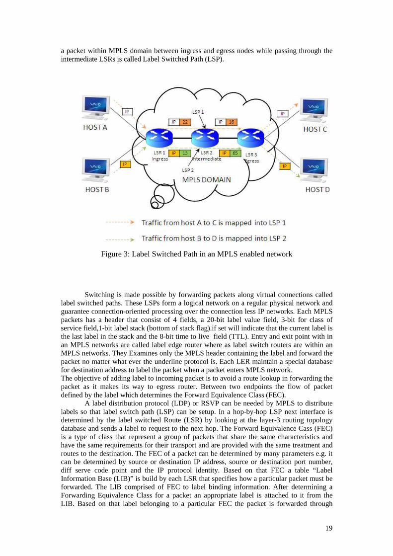
2.9.2 MPLS Node Basic Architecture Here in this session, the basic architecture of MPLS node that is responsible for performing IP forwarding will be explained. Every node in MPLS is an IP router on a control plane and there might be more than one protocol running on each node to exchange IP routing information between its peers within a network.
23
Figure 5Architecture of MPLS Node
The routers in MPLS network contain an IP routing table which is used to exchange the label binding information. That information is used by the adjacent MPLS peers for exchanging labels for individual subnets, which is found in the routing table. A specified LDP is used in label binding exchange for unicast destination based IP routing. In MPLS transmission takes place on the basis of labels attached to packets that direct it all the way towards the destination and that is done only when labels are exchanged with adjacent peers in order to form a Label Forwarding Table, a Label Forwarding Table is therefore acts as a database in forwarding packets within the MPLS network.
2.9.3 MPLS Header MPLS Header is created by ingress router and is 32 bit in length [11], [12]. That 32 bits Header field is embedded between layer-2 and layer-3 headers. Shim header encapsulates every incoming packet. They are shimmed because they are placed between the existing headers. As it is a small header so it is appropriate to call it shim. Figure shows MPLS header format.

24
Figure 6 MPLS Shim Header [11]
2.9.4 MPLS Label
A label is a short fixed length entity (header) [11] created by label edge router to forward packets. Label Edge Routers and Label Switch Routers then use these label to make forwarding decision. Labels contain values that indicate where and how to forward frame with specific value by looking into label forwarding information base (LFIB).
2.9.4.1 Label format of MPLS Table 1: MPLS Label Format [16]
0 1 2 3 0 1 2 3 4 5 6 7 8 9 0 1 2 3 4 5 6 7 8 9 01 2 3 4567 8 9 0 1
Label Exp S TTL
MPLS label contains following information 20 bit contain label 3 bit contain exp 1 bit contain in S and 8 bit contain in TTL
25
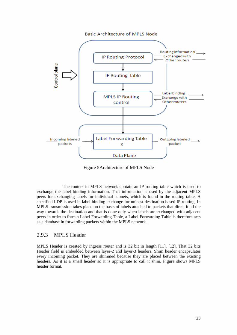
Table 2: MPLS Labels between Layer-2 and Layer-3 Headers
L2 Header Last Label …. First Label L3 Header
The shim header may contain more than one label. Labels act as path identifiers, at each router the contents of the labels are examined and the next hop is determined. The fixed length 20 bit space in the label is set aside for the address space having a local significance only. Labels are chosen locally and are advertised by a router to its neighbors using a Label Distribution Protocols and are swapped away of each incoming packet before being forwarded to the next routers. MPLS is a datagram oriented technology though it uses IP routing protocols. In MPLS label the EXP is a 3 bit field set aside for experimental use [10]. S bit is a 1 bit field that indicates the bottom and is set for the stacking of labels and finally TTL is an 8 bit field which determines the time and number of hops a packet has to traverse before it can die. Each label has a local significance and short identifier with fixed length, which is used to identify a particular FEC. When they reach at MPLS network at the ingress node, packets are divided into different FECs, on which different labels are encapsulated. Later forwarding of the packet is based on these labels.
2.9.5 LSRs and LERs
LERs devices are edge operators at the accessing network and MPLS networks and can support multiple ports connecting to dissimilar networks such as frame relay, ATM and Ethernet. At each incoming packet a label is inserted (pushed) at the edge router (Ingress). With the help of signaling protocol label switch paths are established which help in forwarding the traffic onto MPLS network. Label switch path is established using label signaling protocol. Label Switch Routers are the core routers in the MPLS domain and usually called core network routers [12]. As a packet enters in to MPLS network a label or labels are attached [14] and as those packets leaves the MPLS networks those label are removed by the edge routers.
2.9.6 FEC
A Forwarding Equivalence Class (FEC) is a type of class that represent a group of packets that share the same characteristics and have the same requirements for transport [12]. Packets having the same FEC are forwarded in the same manner on the same path and given the same treatment. In regular IP forwarding a router consider two packets to be in the same FEC, but in MPLS FEC is assigned to a packet only once by the label edge router as it enters the MPLS network. FEC for a particular packet is encoded within the label and attached to that packet before forwarding and form here on there will be no further analysis of the packet header as long as that packet is in the MPLS domain but the label is used to identify and index in the table in order to determine the next hop. At each hop the old label is removed and a new label in inserted to that packet and the packet is forwarded to the next hop.
2.9.7 LSP
LSP is a connection oriented technology because each path is setup on the basis of priority of the data flow. As the packet enters an MPLS domain through the ingress node labels are added and at each intermediate router the labels are added and the older label is

26
swapped away till it reaches the end of the network (egress node). The distance a label travel from the ingress to the egress is called the Label Switch Path (LSP). A LSP describe a unidirectional route for the particular FEC that include a set of LSRs that a packet must traverse in order to reach the destination. Connection is setup on the basis of the underlying topology and not on the requirement of the data flow i.e. LSP is created no matter there is any traffic waiting to go through the path of a particular FEC. Different LSR are used to return the traffic because of the unidirectional. In TE the LSR forward the packets locally with a new label based on the incoming label of the packet to a different interface. On the establishment of LFIB on all LSRs, each LSP is associated with a particular label, FEC and interface. In ATM same mechanism is used like in MPLS. At each LSR in coming labels are examined and swapped away with the new outgoing labels.
2.10 Label Distribution
In MPLS there are two protocols that are used for label distribution for MPLS, they are:
• Label Distribution Protocol (LDP) • Constraint-based Routing Protocol (CBR)
Apart from these two protocols there are extensions of the existing protocols that are also used for the distribution of labels within an MPLS domain; these are OSPF, BGP and RSVP. In MPLS path is calculated by LSRs through the use of control plane because there is special procedure adapted by each LSR for informing its peer LSRs about the binding of the label to a particular FEC. MPLS uses LDP for the distribution of labels between adjacent peers. MPLS applications also use other protocols MP-BGP and RSVP-TE for the distribution of the labels.
2.11 MPLS loop detection and prevention While deploying the MPLS architecture it is the capability of MPLS to detect and
prevent loop. Forwarding loop is a process through which forwarding of packets takes place down to incorrect path for that particular destination, forwarding is done based on the information available in the routing table. Such type of situation occurs when dynamic routing protocols are used during convergence transition or when the router is not configured properly, like at some stage the router is pointing to another node that is not actually the next hop for that destination. In MPLS architecture when we talk about control plane and data plane, loop prevention is implemented both in Frame mode and Cell mode.
2.11.1 Frame mode
In independent control mode labels are associated to particular FECs when running MPLS in Frame mode. In MPLS label assignment to a particular FEC is done on whether the FEC exists in the LSR’s routing table and in this way label switched path is established and MPLS can detect and prevent forwarding loops.
2.11.2 Data Plane mode
Data plane in MPLS network is used in the prevention of loops in such a way that it examine the TTL field of the incoming IP packet, at each router in MPLS domain decrement
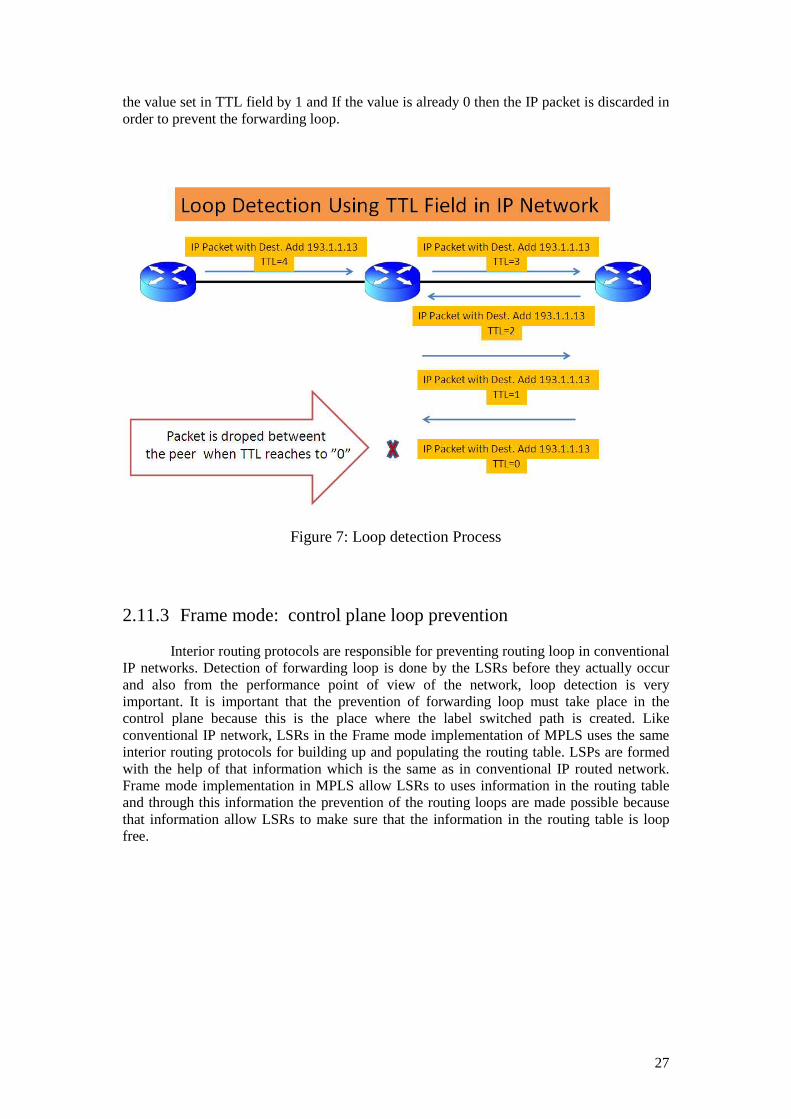
27
the value set in TTL field by 1 and If the value is already 0 then the IP packet is discarded in order to prevent the forwarding loop.
Figure 7: Loop detection Process
2.11.3 Frame mode: control plane loop prevention Interior routing protocols are responsible for preventing routing loop in conventional
IP networks. Detection of forwarding loop is done by the LSRs before they actually occur and also from the performance point of view of the network, loop detection is very important. It is important that the prevention of forwarding loop must take place in the control plane because this is the place where the label switched path is created. Like conventional IP network, LSRs in the Frame mode implementation of MPLS uses the same interior routing protocols for building up and populating the routing table. LSPs are formed with the help of that information which is the same as in conventional IP routed network. Frame mode implementation in MPLS allow LSRs to uses information in the routing table and through this information the prevention of the routing loops are made possible because that information allow LSRs to make sure that the information in the routing table is loop free.

28

29

30
3 CHAPTER 3
3.1 MPLS TRAFFIC ENGINEERING (MPLS-TE)
3.1.1 What is QOS?
Service refers to an overall treatment given to customer’s traffic within a particular domain. The provided service is worthwhile only if it meets the requirements of the end-user application. So the basic aim of the service is to maximize the satisfaction up to the optimal level so QOS is defined by the underlying requirements and SLA metrics like delay, jitter, packet loss, through put etc. of an application. QOS is not only to ensure SLA requirements for that application but also to ensure management of the available resources. To ensure maximum throughput the network must guarantee significant amount of capacity over the traffic load and in this way the metrics like delay, jitter and loss can be minimized. Another issue is created when we talk about QOS that is “cost”. That is ensuring a minimum amount of network resources that are sufficient for any level of traffic loads. Here engineering comes into consideration in order to minimize cost. QOS always means end-user satisfaction e.g. if we talk about voice over IP call quality, it should be at a level of quality that is acceptable that mean the SLA requirements are met. Class of Service (COS) and Type of Service (TOS) is often used with respect to QOS, whereas COS is a term used for the classification of the traffic over which a common action is applied and TOS refers to the type of service octet in IPv4 packet header.
3.1.2 Best-effort Service
In best-effort service traffic is delivered to the destination without any guarantee, the sender never knows that the data has been delivered. In best-effort the performance of the network is very good and the nodes that are used are inexpensive. No resources are pre allocated meaning that the traffic has to pass through the network under the current traffic load and there is no solution to inform the sender that the packet is lost in its way or corrupted. Within a network the delivery of the packet may be delayed because of a number of factors and also they can be received out of order at the destination. In short best-effort service is ill-suited for those applications that require significant amount of QOS. When we talk about QOS some factors like classification, scheduling, shaping and policing also come to consideration with respect to the underlying aspect conditions of the network. While having constraints upon aggregate bandwidth, paths are determined by TE on an aggregate base by TE and Diffserv mechanism which is used for scheduling on per-COS basis at each link. MPLS TE and Diffserv being orthogonal technologies can be used for common benefits with respect to QOS requirements. Like TE is helpful in distributing traffic through load balancing over other available links so that the network may not get overcrowded by distributing the traffic over underutilized link that may not be the shortest one in order to effectively use the network resources whereas Diffserv allow scheduling of packets on per-COS basis.

31
3.1.3 Link Congestion
One of the main issues in the IP networks is that the traffic follows the path which has the minimum numbers of hops while the remaining paths remain under utilized or not even utilized. As shown in the figure 9. In that diagram C-D-G is the shortest path with minimum number of hops. Only that path will be selected who has the minimum number of hops. In conventional routing all the packets are directed outwards to their destinations whose destination address share the same prefix and have the same subsequent hop. All the traffic will follow C-D-G path, even when C-E-F-G path is much better option to distribute the traffic uniformly across the network and to achieve performance and better resource utilization.
An IGP can be driven to make use of a path with additional hops by counting bandwidth, as one of the link metrics for SPF computation, but this is the irregular calculation where it has no perception of congestion. In view of the fact that all the packets are not formed equally i.e. they differ in length and size like packets shipping voice and video are poles apart from those packets carrying data. So following the conventional routing approach they may not be intelligent enough to reach their destination in the arrangement of time and order to meet the application need because voice and data ought to be given precedence over standard data packets, if not, they can get trapped behind normal data packets whose quality of service (QOS) necessities are not too high or sensitive. This is what makes conventional IP packet forwarding poorly suitable for current large scale revenue generating application such as VOIP and video conferencing. The answer to this problem is provided by Traffic Engineering (TE), which ensures bandwidth guarantee, explicitly routed Label Switched Path (LSP) and an efficient utilization of network resources.
MPLS architecture enables the constant incorporation of conventional routers and ATM switches in an integrated IP backbone.
The supremacy of MPLS nevertheless lies in other applications that were prepared to
be possible, ranging from traffic engineering to Virtual Private Networks (peer-to-peer). Application use control plane just like IP routing control plane to lay down the label switching database. The given diagram shows the interaction between these applications and the label-switching matrix.
Figure 8: MPLS Application and their Interaction
32
3.2 TRAFFIC ENGNEERING IN MPLS
In the preceding chapters we momentarily explain MPLS and its architecture with different state and examples. In this section our centre of attention will be traffic Engineering and its architecture.
Traffic Engineering (TE) is a distant and said to be clear as the undertaking of
mapping traffic flows onto an on hand physical topology. It is a dominant implementation that can be used by ISP to balance the traffic shipment and the various links in order to increase the network performance [12] and also allow it to work on a pretty large scale.
3.2.1 Introduction
In Convectional IP routing we can examine that it acts upon destination based routing but in MPLS we can examine that source base routing is performed. According to the up to date information if we look at the last few years most of ISPs take in to account conventional routing mechanism and yet they are not able to take full benefit of this type of the underlying deployed resources. What they do to overcome their setback by cleanly adding bandwidth and link capacity but what about the congestion issue? The reasons of congestion are not simply due to shortage of bandwidth. Through Multi Protocol Label Switching-Traffic engineering (MPLS-TE) comes the uprising and finest solution which leads to the progress and advancement in the ground of data networks.
3.2.2 Traffic Engineering TE involves computation, calculation and configuration of paths throughout a
network so that the bandwidth can be used efficiently. TE is promising that act as a key tool for achievement and accomplishment of goals like fast, absolute utilization of bandwidth, dependable, cost valuable, mechanized and differentiated services.
TE on the whole deals with the matter of performance and concern with the
optimization of operational IP networks. Since TE comes in a much broader-spectrum with respect to QOS in the logic that it usually maximizes operational network efficiency. It has the capability of placing traffic onto the network where the links are underutilized and while taking into consideration of QOS issue traffic is distributed where needed that’s how the network congestion is minimized.
In circuit- switched networks, TE is automatically done by the use of offline tools. The outcome is copied to the switches and hence the availability of deterministic paths for different destinations is made possible. In conventional IP networks, there are many scenarios where traffic can be engineered.
3.2.3 Link Congestion
A fighting fit recognized issue in IP networks is the calculation of IGP best paths which results in over utilization of those specific paths while alternate paths are either underutilized or not utilized at all [10].
33
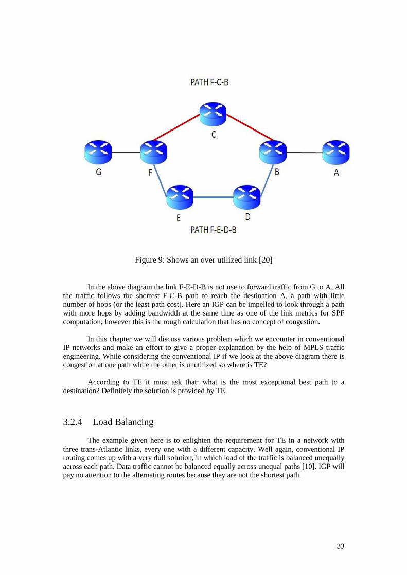
Figure 9: Shows an over utilized link [20]
In the above diagram the link F-E-D-B is not use to forward traffic from G to A. All the traffic follows the shortest F-C-B path to reach the destination A, a path with little number of hops (or the least path cost). Here an IGP can be impelled to look through a path with more hops by adding bandwidth at the same time as one of the link metrics for SPF computation; however this is the rough calculation that has no concept of congestion.
In this chapter we will discuss various problem which we encounter in conventional
IP networks and make an effort to give a proper explanation by the help of MPLS traffic engineering. While considering the conventional IP if we look at the above diagram there is congestion at one path while the other is unutilized so where is TE?
According to TE it must ask that: what is the most exceptional best path to a destination? Definitely the solution is provided by TE.
3.2.4 Load Balancing
The example given here is to enlighten the requirement for TE in a network with three trans-Atlantic links, every one with a different capacity. Well again, conventional IP routing comes up with a very dull solution, in which load of the traffic is balanced unequally across each path. Data traffic cannot be balanced equally across unequal paths [10]. IGP will pay no attention to the alternating routes because they are not the shortest path.

34
Figure 10: Shortest Path Computation [20]
In this diagram data between A and E can be uniformly load balanced transversely, from top and bottom paths, but this does not catch the dissimilar link sizes between {B-D (10, 60) Mbps} and between {C-D (10, 40) Mbps}. The {10, 60} details of the links at the top of diagram representing two paths, the first (A-B) has a link of 10 Mbps and the second (B-D) has a bandwidth of 60 Mbps.
3.2.5 Link protection
If there is a problem in a link down at the primary LSP i.e. if there is a path or device failure, the implemented routing protocols have to come back again for the full SPF calculation in order to forward the traffic again [10]. This process is time consuming and

35
may take several seconds.
Figure 11: Primary Path Failures [20]
Routing protocols must reunite if there is any problem in the link before traffic from A to B can cross C. The above figure illustrates a situation when there is a failure on a most important link. MPLS TE allows network operators a means to resolve the troubles described in first diagram through this scenario. The solution to this is that the TE involves constructing an LSP (tunnel) throughout the MPLS core. Any packet that enters at the start of the tunnel (called the head end) will constantly be following the same path before popping out the other end. Unlike in conventional IP, strict source routing is done which can also support a determined path through the network, TE allow bandwidth reservation for each tunnel at each LSR. MPLS TE dynamically establishes and maintains LSP throughout the MPLS networks. There are two protocols used for distributing label within the MPLS domain, within the contest of traffic engineering, one is Constraint-based routing and the other is resource reservation protocols.
3.3 Benefits of MPLS-TE TE provides systematic, logical, technical measurements, classification, modeling, and
management of Internet traffic. MPLS provides the groundwork that allows traffic engineering in an ISP networks due to the following reasons.
1. Maintain support for the specific paths and allows network to identify the
precisely exact path that an LSP takes across the ISP’s network.
2. Individual LSP statistics used to recognize bottlenecks and trunk utilization.
3. Constraint Base Routing (CBR) provides capabilities that allow LSP to gather
and meet definite performance requirements before their establishment.

36
4. Solutions provided by MPLS are not limited to ATM infrastructures but they
can easily be run on packet oriented networks.
5. TE allows ISP to balance their hardware and resources, like router and
switches in the network so that there is a proper employment of all the
components.
6. TE also ensures that none of the component is over utilized or underutilized.
7. TE makes effective use of the available bandwidth so to achieve best
performance even in the situation of congestion.
3.4 MPLS-TE Working
In MPLS Traffic Engineering there is an automated way of establishing and maintaining of the tunnels across the backbone, with the help of RSVP. The usage of the tunnel at any point in time is determined on the basis of the required resources for that tunnel and also keeping in mind the network resources, such as bandwidth. IGP is responsible for routing the traffic automatically into tunnels [10]. Only a single tunnel connects the ingress node to an egress node when a packet travels through the backbone in MPLS network.
MPLS TE development mechanism
• RSVP with TE extension signalled the LSP tunnels that are unidirectional.
• Link state IGP with extension for the global flooding of resources and
automatic routing of traffic into LSP tunnels.
• MPLS-TE path calculation module determines the path to use for LSP
tunnels.
• An MPLS-TE link management module is responsible for link admission and
bookkeeping of the resource information that is to be flooded.
• Routers with data link layer capability in a Label switching provide the
ability to direct traffic across several multiple hops which is intended by the
resource-based routing algorithms.
IGP operates an Ingress node at the beginning of the network in order to find the type of traffic that should go to a particular Egress device. MPLS-TE path computation and signaling modules determines for each tunnel about the number of packets and bytes sent because MPLS-TE is established dynamically. There are two protocols used for distributing label within the MPLS domain, within the contest of traffic engineering, one is Constraint-based routing and the other is resource reservation protocols. Depending on the type and amount of data flow, it is sometimes not possible for the entire flow to fit in a particular link so for this reason multiple tunnels are configured to share the load.
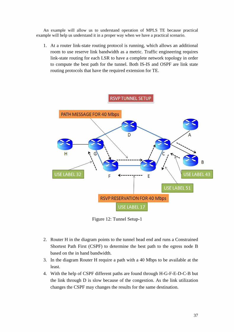
37
An example will allow us to understand operation of MPLS TE because practical example will help us understand it in a proper way when we have a practical scenario.
1. At a router link-state routing protocol is running, which allows an additional
room to use reserve link bandwidth as a metric. Traffic engineering requires link-state routing for each LSR to have a complete network topology in order to compute the best path for the tunnel. Both IS-IS and OSPF are link state routing protocols that have the required extension for TE.
Figure 12: Tunnel Setup-1
2. Router H in the diagram points to the tunnel head end and runs a Constrained
Shortest Path First (CSPF) to determine the best path to the egress node B
based on the in hand bandwidth.
3. In the diagram Router H require a path with a 40 Mbps to be available at the
least.
4. With the help of CSPF different paths are found through H-G-F-E-D-C-B but
the link through D is slow because of the congestion. As the link utilization
changes the CSPF may changes the results for the same destination.
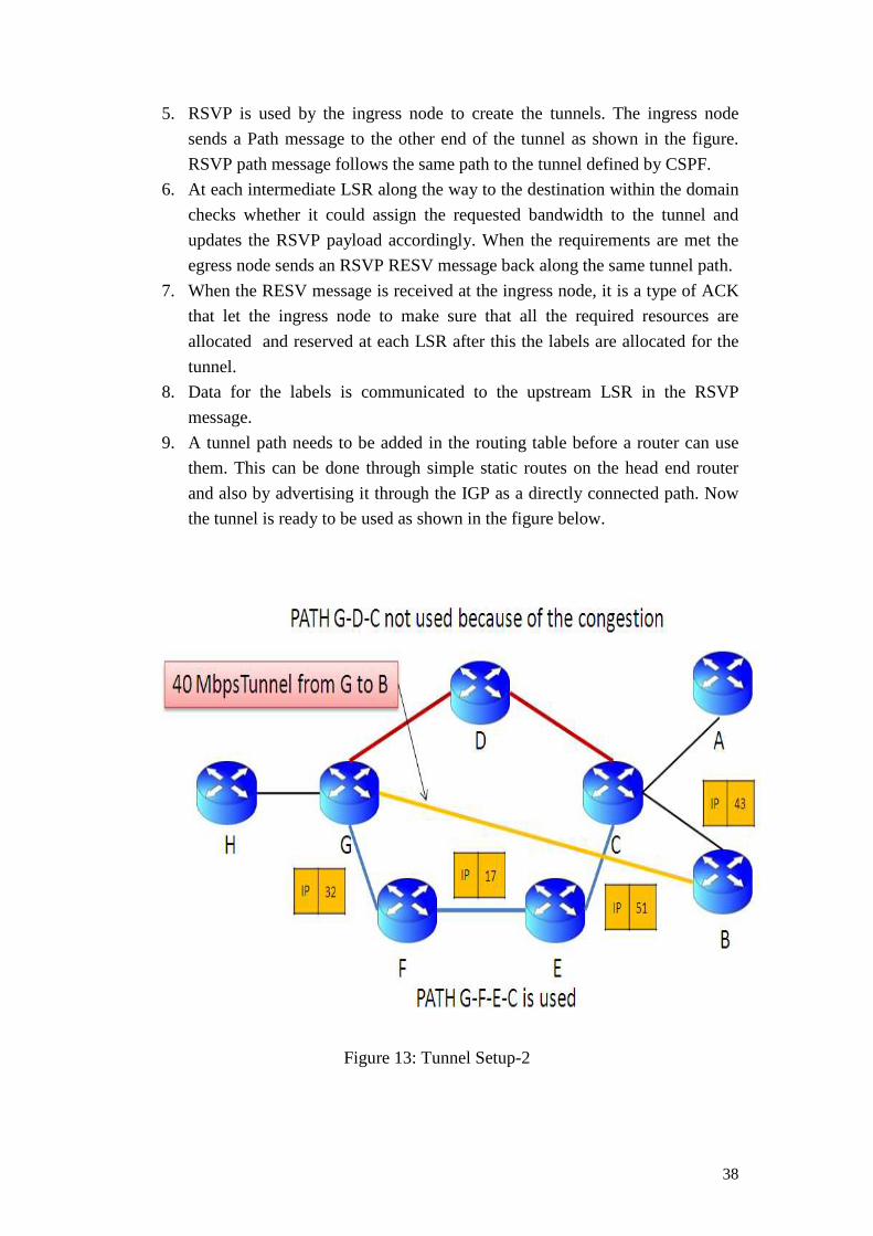
38
5. RSVP is used by the ingress node to create the tunnels. The ingress node
sends a Path message to the other end of the tunnel as shown in the figure.
RSVP path message follows the same path to the tunnel defined by CSPF.
6. At each intermediate LSR along the way to the destination within the domain
checks whether it could assign the requested bandwidth to the tunnel and
updates the RSVP payload accordingly. When the requirements are met the
egress node sends an RSVP RESV message back along the same tunnel path.
7. When the RESV message is received at the ingress node, it is a type of ACK
that let the ingress node to make sure that all the required resources are
allocated and reserved at each LSR after this the labels are allocated for the
tunnel.
8. Data for the labels is communicated to the upstream LSR in the RSVP
message.
9. A tunnel path needs to be added in the routing table before a router can use
them. This can be done through simple static routes on the head end router
and also by advertising it through the IGP as a directly connected path. Now
the tunnel is ready to be used as shown in the figure below.
Figure 13: Tunnel Setup-2

39
This is the basic operation of MPLS Traffic Engineering. Now we are going to take another model of it and study that how make MPLS traffic engineering is good and effective in use by using the current bandwidth as shown in the following diagram. Figure shows that how TE uses LSPs to solve the problem.
Figure 14: TE in MPLS Domain [20]
In the figure above there are three LSRs namely, LSR 1, LSR 2 and LSR 3 while host A and host B are the source where as host C and host D are sink nodes and we also assume that the routers are connected through a 100 Mbps PVC connection. Here in this network we have communicating peers like host “A” is the source and host “C” is the sink and similarly host “B” is the source and host “D” is the sink. We assume that the traffic from both the hosts to their respective sink demands 100 Mbps. With the help of routing capability in MPLS, the traffic from host A to host C traverses through the LSP2 (LSR 1- LSR 2- LSR 3) whereas the traffic from host B to host D travel through LSP 1 (LSR 1- LSR 3).
As it is quite clear from the above example that traffic is uniformly distributed between multiple routes but because of MPLS, traffic routing capability, the traffic can be routed across the network according to its demands, like bandwidth guarantees, by just establishing different LSPs in order to attain efficient resource utilization and guarantee for bandwidth, and achieving high level of network performance. Management and Limitation of Traffic Engineering (TE)
In this chapter as we have describe the basic function and its benefits of Traffic Engineering in an autonomous system in the Internet. Now the limitation in IGP when compared with traffic and resource management is highlighted. The main objective of TE is
40
to ease the reliability and efficiency and to increase the dependability of an operating network while maintaining and optimizing network resource utilization along with traffic performance concurrently. Performance Objectives for TE
Performance of traffic engineering can be classified into two categories. Following are the main features associated with TE.
1. Traffic Oriented. 2. Resource Oriented.
3.4.1 Traffic Oriented
In “traffic oriented traffic engineering” the QOS of Traffic streams are enhanced. The key traffic oriented performance Objectives for a single class in the best effort Internet service model include: Bringing the loss ratio of packets and delay to a minimum level and maximizing the throughput. The most important factor for a single class that should be considered in Traffic oriented engineering is the minimization of packet loss ratio.
3.4.2 Resource oriented
In “resource oriented traffic engineering” the optimization of resource utilization is taken into consideration. As the problem face in conventional IP routing that a particular subset of a network is fully utilized while the other is totally underutilized, so resource oriented traffic engineering is there to make sure that the particular subset of the network is not over utilized while the other subset remain underutilized.
Traffic Engineering’s main objective is to efficiently manage bandwidth resource. In a network congestion causes problems and a significant delay unlike transient congestion that result from instantaneous traffic bursts.
Such type of congestion typically comes under two scenarios. 1. Network resources are insufficient or the network is unable to accommodate
offer load. 2. Traffic streams are bound to follow those path that are inefficient and lack in
resources which results in an over utilization of that subsets while others remain underutilized.
There are a number of different solutions to overcome the first kind of congestion, they can be addressed by
• Capacity expansion.
• Application used for classical congestion control techniques.
• Both, Classical congestion control techniques effort to adjust the
requirements so that the resources become available for that particular traffic
41
Congestion control for traffic engineering comes with some very good techniques like limiting data rate, window flow control, queue management in routers and Schedule-based control. Secondly the congestion problems that results from inefficient resource allocation can easily be overcome through TE by adopting load balancing policies. The advantage of this policy is to minimize congestion which results in maximizing the resource utilization through proper resource allocation. Due to efficient resource allocation the congestion in a network is minimized and decreases packet loss ratio and transit delay while the aggregate throughput increases.
3.5 Traffic and Resource Control
To increase the performance of an operational network is fundamentally a control issue. In the TE process model a suitable mechanization acts as the watchdog in an adaptive feedback control system. The system includes an interconnected network element, system for monitoring the performance and a set of tools for the network management configuration. The traffic engineer is responsible for formulating the control policy and observes network with the help of monitoring system.
The flow of traffic is characterized according to their requirements and control operations are applied in order to drive the network to achieve a desired state with respect to the control policy. This can be achieved by taking action according to the underlying state of the network or by forecasting techniques to anticipate future trends and take necessary measure for applying action to mitigate undesirable future states. Following control actions must be provoked,
1. Alteration in the traffic management parameters. 2. Alteration in the parameters those are associated with routing. 3. Alteration in the attributes and constraints related with resources.
The level of manual involvement in the TE process must be reduced and should take place only when required. With the help of automated control actions this can be done exactly as needed.
3.6 Limitations of Current IGP Control Mechanism in accordance with TE
The existing capabilities for control mechanism offered by the Internet interior gateway
protocols (IGP) are inadequate for TE. Here the complication arises to actualize the effective policies that address network’s performance problems. IGP based on shortest path algorithms which results in the over utilization of that link and in infect causes congestion in autonomous systems in internet. In SPF algorithms network resources are usually optimized based on a single metric. Since they are topology driven, so bandwidth availability and traffic shaping are not considered while taking routing decisions.
The major causes of congestion are 1. For the shortest path computation in multiple traffic streams unites a specific
links or router interfaces.

42
2. A given traffic stream is bounded to route over a link or router interface which lacks in the bandwidth resources to accommodate it.
The upper discussion explains the reasons for congestion even when sufficient alternating paths with excess capacity are available.

43

44
4 CHAPTER NO 4
4.1 LABEL DISTRIBUTON PROTOCOL
The Label Distribution Protocol (LDP) [8] as the name indicates that it is a protocol which is used to distribute label between LSRs. MPLS architecture does not follow a single method for signaling of label distribution. There is a set of procedures and methods for creating labels [12] through which LSPs are established by mapping layer-3 information into layer-2 switched path.
• Topology-based method • Request-based method • Traffic-base method.
A label distribution protocol is a protocol defined by the IETF in [13], which allow two LSRs to exchange information about how to map the incoming label. The mapping information is required in order to make forwarding decisions. When the label reaches at one of the intermediate LSR it uses that information stored in the table and forward the packet to the adjacent LSR, also known as its peer. LDP operates between directly connected LSRs via link or between non adjacent LSRs. LSRs that establish session and exchange labels and mapping information with the help of LDP are called Peer LSRs. When assignment of a label is done the LSR needs to let other LSRs know of this label with the help of LDP. IETF has defined LDP as a protocol that is used for explicit signaling and management of label space. They are also responsible for advertisement and withdrawal of labels. LDP uses Protocol Data Units (PDUs) to exchange messages between LDP capable LSRs. The header in the PDU indicates the length which is followed by one or more messages, intended for the partner LSR.
Figure 15: Logical exchange of messages in LDP [17]
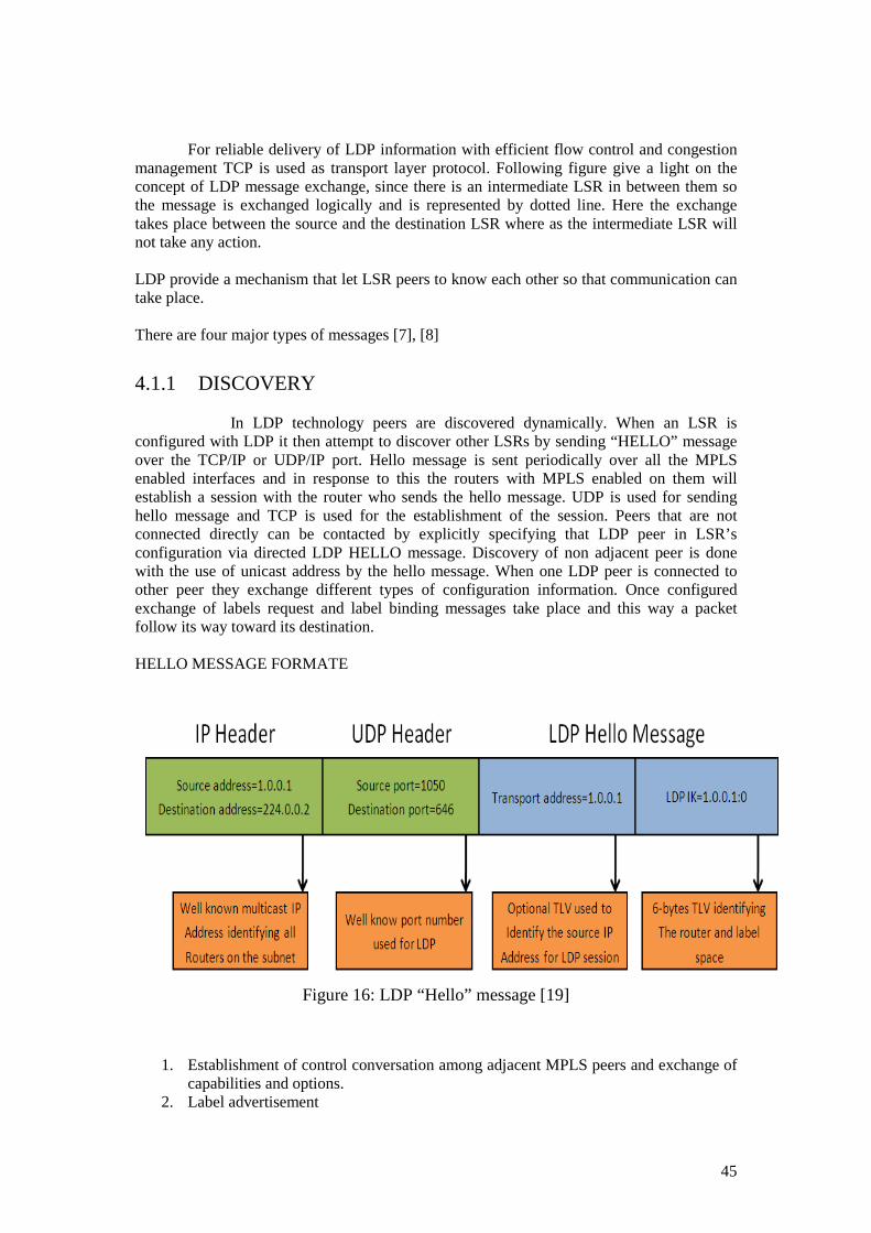
45
For reliable delivery of LDP information with efficient flow control and congestion management TCP is used as transport layer protocol. Following figure give a light on the concept of LDP message exchange, since there is an intermediate LSR in between them so the message is exchanged logically and is represented by dotted line. Here the exchange takes place between the source and the destination LSR where as the intermediate LSR will not take any action. LDP provide a mechanism that let LSR peers to know each other so that communication can take place. There are four major types of messages [7], [8]
4.1.1 DISCOVERY
In LDP technology peers are discovered dynamically. When an LSR is configured with LDP it then attempt to discover other LSRs by sending “HELLO” message over the TCP/IP or UDP/IP port. Hello message is sent periodically over all the MPLS enabled interfaces and in response to this the routers with MPLS enabled on them will establish a session with the router who sends the hello message. UDP is used for sending hello message and TCP is used for the establishment of the session. Peers that are not connected directly can be contacted by explicitly specifying that LDP peer in LSR’s configuration via directed LDP HELLO message. Discovery of non adjacent peer is done with the use of unicast address by the hello message. When one LDP peer is connected to other peer they exchange different types of configuration information. Once configured exchange of labels request and label binding messages take place and this way a packet follow its way toward its destination. HELLO MESSAGE FORMATE
Figure 16: LDP “Hello” message [19]
1. Establishment of control conversation among adjacent MPLS peers and exchange of capabilities and options.
2. Label advertisement

46
3. Destroying or withdrawal of labels.
4.2 Label Merging Label merging is a type of capability that allows forwarding of different packets having different labels, but belonging to same FEC [2], with the same single outgoing label. Merging mean, combining different labels those belongs to same FEC, with a same label. Within an MPLS domain an LSR is capable of merging different labels if there are two packets with separate labels by sending both the packets out with the same label though the same interface. Once the packets are sent with the same label, the information that they are received from different interface and with different labels are lost.
4.3 Label Retention There are two methods are defined for the treatment of label binding that are not the next hop for that FEC.
4.3.1 Conservative
4.3.2 Liberal
• In “conservative” mode [12] the binding of label and FEC received from LSR in the LIB that are not the downstream (next hop) of a given FEC are discarded. In this mood only few labels are required to be maintained by an LSR [4].
• In “liberal” mode [12] the binding of label and FEC received from LSR in
the LIB that are not the downstream (next hop) of a given FEC are maintained. Benefits of this mode include quicker adoption to topology change and traffic switching to other LSPs in case of changes [MPLS-1.PDF] [4].
4.4 Label Distribution Control Mode
MPLS define two different types of mode for the distribution of labels to the neighboring LSRs.
4.4.1 Independent
4.4.2 Ordered
• In “independent” mode [12] the LSR bind a label to an FEC independently from distributing the binding to other LSRs.

47
• In “ordered” mode [12] the LSR bind a label to an FEC if and only if the binding for the FEC is received for the downstream (next hop) LSR.
4.5 Label Binding and Assignment Label switching control is responsible for label binding and assignment. Labels binding process can be done locally or remotely. In control components, there exist two types of label binding. The first type of binding take place locally when the router chose a label and assign it and the second type of binding occurs remotely when the router gets some label binding information from other LSR which is created by that other router. Forwarding table is populated with the incoming and outgoing labels by the label switching control component. In the binding process a label is associated with a FEC that can be control driven or data driven. Labels that are going to receive the same treatment are bonded with a particular FEC. Labels are bonded to a FEC in response to a particular event which require such type of binding [12]. In control driven binding, labels and FEC information between identical peers are exchanged with the help of control messages. On the other hand when packets are received an analysis is made and on the basis of that analysis data driven binding takes place dynamically. More precisely binding can be classified as downstream or upstream binding. In downstream binding, labels that are bounded locally are used as incoming labels and the labels that are bounded remotely are used as outgoing labels whereas the second one is entirely opposite i.e. labels that are bounded locally are used as outgoing labels and the labels that are bounded remotely are used as incoming labels, the major difference between both bindings is that in local binding the label is chosen locally to associate with the binding by the LSR itself whereas in remote binding the label is chosen by other LSR [11].
In a downstream binding process the upstream router sends a packet to downstream router which is examined to find out the FEC to which the label belongs to i.e. the downstream router examine the incoming packet and found that the incoming packet is associated with a FEC label L. Furthermore the downstream router sends a request to upstream router to attach that particular label with all the next incoming packets that are intended for that particular FEC so that they should be treated in the similar manner. The downstream binding is classified into two categories.
4.5.1 Unsolicited downstream label binding
4.5.2 Downstream on demand label binding
• In an unsolicited downstream label binding the label association take place locally i.e. the downstream LSR associates locally a label for binding it with a particular FEC and advertises this binding information of that label for that FEC automatically to its neighbouring peers. Since the downstream router advertisers the binding information so there is no need for any type of request from other routers, the binding information will be known to other routers.
• On the other hand in downstream on demand label binding is done on a request that is being made explicitly. On a request by an upstream LSR the downstream LSR distributes a label for binding that label for a FEC.
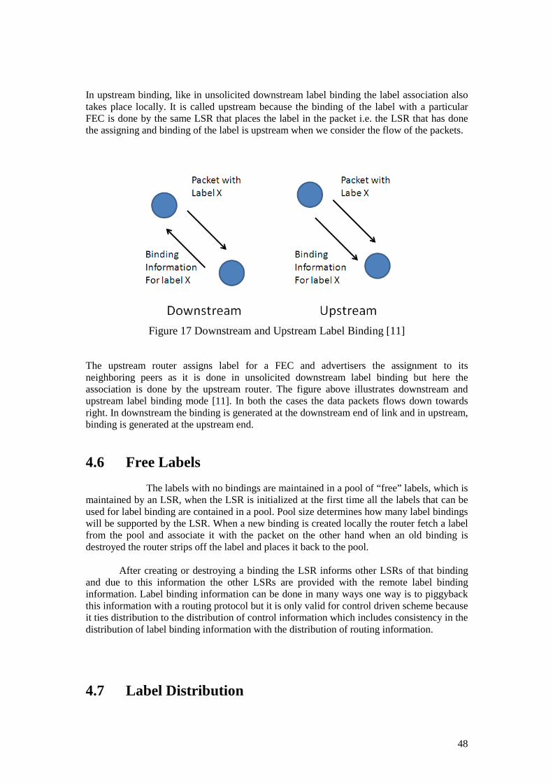
48
In upstream binding, like in unsolicited downstream label binding the label association also takes place locally. It is called upstream because the binding of the label with a particular FEC is done by the same LSR that places the label in the packet i.e. the LSR that has done the assigning and binding of the label is upstream when we consider the flow of the packets.
Figure 17 Downstream and Upstream Label Binding [11]
The upstream router assigns label for a FEC and advertisers the assignment to its neighboring peers as it is done in unsolicited downstream label binding but here the association is done by the upstream router. The figure above illustrates downstream and upstream label binding mode [11]. In both the cases the data packets flows down towards right. In downstream the binding is generated at the downstream end of link and in upstream, binding is generated at the upstream end.
4.6 Free Labels The labels with no bindings are maintained in a pool of “free” labels, which is maintained by an LSR, when the LSR is initialized at the first time all the labels that can be used for label binding are contained in a pool. Pool size determines how many label bindings will be supported by the LSR. When a new binding is created locally the router fetch a label from the pool and associate it with the packet on the other hand when an old binding is destroyed the router strips off the label and places it back to the pool.
After creating or destroying a binding the LSR informs other LSRs of that binding and due to this information the other LSRs are provided with the remote label binding information. Label binding information can be done in many ways one way is to piggyback this information with a routing protocol but it is only valid for control driven scheme because it ties distribution to the distribution of control information which includes consistency in the distribution of label binding information with the distribution of routing information.
4.7 Label Distribution

49
In MPLS there is a set of procedures that is used by LSRs to exchange label information in forwarding the traffic. A number of methods are available for distributing label in MPLS network. The most popular method among other is Label Distribution Protocol (LDP), Border Gateway Protocol (BGP) and Resource Reservation Protocol (RSVP). Whereas the most popular among those is the Label Distribution Protocol because of its popularity and support for traffic engineering and since then it has become the standard for label distribution in MPLS networks by IETF. To setup explicitly routed LSPs, a derivation from the LDP is “Constraint based Routing (CD-LDP)” used by the network managers in the management of sensitive traffic.
4.8 Label Spaces It is a way in which a particular label is associated with the LSR. LSR is responsible for establishing only one LDP session for each label space. There are two categories of label spaces.
4.8.1 Per platform label space
4.8.2 Per interface label space
• In per platform label space [9] the label allocation is done from a common pool having a unique value across the complete LSR. One LDP session is required by the per platform label space no matter the pair of LSRs have multiple parallel links between them.
• In per interface label space [9] a label range is specified with interfaces and multiple
label pools are defined from interfaces. Label that are provided on those interfaces are allocated from different pools. Unlike per platform label space the label value at different interfaces could be the same. Two octets in the header of LDP carry the interface label spacing identifier.
4.9 Label Merging In MPLS, assignment of FEC to a particular packet is done at the entry point only once. The LSRs in MPLS network uses only the label and the COS field in order to make forwarding and classification decisions. So in that case label merging is possible only when multiple labels are going to receive the same FEC [12]. But in some cases label merging can be defined as an effort to share resources by the replacement of multiple labels that belongs to a particular FEC with a single outgoing label.
4.10 Label Stacking
Label stacking is one of the most powerful features of MPLS that is designed for the large networks. In MPLS network a packet may contain many labels that are organized in a LIFO (last in first out) stack. A label stack is build simply when an additional shim header is added to data packets. The top-most label is the one that is currently used to forward the packet and the last label in the stack has its stack bit set that indicates that it is the last label in the stack. When a packet reaches any of the LSRs in the MPLS domain, label can be

50
added in the stack called “push” operation or the label can be removed from the stack which is called as “pop” operation. Stacking of label allows the aggregation of LSPs into a single LSP for that part of the route between different domains.
Figure 18: Push and pop, old labels are removed and new labels are inserted at each
intermediate LSR.
4.11 LDP Header Each LDP message made up of header that indicates the length of the PDU. The header of LDP PDU may be followed by one or more messages send from one peer to the other within the MPLS network. The header within the message indicates the length after which the contents of the message will be followed. Type-Length-Field (TLV) scheme is used by LDP for encoding contents in the message. TLV has made UDP highly extensible by packaging them in PDUs and increased the backwards compatibility.
4.11.1 Protocol Structure, LDP Label Distribution Protocol.
Table 3: Label Distribution Protocol (Protocol -structure)
2 bytes 2bytes
Version PDU Length
LDP ID (6 bytes)
LDP Message

51
• Version – Version fields tells the version number of LDP. At present the number is 1.
• PDU Length – PDU length field tells the total length of the PDU excluding the version and the PDU length field.
• LDP ID – LDP ID identifies the label space of the sending LSR for which this PDU applies. The first 4 octets are used for the encoding of the IP address assigned to the LSR. The last 2 indicate label space in the LSR [13].
4.11.2 LDP messages format
Table 4: LDP message format
U Message type Message Length
Message ID
Parameters
• U -The U field indicates an unknown message bit. If set to 1 will be discarded by the
receiver silently.
• Message type – this field determine the type of message.
Message types that exist are: Notification, Hello, Initialization, Keep Alive,
initialization message, advertisement message, Address, Address Withdraw,
notification message, Label Request, Label Withdraw, Label Release, label mapping
message and Unknown Message name.
• Message length -- The length field indicate the length of the message ID in octets, It
also determine the mandatory parameters and optional parameters
• Message ID -- Message identification of 32-bit. Message ID is unique.
• Parameters -- The parameters field contain the TLVs. This field also tells about the
mandatory and optional parameters of the message [13].

52
4.11.3 TLV format
Table 5: LDP TLV Format
U F Type Length
Value
TLV Format
• U -- The first field represents the U bit which is an unknown TLV bit.
• F -- The “F” field forward unknown TLV bit.
• Type -- Encodes how the Value field is to be interpreted.
• Length – the length field indicates the length of the Value field in octets.
• Value – Value field encodes information that is to be interpreted as mentioned in the
Type field [13].
4.12 LDP Messages
Hellos message is a discovery mechanism used during the discovery of the other LSRs in MPLS domain. Each LSR keep records of all the hello messages that are received from other LSR peers. Hello message is sent periodically over all the MPLS enabled interfaces and in response to this the routers with MPLS enabled on them will establish a session with the router who sends the hello message. UDP is used for sending hello message and TCP is used for the establishment of the session. Peers that are not connected directly can be contacted by explicitly specifying that LDP peer in LSR’s configuration via directed LDP HELLO message. Discovery of non adjacent peer is done by the use of unicast address by the hello message. LSR uses UDP port to multicast hello message to all directly connected routers in the subnet.
4.12.1 Initialization message Initialization message is used in establishing and maintaining a session between the MPLS peers. When one LDP peer is connected to other peer they exchange different types of configuration information. Once configured, exchange of labels request and label binding messages take place, now the packet knows how to follow its way toward its destination. The configuration information that is exchanged is PDU size, time that a packet can stay alive, detection of loop, label advertisement discipline and path vector limit. Initialization message is send by the session requesting peer by using the TCP port.
4.12.2 Advertisement message Advertisement message is used by an LSR for the advertisement of the label to other peer LSR and it is also used for creating, deleting and mapping for the FECs.
53
Advertisement message is send by an LSR to its peers using the TCP port, it can also be used to request mapping of labels.
4.12.3 Notification message It is quite clear from its name that this message is some sort of notification from one LSR to the other. Notification message is a notice from one LSR to its peer about some abnormal or unusual error conditions i.e. a notification is send to the LSR when receiving unknown message, keep alive time expired, session termination occurred unexpectedly or shutdown by node. When an LSR receives such a message with the status code from its peer the first thing it does is to terminate the LDP session and this is done by closing the TCP connection. Once the session is terminated the LSR discarded all the state of association information with that peer LSR.
4.12.4 Keep alive message Integrity of the TCP connection between the peers is monitor with the help of keep-alive message. It is a thing to know that the other LSR is still alive that is there is still a connection between them.
4.12.5 Address message Address message is used by an LSR to advertise its interface address to its peer LSR. Once the address message containing interface address is received by the peer LSR, it updates the Label Information Base (LIB) for mapping and next hop address.
4.12.6 Label mapping message Label mapping message is used to advertise FEC label binding information between connected peers. A label request message consists of IP address and their associated labels.
4.12.7 Label request message In label request message the LSR request its peer for label binding to a particular FEC. The upstream peer send label request to downstream peer and recognize a new FEC through the forwarding table.
4.12.8 Label abort request message Label abort request message is used to aborts the outstanding label request when OSPF or BGP prefix advertisements to change the label request operation.
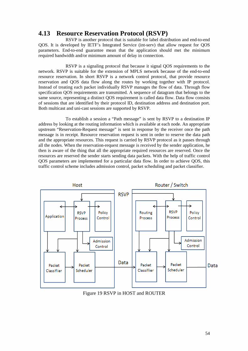
54
4.13 Resource Reservation Protocol (RSVP) RSVP is another protocol that is suitable for label distribution and end-to-end QOS. It is developed by IETF’s Integrated Service (int-serv) that allow request for QOS parameters. End-to-end guarantee mean that the application should met the minimum required bandwidth and/or minimum amount of delay in connection. RSVP is a signaling protocol that because it signal QOS requirements to the network. RSVP is suitable for the extension of MPLS network because of the end-to-end resource reservation. In short RSVP is a network control protocol, that provide resource reservation and QOS data flow along the routes by working together with IP protocol. Instead of treating each packet individually RSVP manages the flow of data. Through flow specification QOS requirements are transmitted. A sequence of datagram that belongs to the same source, representing a distinct QOS requirement is called data flow. Data flow consists of sessions that are identified by their protocol ID, destination address and destination port. Both multicast and uni-cast sessions are supported by RSVP. To establish a session a “Path message” is sent by RSVP to a destination IP address by looking at the routing information which is available at each node. An appropriate upstream “Reservation-Request message” is sent in response by the receiver once the path message is in receipt. Resource reservation request is sent in order to reserve the data path and the appropriate resources. This request is carried by RSVP protocol as it passes through all the nodes. When the reservation-request message is received by the sender application, he then is aware of the thing that all the appropriate required resources are reserved. Once the resources are reserved the sender starts sending data packets. With the help of traffic control QOS parameters are implemented for a particular data flow. In order to achieve QOS, this traffic control scheme includes admission control, packet scheduling and packet classifier.
Figure 19 RSVP in HOST and ROUTER
55
Each of them has their work to do to guarantee QOS because the packet scheduler is responsible for resource allocation required for the transmission of that data flow on the data link layer issued by each interface. While on the other hand the decision is done locally at each node which is called admission control mechanism in order to know whether the QOS support can be met or not. An upstream reservation request message is send by RSVP at each node for admission control mechanism. After the admission control request has been passed the other parameters like packet classifier and packet scheduler are set by RSVP to acquire the desired QOS otherwise an error message is sent if the admission control request fails.
4.14 RSVP Messages RSVP uses the following messages for the establishment of data flow or the removal of reservation information and to report the confirmation or error messages. The following are the types of RSVP messages [4]
1. Path message 2. Reservation-request message 3. Path tear message 4. Resv tear message 5. Error message
• Path error message • Resv error message
6. Resv confirm message.
4.14.1 Path messages Path message is transmitted periodically to refresh path state by the sender host downstream along the routes (unicast and multicast) provided by the routing protocol. Path message follow exactly the same path of application data for maintaining path states along the way in the router, letting the router to know its previous and next hop nodes in that session. This knowledge of path from source to destination will then be used for sending reservation request message from upstream.
4.14.2 Resv message Reservation message is used to reserve resources. Reservation-Request message is sent in response by the receiver once the path message is in receipt. Request reservation message follow exactly the same path from where the path message came. Resource reservation request is sent in order to reserve the data path and the appropriate resources. This request is carried by RSVP protocol as it passes through all the nodes. When the reservation-request message is received by the sender application, he then is aware of the thing that all the appropriate required resources are reserved. Once the resources are reserved the sender starts sending data packets.
4.14.3 Path tear message Path tear message is used by the sender application to remove path state in any router along the path when its path state is out which was maintained after the path

56
message was sent. Path tear message is not required, yet it is used to release the network resources very quickly to enhance the network performance.
4.14.4 Resv tear message Just like the path tear message the resv tear message is used to remove the reservations that were made when a reservation request message was sent. It is opposite to resource request message that was initiated by the receiver to de-allocate all the resources.
4.14.5 Error Messages:
4.14.5.1 Path error message:
A path error message is sent on the receipt of path message from the receiver to the sender of the path message. The error message is sent usually because of the parameter problem in the path message.
4.14.5.2 Resv error message:
Reservation error message is sent when there is some problem in reserving the resources that are requested. This message is sent to the entire list of receivers that are involved in it.
4.14.6 Resv confirm message When the receiver sends the reservation request message to the sender and the resources are reserved along the way, the receiver can then request for the confirmation message for that reservations.
4.15 RSVP soft state In RSVP soft state approach is managed during the reservation state between the router and the host. In short RSVP soft state is a state when the RSVP messages are updated in the router which allows dynamic routing changes and group membership changes. In soft state the path message and reservation refresh message flow periodically to avoid time out condition. If there is no refresh message before time out then the reservation state (soft state) will be deleted. The soft state can also be deleted with resv tear message and path tear message. When new path message arrive, the router state is updated to new route according to the new path message. For the new route a reservation request message will be send to reserve resources on the new path. An end to end change is propagated by RSVP once the state is changed and also the state is updated from the last state to the new state if the new state is different than the old one.
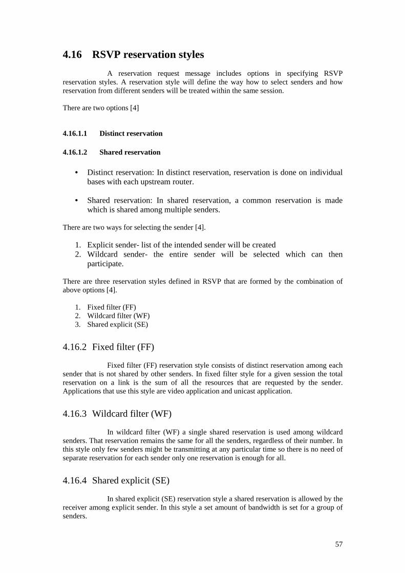
57
4.16 RSVP reservation styles A reservation request message includes options in specifying RSVP reservation styles. A reservation style will define the way how to select senders and how reservation from different senders will be treated within the same session. There are two options [4]
4.16.1.1 Distinct reservation
4.16.1.2 Shared reservation
• Distinct reservation: In distinct reservation, reservation is done on individual bases with each upstream router.
• Shared reservation: In shared reservation, a common reservation is made
which is shared among multiple senders. There are two ways for selecting the sender [4].
1. Explicit sender- list of the intended sender will be created 2. Wildcard sender- the entire sender will be selected which can then
participate. There are three reservation styles defined in RSVP that are formed by the combination of above options [4].
1. Fixed filter (FF) 2. Wildcard filter (WF) 3. Shared explicit (SE)
4.16.2 Fixed filter (FF) Fixed filter (FF) reservation style consists of distinct reservation among each sender that is not shared by other senders. In fixed filter style for a given session the total reservation on a link is the sum of all the resources that are requested by the sender. Applications that use this style are video application and unicast application.
4.16.3 Wildcard filter (WF) In wildcard filter (WF) a single shared reservation is used among wildcard senders. That reservation remains the same for all the senders, regardless of their number. In this style only few senders might be transmitting at any particular time so there is no need of separate reservation for each sender only one reservation is enough for all.
4.16.4 Shared explicit (SE) In shared explicit (SE) reservation style a shared reservation is allowed by the receiver among explicit sender. In this style a set amount of bandwidth is set for a group of senders.

58
4.17 RSVP message format RSVP comprises a common header that consists of 32-bit words. Following is the RSVP header format. Table 6: RSVP Message Format
4 4 8 16 16 8 8 32 16 1 16
Version Flag Type Check sum
Length Reserved Send TTL
Message ID
Reserved MF Fragment offset
• Version: 4 bit field that represents the protocol version number.
• Flags: 4 bit field (flag bits are still undefined yet)
• Message Type: 8 bit field that can have six possible values.
• Checksum: 16 bit field used to specify standard TCP/IP checksum for RSVP.
• Length: 16 bit field used to represent the packet size of RSVP in bytes.
• Send TTL: 8 bit field represents the time to live value of the message.
• Message ID: 32 bit field provides a label that is shared by all fragments of one
message from a given RSVP hop.
• More fragment (MF): 1 bit field that is reserved for message.
• Fragment offset: 24 bit field used to represent offset bytes for the message.
RSVP message field values are shown in the following table. Table 7: RSVP Message Field Attributes
Value Message Type
1 Path
2 Reservation request
3 Path error
4 Reservation request error
5 Path teardown
6 Reservation teardown
7 Reservation request ACK
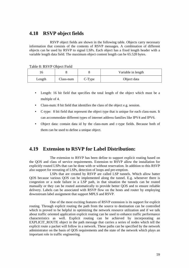
59
4.18 RSVP object fields RSVP object fields are shown in the following table. Objects carry necessary information that consists of the contents of RSVP messages. A combination of different objects can be used by RSVP to signal LSPs. Each object has a fixed length header with a variable length data field. The maximum object content length can be 65.528 bytes. Table 8: RSVP Object Field
16 8 8 Variable in length
Length Class-num C-Type Object data
• Length: 16 bit field that specifies the total length of the object which must be a
multiple of 4.
• Class-num: 8 bit field that identifies the class of the object e.g. session.
• C-type: 8 bit field that represent the object type that is unique for each class-num. It
can accommodate different types of internet address families like IPV4 and IPV6.
• Object data: contain data id by the class-num and c-type fields. Because both of
them can be used to define a unique object.
4.19 Extension to RSVP for Label Distribution: The extension to RSVP has been define to support explicit routing based on the QOS and class of service requirements. Extension to RSVP allow the installation for explicitly routed LSPs that can be done with or without reservation. In addition to this RSVP also support for rerouting of LSPs, detection of loops and pre-emption. LSPs that are created by RSVP are called LSP tunnels. Which allow batter QOS because various QOS can be implemented along the tunnel. E.g. whenever there is congestion or a node failure in a LSP path, in that situation the tunnels can be routed manually or they can be routed automatically to provide better QOS and to ensure reliable delivery. Labels can be associated with RSVP flow on the hosts and router by employing downstream label assignment that support MPLS and RSVP. One of the most exciting features of RSVP extension is its support for explicit routing. Through explicit routing the path from the source to destination can be controlled which is proved to be helpful in optimizing the network resource utilization and if we talk about traffic oriented application explicit routing can be used to enhance traffic performance characteristics as well. Explicit routing can be achieved by incorporating an EXPLICIT_ROUTE object in the path message that carries a series of nodes which tell the explicit route a packet will follow in a network. These paths can be specified by the network administrator on the basis of QOS requirements and the state of the network which plays an important role in traffic engineering.
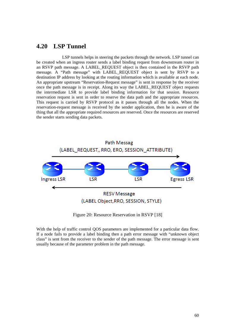
60
4.20 LSP Tunnel LSP tunnels helps in steering the packets through the network. LSP tunnel can be created when an ingress router sends a label binding request from downstream router in an RSVP path message. A LABEL_REQUEST object is then contained in the RSVP path message. A “Path message” with LABEL_REQUEST object is sent by RSVP to a destination IP address by looking at the routing information which is available at each node. An appropriate upstream “Reservation-Request message” is sent in response by the receiver once the path message is in receipt. Along its way the LABEL_REQUEST object requests the intermediate LSR to provide label binding information for that session. Resource reservation request is sent in order to reserve the data path and the appropriate resources. This request is carried by RSVP protocol as it passes through all the nodes. When the reservation-request message is received by the sender application, then he is aware of the thing that all the appropriate required resources are reserved. Once the resources are reserved the sender starts sending data packets.
Figure 20: Resource Reservation in RSVP [18]
With the help of traffic control QOS parameters are implemented for a particular data flow. If a node fails to provide a label binding then a path error message with “unknown object class” is sent from the receiver to the sender of the path message. The error message is sent usually because of the parameter problem in the path message.

61
4.21 RSVP-Extended path message Path message that is generated by the ingress router with the SESSION type LSP_TUNNEL_IPV4 consists of the following objects.
4.21.1 LABEL_REQUEST object:
A LABEL_REQUEST object is contained in the RSVP path message. A “Path message” with LABEL_REQUEST object is sent downstream to request a label by RSVP to a destination IP address by looking at the routing information which is available at each node.
4.21.2 EXPLICIT_ROUTE object:
Explicit routing can be achieved by incorporating an EXPLICIT_ROUTE object in the path message that carries a series of nodes which tell the explicit route a packet will follow in a network. These paths can be specified by the network administrator on the basis of QOS requirements and the state of the network which plays an important role in traffic engineering.
4.21.3 SESSION_ATTRIBUTE object: This object is used in identification and monitoring of the session. With the help of session attribute object holding properties, local routing features and path setup properties are also controlled.
4.22 RESV-Extended Message In response to the “path message” the egress LSR transmits RESV-Extended Message towards ingress LSR. RESV-Extended Message incorporates the following objects:
• LABEL object: responsible for downstream label distribution process.
• RECORD_ROUTE object: LSP’s path is returned to the sender from the path message.
• SESSION object: unique identification of label switch path being established.
• STYLE object: indicates the reservation style i.e. fixed-filter or shared-explicit style.
4.23 Carrying label information in BGP-4 Border gateway protocol (BGP) is an exterior routing protocol in use today. TCP protocol is used on port number 179 by BGP. During the establishment of the BGP peers, routing information tables are exchanged completely. BGP routers does not send

62
periodic updates, updates are send only when there is any change in those information tables, BGP routers sends only that new information to their neighbors. Only the optimal path to the destination is advertised. In order to increase scalability BGP can be used to advertise a particular route, it may also be used for the distribution of label that is mapped to the router. So on the new route update message, this label mapping information is piggybacked. Label distribution using BGP has the following benefits.
• Label distribution can take place without a label distribution protocol only when the two LSRs are adjacent and BGP peers.
• When the exterior LSRs are BGP peers then the interior LSRs need not to receive any of the BGP routes from the peers if the external peers distributes label among themselves.
• BGP advertise the new route and with this advertising the label mapping information
is also piggybacked. This piggybacking on BGP updates is done by using BGP-4 multi-protocol extension attributes.
Whenever an update message is send between BGP routers the Network Layer Reach-ability information (NLRI) is also exchanged. Labels are encoded in NLRI and the Subsequent Address Family Identifier (SAFI) specifies the presence of that label [5].
Figure 21 distribution of labels between non-adjacent BGP peers [17]
4.24 Label Information Network Layer Reach ability Information (NLRI) carry the label information in the BGP-4 extension protocol attributes. An NLRI consists of LENGTH and PREFIX, where the length represents the network mask to indicate the number of network bits whereas the prefix represents the network address of the subnet [5].

63
Following figure show a picture of the NLRI:
Length (1 octet)
Label (3 octet)
Label Stack
Prefix (Variable)
Network Layer Reach-ability Information
4.25 Constraint Based Routing (CBR)
Since link state routing protocols like OSPF and IS-IS lack in distributing the label binding information because they flood their information to all router those are running link state process. On the other hand distance vector protocol such RIP, RIP V2 and IGRP are suitable for transmitting label information between routers that are not directly connected but an extensive modification is required in order to transmit label binding information. For traffic engineering in MPLS it is necessary to perform the distribution of constraint based routing information to find the most suitable path in the network to avoid load, congestion and to obtain the optimal delivery. When we talk about constraint based routing (CBR) parameters like bandwidth, delay, QOS, and hop count etc also come to consideration [12]. With the help of CBR the traffic engineering demands (like QOS guarantee) in MPLS network are met. Explicit routing is an integral part of CBR where a route from source to destination is computed before setting up the LSP based on metrics.
To setup explicitly routed LSPs, a derivation from the LDP is “Constraint based Routing (CD-LDP)” used by the network managers in the management of sensitive traffic. Once the path is determined signaling protocols such as LDP or RSVP are used to setup Explicitly Routed Label Switched Paths (ER-LSPs), from the ingress to the egress node. When the underutilized links in the network will be used by the ER-LSR then proper utilization of the network takes place.
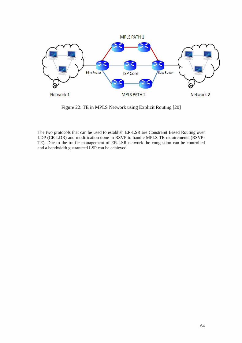
64
Figure 22: TE in MPLS Network using Explicit Routing [20]
The two protocols that can be used to establish ER-LSR are Constraint Based Routing over LDP (CR-LDR) and modification done in RSVP to handle MPLS TE requirements (RSVP-TE). Due to the traffic management of ER-LSR network the congestion can be controlled and a bandwidth guaranteed LSP can be achieved.

65

66
5 CHAPTER 5
In this chapter an overview of conventional routing techniques along with their problems will be discussed. The idea behind the algorithm, the different modes of operation and the problem addressed there will also be discussed in detail. Conventional routing Techniques There are two terminologies or classes of routing protocol over which the conventional routing techniques rules. They are
1. Distance Vector Routing 2. Link State Routing
5.1 Distance Vector Routing Distance vector routing protocol is a protocol that is used for communication in packet switched networks. In distance vector routing the distance and direction to any link in the network is calculated by means of various route metrics like hop count, delay and available bandwidth. In distance vector routing protocol Bellman Ford algorithm is used to calculate the paths [6] in the network and a routing table is maintained at each router that list all the possible destinations.
In Distance vector routing protocol the router not only informs its neighbors about change in the topology but also it let the router to broadcast periodic updates. With these updates all the routers in the network updates themselves. The routing algorithm computes the shortest path from the source to destination by comparing the distance received from each router and after calculating determine the next hop.
5.1.1 Problems in Distance Vector Routing
1. Distance vector routing protocol does not emphasize on the whole knowledge of the network topology due to which a lot of time is wasted in converging the changes in the network topology.
2. In distance vector routing protocol it is unable to prevent routing loops because Bellman Ford algorithm does not allow it to do so.
3. Because of routing loops network suffers from “count to infinity” problem.
4. If a node is down the packet still keep on looping continuously around the network
because the transmitting node is unaware of the down (out of order) node.
5. Hop count is used as a metric whereas delay, bandwidth is not taken into consideration.

67
5.2 Link State Routing Link State routing protocol is a protocol that is used for communication in packet switched networks. Popular link state routing protocols are OSPF and IS-IS. In link state routing protocol Dijkstra routing algorithm is used to calculate the paths in the network and a routing table is maintained at each router that list all the possible destinations. In link state routing protocol every router is prepared to forward the packets. This is done in a way that each router has to maintain a graph map of the connectivity of the network. Updates are sent periodically by all the routers in the network about the status and any change in the topology. Updates are known as Link State Advertisement (LSA) which includes the identification of the producing node and the directly connected nodes. When an update is in possession of a router it will look at its map which it has maintained and made appropriate changes and re-compute the routes according to the updates. Now it is much easy for each router to calculate the best next hop for the packet destination by looking at its routing table. Individually each node runs the algorithm to find the shortest path from itself to every other node. If we look at distance vector routing this method is easy and much more reliable and is less bandwidth intensive.
5.2.1 Problems in Link State Routing 1. In order to map the whole network the router need to have more memory.
2. Each router sends the LSA periodically which is a bandwidth issue.
3. Whenever there is an update about the link failures or link establishment updates are
send, these LSA may leads to inconsistent path decision and synchronization problems.
4. In an unsynchronized state in the large network due to the periodic updates routing can never be made inefficient.
5.3 IP Routing Problems and Solutions In conventional routing packets are routed on the bases of destination address and a single metric like hop-count or delay, only a single agenda is taken into consideration. The drawback of this conventional routing is that this approach causes traffic to converge into the same link which as a result becomes a reason for significant increase in congestion and leaving the network in a state of as an unbalanced network resource utilization condition.
QOS issues like performance of network and resource utilization are given much less importance. In conventional IP networks routing is done simply on the basis of destination address and a simple metrics such as hop count and delay. In hop-by-hop a sender wants to send a data packet from A (source) to B (destination) encountering a number of routers, as the packet heads the number of hop continue to decrease and at each router it looks for the next hop that is closest to the destination B till it reach its destination. While looking for the next hop, definitely it will be the closest neighbor to the destination, factor like congestion are not taken into account which in result left the packet to follow that route which is highly congested because it is the one closest to its destination, additionally the route lookup is a time consuming process. The widely used shortest path algorithm tends to cause such situations in the network.

68
Figure 23: Unequal Load distribution [20]
In the above figure it is quite clear that C-D-G is the shortest path with minimum number of hops. In conventional routing all the packets are directed outwards whose destination address share the same prefix and have the same subsequent hop. All the traffic will follow C-D-G path, even when C-E-F-G is much better option to distribute the traffic uniformly across the network and to achieve performance and better resource utilization.
Since all the packets are not created equally i.e. they vary in length and size like
packets carrying voice and video are different from those packets carrying data. So following the conventional routing approach they may not be able to reach their destination in the order and time to meet the application need because voice and data should be given priority over normal data packets, if not, they can get stuck behind normal data packets whose quality of service (QOS) requirements are not too high or sensitive. This is what makes conventional IP packet forwarding ill suited for current large scale revenue generating application such as VOIP and video conferencing. The solution to this problem is provided by Traffic Engineering (TE), which ensures bandwidth guarantee, explicitly routed Label Switched Path (LSP) and an efficient utilization of network resources.
Due to the high demand for background speeds, current research focuses on traffic
engineering with LSPs for batter control over the traffic distribution in the network. However the increase in the number of users of internet is driving the ISPs to adapt new technologies in order to support multiple classes of application with different characteristics and performance requirements. MPLS based approach to TE is the Overlay Model. Virtual networks are better option in MPLS for service provider for explicit routing which includes a full mesh of logical connection between LERs. Explicit routing provides an edge over traffic engineering objective over physical network which also help in uniform distribution of traffic across all trunks. Following figure shows an MPLS-TE overlay approach in which all the pair edge devices construct a virtual network through logical connections (LSPs) with explicit control over the specific routes.

69
Figure 24: MPLS Overlay Model
In conventional routing packets are routed on the bases of destination address and a
single metric like hop-count or delay, only a single agenda is taken into consideration. The drawback of this conventional routing is that this approach causes traffic to converge into the same link which as a result becomes a reason for significant increase in congestion and leaving the network in a state of as an unbalanced network resource utilization condition. QOS issues like performance of network and resource utilization are given much less importance. This approach works fine with best-effort model.
For explicit route it is necessary for the ingress router to understand the current
underlying topology and the available capacities. Shortest path algorithm uses the shortest path making that path overloaded while the other link remains underutilized. Due to Service Level Agreement (SLA) and QOS requirements the major drawback in conventional routing protocol is in ER-LSP because the LSPs are more sensitive to overall state information and the link residual capacities. Periodic updates do not mean that the residual capacities or state information are accurate because the state of the node may change any time additionally periodic updates results in high overhead and give rise to high loss rate, delay, jitter and bandwidth. LSPs fail because of inaccurate measurements, global state and residual capacities.
If we look deeper and have an analysis of the network then we will see that there are less frequent changes in the topology than the bandwidth itself. Finally in order to ensure bandwidth guaranteed tunnel with RSVP the reservation request need to be initiated by the receiver. The receiver then select an optimal route among all the possible routes from the

70
source to the destination, based on QOS requirement and network load conditions in order to provide reliable service to the user and also for uniform distribution of the traffic.

71
72
6 CHAPTER 6
6.1 MPLS Traffic Trunk In the third chapter we momentarily discuss TE and at the moment in this chapter we are going to thrash out the basic functions of TE and its components. A traffic trunk (TT) is a collection of traffic flows of the same category which are located within a label switched path.
A TT is a conceptual illustration of traffic to which explicit characteristics can be coupled. Think about if we examine a TT as things that can be routed, this is the course during which a traffic trunk traverses can be changed. TT is the same as virtual circuits in ATM and Frame relay networks. There is a differentiation among a TT, path and the LSP on the basis of which it traverses in the network because these terms “LSP” and “traffic trunks” are often used synonymously.
6.1.1 Attributes and uniqueness of TT This session desirable the attributes that can be associated with traffic trunks to manipulate and influence the behavioral characteristics of TT. TT exhibits the following properties.
• A traffic trunk can be described as an aggregation of traffic flows that
belongs to that particular class. It may be desirable to lighten up this
classification and allow TT to aggregate multi-class traffic.
• For a single class service model e.g. the current internet, a TT can
encapsulate all the traffic between an Ingress node and an Egress node, or
subsets accordingly.
• TT is a routable object similar to ATM VCs.
• TT is different from the LSP in a way through which it traverses. In
operation a TT can be moved from one path onto another.
• A TT conceptually never exhibit bidirectional characteristics that’s why it is
always unidirectional.
• A TT can be summarized as a part of the group through its Ingress LSRs and
Egress LSRs, the FEC over which it is mapped and a set of attributes which
determines its behavioural characteristics.

73
There are two significant issues
1. Parameterization of TT. 2. Placement of path and rules of maintenance for TT.
6.1.2 Bi Directional Traffic Trunks As discussed earlier conceptually TT is unidirectional in practical context, however it is useful to concurrently instantiate two TT having the same destinations (end points) rather carrying packets in reverse directions. This can be done through logical coupling of the two TT. Where the first one is known as the forward trunk for carrying traffic from an source node to the destination node. The second trunk is known as the backward trunk which works in an opposite way like it is responsible for carrying traffic from the destination node to the source node.
• Both forward trunk and the backward trunk are instantiated by an atomic
action at the source LSR, or they can be instantiated through an atomic action
at a network management station.
• None of the two TT (forward and backward TT) can exist independently
without each other. This means that both are instantiated at the same time and
destroyed together at the same time.
It should be kept in mind that bidirectional traffic trunks (BTT) are purely a managerial ease. When put into practice, major traffic engineering principals can be applied using only unidirectional traffic trunks.
6.2 Basic Operations The fundamental operations on traffic trunks with respect to traffic engineering purpose are discussed below.
• Establish: Instance creation of TT.
• Activate: letting the traffic trunk to pass traffic. To establish a traffic trunk
and to activate it, are separate events logically and hence can be applied by
one atomic action.
• Deactivate: Reverse of activation that mean don’t letting the traffic to pass
through traffic trunk.
• Modify Attributes: Causing the attributes of a traffic trunk (TT) to be
changed.
• Reroute: To cause a TT to adopt alternative route. This can be achieved
through managerial action or repeatedly by the underlying protocols.
74
• Destroy: In the destroy operation the instance of TT is removed retrieve all
resources assigned to it from the network. Those resources include label
space and available bandwidth associated to that instance of TT.
The preceding are some of the basic operation of traffic trunks. There are additional operations are also possible with TT such as policy and traffic shaping. Accounting and performance Monitoring
In order to account for the traffic characteristics function the accounting and performance monitoring capabilities are very important. Traffic characteristic uses the performance statistics that are gained from the accounting and by monitoring the performance of the system. Obtaining statistic at the traffic trunk level plays an important role in engineering traffic in MPLS.
6.3 Basic Traffic Engineering Attributes of Traffic Trunks
Basic traffic engineering attributes are those parameters that are assigned to it to
manipulate its behavioral distinctiveness. That can be specifically assigned to TT by the protocol through an administration action. That assignment is done when the classification and mapping of packets for their relative equivalence classes are undertaken at the ingress node while entering into an MPLS domain. Traffic engineering does not take into consideration of how the attributes are originally assigned, because it is obvious that these attributes can be changed for the purpose of traffic engineering through an administrative act lately.
Basic attributes of TT whose most part is significant for TE are listed below.
• Attributes of Traffic parameter.
• Basic path choice and preservation attributes.
• Equivalence class attributes.
• Flexibility attributes.
• Policing attributes.
• Pre-emption attributes.
A blend of traffic parameters and policing attribute’s mixture is equivalent to usage parameter control in ATM networks. Relatively it should be very clear to map the TT attributes into many on hand switching and routing architectures. Priority and pre-emption can be categorized as; there exists some sort of a relation between these two attributes because they exhibit definite binary relations among traffic trunks. Logically, these relations determine the approach in which TT interact with one another as they struggle for network resources for the period of path establishment and path maintenance.

75
6.3.1.1 Traffic parameter attributes Traffic parameters are used to confine the characteristics like forwarding equivalence class of traffic streams to be carried out through the traffic trunk. In order to count for equivalence class parameters like max out rates, usual rates, permissible burst size etc. From a traffic engineering point of view, the traffic parameters are very important because they take into to consideration the resource requirements of the TT. This is helpful for the allocation of resources and also helpful in avoiding congestion via preventative policies. For bandwidth allocation, a single value for the canonical bandwidth requirement can also be computed via TT's traffic parameters. There are well known techniques for performing these calculations. Example of this is the theory is the technique of effective bandwidth.
6.3.1.2 Basic Path Selection and preservation Attributes
Basic path selection and preservation attributes illustrates the rules for choosing the route taken by a TT as well as the rules for preservation of paths that can already be established. Paths are calculated automatically by the existing routing protocols or they can be explicitly defined via administrative means through a network operator. Several conditions applies like if there are no resource requirements or limitations associated with a TT, then a topology driven protocol can be used for the selection of path. On the other hand if, there resource requirements or policy limitation exists, then path selection must be carried out via constraint-based routing scheme. Path supervision concerns all aspects pertaining to the protection of paths traversed by TT. In some operational contexts, it is advantageous that an MPLS implementation can be configured dynamically by itself and become accustomed to some notion of change according to the current state of the system. Adaptability and flexibility are aspects of dynamic path management. To direct the path selection and administration process, some attributes are required. The generic attributes and behavioral characteristics related with traffic trunk path selection and administration are of major concern.
6.3.1.3 Adaptivity Attribute
Network distinctiveness and condition change over time e.g. new resources become there over time, unsuccessful resources become activated again, and previously allocated resources become de-allocated again. In broad-spectrum, from time to time more efficient paths become available whenever there is a state changes from one to the other. Consequently, from a Traffic Engineering point of view, it is mandatory to have administrative control parameters though used to identify how traffic trunks act in response to this dynamism. In some situations it might be advantageous to dynamically change the paths of some traffic trunks according to the changing state of the network. Through this process re-optimization can be achieved. In another situation, re-optimization might not be fruitful. An adaptively attribute is an element of the path preservation parameters in charge with traffic trunks. The adaptivity attribute that are related with a traffic trunk points whether the trunk is needed to be re- optimized. This makes adaptivity attribute a binary variable which acquire one of the subsequent values
6.3.1.3.1 Permit re-optimization
6.3.1.3.2 Disable re-optimization.

76
If we enable re-optimization, then a TT can be rerouted via diverse paths by the underlying protocols according to the changes in the current state of network (most significantly changes in the availability of resources). On the contrary, if there is a need of re-optimization, then the traffic trunk is "pinned" to its conventional path and cannot be routed again with respect to changes in network state. Eventually the major concern is stability when re-optimization is allowed. To encourage stability in a network, an MPLS execution must not be too immediate to the evolutionary dynamics of the network. Concurrently, there must be fairly fast mechanism so that optimal use can be made possible for the network assets. This indicates that the occurrence of re-optimization should be configured administratively to allow for tuning.
It must also be noted that re-optimization is distinct from flexibility and elasticity. There are different attribute that are used to identify the resilience characteristics of a traffic trunk. It seems practical to look forward to traffic trunks that are subject to re-optimization to be implicitly flexible to failures along their paths. On the other hand a traffic trunk which is not an issue of re-optimization and whose path is not specified by the administration by a "mandatory" attribute is vital to be resilient to that link and node failures in its established path.
On the record it is ok to say that adaptivity to state development via re-optimization give rise to resilience to failures, but formally resilience to failures does not mean general adaptivity via re-optimization to state changes.
6.3.1.4 Load Distribution across Parallel Traffic Trunks
Load division across multiple parallel traffic trunks between two nodes is a major issue to think about. It is practically impossible that the aggregate traffic between two nodes can be carried by a single link so it is not possible for that link to bear the load. The aggregate flow less than the maximum permissible but it might be possible that the aggregate flow of traffic across that link is less than the maximum allowable flow via the min-cut that partitions the two nodes. In this case the physically possible way out is to divide the aggregate traffic into sub streams properly and route the sub stream via various paths that amid the two nodes. In an MPLS, this hitch can be addressed by instantiating multiple traffic trunks between the two nodes as discussed earlier, in a way that each traffic trunk carries a percentage of the total traffic. Hence the problem is overcome by an elastic means to distribute the required load and assign it to numerous parallel traffic trunks shipping traffic between a pair of nodes. The underlying protocol is responsible for the proper distribution of the aggregate traffic load carried by each traffic trunk. There is a kind of micro flow is established for order the packet as well.
6.3.1.5 Equivalence class attribute
Relative importance of traffic trunks is defined by their class, which in fact represent their priority. In a constraint-based routing MPLS framework the priorities plays a very important role because they are used to find out the order in which path-choice is done for TTs, it is important for the establishment of connection and under fault scenarios. Precedence is also important in implementing pre-emption because they can be used to enforce a limited order on the set of TTs and on that basis preemptive policies can be actualized.
77
6.3.1.6 Pre-emption attribute
The preemption attribute determines that if a TT can preempt another traffic trunk from that specified path, and whether another TT can preempt a known TT. Preemption is valuable equally for traffic oriented and resource oriented performance. Preemption is done just to make sure that the traffic trunks for higher priority are always routed through the most favorable route within a differentiated services environment. Not only that preemption can also be used to put into operation various prioritized restoration policies that follows fault events. Four preempt modes are specified under preemption attribute for a traffic trunk they are as follows
1. preemptor enabled 2. non-preemptor 3. Preempt-able 4. non-preempt-able
Lower priority traffic trunks designated as preempt-able cab be preempted by a preemptor enabled traffic trunk. If a particular traffic is specified as non preempt-able then it cannot be preempted by other traffic trunks, in spite of relative priorities. Higher priority trunks those are preemptor enabled can preempt a traffic trunk designated as preempt-able.
It is insignificant to see that few of the preempt modes are jointly exclusive. The reasonable preempt mode combinations for a given traffic trunk by means of the numbering method depicted above, they are as follows (1- 3), (1- 4), (2- 3) and (2- 4). Where (2, 4) combination is the default (exception). A traffic trunk "X" can preempt any other traffic trunk "Y", only if the following five conditions are held completely
1. "X" having higher priority than "Y" 2. "X" contends for a resource utilized by "Y" 3. the resource cannot at all accommodated at the same time "X" and "Y" are
based on certain conclusion criteria 4. "X" is preemptor enabled 5. "Y" is preempt-able
Preemption is useful but it is not thought to be a mandatory attribute under the current best effort Internet service model but in a differentiated services situation, it become compulsory. In optical internetworking architectures, where protection and restoration functions are migrated from the optical layer(such as gigabit and terabit label switching routers) to data network elements to decrease the costs, under fault conditions the restoration time can be reduced for high priority traffic trunks through preemptive strategies.
6.3.1.7 Resilience Attribute
Under fault conditions the resilience attribute is used to determine the behavior of a traffic trunk i.e. when a fault occurs along the traversing path of the traffic trunk. There are few problems that are required to be addressed under such particular circumstances, these are

78
1. Detection of fault 2. Notification of failure 3. Recovery mechanism and service restoration
It should be very clear that an MPLS realization will have to integrate mechanisms to address these matters. There are many recovery policies that can be particularly for traffic trunks whose conventional paths are impacted by faults. Here are few examples of feasible schemes
1. Avoid rerouting traffic trunk e.g. a scheme may already be in place for the trunk to survive, provisioned via an alternating mechanism that guarantees service stability in case of failure without rerouting traffic trunks. One of the examples of such an alternating scheme is a scenario where several parallel LSPs are provisioned among two nodes, and function in such a manner that failure of one LSP makes the TT (placed on it) to be mapped onto the left over LSPs according to any well defined policy.
2. Rerouting should be done to make sure that the feasible path is equipped enough resources. If there is no feasible path available then do not reroute.
3. Rerouting can be done through any available path irrespective of resource constraints.
4. There may be several other arrangements are possible including some which might be in association of the above.
The "basic" resilience attribute specify the revival course of action to be applied to traffic trunks whose paths are influence via faults. Categorically, this resilience attribute is a binary variable which identifies whether the aimed traffic trunk is to be rerouted when section of its path fails. The "Extended" resilience characteristic can be used to indicate convoluted measures to be taken under fault situations e.g. The overhead attribute potentially indicates a set of substitute paths to use under fault conditions, as well as the rules that governing the relative execution of each specified path. It must be appreciated that the resilience characteristics dictate close communication between MPLS and routing.
6.3.1.8 Policing attribute
Policing characteristic pins down the actions that can be taken by the original protocols when a traffic trunk becomes non-compliant i.e. when a traffic trunk overweight its agreement as indicated in the traffic parameters. Normally, policing attributes can specify when a non-conformant TT can be rate limited, tagged, or just forwarding without any course of action. If any policing is employed, then adaptations of established algorithms can be used in order to perform this function. Course of action is mandatory in several operational situations, but is often unwanted in some other situations. In common, it is usually advantageous to apply the course of action at the ingress node to a network which helps in the enforcement of the compliance with SLA and to lessen policing within the core only when capacity constraints order otherwise. As a result, from a Traffic Engineering viewpoint, it is essential to allow enabling and disabling the traffic policing for each traffic trunk administratively.

79
6.3.1.9 Resource Attributes
The Resource attributes belongs to the topology state parameters, which are used to restrict the routing of TT through particular resources.
6.3.1.9.1 Maximum Allocation Multiplier
The maximum allocation multiplier (MAM) of a resource is an attribute that can the administratively configured that identifies the percentage of the resource that is accessible for allocation to TT. This characteristic is mostly suitable to link bandwidth. On the other hand, it can also be applicable to buffer resources on LSRs. The conception of MAM is comparable to the impression of subscription and booking element in Frame Relay and ATM networks. The principles of the MAM can be elected according to the under- allocation or over-allocation of resources. Under- allocated resources are those resources required when the combined load of all traffic trunks that can be assigned to it must always be less than the capability of the resource. Whereas resources are said to be over-allocated when the collective demands of all traffic trunks (as expressed in the trunk traffic parameters) assigned to it can go beyond the capability of the available resource. Under-allocation can be used for resource utilization. But in MPLS the scenario is more difficult than in circuit switched pattern because in MPLS, some flows can be routed through regular hop by hop protocols (also via explicit paths) without taking into consideration the resource constraints. By means of over-allocation advantage over the statistical characteristics of traffic can be taken when putting into practice more efficient resource allocation course of action. In general, over-allocation give rise to a scenario where the high demands of traffic trunks do not correspond in time.
6.3.1.9.2 Resource Class Attribute
Parameters of Resource class attributes are assigned administratively which put across some notion of "class" for resources. Resource class characteristics can be viewed as "colors" registered to resources such that a group of lay down resources with the same "color" theoretically belongs to the same class. Class attributes can therefore be worn to put into practice a variety of policies. The input resources of concern here are links. When applied to links, these attribute successfully becomes a feature of the "link state" parameters. Resource class attributes represents a powerful abstraction of concept. If we look at a Traffic Engineering point of view, it can be carried out to realize many policies with respect to both traffic oriented and resource oriented performance optimization. Particularly these attributes can be realized as
1. Relate consistent policies to a set of resources that do not require being in the similar topological section.
2. State the relative preference of group of resources for path assignment of TT. 3. Clearly put a ceiling on the assignment of TT to explicit subsets of resources. 4. Employ comprehensive inclusion or exclusion policies.
80
5. Impose traffic neighbourhood restraint policies e.g. try to find policies that are looking for local traffic contained within particular topological area of a network.
In addition to above said points the Resource class attributes can be worn for detection and recognition purposes. In a broad-spectrum, resource can be register with multiple resource class attributes e.g. within a network all the OC-48 links might be assigned a notable and a separate resource class attribute. The subsets of OC-48 links having and existence within the same domain may be assigned supplementary resource class attributes for the purpose to implement specific course of action or it might be a form to build the network in a particular manner.
6.3.2 Constraint- Based Routing
In the discussion below we will focus on the issues related to constraint-based routing in MPLS domain. In modern-day language, CBR is habitually referred to as “QOS Routing”. CBR can capture the functionality envisioned in a better way, which normally incorporate QOS routing as a compartment. Constraint bases routing enables a paradigm that is demand driven and have resource reservation awareness, not only that it also allows the routing paradigm to co-exist with existing topology driven hop by hop IGP. There are some inputs for a constraint-based routing framework which are as follow
• Attributes association with traffic trunks.
• Attributes association with resources.
• Information regarding the topology condition.
A CBR process is then created where each node instinctively computes unambiguous routes for every TT originating from the node automatically. In such a situation a predefined route for each TT is a specification of a LSP that justifies the demand requisite mentioned in the trunks attributes, area under discussion are those constraints forced by resource availability, administrative strategy, and other state information of the topology. On the other hand a CBR skeleton can greatly decrease the level of physical configuration but still the involvement required to actualize TE policies. The T engineer or simply an operator can mention the endpoints of a TT and allocate a set of attributes which sum up the performance prospect and behavioral characteristics of the trunk. The CBR framework is then predicted to find a reasonable path to assure the expectations.
6.4 Implementation Considerations
Previously Commercial apparatus of switches in Frame Relay and ATM support some impression of constraint-based routing. For MPLS centric apparatus, it ought to be relatively easy, to broaden the current CBR implementations to put up the irregular of MPLS requirement. CBR can be integrated in the router those uses topology driven hop by hop IGPs by one of the following two ways
1. Extension of the current IGP protocols in such a way that it supports CBR like OSPF and IS-IS. Attempts are already in progress to provide such extensions to OSPF.
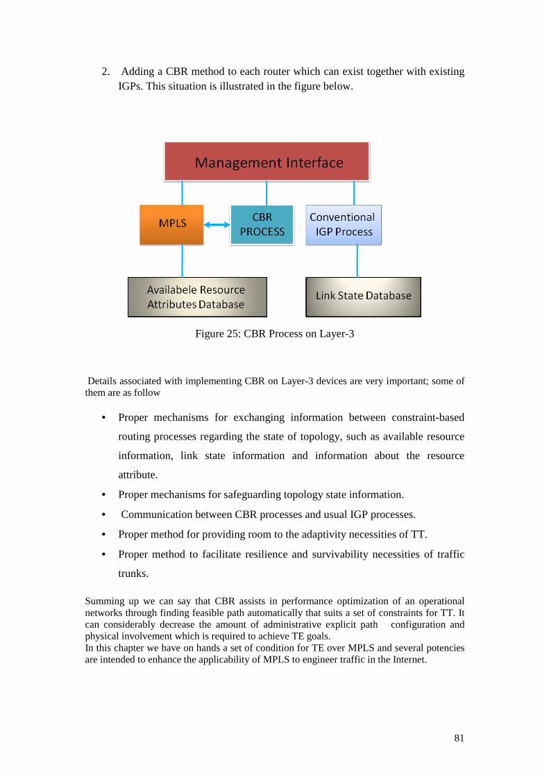
81
2. Adding a CBR method to each router which can exist together with existing IGPs. This situation is illustrated in the figure below.
Figure 25: CBR Process on Layer-3
Details associated with implementing CBR on Layer-3 devices are very important; some of them are as follow
• Proper mechanisms for exchanging information between constraint-based
routing processes regarding the state of topology, such as available resource
information, link state information and information about the resource
attribute.
• Proper mechanisms for safeguarding topology state information.
• Communication between CBR processes and usual IGP processes.
• Proper method for providing room to the adaptivity necessities of TT.
• Proper method to facilitate resilience and survivability necessities of traffic
trunks.
Summing up we can say that CBR assists in performance optimization of an operational networks through finding feasible path automatically that suits a set of constraints for TT. It can considerably decrease the amount of administrative explicit path configuration and physical involvement which is required to achieve TE goals. In this chapter we have on hands a set of condition for TE over MPLS and several potencies are intended to enhance the applicability of MPLS to engineer traffic in the Internet.

82
6.5 Multicast Traffic Engineering
A discussion of multicast traffic engineering with MPLS will be carried out in this chapter. When we talk about link cost there are certain things that come into mind so for the network performance it is a very important parameter. Audio / Video or teleconferencing require a massive amount of network bandwidth because of the transmitted data and secondly a large number of members to that application. Here Multicasting issue comes into consideration. Multicasting is service usable for supporting many applications. In multicasting a packet is sent to destinations and a single transmission however there are many transmissions required Uni-cast service. Multicast is a major corresponding technologies where multicast tree supported to MPLS networks and give rise to efficient network performance, multicast allow scalability and control overheads problem. Traffic Engineering is the controlling factor for the traffic that flows and also helps in optimizing network resource utilization. A CBR and an improvement in on hand IGPs may be required to allow Uni-cast forwarding through explicit routes.
6.5.1 Multicast TE
Multicast TE takes into account some assessment of network resource utilization, CBR algorithms and explicit routes. In multicasting the network topology and the shortest paths is taken into consideration. Multicast TE is just the same as the Uni-cast TE for efficient network resource utilization. There are multicast routing protocols that rely on reverse path forwarding (RPF) because they are based on symmetric concept for setting up forwarding states on middle or in between routers from the source and the destination. In practical when the routing constraints are applied, there is no surety that the link utilization is symmetric. RPF will provide the foundation forwarding on a sub-optimal path in QOS routing.
In multicast TE path failure is disastrous and a fast recovery mechanism for the failure path is very important. Since all the tree is influenced not only the link by the failure.
Multicast forwarding is done on the basis of destination IP addresses and so it is practically very difficult to aggregate multicast traffic because receiver of that cast can be located anywhere in the network. Multicast TE trees can be developed by intensifying on hand protocols. Two types of protocols can be setup
6.5.1.1 Sender initiated tree setup
Tree can only have inadequate number of receivers with very unusual join and prune action. Multicast trees can be calculated by the first- hop router from the starting place, which is based on advertisements of traffic from the sender side.
6.5.1.2 Receiver initiated tree setup
In receiver initiated tree setup there are large numbers of receivers who join and prune frequently. Multicast trees are calculated from destination to the source. Receiver’s end router autonomously computes a QOS and in-
83
cooperate path from the origin which is based on the reservation made by the receiver. This path can only be calculated on the basis of Uni-cast routing information when the path computation for multicast is broken up into multiple but concurrent Uni-cast paths.
MPLS label switching forwards uni-cast traffic via particular routes and the multicast traffic is forwarded down the explicit tree to stay away from RPF checking. Multicasting in MPLS networks can be helpful in settlement from the multicast reduce of traffic on one hand allowing MPLS flexibility, QOS and speed on the other hand. Aggregation, flooded and prunes, coexistence of source and shared tree, Uni / Bi directional shared trees, encapsulated multicast data and loop freeness, and RPF check are the characteristics that are considered when MPLS techniques that are applied to IP multicast. Multicast MPLS has many benefits not only in reducing multicast forwarding states but also for TE and QOS issues.

84

85
7 CHAPTER 7
7.1 Issues in MPLS
In this chapter we will also discuss some issues in MPLS related to competence and load dependent parameters. Now we are very much proverbial with the formal and deep study of MPLS and its very important features LSP. Paths can be established in a number of ways through various control planes. LSP is a definite route, for a specific route it is said to LSP Tunnel (LSPT). It shares many attributes of ATM virtual channels. Which as a result make it possible to take forwarding decision on the basis of destination address as carried out in conventional IP
The multicast operation of MPLS is currently not defined. However, a general
approach has been recommended whereby an incoming label is mapped to a set of outgoing labels. This can be constructed via a multicast tree. In this case, the incoming label will bind to the multicast tree and a set of output ports is used to transmit the packet. This operation is quite conducive to a local-area-network (LAN) environment. In a connection-oriented network such as ATM, the point-to-multipoint switched paths (VCCs) can be used for distributing multicast traffic.
. MPLS has been modified for WDM optical networks also known as MPLS Lambda or more recently GMPLS.
7.1.1 Path Capacity and Load dependent parameters
In communication networks, switches or routers are abstract nodes, where as transmission lines no matter they are wired or wireless are called as link. A network communication is describe as a graph G= (N, L) where N is the number of node and L represents the set of links, graph can be represented in (0, 1) matrix called the incidence matrix that indicates an affiliation among links and node. Graph is used to analyze the network that’s usually augmented in a way that a set of quantitative entities are associated to node. Examples are link transmission capacity “Ci” and link traffic flow “λi”. The topology is occasionally regarded as being adjustable. It is feasible to build multiple types of network model on the basis of different arrangement of these entities.
In communication networks, four generic model being used widely
1. Capacity assignment (CA) 2. Flow assignment (FA) 3. Capacity and flow assignment (CFA) 4. Topology capacity and flow assignment (TCFA)
In CFA model the capacities and flows are decision variables. A most advantageous cost or throughput can be achieved by adjusting these variables if the related model is not a bound less one.

86
7.1.2 Load Dependent Parameters and Non Linear Models
From a mathematical view point, all the basic networks models can be interpreted as the shortest path setback. Standard model can be linear or non linear. These networks are independent of load parameter i.e. per unit flow cost or the length of links, then resulting model usually takes the form of linear programming. On the other hand if the network parameters are load dependent i.e. the mean or variance of delay, then the model may take form of nonlinear programming. There are limited numbers of nonlinear model in IP networks but these no linear models can play their role in MPLS networks.
7.1.3 Multi- Class Traffic and Path Capacity
Real time supplies and requirements in multimedia communication have a great effect in multi-class traffic flows. These multi dimension diverse flows will navigate all links associated with a single particular origin-destination (OD) pair. It is quite clear from a mathematical calculation that the total number of paths in any network is usually large in quantity than the total number of links. In FA model the link flows ( λi) are expressed by path flows (Xk). Since Xk is a design variable, FA models incorporate with the stochastic programming tactic.
CFA model communication capacities are processed as design variables. It is more suitable to use path capacities as design variables for the replacement of link capacities because the special effects of link capacities on the assignment over path flow become confusing. This advancement seems on the whole as natural for MPLS networking problems since the path capacity concept is related directly to the label switched path provisioning.
7.1.4 GCFA: Capacity and Flow Assignment Model From a network optimization prospectus there are two main features to be considered
1. the Capital Index 2. the operating index
In practice both the index can be used as the objective function, having the other one as constraint. Both the indexes can be chosen on the basis of priority of objectives and availability of bonded values. E.g. If capital index is selected to be the objective function, then we have a generalized shortest path problem in the model, because the distance assigned to each link could be geographical distance, the unit traffic flow cost, the utilization ratio. Mathematically there are numerous ways to elaborate a GCFA model. The process of discarding a packet is one of the main reasons of congestion in network based on packet switching protocols. GCFA consider the priority issue regarding space, reflected by the packet discard ratio. In broad-spectrum there is no analytical solution for GCFA, because of the system inequality constraints about flows. Capacity Assignment Model GCA GCA may have analytical solutions if path flows are allocated according to an independent protocol. The multi-class paradigm can be treated by
1. Differentiating space priorities on the basis of paths that connect the same OD pair.
2. Differentiating space priorities on a set of layered optimization models. In latter case, for each layer a standardized priority is assigned to all traffic flows and the optimization is conducted.

87
7.2 Problem understanding, Future work proposed solution and CONCLUSION
Multicast and point-to-multipoint (P2MP) support was not incorporated in the inventive MPLS provision. Users wishing to transmit IP multicast traffic traversing an MPLS network were mandatory for them to set up point-to-point (P2P) LSPs starting the source point of the multicast traffic MPLS PE to each intended exit point (destination) MPLS PE. In point of fact, this made the source (ingress PE) the only replication face for all of the traffic in the multicast flow as shown below.
Figure 26: MPLS Multicast Traffic
. In the above diagram it is quite clear that there is an effective delivery of multicast traffic yet it is not good at its job because the source PE is put under increasing tension by calculating route for extra destination PEs and by the provisioning of new multicast flows. And this thing is very important for a provider’s point of view because the network resources are poorly utilized, that is visible from the above diagram, showing how the PE1 is under a heavy load of replicating the traffic because of multiple target destination. In our example the source is carrying three copies of the data which results in three LSPs,
1. PE1-PE2 2. PE1-PE3 3. PE1-PE4

88
This form of solution is not suitable for large networks because it is un-scalable. The link between X-Y carries two copies of the data because there are only two PE (PE2, PE3) in our network but with greater number of PEs more and more PEs will be participating in the multicast distribution which results in a heavy burden on the replicating PE. Other than that an inefficient use of bandwidth does not allow it to be an emerging technology and is unacceptable. However according to the current market demand multicast services are gaining popularity with the MPLS network providers. For VPN services multicast support is required, so multicast traffic must be carried out across the backbone in the MPLS network. Since voice and video distribution are entering the market, so the network service provider needs well-organized and valuable mechanisms to deliver those services across an MPLS network. With RSVP-TE it is now able to set up a P2MP LSP tunnels. To facilitate the support of multicast an introduction to the extensions to LDP and RSVP-TE can be done so that P2MP LSP signaling can be achieved. In the forwarding plane the LSP proceeds as it is created in regular MPLS network from the root (LSR-A), through LSR-B, to LSR-C.
Figure 27: P2MP LSP in MPLS Forwarding Plane The encapsulation rules and the forwarding rules for LSR-A and LSR-B are the same as in P2P LSP. LSR-C is a “Branch” node and is responsible for forwarding the packets to LSR-D and LSR-F. No method is specified for packet replication in the standard. In the figure LSR-F is an egress node also known as leaf node and has two IP networks in its downstream that are the target for the multicast flow, so LSR-F must perform IP replication
89
as well. There is also a special case when we talk about LSR-D because it is both an egress node of the P2MP LSP and also an intermediate point from the LSR-E prospective. Such type of node is called a “Bud” node. LSR-D must perform the forwarding mechanism on the LSP and also ensure local termination.
7.2.1 MULTICAST LDP In a forwarding plane the LSPs have a MP2P structure. There is a need of small modification to install a P2MP LSP in the elements and procedures of LDP. For this purpose a new FEC protocol element is defined which encodes an explanation of the multicast flow as identified the replicating node and a set of elements that will be used by an application in order to distinguish different flows from the same root. The information is relevant only for the leaves and the root. All nodes compare every FEC to differentiate P2MP flows. For this purpose the LDP label messages are improved so that they can carry the new P2MP FEC element which will help LDP to talk about P2MP LSPs. Label mapping is used to reach the root. It is an important to note that tree produced depends on the path directed from the egress to the root instead of the route from the root to the egress. Since MPLS-TE LSPs are signaled by RSVP-TE via a Path/Resv this fundamental rule is used for P2MP LSPs. Which allow the replicating source to know which destinations (leaves) are attached to the LSP. So here the problem arises, how this is achieved? Such a specification is not a part of the protocol but it can change according to the application. In P2MP RSVP-TE operation the basic node handles each leaf separately. For this the source (ingress node) calculates the route for a P2P LSP for every leaf from the source to destination and signals it. During the calculation at each hop if the signaled LSP encounter an already existing LSP for the same P2MP tree, then the LSP share the resources and labels. On the other hand at each hop if there is no pre-existing LSP then the Path/Resv messages will install a new LSP and hence new label is allocated for that LSP which is the same as in P2P LSP. The matter of concern is how the LSP is identified when two source-leaf LSPs for the common P2MP LSP coexists at a hop in order to achieve this some of the RSVP protocol fields can be modified slightly and also allow to examine that how forwarding-plane components are shared. This is a simple technique for the addition and removal of leaves. This technique comes with big issues firstly the P2MP LSP path is not perfectly optimal and the resultant tree only shows least cost to the destination which also fail in optimizing core network usage and the computation that take into consideration all destinations at one time in order to produce a Steiner tree. So far such a technique is feasible for small number of LSPs having a low number of leaves but with a large number of LSPs it will not be possible to manage the path messages. Solution is that a protocol should be extended in such a way that allows a Path/Resv message to carry required information about multiple cast destinations for a single P2MP LSP. For example, the following figure can be used to depict the source-to-leaf signalling mechanism situation in an easy manner for a P2MP tree.

90
Figure 28 P2MP LSP TREE
There can be six path messages with the following explicit routes:
1. A, B, C, D, L 2. A, B, C, E, M 3. A, B, C, E, F, J, N 4. A, B, C, E, F, K, O 5. A, B, C, E, F, K, O, P 6. A, B, C, E, F, G, H, Q
Using the Secondary Explicit Route objects (SERO) method we can compress the path information:
1. A, B, C, D, L 2. C, E, M 3. E, F, J, N 4. F, K, O 5. O, P 6. F, G, H, Q
There are two things that are of primary importance when path information is processed and each entry in the path list is determined:
1. In the path list if the LSR is the top next hop entry, and then it will creates a path message in order to carry the entry and processes the entry as an explicit path.

91
2. Else, the LSR will look for the path message which was created by it earlier that contains the next top hop entry. The path message that is found it copies the entry of the path list
On the reception of the path message the path list looks like:
1. C, D, L 2. C, E, M 3. E, F, J, N 4. F, K, O 5. O, P 6. F, G, H, Q
At the first path message the LSR-C will create a path message “1” and send it to “D” and another path message “2” will be created and send to “E”. A path entry is added to path message for “E, F, J, N”, “F, K, O”, “O, P” and “F, G, H, Q”. Similarly, like LSR-C at LSR-F, the following path entry list is received as: At F, J, N a path message is created and sends it to the next hop “J”. And for F, K, O another path message is created a send to K at O, P a path message entry is added to F, K, O and finally at F, G, H, Q another path message is created and send to G. This way P2MP problem can be resolved up to a great extend.
7.2.2 Conclusion It is concluded that when a Users wish to transmit IP multicast traffic traversing an
MPLS network it is mandatory for them to set up point-to-point (P2P) LSPs which makes the source (ingress PE) the only replication point (PE1 in figure 26) for all of the traffic in the multicast flow although this strategy comes up with an effective delivery of multicast traffic but it is not good at its job because the source PE is put under increasing tension by calculating route for extra destination PEs and by the provisioning of new multicast flows. Here comes the scalability issue. For a small network this situation can be handled very easily but the replication can create a major problem in large networks. Currently we are running short of resources we cannot afford to (from a provider’s point of view) have a network with poorly utilized resources. So there is a need of well-organized and valuable mechanisms to deliver those services across an MPLS network. LDP is a protocol that is used in MPLS network for the distribution of labels to setup P2P LSPs and allow each incoming packet to follow that path in order to make its destination so here there is a need of a small change in the underlying protocol so that P2MP traffic can be made possible in a timely and effective manner while keeping in mind the network constraints like bandwidth and delay. P2MP LSP tunnels should be setup by incorporating RSVP-TE and an introduction to the extensions in LDP to facilitate the support of multicast. Problem arises when a branch node in figure 27 has to forward the packets to LSR-D and LSR-F because there is no method specified for packet replication in the standard.
This technique described above comes with big issues firstly the P2MP LSP path is
not perfectly optimal and the resultant tree only shows least cost to the destination which also fail in optimizing core network usage and the computation that take into consideration all destinations at one time in order to produce a Steiner tree. So far such a technique is feasible for small number of LSPs having a low number of leaves but with a large number of LSPs it will not be possible to manage the path messages. There is a need for correlation of the echo responses at ingress so that the branch nodes can be identified in the P2MP tree and also some new flags like B flag for a branch node and E flags for a bud node to help the
92
downstream Mapping TLVs but another problem arises and that is the construction of the tree which is very hard in the correlation of Echo Responses.
Future work may possibly include an extension to the protocol in a way that allows a
Path/Resv message to carry required information about multiple cast destinations for a single P2MP LSP. On the other hand the egress filtering is achievable in P2MP RSVP-TE the LSR will only responds if and only if it lies in the pathway for the P2MP LSP so that the egress can be identified by the P2MP Egress Identifier TLV and it is possible since RSVP-TE identifies the destinations but egress filtering is not possible for multicast LDP. A transit LSR of a multicast LDP LSP is incapable to resolve the problem whether it lies on the pathway to any one destination. Only an Unfiltered full tree trace route is possible for the entire LSPs which results in many responses to ingress and it very hard to sort out which LSP hops belong where in the tree. One of the solutions to this problem is suggested earlier by indication the status using flags and can be done by specifying outgoing interface and label in Downstream Mapping TLV. By listing the possible destinations that are reachable through each outgoing interface or label new Downstream Mapping Multipath Information can be achieved.
In this thesis report our focus in MPLS network. We focus on MPLS with Traffic Engineering, QOS and issue of MPLS and try to provide meaning full thought regarding to the topic. During the thesis we analyze that MPLS provide efficient transmission, QOS, reliability scalability, fault tolerance, load distribution, path protection, End-to-end connectivity and marvelous achievement that provide connection oriented techniques with integration of IP networks. Point-to-multipoint (P2MP) support was not incorporated in the inventive MPLS provision. Users wishing to transmit IP multicast traffic traversing an MPLS network were mandatory to set up point-to-point (P2P) LSPs starting the source point of the multicast traffic MPLS PE to each intended exit point (destination) MPLS PE. We have discuss MPLS from a theoretical approach of TE and its component like LSR, LER, LSP, CR-LDP,RSVP, RSVP-TE, Labels and the necessities and the advantage of traffic engineering and its implementation with MPLS. General and some practical scenarios are analyzed and a deep study of MPLS with TE is carried out. To enhance the performance of networks an easy understanding of how traffic is mapped into any particular LSP is also discussed. In the end, we believe that MPLS utilize network resource more efficiently and minimize the congestion with a remarkable objective function for TE. It brings revolution and facilitates several services such as real time applications support in network.

93

94
Abbreviations
MPLS Multi-Protocol Label Switching LSR Label Switch Router NAP Network Access Point LDP Label Distribution Protocol FIB Forwarding Information Base VPN Virtual Private Network LIB Label Information Base LFIB Label Forwarding Information Base TTL Time To Live LSP Label Switched Path FEC Forwarding Equivalence Class PHP Penultimate hop popping VPI Virtual Path Identifier ISP Internet Service Provider MANs Metropolitan Area Networks VCI Virtual Circuit Identifier AS Access Routers POP Point of Presence VC Virtual Circuit TDP Tagged Distribution Protocol CEF Cisco Express Forwarding LC-ATM Label Control ATM OSPF Open Shortest Path First SOO Source of Origin IP Internet Protocol TE Traffic Engineering LER Label Edge Router LSP Label Switch Router LDP Label Distribution Protocol CR-LDP Constraint-based Label Distribution Protocol RSVP-TE Resource Reservation Protocol - Traffic Extension COS Class of Service PHB Per Hop Behavior Diffserv Differentiated services Resv Reservation VoIP Voice over Internet Protocol SERO Secondary Explicit Route Objects LANs Local Area Networks

95
References:
[1]. Wikipedia, “Internet backbone”. Free encyclopedia of information [Online].
Available: http://en.wikipedia.org/wiki/Internet_backbone [Accessed: March 25th, 2009]
[2]. L. Balliache. “Practical QOS”. CAIDA based at the San Diego Supercomputer Center (SDSC) on the campus of the University of California, San Diego [Online]. Available: http://www.opalsoft.net/qos/MPLS.htm [Accessed: 2nd April, 2009 at 6:00PM ]
[3]. Xipeng Xiao Hannan, A. Bailey, B. Ni, L.M. “Traffic engineering with MPLS in the Internet”. IEEE Network Magazine. Pub. Mar/Apr 2000. Vol. 14. Issue. 2. pp. 28-33.
[4]. Juniper Networks, “Technical Documentation: JUNOS 5.3 Internet Software Configuration Guide: MPLS Applications,” Juniper Networks Inc, 1999-2009. [Online]. Available: http://www.juniper.net/techpubs/software/junos/junos53/swconfig53-mpls-apps/html/swconfig53-mpls-appsTOC.htm. [Accessed: April. 17, 2009].
[5]. InetDaemon, “Tutorials by InetDaemon: BGP Update Message” InetDaemon”, 1996. [Online]. Available: http://www.inetdaemon.com/tutorials/internet/ip/routing/bgp/operation/messages/update/nlri.shtml. [Accessed: April. 20, 2009].
[6]. Wikipedia, “Internet backbone”. Free encyclopedia of information [Online]. Available: http://en.wikipedia.org/wiki/Distance-vector_routing_protocol[Accessed: April, 2009]
[7]. Wu, J.; Savoie, M.; Mouftah, H.T.; Montuno, D.Y.” Recovery from control plane failures in the CR-LDP and O-UNI signalling protocols”. DRCN 2003 Proceedings. Fourth International Workshop 19-22 Oct. 2003 pp. 139 – 146.
[8]. L. Andersson, P. Doolan, N. Feldman, A. Fredette and B. Thomas. “LDP Specification”, RFC 3036, January 2001
[9]. H. Jonathan Chao, Xiaolei Guo. Quality of service control in high-speed networks, illustrated ed. Reading, MA: Wiley-IEEE, 2001. [E-book] Available: Google e-book.
[10]. Reddy. Building MPLS-based broadband access VPNs, illustrated ed. Reading, MA: Cisco Press, 2004. [E-book] Available: Google e-book.
[11]. B. S. Davie and A. Farrel, MPLS: Next Steps, Volume 1, the Morgan Kaufmann Series in Networking, 2008.
[12]. International Engineering Consortium, “White Papers: Multiprotocol Label Switching (MPLS)”, International Engineering Consortium. IEC, 2007 [Online]. Available: http://www.iec.org/online/tutorials/mpls/index.html. [Accessed: Feb. 17, 2009].
[13]. L. Andersson, I. Minei, Ed and B. Thomas. “LDP Specification”, RFC 5036, October 2007
[14]. W. Odom, J. T. Geier, J. Geier and Naren Mehta. CCIE routing and switching official exam certification guide, 2nd ed. Reading, MA: Cisco Press, 2006. [E-book] Available: Google e-book.
[15]. X. Xiao, A. Hannan, and B. Bailey,, " Traffic Engineering with MPLS in the Internet", Network, IEEE, vol. 14, Issue 2, pp. 28 - 33, March-April 2000.
[16]. I Gallagher, M Robinson, A Smith, S Semnani and J Mackenzie, " Multi-protocol label switching as the basis for a converged core network ", BT Technology Journal, vol. 22, No 2, April 2004.
[17]. V. Alwayn, Advanced MPLS Design and Implementation, Volume 1, the Cisco Press, USA September 2001

96
[18]. N. Yamanaka, K. Shiomoto, Eiji Oki: GMPLS Technologies, Volume 1, Taylor & Francis Group CRC Press, 2006.
[19]. Cisco Learning System: Implementing Cisco MPLS, Vol 1, Ver Student Guide 2.1, Cisco Press, 2004.
[20]. J M O Petersson: MPLS Based Recovery Mechanisms, UNIVERSITY OF OSLO, May 2005.