tps report
TRANSCRIPT
A training seminar report on Hindustan copper limited (HCL)
Bachelor of engineering inElectrical engineering
Submitted to: Submitted by:Mr. M.SHASHI LAL(HOD) Vijendra kumar verma (ELECTRICAL Dept.) Year: 4th year, 7thsem
Section: B(B-1)
Department of Electrical EngineeringGyan Vihar School of Engineering and Technology
Suresh Gyan Vihar UniverseJaipur, Rajasthan, India
1
A training seminar report on Hindustan copper limited (HCL)
Bachelor of engineering inElectrical engineering
Submitted to: Submitted by:Mr. M.SHASHI LAL(HOD) Vijendra kumar verma(ELECTRICAL Dept.) Year: 4th year, 7th sem
Section: B(B-1)
Department of Electrical EngineeringGyan Vihar School of Engineering and Technology
Suresh Gyan Vihar UniverseJaipur, Rajasthan, India
2
Thermal Power Station
In thermal power stations, mechanical power is produced by a heat engine, which transforms thermal energy, often from combustion of a fuel, into rotational energy. Most thermal power stations produce steam, and these are sometimes called steam power stations. About 86% of all electric power is generated by use of steam turbines. Not all thermal energy can be transformed to mechanical power, according to the second law of thermodynamics. Therefore, there is always heat lost to the environment. If this loss is employed as useful heat, for industrial processes or district heating, the power plant is referred to as a cogeneration power plant or CHP (combined heat-and-power) plant. In countries where district heating is common, there are dedicated heat plants called heat-only boiler stations. An important class of power
3
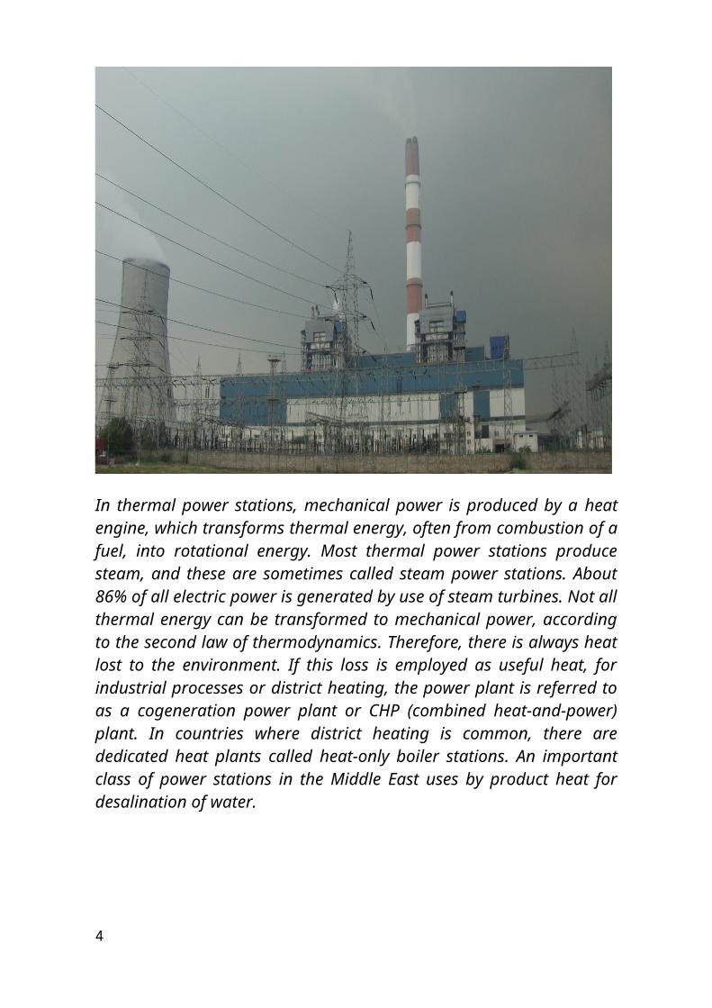
stations in the Middle East uses by product heat for desalination of water.
Thermal power plants are classified by the type of fuel and the type of prime mover installed:-
By fuel Nuclear power plants use a nuclear reactor's heat to operate a steam
turbine generator. Fossil fuelled power plants may also use a steam turbine generator or
in the case of natural gas fired plants may use a combustion turbine. Geothermal power plants use steam extracted from hot underground
rocks. Renewable energy plants may be fuelled by waste from sugar cane,
municipal solid waste, landfill methane, or other forms of biomass. In integrated steel mills, blast furnace exhaust gas is a low-cost,
although low-energy-density, fuel. Waste heat from industrial processes is occasionally concentrated
enough to use for power generation, usually in a steam boiler and turbine.
By prime mover
Steam turbine plants use the dynamic pressure generated by expanding steam to turn the blades of a turbine.
Gas turbine plants use the dynamic pressure from flowing gases to directly operate the turbine. Natural-gas fuelled turbine plants can start rapidly and so are used to supply "peak" energy during periods of high demand, though at higher cost than base-loaded plants.
Combined cycle plants have both a gas turbine fired by natural gas, and a steam boiler and steam turbine which use the exhaust gas from the gas turbine to produce electricity. This greatly increases the overall efficiency of the plant, and most new base load power plants are combined cycle plants fired by natural gas.
Internal combustion Reciprocating engines are used to provide power for isolated communities and are frequently used for small cogeneration plants. Hospitals, office buildings, industrial plants, and other critical facilities also use them to provide backup power in case
4
of a power outage. These are usually fuelled by diesel oil, heavy oil, natural gas and landfill gas.
Micro turbines, Stirling engine and internal combustion reciprocating engines are low cost solutions for using opportunity fuels, such as landfill gas, digester gas from water treatment plants and waste gas from oil production.
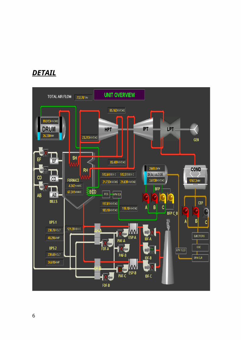
DETAIL
5
OVERVIEW OF UNIT 2 OF PANIPAT THERMAL POWER STATION
Basic Working of Thermal Plant6
Coal from the coal wagons is unloaded in the coal handling plant. This coal is up to the raw coalbunkers with the help of belt conveyers. Coal is transported to the bowl mills by coal feeders. The coal is pulverized in the bowl mill where it is ground to a powder form. The mill consists of a round metallic table on which coal particles fall. This table is rotated with the help of a motor. These are three large rollers, which are spaced 120 degree apart.
When there is no coal, these rollers do not rotate but when coal is fed to the table it packs up between roller and the table and these forces the roller to rotate. Coal is crushed by the crushing action between rollers and the rotating table. This crushed coal is taken away to the furnace through coal pipes with the help of hot and cold air mixture from P.A. fan. This fan takes atmospheric air, a part of which is sent to air pre-heaters for heating while a part goes directly to the mill for temperature control. Atmospheric air from F.D. fan is heated in the air heaters and sent to the furnace as combustion air.
Water from boiler feed pump passes through economizer and reaches the boiler drum. Water from the drum passes through down comers and goes to bottom ring header. Water from the bottom ring header is divided to all the four sides of the furnace. Due to heat and density difference the water rises up in the water wall tubes. Water is partly converted to steam as it rises up in the furnace. This steam and water mixture is again taken to the boilers drum where the steam is separated from the water. Water follows the same path while the steam is sent to super heaters for superheating. The super heaters are located inside the furnace and the steam is superheated (540 deg C) finally it goes to turbine.
A flue gas from the furnace is extracted from the induced draft fan, which maintains balance draft in the furnace with forced draft fans. These flue gases emits their heat energy to various super heaters in the pant house and finally passes through air pre-heaters and goes to electrostatic precipitator where the ash particles are extracted. Electrostatic precipitator consists of metal plates which are electrically charged. Ash particles are attracted on to these plates, so that they do not pass through the chimney, to pollute the atmosphere. A regular mechanical hammer causes the accumulation of ash to fall to the bottom of the precipitator where they are collected in a hopper for disposal. This ash is mixed with water to form slurry and is pumped to ash pond.
The steam from the boiler is conveyed to the turbine through the steam pipes and through stop valve and control valve that automatically regulate the supply of steam to the turbine. Stop valves and control valves are located in a steam chest and governor driven from the main turbine shaft operates the control valves to regulate the amount used.
Steam from the control valves enters the high-pressure cylinder of the turbine, where it passes through the ring of blades fixed to the cylinder wall. These act as nozzles and direct the steam into a second ring of moving blades
7
mounted on the disc secured to the turbine shaft. The second ring turns the shaft as a result of the force of the steam. The stationary and moving blades together constitute a ‘stage’ of a turbine and in practice many stages are necessary, so that the cylinder contains a number of rings of stationary blades with rings of moving blades arranged between them. The steam passes though each stage in turn until it reaches the end of the high-pressure cylinder and in its passage some of its heat energy is changed in to mechanical energy. The steam leaving the high-pressure cylinder goes back to the boiler for reheating and returns by a further pipe to the intermediate pressure cylinder. Here it passes through another series of stationary and moving blades. Finally the steam is taken to the low pressure cylinders, each of which it enters at the centre flowing outwards in the opposite directions through the rows of turbines blades –an arrangement known as double flow-to extremities of the cylinder as the steam gives up its heat energy to drive the turbine its temperature and pressure falls and it expands, because of this expansion the blades are much larger and longer towards the low pressure ends of the turbine.
The turbine shaft usually rotates at 3000rpm.this speed is determined by the frequency of the electrical system used in this country and is the speed at which a 2 pole generator must be driven to generate alternating current at a frequency of 50 cycles /sec. When as much as energy as possible has been extracted from the steam it is exhausted directly to the condenser. This runs the length of the low pressure part of the turbine and may be beneath on either side of it the condenser consist of a large vessel containing some 20000 tubes each about 25mm in diameter cold water from the river, estuary, sea or cooling tower is circulated through these tubes and as the steam from the turbine passes round them it is rapidly condensed into water condensate. Because water has a much smaller comparative volume than steam, a vacuum is created in the condenser. This allows the steam to reduce down to pressure below that of the normal atmosphere and more energy can be utilized.
From the condenser, the condensate is pumped through low-pressure heaters by the extraction pumps after which its pressure is raised to boiler pressure by the boiler feed pump. It is passed through further feed heaters to the economizer and the boiler for the recon version into steam.
A power station generating 2000000 KW of electricity requires about 227500 cubic meter of water an hour for cooling purpose. Here cooling towers are used, about 1/100 part of the cooling water evaporates and a certain amount is returned to its source to carry away any impurities that collects most of it is however recalculated.
8
INTRODUCTION TO JOB ASSIGNED
To study the working project of power generation at THERMAL POWER PLANT,PANIPAT
Diagrammatic Representation of a coal-fired thermal power station
1.Cooling tower 2.Cooling water pump 3. transmission line (3-phase)
4. Step-up transformer (3-phase)
5. Electrical generator (3-phase)
6. Low pressure steam turbine
7. Condensate pump 8. Surface condenser9. Intermediate pressure steam turbine
10. Steam Inlet 11. High pressure steam turbine 12. Deaerator13. Feed water heater 14. Coal conveyor 15. Coal hopper16. Coal pulverizer 17. Boiler steam drum 18. Bottom ash hopper
9
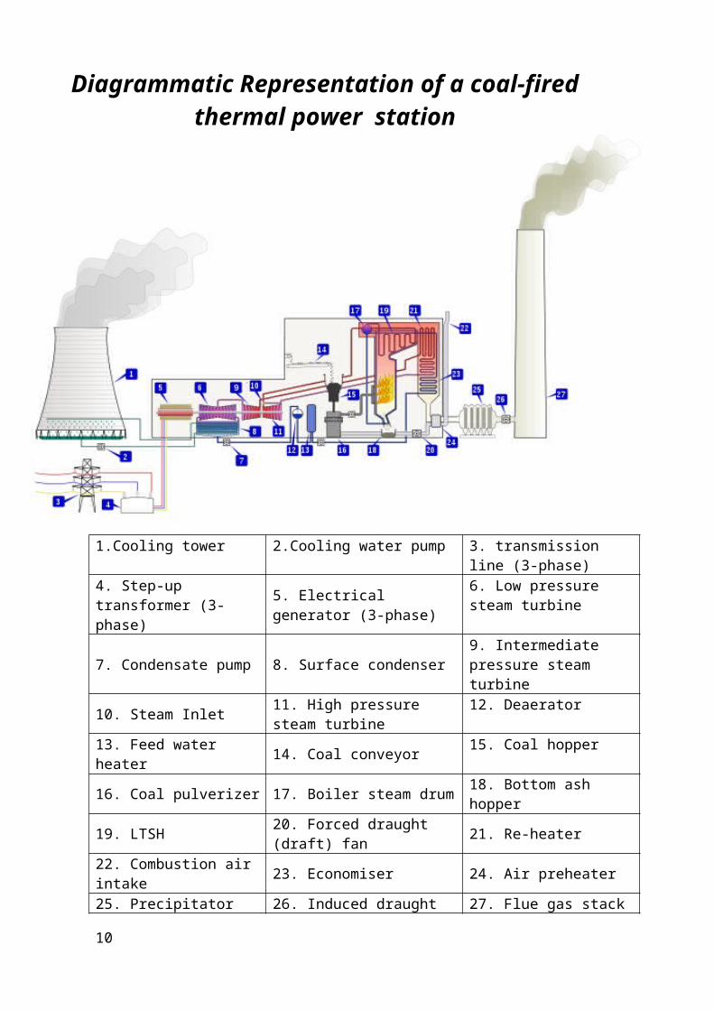
19. LTSH 20. Forced draught (draft) fan 21. Re-heater22. Combustion air intake 23. Economiser 24. Air preheater25. Precipitator (ESP) 26. Induced draught (draft) fan 27. Flue gas stack
10

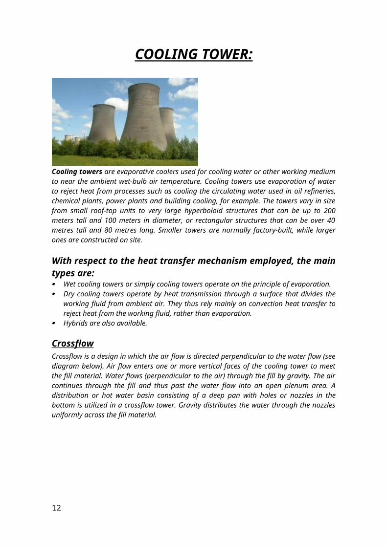
COOLING TOWER:
Cooling towers are evaporative coolers used for cooling water or other working medium to near the ambient wet-bulb air temperature. Cooling towers use evaporation of water to reject heat from processes such as cooling the circulating water used in oil refineries, chemical plants, power plants and building cooling, for example. The towers vary in size from small roof-top units to very large hyperboloid structures that can be up to 200 meters tall and 100 meters in diameter, or rectangular structures that can be over 40 metres tall and 80 metres long. Smaller towers are normally factory-built, while larger ones are constructed on site.
With respect to the heat transfer mechanism employed, the main types are: Wet cooling towers or simply cooling towers operate on the principle of
evaporation. Dry cooling towers operate by heat transmission through a surface that
divides the working fluid from ambient air. They thus rely mainly on convection heat transfer to reject heat from the working fluid, rather than evaporation.
Hybrids are also available.
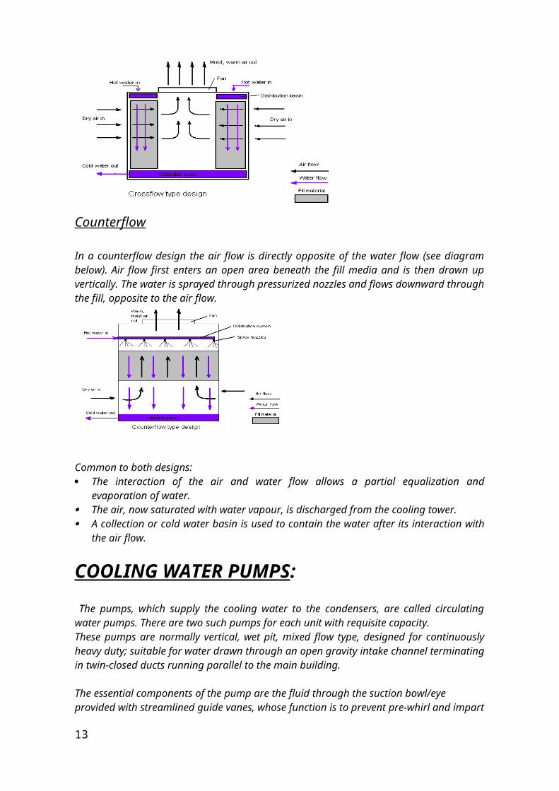
CrossflowCrossflow is a design in which the air flow is directed perpendicular to the water flow (see diagram below). Air flow enters one or more vertical faces of the cooling tower to meet the fill material. Water flows (perpendicular to the air) through the fill by gravity. The air continues through the fill and thus past the water flow into an open plenum area. A distribution or hot water basin consisting of a deep pan with holes or nozzles in the bottom is utilized in a crossflow tower. Gravity distributes the water through the nozzles uniformly across the fill material.
11
Counterflow
In a counterflow design the air flow is directly opposite of the water flow (see diagram below). Air flow first enters an open area beneath the fill media and is then drawn up vertically. The water is sprayed through pressurized nozzles and flows downward through the fill, opposite to the air flow.
Common to both designs: The interaction of the air and water flow allows a partial equalization and
evaporation of water. The air, now saturated with water vapour, is discharged from the cooling
tower. A collection or cold water basin is used to contain the water after its
interaction with the air flow.
COOLING WATER PUMPS:
The pumps, which supply the cooling water to the condensers, are called circulating water pumps. There are two such pumps for each unit with requisite capacity.These pumps are normally vertical, wet pit, mixed flow type, designed for continuously heavy duty; suitable for water drawn through an open gravity intake channel terminating in twin-closed ducts running parallel to the main building.
The essential components of the pump are the fluid through the suction bowl/eye provided with streamlined guide vanes, whose function is to prevent pre-whirl and impart hydraulically correct flow to the liquid. The propeller, in
12
turn imparts motion to the fluid. The purpose of the discharge bowl, provided with streamlined diffuser vanes, is to direct the flow of water into the discharge column.
TRANSFORMERS:The transformer is the most convenient and economical device for transfer of power from one voltage to another voltage at the same frequency. It works on the principle of electromagnetic induction. There is hardly any installation without a transformer. Due to this equipment, it has been possible to transmit bulk power to load centres from far off power houses and to various machineries and switchgears of the power plants.
TRANSFORMERS ARE OF TWO TYPES:-
#STEP-UP TRANSFORMER- which step-up the voltage at secondary side called as step- up transformer.
#STEP-DOWN TRNSFORMER- which step-down the voltage at secondary side called as step- down transformer.
MAIN PARTS OF POWER TRANSFORMERS
# PRIMARY WINDING# SECONDRY WINDING# OIL TANK# DRAIN COKE# CONSERVATOR# BRETHER# TUBES FOR COOLING # TRNSFORMER OIL# EARTH POINT# EXPLOSION VENT# TEMPERATURE GAUGE# BUCHHOLZ RELAY# PRIMARY TERMINALS# SECONDARY TERMINALS
ACCESSORIES OF TRANSFORMERS
1. OIL CONSERVATOR:-Oil conservator is a short of dum mounted on the top of transformer. A level indicator is fixed to it, which gives alarm to low level. Conservator is connected through a pipe to the transformer tank containing oil. This oil expands and contract depending upon the heat produced and so the oil level conservator is left open to the atmosphere through a breather so that the extra air may go out or come in.
2. BREATHER:-
13
The breather is a box containing calcium chloride or silica gel to absorb moisture of our entering the conservator as it is well known fact that the insulating property of the transformers oil is lost if a small amount of moisture enter in it. So dry air is allowed to pass through the breather. When oil level in oil conservator changes, air moes in & out of the conservator. This action is known as breathing. Dry silica gel is of the blue colour. It turns pale pink as it absorbs moisture. The wet silica gel can be regenerated by drying.
3. BUCHHOLZ RELAY:-This relay is a gas-actuated relay which is meant for the protecting of oil immersed transformer from insulation failure, core heating or any type of internal fault which may cause the heating of oil beyond the specified temp. Due to any internal fault, oil is heated –up & oil vapour so formed causes either the alarm circuit(for less fault) or trip the circuit(for sever fault).
4. EXPLOSION VENT:-It is also a safety device of the transformer which protects the transformer tank from gases induced by & any type of short circuit in the transformer. This consists of a vertical pipe closed by a diaphragm made of thin bakelite sheet. This diaphragm burst or slides out in case of abnormal pressure inside the tank. A diverter plate is used at the bottom of the explosion vent to ensure that gases produce inside the transformer are directed toward the buchholz relay & don’t get collected inside the ventilation and equalise the pressure on each side of the diverter plate.
5. TEMP. INDICATOR:-It is also a protective device fitted to the transformer to indicate temp. of transformer oil. For measuring temp. Of the oil, bulb of the vapour pressure type thermometer is placed in the hot oil & dial of the thermometer is mounted outside the tank. Two indicating pointers black and red are provided. Alarm contacts are also provided which come into action when predetermined permissible higher temperature is reached under abnormal operating conditions.
6. BUSHING: –The bushing serves as supports and insulation of the bus bars and transformer terminal. The bushing consists of porcelain shell body, upper and lower locating washer used for fixing the position of bush bar and mounting flange with the hole drilled for fixing bolt and it is supplied with an earthing bolt.
7. MAGANETIC OIL GAUGE:-The magnetic oil level gauge supervises the level of oil in the conservator tank. The oil level gauge is provided on the transformer are of dial type with minimum and maximum level marking and a pointer which indicate the level of oil in the conservator. Sometime the scale is also graduated for oil temperature on the basis of its level.
8. TAP CHANGER:–The voltage control of transmission and distribution systems is obtained by tap changer. Tap changer are either on load or off load tap changer. Tap changer is fitted with the transformer for adjusting secondary voltage.
14
IMPORTANT TRANSFORMERS IN THE PLANT
1. GENERATOR TRANSFORMER (240 MVA, 11 KV/220KV) It converts 11kv which is supplied from generator 220kv and supplied it to the bus bar/ grid.
2. STATION SERVICE TRANSFORMER (40MVA, 220KV/6.6KV)It converts 220kv which is coming to station from bbmb to 6.6kv and fed to station auxiliary.
3. UNIT AUXILIARY TRANSFORMER (15MVA, 11KV/6.6KV) It converts 11kv which is supplied from generator to 6.6kv to fed unit auxiliary.
110 MW TURBO GENERATOR
GENERAL:-
Modern features of direct cooling by water & hydrogen are incorporated in the 250 MW turbo generators thus evolves an economical & reliable design. The machine is provided with a fast acting excitation system & dependable auxiliary service to give prolonged trouble free operation over the years. All the material that goes into the manufacture of this machine subjected to various test as per national & international standards. Each component undergoes series of stage wise tests. The generator, 30 ft (9 m) long and 12 ft (3.7 m) diameter, contains a stationary stator and a spinning rotor, each containing miles of heavy copper conductor—no permanent magnets here. In operation it generates up to 21,000 amps at 16.5kV AC 110(MW) as it spins at either 3,000 RPM, synchronized to the power grid. The rotor spins in a sealed chamber cooled with hydrogen gas, selected because it has the highest known heat transfer coefficient of any gas and for its low viscosity which reduces windage losses. This system requires special handling during start up, with air in the chamber first displaced by carbon dioxide before filling with hydrogen. This ensures that the highly flammable hydrogen does not mix with oxygen in the air.The electricity flows to a distribution yard where transformers step the voltage up to 115, 230, 500 or 765 kV AC as needed for transmission to its destination.
Description of various parts is given below:-
1.STATOR WINDING AND INSULATION:-
The stator has a three phase, double layer, short chorded, bar type winding, having two parallel pats. Each coil side consists of glass insulated solid and
15
hollow conductors with cooling water passing through the patter. The elementary conductors are roebel transposed in the slot poetion of winding to minimize eddy current losses.Adequate protection is provided to avoid corona & other discharges. In the slots, the sides are firmly held in the position by fiborousslot wages, which are mechanically strong and have high dielectric properties. The overhang portion of the coil is securely lashed with glass chord to bondage rings & special breckets of non magnetic steel, which are in turn, fixed to the core press rings. On short circuits the forces between the conductor tend to open the cone formed by overhang portion of the coils , but the movement is effectively presented by supports & lashings.
2. DISTILLATE HEADERS OR STATOR WATER HEADER:-
Ring type water headers, made of copper are provided separately for distillate inlet & outlet in the stator on turbine side. The headers are supported on insulators and isolated from stator body. The winding ends are soledly soldered into the coil lugs which are than ultrasonically tested. Individual bars are provided with water inlet/outlet connections made of p.t.f.e. houses. The bar heads are insulated by fiber moulded corners. The winding scheme along with the water connections. The complete water path assembly is subjected to the rigid hydroatic pneumatic tests at various stages to ensure water tightness and to detect blocking of the flows paths.3. TERMINAL BUSHINGS :-
Water cooled terminal bushings are housed in the lower part of the stator on the slip ring side. Porcelain insulators are provided to insulate the terminal bars from the stator body. Effective sealing is provided between the terminal bushing and the statir bidy to avoid any possibility of leakage of hydrogen. Terminal bushing is housed inside a chamber made of non magnetic steel plates. Three phase terminals are brought out to facilitate external connections. The terminal plate of the end terminals, where bus bar connections are made is silver plated.The terminal bushings can be replaced without removing the stator from foundation. Provision is made for fixing the external bus ducts with the terminal plate.
4. ROTOR:-
The rotor is of cylindrical type shaft and body being forged in one piece from chromium, nickel, molybdenum & vanadium steel. Prior to matching, a series of comprehensive ultrasonic examination and other tests are carried out on rotor body and shaft portion to ensure of any internal defects. The rotor with all the details assembled, dynamically balanced to a high degree of accuracy and subjected to 20% over speeding for 2 minutes ensuring mechanical strength.
5. FIELD WINDING:-
The field winding is made from hard drawn silver bearing Copper. Rotor winding is held in position against centrifugal forces by dualism forces wedges in the slot portion & by non magnetic steel retaining rings in the over hang portion. Gap pick up system is employed for direct hydrogen cooling of
16
rotor winding. Several groups of ventilation ducts are mulled on the sides of the rotor coil for gas passage. The rotor slot wedges are of special profiles with elliptical holes rolled in to match the ventilation ducts on the winding stacks. The end windings are insulated from rings with the help of glass epoxy moulded segments. Copper segmental type damper winding is provided in the end zone of rotor mordws to prevent over heating of returning ring s during asymmetrical & asynchronous operation.
6. SHAFT MOUNTED FANS:-
For circulating the cooling gas inside the generator, two propeller type fans are shaft mounted on this & of rotor body. Fan hubs are made from alloy steel forging and are hot fitted on the rotor shaft with sufficient interference. The alloy steel cast fan blades are machined in the tail portion to suit the fan hub and held in position with the help of conical pins. The blades can be easily removed from or assembled in the fan hub. Fan shields fixed to the end shields, guide the flow of gas through the fan sections.
7.SLIP RINGS:-
The slip ring consists of helically grooved alloy steel rings shrunk on the rotor shaft & insulated from it. For convenience in assembly both the rings are mounted on a single, common steel bush, which has an insulated jacket pre moulded on it. The complete bush with slip ring is shrunk on the rotor shafts. The slip rings are provided with inclined holes for self-ventilation. The helical grooves cut on the outer surface of the slip rings improves brush performance.
Turbine
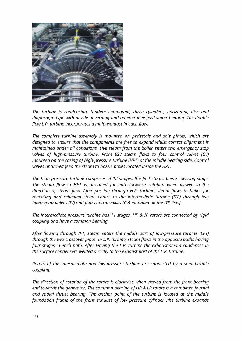
The turbine is condensing, tandem compound, three cylinders, horizontal, disc and diaphragm type with nozzle governing and regenerative feed water heating. The double flow L.P. turbine incorporates a multi-exhaust in each flow.
17
The complete turbine assembly is mounted on pedestals and sole plates, which are designed to ensure that the components are free to expand whilst correct alignment is maintained under all conditions. Live steam from the boiler enters two emergency stop valves of high-pressure turbine. From ESV steam flows to four control valves (CV) mounted on the casing of high-pressure turbine (HPT) at the middle bearing side. Control valves unturned feed the steam to nozzle boxes located inside the HPT.
The high pressure turbine comprises of 12 stages, the first stages being covering stage. The steam flow in HPT is designed for anti-clockwise rotation when viewed in the direction of steam flow. After passing through H.P. turbine, steam flows to boiler for reheating and reheated steam comes to the intermediate turbine (ITP) through two interceptor valves (IV) and four control valves (CV) mounted on the ITP itself.
The intermediate pressure turbine has 11 stages .HP & IP rotors are connected by rigid coupling and have a common bearing.
After flowing through IPT, steam enters the middle part of low-pressure turbine (LPT) through the two crossover pipes. In L.P. turbine, steam flows in the opposite paths having four stages in each path. After leaving the L.P. turbine the exhaust steam condenses in the surface condensers welded directly to the exhaust part of the L.P. turbine.
Rotors of the intermediate and low-pressure turbine are connected by a semi-flexible coupling.
The direction of rotation of the rotors is clockwise when viewed from the front bearing end towards the generator. The common bearing of HP & LP rotors is a combined journal and radial thrust bearing. The anchor point of the turbine is located at the middle foundation frame of the front exhaust of low pressure cylinder .the turbine expands towards the front bearing by nearly 32mm and towards the generator by 3mm in steady state operation at full load with rated parameters.
Turbine is equipped with a barring gear which rotates the rotor of the turbine at a speed of nearly 3.4. Rpm for providing uniform heating during starting and uniform cooling during shut down.In order to heat the feed water in the regenerative cycle of the turbine, condensate from the hot well of condenser pumps, and supplied to the deaerator through ejectors, gland cooler from deaerator the feed water is supplied to boiler by boiler feed pumps through the H.P. heaters. Extracted steam from the various points of the turbine is utilized to heat the condensate in these heat exchangers.
High-pressure rotor: the H.P. rotor is machined from single Cr-Mo-V steel forging with internal discs. The rotor forging is thermally stabilized to prevent abnormal deflection. The blades are attached to their respective wheels by ‘T’ root fastening. In all the moving wheels, balancing holes are machined to reduce the pressure difference across them, which result in reduction of axial thrust.
Intermediate pressure rotor: the I.P. rotor has seven disc integrally forged with rotor while last four discs are shrunk fit. The shaft is made of high creep resisting Cr-Mo-V
18
Steel forgings while the shrunk fit is machined from high strength nickel steel forgings. The blades on the integral disc are secured by ‘T’ root fastenings while on shrunk fit disc by ‘fork root’ fastening. Except the last two wheels, all other wheels have surroundings riveted at tip of the blades. To adjust the frequency of the moving blades, lashing wires have been provided in some stages.
Low pressure rotor: The L.P. rotors consist of shrunk fit discs on the shaft. The shaft is steel forging of Cr-Mo-V steel while the disc is of high strength a nickel steel forging. Blades are secured to the respective discs by riveted fork root fastening. In all the stages lashing wires are provided to adjust the frequency of the blades. In the last two rows satellite strips are provided at the leading edges of the blades to protect them against wet steam erosion.
CONDENSATE PUMPS: The function of these pumps is to pump out the condensate to the deaerator through ejectors, gland steam cooler, and L.P. heaters. These pumps have four stages and since the suction is at a negative pressure, special arrangements have been made for providing sealing. These are rated generally for 160cu.m.hr. Flow at a pressure 13.2 kg/cm.sq.
GLAND STEAM COOLER: Steam from deaerator or from auxiliary steam header is supplied to the end seals of the H.P, rotor and L.P. rotor generally at a pressure of 1.01 to 1.03 atm. Abs. So as to prevent ingress of atmospheric air in the turbine through the end clearances. This steam supplied to the end seals is extracted by the gland steam cooler by the action of single stage steam ejector.
Condenser:
Diagram of a typical water-cooled surface condenser
19
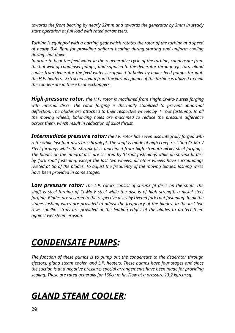
The surface condenser is a shell and tube heat exchanger in which cooling water is circulated through the tubes. The exhaust steam from the low pressure turbine enters the shell where it is cooled and converted to condensate (water) by flowing over the tubes as shown in the adjacent diagram. Such condensers use steam ejectors or rotary motor-driven exhausters for continuous removal of air and gases from the steam side to maintain vacuum.
For best efficiency, the temperature in the condenser must be kept as low as practical in order to achieve the lowest possible pressure in the condensing steam. Since the condenser temperature can almost always be kept significantly below 100 oC where the vapor pressure of water is much less than atmospheric pressure, the condenser generally works under vacuum. Thus leaks of non-condensable air into the closed loop must be prevented. Plants operating in hot climates may have to reduce output if their source of condenser cooling water becomes warmer; unfortunately this usually coincides with periods of high electrical demand for air conditioning.
The condenser generally uses either circulating cooling water from a cooling tower to reject waste heat to the atmosphere, or once-through water from a river, lake or ocean.
EJECTORS:
There are two 100% capacity ejectors of the steam eject type. The purpose of the ejector is to evacuate air and other non condensing gases from the condensers. The ejector used in the plant, is a 3-stage ejector using steam from the deaerator with 11 at header as the working medium. The ejector has three has three compartments. Steam is supplied generally at a pressure of 4.5 to 5 kg/esq. to the three nozzles in the three compartments. Steam expands in the nozzle thus giving a high velocity eject which creates a low pressure in the throat of the ejector. Since the nozzle box of the ejector is connected to eh air pipe from the condenser, the air and pressure zone. The working steam which has expanded in volume comes in contact with the cluster of tube bundles through which condensate is flowing and gets condensed thus further aiding the formation of vacuum. The non condensing gases of air are further sucked with the next stage of the ejector by the action of the second nozzle. The process repeats itself in the third stage also and finally the steam air mixture is exhausted into the atmosphere through the outlet.
EMERGENCY STOP VALVES AND CONTROL VALVES:
Turbine is equipped with emergency stop valves to cut off steam supply and with control valves to regulate steam supply. Emergency stop valves are provided in the main steam line and the interceptor valves are provided in the hot reheat line.
Emergency stop valves are actuated by servomotor controlled by the protection system. ESV remains either fully open or fully closed.
20
Control valves are actuated by the governing system through servomotors to regulate steam supply as required by the load.Valves are either single seat type or double seat type. Single seat type is preferred though these require higher force for opening or closing.
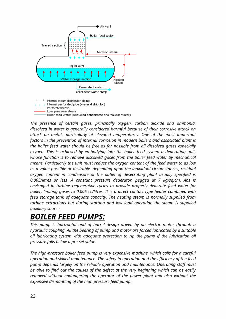
DEAERATOR:
The presence of certain gases, principally oxygen, carbon dioxide and ammonia, dissolved in water is generally considered harmful because of their corrosive attack on attack on metals particularly at elevated temperatures. One of the most important factors in the prevention of internal corrosion in modern boilers and associated plant is the boiler feed water should be free as far possible from all dissolved gases especially oxygen. This is achieved by embodying into the boiler feed system a deaerating unit, whose function is to remove dissolved gases from the boiler feed water by mechanical means. Particularly the unit must reduce the oxygen content of the feed water to as low as a value possible or desirable, depending upon the individual circumstances, residual oxygen content in condensate at the outlet of desecrating plant usually specified is 0.005/litres or less .A constant pressure deaerator, pegged at 7 kg/sq.cm. Abs is envisaged in turbine regenerative cycles to provide properly deaerate feed water for boiler, limiting gases to 0.005 cc/litres. It is a direct contact type heater combined with feed storage tank of adequate capacity. The heating steam is normally supplied from turbine extractions but during starting and low load operation the steam is supplied auxiliary source.
BOILER FEED PUMPS:
This pump is horizontal and of barrel design driven by an electric motor through a hydraulic coupling. All the bearing of pump and motor are forced lubricated by a suitable oil lubricating system with adequate protection to rip the pump if the lubrication oil pressure falls below a pre-set value.
21
The high-pressure boiler feed pump is very expensive machine, which calls for a careful operation and skilled maintenance. The safety in operation and the efficiency of the feed pump depends largely on the reliable operation and maintenance. Operating staff must be able to find out the causes of the defect at the very beginning which can be easily removed without endangering the operator of the power plant and also without the expensive dismantling of the high pressure feed pump.
The feed pump consist of a barrel, into which is mounted the inside stator together with the rotor. The hydraulic part is enclosed by the high-pressure cover behind the balancing device. The suction side of the barrel and the space in the high-pressure cover behind the balancing device are enclosed by the low-pressure covers along with the stuffing box casings. The brackets of the radial bearing of the suction side and radial and thrust bearing of the discharge side are fixed to the low pressure covers. The entire pumps are mounted on a foundation frame. The hydraulic coupling and two claw couplings with coupling guards are also delivered along with the pump. Water cooling and oil lubricating connections are provided with their accessories.
FEED WATER HEATER:
LOW PRESSURE HEATERS: Turbine has been provided with non-controlled extractions, which are utilized for heating the condensate, from turbine-bled steam. There are 4 low pressure heaters in which the last four extractions are used. L.P. Heater-1 has two parts LHP-1A and LHP-1B located in the upper parts of the condenser A and condenser B respectively. These are horizontal type shell and tube construction. L.P.H 2, 3 are of similar construction and they are mounted in a row at 5m level. They are of vertical construction with brass tubes the ends of which are expanded into the tube plate. These are equipped with necessary safety valves in the steam space level indicator for visual level indication of heating steam condensate pressure vacuum gauges for measurement of steam pressure etc.
HIGH PRESSURE HEATERS:
These are regenerative feed water heaters operating at high pressure and located by the side of turbine. These are generally vertical type and turbine bled steam pipes are connected to them.HP heaters are connected in series on feed waterside and by such arrangement, the feed water, after feed pump enters the HP heaters. The steam is supplied to these heaters from the bled point of the turbine through motor operated valves. These heaters have a group bypass protection on the feed water side. In the event of tube rupture in any of the HPH and the level of the condensate rising to dangerous level, the group protection diverts automatically the feed water directly to boiler, thus bypassing all the `3` H.P. heaters.
22
FUEL TRANSPORT AND DELIVERY:Coal is delivered by mass transport systems, truck, rail, barge or collier. A large coal train called a "unit train" may be two kilometres long, containing 100 cars with 100 tons of coal in each one, for a total load of 10,000 tons. A large plant under full load requires at least one coal delivery this size every day. Plants may get as many as three to five trains a day, especially in "peak season", during the summer months when power consumption is high. Modern unloaders use rotary dump devices, which eliminate problems with coal freezing in bottom dump cars. The unloader includes a train positioner arm that pulls the entire train to position each car over a coal hopper. The dumper clamps an individual car against a platform that swivels the car upside down to dump the coal. Swivelling couplers enable the entire operation to occur while the cars are still coupled together. Unloading a unit train takes about three hours. A large thermal power plant such as the one at Nanticoke Ontario stores several million tons of coal for winter use when the lakes are frozen.Shorter trains may use railcars with an "air-dump", which relies on air pressure from the engine plus a "hot shoe" on each car. This "hot shoe" when it comes into contact with a "hot rail" at the unloading trestle, shoots an electric charge through the air dump apparatus and causes the doors on the bottom of the car to open, dumping the coal through the opening in the trestle. Unloading one of these trains takes anywhere from an hour to an hour and a half. Older unloaders may still use manually operated bottom-dump rail cars and a "shaker" attached to dump the coal. Generating stations adjacent to a mine may receive coal by conveyor belt or massive diesel-electric-drive trucks.A collier (cargo ship carrying coal) may hold 40,000 tons of coal and takes several days to unload. Some colliers carry their own conveying equipment to unload their own bunkers; others depend on equipment at the plant. Colliers are large, seaworthy, self-powered ships. For transporting coal in calmer waters, such as rivers and lakes, flat-bottomed vessels called barges are often used. Barges are usually unpowered and must be moved by tugboats or towboats.For start up or auxiliary purposes, the plant may use fuel oil as well. Fuel oil can be delivered to plants by pipeline, tanker, tank car or truck. Oil is stored in vertical cylindrical steel tanks as large as 90,000 barrels (14,000 m³). The heavier no. 5 "bunker" and no. 6 fuels are steam-heated before pumping in cold climates.Plants fuelled by natural gas are usually built adjacent to gas transport pipelines or have dedicated gas pipelines extended to them.
Fuel processing: Coal is prepared for use by crushing the rough coal to pieces less than 2 inches (50 mm) in size. The coal is transported from the storage yard to in-plant storage silos by rubberized conveyer belts at rates up to 4,000 tons per
23
hour. A 400 ton silo may feed each coal pulverizer (coal mill) at a rate of up to 60 tons per hour. Coal fed into the top of the pulverizer and ground to a powder, the consistency of face powder, is blown, with air, into the furnace. A 500 MW plant will have three such pulverizers, two of which can supply coal to the furnace at 250 tons per hour under full load.
BOILER:
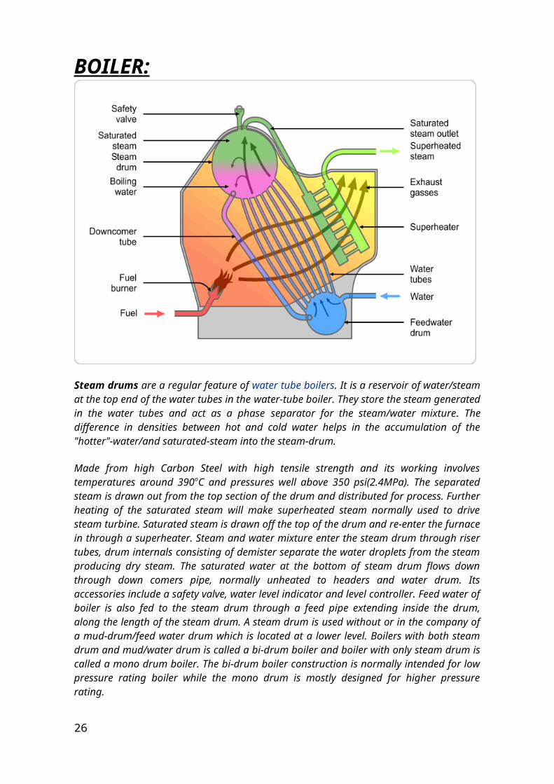
Steam drums are a regular feature of water tube boilers. It is a reservoir of water/steam at the top end of the water tubes in the water-tube boiler. They store the steam generated in the water tubes and act as a phase separator for the steam/water mixture. The difference in densities between hot and cold water helps in the accumulation of the "hotter"-water/and saturated-steam into the steam-drum.
Made from high Carbon Steel with high tensile strength and its working involves temperatures around 390oC and pressures well above 350 psi(2.4MPa). The separated steam is drawn out from the top section of the drum and distributed for process. Further heating of the saturated steam will make superheated steam normally used to drive steam turbine. Saturated steam is drawn off the top of the drum and re-enter the furnace in through a superheater. Steam and water mixture enter the steam drum through riser tubes, drum internals consisting of demister separate the water droplets from the steam producing dry steam. The saturated water at the bottom of steam drum flows down through down comers pipe, normally unheated to headers and water drum. Its accessories include a safety valve, water level indicator and level controller. Feed water of boiler is also fed to the steam drum through a feed pipe extending inside the drum, along the length of the steam
24
drum. A steam drum is used without or in the company of a mud-drum/feed water drum which is located at a lower level. Boilers with both steam drum and mud/water drum is called a bi-drum boiler and boiler with only steam drum is called a mono drum boiler. The bi-drum boiler construction is normally intended for low pressure rating boiler while the mono drum is mostly designed for higher pressure rating.
SUPER HEATER:
FROM TO H.P.TURBINEBOILER
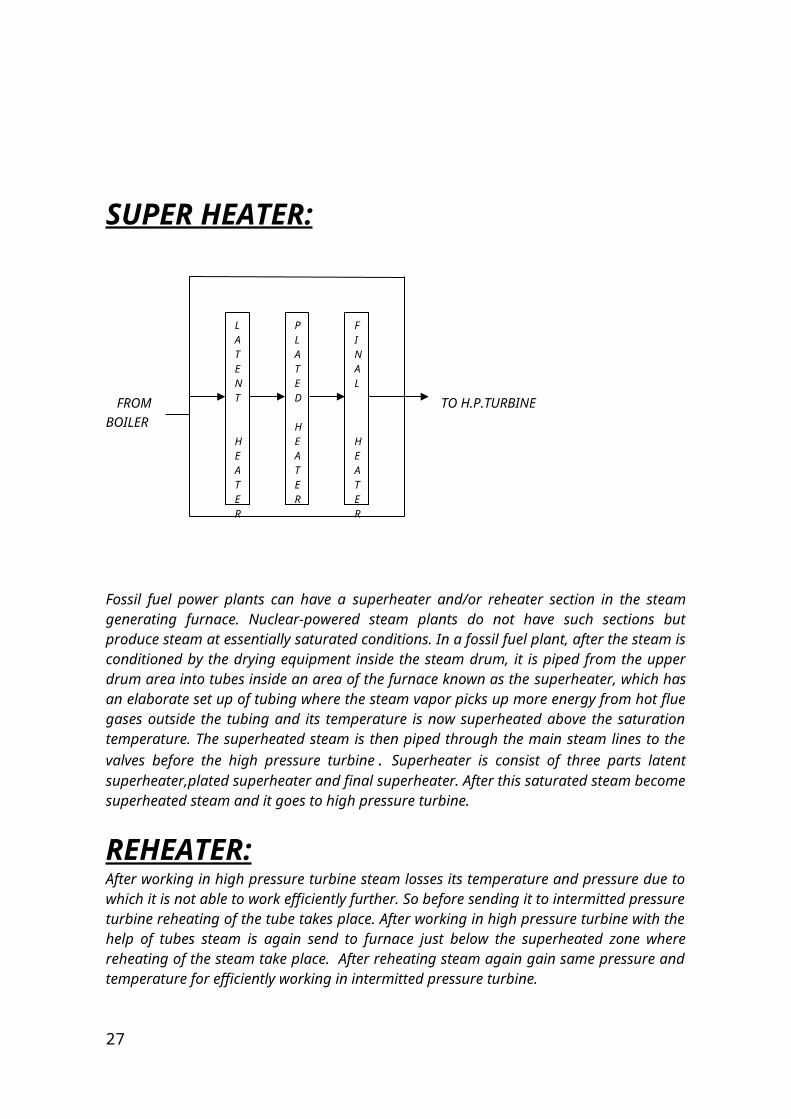
Fossil fuel power plants can have a superheater and/or reheater section in the steam generating furnace. Nuclear-powered steam plants do not have such sections but produce steam at essentially saturated conditions. In a fossil fuel plant, after the steam is conditioned by the drying equipment inside the steam drum, it is piped from the upper drum area into tubes inside an area of the furnace known as the superheater, which has an elaborate set up of tubing where the steam vapor picks up more energy from hot flue gases outside the tubing and its temperature is now superheated above the saturation temperature. The superheated steam is then piped through the main steam lines to the valves before the high pressure turbine. Superheater is consist of three parts latent superheater,plated superheater and final superheater. After this saturated steam become superheated steam and it goes to high pressure turbine.
REHEATER:After working in high pressure turbine steam losses its temperature and pressure due to which it is not able to work efficiently further. So before sending it to intermitted pressure turbine reheating of the tube takes place. After working in high pressure turbine with the help of tubes steam is again send to furnace just below the superheated zone where reheating of the
25
LATENT
HEATER
PLATED HEATER
FINAL
HEATER
steam take place. After reheating steam again gain same pressure and temperature for efficiently working in intermitted pressure turbine.
Economizers : In Economizer we use the flue gases for the preheating of the boiler feed water. In boilers, economizers are heat exchange devices that heat fluids, usually water, up to but not normally beyond the boiling point of that fluid. Economizers are so named because they can make use of the enthalpy in fluid streams that are hot, but not hot enough to be used in a boiler, thereby recovering more useful enthalpy and improving the boiler's efficiency. They are a device fitted to a boiler which saves energy by using the exhaust gases from the boiler to preheat the cold water used the fill it
ELECTROSTATIC PRECIPITATOR: The electrostatic precipitators are extensively used in removal of fly ash from electric utility boiler emissions. The use of this collector is growing rapidly because of the new strict air quality codes. An electrostatic precipitator can be designed to run at any desired efficiency for use as a primary collector or as a supplementary unit to a cyclone collector. It is often considered worthwhile to retain an existing cyclone as a primary collector in cases where collection efficiencies must be upgraded especially where there is large amount of unburnt carbon in fly ash( about 15%) because the presence of large quantities of carbon in the gas can adversely affect the collection efficiency of a precipitator.
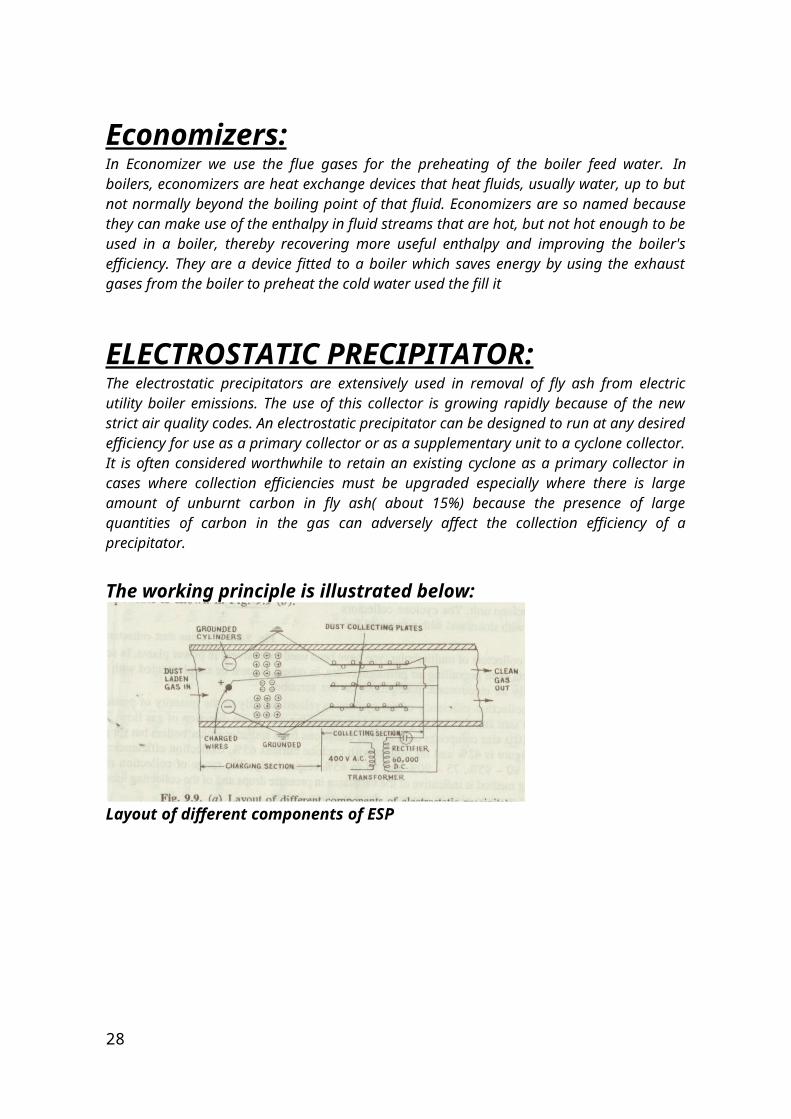
The working principle is illustrated below:
Layout of different components of ESP
26
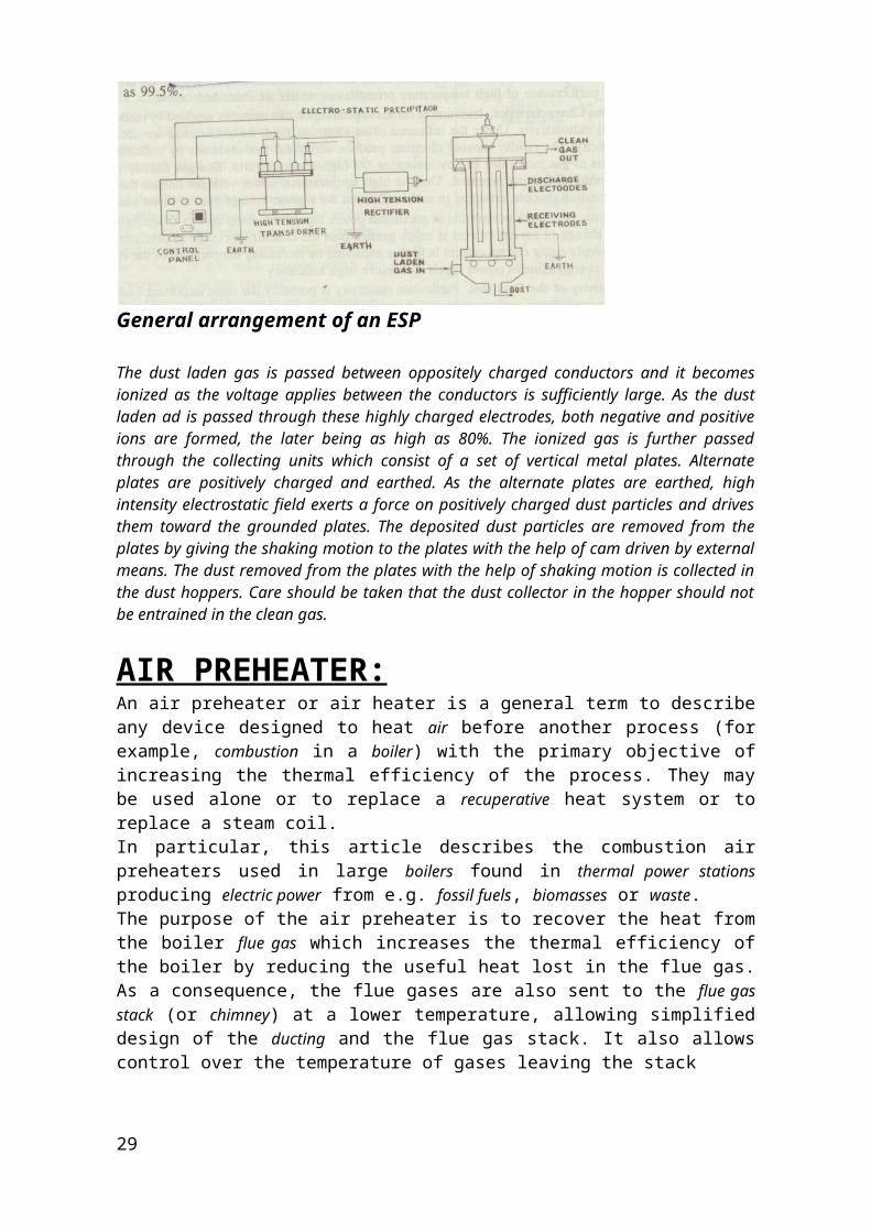
General arrangement of an ESP
The dust laden gas is passed between oppositely charged conductors and it becomes ionized as the voltage applies between the conductors is sufficiently large. As the dust laden ad is passed through these highly charged electrodes, both negative and positive ions are formed, the later being as high as 80%. The ionized gas is further passed through the collecting units which consist of a set of vertical metal plates. Alternate plates are positively charged and earthed. As the alternate plates are earthed, high intensity electrostatic field exerts a force on positively charged dust particles and drives them toward the grounded plates. The deposited dust particles are removed from the plates by giving the shaking motion to the plates with the help of cam driven by external means. The dust removed from the plates with the help of shaking motion is collected in the dust hoppers. Care should be taken that the dust collector in the hopper should not be entrained in the clean gas.
AIR PREHEATER:An air preheater or air heater is a general term to describe any device designed to heat air before another process (for example, combustion in a boiler) with the primary objective of increasing the thermal efficiency of the process. They may be used alone or to replace a recuperative heat system or to replace a steam coil.In particular, this article describes the combustion air preheaters used in large boilers found in thermal power stations producing electric power from e.g. fossil fuels, biomasses or waste. The purpose of the air preheater is to recover the heat from the boiler flue gas which increases the thermal efficiency of the boiler by reducing the useful heat lost in the flue gas. As a consequence, the flue gases are also sent to the flue gas stack (or chimney) at a lower temperature, allowing simplified design of the ducting and the flue gas stack. It also allows control over the temperature of gases leaving the stack
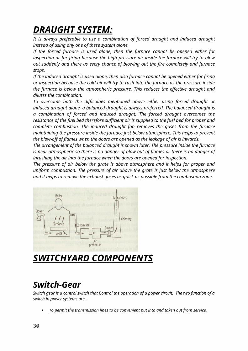
DRAUGHT SYSTEM:It is always preferable to use a combination of forced draught and induced draught instead of using any one of these system alone.If the forced furnace is used alone, then the furnace cannot be opened either for inspection or for firing because the high pressure air inside the furnace will try to blow out suddenly and there us every chance of blowing out the fire completely and furnace stops.
27
If the induced draught is used alone, then also furnace cannot be opened either for firing or inspection because the cold air will try to rush into the furnace as the pressure inside the furnace is below the atmospheric pressure. This reduces the effective draught and dilutes the combination.To overcome both the difficulties mentioned above either using forced draught or induced draught alone, a balanced draught is always preferred. The balanced draught is a combination of forced and induced draught. The forced draught overcomes the resistance of the fuel bed therefore sufficient air is supplied to the fuel bed for proper and complete combustion. The induced draught fan removes the gases from the furnace maintaining the pressure inside the furnace just below atmosphere. This helps to prevent the blow-off of flames when the doors are opened as the leakage of air is inwards.The arrangement of the balanced draught is shown later. The pressure inside the furnace is near atmospheric so there is no danger of blow out of flames or there is no danger of inrushing the air into the furnace when the doors are opened for inspection.The pressure of air below the grate is above atmosphere and it helps for proper and uniform combustion. The pressure of air above the grate is just below the atmosphere and it helps to remove the exhaust gases as quick as possible from the combustion zone.
SWITCHYARD COMPONENTS
Switch-GearSwitch gear is a control switch that Control the operation of a power circuit. The two function of a switch in power systems are –
To permit the transmission lines to be convenient put into and taken out from service.
To disable the some plant and lines when these become faulty, to be rapidly and safely isolated by automatic means.
The first of these can be served by relatively simple switches the second however require circuit breakers, which are more robust & capable of breaking the large value of fault power that results in faults on major power system. Since all plants and lines are liable to develop faults as a results of mechanical damage, electrical breakdown, errors in operation etc. The simple isolators switch in favour of automatic circuit breakers even for switching function.
The whole switchgear assembly consists of two parts:-
28
Panel Panel consists of protective relays, mounting of potential transformer, current transformer, ammeter, voltmeter & energy meter. The potential transformer is mounted on the panel. The primary is connected to 11kv & the reduce voltage from the secondary is given to energy meter as line voltages & for protective purposes.
Trolly The trolly consists of current carrying contacts called electrodes. These are normally engaged but in predetermined conditions, separate to interrupt the circuit, when the contacts are made.
Bus bar arrangementConductors to which a number of circuits are connected called bus – bars. In power plants, shut down results disconnection of supply to a large area. Hence to avoid shut down the major plants should have elaborate bus bar arrangement with duplicate buses, alternative supply arrangement section etc. The extra high voltage equipments such as isolators, circuit breaker are generally costly hence unnecessary equipment should not be provided.
Single bus bar arrangement:-The single arrangement consists of a single (three phase) bus bar to which various feeders are connected. In case of fault or maintenance of bus, the entire bus bar has to be de-energised and the total shutdown results. This scheme is most economical and simple.
Double bus bar arrangement:-The double bus systems provide additional flexibility, continuity of supply and permit periodic maintenance. In the event of fault on the bus bar the other can be used the figure shows to the bus bar arrangement. There are two buses called main bus and reserve bus. The coupler can be closed so as to connect two buses while transferring the power to the reserve bus.
Closed bus coupler, the two buses are now at same potential. Closed isolator on reserve bus.Open isolator on main bus.
Protective relay:A protective relay is a complex electromechanical apparatus, often with more than one coil, designed to calculate operating conditions on an electrical circuit and trip circuit breakers when a fault was found. Unlike switching type relays with fixed and usually ill-defined operating voltage thresholds and operating times, protective relays had well-established, selectable, time/current (or other operating parameter) curves. Such relays were very elaborate, using arrays of induction disks, shaded-pole magnets, operating and restraint coils, solenoid-type operators, telephone-relay style contacts, and phase-shifting networks to allow the relay to respond to such conditions as over-current, over-voltage, reverse power flow, over- and under- frequency, and even distance relays that would trip for faults up to a certain distance away from a substation but not beyond that point. An important transmission line or generator unit would have had cubicles dedicated to protection, with a score of individual electromechanical devices. 29
The various protective functions available on a given relay are denoted by standard ANSI Device Numbers. For example, a relay including function 51 would be a timed over current protective relay.
These protective relays provide various types of electrical protection by detecting abnormal conditions and isolating them from the rest of the electrical system by circuit breaker operation. Such relays may be located at the service entrance or at major load centers.
Design and theory of these protective devices is an important part of the education of an electrical engineer who specializes in power systems. Today these devices are nearly entirely replaced (in new designs) with microprocessor-based instruments (numerical relays) that emulate their electromechanical ancestors with great precision and convenience in application. By combining several functions in one case, numerical relays also save capital cost and maintenance cost over electromechanical relays. However, due to their very long life span, tens of thousands of these "silent sentinels" are still protecting transmission lines and electrical apparatus all over the world.
Over current relayAn "Over current Relay" is a type of protective relay which operates when the load current exceeds a preset value. The ANSI Device Designation Number is 50 for an Instantaneous Over Current (IOC), 51 for a Time Over Current (TOC). In a typical application the over current relay is used for over current protection, connected to a current transformer and calibrated to operate at or above a specific current level. When the relay operates, one or more contacts will operate and energize a trip coil in a Circuit Breaker and trip (open) the Circuit Breaker.
Lighting arrester
A lighting arrester is device, which proves low impedence path for the flow of current between the line and earth when the systems voltage increases more than the desire value and regains its original properties of an insulator at normal voltage. It is connected between line and earth at the switch yard near the transformer.The lighting arresters are extensively used for protection of transformers, switch gears and electrical equipments of over head lines, power houses and sub-station . These are also use to protect the line and equipments from sky lighting. Following are the main type of lighting arresters-
30
Horn gap lighting arrester.Expulsion type lighting arresters.Oxide film lighting arrester.Pellet lighting arrester Thyrite lighting arrester.Auto value lighting arrester.
Expulsion type lighting arrester:-It consists of –
A tube made of fibre which is very effective gas evolving materials. An isolating spark gap ( or external series gap) An interrupting spark gap inside the fibre tube.
During operation, arc due to impulse spark or inside the fibrous tube causes some fibre material of the tube volatise in form of gas, which is expelled through a vent from the bottom of the tube, thus extinguishing the arc just like in circuit breaker. Since the gases generated have to be expelled, one of the electrode is hollow and diverter is open at its lower end.
Thyrite lighting arrester:-This type of lighting arrester consists of number of discs of inorganic ceramic compound. These discs are placed in a series having some gaps in between them and are sealed in a porcelain tube. This tube has metallic cap and electrodes at its end. The compound used for discs serve as an insulator but changes to a good conductor when voltages across it rise to a certain predetermined value. It is used up to 220kv systems.
CIRCUIT BREAKER:A circuit breaker is an automatically-operated electrical switch designed to protect an electrical circuit from damage caused by overload or short circuit. Its basic function is to detect a fault condition and, by interrupting continuity, to immediately discontinue electrical flow. Unlike a fuse, which operates once and then has to be replaced, a circuit breaker can be reset (either manually or automatically) to resume normal operation. Circuit breakers are made in varying sizes, from small devices that protect an individual household appliance up to large switchgear designed to protect high voltage circuits feeding an entire city.
31
Low voltage circuit breakers
Low voltage (less than 1000 VAC) types are common in domestic, commercial and industrial application, include:
MCB (Miniature Circuit Breaker)—rated current not more than 100 A. Trip characteristics normally not adjustable. Thermal or thermal-magnetic operation. Breakers illustrated above are in this category.
MCCB (Molded Case Circuit Breaker)—rated current up to 1000 A. Thermal or thermal-magnetic operation. Trip current may be adjustable in larger ratings.
Low voltage power circuit breakers can be mounted in multi-tiers in LV switchboards or switchgear cabinets.
These circuit breakers are often installed in draw-out enclosures that allow removal and interchange without dismantling the switchgear. Large low-voltage molded case and power circuit breakers may have electrical motor operators, allowing them to be tripped (opened) and closed under remote control. These may form part of an automatic transfer switch system for standby power.
High -voltage circuit breakers
High-voltage circuit breakers rated between 1 and 72 kV may be assembled into metal-enclosed switchgear line ups for indoor use, or may be individual components installed outdoors in a substation. Air-break circuit breakers replaced oil-filled units for indoor applications, but are now themselves being replaced by vacuum circuit breakers (up to about 35 kV). Like the high voltage circuit breakers described below, these are also operated by current sensing protective relays operated through current transformers. High-voltage circuit breakers nearly always use separate current sensors and protection relays, instead of relying on built-in thermal or magnetic over current sensors.
High -voltage circuit breakers can be classified by the medium used to extinguish the arc:
Vacuum circuit breaker—With rated current up to 3000 A, these breakers interrupt the current by creating and extinguishing the arc in a vacuum container. These are generally applied for voltages up to about 35,000 V, which corresponds roughly to the medium-voltage range of power systems. Vacuum circuit breakers tend to have longer life expectancies between overhaul than do air circuit breakers.
Air circuit breaker—Rated current up to 10,000 A. Trip characteristics are often fully adjustable including configurable trip thresholds and delays. Usually electronically controlled, though some models are microprocessor controlled via an integral electronic trip unit. Often used for main power distribution in large industrial plant, where the breakers are arranged in draw-out enclosures for ease of maintenance.
SF6 circuit breakers- The arc in a chamber filled with sulfur hexafluoride gas. Sulphur hexafluoride is generally used in present high-voltage circuit-breakers (of rated voltage higher than 52 kV). The
32
possibility to obtain the highest performance, up to 63 kA, with a reduced number of interrupting chamber.
Oil circuit breaker- oil circuit breakers are suitable for voltage up to 336 kV as it is simple sturdy. For higher voltages the size becomes large. This type of breaker is rapidly being replaced by other types of breakers Oil circuit breakers use Dielectric oil (Transformer oil) for the purpose of arc extinction. In bulk oil circuit breakers the arc extinction takes place in a tank; whereas in minimum oil circuit breakers the arc extinction takes place in insulating housing enclosed in ceramic enclosures.
In unit 7 we use vacuum circuit breaker for high tension current
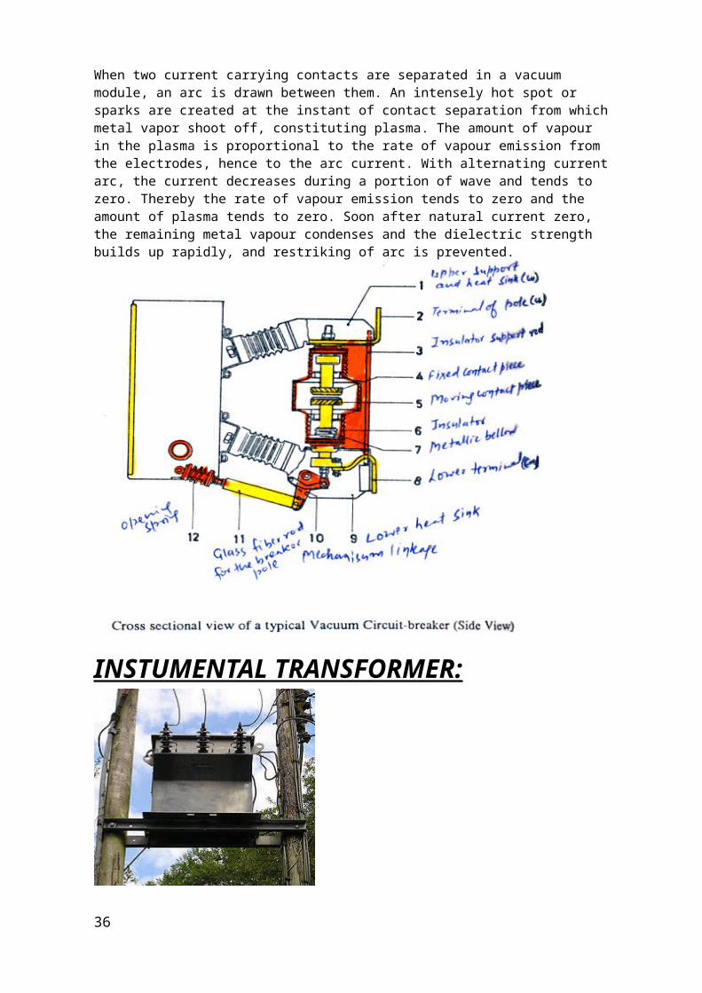
When two current carrying contacts are separated in a vacuum module, an arc is drawn between them. An intensely hot spot or sparks are created at the instant of contact separation from which metal vapor shoot off, constituting plasma. The amount of vapour in the plasma is proportional to the rate of vapour emission from the electrodes, hence to the arc current. With alternating current arc, the current decreases during a portion of wave and tends to zero. Thereby the rate of vapour emission tends to zero and the amount of plasma tends to zero. Soon after natural current zero, the remaining metal vapour condenses and the dielectric strength builds up rapidly, and restriking of arc is prevented.
33
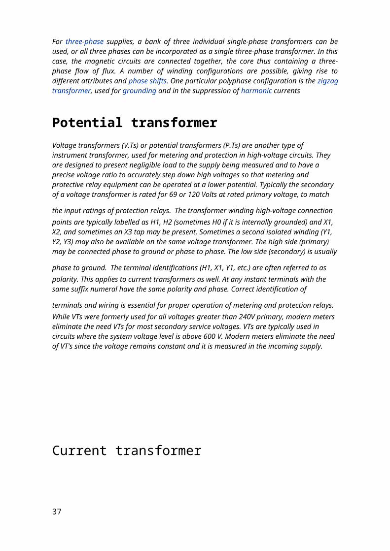
INSTUMENTAL TRANSFORMER:
For three-phase supplies, a bank of three individual single-phase transformers can be used, or all three phases can be incorporated as a single three-phase transformer. In this case, the magnetic circuits are connected together, the core thus containing a three-phase flow of flux. A number of winding configurations are possible, giving rise to different attributes and phase shifts. One particular polyphase configuration is the zigzag transformer, used for grounding and in the suppression of harmonic currents
Potential transformerVoltage transformers (V.Ts) or potential transformers (P.Ts) are another type of instrument transformer, used for metering and protection in high-voltage circuits. They are designed to present negligible load to the supply being measured and to have a precise voltage ratio to accurately step down high voltages so that metering and protective relay equipment can be operated at a lower potential. Typically the secondary of a voltage transformer is rated for 69 or 120 Volts at rated primary voltage, to match the input ratings of
protection relays. The transformer winding high-voltage connection points are typically labelled as H1, H2 (sometimes H0 if it is internally grounded) and X1, X2, and sometimes an X3 tap may be present. Sometimes a second isolated winding (Y1, Y2, Y3) may also be available on the same voltage transformer. The high side (primary) may be connected phase to ground or
phase to phase. The low side (secondary) is usually phase to ground. The terminal identifications (H1, X1, Y1, etc.) are often referred to as polarity. This applies to current transformers as well. At any instant terminals with the same suffix numeral have the same polarity and phase. Correct identification of terminals and wiring is essential for proper operation of metering and
protection relays. While VTs were formerly used for all voltages greater than 240V primary, modern meters eliminate the need VTs for most secondary service voltages. VTs are typically used in circuits where the system voltage level is above 600 V. Modern meters eliminate the need of VT's since the voltage remains constant and it is measured in the incoming supply.
34
Current transformer
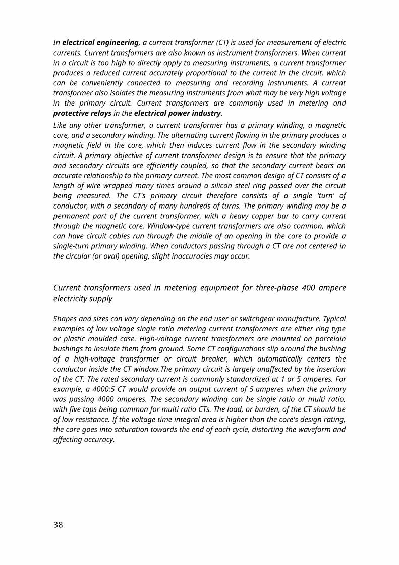
In electrical engineering, a current transformer (CT) is used for measurement of electric currents. Current transformers are also known as instrument transformers. When current in a circuit is too high to directly apply to measuring instruments, a current transformer produces a reduced current accurately proportional to the current in the circuit, which can be conveniently connected to measuring and recording instruments. A current transformer also isolates the measuring instruments from what may be very high voltage in the primary circuit. Current transformers are commonly used in metering and protective relays in the electrical power industry.Like any other transformer, a current transformer has a primary winding, a magnetic core, and a secondary winding. The alternating current flowing in the primary produces a magnetic field in the core, which then induces current flow in the secondary winding circuit. A primary objective of current transformer design is to ensure that the primary and secondary circuits are efficiently coupled, so that the secondary current bears an accurate relationship to the primary current. The most common design of CT consists of a length of wire wrapped many times around a silicon steel ring passed over the circuit being measured. The CT's primary circuit therefore consists of a single 'turn' of conductor, with a secondary of many hundreds of turns. The primary winding may be a permanent part of the current transformer, with a heavy copper bar to carry current through the magnetic core. Window-type current transformers are also common, which can have circuit cables run through the middle of an opening in the core to provide a single-turn primary winding. When conductors passing through a CT are not centered in the circular (or oval) opening, slight inaccuracies may occur.
Current transformers used in metering equipment for three-phase 400 ampere electricity supply
Shapes and sizes can vary depending on the end user or switchgear manufacture. Typical examples of low voltage single ratio metering current transformers are either ring type or plastic moulded case. High-voltage current transformers are mounted on porcelain bushings to insulate them from ground. Some CT configurations slip around the bushing of a high-voltage transformer or circuit breaker, which automatically centers the conductor inside the CT window.The primary circuit is largely unaffected by the insertion of the CT. The rated secondary current is commonly standardized at 1 or 5 amperes. For example, a 4000:5 CT would provide an output current of 5 amperes when the primary was passing 4000 amperes. The secondary winding can be single ratio or multi ratio, with five taps being common for multi ratio CTs. The load, or burden, of the CT should be of low resistance. If the voltage time integral area is higher than the core's design rating, the core goes into saturation towards the end of each cycle, distorting the waveform and affecting accuracy.
35
Bus:An electrical bus (sometimes spelled buss) is a physical electrical interface where many devices share the same electric connection. This allows signals to be transferred between devices (allowing information or power to be shared). A bus often takes the form of an array of wires that terminate at a connector which allows a device to be plugged onto the bus.An electrical bus assembly, having pairs of bus conductors in communication with each other, housed in a housing, for use in an industrial setting. The pairs of bus conductors are themselves used to form a joint without the need of additional apparatus. A first coupling embodiment provides a two-piece clamp having a built-in depression formed therein for applying additional clamping pressure when bolted to the housing surrounding a layered pair of bus conductors. Mylar film is provided for insulating the pair of bus conductors from both the housing and other pairs of bus conductors within a bus assembly. The electrical bus assembly is adaptable to a variety of electrical loads, and is reusable. A second coupling embodiment provides a slotted connecting bus conductor, received by a pair of stationary bus conductors housed in a panel box housing. Fiberglass board insulation isolates the bus conductors from the housing and positions the pair of stationary bus conductors in a spaced apart position for receipt of the slotted bus conductor. When the slotted connecting bus conductor is in position sandwiched between the pair of stationary bus conductors, electrical current passes through all bus conductors.
Types of buses High tension bus: All high tension buses are charged at 6.6KV. There are four high tension buses. All the high tension motors are present over these buses. These buses are further divided in two sub buses:-Unit bus :- the unit bus is charged by the unit transformer or simply we can say that all the motors over this bus are charged by the power generated by the unit generator. Unit buses are 7CA and 7CB.Station bus :- the station bus is charged by the station transformer or simply we can say that this bus is charged by the power that plant carried out from the other thermal plants. Station buses are OCA and OCB.
Low tension bus: all low tension buses are charged at 415V. This voltage is coming from high tension bus by using step down transformer. All the low tension motors are present over these buses. There are 12 low tension buses:-Ash handling plant busWater treatment plant bus
36
Water recovery plant busCoal handling plant busCooling water plant busRaw water plant busDemineralization plant busElectrostatic precipitation bus etc.
Emergency bus:- this bus is also work at 415V same as low tension bus but the only difference is that it is charged by diesel generator. Over this bus all the necessary motors and equipments are present. in case over plant trip there are some motors and equipments has to keep on working so for this we use diesel generator to run these things. Few such things are:-Bearing gearJacking oil pumpSeal oil pumpEmergency oil pump Lubrication oil pump etc.
ELECTRIC SUPPLY SYSTEM:The electric supply system under goes many changes from the point of production to the consumer. A brief description of the various systems as we follows:-
220KV:220kv system is used for the transmission of electricity, because at high voltage the current is very small and hence the losses are minimized. Therefore the transmission is mostly carried out at 220kv.
11KV:11kv can not be used practically. Actually this the voltage at which production takes place i.e. this is the out put voltage of the generator. 6.6KV:6.6KV system of supply is used for High- Tension machinery in thermal power plant and in some industries. The High- Tension motors used in thermal itself are:-
1. F.D. Fan2. I.D. Fan3. P.A. Fan4. B.F. Pump5. C.E. Pump6. C.W. Pump etc.
415V: 415V supply system is used for the Low-Tension machinery. This voltage also serves as the electric supply system for the domestic loads. The Low-Tension motors that works on the 415V are:-
1. Bearing cooling water motor2. Instrument air compressor 3. Service air compressor4. Ash slurry motor5. Seal water pump etc.
37
MOTOR:High tension motorHigh tension motors operated at high voltagesIn Panipat thermal power station, these motors are operated at 6.6kv. Some of these motors are as follows:-
Circulating water pump:-Specifications:-Maker – B.H.E.LCapacity (k.w.)-1965Rated r.p.m.-498Rated current-200AConnections-starDuty- continuousInsulation class-fInstallation position- verticalQuantity-3Function:- C.W. pump is used to circulate cooling water to the condensers so that low pressure steam in the cylinder can be converted into water.Condensate extaction pump:-Specifications:-Make– B.H.E.L Capacity-325kwRated voltage-6600vRated r.p.m.-1485Rated current-35.5AConnections-starDuty- continuousInsulation class-fInsulation position-verticalQuantity-3
Function:-C.E. pump is used to extract the condense water from the hot well and supply to the deareator after passing through l.p. heater& economiser, so that high pressure steam in the cylinder can be created.
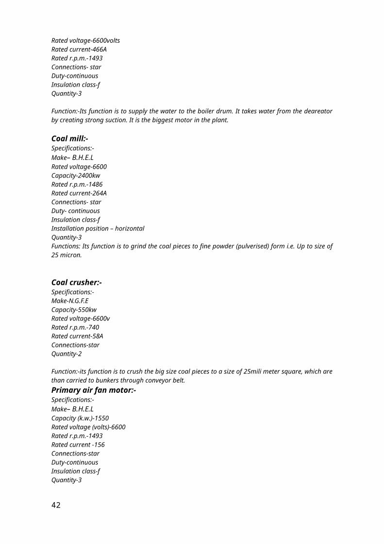
Boiler feed pump:-Specifications:-Make– B.H.E.LCapacity-4600kwRated voltage-6600voltsRated current-466ARated r.p.m.-1493Connections- starDuty-continuousInsulation class-fQuantity-3
Function:-Its function is to supply the water to the boiler drum. It takes water from the deareator by creating strong suction. It is the biggest motor in the plant.
Coal mill:-Specifications:-Make– B.H.E.L
38
Rated voltage-6600Capacity-2400kwRated r.p.m.-1486Rated current-264AConnections- starDuty- continuousInsulation class-fInstallation position – horizontalQuantity-3Functions: Its function is to grind the coal pieces to fine powder (pulverised) form i.e. Up to size of 25 micron.
Coal crusher:-Specifications:-Make-N.G.F.ECapacity-550kwRated voltage-6600vRated r.p.m.-740Rated current-58AConnections-starQuantity-2
Function:-its function is to crush the big size coal pieces to a size of 25mili meter square, which are than carried to bunkers through conveyor belt.Primary air fan motor:-Specifications:-Make– B.H.E.L Capacity (k.w.)-1550Rated voltage (volts)-6600Rated r.p.m.-1493Rated current -156Connections-starDuty-continuousInsulation class-fQuantity-3
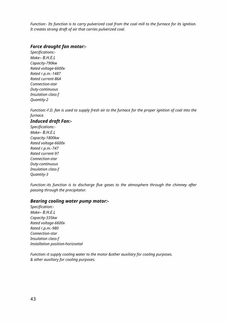
Function:- Its function is to carry pulverized coal from the coal mill to the furnace for its ignition. It creates strong draft of air that carries pulverized coal.
Force draught fan motor:-Specifications:-Make– B.H.E.LCapacity-790kwRated voltage-6600vRated r.p.m.-1487Rated current-86AConnection-starDuty-continuousInsulation class-fQuantity-2
Function:-F.D. fan is used to supply fresh air to the furnace for the proper ignition of coal into the furnace.Induced draft Fan:-Specifications:-Make– B.H.E.LCapacity-1800kwRated voltage-6600v
39
Rated r.p.m.-747Rated current-97Connection-starDuty-continuousInsulation class-fQuantity-3
Function:-its function is to discharge flue gases to the atmosphere through the chimney after passing through the precipitator.
Bearing cooling water pump motor:-Specification:-Make– B.H.E.LCapacity-335kwRated voltage-6600vRated r.p.m.-980Connection-starInsulation class-fInstallation position-horizontal
Function:-it supply cooling water to the motor &other auxiliary for cooling purposes.& other auxiliary for cooling purposes.
Low tension motor
Low tension motors are those which are of 415v. They are mainly used in h.t. motor auxiliary.
B.C.W. drain motor:-Specification:-
Capacity-120kwRated r.p.m.-987Rated current-200AFrequency-50HzMake- KriloskerInsulation class-b
Function:-It pumps the B.C Water to the sump.
Seal water pump motor:-Specification:-
Capacity-25kwRated r.p.m. - 1479Rated current – 43AFrequency 50 HzPhase-3Make –N.G.E.FInsulation class –b
Function – it provides a layer of water to the lower position of boiler in order to seal it from the entry of atmospheric air.Seal water vapour exhaust fan:-40
Specifications –
Capacity – 1.5kwRated r.p.m. – 6205Rated current – 3.1AFrequency – 50 HzPhase –3Make – KirloskerInsulation class –b
Function- it prevents the entry of air bubbles in the turbine cylinder by providing the opposite push.
Centrifuge pump motor:-Specifications –
Capacity –7.5kw Rated r.p.m-1440Rated current-14AFrequency 50 HzPhase – 3Make – Crompton GreavesInsulation class – b
Function – to centrifuge the vapour that enters by change in turbine an remove them
Ash slurry pump motor: –Specifications –
Capacity – 100kwRated r.p.m. – 1485Rated current – 176AFrequency – 50 HzPhase - 3Make – N.G.E.FInsulation class – b
Function – to pump ash slurry to the ash disposal area.
Emergency oil pump: –Specifications-
Capacity – 15kwRated r.p.m. – 1425Rated current – 125AFrequency – DCPhase – not applicableMake – Crompton GreavesInsulation class – b
Function – to provide oil to the shaft and bearing of the turbine if seal oil pump and taking oil pump fails.
41
Raw water motor pump:–Specifications-
Capacity-90kwRated r.p.m.-1450Rated current-154AFrequency-50HzPhase-3Make- KirloskerInsulation class-b
Function-it is use to pump raw water from the lake to the plant.
Instrument air compressor:-Specifications:-
Capacity-105kwRated r.p.m-1485Rated current-184AFrequency-50HzPhase-3Make- KirloskerInsulation class- b
Function- it is used to compress the air used to control pneumatic controlled instruments at a pressure 6 to 7 kg/cm cube.
Service air compressor:-Specifications-
Capacity-30kwRated r.p.m.-1485Rated current-184AFrequency-50HzPhase-3Make-N.G.E.FInsulation class-b
Function- its function is similar to instrument air compressor.
Clarifier water pump motor-Specification-
Capacity-30kwRated r.p.m-1470Rated current-53AFrequency-50HzPhase-3Make- Crompton GreavesInsulation class-b
Function- it pump the filtered water from clearifier to d.m. Water treatment plant.
42
Main oil pump-Specification-
Capacity-111.8kwRated r.p.m-593Rated current-214AFrequency-50HzPhase-3Make- Crompton GreavesInsulation class-f Function- it is the main pump. It supply the oil for the lubrication of the turbine during working.
Seal air fan-Specification-
Capacity-120kwRated r.p.m-2960Rated current-195AFrequency-50HzPhase-3Make- Crompton GreavesInsulation class-f
Function-
Heavy fuel oil pump-Specification-
Capacity-37kwRated r.p.m-1455Rated current-62AFrequency-50HzPhase-3Make- KirloskerInsulation class-f
Function- it pump the heavy oil to the furnace for the combustion of the coal.
Coal mill feeder-Specification-
Capacity-5.5kwRated r.p.m-1440Rated current-11AFrequency-50HzPhase-3Make- Crompton GreavesInsulation class-f
Fuction-43