tp-201 tp-202 tp-203 tp-202l tp-201ce tp-202ce tp...
TRANSCRIPT
SEMI AUTOMATIC POLYPROPYLENE
STRAPPING MACHINE TP-201 TP-202 TP-203 TP-202L
TP-201CE TP-202CE TP-203CE TP-202LCE
TP-201Y TP-201YS
OPERATION MANUAL &
SPARE PARTS LIST
Original Instruction
READ ALL INSTRUCTIONS BEFORE OPERATING THIS PRODUCT

PART I
CONTENTS
1. Safety Instructions................................................................................. 1
2. Construction and Units.......................................................................... 2
3. General Safety Remarks........................................................................ 3
4. Machine Information............................................................................. 5
5. Machine and Operating Element......................................................... 10
6. Operating the Machine.........................................................................11
7. Adjustments ........................................................................................ 12
8. Maintenance & Lubrication ................................................................ 14
9. Troubleshooting Guide........................................................................ 16
10. Wiring Diagram .................................................................................. 19
-1-
1. Safety Instructions
THIS MANUAL GIVES YOU INFORMATION ON SAFETY INSTRUCTIONS,
SPECIFICATIONS, OPERATION AND MAINTENANCE OF STRAPPING
MACHINES.
BEFORE OPERATING OR SERVICING THE MACHINE, PLEASE REVIEW THE
ENTIRE MANUAL AND FOLLOW THE SAFETY INSTRUCTIONS CAREFULLY.
(1) Before Operating a. Verify that the power line voltage is correct.
b. The machine must be properly grounded to avoid a shock hazard. All wiring must be
in accordance with local wiring standards.
c. The strapping machine can only be operated with polypropylene (P.P.) strapping; do
not use polyester (PET) strapping or polyethylene (PE) cord strap.
(2) During Operation a. The weight of the package cannot exceed 100 kg (220 lbs).
b. The size of the package should not be less than 80mm (width) × 20mm (high) (3.16"
×0.79").
c. Check if the machine emits any smokes or unusual sound when it is running.
(3) After operating
a. Remove dust and dirt from the unit; pay particular attention to the interior of the arch.
b. Turn off the power when the machine is not in use.
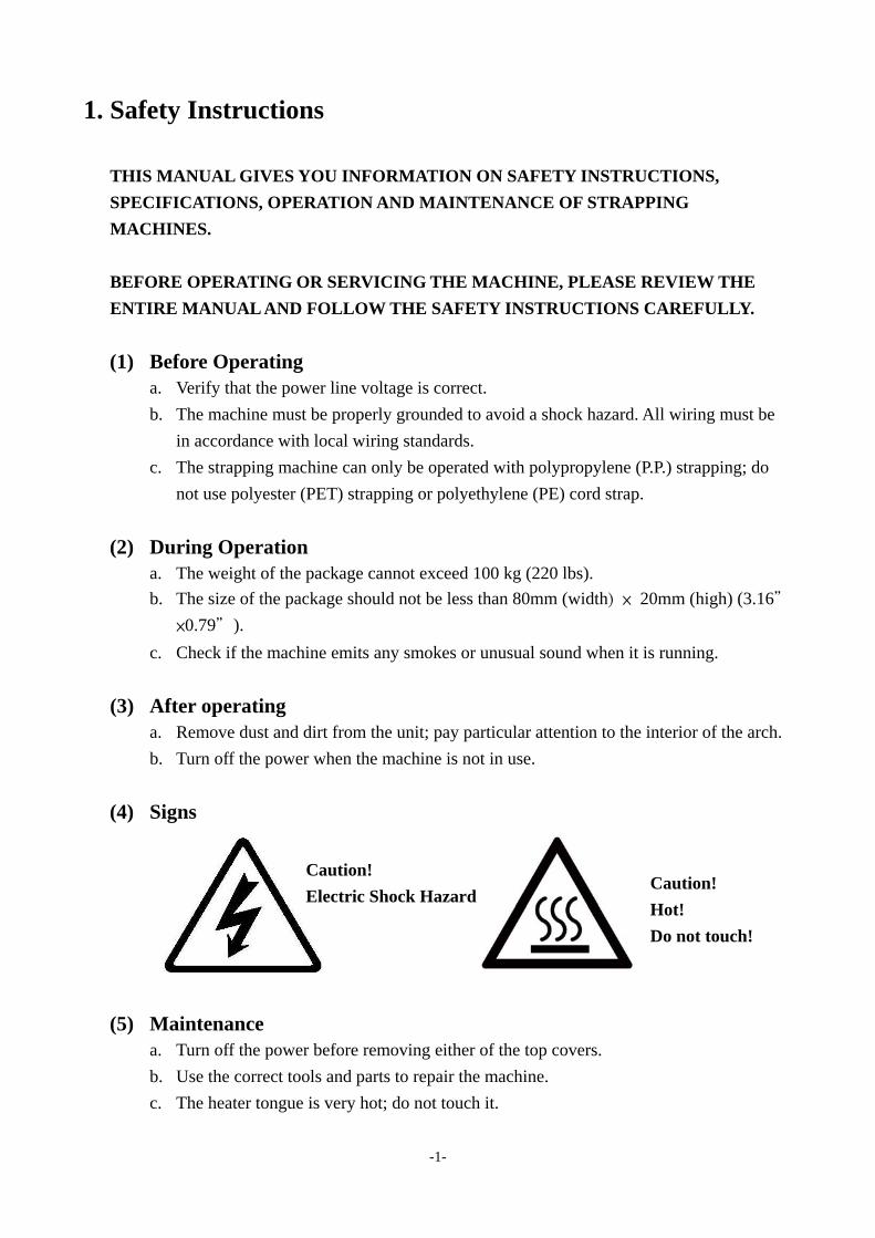
(4) Signs
(5) Maintenance a. Turn off the power before removing either of the top covers.
b. Use the correct tools and parts to repair the machine.
c. The heater tongue is very hot; do not touch it.
Caution!
Electric Shock Hazard Caution!
Hot!
Do not touch!
-2-
(6) Storage a. The store room must be dry.
b. Do not expose the machine to extreme cold or heat environment.
c. Place the machine on an even floor in order to avoid any distortion.
(7) Other Reminders a. Do not alter or bypass protective interlocks.
b. An operation manual must remain attached to the machine at all times.
c. Do not alter the equipment or circuitry unless authorized to do so by the manufacturer.
d. Do not operate the machine with the table tops or covers removed.
e. Never put any part of your body near, under or into a moving machine.
f. Do not overload the machine by exceeding the performance limitations specified in
this manual.
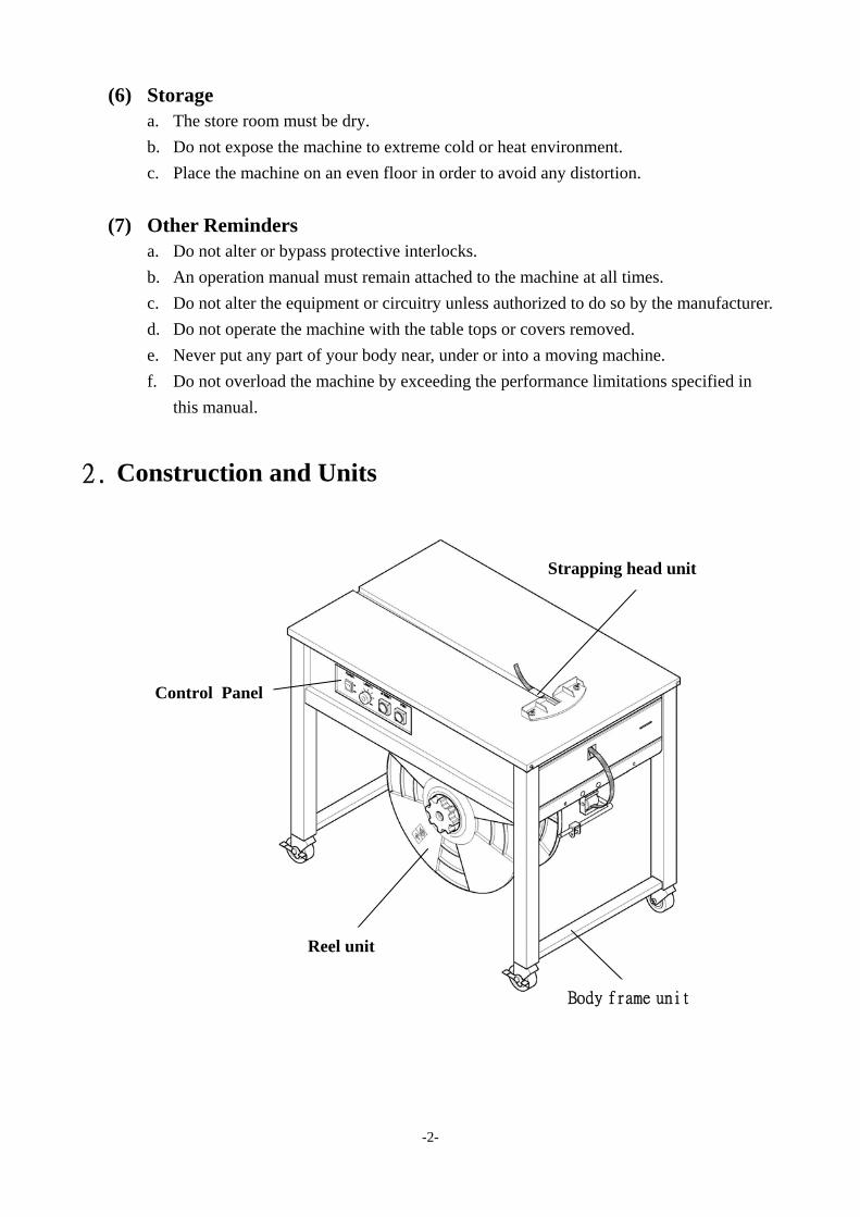
2. Construction and Units
Strapping head unit
Control Panel
Reel unit
Body frame unit

-3-
3. General Safety Remarks
(1) Basic Operation The manual and the safety remarks are to be read before use. The operator manual should
be kept with the machine at all times. Intervals for maintenance and inspections are to be
adhered to.
This machine was built with state of the art technology and rigid adherence to safety
standards.
Unless used properly, it can cause injury to operators or persons in close proximity to the
machine. In addition, improper use can cause damage to the machine or property around
the machine.
(2) Basic Safety Precautions The user is to be instructed in all other generally applicable legal and other mandatory
regulations relevant to accident prevention and environmental protection in addition to the
operating instructions.
For safety reasons, long hair must be tied back or otherwise secured, garments must be
close fitting and no jewelry may be worn.
Use protective equipment whenever required by circumstances or by law.
Carefully observe all safety instructions and warnings attached to the machine and make
sure that they are always complete and perfectly legible.
Always make certain that persons being trained and instructed in working on or with the
machine are permanently supervised by an experienced person.
Work on the electrical system and equipment of the machine is only to be carried out by a
skilled electrician or by persons under the supervision and guidance of a skilled electrician
and in accordance with the rules and regulations of electrical engineering.
(3) Safety Instructions Governing Specific Operational Phases Avoid any operation mode that might be unsafe.
All necessary precautions to ensure that the machine is only used being in a safe and
reliable state are to be taken. The machine is only to be operated if all protective and
safety devices, including removable safety devices, emergency shut-off equipment,
noise-protection elements and exhaust systems are in right place and fully functional.
The machine is to be checked for damage and defects at least once per work shift. Any
changes including the working behavior of the machine are to be reported to competent

-4-
persons immediately. If necessary, the machine is to be stopped and locked immediately.
In case of any malfunction the machine must be stopped and locked until the defect has
been eliminated.
Generally make sure that nobody is at risk before starting up the machine.
All personnel that will be operating this machine should be thoroughly trained in all
phases of operation and safety.
Always tighten unscrewed connections after maintenance and repair.
After completing maintenance and repair, all safety devices removed for setting up or
repairing the machine must be reinstalled and checked for functionality prior to putting the
machine back into service.
To minimize the environmental impact all consumables and replaced parts must be
disposed of safely.
Before starting the machine, check that the accessories have been stowed away safely.
Do not attempt any operation that may be a risk to the stability of the machine.
(4) Warning of Electrical Dangers
Immediately remove power to the machine in case of trouble in the electrical system.
Replace a fuse with one with the same style and ratings; pay particular attention to
matching the specified current.
Any electrical work performed on the equipment must be conducted by a skilled
electrician or under the supervision of a skilled electrician. All work must be observed
good electrical engineering practice and follow safety rules and local wiring standards.
Inspect the electrical equipment of the machine at regular intervals. Tighten any loose
connections. Check wiring for scorch marks; replace scorched wiring and determine and
correct the reason for the overheating.
When working on live equipment, ensure that a second person is available to cut power in
case of an emergency. When appropriate, secure the working area with safety tape and a
warning sign. Use insulated tools for electrical work.
Before working on high-voltage assemblies, turn off the power supply. Carefully discharge
the supply cable and short-circuit any energy-storage components such as capacitors.
If the equipment was moved, carefully refit and refasten all parts removed for transport
before reapplying power.
Before moving the machine, remember to disconnect the power cable.

-5-
(5) Grounding Instructions Shall Include the Following
This product must be grounded. In the event of an electrical short circuit, grounding
reduces the risk of electric shock. This product is equipped with a cord that has a
grounding wire and an appropriate grounding plug. The plug must be plugged into an
outlet that is properly installed and grounded in accordance with all local codes and
ordinances.
If repair or replacement of the cord or plug is necessary, connect the ground wire to the
ground terminal of the plug. The wire with green insulation (with or without yellow stripes)
is the grounding wire.
Check with a qualified electrician or service person if the grounding instructions are not
clear or if in doubt about the proper grounding of the machine. Do not modify the plug
provided; if it will not fit the power outlet, have the proper outlet installed by a qualified
electrician.
This product is designed for use on a nominal 120 (230) volt AC circuit and has a
grounding plug.
DANGER!
Improper installation of the grounding can result in electrocution.
4. Machine Information
(1) Areas of Application and Machine Description
This plastic strapping machine can be used for a wide range of applications where the
minimum package width is at least 80mm, and the minimum height is 20mm.
This machine is particularly suitable for heavy packaged goods as well as printed products,
boxes, etc.
Machine Description
Semi-automatic plastic strapping machine for use with polypropylene strapping.
Heavy duty construction.
Simple, safe and user-friendly operation.
Moveable, with large table area high capacity strap reel and stainless steel table.
Two locking castors, to ensure safe operation.

-6-
Environment Information
The strapping machine shall be installed in the following conditions:
Supply voltage: 0.9 - 1.1 nominal supply voltage
Source frequency: 0.99 - 1.01 nominal frequency
Ambient temperature: 5°C - 40°C (41-104).
Relative humidity: not exceed 50% at 40°C.
Please provide a suitable illumination around the machine for safety operation.
(2) The Safety Devices
Caution!
The heating unit operates at a very high temperature in order to melt the P.P. strapping. To prevent burns, avoid contact with this area. (1)
To move the machine, the two lockable casters (2) must be unlocked. Relock the two
casters when the machine is in its new position.
Description of the Safety Devices
The machine is turned on when it is connected to AC power and the main power switch
(QS1), located on the front operating panel, is placed in the ON position. After
approximately 3 minutes, the heating element will reach its operating temperature and the
machine will be ready for use.
If it is necessary to make adjustments inside the machine during operation, after a strap
jam for example, the table top can be unscrewed. Observe caution as the machine is still
fully functional with the covers removed. If machine with safety switch, when table top is
opened, safety switch is activated.
1
2

-7-
(3) Electrical Specifications
System configuration: 1L+N+PE (Ground) 1L+N+PE (Ground)
Nominal power: 0.5 KW 0.5 KW
Rated current: 7A 10A
Rated voltage: 220V/230V/240V 110V
Rated frequency: 50Hz 60Hz
Type of current: AC - single phase AC - single phase
Minimum Requirements
The electrical supply line for the machine must have a minimum cross-section of at least
3C × 1.0mm2.
(4) Technical Data a. TP-201 / TP-201CE
b. TP-202 / TP-202CE
MODEL TP-201 / TP-201CE
Sealing method Heat
Net Weight 100kg (220 lbs)
Max. Tension 45kg (99 lbs)
Strap Width 6mm to 15.5mm (1/4" to 5/8")
Noise emission 78 dB (A)
Ambient temp 5 Co ~ 40 Co (41 Fo ~ 104 Fo )
MODEL TP-202 / TP-202CE
Sealing method Heat
Net Weight 85kg (187 lbs)
Max. Tension 45kg (99 lbs)
Strap Width 6mm to 15.5mm (1/4" to 5/8")
Noise emission 78 dB (A)
Ambient temp 5 Co ~ 40 Co (41 Fo ~ 104 Fo )

-8-
c. TP-202L / TP-202LCE
d. TP-203 / TP-203CE
e. TP-201Y / TP-201YS
MODEL TP-202L / TP-202LCE
Sealing method Heat
Net Weight 80kg (176 lbs)
Max. Tension 45kg (99 lbs)
Strap Width 6mm to 15.5mm (1/4" to 5/8")
Noise emission 78 dB (A)
Ambient temp 5 Co ~ 40 Co (41 Fo ~ 104 Fo )
MODEL TP-203 / TP-203CE
Sealing method Heat
Net Weight 80kg (176 lbs)
Max. Tension 9kg ~ 30kg (19.8 lbs ~ 66.1 lbs)
Strap Width 6mm to 15.5mm (1/4" to 5/8")
Noise emission 78 dB (A)
Ambient temp 5 Co ~ 40 Co (41 Fo ~ 104 Fo )
MODEL TP-201Y / TP-201YS
Sealing method Heat
Net Weight 125kg (275 lbs)
Max. Tension 45kg (99 lbs)
Strap Width 6mm to 15.5mm (1/4" to 5/8")
Noise emission 78 dB (A)
Ambient temp 5 Co ~ 40 Co (41 Fo ~ 104 Fo )

-9-
(5) How to Remove/Handle the Machine from the Pallet
Two people stand on each side of the machine and remove the machine from the pallet to
the floor.

-10-
5. Machine and Operating Element
(1) Power Switch The motor starts running when this switch is turned ON.
(2) Feeding Length Knob Strap is automatically fed during the time preset by the knob.
(3) Reset Button To pull strap back into machine and / or to cut off strap.
(4) Strap Feed Button To feed strap out of machine freely.
(5) Power Plug To be connected to a 110V or 220V/230V/240V source.
(6) Strap Reel Slide on strap coil here. (If strap core is 280mm, you can
take off the center drum to have core size 200mm.)
(7) Brake Stops the over-rotation of the Strap reel.
(8) Strap Guide for Brake The strap is threaded through this guide.
(9) Strap Bypass Guide The strap is passed through this guide.
(10) Strap Insertion Inlet This is the strap inlet at which the leading strap end is
detected.
(11) Tension control Turn clockwise to increase tension and counter clockwise to
decrease tension
11

-11-
6. Operating the Machine
(1) Operation Space
Keep the area (A) and (B) free for the operator.
The area (A) is necessary for operation strapping machine or changing the strap coil
(TP-202).
For TP-201/TP-203, the area (B) is necessary for changing the strap coil.
(2) How to Load and Thread P.P. Strap
a. Turn reel nut handle (A) left and remove it.
b. Remove the outer flange (B) and install the strap reel.
c. Make sure that the direction of rotation is counterclockwise (E) when unrolling.
d. Put the outer flange back on and tighten reel nut handle (A) to the right.
e. Remove all adhesive strips or other adhesive material.
f. Unroll about 1.5 m of strap and make sure that it is not twisted.
g. Thread the strap over (C) to roller (D) in direction of the arrow.
h. Turn left button (strap feed) to the left until obtaining the length you need.
A A
B
TP-202 TP-201 / TP-203
D
C
BA
E
B

-12-
(3) How to Operate a. Turn the power switch ON. The heating element reaches the working temperature at
approximately 3 minute.
b. Place a package on the table top (The package must cover the Slide Table).
c. Properly adjust the strap tension according to various package.
d. Place the strap around the package to be strapped and insert the strap into the strapping
head until it stops.
e. The strapping and welding sequence should complete.
f. At end of strapping sequence the strap end is fed automatically, and Feeding Length
Knob is to adjust the strap length.
7. Adjustments
(1) Strap Width Adjustment for strap in different width can be done with only one Philips recess
screw driver and a hex spanner. The adjustment must be made in two places, A (Strap
Outlet), B (Strap Inlet) as shown below.
For A, the width of band guide should be at 12.5mm to 13.0mm when using 9mm and
12mm strap and the width of band guide should be at 15.5mm to 16mm when using 15mm
strap.
For B, The width of band guide should be wider by 0.5mm to 1.0mm than the actual
strap width.
The adjustment is made with the
guide located on the top of the
table. Make both adjustments
by loosening two screws and
applying the strap which is to be
used.
Fig. A Strap Outlet
Fig. B Strap Inlet

-13-
(2) Inside Tension Adjustment (For TP-201Y)
Tensioning strength should be adjusted properly by observing the tension of the strap
applied around the package.
The adjustment is made by tensioning adjustment nut A. Tensioning adjustment nut A is
turned clockwise to increase the strength and counterclockwise to decrease strength.
After adjustment, nut A should be fixed by a set screw.
(3) Outside Tension Adjustment (For TP-201/TP-202/TP-203/TP-202L)
The adjustment is made by tensioning adjustment nut A which is located at the back of the
machine.
Tensioning adjustment nut A is turned clockwise to increase the strength and
counterclockwise to decrease strength.

-14-
(4) Heater temperature
Set the knob to position 3 or 4. Adjust the heater temperature by selecting a position
between l and 6. Choose the suitable temperature, bearing in mind the environmental
conditions of the machine. If the heater temperature is too high or too low, a proper seal
will not be obtained.
Gradually increase or reduce the position until obtaining an optimum seal.
8. Maintenance & Lubrication
Warning: Before any maintenance or repairs on the machine, set the Power Switch to "O" (OFF). Wait about 5 minutes for cooling down the heater to avoid burns with this area. (1) Cleaning and Lubrication
The high reliability and long service life of the strapping machine will depend on regular
cleaning and maintenance.
ATTENTION!
All the important strap transport components, such as the tension rollers and the
strap guides, must be kept free from oil and grease. (lubricant)
The lubricant has to be non-resinous.
The lubricant is SAE 30

-15-
(2) Maintenance Only use original spare parts supplied by manufacturer.
Daily:
Use air gun to clean the circled positions (nearby the cutters, strap guide daily
Remove plastic residue in the machine.
Weekly:
Lubricate front bar, press bar and rear bar weekly.
Please refer to the above mesh areas for instruction.
Before lubricating, be sure to clean the parts first to avoid mixing oil and debris which
might have a bad effect on machine’s function.
Monthly :( or 3,000 strapping cycles)
Clean both sides of heater plate and polish with fine sandpaper if necessary
ATTENTION: Make sure the welding plate is cool first!!
Check cam rollers of seal head for easy movement. Slide table back to home position
automatically by the spring tension.
Be sure to clean any debris in the tension roller
6 Months:(or 18,000 strapping cycles)
Check heater plate, replace and readjust it if necessary.
Check strap cutter in seal head, replace it if necessary.
Check that connector at wiring loom to printed circuit board is firmly fixed.
Make machine ready for operation. Strap one bundle manually several times, paying
attention to mal-functions, repeat procedure.
Air Air

-16-
1 year :( or 36,000 strapping)
Replace deflection roller if it shows visible changes.
In case of loud noise at bearings: locate them, replace the bearings.
Get machine ready for operation again, strap one bundle manually several times, paying
attention to malfunctions.
9. Troubleshooting Guide
(1) Strap Jams in the Groove
Step1. Turn the power switch off and pull out the strap strongly in tensioning direction.

-17-
Step2. In case this remedy does not work due to strap jam, follow the instructions listed
below.
a. Loosen M5 Set screw (Part No. 5)
b. Remove Pin (Part No. 6) then lift Holder (Part No. 7) and repeat step 1. If this is
not successful, continue
c. Remove Strap Inlet Guides (Page 12 (B))
d. Remove M6 Hexagon Bolts (Part No. 3)
e. Remove Holder Arm (Part No. 4) from Holder (Part No. 7)
f. Lift out Holder (Part No. 7) and eliminate jam.
g. Reassemble from (f.) back to (a.)

-18-
(2) The Strap Does Not Feed Past the Infeed Guide This failure is caused if the front bar is in the raised position (previous cycle has not been
completed). Turn the Power switch "off ", then "on" again.
If this does not eliminate the failure, adjust the lever for LS1 to allow LS1 to be activated
and de-activated correctly.
*More troubleshooting guide is on request.

-19-
10. Wiring Diagram


PART
CONTENTS
1. Spare Parts List …………………………………1


REF.NO. PART NO. DESCRIPTION Q'TY REMARKS
1 TA-900 Strapping Head Unit (For TP-202) 1TA-901 Strapping Head Unit (For TP-201) 1TA-901S Strapping Head Unit (Stainless Steel
Model)(For TP-201CES)1
TA-902 Strapping Head Unit (For TP-201Y) 1TA-902S Strapping Head Unit (Stainless Steel
Model)(For TP-201YS)1
TA-903 Strapping Head Unit (For TP-203) 12 T5-1-10110 Main Body Block 13 TA-003 Cam Shaft 14 KYA050530 Key, 5×5×30 15 KYA0505101 Key, 5×5×101 16 KYA050515 Key, 5×5×15 27 ER12 Snap Ring, E-12 38 TA-008-2 Bearing Support (L) 19 HBS0620 HBS, M6×20 6
10 HBS0645H HBS, M6×45 (H) 111 BR6003ZZ Bearing, 6003ZZ 4
12A TA-012A Grip Cam 112B TA-012B Grip Cam 113 HSS0608G HSS, M6×8 (G) 1314 TA-014 Separator Cam 1
15A TA-015A Rear Bar Cam 115B TA-015B Heater Cam 116 TA-016 Sprocket 117 TA-017-2 Bearing Support (R) 118 TA-018 Pulley 1
20 TA-020 Pulley 1
22 TA-022 Chain 123 TF-002 Micro Switch Bracket 124 TA-024 Back Cam 125 TA-025 Collar 1
27 TA-027 Sprocket 128 TA-028 Housing 1
-2-

REF.NO. PART NO. DESCRIPTION Q'TY REMARKS
29 TA-029 Pin 130 TA-030 Holder 131 PMS0408 PMS, M4×8 632 TA-032 Spring 133 TA-033 Stop Arm 134 TA-034 Clutch Arm 135 TA-035 Shaft 136 KYA050520 Key, 5×5×20 137 TA-037 Clutch Support 138 HBS0616 HBS, M6×16 1439 TF-009 Switch Trigger 140 TA-040 Guide 141 PMS0420 PMS, M4×20 142 TA-042 Gear Box 143 HBS0820 HBS, M8×20 444 TF-022 Washer 145 KYA050525 Key, 5×5×25 2
58 TA-058 Pull Shaft 159 SW06 SW, M6 1960 TA-060 Solenoid Shaft 161 SP0414 Spring Pin, 4×14 162 TF-028 Fan 163 HBS0510 HBS, M5×10 4
67 TA-067 Bar Guide Lid 1
69 TA-069 Press Bar 1TA-069S Press Bar (Stainless Steel Model) 1
70 SP0318 Spring Pin, 3×18 371 TA-071 Return Spring 372 TA-072 Spring Hook 173 TA-073 Spring Hook 374 TA-074 Rear Bar 1
TA-074S Rear Bar (Stainless Steel Model) 1
-3-

REF.NO. PART NO. DESCRIPTION Q'TY REMARKS
75 TA-075 Plunger 376 BR635ZZ Bearing, 635ZZ 477 SP0514 Spring Pin, 5×14 378 TA-078 Spring 379 TA-079 Front Bar 1
TA-079S Front Bar (Stainless Steel Model) 180 TA-080 Slide 1
TA-080S Slide (Stainless Steel Model) 181 HBS0505.2 HBS, M5×5.2 1
HBS0505.2S HBS, M5×5.2 (Stainless Steel Model) 182 SP0314 Spring Pin, 3×14 1
84 PMS0315 PMS, M3×15 685 HN08 HN, M8 286 TA-086 Seal 187 TA-087 Switch Lever 188 TA-088 Seal (Small) 189 TA-089 Spring Hook 190 TA-090 Arm 191 SP0620 Spring Pin, 6×20 192 HBS0525 HBS, M5×25 194 TA-094 Shaft 195 TA-095 Guide (L) 1
TA-095S Guide (L)(Stainless Steel Model) 196 HBS0512 HBS, M5×12 4
HBS0512S HBS, M5×12 (Stainless Steel Model) 4
99 TF-001 Motor (For 110V/60HZ) 1TF-001-1D Motor (For 220V/50HZ) 1TF-001-1B Motor (For 220V/60HZ) 1TF-001-2 Motor (For 240V/50HZ) 1TF-001-B Motor (For 100V, 50/60HZ) 1
-4-

REF.NO. PART NO. DESCRIPTION Q'TY REMARKS
114 TA-114 Spring 1115 TA-003A Cam Ass'y 1116 TA-035A Stop Arm Ass'y 1117 TA-058A Pull Shaft Ass'y 1118 TA-080A Slide Ass'y 1
TA-080AS Slide Ass'y (Stainless Steel Model) 1119 TA-083A Separator Ass'y 1
TA-083AS Separator Ass'y (Stainless Steel Model) 1120 TF-002A Micro Switch Bracket Ass'y 1121 TF-003A D.C.Solenoid Ass'y (For 110V) 1
TF-003A-1 D.C.Solenoid Ass'y 1(For 220V/230V/240V)
122 T5-1-13000 Rear Bar Ass'y 1123 T5-1-14000 Press Bar Ass'y 1124 T5-1-15000 Front Bar Ass'y 1
226 TA-226 Guide (R) 1TA-226S Guide (R)(Stainless Steel Model) 1
227 TB-114 Return Spring 1228 TA-228 Belt 1229 TA-229 Collar 2
236 TA-236 Rubber Buffer 1
238 ER03 Snap Ring, E-3 1239 TA-239 Cutter Holder 1240 HBS0516 HBS, M5×16 4241 TA-241 Spacer 3
244 HSS0506G HSS, M5×6 (G) 2245 HSS0606G HSS, M6×6 (G) 2246 PW06C PW, M6 (C) 16247 HN06 HN, M6 6248 HN04 HN, M4 1249 SW04 SW, M4 4
-5-

REF.NO. PART NO. DESCRIPTION Q'TY REMARKS
250 SW05 SW, M5 5251 PW05 PW, M5 2252 HBS0525H HBS, M5×25 (H) 1253 HN05 HN, M5 2254 SW08 SW, M8 5255 HN03 HN, M3 3256 PW06A PW, M6 (A) 2258 TF-044 Start Capacitor (220V/50HZ) 1
TF-045 Start Capacitor (220V/60HZ,240V/50HZ)
1
TF-046 Start Capacitor (110V/60HZ) 1TF-047 Start Capacitor (100V/50HZ,
100V/60HZ)1
259 TF-006 Micro Switch (LS-1, LS-3) 2260 LA-50082 Label (LS-3) 1261 LA-50080 Label (LS-1) 1262 SW03 SW, M3 8263 LA-50084 Label (SOL-2) 1264 TF-071 Varistor 1265 PW08C PW, M8 (C) 4
-6-


REF.NO. PART NO. DESCRIPTION Q'TY REMARKS
101 PW04 PW, M4 2102 TB-102 Heater Arm 1103 TB-103 Pin 1104 HN08 HN, M8 1105 ER06 Snap Ring, E-6 1106 HBS0440H HBS, M4×40 (H) 2107 TB-107 Side Plate 1
113 TB-113 Heater Ass'y 1114 TB-114 Return Spring 1115 TB-115 Spring 1117 TB-117 Roller 4118 TB-118 Shaft (For Inside Tension Adjustment) 1
TB-118A Shaft (For Outside TensionAdjustment)
1
119 SR15 Stop Ring, S-15 10120 KYA050515 Key, 5×5×15 9121 HSS0506G HSS, M5×6 (G) 2122 TB-122 Shaft 1123 TB-123 Holder 1124 TB-124 Pin 1125 HSS0606G HSS, M6×6 (G) 1126 HSS0508G HSS, M5×8 (G) 3127 TB-127 Gear 3128 TB-128 Collar 7129 TB-129 Feed Gear 1130 TB-130 Spring 1131 HB06100 HB, M6×100 1132 HN06 HN, M6 12133 TB-133 Nut 1134 TB-134 Gear 1135 TB-135 Holder Arm 1136 HBS0616 HBS, M6×16 4137 TB-137 Shaft 1138 KYA050520 Key, 5×5×20 2139 TB-139 Pulley 1140 RR22 Snap Ring, H-22 1
-8-

REF.NO. PART NO. DESCRIPTION Q'TY REMARKS
141 TB-141 Pulley 2142 BR608ZZ Bearing, 608ZZ 1143 TB-143 Round Belt 1144 TB-144 Shaft 1145 ER07 Snap Ring, E-7 1146 TB-146 Arm 1147 RR32 Snap Ring, H-32 2148 TB-148 Bracket 1149 TB-123B Roller Holder Ass'y 1150 TB-210A Roller Bracket Ass'y 1151 PMS0315 PMS, M3×15 2152 TB-152 Shaft 1154 TB-154 Spring 1155 TB-155 Nut 1156 BR6002ZZ Bearing, 6002ZZ 12157 TB-157 V-Belt 1158 TB-158 Bracket 1159 HBS0620 HBS, M6×20 6160 TB-160 Bracket 1161 TB-158A Bracket Ass'y 1162 TB-162 Shaft 1163 KYA050538 Key, 5×5×38 1164 TB-164 Shaft 1165 TB-165 Feed Arm 1166 SP0520 Spring Pin, 5×20 1167 BR635ZZ Bearing, 635ZZ 3168 TB-168 Arm Pin 1169 SW04 SW, M4 6170 TB-170 Pulley 1171 TB-160B Bracket Ass'y 1
173 TB-173 V-Belt 1174 TB-165A Feed Arm Ass'y 1175 TB-175 Plate 1
175A TB-175A Plate 1176 TB-176 Friction Disc 2
TJ-025 Friction Disc (Only TP-203) 2
-9-

REF.NO.
PART NO. DESCRIPTION Q'TY REMARKS
177 TB-177 Pull Shaft 1178 TB-170A Pulley Ass'y 1179 TB-177A Pull Shaft Ass'y 1180 PW06A PW, M6 (A) 19181 SP0414 Spring Pin, 4×14 1
183 TB-183 Spring 1184 TB-184 Stop Bracket 1185 HBS0510 HBS, M5×10 6186 TB-186 Spring 1187 TB-187 Spring 1189 TB-189 Retainer 1
192 TB-192 Roller 1193 TB-193 Cover 1195 TB-195 Outlet Cover 1196 PMS0410 PMS, M4×10 7197 TB-197 Guide Front 1199 TB-199 Pin 1200 SR10 Stop Ring, S-10 2201 TB-201 Outlet Guide 1203 TB-203 Guide 1
TB-203L Guide (Longer)(Option) 1204 FMS0408 FMS, M4×8 10205 TB-205 Guide 1206 TB-206 Cover 1207 TB-207 Cover-Side 2208 TB-208 Front Plate 1209 TB-209 Band Plate 1210 TB-210 Pulley 1212 RR19 Snap Ring, H-19 1213 HBS0525H HBS, M5×25 (H) 1215 TB-215 Collar 1216 HB0680 HB, M6×80 1220 PMS0412 PMS, M4×12 3221 HN05 HN, M5 3
-10-

REF.NO.
PART NO. DESCRIPTION Q'TY REMARKS
223 TB-223 Washer 2224 TB-224 Spring Retainer 2225 TB-225 Bushing 1
231 TB-231 Pin 1232 TB-232 Bracket 1234 HBS0665H HBS, M6×65 (H) 1
246 SR40 Stop Ring, S-40 1247 HBS0506 HBS, M5×6 1248 TB-248 Spring Retainer 1249 BR6005ZZ Bearing, 6005ZZ 1250 TB-250 Tube A 1251 TB-251 Tube B 1
TJ-251 Tube B (Only TP-203) 1254 HBS0512 HBS, M5×12 2255 TB-255 Fix Arm (Only TP-201) 1256 TB-256 Corrector 1257 TB-257 Fix Arm (For TP-202/TP-202L) 1258 TB-258 Bolt (For TP-202/TP-202L) 1260 T7-3-40480 Spring (Only TP-201Y) 1262 TB-262 Tube 1263 HBS0516 HBS, M5×16 1264 HSS0606G HSS, M6×6 (G) 1265 SW08 SW, M8 1266 HN04 HN, M4 7267 PW04 PW, M4 3268 SW05 SW, M5 6269 SW06 SW, M6 15270 PW05 PW, M5 1271 SW03 SW, M3 2272 TF-007 Micro Switch (LS-2) 1273 LA-50081 Label (LS-2) 1274 LA-50083 Label (SOL-1) 1275 TF-071 Varistor 1
-11-
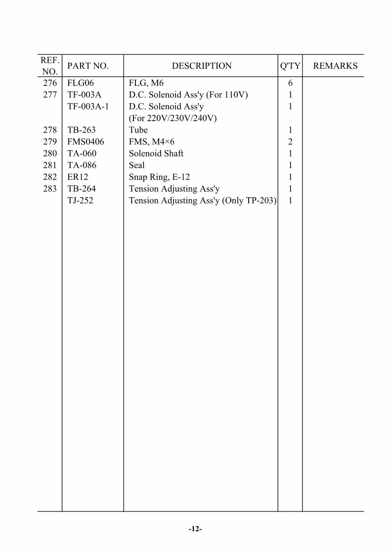
REF.NO. PART NO. DESCRIPTION Q'TY REMARKS
276 FLG06 FLG, M6 6277 TF-003A D.C. Solenoid Ass'y (For 110V) 1
TF-003A-1 D.C. Solenoid Ass'y 1(For 220V/230V/240V)
278 TB-263 Tube 1279 FMS0406 FMS, M4×6 2280 TA-060 Solenoid Shaft 1281 TA-086 Seal 1282 ER12 Snap Ring, E-12 1283 TB-264 Tension Adjusting Ass'y 1
TJ-252 Tension Adjusting Ass'y (Only TP-203) 1
-12-


REF.NO.
PART NO. DESCRIPTION Q'TY REMARKS
1 TE-001 Inner Flange 12 TC-014 Outer Flange 13 TE-003 Shaft 14 TC-015 Protector 15 TB-255-1 Rubber 1
7 TC-016 Reel Nut Handle 18 TC-004 Package Guide 1
10 TE-010 Grommet 211 TE-011 Caster (Free) 212 TE-012 Caster (Brake) 213 TE-013 Lock Pin 4
TE-013S Lock Pin (Stainless Steel Model) 414 TE-014 Brake Holder (R) 115 TC-002 Bracket 116 TC-008 Grommet 117 TE-017 Bushing (L) 118 TE-018 Bushing (R) 119 TC-020 Pin 120 TC-021 Split Pin 121 TE-021 Brake Set 122 TE-022 Pin 123 TE-023 Rubber Stop 124 TE-024 Brake Holder (L) 125 TE-025 Spring 126 ER04 Snap Ring, E-4 227 TE-027 Roller Holder 128 TE-028 Roller 129 TE-029 Pin 130 TE-030 Band Guide Bracket 131 TC-049 Roller 132 TC-048 Shaft 1
38 TMS0508 TMS, M5×8 (Only CE) 640 TE-033 Right Side Plate (Only CE) 1
-14-

REF.NO. PART NO. DESCRIPTION Q'TY REMARKS
41 TE-041 Body Frame 1TE-041S Body Frame (Stainless Steel Model) 1TK-033 Body Frame (Only CE) 1TK-033S Body Frame (Stainless Steel Model)
(Only CE)1
42 TE-042 Magnet Catch 443 TE-043 Side Door (L) 1
TE-043S Side Door (L)(Stainless Steel Model) 144 TE-044 Side Door (R) 1
TE-044S Side Door (R)(Stainless Steel Model) 145 TE-045 Support 1
TE-045S Support (Stainless Steel Model) 146 TC-043 Top Plate 1
TC-043S Top Plate (Stainless Steel Model) 147 TE-001A Reel Unit 148 TE-021A Brake Arm Ass'y 149 TE-030A Band Guide Bracket Ass'y 1
51 HB0612 HB, M6×12 20
53 TMS0305 TMS, M3×5 8
55 HBS0620 HBS, M6×20 756 HB0620 HB, M6×20 257 SW06 SW, M6 2758 SR10 Stop Ring, S-10 359 PW06C PW, M6 (C) 3060 PW06A PW, M6 (A) 261 PW06B PW, M6 (B) 2
63 WN06 WN, M6 264 HN06 HN, M6 11
67 TMS0612 TMS, M6×12 168 TC-068 Collar 169 NTE06 NTE, M6 270 TC-070 Shaft 2
-15-

REF.NO. PART NO. DESCRIPTION Q'TY REMARKS
71 FMS0612 FMS, M6×12 1
73 T5-2-10170 Hinge 1
75 TC-075 Center Drum 280mm 176 TC-076 Washer 177 ER19 Snap Ring, E-19 178 TB-205 Guide 1
84 HBS0612 HBS, M6×12 285 TMS0408 TMS, M4×8 286 SW04 SW, M4 287 HN04 HN, M4 2
89 PW05 PW, M5 490 SW05 SW, M5 491 HN05 HN, M5 4
94 HB0610 HB, M6×10 195 PMS0408 PMS, M4×8 296 LA-31010 Label 1
-16-


REF.NO. PART NO. DESCRIPTION Q'TY REMARKS
1 TC-001 Protection Cover 12 TC-002 Bracket 13 TC-003 Reel Shaft 14 TC-004 Package Guide 15 TC-005 Lid 56 TC-006 Caster (Free) 27 TC-007 Caster (Brake) 28 TC-008 Grommet 19 TC-009 Brake Shaft 1
10 BR6003ZZ Bearing, 6003ZZ 211 TC-011 Washer 113 TC-013 Inner Flange 114 TC-014 Outer Flange 115 TC-015 Protector 116 TC-016 Reel Nut Handle 1
18 TC-018 Brake Lining 119 TC-019 Roller 120 TC-020 Pin 121 TC-021 Split Pin 122 TC-022 Roller Holder 124 TC-024 Brake Adjuster 125 TC-025 Spring 130 T7-5-10160 Adjustment Leg (Option) 431 TC-031 Fix Plate (Option) 432 T5-3-11000 Reel Control Group 133 TC-047A Roller Bracket Ass'y 1
38 TMS0508 TMS, M5×8 639 SW16 SW, M16 441 TC-041 Body Frame 1
TK-031 Body Frame (Only CE) 142 TC-042 Support 143 TC-043 Top Plate 144 TC-044 Reel Support 1
-18-

REF.NO. PART NO. DESCRIPTION Q'TY REMARKS
45 TC-045-1 Fixing Brake Lining Bracket 146 TC-046-1 Arm 147 TC-047 Roller Bracket 148 TC-048 Shaft 149 TC-049 Roller 150 TC-050 Lining Holder 151 HB0612 HB, M6×12 452 PW06C PW, M6 (C) 1453 FMS0512 FMS, M5×12 254 HBS0620 HBS, M6×20 755 SW05 SW, M5 256 PW06A PW, M6 (A)(Option) 8
57 PW05 PW, M5 258 SW06 SW, M6 10
SW06 SW, M6 (Option) 1859 SW08 SW, M8 460 HBS0616 HBS, M6×16 2
HBS0616 HBS, M6×16 (Option) 1061 WN06 WN, M6 262 HN06 HN, M6 963 HBS0816 HBS, M8×16 464 HB0816 HB, M8×16 165 SR20 Stop Ring, S-20 266 SR10 Stop Ring, S-10 267 TMS0612 TMS, M6×12 168 TC-068 Collar 169 NTE06 NTE, M6 270 TC-070 Shaft 271 FMS0612 FMS, M6×12 1
73 T5-2-10170 Hinge 174 PW06B PW, M6 (B) 275 TC-075 Center Drum 280mm 176 TC-100 Adjustment Leg Ass'y (Brake)(Option) 277 TC-110 Adjustment Leg Ass'y (Free)(Option) 278 TB-205 Guide 1
-19-

REF.NO. PART NO. DESCRIPTION Q'TY REMARKS
79 TC-076 Washer 180 ER19 Snap Ring, E-19 181 HBS0525H HBS, M5×25 (H) 182 HN05 HN, M5 483 PMS0416 PMS, M4×16 484 PW04 PW, M4 485 TMS0408 TMS, M4×8 291 SR15 Stop Ring, S-15 192 TC-092 Holder 193 LA-50094 Label (Option) 494 HN05 HN, M5 295 HB0610 HB, M6×10 196 TC-094 Spacer 197 LA-31010 Label 1
-20-


REF.NO. PART NO. DESCRIPTION Q'TY REMARKS
1 TD-001 Protection Cover 12 TC-002 Bracket 13 TD-003 Reel Shaft 14 TC-004 Package Guide 15 TC-005 Lid 56 TC-006 Caster (Free) 27 TC-007 Caster (Brake) 28 TC-008 Grommet 19 TC-009 Brake Shaft 1
10 BR6003ZZ Bearing, 6003ZZ 211 TC-011 Washer 113 TC-013 Inner Flange 114 TC-014 Outer Flange 115 TC-015 Protector 116 TD-016 Reel Nut Handle (LH) 1
18 TD-018 Brake Lining 119 TC-019 Roller 220 TC-020 Pin 121 TC-021 Split Pin 122 TC-022 Roller Holder 124 TD-024 Spring Hook 125 TC-025 Spring 1
38 TMS0508 TMS, M5×x8 639 SW16 SW, M16 441 TD-041 Body Frame 1
TK-041 Body Frame (Only CE) 142 TC-042 Support 143 TC-043 Top Plate 144 TD-044 Reel Support 145 TC-045-1 Fixing Brake Lining Bracket 146 TD-046-1 Arm 147 TD-047 Roller Bracket 148 TD-048 Shaft 149 TD-044A Reel Support Ass'y 1
-22-

REF.NO. PART NO. DESCRIPTION Q'TY REMARKS
50 TC-050 Lining Holder 151 HB0612 HB, M6×12 252 HB0610 HB, M6×10 253 FMS0512 FMS, M5×12 254 HBS0620 HBS, M6×20 755 SW05 SW, M5 256 PW06C PW, M6 (C) 1457 PW05 PW, M5 258 SW06 SW, M6 1459 TD-047A Roller Bracket Ass'y 160 PW06B PW, M6 (B) 261 WN06 WN, M6 262 HN06 HN, M6 963 HBS0616 HBS, M6×16 564 HB0816 HB, M8×16 165 SR20 Stop Ring, S-20 266 SR10 Stop Ring, S-10 367 TMS0612 TMS, M6×12 168 TC-068 Collar 169 NTE06 NTE, M6 270 TC-070 Shaft 271 FMS0612 FMS, M6×12 172 PW06A PW, M6 (A) 273 T5-2-10170 Hinge 1
75 TC-075 Center Drum 280mm 176 TC-076 Washer 177 ER19 Snap Ring, E-19 178 TB-205 Guide 1
81 HBS0525H HBS, M5×25 (H) 182 HN05 HN, M5 483 PMS0416 PMS, M4×16 484 PW04 PW, M4 6
-23-

REF.NO. PART NO. DESCRIPTION Q'TY REMARKS
91 SR15 Stop Ring, S-15 192 TMS0408 TMS, M4×8 2
94 HN05 HN, M5 295 HB0610 HB, M6×10 196 TC-094 Spacer 197 LA-30200 Label 198 LA-30210 Label 1
-24-


REF.NO.
PART NO. DESCRIPTION Q'TY REMARKS
1 TE-001 Inner Flange 12 TC-014 Outer Flange 13 TE-003 Shaft 14 TC-015 Protector 17 TC-016 Reel Nut Handle 18 TC-004 Package Guide 1
10 TE-010 Grommet 211 TC-006 Caster (Free) 212 TC-007 Caster (Brake) 213 TE-013 Lock Pin 414 TE-014 Brake Holder (R) 115 TC-002 Bracket 116 TC-008 Grommet 117 TE-017 Bushing (L) 118 TE-018 Bushing (R) 119 TC-020 Pin 120 TC-021 Split Pin 121 TJ-021 Brake Set 122 TE-022 Pin 123 TE-023 Rubber Stop 124 TE-024 Brake Holder (L) 125 TE-025 Spring 126 ER04 Snap Ring, E-4 227 TE-027 Roller Holder 128 TE-028 Roller 129 TE-029 Pin 130 TE-030 Band Guide Bracket 131 TC-049 Roller 132 TC-048 Shaft 1
38 TMS0508 TMS, M5×8 (Only CE) 639 SW16 SW, M16 4
41 TJ-001 Body Frame 1TJ-010 Body Frame (Only CE) 1
42 TE-042 Magnet Catch 443 TJ-043 Side Door (L) 1
-26-

REF.NO. PART NO. DESCRIPTION Q'TY REMARKS
44 TJ-044 Side Door (R) 146 TJ-002 Top Plate 147 TE-001A Reel Unit 148 TE-030A Band Guide Bracket Ass'y 149 TJ-021A Brake Arm Ass'y 1
51 HBS0612 HBS, M6×12 253 TMS0305 TMS, M3×5 854 PW06A PW, M6 (A) 255 HBS0620 HBS, M6×20 756 HB0612 HB, M6×12 457 SW06 SW, M6 958 SR10 Stop Ring, S-10 459 PW06C PW, M6 (C) 1460 PW06B PW, M6 (B) 263 WN06 WN, M6 264 HN06 HN, M6 9
71 TJ-023 Bracket of Smoke-Exhaus Pipe 172 TJ-024 Smoke-Exhaus Pipe 174 TJ-092 Reel Assist Bracket 175 TC-075 Center Drum 280mm 1
77 TC-076 Washer 178 ER19 Snap Ring, E-19 179 TB-205 Guide 1
81 SW04 SW, M4 483 PW05 PW, M5 284 SW05 SW, M5 285 HN05 HN, M5 2
87 PW04 PW, M4 288 HN04 HN, M4 289 PMS0408 PMS, M4×8 490 TMS0408 TMS, M4×8 291 LA-31010 Label 1
-27-


REF.NO. PART NO. DESCRIPTION Q'TY REMARKS
1 TL-001 Body Frame 1TL-001S Body Frame (Stainless Steel Model) 1
2 TL-002 Table (L) 1TL-002S Table (L)(Stainless Steel Model) 1
3 TD-003 Reel Shaft 1TD-003S Reel Shaft (Stainless Steel Model) 1
4 TL-004 Table (R) 1TL-004S Table (R)(Stainless Steel Model) 1
5 TL-005 Top Plate 1TL-005S Top Plate (Stainless Steel Model) 1
7 TL-007 Front Plate 1TL-007S Front Plate (Stainless Steel Model) 1
8 TC-006 Caster (Free) 2TC-006S Caster (Free)(Stainless Steel Model) 2
9 TC-007 Caster (Brake) 2TC-007S Caster (Brake)(Stainless Steel Model) 2
10 TC-019 Roller 211 TL-011 Table Support 1
TL-011S Table Support (Stainless Steel Model) 112 TL-012 Reel Support 1
TL-012S Reel Support (Stainless Steel Model) 113 TC-013 Inner Flange 114 TC-014 Outer Flange 115 TL-015 Guide 1
TL-015S Guide (Stainless Steel Model) 116 TD-016 Reel Nut Handle (LH) 117 TL-017 Back Door 1
TL-017S Back Door (Stainless Steel Model) 118 ER07S Snap Ring, E-7 (SUS) 1619 T6-5-11120 Table Roller 8
T6-5-11121 Table Roller (Plastic) 820 T6-5-11130 Table Roller Shaft 8
T6-5-11131 Table Roller Shaft (Stainless SteelModel)
8
21 TL-021 Brake Arm 1TL-021S Brake Arm (Stainless Steel Model) 1
-29-

REF.NO. PART NO. DESCRIPTION Q'TY REMARKS
22 TE-027 Roller Holder 1TE-027S Roller Holder (Stainless Steel Model) 1
23 TL-023 Stopper 124 TL-024 Bolt 125 HN08 HN, M8 2
HN08S HN, M8 (Stainless Steel Model) 227 FMS0410 FMS, M4×10 4
FMS0410S FMS, M4×10 (Stainless Steel Model) 4
30 TL-030 Brake lining 131 TD-047A Roller Bracket Ass'y 132 TL-007A Front Plate Ass'y 133 T6-4-30000 Reel Control Group 1
T6-4-30000S Reel Control Group (Stainless Steel 1Model)
34 SW16 SW, M16 4SW16S SW, M16 (Stainless Steel Model) 4
41 TL-041 Door Lock 242 TL-042 Bracket 143 TD-047 Roller Bracket 2
TD-047S Roller Bracket (Stainless Steel Model) 244 TD-048 Shaft 2
TD-048S Shaft (Stainless Steel Model) 245 T6-2-11140 RH Strap Guide Flap Pin (Rear) 246 T6-2-11150 RH Strap Guide Flap Spring 247 TL-047 Flap 1
TL-047S Flap (Stainless Steel Model) 1
-30-
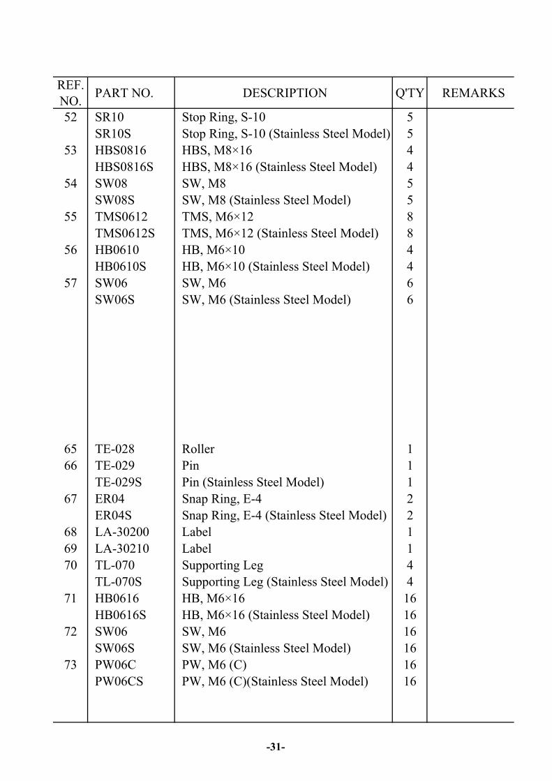
REF.NO. PART NO. DESCRIPTION Q'TY REMARKS
52 SR10 Stop Ring, S-10 5SR10S Stop Ring, S-10 (Stainless Steel Model) 5
53 HBS0816 HBS, M8×16 4HBS0816S HBS, M8×16 (Stainless Steel Model) 4
54 SW08 SW, M8 5SW08S SW, M8 (Stainless Steel Model) 5
55 TMS0612 TMS, M6×12 8TMS0612S TMS, M6×12 (Stainless Steel Model) 8
56 HB0610 HB, M6×10 4HB0610S HB, M6×10 (Stainless Steel Model) 4
57 SW06 SW, M6 6SW06S SW, M6 (Stainless Steel Model) 6
65 TE-028 Roller 166 TE-029 Pin 1
TE-029S Pin (Stainless Steel Model) 167 ER04 Snap Ring, E-4 2
ER04S Snap Ring, E-4 (Stainless Steel Model) 268 LA-30200 Label 169 LA-30210 Label 170 TL-070 Supporting Leg 4
TL-070S Supporting Leg (Stainless Steel Model) 471 HB0616 HB, M6×16 16
HB0616S HB, M6×16 (Stainless Steel Model) 1672 SW06 SW, M6 16
SW06S SW, M6 (Stainless Steel Model) 1673 PW06C PW, M6 (C) 16
PW06CS PW, M6 (C)(Stainless Steel Model) 16
-31-


REF.NO. PART NO. DESCRIPTION Q'TY REMARKS
5 TF-005 Safety Switch Plate (Option) 1
15 TF-015 Terminal Bracket 116 TF-016 Cover (Only CE) 1
18 TF-018 Safety Limit Switch (For CE)(Option) 119 TF-019 Adiabatic Plate 120 TF-020 Fan Cover 121 TF-021 Fan (For 110V) 1
TF-021-1 Fan (For 220V/230V/240V) 122 T7-5-10210 Switch Actuator (Option) 1
23A TF-023A Heater Transformer Ass'y (For 110V) 1TF-023A-1 Heater Transformer Ass'y 1
(For 220V/230V/240V)
24 TF-024 Transformer Cover 125 TF-025 Knob 1
27 TF-027 Selector Switch 128 TG-024 Wire (For TP-201)(Option) 1
TG-025 Wire (For TP-203)(Option) 1TG-026 Wire (For TP-201Y)(Option) 1TG-027 Wire (For Top Plate)(Option) 1
29 TE-099 Safety Limit Switch Ass'y (Option) 130 TF-029 Cover (Only TP-203) 131 TF-031 Switch Cover (Option) 132 LA-40002 Label 1
-33-

REF.NO. PART NO. DESCRIPTION Q'TY REMARKS
41 TJ-022 Fan Support 142 T5-4-10310 Earth Plate (5P)(For CE)(Option ) 143 TK-035 Interlock Safety Switch 1
45 T6-6-10980 Cable Gland (PG11) 1(For TUV CE Version)(Option)
50 TE-097 Safety Limit Switch Ass'y 2(For TP-201CE)
TE-100 Safety Limit Switch Ass'y 2(For TP-203CE)
TE-098 Safety Limit Switch Ass'y 2(For TP-201Y)
51 TMS0512 TMS, M5×12 (Option ) 452 TMS0412 TMS, M4×12 (For CE)(Option ) 153 HB0620 HB, M6×20 254 TMS0408 TMS, M4×8 (Option ) 455 PMS0425 PMS, M4×25 (Option ) 456 PMS0520 PMS, M5×20 457 PMS0410 PMS, M4×10 4
PMS0410 PMS, M4×10 (For TP-201/TP-202) 858 FMS0508 FMS, M5×8 (For TUV CE Version) 2
(Option )59 PMS0412 PMS, M4×12 (For TP-203)(Option) 460 SW04 SW, M4 (For TP-201/TP-202) 4
SW, M4 (For TP-203)(Option) 461 SW06 SW, M6 263 SW05 SW, M5 6
66 PW06C PW, M6 (C) 467 PW05 PW, M5 468 HN06 HN, M6 270 HN04 HN, M4 (Option) 4
-34-

REF.NO. PART NO. DESCRIPTION Q'TY REMARKS
74 TMS0508 TMS, M5×8 275 HN05 HN, M5 4
HN, M5 (For TUV CE Version) 2(Option )
76 PW04 PW, M4 (Option) 4
80 PMS03.515 PMS, M3.5×15 281 PMS0408 PMS, M4×8 282 PW04 PW, M4 1
-35-


REF.NO. PART NO. DESCRIPTION Q'TY REMARKS
1 TG-001 Power Switch 12 TG-002 Variable Resistor (1MΩ) 23 TG-003 Knob 14 TG-004 Reset Push Button Switch 15 TG-005 Feed Push Button Switch 16 TG-006 Control Panel 17 T2-6-30250 PC Board 18 TG-008 PC Board Receptacle 19 TG-009 Base 1
12 TG-012 Knob 113 TG-013 Fuse Holder 114 T6-6-30133 Fuse (10A)(For 110V AC) 1
T6-6-30034 Fuse (7A)(For220V/230V/240V AC) 115 TG-015 Transformer (For 110V) 1
TG-015-1 Transformer (For 220V) 1TG-015-2 Transformer (For 240V) 1
16 TG-016 Bolt 119 TG-019 Power Cord 120 LA-10018 Label 121 TG-021 Switch Cover 122 TG-022 Grommet 123 LA-40001 Label 124 LA-40003 Label 1
30 LA-20170 Label 134 TG-034 Cover 1
51 TMS0408 TMS, M4×8 852 HN04 HN, M4 253 TMS0312 TMS, M3×12 261 TK-001 Main Power Switch (Only CE) 162 PW04 PW, M4 263 PMS0408 PMS, M4×8 264 SW03 SW, M3 2
02/2011
-37-