towards fully automated processing of dmc … · towards fully automated processing of dmc images...
TRANSCRIPT
TOWARDS FULLY AUTOMATED PROCESSING OF DMC IMAGES
Christoph Dörstel 1), Sybille Traub 1), Dan Wuescher 2)
1) Intergraph GmbH, 73431 Aalen, Germany, ([email protected], [email protected] ) 2) Intergraph Corporation, Huntsville (AL), United States ([email protected] )
KEY WORDS: digital aerial camera, automatic, processing workflow ABSTRACT: DMC Post Processing Software (PPS) generates DMC virtual images in 2 processing steps. This paper shortly introduces data post processing of DMC images and discusses how distributed processing (DP) can reduce production times. Users’ requirements and general design aspects are presented and the solution for a distributed processing environment is introduced. Practical experiences from a prototype implementation are shown and future improvements for a fully digital image production workflow are described.
1. INTRODUCTION Main benefit of using the integrated DMC technology (Hinz, 1999, 2001) as an aerial photogrammetric solution is the completely digital workflow, which eliminates the process of scanning and film processing and completely closes the digital chain from image recording to plotting. Management of the complete workflow becomes more and more important. Besides the new digital capabilities, benefits like cost and time saving which will arise from a fully integrated and highly automated workflow have become today’s customer requirements. However, the real advantage of a flexible, fully digital workflow can just be fully discovered by introducing efficient process oriented data management tools to reduce processing times and to chain processing steps to reach high automation and data throughput. The design of the DMC software supports to split the post processing task into radiometric processing, geometric processing and optionally image dodging. Thus in principle distributed post processing may help to reduce processing times. In the following the implementation and design aspects of DP for DMC images is explained and the efficiency as well as limitations shown, based on practical experience with a first prototype.
2. TERRASHARE TECHNOLOGY TerraShare, introduced by Z/I Imaging in 2001, is an enterprise system for geospatial data management and earth imaging production and integrates storage infrastructure with end-user production and exploitation tools to address users geospatial data management, access, and distribution needs.
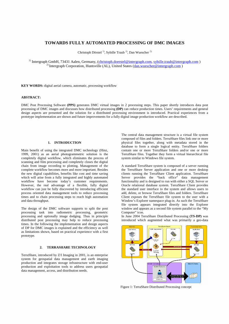
The central data management structure is a virtual file system composed of files and folders. TerraShare files link one or more physical files together, along with metadata stored in the database to form a single logical entity. TerraShare folders contain one or more TerraShare folders and/or one or more TerraShare files. Together they form a virtual hierarchical file system similar to Windows file system. A standard TerraShare system is composed of a server running the TerraShare Server application and one or more desktop clients running the TerraShare Client application. TerraShare Server provides the “back office” data management functionality and is designed to run with either a SQL Server or Oracle relational database system. TerraShare Client provides the standard user interface to the system and allows users to add, delete, or browse TerraShare files and folders. TerraShare Client exposes the TerraShare file system to the user with a Window’s Explorer namespace plug-in. As such the TerraShare file system appears integrated directly into the Explorer window and appears as a second file system parallel to the “My Computer” icon. In June 2004 TerraShare Distributed Processing (TS-DP) was introduced which augmented what was primarily a geo-data
Figure 1: TerraShare Distributed Processing concept
management system with production monitoring and management tools. The first application to make use of the distributed processing engine was ImageStation OrthoPro. That implementation yielded a nearly linear reduction in ortho photo production times for each processing node added to the system. A standard TerraShare distributed processing configuration shown above in figure 1. A TerraShare Server should always be a designated computer in the customers’ network. The submitter can be each application such as PPS or OrthoPro. The TerraShare database either resides on the TerraShare server or on a separate database server. The processing nodes can consist of any computer in the customers’ offices as long as they fit the requirement of the applications distributed software. A File Server is optional but recommended as long as the network is capable to handle read write of the processing nodes without delay or in an appropriate time. If that’s not the case a decentralize data storage system can be used and managed by TerraShare.
3. DISTRIBUTED PROCESSING After the flight, the captured image data is transferred to a host workstation to perform radiometric and geometric post processing (Diener, 2000). The Radiometric Post Processing (RPP) adjusts the pixels of all CCD’s including correction of defect pixels and normalization of the individual sensitivity of each single CCD element. The Geometric Post Processing (GPP) builds a virtual central perspective image out of the four pan images and the multi spectral images (Dörstel, 2003). Both processing engines work strip wise, and thus are ideally prepared to be distributed to multiple processing nodes. 3.1 Requirements Theoretically we can now see 2 dimensions to distribute processing of a mission. First, to split the project strip wise and second to split processing in a way so that the 2 processing engines RPP and GPP can work in parallel. The second possibility however can be discarded as GPP requires radiometric pre-processed images. Not having totally independent processing steps leads to the conclusion that a strip wise processing will assumable deliver best increase in performance. Looking to the users of the current post processing systems they ask for following features:
• scaleable system • ability to include existing processing nodes • processing of a full day photo flight (app. 2000 images) in 24 hrs • fast quality assessment of the mission
The design of PPS distributed processing addresses these requirements. Some questions of course are still open. How far can a DP approach reduce processing times and will each additional processing node improve system performance linearly? How will network speed and disk read/write performance, which are not optimized with that attempt,
influence the total system performance? Amdahl’s law helps to answer these questions. 3.2 General Aspects Amdahl’s law (Amdahl, 1967) named after the computer architect Gene Amdahl, allows to find out the maximum expected improvement to an overall system when only a part of the system is improved. This of course is the nature of our problem, as the read/write and network performance is not optimized. So Amdahl’s law (1) says: Speedup = (s + p) / (s + p / N) = 1 / (s + p / N) (1) where N is the degree of parallelization, s is the amount of time spent on serial parts of a program and p is the amount of time spent on parts of the program that can be done in parallel. In our case N is equals to the number of processing nodes. Due to multithreaded processing, the portion of serial and parallelized processing parts of the DMC PPS software is not easy to measure and furthermore strongly depends on overall system parameters such as RAID Level in use and CPU processing power. We decided to solve that empirically and setup a closed processing environment with four machines ( N equals 4 ) and ran several tests to compute the degree of serial processing amount. We consider this test setup a typical PPS DP production environment which we may find at some of our customers companies. Applying Amdahl’s law we found that 11.4% of the DMC Post Processing of each image is serial processing time and 88.6% can be done in parallel.
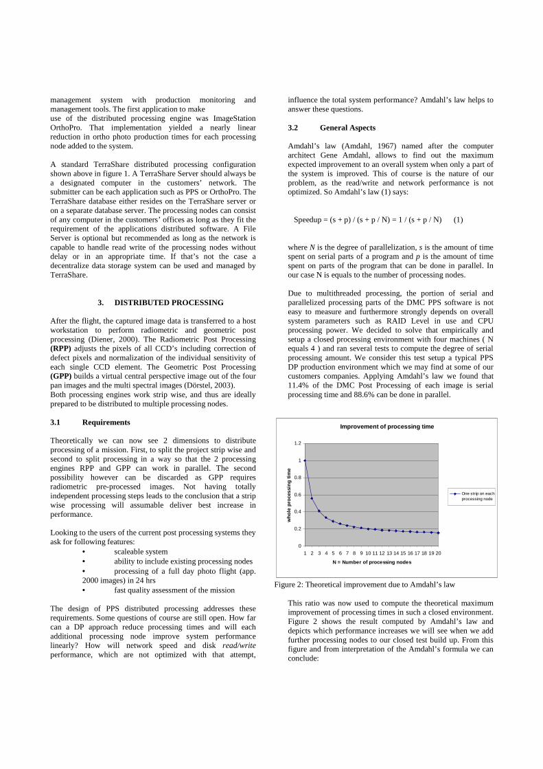
This ratio was now used to compute the theoretical maximum improvement of processing times in such a closed environment. Figure 2 shows the result computed by Amdahl’s law and depicts which performance increases we will see when we add further processing nodes to our closed test build up. From this figure and from interpretation of the Amdahl’s formula we can conclude:
Improvement of processing time
0
0.2
0.4
0.6
0.8
1
1.2
1 2 3 4 5 6 7 8 9 10 11 12 13 14 15 16 17 18 19 20
N = Number of processing nodes
wh
ole
pro
cess
ing
tim
e
One strip on eachprocessing node
Figure 2: Theoretical improvement due to Amdahl’s law
• The higher the parallel part of the system, the better is the reduction of the processing time. • Usage of more than 6 processing nodes seems not to be meaningful, as the increase in processing speed drops too much.
As the tests described above have been performed under optimum conditions not taking disk capacity, network load, unfavorable system or block configurations we should settle our expectations of a PPS DP suite a bit lower than the case investigated. 3.3 Solution Based on TerraShare Distributed Processing components a first version of PPS DP software was implemented. As TerraShare provides the complete basic communication and distribution logic for the application this was a development with low complexity. This eases development work and as just a few changes to the existing Graphical User Interface (GUI) were required it makes it very simple to operate the software The user starts the PPS software (pp.exe) on the submitting machine and selects one or more projects from the Project List. If TerraShare is installed, the user can choose if the post processing should run on the local machine or should be distributed to several or all processing nodes available (Figure 3).
Figure 3: User interface If Distributed Processing is activated, additional parameters for the job processing can be specified. Those are the “ServerType” (First Available, Input file, Output File, Specific), “ServerName”, as well as a “Job priority” (1-10) and an “Execution priority” (High, Above normal, normal, below normal, low). This few parameters can be modified in the dialogue presented in Figure 4.
Figure 4: Settings for distributed processing Hereafter the user defines the processing parameters for the project. Such can be the output format of the images (TIFF, JPEG) compression factor, pixel resolution (8/12 bit) for multiple image products (low resolution or high resolution CIR, RGB, 4 Band image, … ). Then he starts processing. The project information is now read from the PPSDatabase and the projects split automatically into the existing strips, each representing a single processing job. For each strip needed information, such as stripID and projectID are sent to the TS Submitter and all the jobs are queued to the TerraShare
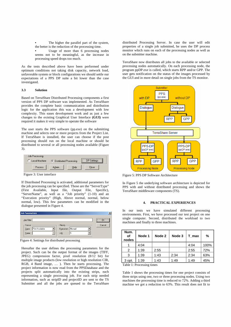
distributed Processing Server. In case the user will edit properties of a single job submitted, he uses the DP process monitor which runs on each of the processing nodes as well as on the submitter machine. TerraShare now distributes all jobs to the available or selected processing nodes automatically. On each processing node, the program ppDP.exe is called, which starts RPP and/or GPP. The user gets notification on the status of the images processed by the GUI and in more detail on single jobs from the TS monitor.
Figure 5: PPS DP Software Architecture In Figure 5 the underlying software architecture is depicted for PPS with and without distributed processing and shows the TerraShare middleware components (TS).
4. PRACTICAL EXPERIENCES In our tests we have simulated different processing environments. First, we have processed our test project on one single computer. Second, distributed the workload to two machines and finally to three machines.
Table 1: Processing times Table 1 shows the processing times for one project consists of three strips using one, two or three processing nodes. Using two machines the processing time is reduced to 72%. Adding a third machine we got a reduction to 63%. This result does not fit to
Num. of
nodes Node 1 Node 2 Node 3 T_max %
1 4:04 4:04 100%
2 1:39 2:55 2:55 72%
3 1:39 1:43 2:34 2:34 63%
3 opt. 1:39 1:43 1:49 1:49 45%

the expectations and thus needed further explanation. As we processed on processing nodes with differing performance measures this result is not surprising.
Improvement of processing time
0
0.2
0.4
0.6
0.8
1
1.2
1 2 3 4 5 6 7 8 9 10
N = Number of processing nodes
wh
ole
pro
cess
ing
tim
e
One strip on eachprocessing nodepracticalmeasurementThree similarmachines
Figure 6: Compared processing times on multiple processing nodes The processing time is always limited by the slowest machine. Figure 6 compares the optimum performance increase reachable “one strip per processing node” with the test including one slow machine “practical test” with an optimized test where the slow machine was exchanged “three similar”. In Table 1 that refers to following time measurements.
Case Presentation 3 Practical
measurements 3 opt. Three similar
In Case 3 you can see that Node 3 needs 50% longer than the other machines, so the whole processing time is limited by this CPU and can only be reduced to 63%. If this machine is replaced (Case 3 opt.) so that we process with three similar machines, the processing time can be reduced to 45%. In the second line of Table 1, the influence of the number of strips relative to the number of nodes is visible. Node 2 processed 175% of the time of Node 1, because on this machine two strips were processed. Thus we have discovered the limitations of a distributed processing environment based on a central data management concept and strip wise distribution of processing load. The best case of Amdahl is only possible if all machines have the same configuration and processing speed and the number of strips is equal to the number of processing nodes. Our example shows a worse case because of these influences. If we check the original requirement to process one full set of data of 2000 images in less than 24 hrs we need 6 processing nodes. In that case the processing time of 2.5 min. per exposure
can be reduced to 26.2% resulting in overall 22 hrs processing time. Taking into consideration that the optimum performance can not be reached at any time this prototype test has shown that the goal is reachable and that further system optimizations can contribute to stabilize this result even under marginal conditions.
5. CONCLUSION The new PPS distributed processing will reduce processing times. The amount of reduction depends on the ratio of serial processing times to the overall processing times. Shorter processing times will help the companies as in future they may be able to judge mission success earlier as the proof of requested quality and aerial triangulation results can be done within very short time after the photo flight was performed. Currently Z/I Imaging is dedicated to offer a complete automated workflow from Image Post Processing, Aerial Triangulation through DEM Generation to Ortho Photo production. Speaking of fully automated processing of image data; distributed processing can contribute to further reduce processing times, especially for the fully automated parts in the workflow. The real challenge of course is to automate the interactive data validation and compilation, and until that problem is not resolved, a fully automated ortho photo generation is just possible a low accuracy level.
6. REFERENCES Amdahl G. (1967): Validity of the Single Processor Approach to Achieving Large-Scale Computing Capabilities, AFIPS Conference Proceedings, (30), pp. 483-485. Diener S., Kiefner M., Dörstel C. (2000): Radiometric normalisation and colour composite generation of the DMC, International Archives of Photogrammetry and Remote Sensing, Vol. XXXIII, Part B1, pp. 88-92. Dörstel C., Jacobsen K., Stallmann D. (2003): DMC – photogrammetric accuracy – calibration aspects and generation of synthetic DMC images, in: Grün A., Kahmen H. (Eds.), Optical 3-D Measurement Techniques VI, Vol. I, Institute for Geodesy and Photogrammetry, ETH Zürich, 74-82. Hinz A., 1999: The Z/I Imaging Digital Modular Camera, in: Fritsch D., Spiller R. (Eds.), Photogrammetric Week ´99, Wichmann Verlag, Heidelberg, pp. 109-115. Hinz A., Dörstel C, Heier H. (2001): DMC – The Digital Sensor Technology of Z/I-Imaging, in: Fritsch D., Spiller R. (Eds.), Photogrammetric Week 2001, Wichmann, Heidelberg, pp. 93-103.