towards a fully autonomous indoor helicopter
TRANSCRIPT
Towards a Fully Autonomous Indoor Helicopter
Slawomir Grzonka, Samir Bouabdallah, Giorgio Grisetti, Wolfram Burgard and Roland Siegwart{grzonka, grisetti, burgard}@informatik.uni-freiburg.de [email protected] [email protected]
Despite the significant progress in micro and informationtechnologies and all the interest of the scientific communityin the Micro Aerial Vehicles (MAV), fully autonomousmicro-helicopters of the size of a small bird are still not avail-able. The Mesicopter group at Stanford University [1] studiedthe feasibility of a centimeter scale quadrotor. The group ofProf. Nonami at Chiba University [2] achieved a 13g semi-autonomous coaxial helicopter which is able to fly for threeminutes. Unfortunately, none of these developments combinereasonable endurance and autonomous navigation in narrowenvironments. The European project muFly [3] was born inthis context; it targets the development and implementationof a fully autonomous micro-helicopter, with a maximumspan of 20 cm and mass of 50 g. The consortium is composedof six partners; each one will provide a subsystem of theentire helicopter. One of the objectives of muFly project istointroduce low processing-power localization algorithms formicro helicopters. However, compact and lightweight indoor-localization sensors do not exist yet (unlike GPS for outdoor).Thus, CSEM research center (Switzerland) who is involvedin muFly is presently designing a miniature omni-directionalcamera [4], to be coupled with a laser source and used as a360◦ triangulation-based range finder.
This sensor and the muFly platform will be available fortesting in a couple of months. Until then, the algorithms haveto be developed and validated with another sensor and ona different flying platform. The main scope of applicationfor the helicopter are indoor environments which raisesconstraints which are not present when flying outdoors. Dueto the absence of GPS information, the robot has to relyon other on-board sensors. Furthermore, the accuracy of thepositioning system is an essential requirement for indooroperations, which is characterized by a limited safety margin(i.e. robot crossing a doorway).
In the last decade, navigation systems for autonomousflying vehicles have received an increasing attention bythe research community. Ng and colleagues [5] developedeffective control algorithms for outdoor helicopters usingreinforcement learning techniques. Haehnelet al. [6] pro-posed a 3D mapping technique for outdoor environments.For indoor navigation, Tournieret al. [7] used monocularvision in order to estimate and control the current pose ofa quadrotor. Robertset al. [8] utilized ultrasound sensorsfor control a quadrotor in an indoor environment. Recently,He et al. [9] described planning in the information space for
muFly is a STREP project under the Sixth Framework Programmeof theEuropean Commission, contract No. FP6-2005-IST-5-call 2.5.2 Micro/NanoBased Sub-Systems FP6-IST-034120.
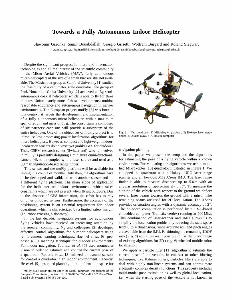
Fig. 1. Our quadrotor: 1) Mikrokopter platform, 2) Hokuyo laser rangefinder, 3) XSens IMU, 4) Gumstix computer
navigation planning.In this paper, we present the setup and the algorithms
for estimating the pose of a flying vehicle within a knownenvironment. For validating the algorithms we use a modi-fied Mikrokopter [10] quadrotor illustrated in Figure 1. Weequipped the quadrotor with a Hokuyo URG laser rangescanner and an low-cost MTi XSens IMU. The laser rangefinder is able to measure distances up to 5.6 m with anangular resolution of approximately0.35◦. To measure thealtitude of the vehicle with respect to the ground we deflectseveral laser beams towards the ground with a mirror. Theremaining beams are used for 2D localization. The XSensprovides orientation angles with a dynamic accuracy of 2◦.The on-board computation is performed by a PXA-basedembedded computer (Gumstix-verdex) running at 600 Mhz.This combination of laser-scanner and IMU allows us tosimplify the localization problem by reducing the state spacefrom 6 to 4 dimensions, since accurate roll and pitch anglesare available from the IMU. Partitioning the remaining 4DOFinto (x, y, θ) andz, makes it possible to use the broad rangeof existing algorithms for 2D (x, y, θ) wheeled mobile robotlocalization.
We apply a particle filter [11] algorithm to estimate thecurrent pose of the vehicle. In contrast to other filteringtechniques, like Kalman Filters, particles filters are abletodeal with highly non-linear systems and can approximatearbitrarily complex density functions. This property includesmulti-modal pose estimation as well as global localization,i.e., when the starting pose of the vehicle is not known in
advance. The key idea of Monte Carlo localization it toestimate the possible robot locations using a sample-basedrepresentation. Formally, the task consists in estimatingtheposteriorp(xt | z1:t,u1:t) of the current robot posext giventhe a known map of the environment, the odometry mea-surementsu1:t = 〈u1, . . . ,ut〉 and the observationsz1:t =〈z1, . . . , zt〉 made so far. In the particle filter framework, theprobability distribution about the pose of the robot at timestept is represented by a set of weighted samples{x
[j]t }. The
robustness and efficiency of this procedure strongly dependson the proposal distribution that is used to sample the newstate hypotheses in the selection step. Since our flying vehicledoes not provide reliable odometry measurements, we applyan incremental scan-matching procedure to estimate theinter-frame motion of the vehicle.
Our algorithm can be described as follows. In a first stepwe project the laser beams based on the latest roll and pitchfrom the IMU. The projected beams are then divided into twoparts namely the beams for height estimation and the beamsfor 2D (x, y, θ) localization. We then perform incrementalscan-matching by considering the localization beams. In thisway we get an estimate of the inter-frame motion whichis used in the prediction step of the particle filter. Themeasurement update utilizes the current (projected) laserbeams and a likelihood-field map of the environment tocalculate the individual weights of the particles.
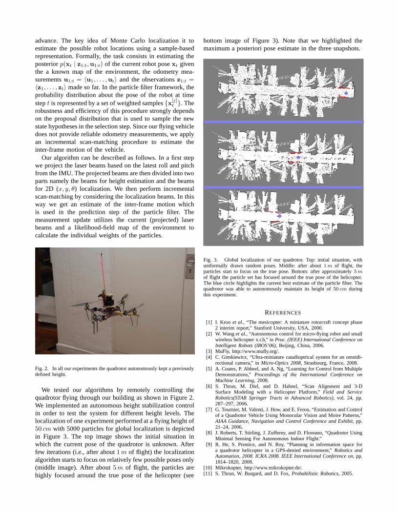
Fig. 2. In all our experiments the quadrotor autonomously kept a previouslydefined height.
We tested our algorithms by remotely controlling thequadrotor flying through our building as shown in Figure 2.We implemented an autonomous height stabilization controlin order to test the system for different height levels. Thelocalization of one experiment performed at a flying height of50 cm with 5000 particles for global localization is depictedin Figure 3. The top image shows the initial situation inwhich the current pose of the quadrotor is unknown. Afterfew iterations (i.e., after about1 m of flight) the localizationalgorithm starts to focus on relatively few possible poses only(middle image). After about5 m of flight, the particles arehighly focused around the true pose of the helicopter (see
bottom image of Figure 3). Note that we highlighted themaximum a posteriori pose estimate in the three snapshots.
Fig. 3. Global localization of our quadrotor. Top: initial situation, withuniformally drawn random poses. Middle: after about1 m of flight, theparticles start to focus on the true pose. Bottom: after approximately 5 m
of flight the particle set has focused around the true pose of the helicopter.The blue circle highlights the current best estimate of the particle filter. Thequadrotor was able to autonomously maintain its height of50 cm duringthis experiment.
REFERENCES
[1] I. Kroo et al., “The mesicopter: A miniature rotorcraft concept phase2 interim report,” Stanford University, USA, 2000.
[2] W. Wanget al., “Autonomous control for micro-flying robot and smallwireless helicopter x.r.b,” inProc. (IEEE) International Conference onIntelligent Robots (IROS’06), Beijing, China, 2006.
[3] MuFly, http://www.mufly.org/.[4] C. Gimkiewicz, “Ultra-miniature catadioptrical system for an omnidi-
rectional camera,” inMicro-Optics 2008, Strasbourg, France, 2008.[5] A. Coates, P. Abbeel, and A. Ng, “Learning for Control from Multiple
Demonstrations,”Proceedings of the International Conference onMachine Learning, 2008.
[6] S. Thrun, M. Diel, and D. Hahnel, “Scan Alignment and 3-DSurface Modeling with a Helicopter Platform,”Field and ServiceRobotics(STAR Springer Tracts in Advanced Robotics), vol. 24, pp.287–297, 2006.
[7] G. Tournier, M. Valenti, J. How, and E. Feron, “Estimation and Controlof a Quadrotor Vehicle Using Monocular Vision and Moire Patterns,”AIAA Guidance, Navigation and Control Conference and Exhibit, pp.21–24, 2006.
[8] J. Roberts, T. Stirling, J. Zufferey, and D. Floreano, “Quadrotor UsingMinimal Sensing For Autonomous Indoor Flight.”
[9] R. He, S. Prentice, and N. Roy, “Planning in information space fora quadrotor helicopter in a GPS-denied environment,”Robotics andAutomation, 2008. ICRA 2008. IEEE International Conference on, pp.1814–1820, 2008.
[10] Mikrokopter, http://www.mikrokopter.de/.[11] S. Thrun, W. Burgard, and D. Fox,Probabilistic Robotics, 2005.