total recall - madbeanpedals recall.pdf · the total recall is a clone of the big box dmm which ......
TRANSCRIPT
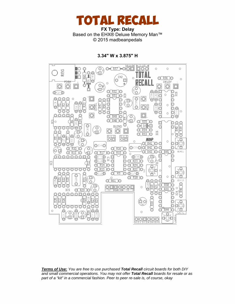
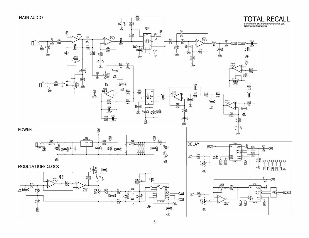
Total Recall FX Type: Delay
Based on the EHX® Deluxe Memory Man™ © 2015 madbeanpedals
3.34" W x 3.875" H
Terms of Use: You are free to use purchased Total Recall circuit boards for both DIY and small commercial operations. You may not offer Total Recall boards for resale or as part of a “kit” in a commercial fashion. Peer to peer re-sale is, of course, okay
2
3
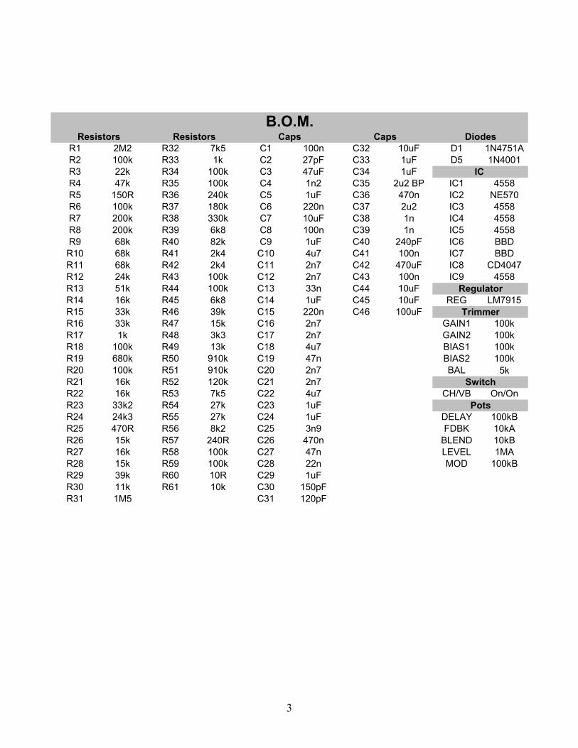
R1 2M2 R32 7k5 C1 100n C32 10uF D1 1N4751AR2 100k R33 1k C2 27pF C33 1uF D5 1N4001R3 22k R34 100k C3 47uF C34 1uFR4 47k R35 100k C4 1n2 C35 2u2 BP IC1 4558R5 150R R36 240k C5 1uF C36 470n IC2 NE570R6 100k R37 180k C6 220n C37 2u2 IC3 4558R7 200k R38 330k C7 10uF C38 1n IC4 4558R8 200k R39 6k8 C8 100n C39 1n IC5 4558R9 68k R40 82k C9 1uF C40 240pF IC6 BBDR10 68k R41 2k4 C10 4u7 C41 100n IC7 BBDR11 68k R42 2k4 C11 2n7 C42 470uF IC8 CD4047R12 24k R43 100k C12 2n7 C43 100n IC9 4558R13 51k R44 100k C13 33n C44 10uFR14 16k R45 6k8 C14 1uF C45 10uF REG LM7915R15 33k R46 39k C15 220n C46 100uFR16 33k R47 15k C16 2n7 GAIN1 100kR17 1k R48 3k3 C17 2n7 GAIN2 100kR18 100k R49 13k C18 4u7 BIAS1 100kR19 680k R50 910k C19 47n BIAS2 100kR20 100k R51 910k C20 2n7 BAL 5kR21 16k R52 120k C21 2n7R22 16k R53 7k5 C22 4u7 CH/VB On/OnR23 33k2 R54 27k C23 1uFR24 24k3 R55 27k C24 1uF DELAY 100kBR25 470R R56 8k2 C25 3n9 FDBK 10kAR26 15k R57 240R C26 470n BLEND 10kBR27 16k R58 100k C27 47n LEVEL 1MAR28 15k R59 100k C28 22n MOD 100kBR29 39k R60 10R C29 1uFR30 11k R61 10k C30 150pFR31 1M5 C31 120pF
Caps Caps
Switch
Pots
B.O.M.Diodes
IC
Regulator
Trimmer
Resistors Resistors
4
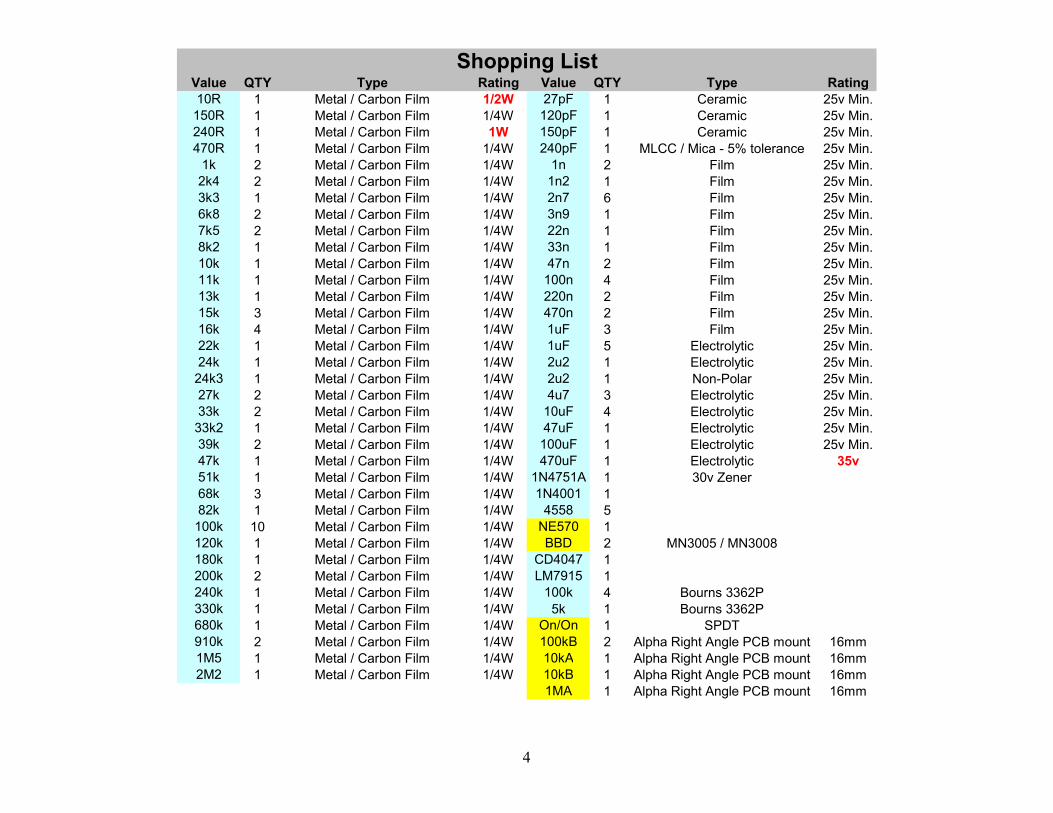
Value QTY Type Rating Value QTY Type Rating10R 1 Metal / Carbon Film 1/2W 27pF 1 Ceramic 25v Min.150R 1 Metal / Carbon Film 1/4W 120pF 1 Ceramic 25v Min.240R 1 Metal / Carbon Film 1W 150pF 1 Ceramic 25v Min.470R 1 Metal / Carbon Film 1/4W 240pF 1 MLCC / Mica - 5% tolerance 25v Min.
1k 2 Metal / Carbon Film 1/4W 1n 2 Film 25v Min.2k4 2 Metal / Carbon Film 1/4W 1n2 1 Film 25v Min.3k3 1 Metal / Carbon Film 1/4W 2n7 6 Film 25v Min.6k8 2 Metal / Carbon Film 1/4W 3n9 1 Film 25v Min.7k5 2 Metal / Carbon Film 1/4W 22n 1 Film 25v Min.8k2 1 Metal / Carbon Film 1/4W 33n 1 Film 25v Min.10k 1 Metal / Carbon Film 1/4W 47n 2 Film 25v Min.11k 1 Metal / Carbon Film 1/4W 100n 4 Film 25v Min.13k 1 Metal / Carbon Film 1/4W 220n 2 Film 25v Min.15k 3 Metal / Carbon Film 1/4W 470n 2 Film 25v Min.16k 4 Metal / Carbon Film 1/4W 1uF 3 Film 25v Min.22k 1 Metal / Carbon Film 1/4W 1uF 5 Electrolytic 25v Min.24k 1 Metal / Carbon Film 1/4W 2u2 1 Electrolytic 25v Min.24k3 1 Metal / Carbon Film 1/4W 2u2 1 Non-Polar 25v Min.27k 2 Metal / Carbon Film 1/4W 4u7 3 Electrolytic 25v Min.33k 2 Metal / Carbon Film 1/4W 10uF 4 Electrolytic 25v Min.33k2 1 Metal / Carbon Film 1/4W 47uF 1 Electrolytic 25v Min.39k 2 Metal / Carbon Film 1/4W 100uF 1 Electrolytic 25v Min.47k 1 Metal / Carbon Film 1/4W 470uF 1 Electrolytic 35v51k 1 Metal / Carbon Film 1/4W 1N4751A 1 30v Zener68k 3 Metal / Carbon Film 1/4W 1N4001 182k 1 Metal / Carbon Film 1/4W 4558 5100k 10 Metal / Carbon Film 1/4W NE570 1120k 1 Metal / Carbon Film 1/4W BBD 2 MN3005 / MN3008180k 1 Metal / Carbon Film 1/4W CD4047 1200k 2 Metal / Carbon Film 1/4W LM7915 1240k 1 Metal / Carbon Film 1/4W 100k 4 Bourns 3362P330k 1 Metal / Carbon Film 1/4W 5k 1 Bourns 3362P680k 1 Metal / Carbon Film 1/4W On/On 1 SPDT910k 2 Metal / Carbon Film 1/4W 100kB 2 Alpha Right Angle PCB mount 16mm1M5 1 Metal / Carbon Film 1/4W 10kA 1 Alpha Right Angle PCB mount 16mm2M2 1 Metal / Carbon Film 1/4W 10kB 1 Alpha Right Angle PCB mount 16mm
1MA 1 Alpha Right Angle PCB mount 16mm
Shopping List
5
6
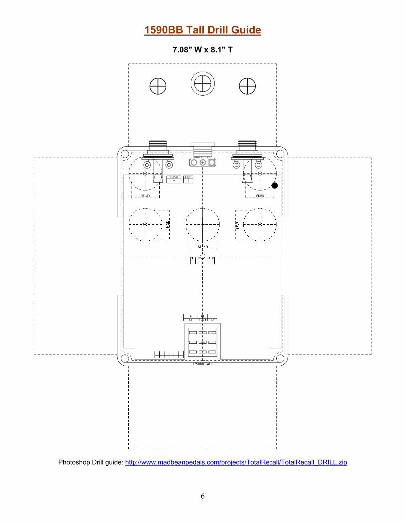
1590BB Tall Drill Guide
7.08" W x 8.1" T
Photoshop Drill guide: http://www.madbeanpedals.com/projects/TotalRecall/TotalRecall_DRILL.zip
7
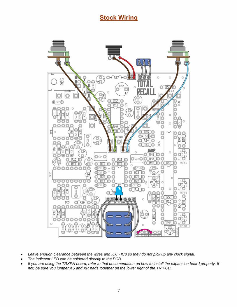
Stock Wiring
Leave enough clearance between the wires and IC6 - IC8 so they do not pick up any clock signal. The indicator LED can be soldered directly to the PCB. If you are using the TRXPN board, refer to that documentation on how to install the expansion board properly. If
not, be sure you jumper XS and XR pads together on the lower right of the TR PCB.
8
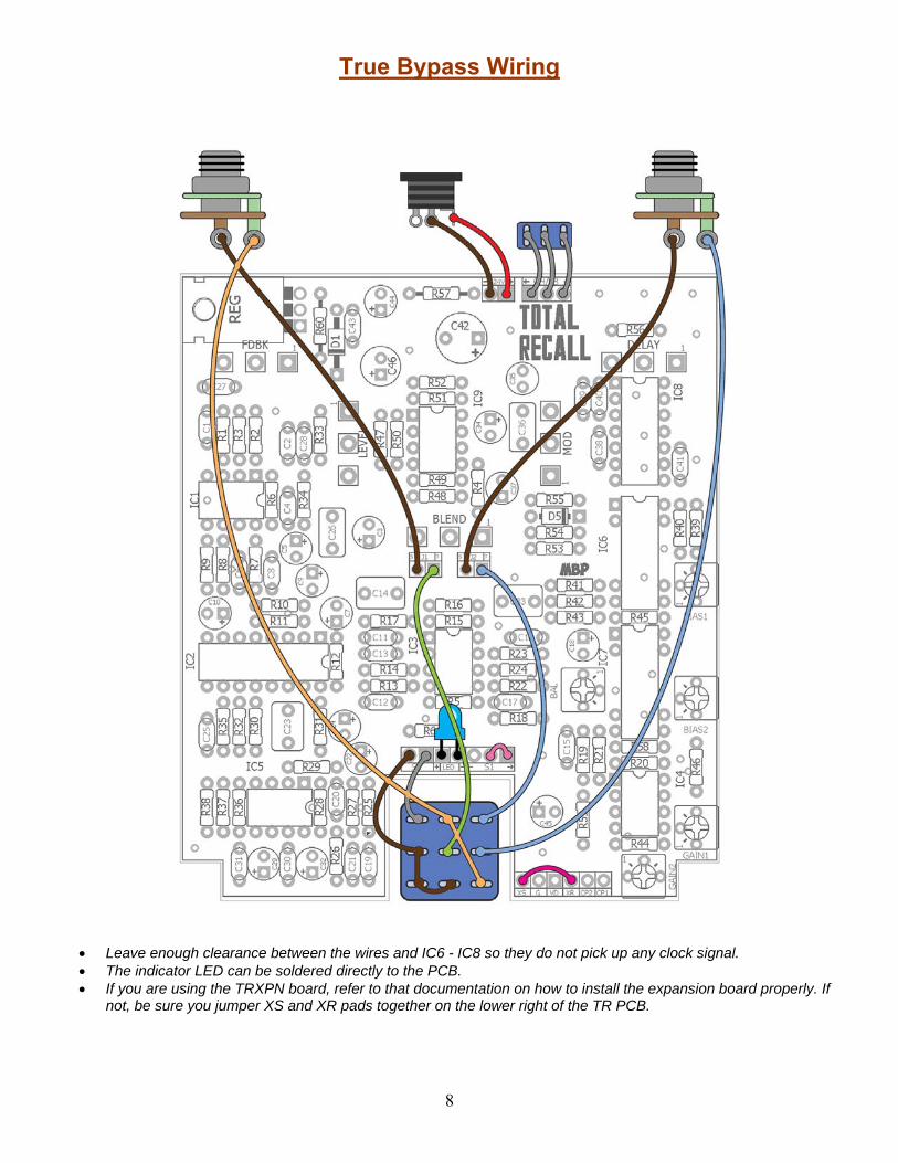
True Bypass Wiring
Leave enough clearance between the wires and IC6 - IC8 so they do not pick up any clock signal. The indicator LED can be soldered directly to the PCB. If you are using the TRXPN board, refer to that documentation on how to install the expansion board properly. If
not, be sure you jumper XS and XR pads together on the lower right of the TR PCB.
9
At long last, the vintage Memory Man™ project is here! The Total Recall is a clone of the big box DMM which allows you to use either two MN3005 or four MN3008 (if you include the optional expansion board; the TRXPN). With the recent release of the Xvive MN3005 clones this project is suddenly much more viable for builders not lucky enough to get their hands on NOS MN3005 chips (which can go for as much as $40 a piece these days, if you are lucky to get a non-counterfeit one). The good news is that the Xvive chips seem to work very well in the Total Recall. Tests were done comparing them to 2xMN3005 (NOS) and 4xMN3008 (NOS) and they performed very comparable (at least with the two Xvive chips I have on hand). While I won't get into any machinations on precision MOJO between the NOS and new production chips, I am satisfied that the Xvive are fine for this project and the end result sounds great. Perhaps they are even slightly cleaner in output (which is not terribly surprising when you compare recently manufactured IC's with those made 30 years ago).
Some important notes before considering this project
It's hard. Not the hardest DIY project ever, but pretty challenging. You need to have enough patience to work through the building AND setting it up properly. This means NO BOXING BEFORE ROCKING. You must test this project adequately with a multi-meter AND audio probe before wiring it up in an enclosure. There will be no mercy for tech threads started on the forum by those who ignore this :)
It's positive ground and it requires a wall-wart. There's no getting around it. If you want the true vintage DMM, you
have to design it to use a wall-wart or AC power plus a transformer. I use, and recommend, an actual EHX 24v supply. It's not too expensive and it works perfectly for the project. And with it, my two builds are dead quiet. You can get the power supply here: http://www.amazon.com/Electro-Harmonix-US24DC-100-24V-Power-Supply/dp/B0042RHT4M. You should be able to use an 18v supply instead of the 24v one listed above, although this has not been tested. You will need to do a couple things: 1) Lower the value of R57 from 240R 1W to something like 22R 1W, and 2) make sure you know what the polarity of your 18v power supply is before hooking it up to the TR PCB!
It's expensive. Granted, building your own is still way cheaper than buying a vintage unit, but all in all you can
expect to drop $100 or more on this project including the PCBs, power supply and two BBDs. The Total Recall does have some differences with the DMM. I use 1uF film caps instead of non-polar electrolytic
(as a matter of personal preference), the "overload LED" circuitry is not used due to space limitations and finally the GAIN1 trimmer is located between BBD stages 3 and 4 instead of 2 & 3 (if using the TRXPN board only, otherwise it is between the two BBD stages when using two MN3005). This last one is the most important. While it does not seem to pose any limitations when using four MN3008, I would not recommend plugging in four MN3005 (as some might be tempted to do) to get 1 second of delay instead of 550ms. Four MN3005 should work for all four BBD spots, but it has not been tested and the extra delay time may prove problematic for the gain recovery.
XVIVE MN3005: http://smallbear-electronics.mybigcommerce.com/mn3005-re-makes-xvive-audio/
Controls
DELAY: Total delay time from slap-back to approximately 550ms. FDBK: The total number of repeats from one to many to self-oscillation. LEVEL: The input gain of the circuit. This control can create mild overdrive when turned up. BLEND: The dry/wet ratio of guitar and delay. MOD: The depth of modulation applied to the delay signal. The modulation rate is fixed. CH/VB: This switches between chorus and vibrato type modulation.
Biasing Controls BIAS1, 2: These trimmers set the input biasing of the BBD chips. GAIN1, 2: These trimmers set the gain recovery after BBD1 and BBD2. BAL: This trimmer balances the two outputs of the second BBD.
10
Wiring You can wire the Total Recall in either stock or true-bypass fashion. In the stock wiring, the LEVEL control is always active and can be used to boost the bypass signal. Personally, I like this option as the circuit's higher voltage provides a nice clean boost at low LEVEL settings up to a mild overdrive at high settings. If you are a true-bypass purist, use the second wiring diagram. This completely removes the circuit from the bypass mode.
Build Notes Take your time and build it right the FIRST time! There are a lot of parts here and the attention and focus you employ in soldering and construction will save you loads of headaches later on.
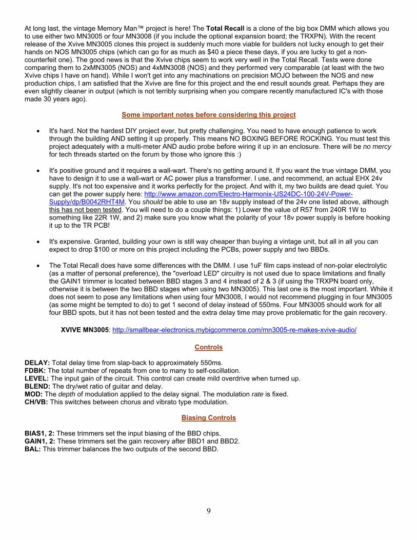
Before doing any voltage tests, make sure you have wired the power correctly. Remember that this is a positive ground circuit! The illustration below shows how the typical DC jack is wired with the EHX power supply for the correct polarity. If you are using a different jack or power supply, plug the PS into your DC jack before wiring it to the PCB and use your multi-meter to verify which lug on the jack is negative DC. Once you have verified polarity on the jack, hook up the PCB to the power supply. Now check the LM7915 regulator to verify that you are getting about -15v output. Once that is complete, disconnect the power and start loading in the ICs.
EHX power supply wiring for positive ground.
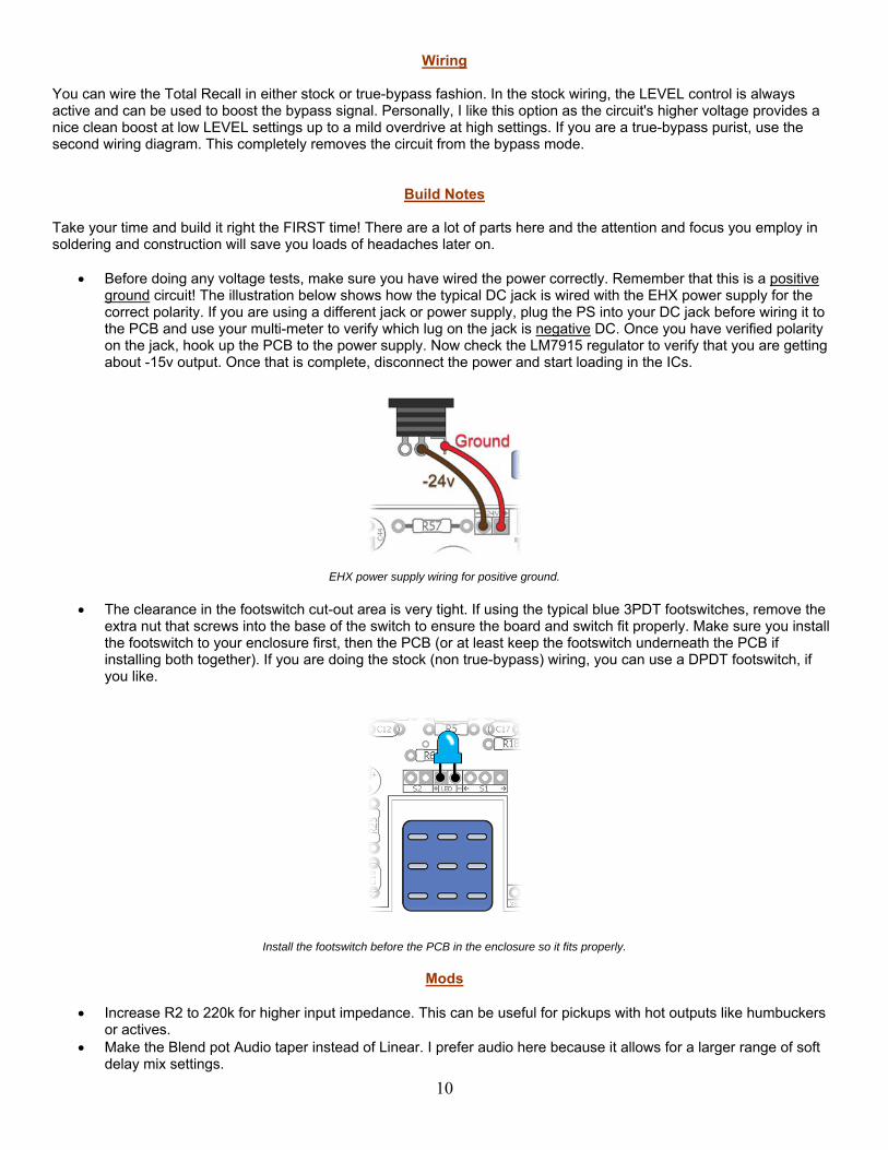
The clearance in the footswitch cut-out area is very tight. If using the typical blue 3PDT footswitches, remove the extra nut that screws into the base of the switch to ensure the board and switch fit properly. Make sure you install the footswitch to your enclosure first, then the PCB (or at least keep the footswitch underneath the PCB if installing both together). If you are doing the stock (non true-bypass) wiring, you can use a DPDT footswitch, if you like.
Install the footswitch before the PCB in the enclosure so it fits properly.
Mods
Increase R2 to 220k for higher input impedance. This can be useful for pickups with hot outputs like humbuckers or actives.
Make the Blend pot Audio taper instead of Linear. I prefer audio here because it allows for a larger range of soft delay mix settings.
11
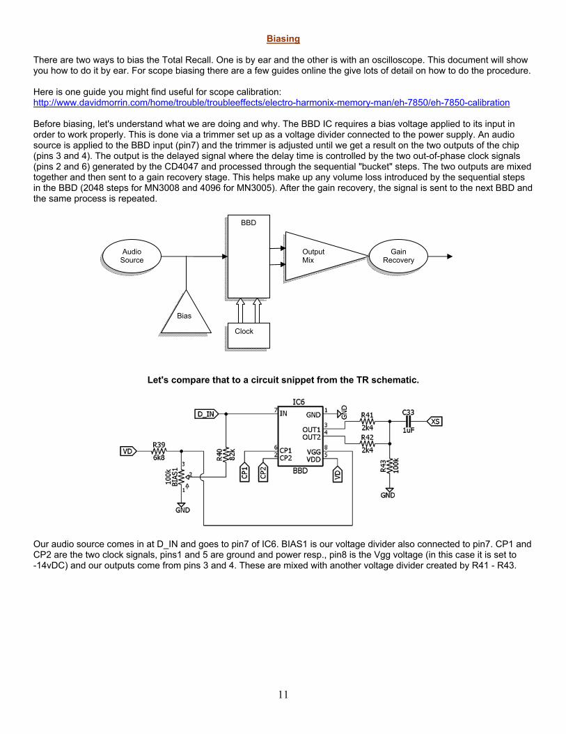
Biasing There are two ways to bias the Total Recall. One is by ear and the other is with an oscilloscope. This document will show you how to do it by ear. For scope biasing there are a few guides online the give lots of detail on how to do the procedure. Here is one guide you might find useful for scope calibration: http://www.davidmorrin.com/home/trouble/troubleeffects/electro-harmonix-memory-man/eh-7850/eh-7850-calibration Before biasing, let's understand what we are doing and why. The BBD IC requires a bias voltage applied to its input in order to work properly. This is done via a trimmer set up as a voltage divider connected to the power supply. An audio source is applied to the BBD input (pin7) and the trimmer is adjusted until we get a result on the two outputs of the chip (pins 3 and 4). The output is the delayed signal where the delay time is controlled by the two out-of-phase clock signals (pins 2 and 6) generated by the CD4047 and processed through the sequential "bucket" steps. The two outputs are mixed together and then sent to a gain recovery stage. This helps make up any volume loss introduced by the sequential steps in the BBD (2048 steps for MN3008 and 4096 for MN3005). After the gain recovery, the signal is sent to the next BBD and the same process is repeated.
Let's compare that to a circuit snippet from the TR schematic.
Our audio source comes in at D_IN and goes to pin7 of IC6. BIAS1 is our voltage divider also connected to pin7. CP1 and CP2 are the two clock signals, pins1 and 5 are ground and power resp., pin8 is the Vgg voltage (in this case it is set to -14vDC) and our outputs come from pins 3 and 4. These are mixed with another voltage divider created by R41 - R43.
Audio Source
Bias
BBD
Clock
Output Mix
Gain Recovery
12
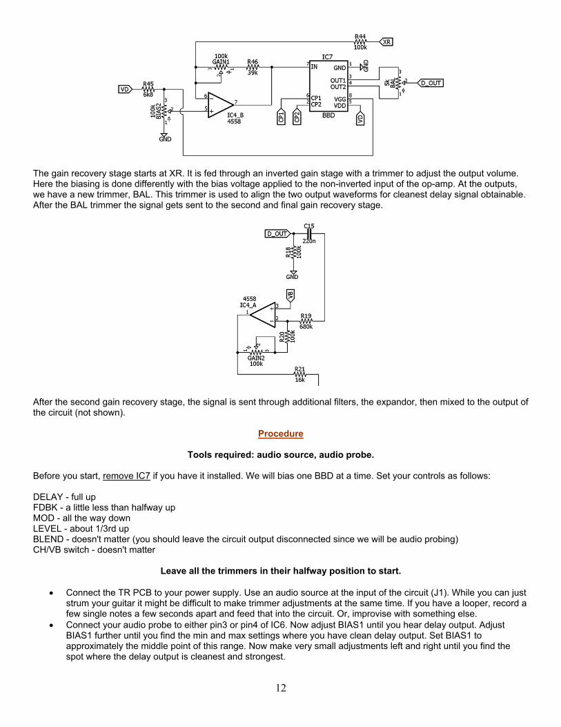
The gain recovery stage starts at XR. It is fed through an inverted gain stage with a trimmer to adjust the output volume. Here the biasing is done differently with the bias voltage applied to the non-inverted input of the op-amp. At the outputs, we have a new trimmer, BAL. This trimmer is used to align the two output waveforms for cleanest delay signal obtainable. After the BAL trimmer the signal gets sent to the second and final gain recovery stage.
After the second gain recovery stage, the signal is sent through additional filters, the expandor, then mixed to the output of the circuit (not shown).
Procedure
Tools required: audio source, audio probe. Before you start, remove IC7 if you have it installed. We will bias one BBD at a time. Set your controls as follows: DELAY - full up FDBK - a little less than halfway up MOD - all the way down LEVEL - about 1/3rd up BLEND - doesn't matter (you should leave the circuit output disconnected since we will be audio probing) CH/VB switch - doesn't matter
Leave all the trimmers in their halfway position to start.
Connect the TR PCB to your power supply. Use an audio source at the input of the circuit (J1). While you can just strum your guitar it might be difficult to make trimmer adjustments at the same time. If you have a looper, record a few single notes a few seconds apart and feed that into the circuit. Or, improvise with something else.
Connect your audio probe to either pin3 or pin4 of IC6. Now adjust BIAS1 until you hear delay output. Adjust BIAS1 further until you find the min and max settings where you have clean delay output. Set BIAS1 to approximately the middle point of this range. Now make very small adjustments left and right until you find the spot where the delay output is cleanest and strongest.

13
Now connect your audio probe to pin7 of IC4_B. Adjust GAIN1 until the volume output is approximately the same as the volume input on pin7 of IC6 (this balances the signal volumes between the two BBDs).
Disconnect the power supply from the circuit and install IC7. Reconnect the power supply. Connect your audio probe to pin3 or 4 of IC7. Do the same type of adjustment to BIAS2 to get clean delay output. Re-connect your audio probe to pin7 of IC4_B. Make any adjustments needed to GAIN1 to reach the same
volume output you had before. This part is a bit of fine tuning between GAIN1 and BIAS2 to get the optimal result. Leave the BAL trimmer in the middle position. Connect your audio probe to pin1 of IC4_A. Adjust the GAIN2
trimmer until the output is the same or slightly above the volume input of pin7 on IC6. You are done!
If you are using the BBD expansion board, refer to that documentation on how to do this procedure with four BBDs. It is generally the same thing with a few added steps.
Mouser Cart For convenience, I have created a cart in Mouser that includes most of the items in the BOM. All the items highlighted in blue are in the cart in the correct quantities. Items in yellow are not included in the cart. Caveat: I have not personally ordered this cart. It was made using my "best guess" on the parts I would order for this project. http://www.mouser.com/ProjectManager/ProjectDetail.aspx?AccessID=16a26046e1 Also, this cart does not include the quantities needed for the TRXPN board. However, those parts and values are already listed in the Mouser cart. Simply put in the additional quantities needed for the resistors, caps and trimmers for the TRXPN board.
14
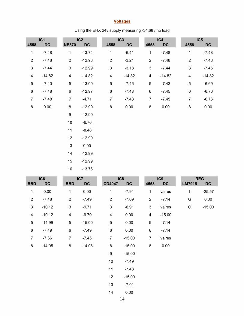
Voltages
Using the EHX 24v supply measuring -34.68 / no load
4558 DC NE570 DC 4558 DC 4558 DC 4558 DC
1 -7.48 1 -13.74 1 -6.41 1 -7.48 1 -7.48
2 -7.48 2 -12.98 2 -3.21 2 -7.48 2 -7.48
3 -7.44 3 -12.99 3 -3.18 3 -7.44 3 -7.46
4 -14.82 4 -14.82 4 -14.82 4 -14.82 4 -14.82
5 -7.40 5 -13.00 5 -7.46 5 -7.43 5 -6.69
6 -7.48 6 -12.97 6 -7.48 6 -7.45 6 -6.76
7 -7.48 7 -4.71 7 -7.48 7 -7.45 7 -6.76
8 0.00 8 -12.99 8 0.00 8 0.00 8 0.00
9 -12.99
10 -6.76
11 -8.48
12 -12.99
13 0.00
14 -12.99
15 -12.99
16 -13.76
BBD DC BBD DC CD4047 DC 4558 DC LM7915 DC
1 0.00 1 0.00 1 -7.94 1 vaires I -25.57
2 -7.48 2 -7.49 2 -7.09 2 -7.14 G 0.00
3 -10.12 3 -9.71 3 -6.91 3 vaires O -15.00
4 -10.12 4 -9.70 4 0.00 4 -15.00
5 -14.99 5 -15.00 5 0.00 5 -7.14
6 -7.49 6 -7.49 6 0.00 6 -7.14
7 -7.66 7 -7.45 7 -15.00 7 vaires
8 -14.05 8 -14.06 8 -15.00 8 0.00
9 -15.00
10 -7.49
11 -7.48
12 -15.00
13 -7.01
14 0.00
IC5
IC6 IC7 IC8 IC9 REG
IC1 IC2 IC3 IC4
15