toshiba personal computer maintenance...
TRANSCRIPT
Toshiba Personal Computer
Satellite A70
Maintenance Manual
TOSHIBA CORPORATION
ii Satellite A70 Maintenance Manual
Copyright
© 2004 by Toshiba Corporation. All rights reserved. Under the copyright laws, this manual cannot be reproduced in any form without the prior written permission of Toshiba. No patent liability is assumed with respect to the use of the information contained herein.
Toshiba Personal Computer Satellite SATELLITE A70 Maintenance Manual
First edition September 2004
Disclaimer
The information presented in this manual has been reviewed and validated for accuracy. The included set of instructions and descriptions are accurate for the A70 Series at the time of this manual's production. However, succeeding computers and manuals are subject to change without notice. Therefore, Toshiba assumes no liability for damages incurred directly or indirectly from errors, omissions, or discrepancies between any succeeding product and this manual.
Trademarks
IBM is a registered trademark, and OS/2 and PS/2 are trademarks of IBM Corporation. Microsoft, MS-DOS, Windows, DirectSound and DirectMusic are registered trademarks of Microsoft Corporation. Intel and Pentium are registered trademarks, and SpeedStep is a trademark of Intel Corporation. Sound Blaster is a registered trademark of Creative Technology Ltd. Centronics is a registered trademark of Centronics Data Computer Corporation. Photo CD is a trademark of Eastman Kodak. All other properties are trademarks or registered trademarks of their respective holders.
Satellite A70 Maintenance Manual iii
Preface
This maintenance manual describes how to perform hardware service maintenance for the Toshiba Personal Computer Satellite SATELLITE A70/A75, referred to as the A70 Series in this manual.
The procedures described in this manual are intended to help service technicians isolate faulty Field Replaceable Units (FRUs) and replace them in the field.
SAFETY PRECAUTIONS
Four types of messages are used in this manual to bring important information to your attention. Each of these messages will be italicized and identified as shown below.
DANGER: “Danger” indicates the existence of a hazard that could result in death or serious bodily injury if the safety instruction is not observed.
WARNING: “Warning” indicates the existence of a hazard that could result in bodily injury if the safety instruction is not observed.
CAUTION: “Caution” indicates the existence of a hazard that could result in property damage if the safety instruction is not observed.
NOTE: “Note” contains general information that relates to your safe maintenance service.
Improper repair of the computer may result in safety hazards. Toshiba requires service technicians and authorized dealers or service providers to ensure the following safety precautions are adhered to strictly.
Be sure to fasten screws securely with the right screwdriver. If a screw is not fully fastened, it could come loose, creating a danger of a short circuit, which could cause overheating, smoke or fire.
If you replace the battery pack or RTC battery, be sure to use only the same model battery or an equivalent battery recommended by Toshiba. Installation of the wrong battery can cause the battery to explode.
iv Satellite A70 Maintenance Manual
The manual is divided into the following parts:
Chapter 1 Hardware Overview describes the A70 Series system unit and each FRU.
Chapter 2 Troubleshooting Procedures explains how to diagnose and resolve FRU problems.
Chapter 3 Test and Diagnostics describes how to perform test and diagnostic operations for maintenance service.
Chapter 4 Replacement Procedures describes the removal and replacement of the FRUs.
Appendices The appendices describe the following:
Handling the LCD module Board layout Pin assignments Keyboard scan/character codes Key layout Screw torque list Reliability
Satellite A70 Maintenance Manual v
Conventions
This manual uses the following formats to describe, identify, and highlight terms and operating procedures.
Acronyms
On the first appearance and whenever necessary for clarification acronyms are enclosed in parentheses following their definition. For example:
Read Only Memory (ROM)
Keys
Keys are used in the text to describe many operations. The key top symbol as it appears on the keyboard is printed in boldface type.
Key operation
Some operations require you to simultaneously use two or more keys. We identify such operations by the key top symbols separated by a plus (+) sign. For example, Ctrl + Pause (Break) means you must hold down Ctrl and at the same time press Pause (Break). If three keys are used, hold down the first two and at the same time press the third.
User input
Text that you are instructed to type in is shown in the boldface type below:
DISKCOPY A: B:
The display
Text generated by the computer that appears on its display is presented in the type face below:
Format complete System transferred

vi Satellite A70 Maintenance Manual
Satellite A70 Maintenance Manual vii
Table of Contents
Chapter 1 Hardware Overview
1.1 Features ............................................................................................................................ 1-1
1.2 System Unit...................................................................................................................... 1-5
1.3 2.5-inch Hard Disk Drive................................................................................................. 1-9
1.4 Removable Drives.......................................................................................................... 1-10
1.5 Power Supply ................................................................................................................. 1-16
1.6 Batteries ......................................................................................................................... 1-18
Chapter 2 Troubleshooting Procedures
2.1 Troubleshooting Introduction .......................................................................................... 2-1
2.2 Troubleshooting Flowchart.............................................................................................. 2-2
2.3 Power Supply Troubleshooting ....................................................................................... 2-7
2.4 Display Troubleshooting................................................................................................ 2-12
2.5 Keyboard Troubleshooting ............................................................................................ 2-15
2.6 External USB Devices Troubleshooting........................................................................ 2-17
2.7 TV-Out Failure Troubleshooting ................................................................................... 2-19
2.8 Printer Port Troubleshooting ......................................................................................... 2-21
2.9 TouchPad Troubleshooting............................................................................................ 2-23
2.10 Speaker Troubleshooting ............................................................................................... 2-25
2.11 Optical Drive Troubleshooting ...................................................................................... 2-27
2.12 Modem Troubleshooting................................................................................................ 2-30
2.13 PCMCIA Troubleshooting............................................................................................. 2-32
2.14 IEEE 1394 Troubleshooting .......................................................................................... 2-34
2.15 Wireless LAN Troubleshooting..................................................................................... 2-36
viii Satellite A70 Maintenance Manual
Chapter 3 Tests and Diagnostics
3.1 The Diagnostic Test .........................................................................................................3-1
3.2 Executing the Diagnostic Test..........................................................................................3-2
3.3 Config Check Test............................................................................................................3-6
3.4 DMI Check Test ...............................................................................................................3-7
3.5 PIO Loopback Test...........................................................................................................3-8
3.6 IEEE 1394 Test ................................................................................................................3-9
3.7 Speaker Audio Test ........................................................................................................3-10
3.8 Fan ON/OFF Test ...........................................................................................................3-11
3.9 Main Battery Charge Test ..............................................................................................3-12
3.10 FDD Test ........................................................................................................................3-13
3.11 CD-ROM Test ................................................................................................................3-14
3.12 Keyboard Test ................................................................................................................3-15
3.13 Mouse (Pad) Test ...........................................................................................................3-17
3.14 LCD Pixels Mode Test ...................................................................................................3-19
3.15 Lid Switch Test ..............................................................................................................3-20
3.16 HDD R/W Test ...............................................................................................................3-21
3.17 LAN Test ........................................................................................................................3-23
3.18 RTC Test ........................................................................................................................3-25
3.19 CD Control Button Test .................................................................................................3-26
Satellite A70 Maintenance Manual ix
Chapter 4 Replacement Procedures
4.1 General............................................................................................................................. 4-1
4.2 Battery.............................................................................................................................. 4-7
4.3 PC Card............................................................................................................................ 4-9
4.4 HDD............................................................................................................................... 4-11
4.5 Optical Drive Module .................................................................................................... 4-13
4.6 Optical Drive.................................................................................................................. 4-15
4.7 Wireless LAN Unit ........................................................................................................ 4-17
4.8 Expansion Memory........................................................................................................ 4-20
4.9 Keyboard........................................................................................................................ 4-23
4.10 Modem ........................................................................................................................... 4-26
4.11 Display Assembly .......................................................................................................... 4-28
4.12 Touch Cover................................................................................................................... 4-31
4.13 Touch Pad ...................................................................................................................... 4-34
4.14 Speakers ......................................................................................................................... 4-36
4.15 System Board ................................................................................................................. 4-37
4.16 Fan, Heat Sink, & CPU.................................................................................................. 4-39
4.17 Display Mask ................................................................................................................. 4-42
4.18 LCD Module .................................................................................................................. 4-44
4.19 FL Inverter Board .......................................................................................................... 4-47
x Satellite A70 Maintenance Manual
Appendices
Appendix A Handling the LCD Module..................................................................................A-1
Appendix B Board Layout.......................................................................................................B-1
Appendix C Pin Assignments ..................................................................................................C-1
Appendix D Keyboard Scan/Character Codes.........................................................................D-1
Appendix E Key Layout .......................................................................................................... E-1
Appendix F Series Screw Torque List .................................................................................... F-1
Appendix G Reliability ............................................................................................................G-1

Chapter 1 Hardware Overview 1

1 Hardware Overview
1-ii Satellite A70 Series Maintenance Manual
1 Hardware Overview
Chapter 1 Contents
1.1 Features ...................................................................................................................... 1-1
1.2 System Unit................................................................................................................ 1-5
1.3 2.5-inch Hard Disk Drive........................................................................................... 1-9
1.4 Removable Drives.................................................................................................... 1-10
1.4.1 DVD-R/-RW Drive ................................................................................... 1-10
1.4.2 DVD-ROM Drive...................................................................................... 1-12
1.4.3 DVD+-R/DVD+-RW Drive ...................................................................... 1-14
1.4.4 DVD Super Multi Drive............................................................................ 1-15
1.5 Power Supply ........................................................................................................... 1-16
1.6 Batteries ................................................................................................................... 1-18
1.6.1 Main Battery.............................................................................................. 1-18
1.6.2 RTC battery ............................................................................................... 1-19
Satellite A70 Series Maintenance Manual 1-iii

1 Hardware Overview
1-iv Satellite A70 Series Maintenance Manual

1.1 Features 1 Hardware Overview
1.1 Features
The Satellite A70 Series Personal Computer uses extensive Large Scale Integration (LSI), and Complementary Metal-Oxide Semiconductor (CMOS) technology extensively to provide compact size, minimum weight and high reliability. This computer incorporates the following features and benefits: CPU
• Intel® Celeron® Processor up to 2.8 GHz • Mobile Intel® Pentium® 4 Processor up to 3.06GHz • Mobile Intel® Pentium® 4 Processor up to 3.2GHz supporting HT Technology • Mobile Intel® Pentium® 4 Processor up to 538 or higher supporting HT Technology
• Micro FC-PGA package CPU Chipset
• ATI Mobility RadeonTM 9000IGP • ATI IXP150 • ENE KB910 for Keyboard Controller, Battery management Unit, and RTC. • ENE CB1410 for Card Bus PCMCIA controller or CB714 for Card Bus PCMCIA
controller with Multiple Digital Media Card Slot • ALC250 for AC97 CODEC. • TI TSB43AB21A for IEEE 1394 controller. • Realtek RTL8100CL on board LAN.
Memory • On board memory with 256MB or 512 MB supporting. • Maximum system memory up to 1.5GB (one 1GB SO-DIMM module and 512MB
on board RAM). • 128KB L2 Cache (Intel® Celeron® Processor up to 2.8GHz) • 512KB L2 Cache (Mobile Intel® Pentium® 4 Processor up to 3.2GHz) • 1MB L2 Cache (Mobile Intel®Pentium® 4 Processor up to 538 or higher) • 16, 32, 64 or 128 MB of system memory is provided for video display
Satellite A70 Series Maintenance Manual 1-1
1 Hardware Overview 1.1 Features
BIOS • 512KB Flash ROM for system BIOS. • Suspend to RAM/Disk. • Password protection (System). • Various hot key for system control. • Refreshable • Complete ACPI 1.0b Function
Power • 12-cell Li-Ion smart battery pack with 14.8V*6450mAh capacity or 8-cell Li-Ion
smart battery pack with 14.8V*4300mAh capacity (depending on the models) • Approximately 12 hours or longer charging time to 100% battery capacity (system
on). • Approximately 4 hours charge time to 100% battery capacity (system off) • Approximately 2.6 days discharge time in standby mode for 12-cell battery and 1.7
days for 8-cell battery. • Discharge time in shutdown mode is approximately 1 month.
HDD • One 2.5", 9.5mm hard disk with capacity 30GB/40GB/60GB/80GB • Bus Master IDE • 9.5mm, 2.5”HDD Support • Support Ultra 100 synchronous DMA
ODD Devices One of the following:
• 5.25” 12.7mm height DVD-ROM drive • 5.25” 12.7mm height CD-RW/DVD-ROM drive • 5.25” 12.7mm height DVD-R/-RW drive • 5.25” 12.7mm height DVD±R/±RW drive • 5.25” 12.7mm height DVD Super Multi drive
Optional Devices • PC2700 256MB/512MB/1GB SO-DIMM modules • MINI PCI module(802.11g,802.11a+g wireless LAN module)
Keyboard An easy-to-use 87-key keyboard provides a numeric keypad overlay for fast numeric data entry or for cursor and page control. It supports software that uses a 101- or 102-key enhanced keyboard. Includes one Windows® key and one Application key.
1-2 Satellite A70 Series Maintenance Manual

1.1 Features 1 Hardware Overview
TouchPad This pointing control device, located in the center of the keyboard palm-rest, provides convenient control of the cursor without requiring desk space for a mouse. The TouchPad incorporates two mouse buttons.
Display • 15.4-inch WXGA TFT screen, 1280×800 pixels, Response time 50ms (typ.); For Normal LCD-Contrast ratio 300:1 (typ.); Brightness 168 Nit (typ.) • 15.4-inch WXGA TFT screen, 1280×800 pixels, Response time 50ms (typ.); For Hight brightness CSV-Contrast ratio 600:1 (typ.); Brigntness 220 Nit(typ.)
I/O Ports • One 25 pins Parallel port, EPP/ECP Capability • One 15 pins CRT port, Support DDC 2B • One TV-out connector • One MIC In port • One headphone-out • One 2pins AC Adapter Jack • One type II PCMCIA Card Bus slots • Three 4 pins USB ports • One RJ11/RJ45 Port • VR for volume control • IrDA Port • 1394 Port • Multiple Digital Media Card Slot (SD/MMC/SM/MS/MS Pro/xD) • One 10/100T Ethernet Port
PCMCIA Card Organization • One type II card socket only • SRAM, OTPROM, FLASH ROM • Mask ROM memory card • MODEM/LAN card • Card bus card • PC Card 8.0 Compliant, supports 3V and 5V cards
Multiple Digital Media Card • Supports SD/MMC/SM/MS/MS Pro/xD card • SD memory capacity support from 8MB to 512MB • MMC memory capacity support from 8MB to 256MB • SM memory capacity support from 4MB to 128MB • MS memory capacity support from 8MB to 256MB • MS Pro memory capacity support from 256MB to 1GB • xD memory capacity support from 4MB to 512MB
Universal Serial Bus (USB)
Satellite A70 Series Maintenance Manual 1-3
1 Hardware Overview 1.1 Features
The computer comes with three USB ports that comply with Universal Host Controller Interface (UHCI). The USB enables daisy-chain connection of up to 127 USB-equipped devices. It is designed for easy configuration by a Plug-and-Play operating system and provides hot insertion/ejection capability.
Parallel port A 25-pin parallel port enables connection of a printer or other parallel device. The port supports Extended Capabilities Port (ECP) conforming to IEEE-1284 and is Enhanced Parallel Port (IEEE 1284) compliant. It features ChiProtect circuitry for protection against damage due to printer power-on.
External monitor port A 15-pin CRT port supporting DDC 2B enables connection of an external monitor, which is recognized automatically by Video Electronics Standards Association (VESA) Display Data Channel (DDC) compatible functions.
Sound system A Cirrus logic ALC250 for AC97 codec audio subsystem offers industry leading mixed signal technology to enhance the computer’s multimedia capability. The sound system is equipped with stereo speakers and jacks for headphone and external microphone.
TV-out port This video-out mini-jack enables transfer of NTSC or PAL data (video and right/left audio) to external devices such as a TV.
LAN port The computer comes with an RJ-45 Local Area Network (LAN) port. The LAN port provides connectivity for LAN.
Programmable button When system is off, pressing this button will turn on CD Playback mode. Pressing this button again will turn off CD Playback mode. When system is turned on, pressing this button will launch the program which you defined with Programmable Button utility.(The default setting is Windows Media Player)
1-4 Satellite A70 Series Maintenance Manual
1.2 System Unit 1 Hardware Overview
1.2 System Unit
The system unit is composed of the following major components: Processor
• Intel® Celeron® Processor up to 2.8 GHz • Mobile Intel® Pentium® 4 Processor up to 3.06GHz • Mobile Intel® Pentium® 4 Processor up to 3.2GHz supporting HT Technology
• Mobile Intel® Pentium® 4 Processor up to 538 or higher supporting HT Technology • Micro FC-PGA package CPU
System Logic • ATI Mobility RADEON™ 9000IGP/216CLS3BGA21H • Integrated DRAM controller • Hub Interface to ATI IXP150/218S2EBNA43 • Power Management Functions
Keyboard Controller • KB910 is use as keyboard controller and battery management unit
Memory • System DRAM • One JEDEC standard 200-pins DDR SO-DIMM memory support +2.5V
PC2700 128/256/512MB/1024MB. • System & KB Combine ROM BIOS • 512KB Flash ROM
Video Subsystem (ATI Mobility RADEON™) • UMA VGA Memory up to 128MB • Display Core Frequency of 200/250/266/333MHZ • 3D Graphics Engine • Analog Display support • Digital Video out port(DVOB and DVOC)support • DVOB With 165-MHZ clot clock support for 12 bit interface. • Dedicated 2FP(local flat panel) interface • Single or dual channel LVDS panel support up to WXGA panel, resolution with
frequency range from 25MHZ to 112MHZ per channel.
SMsC LPC 47N217 Super I/O with LPC Interface • PC99a, PC2001 • ACPI 2.0 Compliant
Satellite A70 Series Maintenance Manual 1-5
1 Hardware Overview 1.2 System Unit
• Serial Ports • One Full Function Serial Port • High Speed NS 16C550A Compatible UARTs with Send/Receive 16-Byte FIFO • Supports 230k and 460k Baud • Programmable Baud Rate Generator • Modem Control Circuitry • Infrared Communications Controller • IrDA v1.2 (4Mbps), HPSIR, ASKIR, Consumer IR Support • 1 IR Ports • 96 Base I/O Address, 15 IRQ Options and 3 DMA Options • Multi-Mode Parallel Port with ChiProtect • Standard Mode IBM PC/XT , PC/AT, and PS/2 Compatible Bidirectional Parallel
Port • Enhanced Parallel Port (EPP)
Compatible – EPP 1.7 and EPP 1.9 (IEEE 1284 Compliant) • IEEE 1284 Compliant Enhanced Capabilities Port (ECP) • ChiProtect Circuitry for Protection Against Damage Due to Printer Power-On • 192 Base I/O Address, 15 IRQ and 3 DMA Options • LPC Bus Host Interface • Multiplexed Command, Address and Data Bus • 8-Bit I/O Transfers • 8-Bit DMA Transfers • 16-Bit Address Qualifiation • Serial IRQ Interface Compatible with Serialized Serial IRQ Interface Compatible
with Serialized IRQ Support for PCI Systems • PCI CLKRUN# Support • Power Management Event (IO_PME#) Interface Pin
Audio subsystem • Realtek ALC250 for AC97 codec
− AC 97 2.2 Compatible. − Industry Leading Mixed Signal Technology. − 20-bit Stereo Digital-to-Analog Converters. − 18-bit Stereo Analog-to- Digital Converters. − Sample Rate Converters. − Four Analog Line-level Stereo Inputs for LIN_IN, CD, VIDEO, and AUX. − Two Analog Line-level Mono Inputs for Modem and Internal PC Beep. − Dual Stereo Line-level Outputs for LINE_OUT and ALT_LINE _OUT.
− Dual Microphone Inputs. − High Quality Differential CD Input.
1-6 Satellite A70 Series Maintenance Manual
1.2 System Unit 1 Hardware Overview
− Extensive Power Management Support. − Meets or Exceeds the Microsoft® PC 99 Audio & WLP2.0 audio
Requirements. − S/PDIF Digital Audio Output. − 3D Stereo Enhancement. − Support double sampling rate (96KHz) of DVD audio playback.
ENE CB714 Card Bus Host Adapter • 3.3V Operation with I/O 5V Tolerance • LFBGA 169-ball Package • Pinout Compatible with CB1410. • PCI Interface • Compliant with PCI Local Bus Specification Revision 2.3 • Compliant with PCI Bus Power Management Interface Specification Revision 1.1 • Compliant with PCI Mobile Design Guide Version 1.1 • Compliant with Advanced Configuration and Power Interface Specification
Revision 1.0 • CardBus Interface
• Compliant with PC Card Standard 8.0 • Support Standardized Zoomed Video Register Model • Support SPKROUT CAUDIO and RIOUT# • Secure Digital Interface • Compliant with SD Host Controller Standard Specification Version 1.0 • Support SD Suspend/Resume Functionality • Support DMA Mode to Minimize CPU Overhead • Support High Speed with the SD Clock Frequency Up to 50Mhz • Contain two 512-byte buffer to maximize the transfer speed • Support Traffic LED Light • Support Over Current Protection
• Secure Digital Interface • Compliant with SD Host Controller Standard Specification Version 1.0 • Support SD Suspend/Resume Functionality • Support DMA Mode to Minimize CPU Overhead • Support High Speed with the SD Clock Frequency Up to 50Mhz
Satellite A70 Series Maintenance Manual 1-7
1 Hardware Overview 1.2 System Unit
• – Contain two 512-byte buffer to maximize the transfer speed • – Support Traffic LED Light • – Support Over Current Protection
1-8 Satellite A70 Series Maintenance Manual
1.4 Removable Drives 1 Hardware Overview
1.3 2.5-inch Hard Disk Drive
The internal HDD is a random access non-volatile storage device. It has a non-removable 2.5-inch magnetic disk and mini-Winchester type magnetic heads. The computer supports a 30 / 40 / 60 / 80GB HDD.
Satellite A70 Series Maintenance Manual 1-9
1 Hardware Overview 1.4 Removable Drives
1.4 Removable Drives
The module compartments can accommodate the following removable modules: • DVD-R/-RW drive • DVD-ROM drive • CD-RW/DVD-ROM drive • DVD+-R/+-RW drive • DVD Super Multi ddrive
1.4.1 DVD-R/-RW Drive
The DVD-R/-RW drive (Toshiba SD-R6112) accommodates either 12cm (4.72-inch) or 8cm (3.15-inch) CDs or DVDs. Read speeds
DVD-ROM Maximum 8 times faster rotational speed DVD-RAM Standard rotational speed CD-ROM Maximum 24 times faster rotational speed
Write speeds
CD-R 4,16 times faster rotational speed CD-RW 4 times faster rotational speed High-Speed CD-RW 4,10 times faster rotational speed DVD-R 1, 2 times rotational speed DVD-RW disc 1 times rotational speed
Access Speed Average Random Access Time DVD-ROM: 115 ms (3.3-8X)
CD-ROM: 105 ms (10.3-24X) DVD-RAM: 170 ms (4.7GB 1X)
Average Random Seek Time DVD-ROM: 105 ms (3.3-8X)
CD-ROM: 100 ms (10.3-24X) DVD-RAM: 120 ms (4.7GB 1X)
Average Full Stroke Access Time DVD-ROM: 195 ms (3.3-8X)
CD-ROM: 180 ms (10.3-24X) DVD-RAM: 350 ms (4.7GB 1X)
Buffer capacity 2 Mbytes (Max)
1-10 Satellite A70 Series Maintenance Manual
1.4 Removable Drives 1 Hardware Overview
Supported formats
CD CD-R/RW Applicable Write Formats: DVD DVD-R
DVD-RW
Applicable Write Disc:
CD CD-R/RW [CD-DA, CD+(E)G, CD-MIDI, CD-ROM, CD-ROM XA, MIXED MODE CD, CD-I, CD-I Bridge (Photo-CD, Video-CD), Multisession CD (Photo-CD, CD-EXTRA, Portfolio)]
DVD DVD-RW DVD-R
Applicable Read Disc:
CD CD-DA, CD+(E)G, CD-MIDI, CD-TEXT, CD-ROM, CD-ROM XA, CD-I, CD-I Bridge (Photo-CD, Video-CD) Multisession CD (Phto-CD, CD-EXTRA, CD-R, CD-RW, Portfolio), CD-R, CD-RW
DVD DVD-ROM [DVD-5, DVD-9, DVD-10, DVD-18] DVD-R DVD-RW DVD-RAM
Satellite A70 Series Maintenance Manual 1-11
1 Hardware Overview 1.4 Removable Drives
1.4.2 DVD-ROM Drive
The DVD-ROM drive (Toshiba SD-C2612 or Matsushita SR-8177) accommodates either 12cm (4.72-inch) or 8cm (3.15-inch) CDs or DVDs. Transfer rates Matsushita SR-8177: The DVD-ROM drive is able to read CD-ROM, CD-R data at 10.3X to
24X CAV mode speed and CD-RW data at 5.1X to 12X CAV mode speed. The drive has a transfer rate of max. 3 600 kbyte/s for CD-ROM data, CD-R and max. 1 800 kbyte/s for CD-RW data. The drive is able to read DVD disc at CAV mode speed. The drive has a transfer rate of max. 11.08 Mbyte/s for DVD data.
Toshiba SD-C2612: Max.8X (DVD-ROM) / Max. 24X (CD-ROM)/2X (DVD-RAM
Ver.1.0)/1X (DVD-RAM Ver.2.1) Max. 10,820 KByte/s (DVD-ROM)/Max. 3,600KByte/s (CD-ROM) Sustained Transfer Rate
Buffer capacity Matsushita SR-8177: 256 Kbytes (Max) Toshiba SD-C2612 192 Kbytes (Max) Supported formats CD: CD-Audio CD-ROM (mode 1 and mode 2) CD-ROM XA (mode 2, form 1 and form 2)
CD-I Bridge CD-I (mode 2, form 1 and form 2) CD-TEXT
Video CD CD-RW Photo CD
CD-WO** Enhanced Music CD (CD Plus)** CD-I Ready**
CD+(E)G* CD-MIDI* CD-R*
DVD: DVD-5 DVD-9 DVD-10
DVD-18* DVD-RAM (2.6G/4.7G) DVD-R (3.95G/4.7G)
DVD-RW
* Toshiba SD-C2612 only ** Matsushita SR-8177only
1-12 Satellite A70 Series Maintenance Manual
1.4 Removable Drives 1 Hardware Overview
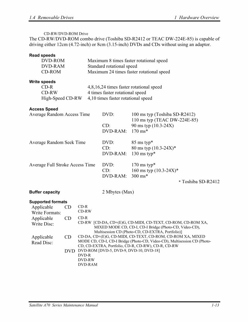
CD-RW/DVD-ROM Drive The CD-RW/DVD-ROM combo drive (Toshiba SD-R2412 or TEAC DW-224E-85) is capable of driving either 12cm (4.72-inch) or 8cm (3.15-inch) DVDs and CDs without using an adaptor. Read speeds
DVD-ROM Maximum 8 times faster rotational speed DVD-RAM Standard rotational speed CD-ROM Maximum 24 times faster rotational speed
Write speeds
CD-R 4,8,16,24 times faster rotational speed CD-RW 4 times faster rotational speed High-Speed CD-RW 4,10 times faster rotational speed
Access Speed Average Random Access Time DVD: 100 ms typ (Toshiba SD-R2412)
110 ms typ (TEAC DW-224E-85) CD: 90 ms typ (10.3-24X) DVD-RAM: 170 ms*
Average Random Seek Time DVD: 85 ms typ*
CD: 80 ms typ (10.3-24X)* DVD-RAM: 130 ms typ*
Average Full Stroke Access Time DVD: 170 ms typ*
CD: 160 ms typ (10.3-24X)* DVD-RAM: 300 ms*
* Toshiba SD-R2412 Buffer capacity 2 Mbytes (Max) Supported formats Applicable Write Formats:
CD CD-R CD-RW
Applicable Write Disc:
CD CD-R CD-RW [CD-DA, CD+(E)G, CD-MIDI, CD-TEXT, CD-ROM, CD-ROM XA,
MIXED MODE CD, CD-I, CD-I Bridge (Photo-CD, Video-CD), Multisession CD (Photo-CD, CD-EXTRA, Portfolio)]
Applicable Read Disc:
CD CD-DA, CD+(E)G, CD-MIDI, CD-TEXT, CD-ROM, CD-ROM XA, MIXED MODE CD, CD-I, CD-I Bridge (Photo-CD, Video-CD), Multisession CD (Photo-CD, CD-EXTRA, Portfolio, CD-R, CD-RW), CD-R, CD-RW
DVD DVD-ROM [DVD-5, DVD-9, DVD-10, DVD-18] DVD-R DVD-RW DVD-RAM
Satellite A70 Series Maintenance Manual 1-13
1 Hardware Overview 1.5 Power Supply
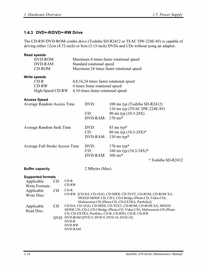
1.4.3 DVD+-R/DVD+-RW Drive
The CD-RW/DVD-ROM combo drive (Toshiba SD-R2412 or TEAC DW-224E-85) is capable of driving either 12cm (4.72-inch) or 8cm (3.15-inch) DVDs and CDs without using an adaptor. Read speeds
DVD-ROM Maximum 8 times faster rotational speed DVD-RAM Standard rotational speed CD-ROM Maximum 24 times faster rotational speed
Write speeds
CD-R 4,8,16,24 times faster rotational speed CD-RW 4 times faster rotational speed High-Speed CD-RW 4,10 times faster rotational speed
Access Speed Average Random Access Time DVD: 100 ms typ (Toshiba SD-R2412)
110 ms typ (TEAC DW-224E-85) CD: 90 ms typ (10.3-24X) DVD-RAM: 170 ms*
Average Random Seek Time DVD: 85 ms typ*
CD: 80 ms typ (10.3-24X)* DVD-RAM: 130 ms typ*
Average Full Stroke Access Time DVD: 170 ms typ*
CD: 160 ms typ (10.3-24X)* DVD-RAM: 300 ms*
* Toshiba SD-R2412 Buffer capacity 2 Mbytes (Max) Supported formats Applicable Write Formats:
CD CD-R CD-RW
Applicable Write Disc:
CD CD-R CD-RW [CD-DA, CD+(E)G, CD-MIDI, CD-TEXT, CD-ROM, CD-ROM XA,
MIXED MODE CD, CD-I, CD-I Bridge (Photo-CD, Video-CD), Multisession CD (Photo-CD, CD-EXTRA, Portfolio)]
Applicable Read Disc:
CD CD-DA, CD+(E)G, CD-MIDI, CD-TEXT, CD-ROM, CD-ROM XA, MIXED MODE CD, CD-I, CD-I Bridge (Photo-CD, Video-CD), Multisession CD (Photo-CD, CD-EXTRA, Portfolio, CD-R, CD-RW), CD-R, CD-RW
DVD DVD-ROM [DVD-5, DVD-9, DVD-10, DVD-18] DVD-R DVD-RW DVD-RAM
1-14 Satellite A70 Series Maintenance Manual
1.5 Power Supply 1 Hardware Overview
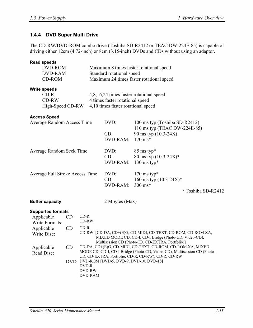
1.4.4 DVD Super Multi Drive
The CD-RW/DVD-ROM combo drive (Toshiba SD-R2412 or TEAC DW-224E-85) is capable of driving either 12cm (4.72-inch) or 8cm (3.15-inch) DVDs and CDs without using an adaptor. Read speeds
DVD-ROM Maximum 8 times faster rotational speed DVD-RAM Standard rotational speed CD-ROM Maximum 24 times faster rotational speed
Write speeds
CD-R 4,8,16,24 times faster rotational speed CD-RW 4 times faster rotational speed High-Speed CD-RW 4,10 times faster rotational speed
Access Speed Average Random Access Time DVD: 100 ms typ (Toshiba SD-R2412)
110 ms typ (TEAC DW-224E-85) CD: 90 ms typ (10.3-24X) DVD-RAM: 170 ms*
Average Random Seek Time DVD: 85 ms typ*
CD: 80 ms typ (10.3-24X)* DVD-RAM: 130 ms typ*
Average Full Stroke Access Time DVD: 170 ms typ*
CD: 160 ms typ (10.3-24X)* DVD-RAM: 300 ms*
* Toshiba SD-R2412 Buffer capacity 2 Mbytes (Max) Supported formats Applicable Write Formats:
CD CD-R CD-RW
Applicable Write Disc:
CD CD-R CD-RW [CD-DA, CD+(E)G, CD-MIDI, CD-TEXT, CD-ROM, CD-ROM XA,
MIXED MODE CD, CD-I, CD-I Bridge (Photo-CD, Video-CD), Multisession CD (Photo-CD, CD-EXTRA, Portfolio)]
Applicable Read Disc:
CD CD-DA, CD+(E)G, CD-MIDI, CD-TEXT, CD-ROM, CD-ROM XA, MIXED MODE CD, CD-I, CD-I Bridge (Photo-CD, Video-CD), Multisession CD (Photo-CD, CD-EXTRA, Portfolio, CD-R, CD-RW), CD-R, CD-RW
DVD DVD-ROM [DVD-5, DVD-9, DVD-10, DVD-18] DVD-R DVD-RW DVD-RAM
Satellite A70 Series Maintenance Manual 1-15
1 Hardware Overview 1.5 Power Supply
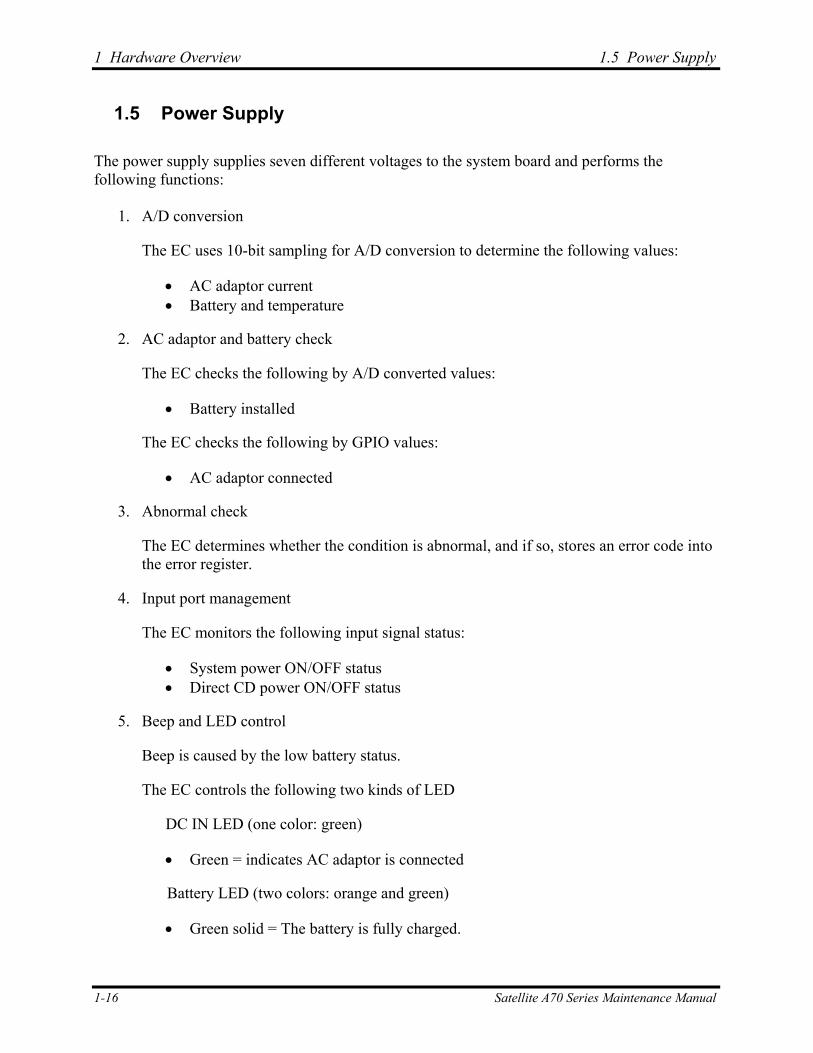
1.5 Power Supply
The power supply supplies seven different voltages to the system board and performs the following functions:
1. A/D conversion
The EC uses 10-bit sampling for A/D conversion to determine the following values:
• AC adaptor current • Battery and temperature
2. AC adaptor and battery check
The EC checks the following by A/D converted values:
• Battery installed
The EC checks the following by GPIO values:
• AC adaptor connected
3. Abnormal check
The EC determines whether the condition is abnormal, and if so, stores an error code into the error register.
4. Input port management
The EC monitors the following input signal status:
• System power ON/OFF status • Direct CD power ON/OFF status
5. Beep and LED control
Beep is caused by the low battery status.
The EC controls the following two kinds of LED
DC IN LED (one color: green)
• Green = indicates AC adaptor is connected
Battery LED (two colors: orange and green)
• Green solid = The battery is fully charged.
1-16 Satellite A70 Series Maintenance Manual

1.5 Power Supply 1 Hardware Overview
• Orange = The computer is quick-charging the battery / The battery is low.
6. Power ON/OFF sequence
When power is turned on or off, the EC starts the power on or off sequence.
• SQ0-4 = power ON sequence • SQ5-B = power OFF sequence
7. Battery charging control
The EC controls the following.
• The quick charging ON/OFF • The detection of full charge
8. Detection of the low battery
The EC detects the low battery point by the gas gauge.
• LB10M = The system will be driven by the battery for 12 more minutes. • LB0 = The battery won't be able to drive the system after 3 minutes. • LB1 = The battery can drive the system only during the suspend process. • LB2 = The battery cannot drive the system.
9. New battery installation
When a new battery is installed, the EC communicates with the E2PROM in the battery to read information of the newly installed battery.
10. Battery capacity calculation
The EC reads battery remaining and percentage capacity from the battery through SMBus.
Satellite A70 Series Maintenance Manual 1-17
1 Hardware Overview 1.6 Batteries
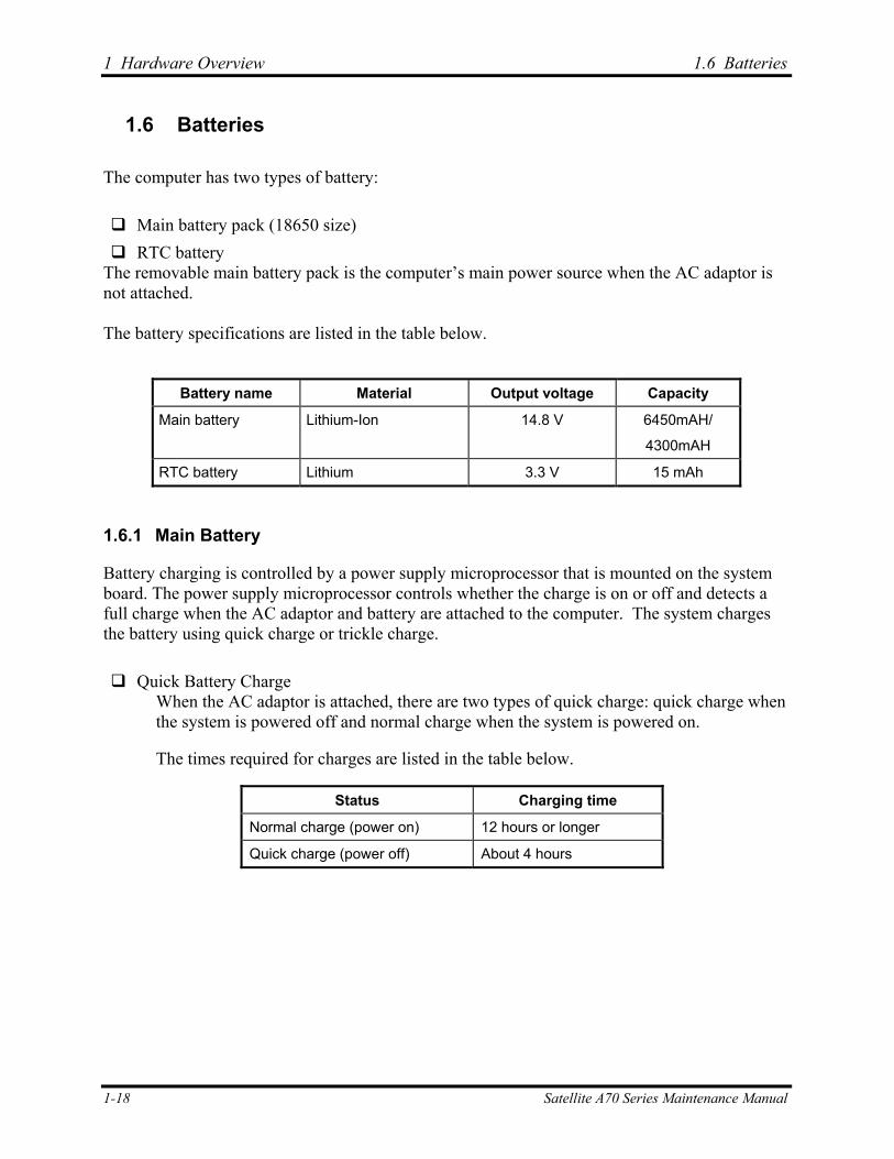
1.6 Batteries
The computer has two types of battery: Main battery pack (18650 size) RTC battery
The removable main battery pack is the computer’s main power source when the AC adaptor is not attached. The battery specifications are listed in the table below.
Battery name Material Output voltage Capacity
Main battery Lithium-Ion 14.8 V 6450mAH/
4300mAH
RTC battery Lithium 3.3 V 15 mAh
1.6.1 Main Battery
Battery charging is controlled by a power supply microprocessor that is mounted on the system board. The power supply microprocessor controls whether the charge is on or off and detects a full charge when the AC adaptor and battery are attached to the computer. The system charges the battery using quick charge or trickle charge. Quick Battery Charge
When the AC adaptor is attached, there are two types of quick charge: quick charge when the system is powered off and normal charge when the system is powered on.
The times required for charges are listed in the table below.
Status Charging time
Normal charge (power on) 12 hours or longer
Quick charge (power off) About 4 hours
1-18 Satellite A70 Series Maintenance Manual
1.6 Batteries 1 Hardware Overview
NOTES
1. The time required for normal charge is affected by the amount of power the system is consuming. Use of the fluorescent lamp and frequent disk access diverts power and lengthens the charge time.
2. Using quick charge, the power supply microprocessor automatically stops the charge after eight hours regardless of the condition of the battery. Overcharging could cause the battery to explode.
If any of the following occurs, the battery quick charge process stops.
1. The battery becomes fully charged.
2. The AC adaptor or battery is removed.
3. The battery or output voltage is abnormal.
4. The battery temperature is abnormal.
5. The battery SMBus communication fails.
6. The battery cell is bad.
Detection of full charge A full charge is detected from the battery pack through SMBus when the battery is charging.
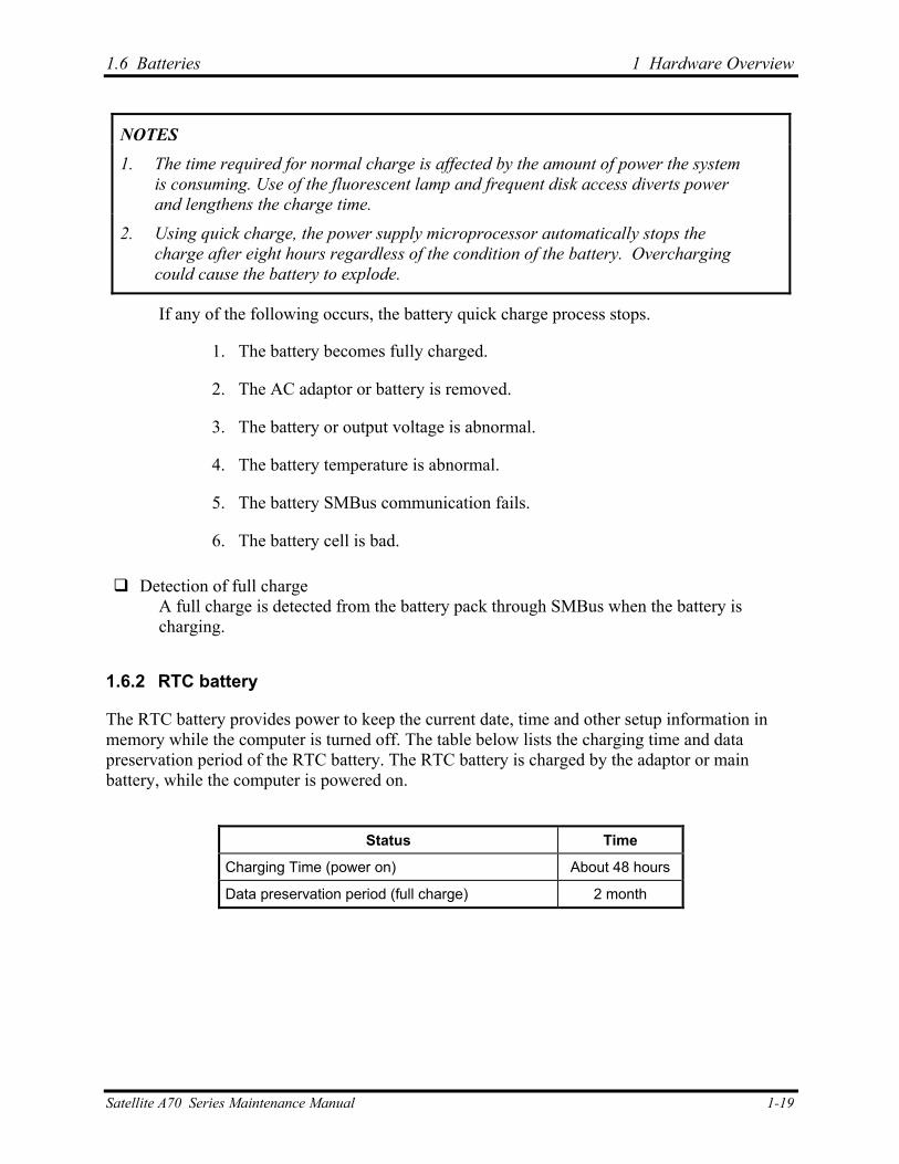
1.6.2 RTC battery
The RTC battery provides power to keep the current date, time and other setup information in memory while the computer is turned off. The table below lists the charging time and data preservation period of the RTC battery. The RTC battery is charged by the adaptor or main battery, while the computer is powered on.
Status Time
Charging Time (power on) About 48 hours
Data preservation period (full charge) 2 month
Satellite A70 Series Maintenance Manual 1-19
1 Hardware Overview 1.6 Batteries
1-20 Satellite A70 Series Maintenance Manual
Chapter 2 Troubleshooting Procedures 2
2 Troubleshooting Procedures
2-ii Satellite A70 Series Maintenance Manual
2 Troubleshooting Procedures
Chapter 2 Contents
2.1 Troubleshooting Introduction .................................................................................... 2-1
2.2 Troubleshooting Flowchart........................................................................................ 2-2
2.3 Power Supply Troubleshooting.................................................................................. 2-7
2.4 Display Troubleshooting............................................................................. ……….2-12
2.5 Keyboard Troubleshooting ...................................................................................... 2-15
2.6 External USB Devices Troubleshooting.................................................................. 2-17
2.7 TV-Out Failure Troubleshooting ............................................................................. 2-19
2.8 Printer Port Troubleshooting.................................................................................... 2-21
2.9 TouchPad Troubleshooting...................................................................................... 2-23
2.10 Speaker Troubleshooting ......................................................................................... 2-25
2.11 Optical Drive Troubleshooting ................................................................................ 2-27
2.12 Modem Troubleshooting.......................................................................................... 2-30
2.13 PCMCIA Troubleshooting....................................................................................... 2-32
2.14 IEEE 1394 Troubleshooting .................................................................................... 2-34
2.16 Wireless LAN Troubleshooting............................................................................... 2-36
Satellite A70 Series Maintenance Manual 2-iii
2 Troubleshooting Procedures
Figures
Figure 2-1 Troubleshooting flowchart (1/2) ....................................................................2-3
Figure 2-1 Troubleshooting flowchart (2/2) ....................................................................2-4
Figure 2-2 Power Supply Troubleshooting Process.........................................................2-7
Figure 2-3 Display troubleshooting process ..................................................................2-12
Figure 2-4 Keyboard troubleshooting process ...............................................................2-15
Figure 2-5 External USB device troubleshooting process .............................................2-17
Figure 2-6 TV-out troubleshooting process ...................................................................2-19
Figure 2-7 Printer port troubleshooting process.............................................................2-21
Figure 2-8 TouchPad troubleshooting process...............................................................2-23
Figure 2-9 Speaker troubleshooting process ..................................................................2-25
Figure 2-10 Optical drive troubleshooting process..........................................................2-27
Figure 2-11 Modem troubleshooting process ..................................................................2-30
Figure 2-12 PCMCIA troubleshooting process................................................................2-32
Figure 2-13 IEEE 1394 troubleshooting process .............................................................2-34
Figure 2-14 Wireless LAN troubleshooting process........................................................2-36
Tables
Table 2-1 Battery LED ......................................................................................................2-8
Table 2-2 DC-IN LED .......................................................................................................2-9
2-iv Satellite A70 Series Maintenance Manual
2.1 Troubleshooting Introduction 2 Troubleshooting Procedures
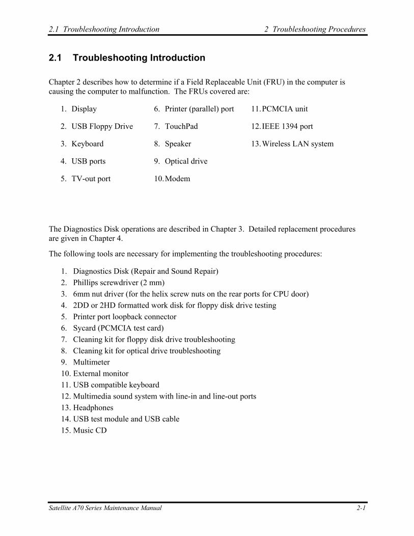
2.1 Troubleshooting Introduction
Chapter 2 describes how to determine if a Field Replaceable Unit (FRU) in the computer is causing the computer to malfunction. The FRUs covered are:
1. Display 6. Printer (parallel) port 11. PCMCIA unit
2. USB Floppy Drive 7. TouchPad 12. IEEE 1394 port
3. Keyboard 8. Speaker 13. Wireless LAN system
4. USB ports 9. Optical drive
5. TV-out port 10. Modem
The Diagnostics Disk operations are described in Chapter 3. Detailed replacement procedures are given in Chapter 4.
The following tools are necessary for implementing the troubleshooting procedures:
1. Diagnostics Disk (Repair and Sound Repair) 2. Phillips screwdriver (2 mm) 3. 6mm nut driver (for the helix screw nuts on the rear ports for CPU door) 4. 2DD or 2HD formatted work disk for floppy disk drive testing 5. Printer port loopback connector 6. Sycard (PCMCIA test card) 7. Cleaning kit for floppy disk drive troubleshooting 8. Cleaning kit for optical drive troubleshooting 9. Multimeter 10. External monitor 11. USB compatible keyboard 12. Multimedia sound system with line-in and line-out ports 13. Headphones 14. USB test module and USB cable 15. Music CD
Satellite A70 Series Maintenance Manual 2-1

2 Troubleshooting Procedures 2.3 Power Supply Troubleshooting
2.2 Troubleshooting Flowchart
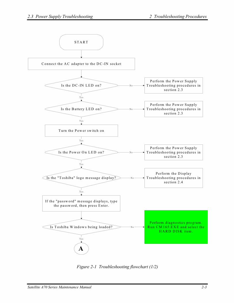
If you know the location of the malfunction, turn directly to the appropriate section of this chapter. If the problem is unspecified, use the flowchart in Figure 2-1 as a guide for determining which troubleshooting procedures to execute. Before performing any troubleshooting procedures, verify the following:
Ask the user if a password is registered and, if it is, ask him or her to enter the password.
Verify with the customer that Toshiba Windows XP is installed on the hard disk. Operating systems that were not preinstalled by Toshiba can cause the computer to malfunction.
Make sure all optional equipment is removed from the computer.
Make sure the floppy disk drive, if installed, is empty. If no FDD module is installed, you should use an external FDD to run the diagnostics tests
2-2 Satellite A70 Series Maintenance Manual
2.3 Power Supply Troubleshooting 2 Troubleshooting Procedures
S T A R T
C onnect the A C adap ter to the D C -IN socket
Is the D C -IN L E D on?
Is the B attery L E D on?
T urn the P ow er sw itch on
Is the P ow er O n L E D on?
Is the "T osh iba" logo m essage d isp lay?
If the "passw ord" m essage d isp lays, typethe passw ord , then press E nter.
Is T osh iba W indow s being loaded?
A
Yes
Y es
Y es
Y es
Y es
Y es
P erform the P ow er S upp lyT roub leshoo ting p rocedures in
section 2 .3
P erfo rm d iagnostics p rogram .R un C M 165 .E X E and se lec t the
H A R D D IS K item .
P erfo rm the D isp layT roub leshoo ting p rocedures in
section 2 .4
P erform the P ow er S upp lyT roub leshoo ting p rocedures in
section 2 .3
P erform the P ow er S upp lyT roub leshoo ting p rocedures in
section 2 .3
No
No
No
No
No
Figure 2-1 Troubleshooting flowchart (1/2)
Satellite A70 Series Maintenance Manual 2-3
2 Troubleshooting Procedures 2.3 Power Supply Troubleshooting
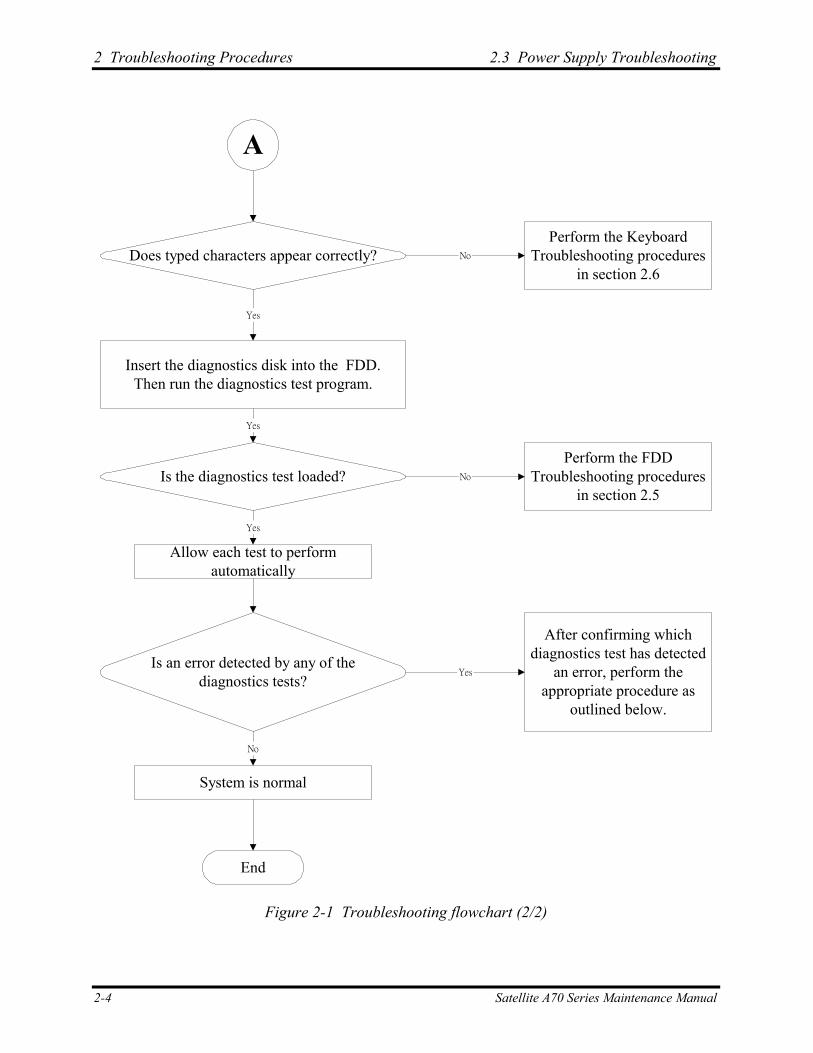
A
Does typed characters appear correctly?
Insert the diagnostics disk into the FDD.Then run the diagnostics test program.
Is the diagnostics test loaded?
Allow each test to performautomatically
Is an error detected by any of thediagnostics tests?
System is normal
End
Yes
Yes
Yes
No
Perform the KeyboardTroubleshooting procedures
in section 2.6
Perform the FDDTroubleshooting procedures
in section 2.5
After confirming whichdiagnostics test has detected
an error, perform theappropriate procedure as
outlined below.
No
No
Yes
Figure 2-1 Troubleshooting flowchart (2/2)
2-4 Satellite A70 Series Maintenance Manual
2.3 Power Supply Troubleshooting 2 Troubleshooting Procedures
If the diagnostics program cannot detect an error, the problem may be intermittent. The test program should be executed several times to isolate the problem. When a problem has been located, perform the appropriate troubleshooting procedures as follows:
1. If an error is detected by the battery test, perform the Power Supply Troubleshooting procedures in Section 2.3.
2. If an error is detected by the display test, perform the Display Troubleshooting procedures in Section 2.4.
3. If an error is detected by the keyboard test, perform the Keyboard Troubleshooting procedures in Section 2.5.
4. If an error is detected by the printer (parallel) port test, perform the Printer Port Troubleshooting procedures in Section 2.8.
5. If an error is detected by the TouchPad test, perform the TouchPad Troubleshooting procedures in Section 2.9.
6. If an error is detected by the audio test, perform the Speaker Troubleshooting procedures in Section 2.10 and the Optical Drive Troubleshooting Procedures in Section 2.12.
7. If an error is detected by the modem test, perform the Modem Troubleshooting Procedures in Section 2.12.
Satellite A70 Series Maintenance Manual 2-5
2 Troubleshooting Procedures 2.3 Power Supply Troubleshooting
Other problems that are not covered by the diagnostics program may be discovered by a user.
1. If an error is detected when using an external USB device, perform the External USB Devices Troubleshooting procedures in Section 2.6.
2. If an error is detected when using the TV-out connection, perform the TV-Out Failure Troubleshooting procedures in Section 2.7.
3. If an error is detected when using the speakers, perform the Speaker Troubleshooting procedures in Section 2.10.
4. If an error is detected when using the modem, perform the Modem Troubleshooting procedures in Section 2.12.
5. If an error is detected when using the PCMCIA unit, perform the PCMCIA Troubleshooting procedures in Section 2.13.
6. If an error is detected when using the IEEE1394 device, perform the IEEE1394 device Troubleshooting procedures in Section 2.14.
7. If an error is detected when using the Wireless LAN, perform the Wireless LAN Troubleshooting procedures in Section 2.15.
2-6 Satellite A70 Series Maintenance Manual
2.3 Power Supply Troubleshooting 2 Troubleshooting Procedures
2.3 Power Supply Troubleshooting
ST ART
Are the DC-IN andBattery LEDs lit?
Can you turn thecomputer on?
Are the internal powerconnections secure?
END
Check Power Supply Status(Procedure 1)
No
Yes
Check power supplyconnections
(Procedure 3)
Run diagnostic program(Procedure 4)
Yes
No
Replace adaptor / battery(Procedure 2)
No
Perform internal connectioncheck
(Procedure 5)
Replace system board
Yes
Figure 2-2 Power Supply Troubleshooting Process
Satellite A70 Series Maintenance Manual 2-7
2 Troubleshooting Procedures 2.3 Power Supply Troubleshooting
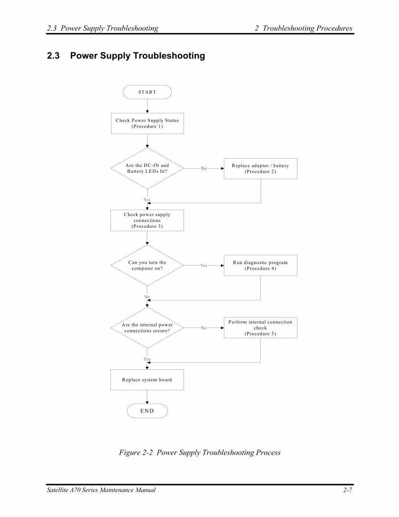
The power supply controls many functions and components. To determine if the power supply is functioning properly, start with Procedure 1 and continue with the other Procedures as instructed. The flowchart in Figure 2-2 gives a summary of the process. The procedures described in this section are:
Procedure 1: Power status check
Procedure 2: Adaptor / battery replacement
Procedure 3: Power supply connection check
Procedure 4: Diagnostic check
Procedure 5: Internal connection check
Procedure 1 Power Status Check
The following LEDs indicate the power supply status:
Battery LED
DC-IN LED
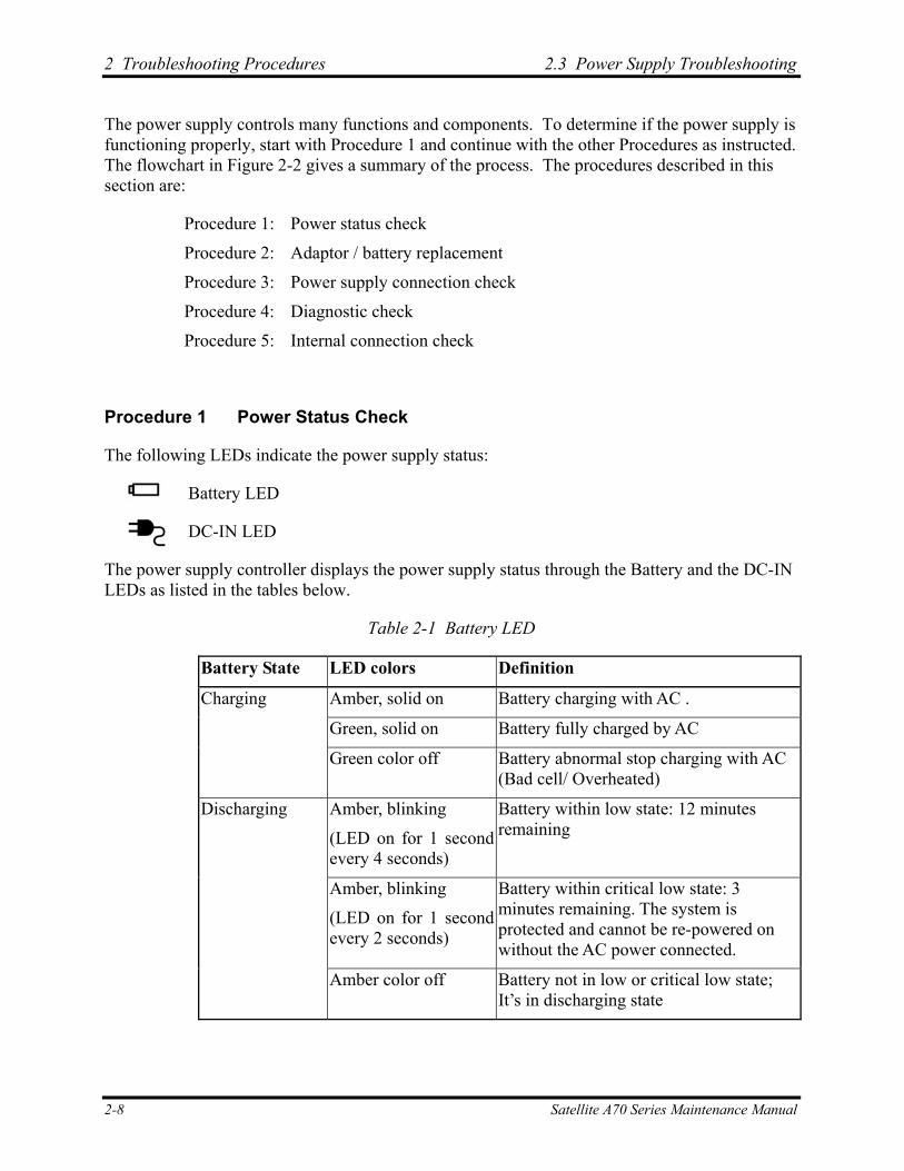
The power supply controller displays the power supply status through the Battery and the DC-IN LEDs as listed in the tables below.
Table 2-1 Battery LED
Battery State LED colors Definition
Amber, solid on Battery charging with AC .
Green, solid on Battery fully charged by AC
Charging
Green color off Battery abnormal stop charging with AC (Bad cell/ Overheated)
Amber, blinking
(LED on for 1 second every 4 seconds)
Battery within low state: 12 minutes remaining
Amber, blinking
(LED on for 1 second every 2 seconds)
Battery within critical low state: 3 minutes remaining. The system is protected and cannot be re-powered on without the AC power connected.
Discharging
Amber color off Battery not in low or critical low state; It’s in discharging state
2-8 Satellite A70 Series Maintenance Manual
2.3 Power Supply Troubleshooting 2 Troubleshooting Procedures
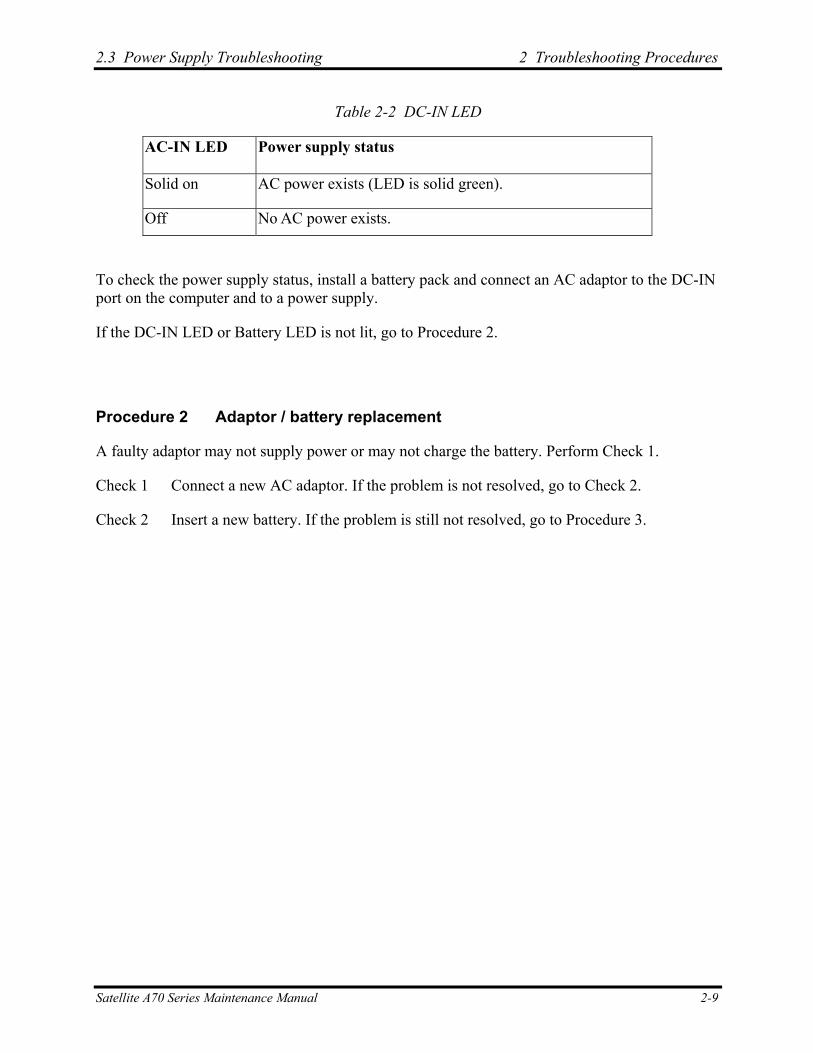
Table 2-2 DC-IN LED
AC-IN LED Power supply status
Solid on AC power exists (LED is solid green).
Off No AC power exists.
To check the power supply status, install a battery pack and connect an AC adaptor to the DC-IN port on the computer and to a power supply.
If the DC-IN LED or Battery LED is not lit, go to Procedure 2.
Procedure 2 Adaptor / battery replacement
A faulty adaptor may not supply power or may not charge the battery. Perform Check 1.
Check 1 Connect a new AC adaptor. If the problem is not resolved, go to Check 2.
Check 2 Insert a new battery. If the problem is still not resolved, go to Procedure 3.
Satellite A70 Series Maintenance Manual 2-9
2 Troubleshooting Procedures 2.3 Power Supply Troubleshooting
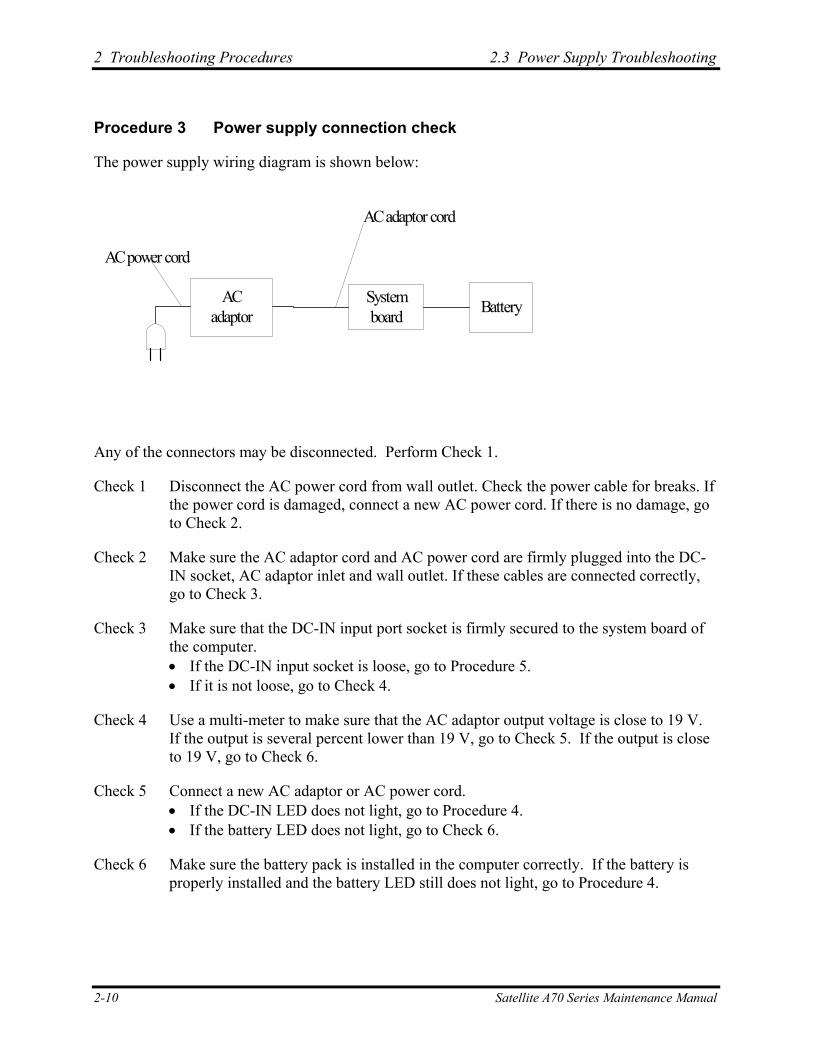
Procedure 3 Power supply connection check
The power supply wiring diagram is shown below:
ACadaptor
Systemboard Battery
AC adaptor cord
AC power cord
Any of the connectors may be disconnected. Perform Check 1.
Check 1 Disconnect the AC power cord from wall outlet. Check the power cable for breaks. If the power cord is damaged, connect a new AC power cord. If there is no damage, go to Check 2.
Check 2 Make sure the AC adaptor cord and AC power cord are firmly plugged into the DC-IN socket, AC adaptor inlet and wall outlet. If these cables are connected correctly, go to Check 3.
Check 3 Make sure that the DC-IN input port socket is firmly secured to the system board of the computer. • If the DC-IN input socket is loose, go to Procedure 5. • If it is not loose, go to Check 4.
Check 4 Use a multi-meter to make sure that the AC adaptor output voltage is close to 19 V. If the output is several percent lower than 19 V, go to Check 5. If the output is close to 19 V, go to Check 6.
Check 5 Connect a new AC adaptor or AC power cord. • If the DC-IN LED does not light, go to Procedure 4. • If the battery LED does not light, go to Check 6.
Check 6 Make sure the battery pack is installed in the computer correctly. If the battery is properly installed and the battery LED still does not light, go to Procedure 4.
2-10 Satellite A70 Series Maintenance Manual
2.3 Power Supply Troubleshooting 2 Troubleshooting Procedures
Procedure 4 Diagnostic check
The power supply may not charge the battery pack. Perform the following procedures:
1. Reinstall the battery pack.
2. Attach the AC adaptor and turn on the power. If you cannot turn on the power, go to Procedure 5.
3. Run the Diagnostic test following the procedures described in Chapter 3, Tests and Diagnostics. If no problem is detected, the battery is functioning normally.
Procedure 5 Replacement check
The system board may be disconnected or damaged. Disassemble the computer following the steps described in Chapter 4, Replacement Procedures. Check the connection between the AC adaptor and the system board. After checking the connection, perform Check 1:
Check 1 Use a multi-meter to make sure that the fuses on the system board are not blown. If a fuse is not blown, go to Check 2. If a fuse is blown, go to Check 3.
Check 2 Make sure that the battery cable is firmly connected to the system board. If it is connected firmly, go to Check 3.
Check 3 The system board may be damaged. Replace it with a new one following the instructions in Chapter 4.
Satellite A70 Series Maintenance Manual 2-11
2 Troubleshooting Procedures 2.4 Display Troubleshooting
2.4 Display Troubleshooting
P e rfo rm e x te rn a l d isp la y c h e c k(P ro c e d u re 1 )
S T A R T
D o e s th e e x te rn a ld isp la y fu n c tio n o k ?
P e rfo rm d ia g n o s tic c h e c k(P ro c e d u re 2 )
N o
W a s a d isp la yp ro b le m d e te c te d ?
P e rfo rm c o n n e c to r a n dre p la c e m e n t c h e c k
(P ro c e d u re 3 )
R e p la c e sys te m b o a rd
E N D
Y es
Y es
N o
D isp la y is n o tfa u lty . C o n tin u etro u b le sh o o tin g -
re fe r to F ig u re 2 .1
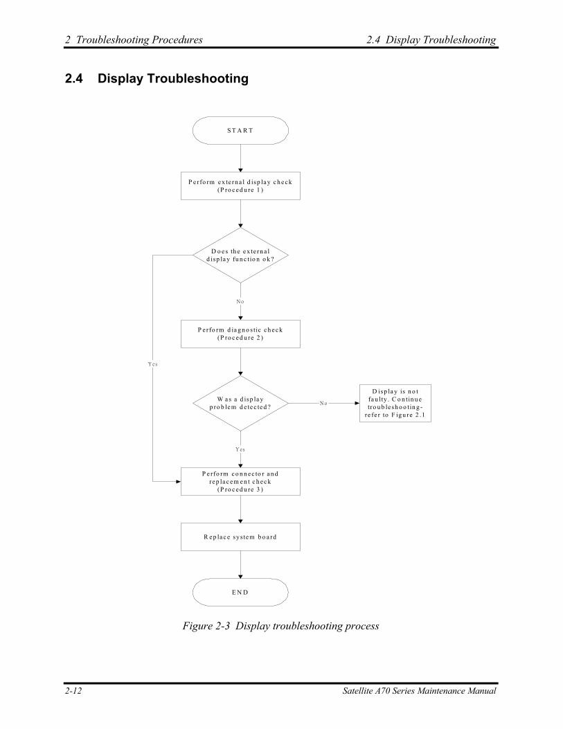
Figure 2-3 Display troubleshooting process
2-12 Satellite A70 Series Maintenance Manual
2.4 Display Troubleshooting 2 Troubleshooting Procedures
This section describes how to determine if the computer’s display is functioning properly. The process is outlined in Figure 2-3. Start with Procedure 1 and continue with the other procedures as instructed.
Procedure 1: External display check
Procedure 2: Diagnostic check
Procedure 3: Connector and replacement check
Procedure 1 External display check
Connect an external display to the computer’s external monitor port, then boot the computer. The computer automatically detects the external display.
If the external display works correctly, the internal LCD may be damaged. Go to Procedure 3.
If the external monitor appears to have the same problem as the internal monitor, the system board may be damaged. Go to Procedure 2.
Procedure 2 Diagnostic check
The Display Test program is stored on the computer’s Diagnostics disk. This program checks the display controller on the system board. Insert the Diagnostics disk in the computer’s floppy disk drive, turn on the computer and run the test. Refer to Chapter 3, Tests and Diagnostics for details.
If an error is detected, go to Procedure 3. If an error is not detected, the display is functioning properly.
Satellite A70 Series Maintenance Manual 2-13
2 Troubleshooting Procedures 2.4 Display Troubleshooting
Procedure 3 Connector and replacement check
The FL inverter board, LCD module, and system board are connected to the display circuits. Any of these components may be damaged. Refer to Chapter 4, Replacement Procedures, for instructions on how to disassemble the computer and then perform the following checks:
Check 1 Make sure the DDR RAM module is seated properly. Test display again. If the problem still exits, replace the DDR RAM module. If the problem still exists, perform Check 2.
Check 2 Replace the FL inverter board with a new one and test display again. If the problem still exists, perform Check 3.
Check 3 Replace the LCD module with a new one and test display again. If the problem still exists, perform Check 4.
Check 4 Replace the LCD/FL cable with a new one and test display again. If the problem still exists, perform Check 5.
Check 5 Replace the CPU with another of the same specifications. If the problem still exists, perform Check 6.
Check 6 The system board may be damaged. Replace it with a new one.
2-14 Satellite A70 Series Maintenance Manual
2.5 Keyboard Troubleshooting 2 Troubleshooting Procedures
2.5 Keyboard Troubleshooting
P e rfo rm e x te rn a l k e yb o a rd c h e c k(P ro c e d u re 1 )
S T A R T
D o e s th e e x te rn a lk e yb o a rd fu n c tio n o k ?
P e rfo rm d ia g n o s tic c h e c k(P ro c e d u re 2 )
W a s a k e yb o a rdp ro b le m d e te c te d ?
P e rfo rm c o n n e c to r a n dre p la c e m e n t c h e c k
(P ro c e d u re 3 )
R e p la c e sys te m b o a rd
E N D
Y es
N o
K e yb o a rd is n o tfa u lty . C o n tin u etro u b le sh o o tin g -
re fe r to F ig u re 2 .1
N o
Y es
Figure 2-4 Keyboard troubleshooting process
Satellite A70 Series Maintenance Manual 2-15
2 Troubleshooting Procedures 2.5 Keyboard Troubleshooting
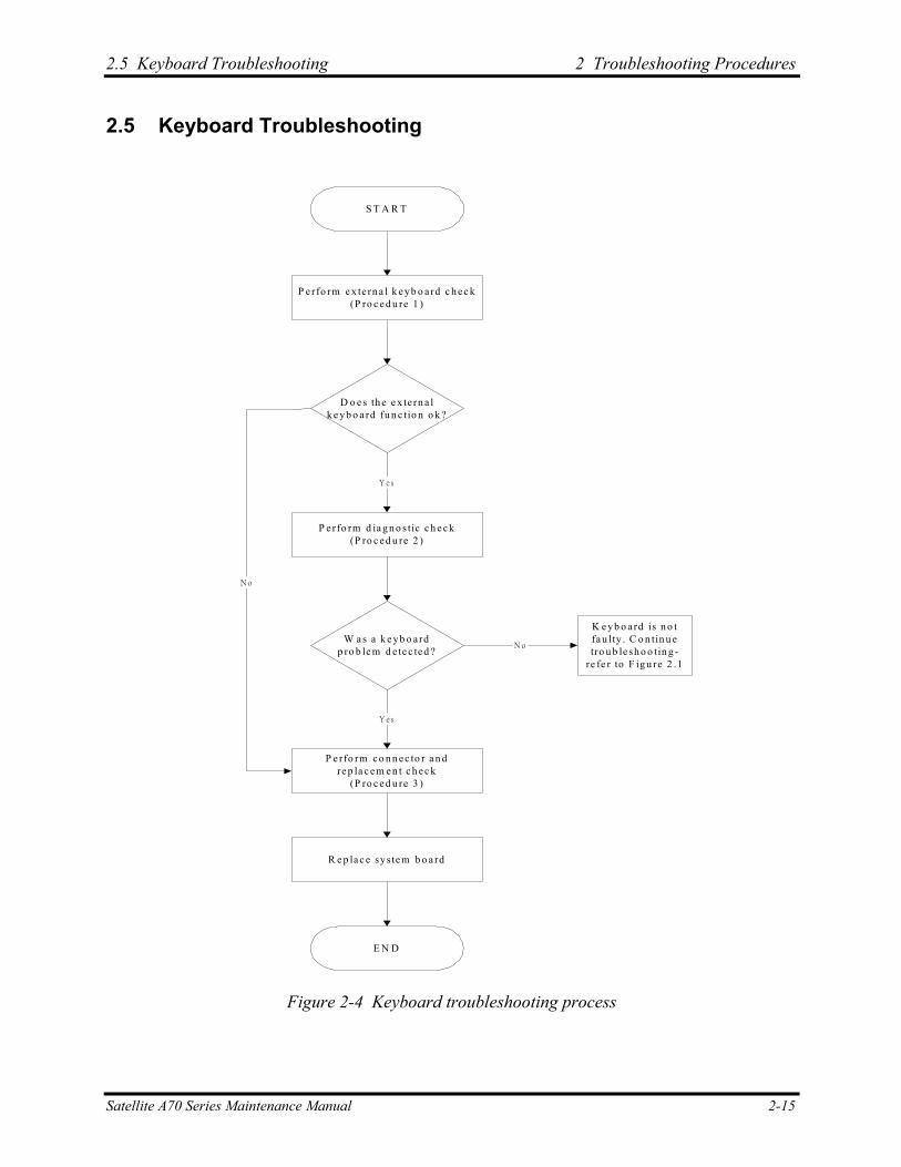
To determine if the computer’s keyboard is functioning properly, perform the following procedures. Figure 2-5 outlines the process. Start with Procedure 1 and continue with the other procedures as instructed.
Procedure 1: External keyboard check
Procedure 2: Diagnostic check
Procedure 3: Connector and replacement check
Procedure 1 External keyboard check
Connect a USB keyboard to one of the computer’s USB ports, then boot the computer. The computer automatically detects the external keyboard.
If the external keyboard works correctly, the internal keyboard or its connections may be faulty. Go to Procedure 2.
If the external keyboard appears to have the same problem as the internal keyboard, the system board may be damaged. Replace it with a new one following the instructions in Chapter 4.
Procedure 2 Diagnostic check
Run the Diagnostic Program, which will automatically execute the Keyboard Test. Refer to Chapter 3, Tests and Diagnostics for more information on how to run the program.
If an error is located, go to Procedure 3. If an error does not occur, the keyboard is functioning properly.
Procedure 3 Connector and replacement check
The keyboard and/or system board may be disconnected or damaged. Disassemble the computer following the steps described in Chapter 4, Replacement Procedures and perform the following checks.
Check 1 Make sure the keyboard cable is firmly connected to the system board.
If the connection is loose, reconnect firmly and repeat Procedure 2. If there is still an error, go to Check 2.
Check 2 The keyboard may be damaged. Replace it with a new one following the instructions in Chapter 4.
If the problem still exists, perform Check 3.
Check 3 The system board may be damaged. Replace it with a new one following the instructions in Chapter 4.
2-16 Satellite A70 Series Maintenance Manual
2.6 External USB Devices Troubleshooting 2 Troubleshooting Procedures
2.6 External USB Devices Troubleshooting
R e p la c e sys te m b o a rd(P ro c e d u re 2 )
E N D
O rig in a l U S Bd e v ic e is fa u lty
P e rfo rm e x te rn a l d e v ic e a n dc o n n e c tio n c h e c k
(P ro c e d u re 1 )
S T A R T
D o e s th e d e v ic e fu n c tio nw h e n c o n n e c te d to ad iffe re n t U S B p o rt?
D o e s a n a lte rn a tiv e U S Bd e v ic e fu n c tio n c o rre c tly?
N o
Y es
N o
C h e c k U S B p o rtc o n n e c tio n
Y es
Figure 2-5 External USB device troubleshooting process
Satellite A70 Series Maintenance Manual 2-17
2 Troubleshooting Procedures 2.6 External USB Devices Troubleshooting
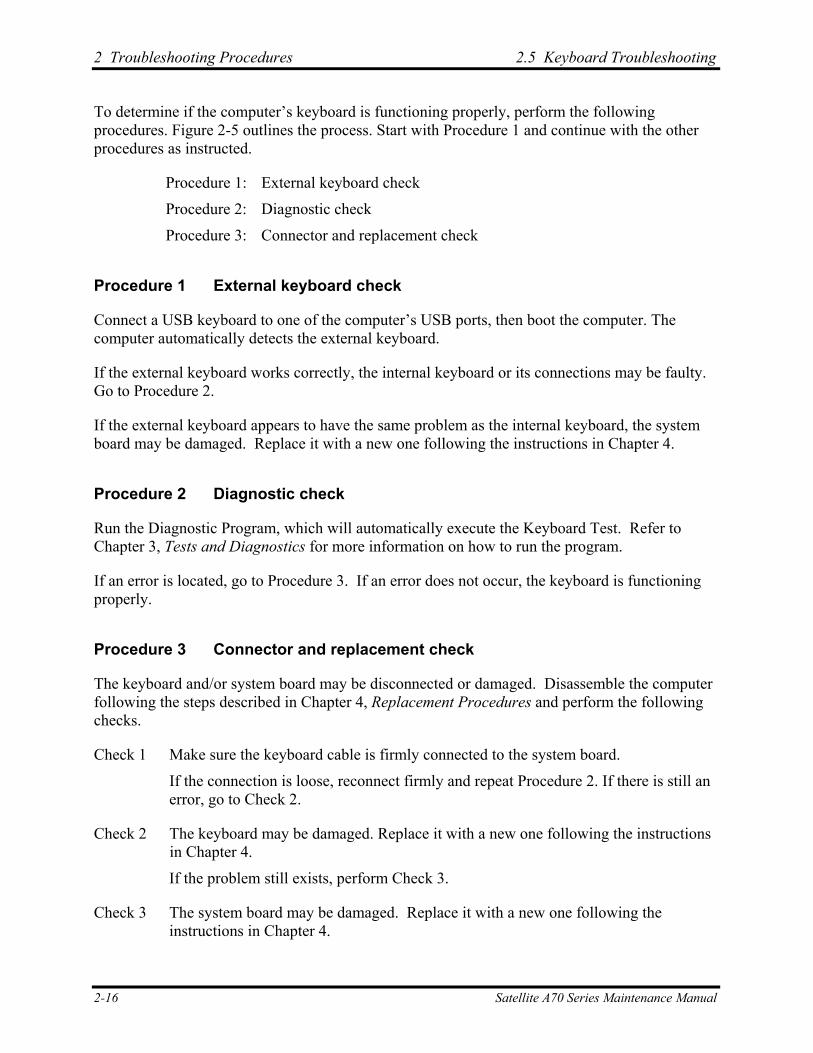
To determine if the computer’s external USB devices are functioning properly, perform the following procedures. Figure 2-6 outlines the process. Start with Procedure 1 and continue as instructed.
Procedure 1: External device and connection check
Procedure 2: Replace system board
Procedure 1 External device and connection check
The USB device may be damaged or the connection may be faulty. Perform Check 1.
Check 1 Make sure USB device cable is firmly plugged into one of the USB sockets. If the cable is connected correctly, go to Check 2.
Check 2 Plug the USB device into another USB socket (there are three in all). If the USB device still does not work, go to Check 4.
If the device functions correctly when connected to another USB port, go to Check 3.
Check 3 Make sure that the USB socket is firmly secured to the system board of the computer. If the malfunction remains, the system board may be damaged. Go to Procedure 2.
Check 4 Connect an alternative USB device to one of the computer’s USB ports, and then boot the computer. The computer automatically detects the external device.
If the alternative USB device works correctly, the original device may be damaged and should be replaced.
If the alternative USB device appears to have the same problem as the original device, the system board may be damaged. Go to Procedure 2.
Procedure 2 Replace system board
If the error persists, the system board may be damaged. Replace it with a new one following the instructions in Chapter 4.
2-18 Satellite A70 Series Maintenance Manual
2.7 TV-Out Failure Troubleshooting 2 Troubleshooting Procedures
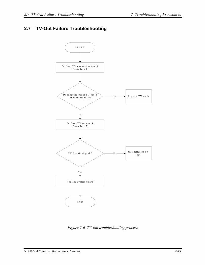
2.7 TV-Out Failure Troubleshooting
P e rfo rm T V c o n n e c tio n c h e c k(P ro c e d u re 1 )
S T A R T
D o e s re p la c e m e n t T V c a b lefu n c tio n p ro p e r ly?
P e rfo rm T V se t c h e c k(P ro c e d u re 2 )
R e p la c e sys te m b o a rd
E N D
N o R e p la c e T V c a b le
N o
T V fu n c tio n in g o k ?
Y es
U se d iffe re n t T Vse t
N o
Figure 2-6 TV-out troubleshooting process
Satellite A70 Series Maintenance Manual 2-19

2 Troubleshooting Procedures 2.7 TV-Out Failure Troubleshooting
To determine if the computer’s TV-out port is functioning properly, perform the following procedures. Figure 2-7 outlines the process. Start with Procedure 1 and continue as instructed.
Procedure 1: TV connection check
Procedure 2: TV set check
Procedure 1 TV connection check
The TV cable may be damaged or the connections may be loose. Perform Check 1:
Check 1 Make sure TV cable is firmly plugged into both the TV set and the TV-out port of the computer. If the cable is connected correctly, go to Check 2.
Check 2 Make sure the TV-out port is firmly secured to the system board of the computer. If the malfunction remains, go to Check 3.
Check 3 The TV cable may be damaged. Replace with a good cable. If the malfunction remains, go to Procedure 2.
Procedure 2 TV set check
The TV set may be faulty. Perform Check 1:
Check 1 Try using the set for television reception. If it does not work, the set may be damaged. If the set does work, perform Check 2.
Check 2 Try connecting a different television to the computer. If the replacement television works, the original set may be damaged. If the replacement set does not work the system board may be damaged. Replace it with a new one following the instructions in Chapter 4.
2-20 Satellite A70 Series Maintenance Manual
2.8 Printer Port Troubleshooting 2 Troubleshooting Procedures
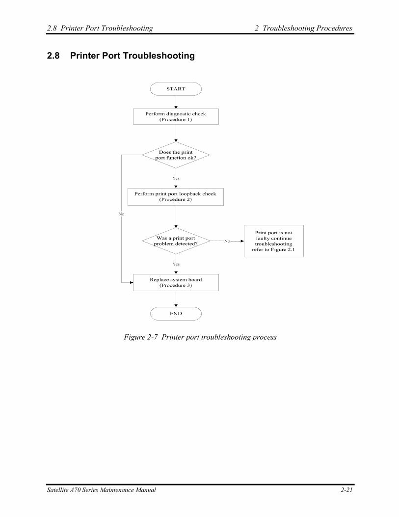
2.8 Printer Port Troubleshooting
START
Perform diagnostic check(Procedure 1)
Does the printport function ok?
Perform print port loopback check(Procedure 2)
Print port is notfaulty continuetroubleshooting
refer to Figure 2.1
Was a print portproblem detected?
Replace system board(Procedure 3)
END
Yes
Yes
No
No
Figure 2-7 Printer port troubleshooting process
Satellite A70 Series Maintenance Manual 2-21
2 Troubleshooting Procedures 2.8 Printer Port Troubleshooting
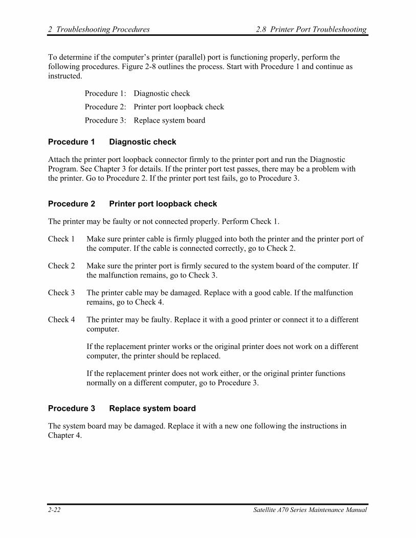
To determine if the computer’s printer (parallel) port is functioning properly, perform the following procedures. Figure 2-8 outlines the process. Start with Procedure 1 and continue as instructed.
Procedure 1: Diagnostic check
Procedure 2: Printer port loopback check
Procedure 3: Replace system board
Procedure 1 Diagnostic check
Attach the printer port loopback connector firmly to the printer port and run the Diagnostic Program. See Chapter 3 for details. If the printer port test passes, there may be a problem with the printer. Go to Procedure 2. If the printer port test fails, go to Procedure 3.
Procedure 2 Printer port loopback check
The printer may be faulty or not connected properly. Perform Check 1.
Check 1 Make sure printer cable is firmly plugged into both the printer and the printer port of the computer. If the cable is connected correctly, go to Check 2.
Check 2 Make sure the printer port is firmly secured to the system board of the computer. If the malfunction remains, go to Check 3.
Check 3 The printer cable may be damaged. Replace with a good cable. If the malfunction remains, go to Check 4.
Check 4 The printer may be faulty. Replace it with a good printer or connect it to a different computer.
If the replacement printer works or the original printer does not work on a different computer, the printer should be replaced.
If the replacement printer does not work either, or the original printer functions normally on a different computer, go to Procedure 3.
Procedure 3 Replace system board
The system board may be damaged. Replace it with a new one following the instructions in Chapter 4.
2-22 Satellite A70 Series Maintenance Manual
2.9 Touch Pad Troubleshooting 2 Troubleshooting Procedures
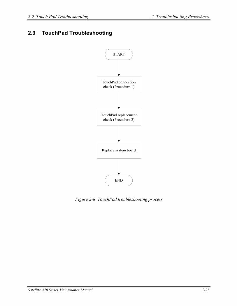
2.9 TouchPad Troubleshooting
START
END
TouchPad connectioncheck (Procedure 1)
TouchPad replacementcheck (Procedure 2)
Replace system board
Figure 2-8 TouchPad troubleshooting process
Satellite A70 Series Maintenance Manual 2-23

2 Troubleshooting Procedures 2.9 TouchPad Troubleshooting
To determine if the computer’s built-in TouchPad is functioning properly, perform the following procedures. Figure 2-9 outlines the process. Start with Procedure 1 and continue as instructed.
Procedure 1: TouchPad connection check
Procedure 2: TouchPad replacement check
Procedure 1 TouchPad connection check
The TouchPad is connected via the TouchPad FPC to the system board. Make sure the TouchPad FPC cable is firmly connected to the TouchPad and system board. Refer to Chapter 4, Replacement Procedures, for instructions on how to disassemble the computer and then perform the following checks.
If any of the connections are loose, reconnect firmly. If any of the connections is damaged, or there is still an error, go to Procedure 2.
Procedure 2 TouchPad replacement check
The TouchPad unit or FPC may be defective or damaged. Replace each with a new one following the steps in Chapter 4. If the FDD is still not functioning properly, replace the system board with a new one following the steps in Chapter 4.
2-24 Satellite A70 Series Maintenance Manual
2.10 Speaker Troubleshooting 2 Troubleshooting Procedures
2.10 Speaker Troubleshooting
START
Do all sources havesame problem?
END
Perform earphone test(Procedure 2)
Do earphonesfunction correctly?
Perform connection check(Procedure 3)
Perform replacementcheck
(Procedure 4)
Perform audio source test(Procedure 1)
No
Yes
Yes
Replace system board
Speakers are notfaulty. Continuetroubleshooting -
see Figure 2-1
No
Figure 2-9 Speaker troubleshooting process
Satellite A70 Series Maintenance Manual 2-25
2 Troubleshooting Procedures 2.10 Speaker Troubleshooting
2-26 Satellite A70 Series Maintenance Manual
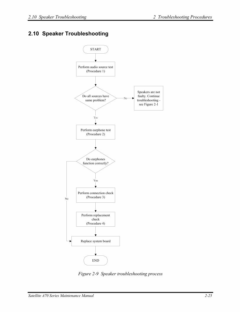
To determine if the computer’s built-in speakers are functioning properly, perform the following procedures. Figure 2-10 outlines the process. First adjust the speaker volume to an appropriate level. Start with Procedure 1 and continue as instructed.
Procedure 1: Audio source test
Procedure 2: Earphone test
Procedure 3: Connection check
Procedure 4: Replacement check
Procedure 1 Audio source test
Try different audio sources (e.g. an audio CD and digital music file) to determine whether the fault is in the speaker system or not. If not all sources have sound problem, the problem is in the source devices. If all have the same problem, continue with Procedure 2.
Procedure 2 Earphone test
Connect a set if earphones or external speakers. If these function correctly, go to Procedure 3. If they do not function correctly, the system board may be defective or damaged. Replace it with a new one.
Procedure 3 Connection check
Disassemble the computer following the steps described in Chapter 4, Replacement Procedures and make sure the speaker cable is firmly connected to the audio board. If the stereo speakers are still not functioning properly, go to Procedure 4.
Procedure 4 Replacement check
If the stereo speakers don't sound properly, the stereo speakers may be defective or damaged. Replace them with new ones. If the stereo speakers still do not work properly, try replacing in turn the audio board and system board.
Chapter 3 Tests and Diagnostics 3

3. Tests and Diagnostics
3-ii Satellite A70 Series Maintenance Manual
Test and Diagnostic Operation
Contents
3.1 The Diagnostic Test ......................................................................................................... 3-1
3.2 Executing the Diagnostic Test ......................................................................................... 3-2
3.3 Config Check Test ........................................................................................................... 3-6
3.4 DMI Check Test............................................................................................................... 3-7
3.5 PIO Loopback Test .......................................................................................................... 3-8
3.6 IEEE 1394 Test ................................................................................................................ 3-9
3.7 Speaker Audio Test........................................................................................................ 3-10
3.8 Fan ON/OFF Test .......................................................................................................... 3-11
3.9 Main Battery Charge Test.............................................................................................. 3-12
3.10 FDD Test........................................................................................................................ 3-13
3.11 CD-ROM Test................................................................................................................ 3-14
3.12 Keyboard Test................................................................................................................ 3-15
3.13 Mouse (Pad) Test ........................................................................................................... 3-17
3.14 LCD Pixels Mode Test .................................................................................................. 3-19
3.15 Lid Switch Test .............................................................................................................. 3-20
3.16 HDD R/W Test .............................................................................................................. 3-21
3.17 LAN Test ....................................................................................................................... 3-23
3.18 RTC Test........................................................................................................................ 3-25
3.19 CD Control Button Test ................................................................................................. 3-26
Satellite A70 Series Maintenance Manual 3-iii
3. Tests and Diagnostics
3-iv Satellite A70 Series Maintenance Manual

3.1 The Diagnostic Test 3. Tests and Diagnostics
3.1 The Diagnostic Test
This chapter explains how to use the Test & Diagnostic program to test the functions of the computer’s hardware modules. The Test & Diagnostic Program is stored on the T&D diskettes. The program consists of a series of tests that run automatically when the Diagnostics Program items are selected and executed.
NOTES: To start the diagnostics, follow these steps
1. Check all cables for loose connections.
2. Exit this program when you are at Main Menu.
The TEST & DIAGNOSTIC PROGRAM contains the following functional tests:
CONFIG CHECK TEST DMI CHECK TEST PIO LOOPBACK TEST IEEE1394 TEST SPEAKER AUDIO TEST FAN ON/OFF TEST MAIN BATTERY CHARGE TEST FDD TEST CD-ROM TEST KEYBOARD TEST MOUSE(PAD) TEST LCD PIXELS MODE TEST LID SWITCH TEST HDD R/W TEST LAN TEST RTC TEST
You will need the following equipment to perform some of the Diagnostic test programs.
The diagnostics diskette (2 pcs) A printer loopback connector (PIO Loopback Test) A formatted working diskette for the floppy disk drive test (Floppy Disk Drive Test) A data CD disc (CD-ROM Test) A LAN loopback connector (LAN Test) IEEE1394 Link Cable
The following sections explain how to execute the Test & Diagnostic Program and detail the tests within the program.
Satellite A70 Series Maintenance Manual 3-1
3. Tests and Diagnostics 3.2 Executing the Diagnostic Test
3.2 Executing the Diagnostic Test
Toshiba MS-DOS is required to run the DIAGNOSTICS PROGRAM. To start the DIAGNOSTIC PROGRAM, follow these steps:
1. Insert the diagnostics diskette #1 in the floppy disk drive and turn on the computer. (The diagnostics diskette contains the MS-DOS boot files.) And then follow the instructions to swap with the diagnostics diskette #2 for T&D program installed in RAM driver.
NOTE: To execute the CD test, make sure the CD is installed in the CD/DVD-ROM drive.
The T&D Program can run by single test item when you press corresponsive English letter of test item, or run two or more test items what you like if you choose them by “Arrow cursors” and “Space Bar” – the wonderful thing is you can setup test loop by “Enter” button. And it also asks you if you like to copy test log file to diskette as reference at the end of test(s).
The test list is as the following:
A. CONFIG CHECK TEST B. DMI CHECK TEST C. PIO LOOPBACK TEST D. RTC TEST E. LAN TEST F. SPEAKER AUDIO TEST G. FAN ON/OFF TEST H. MAIN BATTERY CHARGE TEST I. FDD TEST J. CD-ROM TEST K. KEYBOARD TEST L. MOUSE (PAD) TEST M. LCD PIXELS MODE TEST N. LID SWITCH TEST O. HDD R/W TEST P. D1 STEPPING TEST
3-2 Satellite A70 Series Maintenance Manual
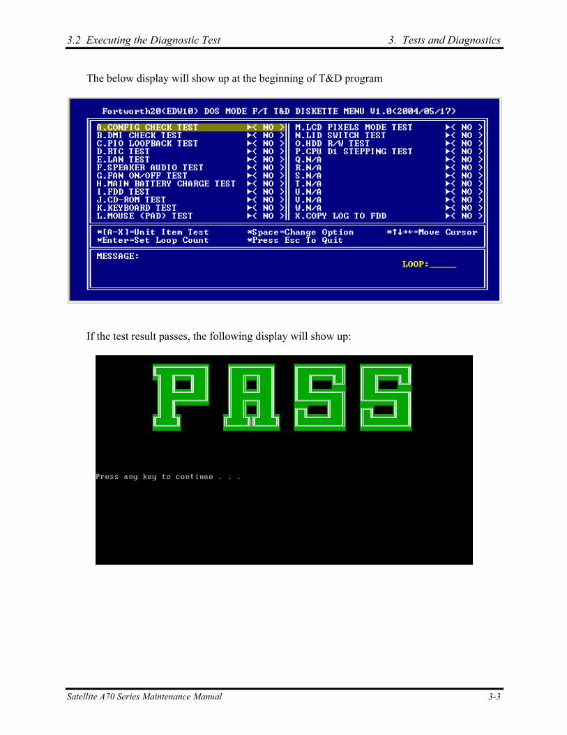
3.2 Executing the Diagnostic Test 3. Tests and Diagnostics
The below display will show up at the beginning of T&D program
If the test result passes, the following display will show up:
Satellite A70 Series Maintenance Manual 3-3

3. Tests and Diagnostics 3.2 Executing the Diagnostic Test
If an error is detected and a test fails, the following message displays:
Then press any key for next actions – the below display presented if copying test log file onto diskette is necessary. This action will be executed when “Y” key pressed.
3-4 Satellite A70 Series Maintenance Manual
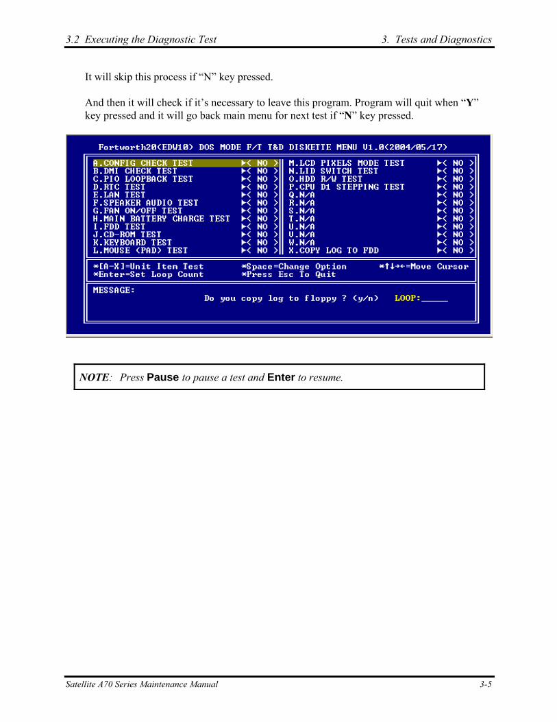
3.2 Executing the Diagnostic Test 3. Tests and Diagnostics
It will skip this process if “N” key pressed.
And then it will check if it’s necessary to leave this program. Program will quit when “Y” key pressed and it will go back main menu for next test if “N” key pressed.
NOTE: Press Pause to pause a test and Enter to resume.
Satellite A70 Series Maintenance Manual 3-5
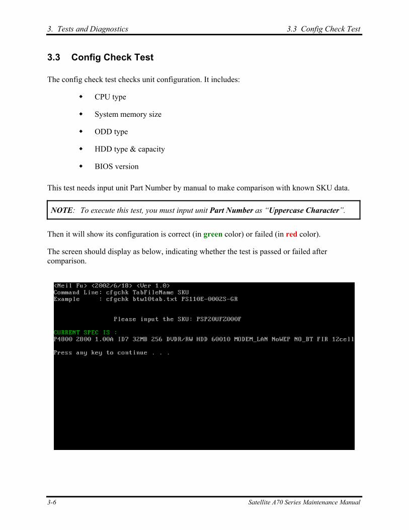
3. Tests and Diagnostics 3.3 Config Check Test
3.3 Config Check Test
The config check test checks unit configuration. It includes:
CPU type
System memory size
ODD type
HDD type & capacity
BIOS version
This test needs input unit Part Number by manual to make comparison with known SKU data.
NOTE: To execute this test, you must input unit Part Number as “Uppercase Character”.
Then it will show its configuration is correct (in green color) or failed (in red color).
The screen should display as below, indicating whether the test is passed or failed after comparison.
3-6 Satellite A70 Series Maintenance Manual
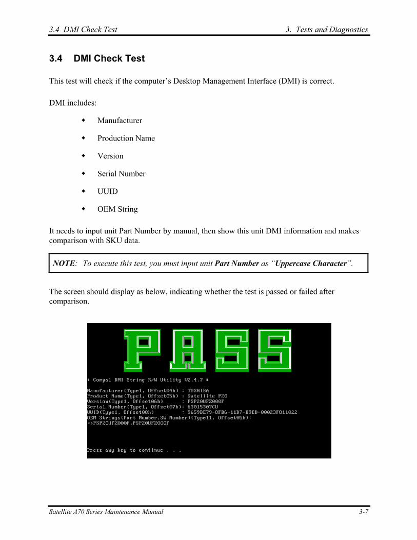
3.4 DMI Check Test 3. Tests and Diagnostics
3.4 DMI Check Test
This test will check if the computer’s Desktop Management Interface (DMI) is correct.
DMI includes:
Manufacturer
Production Name
Version
Serial Number
UUID
OEM String
It needs to input unit Part Number by manual, then show this unit DMI information and makes comparison with SKU data.
NOTE: To execute this test, you must input unit Part Number as “Uppercase Character”.
The screen should display as below, indicating whether the test is passed or failed after comparison.
Satellite A70 Series Maintenance Manual 3-7

3. Tests and Diagnostics 3.5 PIO Loopback Test
3.5 PIO Loopback Test
The PIO loopback test will check below items through PIO loopback connector.
External Interrupt
External Loopback
- including Pattern test, Data Pin test, Control register test & Control pin/ Status pin test.
NOTE: Remember to connect a PIO loopback connector to the computer's printer port before test begins.
The screen should display as below, indicating whether the test is passed or failed when finished.
3-8 Satellite A70 Series Maintenance Manual
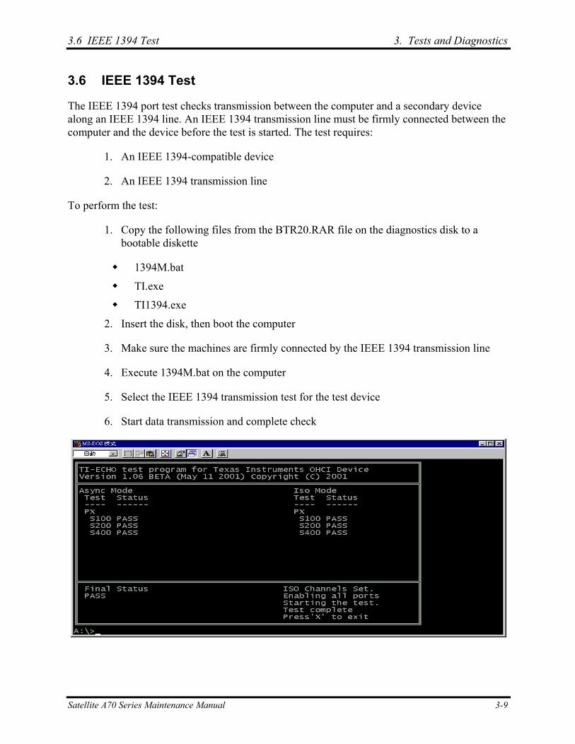
3.6 IEEE 1394 Test 3. Tests and Diagnostics
3.6 IEEE 1394 Test
The IEEE 1394 port test checks transmission between the computer and a secondary device along an IEEE 1394 line. An IEEE 1394 transmission line must be firmly connected between the computer and the device before the test is started. The test requires:
1. An IEEE 1394-compatible device
2. An IEEE 1394 transmission line
To perform the test:
1. Copy the following files from the BTR20.RAR file on the diagnostics disk to a bootable diskette
1394M.bat
TI.exe
TI1394.exe
2. Insert the disk, then boot the computer
3. Make sure the machines are firmly connected by the IEEE 1394 transmission line
4. Execute 1394M.bat on the computer
5. Select the IEEE 1394 transmission test for the test device
6. Start data transmission and complete check
Satellite A70 Series Maintenance Manual 3-9
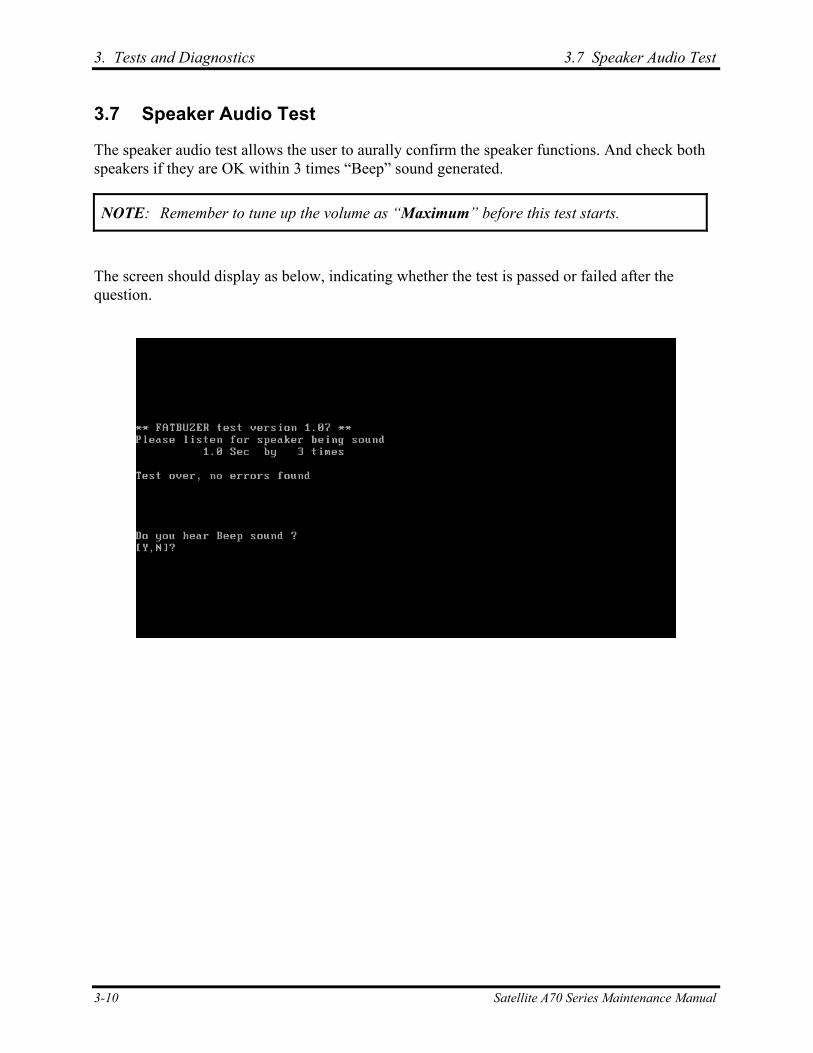
3. Tests and Diagnostics 3.7 Speaker Audio Test
3.7 Speaker Audio Test
The speaker audio test allows the user to aurally confirm the speaker functions. And check both speakers if they are OK within 3 times “Beep” sound generated.
NOTE: Remember to tune up the volume as “Maximum” before this test starts.
The screen should display as below, indicating whether the test is passed or failed after the question.
3-10 Satellite A70 Series Maintenance Manual

3.8 Fan ON/OFF Test 3. Tests and Diagnostics
3.8 Fan ON/OFF Test
The fan test allows the user to test aurally whether the fan is working. And follow the below procedures for this test:
The computer will let the fan be “ON” after any key pressed. Listen to check whether the fan is working.
NOTE: Remember to approach fan outlet that is near right side of unit whether fan is “ON”.
The computer will stop the fan working after any key pressed. Listen to check if the fan is “OFF” – it means no rotating sound.
The screen should display as below, indicating whether the test is passed or failed after the question.
Satellite A70 Series Maintenance Manual 3-11
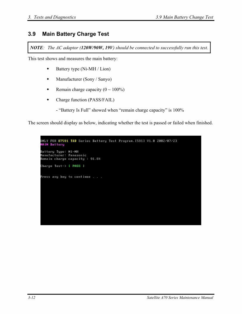
3. Tests and Diagnostics 3.9 Main Battery Change Test
3.9 Main Battery Charge Test
NOTE: The AC adaptor (120W/90W, 19V) should be connected to successfully run this test.
This test shows and measures the main battery:
Battery type (Ni-MH / Lion)
Manufacturer (Sony / Sanyo)
Remain charge capacity (0 ~ 100%)
Charge function (PASS/FAIL)
- “Battery Is Full” showed when “remain charge capacity” is 100%
The screen should display as below, indicating whether the test is passed or failed when finished.
3-12 Satellite A70 Series Maintenance Manual
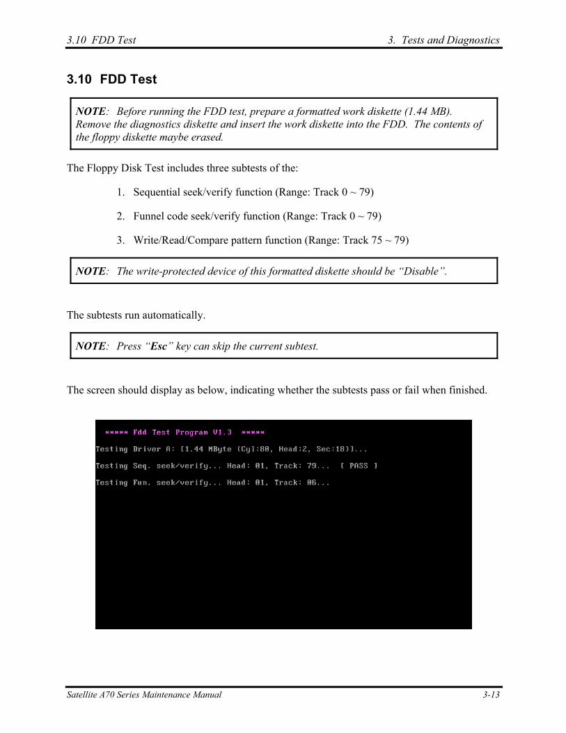
3.10 FDD Test 3. Tests and Diagnostics
3.10 FDD Test
NOTE: Before running the FDD test, prepare a formatted work diskette (1.44 MB). Remove the diagnostics diskette and insert the work diskette into the FDD. The contents of the floppy diskette maybe erased.
The Floppy Disk Test includes three subtests of the:
1. Sequential seek/verify function (Range: Track 0 ~ 79)
2. Funnel code seek/verify function (Range: Track 0 ~ 79)
3. Write/Read/Compare pattern function (Range: Track 75 ~ 79)
NOTE: The write-protected device of this formatted diskette should be “Disable”.
The subtests run automatically.
NOTE: Press “Esc” key can skip the current subtest.
The screen should display as below, indicating whether the subtests pass or fail when finished.
Satellite A70 Series Maintenance Manual 3-13
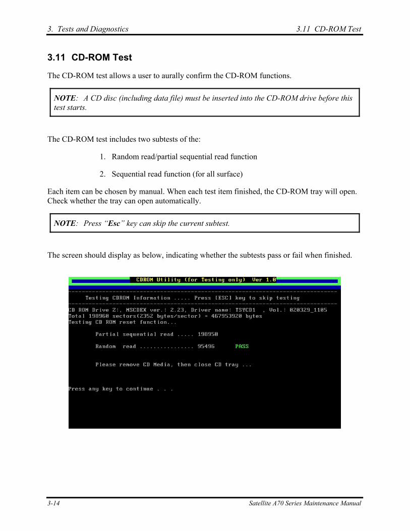
3. Tests and Diagnostics 3.11 CD-ROM Test
3.11 CD-ROM Test
The CD-ROM test allows a user to aurally confirm the CD-ROM functions.
NOTE: A CD disc (including data file) must be inserted into the CD-ROM drive before this test starts.
The CD-ROM test includes two subtests of the:
1. Random read/partial sequential read function
2. Sequential read function (for all surface)
Each item can be chosen by manual. When each test item finished, the CD-ROM tray will open. Check whether the tray can open automatically.
NOTE: Press “Esc” key can skip the current subtest.
The screen should display as below, indicating whether the subtests pass or fail when finished.
3-14 Satellite A70 Series Maintenance Manual
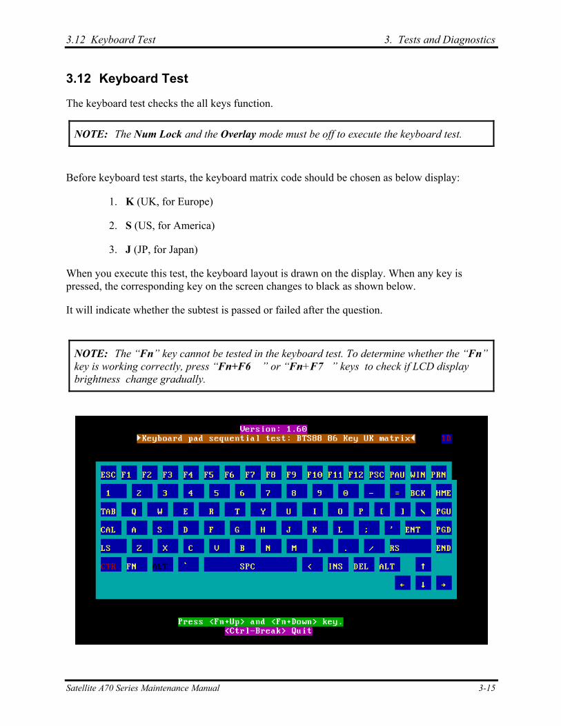
3.12 Keyboard Test 3. Tests and Diagnostics
3.12 Keyboard Test
The keyboard test checks the all keys function.
NOTE: The Num Lock and the Overlay mode must be off to execute the keyboard test.
Before keyboard test starts, the keyboard matrix code should be chosen as below display:
1. K (UK, for Europe)
2. S (US, for America)
3. J (JP, for Japan)
When you execute this test, the keyboard layout is drawn on the display. When any key is pressed, the corresponding key on the screen changes to black as shown below.
It will indicate whether the subtest is passed or failed after the question.
NOTE: The “Fn” key cannot be tested in the keyboard test. To determine whether the “Fn” key is working correctly, press “Fn+F6 ” or “Fn+F7 ” keys to check if LCD display brightness change gradually.
Satellite A70 Series Maintenance Manual 3-15
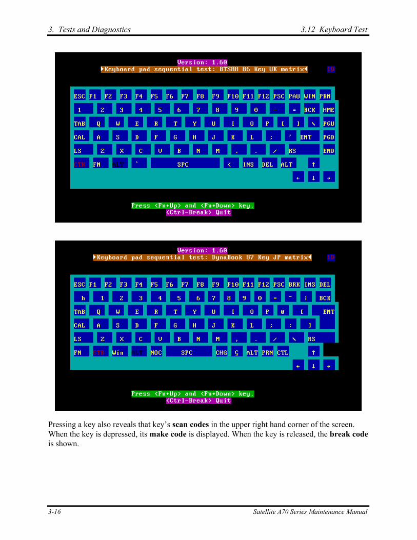
3. Tests and Diagnostics 3.12 Keyboard Test
Pressing a key also reveals that key’s scan codes in the upper right hand corner of the screen. When the key is depressed, its make code is displayed. When the key is released, the break code is shown.
3-16 Satellite A70 Series Maintenance Manual
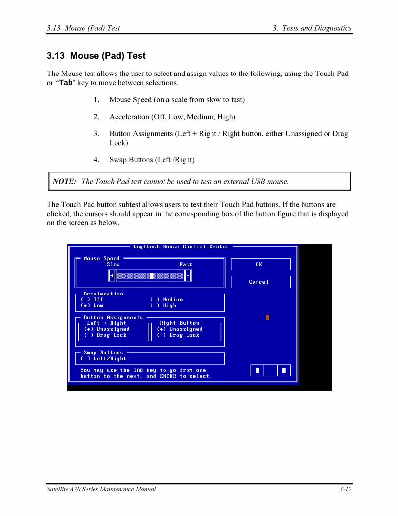
3.13 Mouse (Pad) Test 3. Tests and Diagnostics
3.13 Mouse (Pad) Test
The Mouse test allows the user to select and assign values to the following, using the Touch Pad or “Tab” key to move between selections:
1. Mouse Speed (on a scale from slow to fast)
2. Acceleration (Off, Low, Medium, High)
3. Button Assignments (Left + Right / Right button, either Unassigned or Drag Lock)
4. Swap Buttons (Left /Right)
NOTE: The Touch Pad test cannot be used to test an external USB mouse.
The Touch Pad button subtest allows users to test their Touch Pad buttons. If the buttons are clicked, the cursors should appear in the corresponding box of the button figure that is displayed on the screen as below.
Satellite A70 Series Maintenance Manual 3-17
3. Tests and Diagnostics 3.13 Mouse (Pad) Test
After checking T/Pad buttons and cursor’s function, use “Tab” key or use T/Pad cursor to click the “OK” column will end this test.
It will indicate whether the subtests pass or fail after three questions.
NOTE: The above figure has three compartments although the Touch Pad installed may only have two buttons. In this case, the central compartment in the figure does not correspond to any button.
3-18 Satellite A70 Series Maintenance Manual
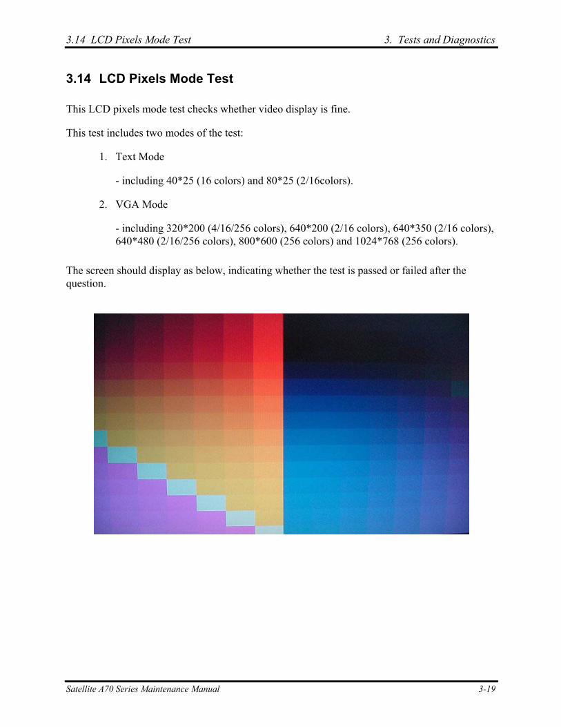
3.14 LCD Pixels Mode Test 3. Tests and Diagnostics
3.14 LCD Pixels Mode Test
This LCD pixels mode test checks whether video display is fine.
This test includes two modes of the test:
1. Text Mode
- including 40*25 (16 colors) and 80*25 (2/16colors).
2. VGA Mode
- including 320*200 (4/16/256 colors), 640*200 (2/16 colors), 640*350 (2/16 colors), 640*480 (2/16/256 colors), 800*600 (256 colors) and 1024*768 (256 colors).
The screen should display as below, indicating whether the test is passed or failed after the question.
Satellite A70 Series Maintenance Manual 3-19
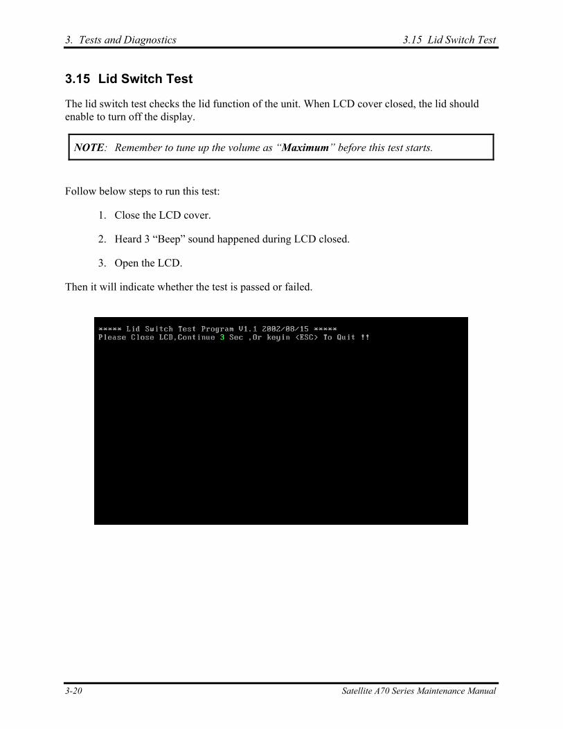
3. Tests and Diagnostics 3.15 Lid Switch Test
3.15 Lid Switch Test
The lid switch test checks the lid function of the unit. When LCD cover closed, the lid should enable to turn off the display.
NOTE: Remember to tune up the volume as “Maximum” before this test starts.
Follow below steps to run this test:
1. Close the LCD cover.
2. Heard 3 “Beep” sound happened during LCD closed.
3. Open the LCD.
Then it will indicate whether the test is passed or failed.
3-20 Satellite A70 Series Maintenance Manual

3.16 HDD R/W Test 3. Tests and Diagnostics
3.16 HDD R/W Test
The HDD R/W test allows the user to test aurally HDD read/write function. For data security concern, it is necessary to input password - “TOSHIBA” before HDD write test starts.
The HDD test includes three subtests of the:
1. Sequential read (all surface)
2. Sequential write (all surface)
3. Partial W/R + Random W/R
After the choice is made, HDD information will show as below:
Model name
Firmware revision
Serial number
CHR (Cylinder High Register) mode – including cylinders, heads, sectors and sizes.
LBA (Logical Block Addressing) mode – including sectors and sizes.
Support Ultra DMA Mode
Support PIO Mode
Satellite A70 Series Maintenance Manual 3-21
3. Tests and Diagnostics 3.16 HDD R/W Test
NOTE: Press “Ctrl + Break” keys can terminate the current subtest.
The screen should display as previous picture, indicating whether the subtest is passed or failed when finished.
NOTE: The AC adaptor should be connected to successfully run this test.
3-22 Satellite A70 Series Maintenance Manual
3.17 LAN Test 3. Tests and Diagnostics
3.17 LAN Test
The LAN test checks the LAN full-duplex environment.
NOTE: LAN loopback needs to plug in before test begins.
And LAN information will show on the test screen:
IO Base – Port: 3000H
IRQ – AH, it’s “IRQ 10”.
Node – it is “MAC Address”.
Line Frame – 1514 Bytes.
Line Speed – 100Mbps or 10 Mbps.
Bus ID – it’s “4”.
The LAN test includes two subtests of the:
1. Speed100
- including Ethernet_802.2, Ethernet_II, Ethernet_SNAP and Ethernet_802.3. All test items are in LSB mode.
2. Speed10
- including Ethernet_802.2 in LSB mode.
The subtests run automatically.
Satellite A70 Series Maintenance Manual 3-23
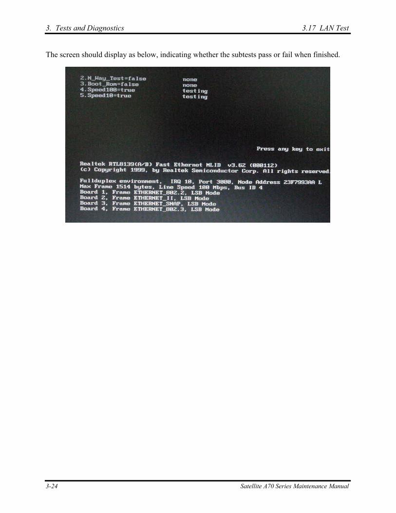
3. Tests and Diagnostics 3.17 LAN Test
The screen should display as below, indicating whether the subtests pass or fail when finished.
3-24 Satellite A70 Series Maintenance Manual
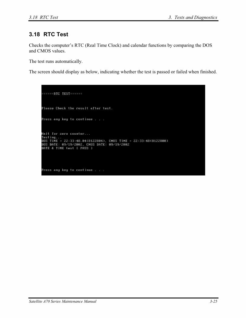
3.18 RTC Test 3. Tests and Diagnostics
3.18 RTC Test
Checks the computer’s RTC (Real Time Clock) and calendar functions by comparing the DOS and CMOS values.
The test runs automatically.
The screen should display as below, indicating whether the test is passed or failed when finished.
Satellite A70 Series Maintenance Manual 3-25
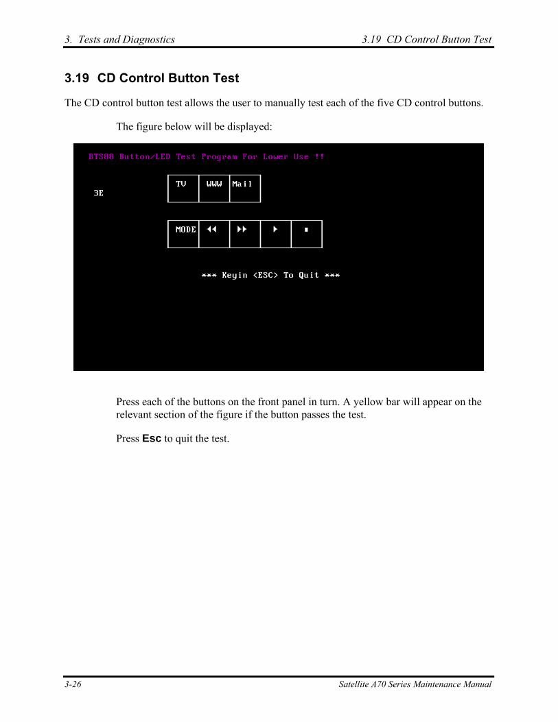
3. Tests and Diagnostics 3.19 CD Control Button Test
3.19 CD Control Button Test
The CD control button test allows the user to manually test each of the five CD control buttons.
The figure below will be displayed:
Press each of the buttons on the front panel in turn. A yellow bar will appear on the relevant section of the figure if the button passes the test.
Press Esc to quit the test.
3-26 Satellite A70 Series Maintenance Manual
Chapter 4 Replacement Procedures 4

4 Replacement Procedures
4-ii Satellite P10 PSP13*/16* Series Maintenance Manual
4 Replacement Procedures
Chapter 4 Contents
4.1 General............................................................................................................................. 4-1
4.2 Battery.............................................................................................................................. 4-7
4.3 PC Card............................................................................................................................ 4-9
4.4 HDD............................................................................................................................... 4-11
4.5 Optical Drive Module .................................................................................................... 4-13
4.6 Optical Drive.................................................................................................................. 4-15
4.7 Wireless LAN Unit ........................................................................................................ 4-17
4.8 Expansion Memory........................................................................................................ 4-20
4.9 Keyboard........................................................................................................................ 4-23
4.10 Modem ........................................................................................................................... 4-26
4.11 Display Assembly .......................................................................................................... 4-28
4.12 Touch Cover................................................................................................................... 4-31
4.13 Touch Pad ...................................................................................................................... 4-34
4.14 Speakers ......................................................................................................................... 4-36
4.15 System Board ................................................................................................................. 4-37
4.16 Fan, Heat Sink, & CPU.................................................................................................. 4-39
4.17 Display Mask ................................................................................................................. 4-42
4.18 LCD Module .................................................................................................................. 4-44
4.19 FL Inverter Board .......................................................................................................... 4-47
Satellite P10 PSP13*/16* Series Maintenance Manual 4-iii
4 Replacement Procedures
4-iv Satellite P10 PSP13*/16* Series Maintenance Manual
Figures
Figure 4-1 Removing the battery pack ...................................................................................4-7 Figure 4-2 Pressing the eject button .......................................................................................4-9 Figure 4-3 Installing the PC Card.........................................................................................4-10 Figure 4-4 HDD....................................................................................................................4-11 Figure 4-5 Removing the HDD door ....................................................................................4-11 Figure 4-6 Removing the optical drive module ....................................................................4-13 Figure 4-7 Removing the optical drive bracket ....................................................................4-15 Figure 4-8 Removing the mini PCI bracket..........................................................................4-17 Figure 4-9 Removing the wireless LAN unit........................................................................4-18 Figure 4-10 Removing the expansion memory.......................................................................4-20 Figure 4-11 Removing the expansion memory cover.............................................................4-21 Figure 4-12 Installing the expansion memory ........................................................................4-22 Figure 4-13 Removing the strip cover ....................................................................................4-23 Figure 4-14 Removing the keyboard ......................................................................................4-24 Figure 4-15 Disconnecting the keyboard cable ......................................................................4-25 Figure 4-16 Removing the modem module ............................................................................4-26 Figure 4-17 Removing the LCD display cable .......................................................................4-29 Figure 4-18 Pulling the wireless LAN antenna wires.............................................................4-29 Figure 4-19 Removing the top cover-1...................................................................................4-31 Figure 4-20 Removing the top cover-2...................................................................................4-32 Figure 4-21 Removing the touch pad .....................................................................................4-34 Figure 4-22 Removing the speakers .......................................................................................4-36 Figure 4-23 Removing the system board-1.............................................................................4-37 Figure 4-24 Removing the system board-2.............................................................................4-37 Figure 4-25 Removing the fan module ...................................................................................4-39 Figure 4-26 Removing the heat sink.......................................................................................4-40 Figure 4-27 Removing the CPU .............................................................................................4-40 Figure 4-28 Removing the display mask ................................................................................4-42 Figure 4-29 Removing the LCD module-1.............................................................................4-44 Figure 4-30 Removing the LCD module-2.............................................................................4-45 Figure 4-31 Removing the FL inverter board.........................................................................4-47
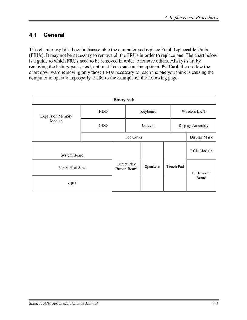
4 Replacement Procedures
4
4.1 General
This chapter explains how to disassemble the computer and replace Field Replaceable Units (FRUs). It may not be necessary to remove all the FRUs in order to replace one. The chart below is a guide to which FRUs need to be removed in order to remove others. Always start by removing the battery pack, next, optional items such as the optional PC Card, then follow the chart downward removing only those FRUs necessary to reach the one you think is causing the computer to operate improperly. Refer to the example on the following page.
Battery pack
HDD Keyboard Wireless LAN
ODD Modem Display Assembly
Expansion Memory Module
Top Cover Display Mask
System Board LCD Module
Fan & Heat Sink
CPU
Direct Play Button Board Speakers Touch Pad
FL Inverter Board
Satellite A70 Series Maintenance Manual 4-1
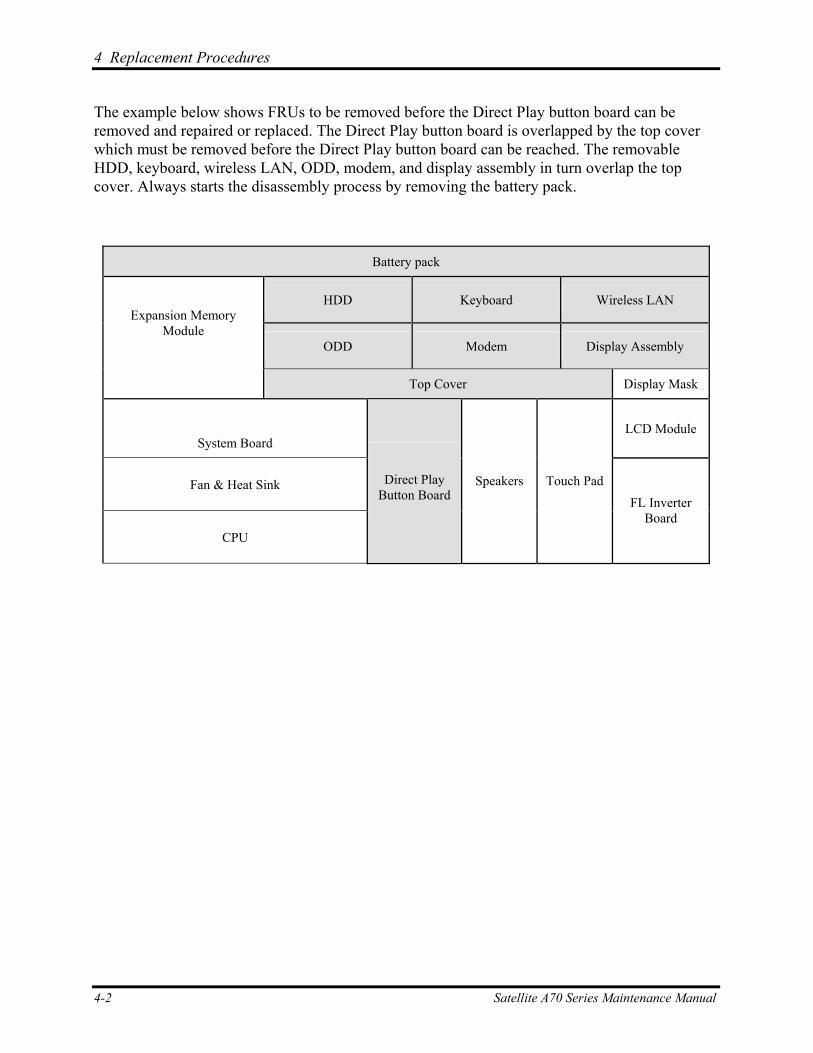
4 Replacement Procedures
The example below shows FRUs to be removed before the Direct Play button board can be removed and repaired or replaced. The Direct Play button board is overlapped by the top cover which must be removed before the Direct Play button board can be reached. The removable HDD, keyboard, wireless LAN, ODD, modem, and display assembly in turn overlap the top cover. Always starts the disassembly process by removing the battery pack.
Battery pack
HDD Keyboard Wireless LAN
ODD Modem Display Assembly
Expansion Memory Module
Top Cover Display Mask
System Board LCD Module
Fan & Heat Sink
CPU
Direct Play Button Board
Speakers Touch Pad FL Inverter
Board
4-2 Satellite A70 Series Maintenance Manual
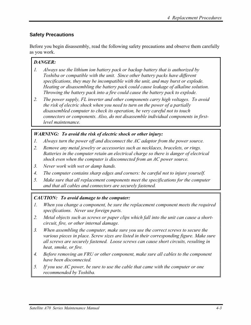
4 Replacement Procedures
Safety Precautions
Before you begin disassembly, read the following safety precautions and observe them carefully as you work.
DANGER: 1. Always use the lithium ion battery pack or backup battery that is authorized by
Toshiba or compatible with the unit. Since other battery packs have different specifications, they may be incompatible with the unit, and may burst or explode. Heating or disassembling the battery pack could cause leakage of alkaline solution. Throwing the battery pack into a fire could cause the battery pack to explode.
2. The power supply, FL inverter and other components carry high voltages. To avoid the risk of electric shock when you need to turn on the power of a partially disassembled computer to check its operation, be very careful not to touch connectors or components. Also, do not disassemble individual components in first-level maintenance.
WARNING: To avoid the risk of electric shock or other injury: 1. Always turn the power off and disconnect the AC adaptor from the power source. 2. Remove any metal jewelry or accessories such as necklaces, bracelets, or rings.
Batteries in the computer retain an electrical charge so there is danger of electrical shock even when the computer is disconnected from an AC power source.
3. Never work with wet or damp hands. 4. The computer contains sharp edges and corners: be careful not to injure yourself. 5. Make sure that all replacement components meet the specifications for the computer
and that all cables and connectors are securely fastened.
CAUTION: To avoid damage to the computer: 1. When you change a component, be sure the replacement component meets the required
specifications. Never use foreign parts. 2. Metal objects such as screws or paper clips which fall into the unit can cause a short-
circuit, fire, or other internal damage. 3. When assembling the computer, make sure you use the correct screws to secure the
various pieces in place. Screw sizes are listed in their corresponding figure. Make sure all screws are securely fastened. Loose screws can cause short circuits, resulting in heat, smoke, or fire.
4. Before removing an FRU or other component, make sure all cables to the component have been disconnected.
5. If you use AC power, be sure to use the cable that came with the computer or one recommended by Toshiba.
Satellite A70 Series Maintenance Manual 4-3
4 Replacement Procedures
Before You Begin
Look over the procedures in this section before you begin disassembling the computer. Familiarize yourself with the disassembly and reassembly steps. Begin each procedure by removing the AC adaptor and the battery pack as instructed in section 4.2.
1. Do not disassemble the computer unless it is operating abnormally.
2. Use only the correct and approved tools.
3. Make sure the working environment is free from the following elements whether you are using or storing the computer.
Dust and contaminates Static electricity Extreme heat, cold and humidity
4. Make sure the FRU you are replacing is causing the abnormal operation by performing the necessary troubleshooting and diagnostics tests described in chapters 2 and 3 of this manual.
5. Do not perform any operations that are not necessary and use only the described procedures for disassembling and installing FRUs in the computer.
6. After removing parts from the computer, place them in a safe place away from the computer so they will not be damaged and will not interfere with your work.
7. You will remove and replace many screws when you disassemble the computer. When you remove screws, make sure they are placed in a safe place and identified with the correct parts.
8. When assembling the computer make sure you use the correct screws to secure the various pieces. Screw sizes are listed in their corresponding figures.
9. The computer contains many sharp edges and corners, so be careful not to injure yourself.
10. After you have replaced an FRU, make sure the computer is functioning properly by performing the appropriate test on the FRU you have fixed or replaced.
4-4 Satellite A70 Series Maintenance Manual
4 Replacement Procedures
Disassembly Procedures
The computer has two basic types of cable connectors:
Pressure Plate Connectors Standard Pin Connectors
To disconnect a Pressure Plate connector, lift up the tabs on either side of the connector’s plastic pressure plate and slide the cable out of the connector. To connect the cable to a Pressure Plate connector, make sure the pressure plate is fully lifted and slide the cable into the connector. Secure the cable in place by pushing the sides of the pressure plate down so the plate is flush with the sides of the connector. Gently pull on the cable to make sure the cable is secure. If you pull out the connector, connect it again making sure the connector’s pressure plate is fully lifted when you insert the cable.
Standard pin connectors are used with all other cables. These connectors can be connected and disconnected by simply pulling them apart or pushing them together.
Assembly Procedures
After you have disassembled the computer and fixed or repaired the problem that was causing the computer to operate abnormally, you will need to reassemble the computer.
Install all the removed FRUs following the steps described in the corresponding sections in this chapter.
While assembling the computer, remember the following general points:
Take your time, making sure you follow the instructions closely. Most problems arise when you get in a hurry assembling the computer.
Make sure all cables and connectors are securely fastened.
Before securing the FRU or other parts, make sure that no cables will be pinched by screws or the FRU.
Check that all latches are closed securely.
Make sure all the correct screws are used to secure all FRUs. Using the wrong screw can either damage the threads on the screw or the head of the screw and may prevent proper seating of an FRU.
After installing an FRU in the computer, confirm that the FRU and the computer are functioning properly.
Satellite A70 Series Maintenance Manual 4-5
4 Replacement Procedures
Tools and Equipment
The use of Electrostatic Discharge (ESD) equipment is very important for your safety and the safety of those around you. Proper use of these devices will increase the success rate of your repairs and lower the cost for damaged or destroyed parts. The following equipment is necessary to disassemble and reassemble the computer:
One M2 Phillips screwdriver to remove and replace screws.
One T5 security screwdriver.
Tweezers, to lift out screws that you cannot grasp with your fingers.
ESD mats for the floor and the table you are working on.
ESD wrist strap or heel grounder.
Anti-static carpeting or flooring.
Air-ionizers in highly static sensitive areas.
4-6 Satellite A70 Series Maintenance Manual
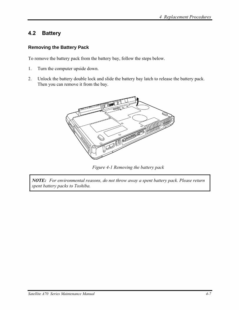
4 Replacement Procedures
4.2 Battery
Removing the Battery Pack
To remove the battery pack from the battery bay, follow the steps below.
1. Turn the computer upside down.
2. Unlock the battery double lock and slide the battery bay latch to release the battery pack. Then you can remove it from the bay.
Figure 4-1 Removing the battery pack
NOTE: For environmental reasons, do not throw away a spent battery pack. Please return spent battery packs to Toshiba.
Satellite A70 Series Maintenance Manual 4-7
4 Replacement Procedures
Installing the Battery Pack
To install the battery pack in the battery bay, follow the steps below and refer to the figure in the preceding section.
WARNING: The battery is a lithium ion battery and can explode if not properly replaced, used, handled or disposed of. Use only batteries recommended by Toshiba as replacements.
1. Slide the battery pack into the battery bay. The battery bay latch will click automatically.
2. Lock the battery double lock to secure the battery pack in position.
4-8 Satellite A70 Series Maintenance Manual

4 Replacement Procedures
4.3 PC Card
Removing a PC Card
To remove a PC Card, follow the steps below.
1. Push the PC Card’s eject button. The button pops out when you release it.
2. Push the eject button once more to pop the PC Card out slightly.
3. Grasp the PC Card and remove it.
4. Push the eject button back into place, if necessary.
ReWritable
High Speed
Figure 4-2 Pressing the eject button
Satellite A70 Series Maintenance Manual 4-9
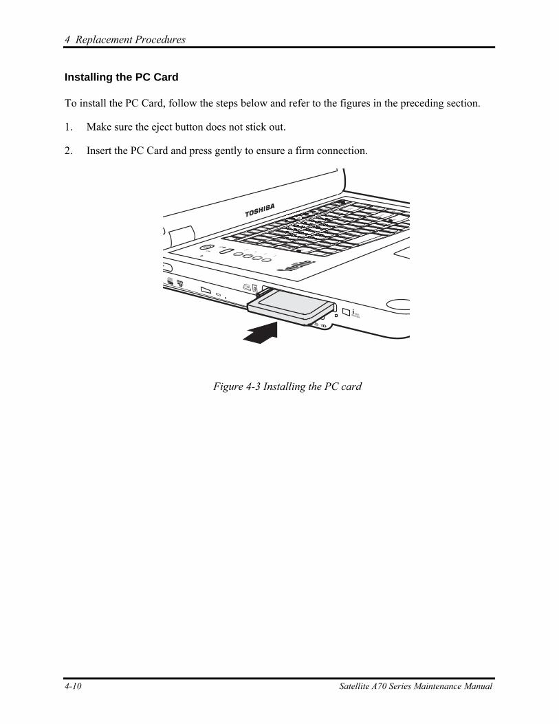
4 Replacement Procedures
Installing the PC Card
To install the PC Card, follow the steps below and refer to the figures in the preceding section.
1. Make sure the eject button does not stick out.
2. Insert the PC Card and press gently to ensure a firm connection.
ReWritable
High Speed
Figure 4-3 Installing the PC card
4-10 Satellite A70 Series Maintenance Manual
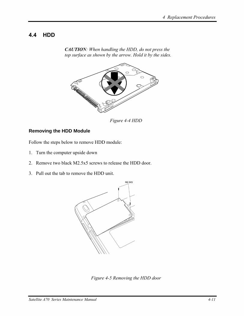
4 Replacement Procedures
4.4 HDD
CAUTION: When handling the HDD, do not press the top surface as shown by the arrow. Hold it by the sides.
Figure 4-4 HDD
Removing the HDD Module
Follow the steps below to remove HDD module:
1.
2.
3.
Turn the computer upside down
Remove two black M2.5x5 screws to release the HDD door.
Pull out the tab to remove the HDD unit.
Figure 4-5 Removing the HDD door
Satellite A70 Series Maintenance Manual 4-11
4 Replacement Procedures
4.
5.
Remove the four M3x3 silver screws that secure the HDD case and bracket to the HDD.
Remove the HDD from the HDD case.
Installing the HDD
To install the HDD, follow the steps below and refer to the figures in the preceding section.
1. Seat the HDD in the HDD case and bracket, and secure it with four M3×3 silver screws.
2. Insert the HDD unit into the HDD slot.
3. Secure the HDD door with two black M2.5x5 screws.
4-12 Satellite A70 Series Maintenance Manual
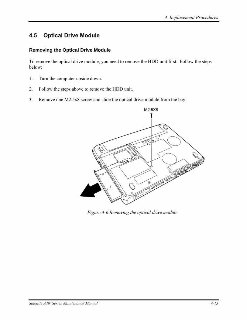
4 Replacement Procedures
4.5 Optical Drive Module
Removing the Optical Drive Module
To remove the optical drive module, you need to remove the HDD unit first. Follow the steps below:
1. Turn the computer upside down.
2. Follow the steps above to remove the HDD unit.
3. Remove one M2.5x8 screw and slide the optical drive module from the bay.
Figure 4-6 Removing the optical drive module
Satellite A70 Series Maintenance Manual 4-13
4 Replacement Procedures
Installing the Optical Drive Module
To install a device in the optical drive module bay, follow the steps below and refer to the figure in the preceding section.
1. Slide the device into the optical drive module bay. Use one M2.5x8 screw to secure it in position.
2. Slide HDD into the HDD bay.
3. Replace the HDD door and use two black M2.5x5 screws to secure it in position.
4-14 Satellite A70 Series Maintenance Manual
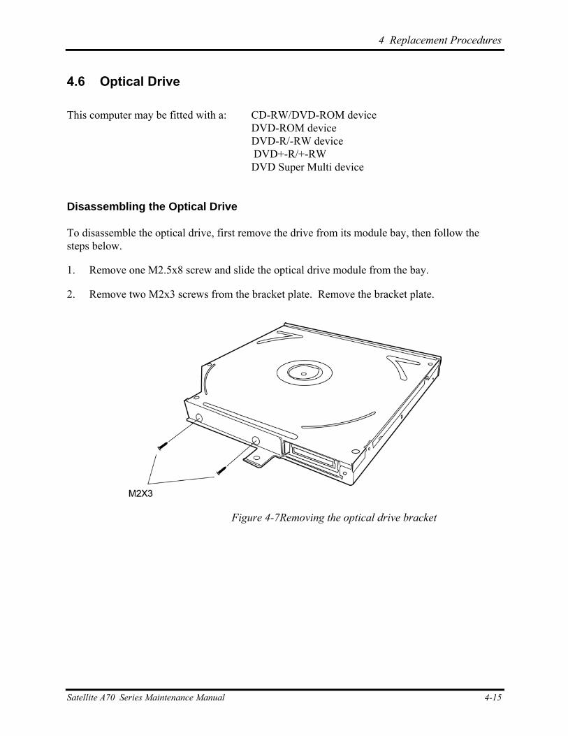
4 Replacement Procedures
4.6 Optical Drive
This computer may be fitted with a: CD-RW/DVD-ROM device DVD-ROM device DVD-R/-RW device
DVD+-R/+-RW DVD Super Multi device
Disassembling the Optical Drive
To disassemble the optical drive, first remove the drive from its module bay, then follow the steps below.
1. Remove one M2.5x8 screw and slide the optical drive module from the bay.
2. Remove two M2x3 screws from the bracket plate. Remove the bracket plate.
Figure 4-7Removing the optical drive bracket
Satellite A70 Series Maintenance Manual 4-15
4 Replacement Procedures
Reassembling the Optical Drive
To reassemble an optical drive, follow the steps below and refer to the figure in the preceding section.
1. Position the optical drive bracket plate to the rear panel of optical drive.
2. Secure the optical drive bracket plate with two black M2×3 screws.
3. Install the optical drive module into the bay and secure with one M2.5x8 screw.
4-16 Satellite A70 Series Maintenance Manual
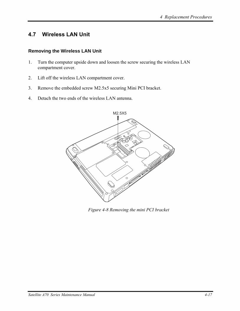
4 Replacement Procedures
4.7 Wireless LAN Unit
Removing the Wireless LAN Unit
1. Turn the computer upside down and loosen the screw securing the wireless LAN compartment cover.
2. Lift off the wireless LAN compartment cover.
3. Remove the embedded screw M2.5x5 securing Mini PCI bracket.
4. Detach the two ends of the wireless LAN antenna.
M2.5X5
Figure 4-8 Removing the mini PCI bracket
Satellite A70 Series Maintenance Manual 4-17
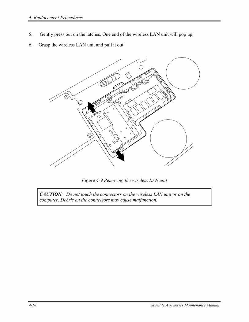
4 Replacement Procedures
5. Gently press out on the latches. One end of the wireless LAN unit will pop up.
6. Grasp the wireless LAN unit and pull it out.
Figure 4-9 Removing the wireless LAN unit
CAUTION: Do not touch the connectors on the wireless LAN unit or on the computer. Debris on the connectors may cause malfunction.
4-18 Satellite A70 Series Maintenance Manual
4 Replacement Procedures
Installing the Wireless LAN Unit
To install the wireless LAN unit, follow the steps below and refer to the figures in the preceding section.
1. Turn the computer upside down and loosen the screw securing the wireless LAN compartment cover.
2. Lift off the wireless LAN compartment cover.
3. Fit the wireless LAN unit’s connector to the computer’s connectors and press carefully to ensure firm contact.
CAUTION: Do not touch the connectors on the wireless LAN unit or on the computer. Debris on the connectors may cause malfunction.
4. Gently, push the wireless LAN unit down until the latches engage the unit to hold it in place.
5. Attach the ends of the wireless LAN antenna. The black antenna cable should be attached to the connector near the rear side of the computer, the white antenna cable to the connector closer to the front panel.
6. Use the screw M2.5x5 to secure the Mini PCI bracket.
7. Seat the wireless LAN compartment cover and secure it with the embedded security screw.
Satellite A70 Series Maintenance Manual 4-19
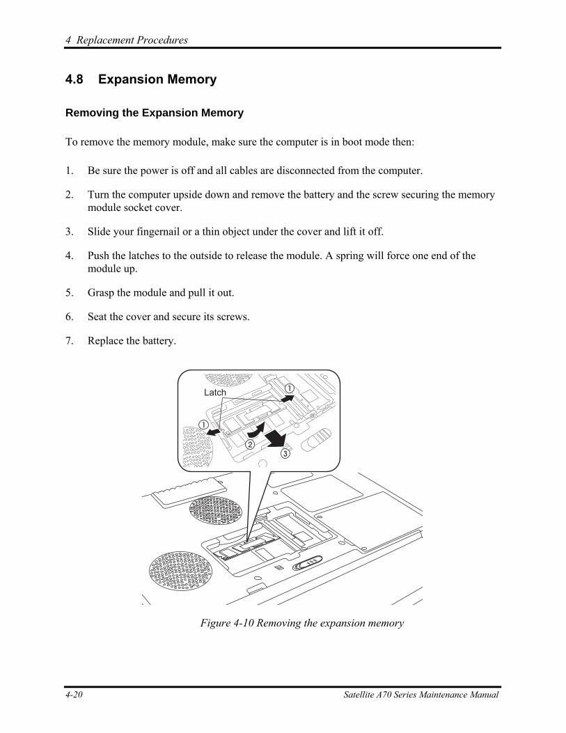
4 Replacement Procedures
4.8 Expansion Memory
Removing the Expansion Memory
To remove the memory module, make sure the computer is in boot mode then: 1. Be sure the power is off and all cables are disconnected from the computer.
2. Turn the computer upside down and remove the battery and the screw securing the memory module socket cover.
3. Slide your fingernail or a thin object under the cover and lift it off.
4. Push the latches to the outside to release the module. A spring will force one end of the module up.
5. Grasp the module and pull it out.
6. Seat the cover and secure its screws.
7. Replace the battery.
Latch
1
2
1
3
Figure 4-10 Removing the expansion memory
4-20 Satellite A70 Series Maintenance Manual
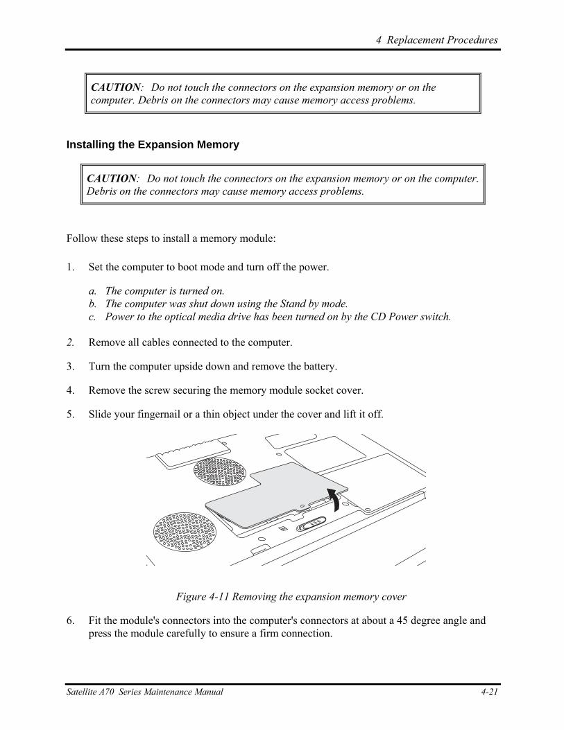
4 Replacement Procedures
CAUTION: Do not touch the connectors on the expansion memory or on the computer. Debris on the connectors may cause memory access problems.
Installing the Expansion Memory
CAUTION: Do not touch the connectors on the expansion memory or on the computer. Debris on the connectors may cause memory access problems.
Follow these steps to install a memory module: 1. Set the computer to boot mode and turn off the power.
a. The computer is turned on. b. The computer was shut down using the Stand by mode. c. Power to the optical media drive has been turned on by the CD Power switch.
2. Remove all cables connected to the computer.
3. Turn the computer upside down and remove the battery.
4. Remove the screw securing the memory module socket cover.
5. Slide your fingernail or a thin object under the cover and lift it off.
Figure 4-11 Removing the expansion memory cover
6. Fit the module's connectors into the computer's connectors at about a 45 degree angle and press the module carefully to ensure a firm connection.
Satellite A70 Series Maintenance Manual 4-21
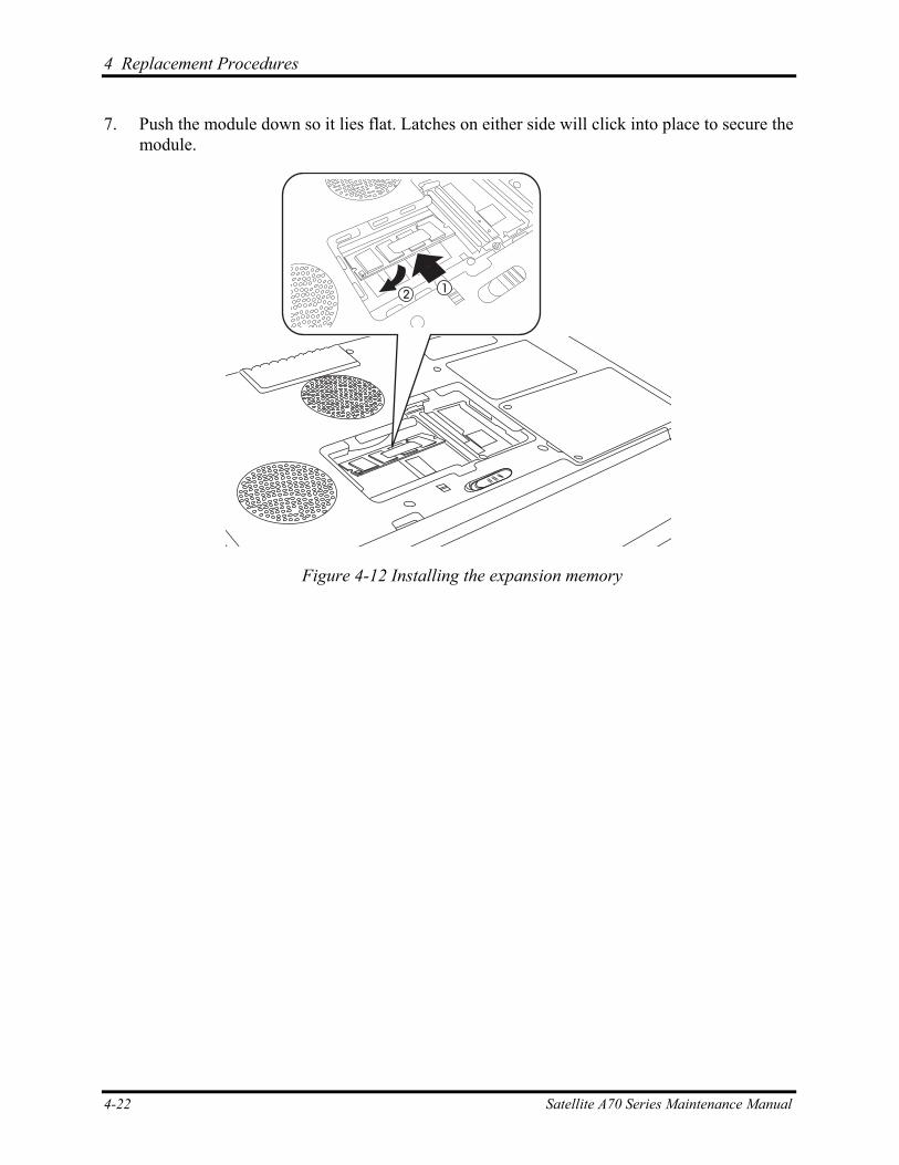
4 Replacement Procedures
7. Push the module down so it lies flat. Latches on either side will click into place to secure the module.
12
Figure 4-12 Installing the expansion memory
4-22 Satellite A70 Series Maintenance Manual
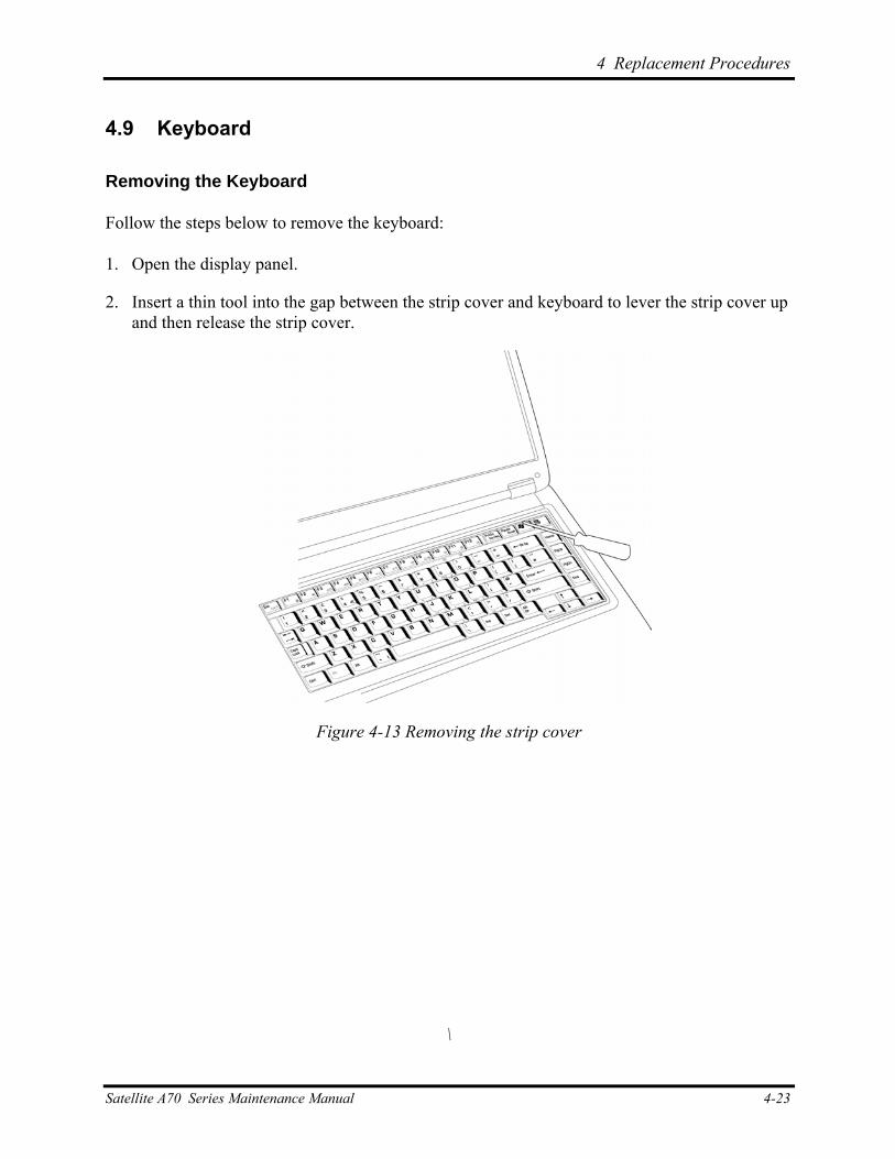
4 Replacement Procedures
4.9 Keyboard
Removing the Keyboard
Follow the steps below to remove the keyboard:
1. Open the display panel.
2. Insert a thin tool into the gap between the strip cover and keyboard to lever the strip cover up and then release the strip cover.
Figure 4-13 Removing the strip cover
\
Satellite A70 Series Maintenance Manual 4-23
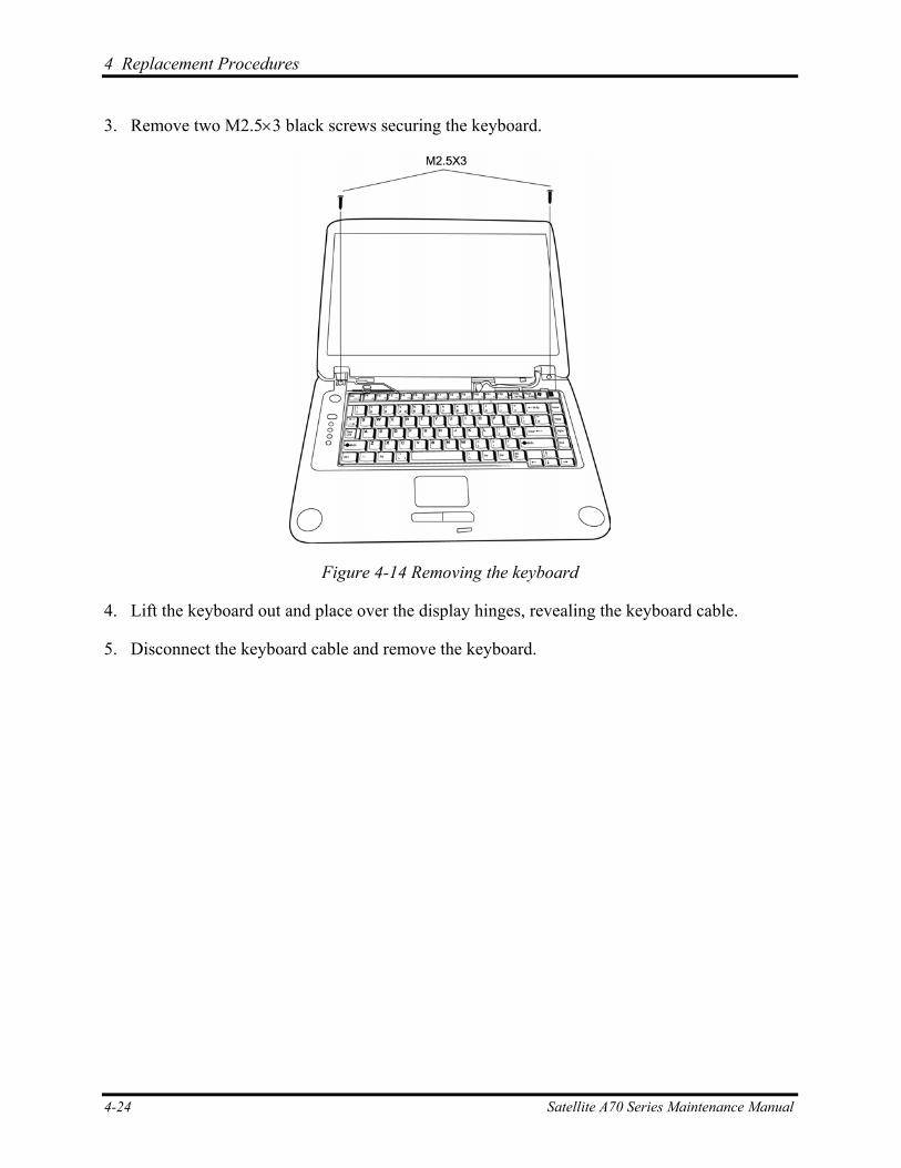
4 Replacement Procedures
3. Remove two M2.5×3 black screws securing the keyboard.
Figure 4-14 Removing the keyboard
4. Lift the keyboard out and place over the display hinges, revealing the keyboard cable.
5. Disconnect the keyboard cable and remove the keyboard.
4-24 Satellite A70 Series Maintenance Manual
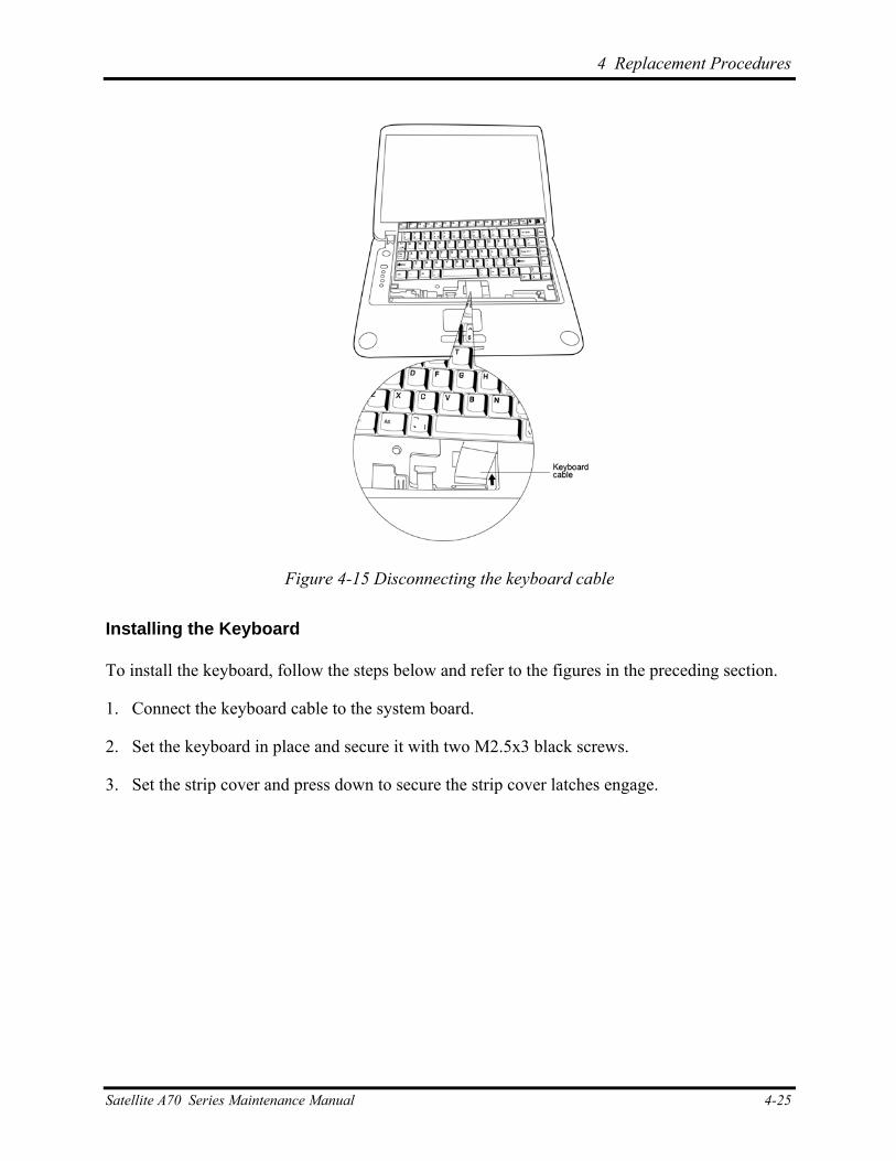
4 Replacement Procedures
Figure 4-15 Disconnecting the keyboard cable
Installing the Keyboard
To install the keyboard, follow the steps below and refer to the figures in the preceding section.
1. Connect the keyboard cable to the system board.
2. Set the keyboard in place and secure it with two M2.5x3 black screws.
3. Set the strip cover and press down to secure the strip cover latches engage.
Satellite A70 Series Maintenance Manual 4-25
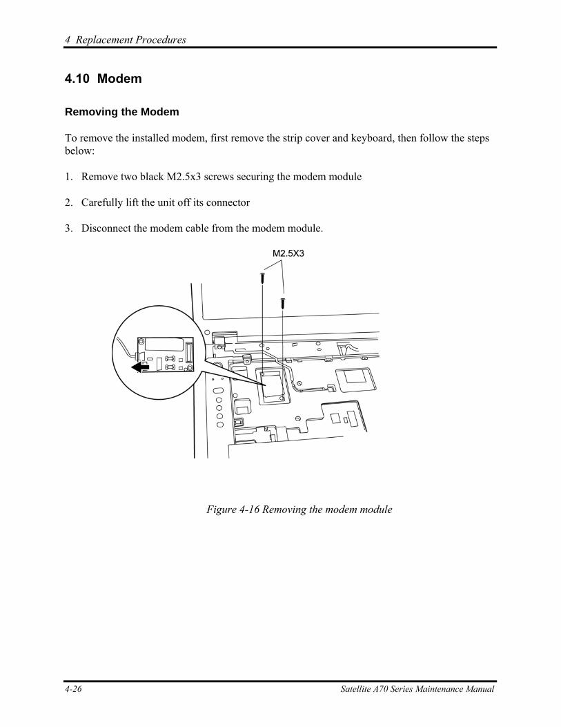
4 Replacement Procedures
4.10 Modem
Removing the Modem
To remove the installed modem, first remove the strip cover and keyboard, then follow the steps below:
1. Remove two black M2.5x3 screws securing the modem module
2. Carefully lift the unit off its connector
3. Disconnect the modem cable from the modem module.
Figure 4-16 Removing the modem module
4-26 Satellite A70 Series Maintenance Manual

4 Replacement Procedures
Installing the Modem
To install a modem, follow the steps below and refer to the figures in the preceding section.
1. Fit the modem onto its connector and secure it with two black M2.5x3 screws.
2. Connect the modem cable to the modem module.
3. Replace the keyboard and strip cover as mentioned in 4.9 Keyboard.
Satellite A70 Series Maintenance Manual 4-27
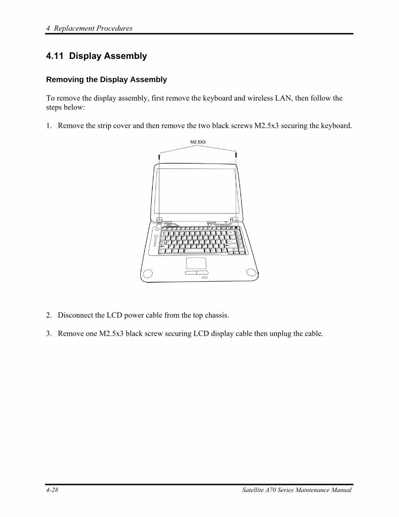
4 Replacement Procedures
4.11 Display Assembly
Removing the Display Assembly
To remove the display assembly, first remove the keyboard and wireless LAN, then follow the steps below:
1. Remove the strip cover and then remove the two black screws M2.5x3 securing the keyboard.
2. Disconnect the LCD power cable from the top chassis.
3. Remove one M2.5x3 black screw securing LCD display cable then unplug the cable.
4-28 Satellite A70 Series Maintenance Manual
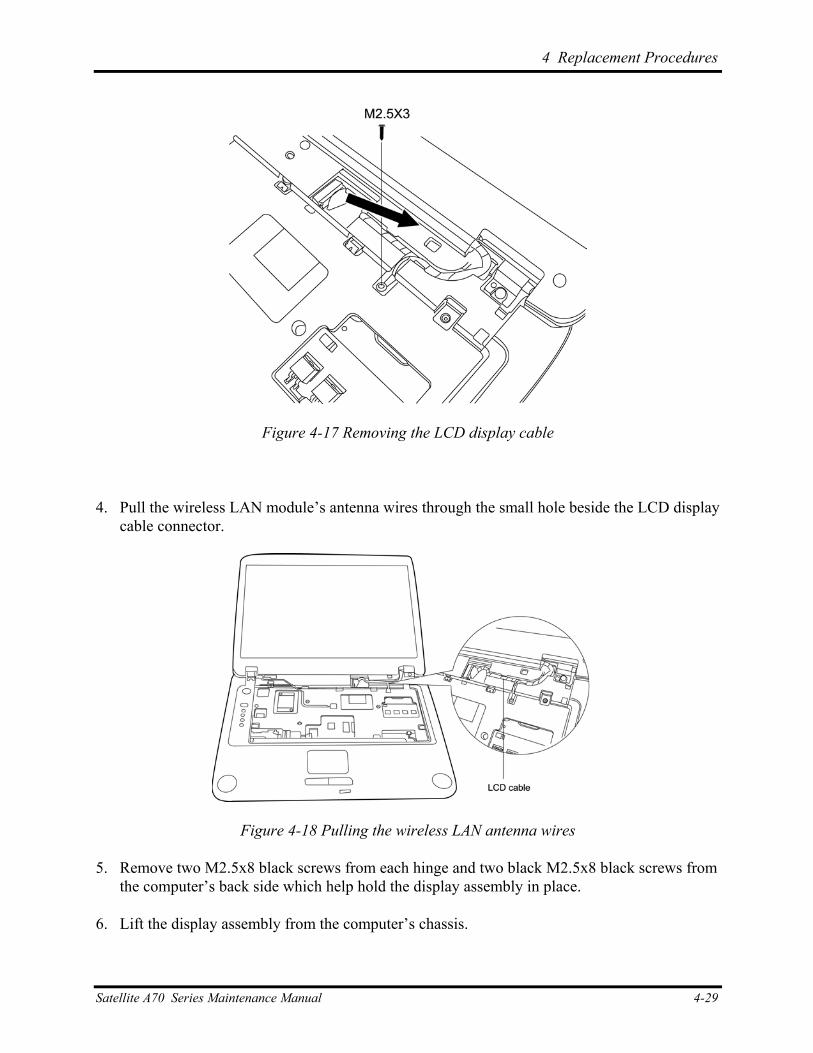
4 Replacement Procedures
Figure 4-17 Removing the LCD display cable
4. Pull the wireless LAN module’s antenna wires through the small hole beside the LCD display cable connector.
Figure 4-18 Pulling the wireless LAN antenna wires
5. Remove two M2.5x8 black screws from each hinge and two black M2.5x8 black screws from the computer’s back side which help hold the display assembly in place.
6. Lift the display assembly from the computer’s chassis.
Satellite A70 Series Maintenance Manual 4-29
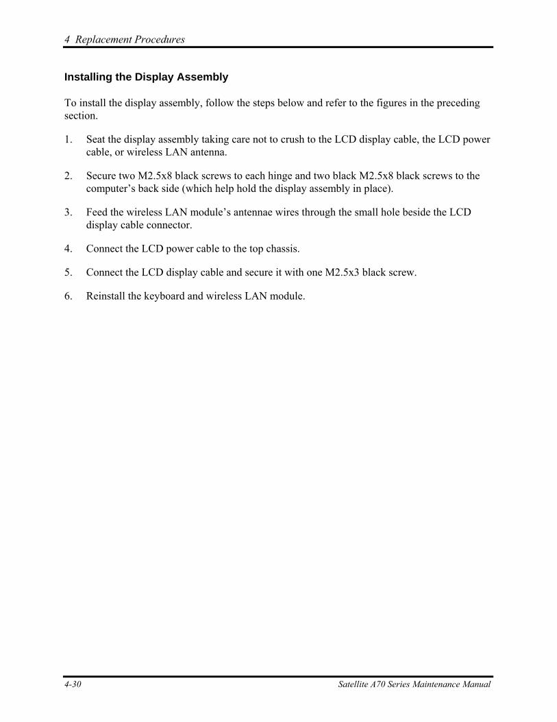
4 Replacement Procedures
Installing the Display Assembly
To install the display assembly, follow the steps below and refer to the figures in the preceding section.
1. Seat the display assembly taking care not to crush to the LCD display cable, the LCD power cable, or wireless LAN antenna.
2. Secure two M2.5x8 black screws to each hinge and two black M2.5x8 black screws to the computer’s back side (which help hold the display assembly in place).
3. Feed the wireless LAN module’s antennae wires through the small hole beside the LCD display cable connector.
4. Connect the LCD power cable to the top chassis.
5. Connect the LCD display cable and secure it with one M2.5x3 black screw.
6. Reinstall the keyboard and wireless LAN module.
4-30 Satellite A70 Series Maintenance Manual
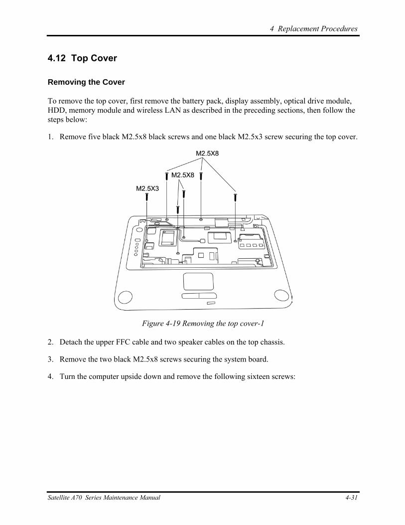
4 Replacement Procedures
4.12 Top Cover
Removing the Cover
To remove the top cover, first remove the battery pack, display assembly, optical drive module, HDD, memory module and wireless LAN as described in the preceding sections, then follow the steps below:
1. Remove five black M2.5x8 black screws and one black M2.5x3 screw securing the top cover.
Figure 4-19 Removing the top cover-1
2. Detach the upper FFC cable and two speaker cables on the top chassis.
3. Remove the two black M2.5x8 screws securing the system board.
4. Turn the computer upside down and remove the following sixteen screws:
Satellite A70 Series Maintenance Manual 4-31
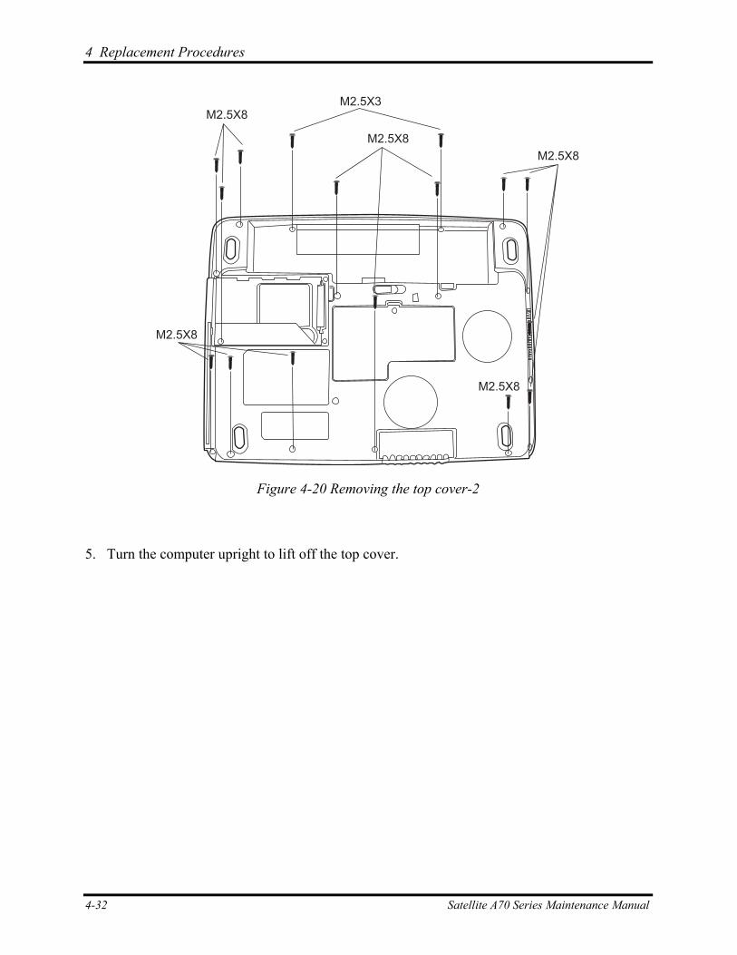
4 Replacement Procedures
M2.5X8
M2.5X8
M2.5X8
M2.5X8
M2.5X8
M2.5X3
Figure 4-20 Removing the top cover-2
5. Turn the computer upright to lift off the top cover.
4-32 Satellite A70 Series Maintenance Manual
4 Replacement Procedures
Installing the Top Cover
To install the top cover, follow the steps below and refer to the figures in the preceding section.
1. Seat the top cover and secure the upper FFC cable and two speaker cables to the computer’s top chassis.
2. Secure the top cover with five black M2.5x8 and one M2.5x3 black screws.
3. Turn the computer upside down and secure the sixteen screws.
Satellite A70 Series Maintenance Manual 4-33
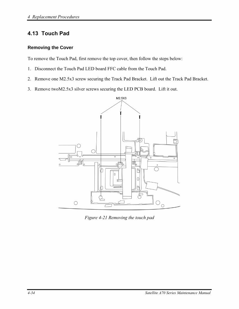
4 Replacement Procedures
4.13 Touch Pad
Removing the Cover
To remove the Touch Pad, first remove the top cover, then follow the steps below:
1. Disconnect the Touch Pad LED board FFC cable from the Touch Pad.
2. Remove one M2.5x3 screw securing the Track Pad Bracket. Lift out the Track Pad Bracket.
3. Remove twoM2.5x3 silver screws securing the LED PCB board. Lift it out.
Figure 4-21 Removing the touch pad
4-34 Satellite A70 Series Maintenance Manual
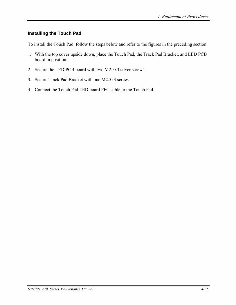
4 Replacement Procedures
Installing the Touch Pad
To install the Touch Pad, follow the steps below and refer to the figures in the preceding section:
1. With the top cover upside down, place the Touch Pad, the Track Pad Bracket, and LED PCB board in position.
2. Secure the LED PCB board with two M2.5x3 silver screws.
3. Secure Track Pad Bracket with one M2.5x3 screw.
4. Connect the Touch Pad LED board FFC cable to the Touch Pad.
Satellite A70 Series Maintenance Manual 4-35
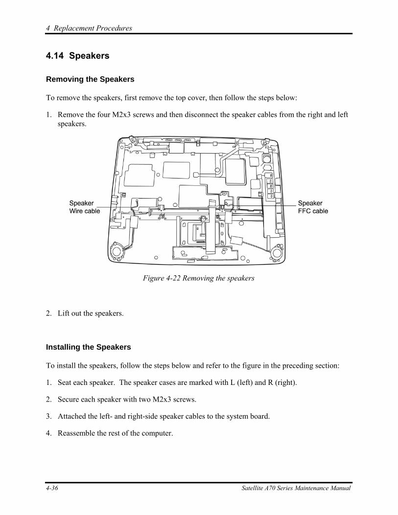
4 Replacement Procedures
4.14 Speakers
Removing the Speakers
To remove the speakers, first remove the top cover, then follow the steps below:
1. Remove the four M2x3 screws and then disconnect the speaker cables from the right and left speakers.
Figure 4-22 Removing the speakers
2. Lift out the speakers.
Installing the Speakers
To install the speakers, follow the steps below and refer to the figure in the preceding section:
1. Seat each speaker. The speaker cases are marked with L (left) and R (right).
2. Secure each speaker with two M2x3 screws.
3. Attached the left- and right-side speaker cables to the system board.
4. Reassemble the rest of the computer.
4-36 Satellite A70 Series Maintenance Manual
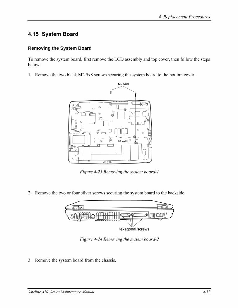
4 Replacement Procedures
4.15 System Board
Removing the System Board
To remove the system board, first remove the LCD assembly and top cover, then follow the steps below:
1. Remove the two black M2.5x8 screws securing the system board to the bottom cover.
Figure 4-23 Removing the system board-1
2. Remove the two or four silver screws securing the system board to the backside.
Figure 4-24 Removing the system board-2
3. Remove the system board from the chassis.
Satellite A70 Series Maintenance Manual 4-37
4 Replacement Procedures
Installing the System Board
To install the system board, follow the steps below and refer to the figures in the preceding section.
1. Seat the system board in the chassis and secure it with two black M2.5x8 screws.
2. Reassemble the computer.
4-38 Satellite A70 Series Maintenance Manual
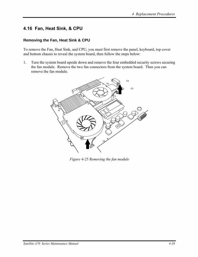
4 Replacement Procedures
4.16 Fan, Heat Sink, & CPU
Removing the Fan, Heat Sink & CPU
To remove the Fan, Heat Sink, and CPU, you must first remove the panel, keyboard, top cover and bottom chassis to reveal the system board, then follow the steps below:
1. Turn the system board upside down and remove the four embedded security screws securing the fan module. Remove the two fan connectors from the system board. Then you can remove the fan module.
Figure 4-25 Removing the fan module
Satellite A70 Series Maintenance Manual 4-39
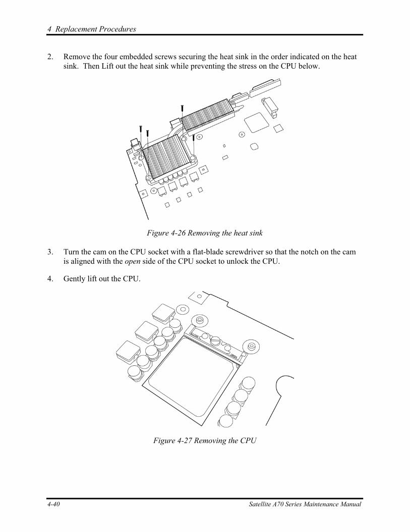
4 Replacement Procedures
2. Remove the four embedded screws securing the heat sink in the order indicated on the heat sink. Then Lift out the heat sink while preventing the stress on the CPU below.
Figure 4-26 Removing the heat sink
3. Turn the cam on the CPU socket with a flat-blade screwdriver so that the notch on the cam is aligned with the open side of the CPU socket to unlock the CPU.
4. Gently lift out the CPU.
Figure 4-27 Removing the CPU
4-40 Satellite A70 Series Maintenance Manual
4 Replacement Procedures
Installing the CPU
To install the CPU, follow the steps below and refer to the figures in the preceding section.
CAUTION: If you remove the heat sink, you should use the CPU grease tool to remove the grease on the CPU and heat sink. Reapply fresh grease before installing the heat sink.
1. Make sure that the notch on the cam is aligned with the open position.
2. Seat the CPU to align the triangle mark on the CPU with the one on the CPU socket. Make sure the alignment is exact to avoid damaging pins on the CPU.
3. Press the CPU softly with your fingers and turn the cam on the CPU socket to the closed position with a flat-blade screwdriver to secure the CPU.
4. Seat the heat sink over the CPU and secure with four screws in the order indicated on the heat sink.
5. Seat the fan module and secure with four embedded screws.
6. Attach the two fan connectors.
Satellite A70 Series Maintenance Manual 4-41
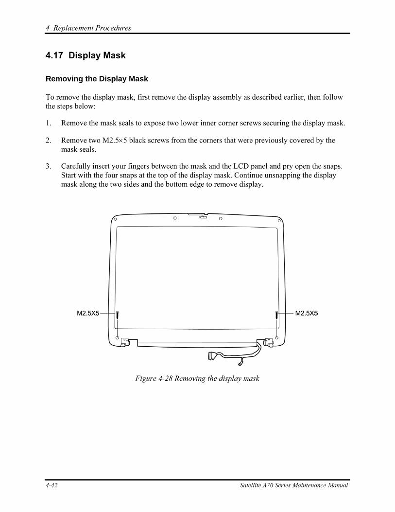
4 Replacement Procedures
4.17 Display Mask
Removing the Display Mask
To remove the display mask, first remove the display assembly as described earlier, then follow the steps below:
1. Remove the mask seals to expose two lower inner corner screws securing the display mask.
2. Remove two M2.5×5 black screws from the corners that were previously covered by the mask seals.
3. Carefully insert your fingers between the mask and the LCD panel and pry open the snaps. Start with the four snaps at the top of the display mask. Continue unsnapping the display mask along the two sides and the bottom edge to remove display.
Figure 4-28 Removing the display mask
4-42 Satellite A70 Series Maintenance Manual
4 Replacement Procedures
Installing the Display Mask
To install the display mask, follow the steps below and refer to the figures in the preceding section.
1. Seat the display mask and secure the snaps on each side.
2. Secure the display mask with two M2.5x5 screws at the bottom inner corner.
3. Cover the secured screws with mask seals.
Satellite A70 Series Maintenance Manual 4-43
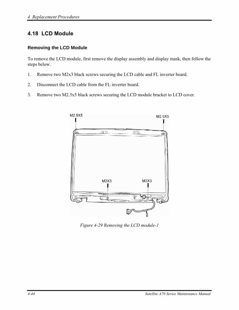
4 Replacement Procedures
4.18 LCD Module
Removing the LCD Module
To remove the LCD module, first remove the display assembly and display mask, then follow the steps below.
1. Remove two M2x3 black screws securing the LCD cable and FL inverter board.
2. Disconnect the LCD cable from the FL inverter board.
3. Remove two M2.5x5 black screws securing the LCD module bracket to LCD cover.
Figure 4-29 Removing the LCD module-1
4-44 Satellite A70 Series Maintenance Manual
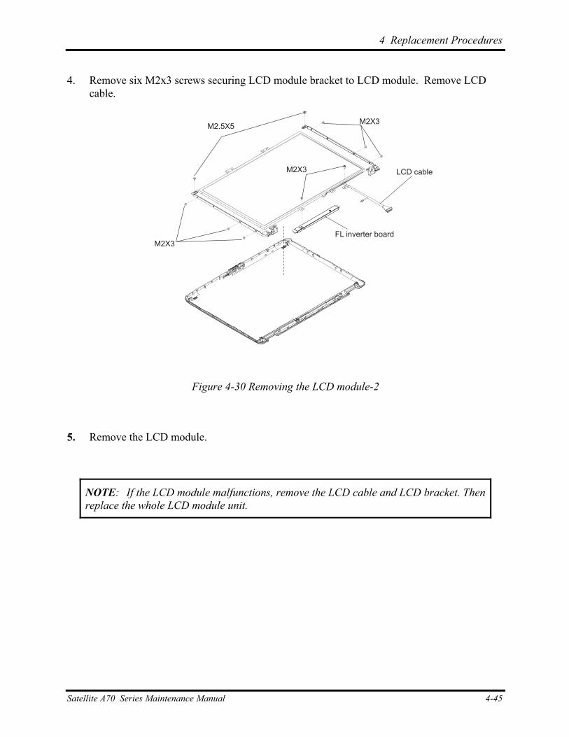
4 Replacement Procedures
4. Remove six M2x3 screws securing LCD module bracket to LCD module. Remove LCD cable.
LCD cable
M2X3
M2X3M2.5X5
M2X3
FL inverter board
Figure 4-30 Removing the LCD module-2
5. Remove the LCD module.
NOTE: If the LCD module malfunctions, remove the LCD cable and LCD bracket. Then replace the whole LCD module unit.
Satellite A70 Series Maintenance Manual 4-45
4 Replacement Procedures
Installing the LCD Module
To install the LCD module, follow the steps below and refer to the figures in the preceding section.
1. Set the LCD module in the display assembly.
2. Connect the FL cable and the HV cable to the FL inverter board.
3. Seat the LCD module in the display assembly with the LCD module bracket and six M2x3 black screws. Secure the LCD module with M2.5x5 black screws.
4. Secure two M2x3 black screws holding the left HV cable and FL inverter board in place.
4-46 Satellite A70 Series Maintenance Manual
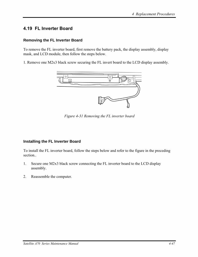
4 Replacement Procedures
Satellite A70 Series Maintenance Manual 4-47
4.19 FL Inverter Board
Removing the FL Inverter Board
To remove the FL inverter board, first remove the battery pack, the display assembly, display mask, and LCD module, then follow the steps below.
1. Remove one M2x3 black screw securing the FL invert board to the LCD display assembly.
Figure 4-31 Removing the FL inverter board
Installing the FL Inverter Board
To install the FL inverter board, follow the steps below and refer to the figure in the preceding section..
1. Secure one M2x3 black screw connecting the FL inverter board to the LCD display assembly.
2. Reassemble the computer.
Appendices
Appendices
App-ii Satellite P10 Series Maintenance Manual

Appendix Contents
Appendix A Handling the LCD Module............................................................................... A-1
Appendix B Board Layout..................................................................................................... B-1 B.1 System Board (FRDSY*) Bottom View......................................................................... B-1
B.2 System Board (FRDSY*) Top View .............................................................................. B-2
Appendix C Pin Assignments ................................................................................................ C-1 C.1 JP23/JP24 SODIMM I/F (200-PIN) ............................................................................... C-1
C.2 JP1/JP2 LCD I/F (22-pin) ............................................................................................... C-5
C.3 JP14 RGB I/F (15-pin).................................................................................................... C-6
C.4 JP10 HDD I/F (44-pin) ................................................................................................... C-7
C.5 JP28 ODD Module I/F (60-pin)...................................................................................... C-8
C.6 JP13 Parallel I/F (25-pin)................................................................................................ C-9
C.7 JP26 PC Card I/F (84-pin) ............................................................................................ C-10
C.8 JP19, JP22 Fan I/F (3-pin) ............................................................................................ C-14
C.9 PCN1 AC Adaptor Connector (3-pin) .......................................................................... C-14
C.10 JP29 LINE IN (6-pin) ................................................................................................... C-14
C.11 JP30 Microphone (6-pin) .............................................................................................. C-15
C.12 JP31 Headphone (6-pin) ............................................................................................... C-15
C.13 JP31 Headphone Connector (6-pin).............................................................................. C-15
C.14 JP29 LINE-IN Connector (6-pin) ................................................................................. C-15
Appendix D Keyboard Scan/Character Codes .................................................................... D-1
Appendix E Key Layout ........................................................................................................ E-1
E.1 United States (US) Keyboard...........................................................................................E-1
E.2 United Kingdom (UK) Keyboard ....................................................................................E-1
E.3 Spanish (SP) Keyboard ....................................................................................................E-2
E.4 Japanese (JA) Keyboard ..................................................................................................E-2
E.5 Korean (KO) Keyboard....................................................................................................E-3
E.6 Korean (CF) Keyboard ....................................................................................................E-3
E.7 Portuguese-ALPS Keyboard............................................................................................E-4
Satellite P10 Series Maintenance Manual App-iii

Appendix A
Appendix A Handling the LCD Module
Precautions for handling the LCD module
The LCD module can be easily damaged during assembly or disassembly. Therefore, please observe the following precautions when handling it:
1. When installing the LCD module in the LCD cover, be sure to seat it so that it is properly aligned and maximum visibility of the display is maintained.
2. Be careful to align the holes at the four corners of the LCD module with the corresponding holes in the LCD cover before securing the module with screws. Do not force the module into place, because stress can affect its performance.
Note: The panel’s polarized surface is easily scarred, so handle it carefully.
Satellite A70 Series Maintenance Manual A-1
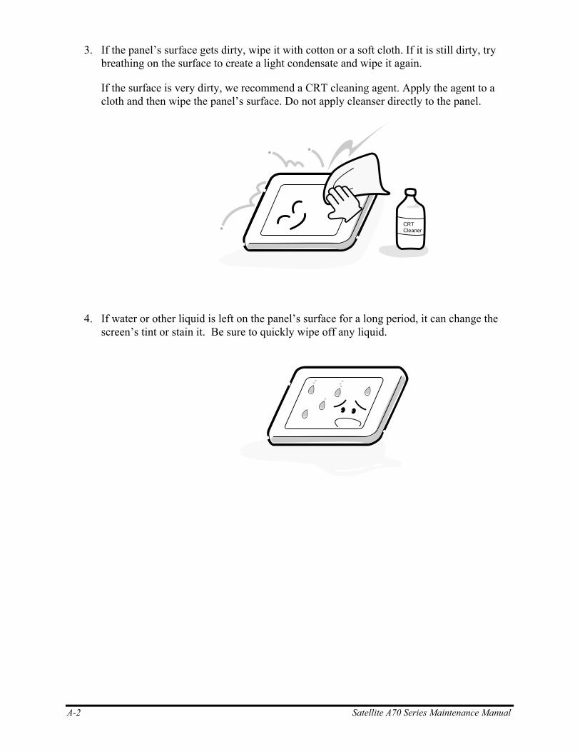
3. If the panel’s surface gets dirty, wipe it with cotton or a soft cloth. If it is still dirty, try breathing on the surface to create a light condensate and wipe it again.
If the surface is very dirty, we recommend a CRT cleaning agent. Apply the agent to a cloth and then wipe the panel’s surface. Do not apply cleanser directly to the panel.
CRTCleaner
4. If water or other liquid is left on the panel’s surface for a long period, it can change the screen’s tint or stain it. Be sure to quickly wipe off any liquid.
A-2 Satellite A70 Series Maintenance Manual

5. Glass is used in the panel, so be careful not to drop it or let it strike a hard object, which could cause breakage or cracks.
6. CMOS-LSI circuits are used in the module, so guard against damage from electrostatic discharge. Be sure to wear a wrist or ankle ground when handling the module.
Satellite A70 Series Maintenance Manual A-3
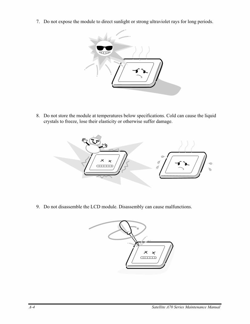
7. Do not expose the module to direct sunlight or strong ultraviolet rays for long periods.
8. Do not store the module at temperatures below specifications. Cold can cause the liquid crystals to freeze, lose their elasticity or otherwise suffer damage.
9. Do not disassemble the LCD module. Disassembly can cause malfunctions.
A-4 Satellite A70 Series Maintenance Manual
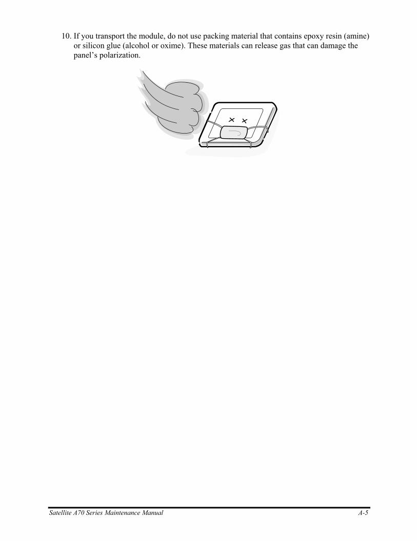
10. If you transport the module, do not use packing material that contains epoxy resin (amine) or silicon glue (alcohol or oxime). These materials can release gas that can damage the panel’s polarization.
Satellite A70 Series Maintenance Manual A-5

A-6 Satellite A70 Series Maintenance Manual
Appendices
E.8 US-INTE_ALPS Keyboard............................................................................................. E-4
E.9 Greece(GR) Keyboard..................................................................................................... E-5
E.10 France (FR) Keyboard..................................................................................................... E-5
E.11 Chinese (CH) Keyboard .................................................................................................. E-6
E.12 Swissc-Darfon Keyboard ................................................................................................ E-6
E.13 IT new Keyboard............................................................................................................. E-7
Appendix F Series Screw Torque List .................................................................................. F-1
Appendix G Reliability ...........................................................................................................G-1
App-iv Satellite P10 Series Maintenance Manual
Figures
Figure B-1 System board (FRDSY*) layout (Bottom) ......................................................... B-1
Figure B.2 System board (FRDSY*) layout (Top) ............................................................... B-2
Figure E-1 US keyboard.........................................................................................................E-1
Figure E-2 UK keyboard........................................................................................................E-1
Figure E-3 SP keyboard .........................................................................................................E-2
Figure E-4 JA keyboard .........................................................................................................E-2
Figure E-5 KO keyboard........................................................................................................E-3
Figure E-6 CF keyboard.........................................................................................................E-3
Figure E-7 Portuguese-ALPS keyboard.................................................................................E-4
Figure E-8 US-INTE_ALPS Keyboard .................................................................................E-4
Figure E-9 GR keyboard ........................................................................................................E-5
Figure E-10 FR keyboard.........................................................................................................E-5
Figure E-11 CH keyboard ........................................................................................................E-6
Figure E-12 Swissc-Darfon keyboard......................................................................................E-6
Figure E-13 IT new keyboard ..................................................................................................E-7
Satellite P10 Series Maintenance Manual App-v

Appendices
App-vi Satellite P10 Series Maintenance Manual
Tables
Table B-1 System board ICs (top and bottom).....................................................................B-3
Table B-2 System board connectors (top and bottom).........................................................B-4
Table C-1 SODIMM I/F pin assignments (200-PIN)...........................................................C-1
Table C-2 LCD I/F pin assignments (22-pin).......................................................................C-5
Table C-3 RGB I/F pin assignments (15-pin) ......................................................................C-6
Table C-4 HDD I/F pin assignments (44-pin)......................................................................C-7
Table C-5 ODD I/F pin assignments (50-pin)......................................................................C-8
Table C-6 Parallel I/F pin assignments (25-pin) ..................................................................C-9
Table C-7 PC Card I/F pin assignments (84-pin)...............................................................C-10
Table C-8 Mini PCI I/F pin assignments (124-pin)............................................................C-12
Table C-9-1 JP18 Fan I/F pin assignments (3-pin)................................................................C-14
Table C-9-2 JP21 Fan I/F pin assignments (3-pin)................................................................C-14
Table C-10 AC Adaptor Connector pin assignments (3-pin)...............................................C-14
Table C-11 Line in I/F pin assignments (6-pin) ..................................................................C-14
Table C-12 Microphone I/F pin assignments (6-pin) ...........................................................C-15
Table C-13 Microphone I/F pin assignments (6-pin) ...........................................................C-15
Table C-14 Headphone Connector pin assignments (6-pin) ................................................C-15
Table C-15 Headphone Connector pin assignments (6-pin) ................................................C-15
Table D-1 Scan codes (set 1 and set 2).................................................................................D-1
Table D-2 Scan codes with left Shift key .............................................................................D-5
Table D-3 Scan codes in Numlock mode .............................................................................D-6
Table D-4 Scan codes with Fn key .......................................................................................D-6
Table D-5 Scan codes in overlay mode ................................................................................D-7
Table D-6 No.124 key scan code..........................................................................................D-7
Table D-7 No.126 key scan code..........................................................................................D-8
Table F-1 Series Screw Torque List .................................................................................... F-1
Table G-1 MTBF ..................................................................................................................G-1
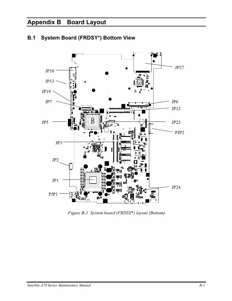
Appendix B
Appendix B Board Layout
B.1 System Board (FRDSY*) Bottom View
PJP1 JP24
JP23
JP19
JP13
JP12
JP10 JP27
JP7 JP6
JP5
JP3
JP2
JP1
PJP2
Figure B-1 System board (FRDSY*) layout (Bottom)
Satellite A70 Series Maintenance Manual B-1
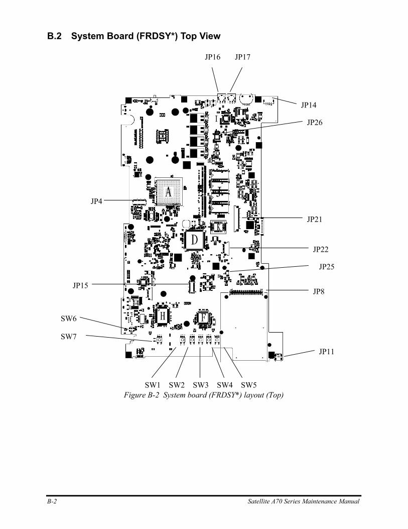
B.2 System Board (FRDSY*) Top View
JP16 JP17
JP26
JP25
JP22
JP21
JP15
JP14
JP11
JP8
JP4
SW6
SW7
Figure B-2 System board (FRDSY*) layout (Top) SW1 SW2 SW3 SW4 SW5
B-2 Satellite A70 Series Maintenance Manual

Table B-1 System board ICs (top and bottom)
Mark Number Name
A U51 ATI RC300ML
B U14 ATI IXP150
C U11 CLK GEN ICS951402AGT
D U39 KB/EC KB910Q
E U37 I/O Controller (LPC47N217-JN)
F U27 IEEE1394A_TSB43AB21A
G U21 Cardbus & 5-in-1 Card Reader ENE CB714
H U24 LAN controller RTL8100CL
I U32 AC97 CODEC ALC250
J U3,U4,U5,U6,U7,U8,U9,U10 On Board RAM
K U41 BIOS ROM512K8-90
Satellite A70 Series Maintenance Manual B-3
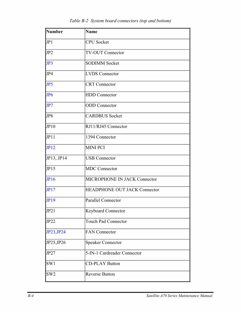
Table B-2 System board connectors (top and bottom)
Number Name
JP1 CPU Socket
JP2 TV-OUT Connector
JP3 SODIMM Socket
JP4 LVDS Connector
JP5 CRT Connector
JP6 HDD Connector
JP7 ODD Connector
JP8 CARDBUS Socket
JP10 RJ11/RJ45 Connector
JP11 1394 Connector
JP12 MINI PCI
JP13, JP14 USB Connector
JP15 MDC Connector
JP16 MICROPHONE IN JACK Connector
JP17 HEADPHONE OUT JACK Connector
JP19 Parallel Connector
JP21 Keyboard Connector
JP22 Touch Pad Connector
JP23,JP24 FAN Connector
JP25,JP26 Speaker Connector
JP27 5-IN-1 Cardreader Connector
SW1 CD-PLAY Button
SW2 Reverse Button
B-4 Satellite A70 Series Maintenance Manual
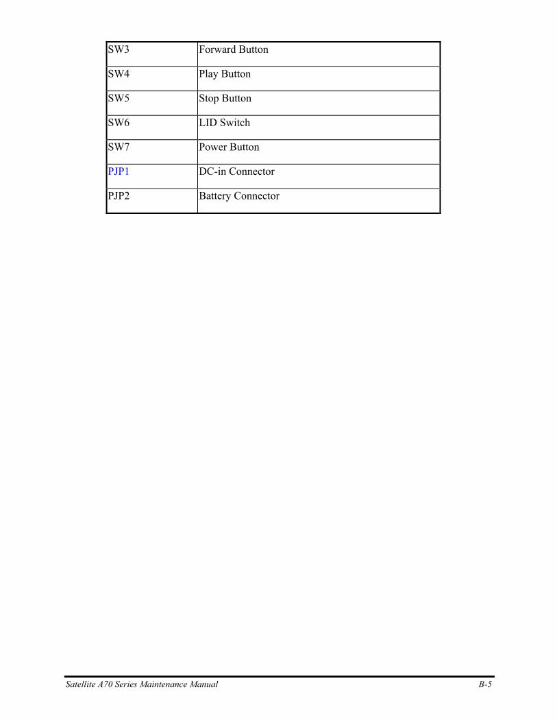
Satellite A70 Series Maintenance Manual B-5
SW3 Forward Button
SW4 Play Button
SW5 Stop Button
SW6 LID Switch
SW7 Power Button
PJP1 DC-in Connector
PJP2 Battery Connector
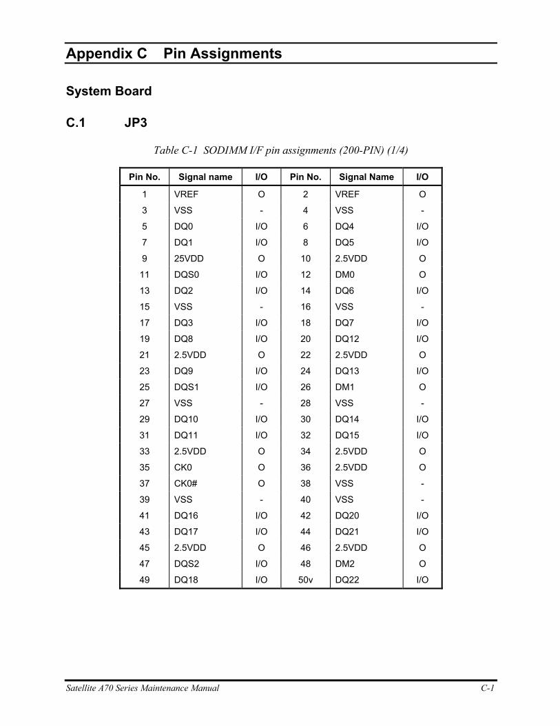
Satellite A70 Series Maintenance Manual C-1
C.
Appendix C Pin Assignments
System Board
C.1 JP3
Table C-1 SODIMM I/F pin assignments (200-PIN) (1/4)
Pin No. Signal name I/O Pin No. Signal Name I/O
1 VREF O 2 VREF O
3 VSS - 4 VSS -
5 DQ0 I/O 6 DQ4 I/O
7 DQ1 I/O 8 DQ5 I/O
9 25VDD O 10 2.5VDD O
11 DQS0 I/O 12 DM0 O
13 DQ2 I/O 14 DQ6 I/O
15 VSS - 16 VSS -
17 DQ3 I/O 18 DQ7 I/O
19 DQ8 I/O 20 DQ12 I/O
21 2.5VDD O 22 2.5VDD O
23 DQ9 I/O 24 DQ13 I/O
25 DQS1 I/O 26 DM1 O
27 VSS - 28 VSS -
29 DQ10 I/O 30 DQ14 I/O
31 DQ11 I/O 32 DQ15 I/O
33 2.5VDD O 34 2.5VDD O
35 CK0 O 36 2.5VDD O
37 CK0# O 38 VSS -
39 VSS - 40 VSS -
41 DQ16 I/O 42 DQ20 I/O
43 DQ17 I/O 44 DQ21 I/O
45 2.5VDD O 46 2.5VDD O
47 DQS2 I/O 48 DM2 O
49 DQ18 I/O 50v DQ22 I/O
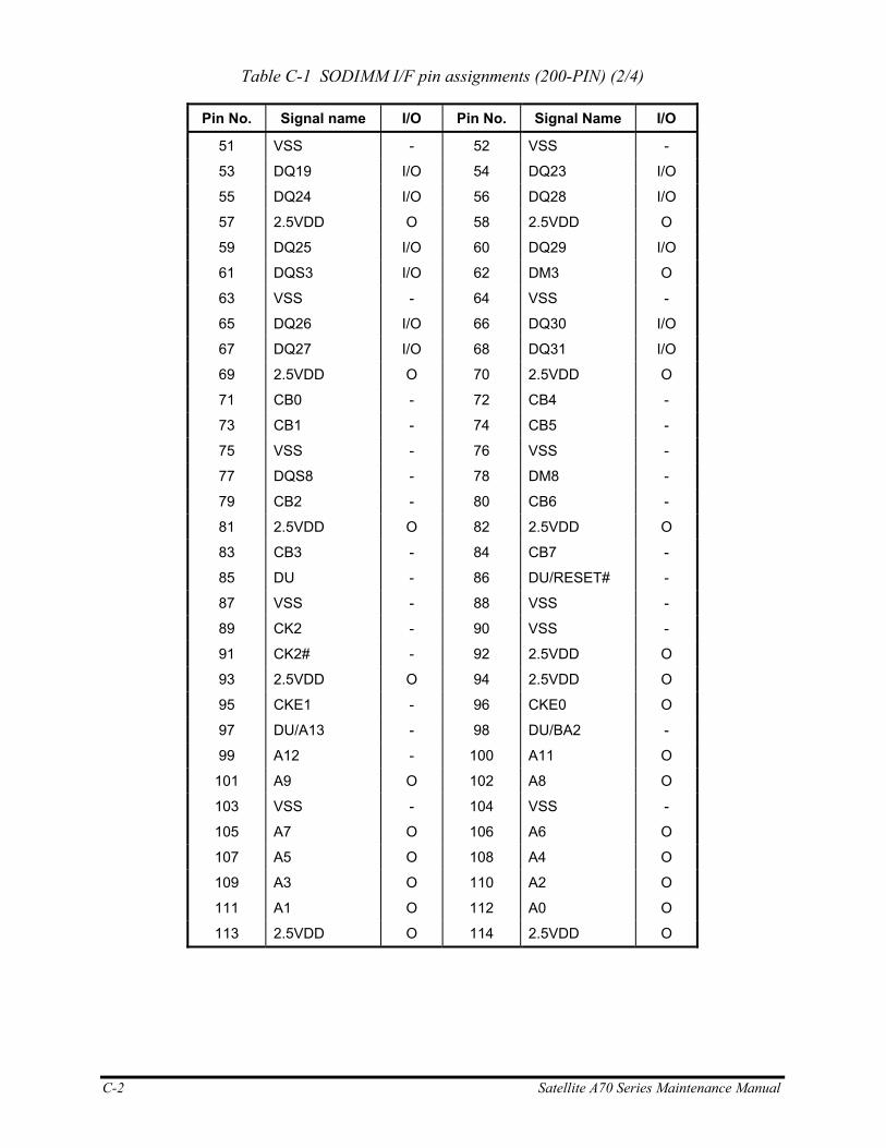
C-2 Satellite A70 Series Maintenance Manual
Table C-1 SODIMM I/F pin assignments (200-PIN) (2/4)
Pin No. Signal name I/O Pin No. Signal Name I/O
51 VSS - 52 VSS -
53 DQ19 I/O 54 DQ23 I/O
55 DQ24 I/O 56 DQ28 I/O
57 2.5VDD O 58 2.5VDD O
59 DQ25 I/O 60 DQ29 I/O
61 DQS3 I/O 62 DM3 O
63 VSS - 64 VSS -
65 DQ26 I/O 66 DQ30 I/O
67 DQ27 I/O 68 DQ31 I/O
69 2.5VDD O 70 2.5VDD O
71 CB0 - 72 CB4 -
73 CB1 - 74 CB5 -
75 VSS - 76 VSS -
77 DQS8 - 78 DM8 -
79 CB2 - 80 CB6 -
81 2.5VDD O 82 2.5VDD O
83 CB3 - 84 CB7 -
85 DU - 86 DU/RESET# -
87 VSS - 88 VSS -
89 CK2 - 90 VSS -
91 CK2# - 92 2.5VDD O
93 2.5VDD O 94 2.5VDD O
95 CKE1 - 96 CKE0 O
97 DU/A13 - 98 DU/BA2 -
99 A12 - 100 A11 O
101 A9 O 102 A8 O
103 VSS - 104 VSS -
105 A7 O 106 A6 O
107 A5 O 108 A4 O
109 A3 O 110 A2 O
111 A1 O 112 A0 O
113 2.5VDD O 114 2.5VDD O

Satellite A70 Series Maintenance Manual C-3
Table C-1 SODIMM I/F pin assignments (200-PIN) (3/4)
Pin No. Signal name I/O Pin No. Signal Name I/O
115 A10/AP O 116 BA1 O
117 BA0 O 118 RAS# O
119 WE# O 120 CAS# O
121 SO# O 122 S1# -
123 DU - 124 DU -
125 VSS - 126 VSS -
127 DQ32 I/O 128 DQ36 I/O
129 DQ33 I/O 130 DQ37 I/O
131 2.5VDD O 132 2.5VDD O
133 DQS4 I/O 134 DM4 O
135 DQ34 I/O 136 DQ38 I/O
137 VSS - 138 VSS -
139 DQ35 I/O 140 DQ39 I/O
141 DQ40 I/O 142 DQ44 I/O
143 2.5VDD O 144 2.5VDD O
145 DQ41 I/O 146 DQ45 I/O
147 DQS5 I/O 148 DM5 O
149 VSS - 150 VSS -
151 DQ42 I/O 152 DQ46 I/O
153 DQ43 I/O 154 DQ47 I/O
155 2.5VDD O 156 2.5VDD O
157 2.5VDD O 158 CK1# O
159 VSS - 160 CK1 O
161 VSS - 162 VSS -
163 DQ48 I/O 164 DQ52 I/O
165 DQ49 I/O 166 DQ53 I/O
167 2.5VDD O 168 2.5VDD O
169 DQS6 I/O 170 DM6 O
171 DQ50 I/O 172 DQ54 I/O
173 VSS - 174 VSS -
175 DQ51 I/O 176 DQ55 I/O
177 DQ56 I/O 178 DQ60 I/O
179 2.5VDD O 180 2.5VDD O
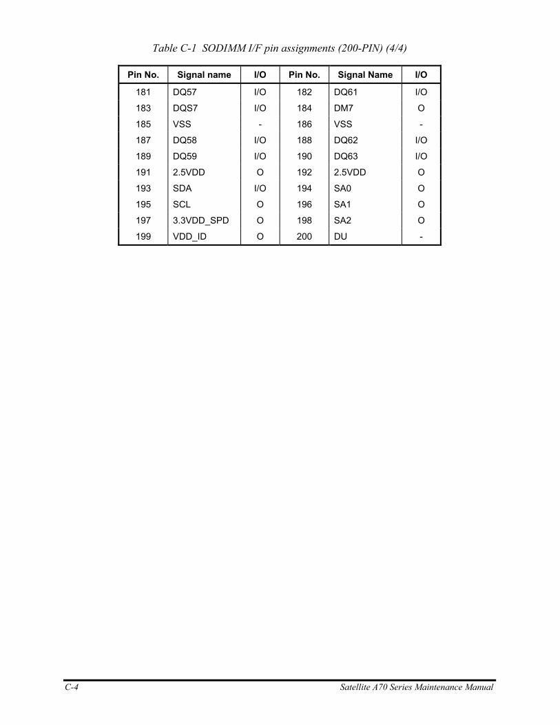
C-4 Satellite A70 Series Maintenance Manual
Table C-1 SODIMM I/F pin assignments (200-PIN) (4/4)
Pin No. Signal name I/O Pin No. Signal Name I/O
181 DQ57 I/O 182 DQ61 I/O
183 DQS7 I/O 184 DM7 O
185 VSS - 186 VSS -
187 DQ58 I/O 188 DQ62 I/O
189 DQ59 I/O 190 DQ63 I/O
191 2.5VDD O 192 2.5VDD O
193 SDA I/O 194 SA0 O
195 SCL O 196 SA1 O
197 3.3VDD_SPD O 198 SA2 O
199 VDD_ID O 200 DU -
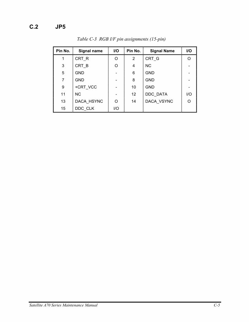
Satellite A70 Series Maintenance Manual C-5
C.2 JP5
Table C-3 RGB I/F pin assignments (15-pin)
Pin No. Signal name I/O Pin No. Signal Name I/O
1 CRT_R O 2 CRT_G O
3 CRT_B O 4 NC -
5 GND - 6 GND -
7 GND - 8 GND -
9 +CRT_VCC - 10 GND -
11 NC - 12 DDC_DATA I/O
13 DACA_HSYNC O 14 DACA_VSYNC O
15 DDC_CLK I/O
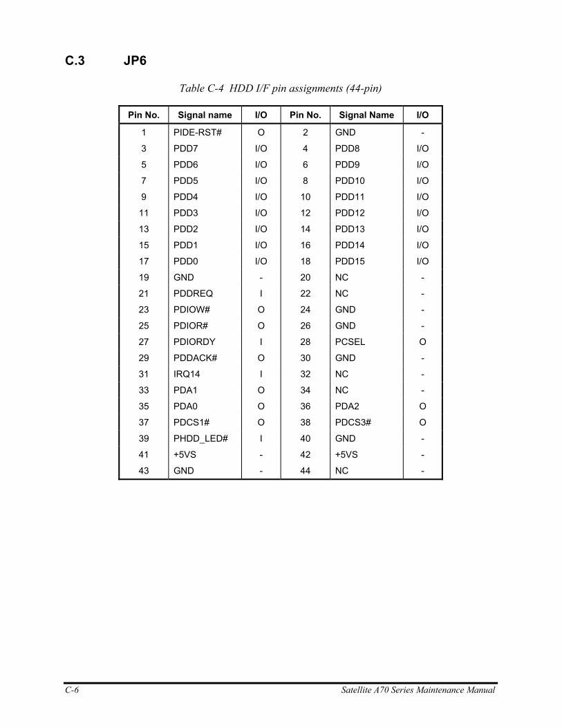
C-6 Satellite A70 Series Maintenance Manual
C.3 JP6
Table C-4 HDD I/F pin assignments (44-pin)
Pin No. Signal name I/O Pin No. Signal Name I/O
1 PIDE-RST# O 2 GND -
3 PDD7 I/O 4 PDD8 I/O
5 PDD6 I/O 6 PDD9 I/O
7 PDD5 I/O 8 PDD10 I/O
9 PDD4 I/O 10 PDD11 I/O
11 PDD3 I/O 12 PDD12 I/O
13 PDD2 I/O 14 PDD13 I/O
15 PDD1 I/O 16 PDD14 I/O
17 PDD0 I/O 18 PDD15 I/O
19 GND - 20 NC -
21 PDDREQ I 22 NC -
23 PDIOW# O 24 GND -
25 PDIOR# O 26 GND -
27 PDIORDY I 28 PCSEL O
29 PDDACK# O 30 GND -
31 IRQ14 I 32 NC -
33 PDA1 O 34 NC -
35 PDA0 O 36 PDA2 O
37 PDCS1# O 38 PDCS3# O
39 PHDD_LED# I 40 GND -
41 +5VS - 42 +5VS -
43 GND - 44 NC -
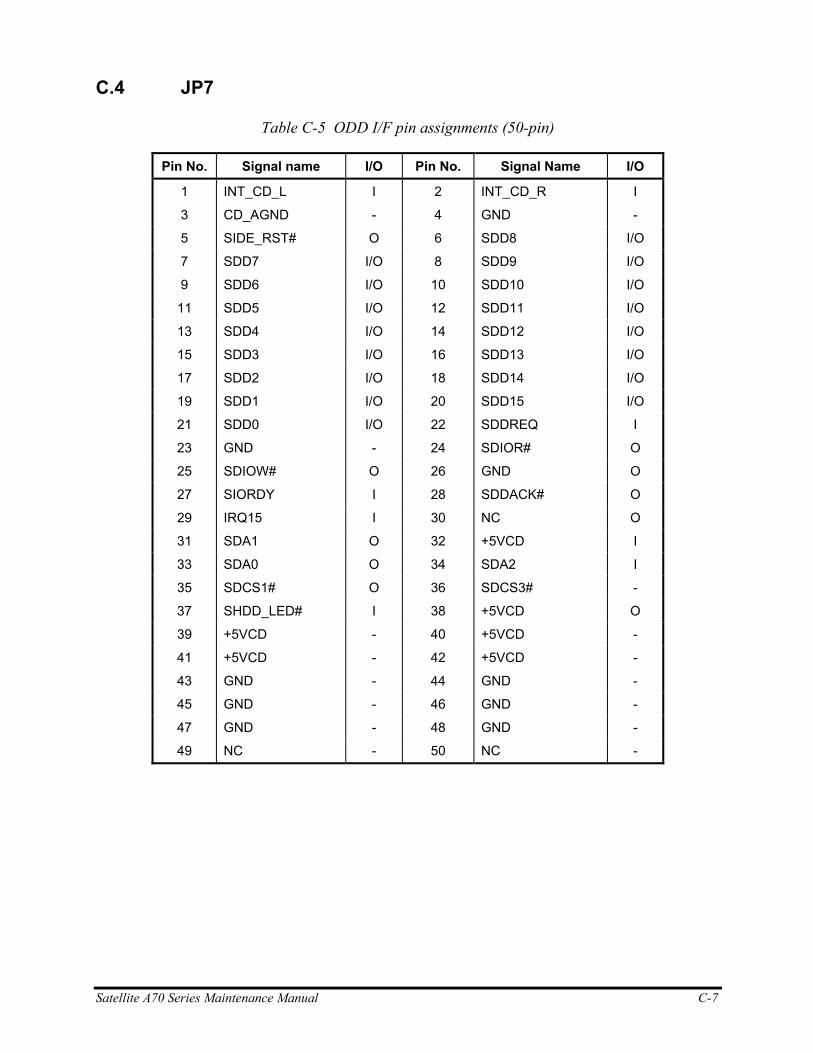
Satellite A70 Series Maintenance Manual C-7
C.4 JP7
Table C-5 ODD I/F pin assignments (50-pin)
Pin No. Signal name I/O Pin No. Signal Name I/O
1 INT_CD_L I 2 INT_CD_R I
3 CD_AGND - 4 GND -
5 SIDE_RST# O 6 SDD8 I/O
7 SDD7 I/O 8 SDD9 I/O
9 SDD6 I/O 10 SDD10 I/O
11 SDD5 I/O 12 SDD11 I/O
13 SDD4 I/O 14 SDD12 I/O
15 SDD3 I/O 16 SDD13 I/O
17 SDD2 I/O 18 SDD14 I/O
19 SDD1 I/O 20 SDD15 I/O
21 SDD0 I/O 22 SDDREQ I
23 GND - 24 SDIOR# O
25 SDIOW# O 26 GND O
27 SIORDY I 28 SDDACK# O
29 IRQ15 I 30 NC O
31 SDA1 O 32 +5VCD I
33 SDA0 O 34 SDA2 I
35 SDCS1# O 36 SDCS3# -
37 SHDD_LED# I 38 +5VCD O
39 +5VCD - 40 +5VCD -
41 +5VCD - 42 +5VCD -
43 GND - 44 GND -
45 GND - 46 GND -
47 GND - 48 GND -
49 NC - 50 NC -
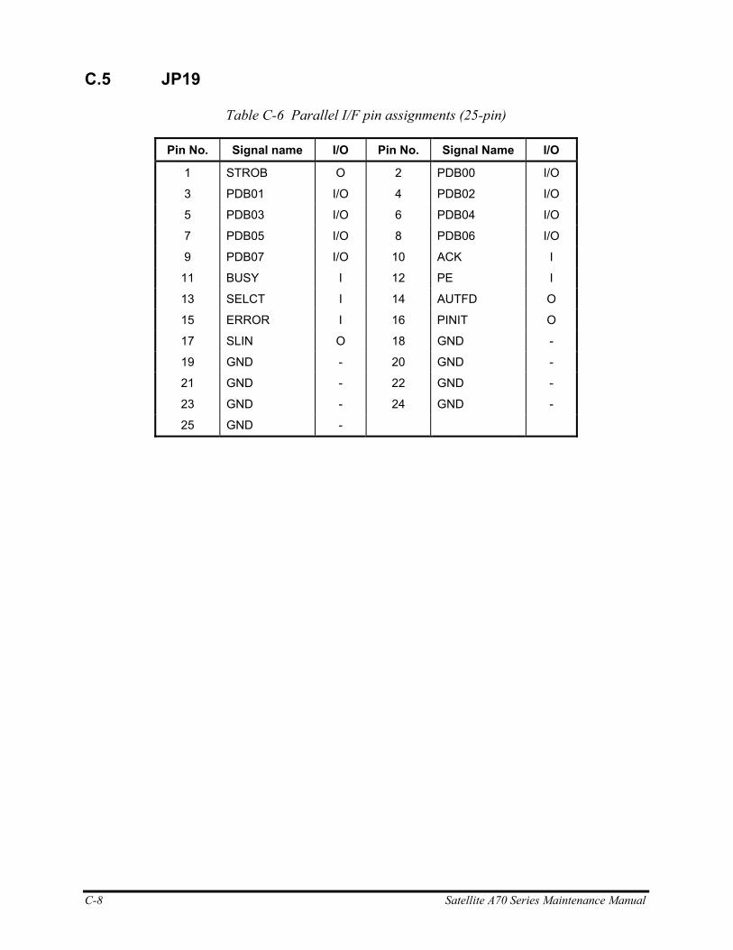
C-8 Satellite A70 Series Maintenance Manual
C.5 JP19
Table C-6 Parallel I/F pin assignments (25-pin)
Pin No. Signal name I/O Pin No. Signal Name I/O
1 STROB O 2 PDB00 I/O
3 PDB01 I/O 4 PDB02 I/O
5 PDB03 I/O 6 PDB04 I/O
7 PDB05 I/O 8 PDB06 I/O
9 PDB07 I/O 10 ACK I
11 BUSY I 12 PE I
13 SELCT I 14 AUTFD O
15 ERROR I 16 PINIT O
17 SLIN O 18 GND -
19 GND - 20 GND -
21 GND - 22 GND -
23 GND - 24 GND -
25 GND -
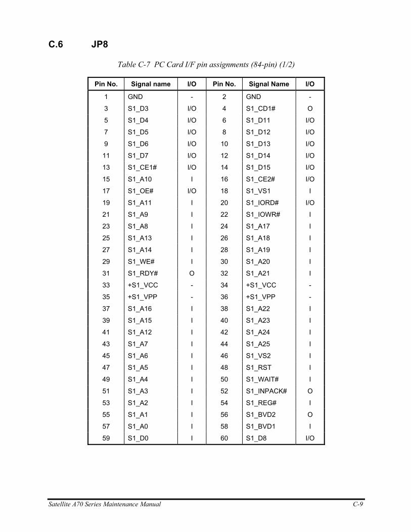
Satellite A70 Series Maintenance Manual C-9
C.6 JP8
Table C-7 PC Card I/F pin assignments (84-pin) (1/2)
Pin No. Signal name I/O Pin No. Signal Name I/O
1 GND - 2 GND -
3 S1_D3 I/O 4 S1_CD1# O
5 S1_D4 I/O 6 S1_D11 I/O
7 S1_D5 I/O 8 S1_D12 I/O
9 S1_D6 I/O 10 S1_D13 I/O
11 S1_D7 I/O 12 S1_D14 I/O
13 S1_CE1# I/O 14 S1_D15 I/O
15 S1_A10 I 16 S1_CE2# I/O
17 S1_OE# I/O 18 S1_VS1 I
19 S1_A11 I 20 S1_IORD# I/O
21 S1_A9 I 22 S1_IOWR# I
23 S1_A8 I 24 S1_A17 I
25 S1_A13 I 26 S1_A18 I
27 S1_A14 I 28 S1_A19 I
29 S1_WE# I 30 S1_A20 I
31 S1_RDY# O 32 S1_A21 I
33 +S1_VCC - 34 +S1_VCC -
35 +S1_VPP - 36 +S1_VPP -
37 S1_A16 I 38 S1_A22 I
39 S1_A15 I 40 S1_A23 I
41 S1_A12 I 42 S1_A24 I
43 S1_A7 I 44 S1_A25 I
45 S1_A6 I 46 S1_VS2 I
47 S1_A5 I 48 S1_RST I
49 S1_A4 I 50 S1_WAIT# I
51 S1_A3 I 52 S1_INPACK# O
53 S1_A2 I 54 S1_REG# I
55 S1_A1 I 56 S1_BVD2 O
57 S1_A0 I 58 S1_BVD1 I
59 S1_D0 I 60 S1_D8 I/O
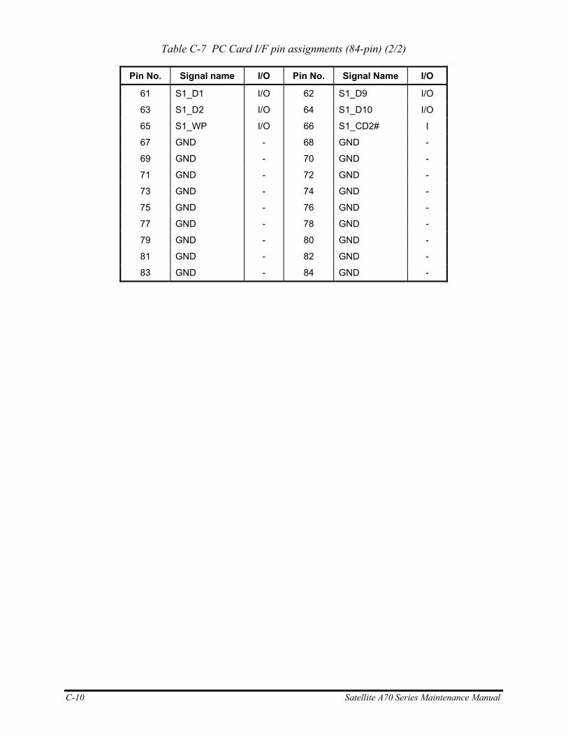
C-10 Satellite A70 Series Maintenance Manual
Table C-7 PC Card I/F pin assignments (84-pin) (2/2)
Pin No. Signal name I/O Pin No. Signal Name I/O
61 S1_D1 I/O 62 S1_D9 I/O
63 S1_D2 I/O 64 S1_D10 I/O
65 S1_WP I/O 66 S1_CD2# I
67 GND - 68 GND -
69 GND - 70 GND -
71 GND - 72 GND -
73 GND - 74 GND -
75 GND - 76 GND -
77 GND - 78 GND -
79 GND - 80 GND -
81 GND - 82 GND -
83 GND - 84 GND -
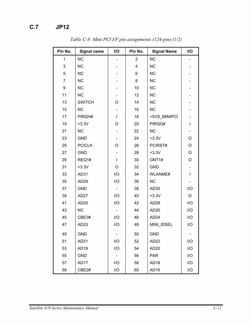
Satellite A70 Series Maintenance Manual C-11
C.7 JP12
Table C-8 Mini PCI I/F pin assignments (124-pin) (1/2)
Pin No. Signal name I/O Pin No. Signal Name I/O
1 NC - 2 NC -
3 NC - 4 NC -
5 NC - 6 NC -
7 NC - 8 NC -
9 NC - 10 NC -
11 NC - 12 NC -
13 SWITCH O 14 NC -
15 NC - 16 NC -
17 PIRQH# I 18 +5VS_MINIPCI -
19 +3.3V O 20 PIRQG# I
21 NC - 22 NC -
23 GND - 24 +3.3V O
25 PCICLK O 26 PCIRST# O
27 GND - 28 +3.3V O
29 REQ1# I 30 GNT1# O
31 +3.3V O 32 GND -
33 AD31 I/O 34 WLANME# I
35 AD29 I/O 36 NC -
37 GND - 38 AD30 I/O
39 AD27 I/O 40 +3.3V O
41 AD25 I/O 42 AD28 I/O
43 NC - 44 AD26 I/O
45 CBE3# I/O 46 AD24 I/O
47 AD23 I/O 48 MINI_IDSEL I/O
49 GND - 50 GND -
51 AD21 I/O 52 AD22 I/O
53 AD19 I/O 54 AD20 I/O
55 GND - 56 PAR I/O
57 AD17 I/O 58 AD18 I/O
59 CBE2# I/O 60 AD16 I/O
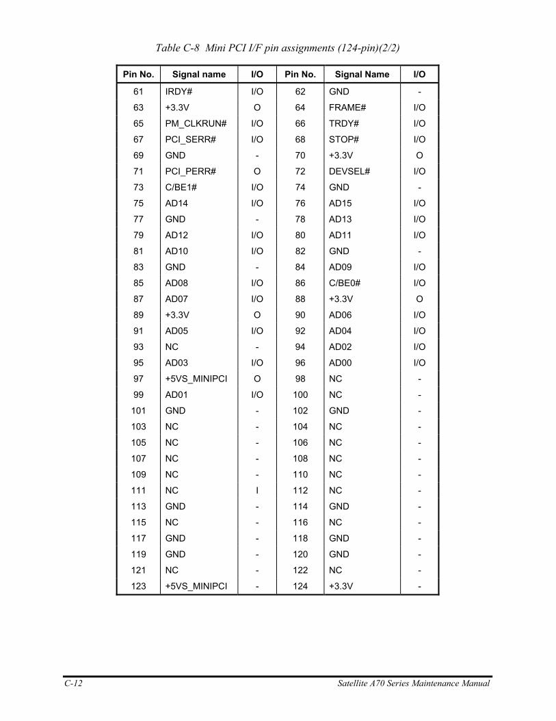
C-12 Satellite A70 Series Maintenance Manual
Table C-8 Mini PCI I/F pin assignments (124-pin)(2/2)
Pin No. Signal name I/O Pin No. Signal Name I/O
61 IRDY# I/O 62 GND -
63 +3.3V O 64 FRAME# I/O
65 PM_CLKRUN# I/O 66 TRDY# I/O
67 PCI_SERR# I/O 68 STOP# I/O
69 GND - 70 +3.3V O
71 PCI_PERR# O 72 DEVSEL# I/O
73 C/BE1# I/O 74 GND -
75 AD14 I/O 76 AD15 I/O
77 GND - 78 AD13 I/O
79 AD12 I/O 80 AD11 I/O
81 AD10 I/O 82 GND -
83 GND - 84 AD09 I/O
85 AD08 I/O 86 C/BE0# I/O
87 AD07 I/O 88 +3.3V O
89 +3.3V O 90 AD06 I/O
91 AD05 I/O 92 AD04 I/O
93 NC - 94 AD02 I/O
95 AD03 I/O 96 AD00 I/O
97 +5VS_MINIPCI O 98 NC -
99 AD01 I/O 100 NC -
101 GND - 102 GND -
103 NC - 104 NC -
105 NC - 106 NC -
107 NC - 108 NC -
109 NC - 110 NC -
111 NC I 112 NC -
113 GND - 114 GND -
115 NC - 116 NC -
117 GND - 118 GND -
119 GND - 120 GND -
121 NC - 122 NC -
123 +5VS_MINIPCI - 124 +3.3V -
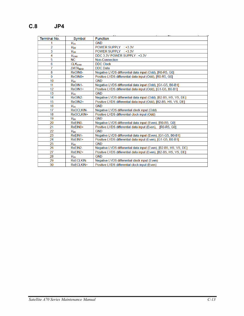
Satellite A70 Series Maintenance Manual C-13
C.8 JP4
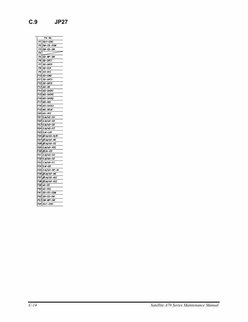
C-14 Satellite A70 Series Maintenance Manual
C.9 JP27
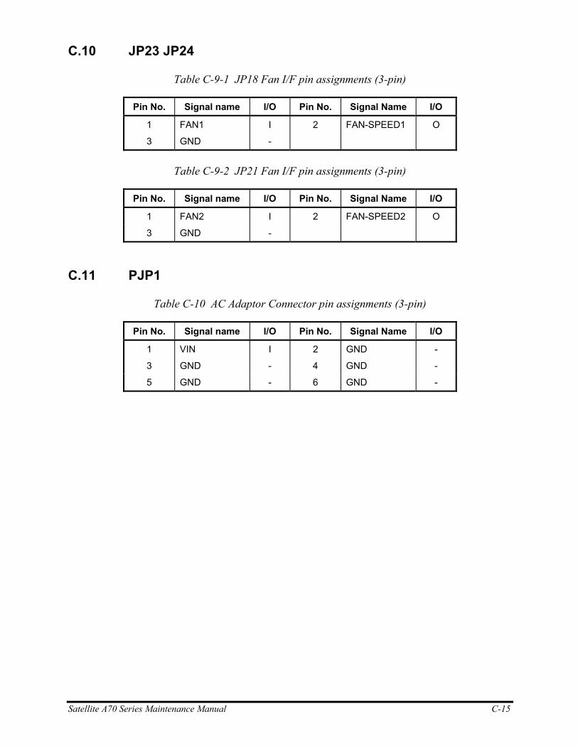
Satellite A70 Series Maintenance Manual C-15
C.10 JP23 JP24
Table C-9-1 JP18 Fan I/F pin assignments (3-pin)
Pin No. Signal name I/O Pin No. Signal Name I/O
1 FAN1 I 2 FAN-SPEED1 O
3 GND -
Table C-9-2 JP21 Fan I/F pin assignments (3-pin)
Pin No. Signal name I/O Pin No. Signal Name I/O
1 FAN2 I 2 FAN-SPEED2 O
3 GND -
C.11 PJP1
Table C-10 AC Adaptor Connector pin assignments (3-pin)
Pin No. Signal name I/O Pin No. Signal Name I/O
1 VIN I 2 GND -
3 GND - 4 GND -
5 GND - 6 GND -

C-16 Satellite A70 Series Maintenance Manual
C.12 JP16
Table C-12 Microphone I/F pin assignments (6-pin)
Pin No. Signal name I/O Pin No. Signal Name I/O
1 ANGND - 2 MIC I
3 BIAS I 4 NC -
5 NC - 6 ANGND -
C.13 JP17
Table C-14 Headphone Connector pin assignments (6-pin)
Pin No. Signal name I/O Pin No. Signal Name I/O
1 ANGND - 2 INTSPK_L1 O
3 INTSPK_R1 O 4 NBA_PLUG I
5 ANGND - 6 NC -
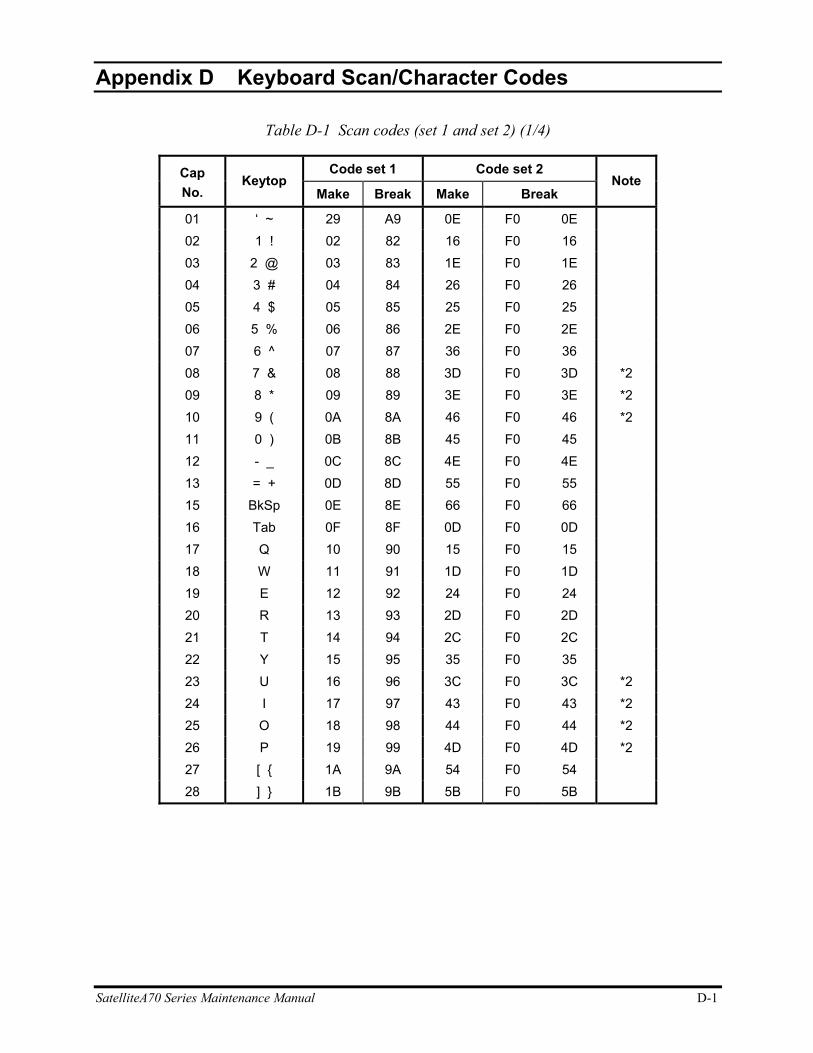
SatelliteA70 Series Maintenance Manual D-1
Appendix D
Appendix D Keyboard Scan/Character Codes
Table D-1 Scan codes (set 1 and set 2) (1/4)
Code set 1 Code set 2 Cap No.
Keytop Make Break Make Break
Note
01 ‘ ~ 29 A9 0E F0 0E 02 1 ! 02 82 16 F0 16 03 2 @ 03 83 1E F0 1E 04 3 # 04 84 26 F0 26 05 4 $ 05 85 25 F0 25 06 5 % 06 86 2E F0 2E 07 6 ^ 07 87 36 F0 36 08 7 & 08 88 3D F0 3D *2 09 8 * 09 89 3E F0 3E *2 10 9 ( 0A 8A 46 F0 46 *2 11 0 ) 0B 8B 45 F0 45 12 - _ 0C 8C 4E F0 4E 13 = + 0D 8D 55 F0 55 15 BkSp 0E 8E 66 F0 66 16 Tab 0F 8F 0D F0 0D 17 Q 10 90 15 F0 15 18 W 11 91 1D F0 1D 19 E 12 92 24 F0 24 20 R 13 93 2D F0 2D 21 T 14 94 2C F0 2C 22 Y 15 95 35 F0 35 23 U 16 96 3C F0 3C *2 24 I 17 97 43 F0 43 *2 25 O 18 98 44 F0 44 *2 26 P 19 99 4D F0 4D *2 27 [ { 1A 9A 54 F0 54 28 ] } 1B 9B 5B F0 5B
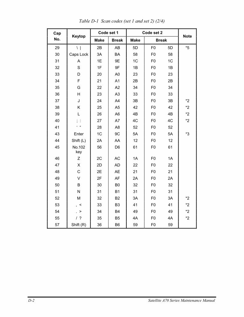
D-2 Satellite A70 Series Maintenance Manual
Table D-1 Scan codes (set 1 and set 2) (2/4)
Code set 1 Code set 2 Cap No.
Keytop Make Break Make Break
Note
29 \ | 2B AB 5D F0 5D *5 30 Caps Lock 3A BA 58 F0 58 31 A 1E 9E 1C F0 1C 32 S 1F 9F 1B F0 1B 33 D 20 A0 23 F0 23 34 F 21 A1 2B F0 2B 35 G 22 A2 34 F0 34 36 H 23 A3 33 F0 33 37 J 24 A4 3B F0 3B *2 38 K 25 A5 42 F0 42 *2 39 L 26 A6 4B F0 4B *2 40 ; : 27 A7 4C F0 4C *2 41 ‘ “ 28 A8 52 F0 52 43 Enter 1C 9C 5A F0 5A *3 44 Shift (L) 2A AA 12 F0 12 45 No.102
key 56 D6 61 F0 61
46 Z 2C AC 1A F0 1A 47 X 2D AD 22 F0 22 48 C 2E AE 21 F0 21 49 V 2F AF 2A F0 2A 50 B 30 B0 32 F0 32 51 N 31 B1 31 F0 31 52 M 32 B2 3A F0 3A *2 53 , < 33 B3 41 F0 41 *2 54 . > 34 B4 49 F0 49 *2 55 / ? 35 B5 4A F0 4A *2 57 Shift (R) 36 B6 59 F0 59
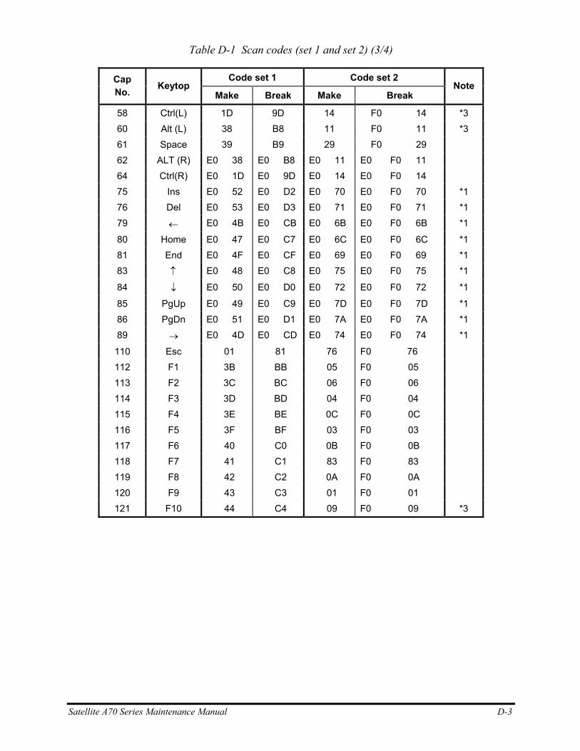
Satellite A70 Series Maintenance Manual D-3
Table D-1 Scan codes (set 1 and set 2) (3/4)
Code set 1 Code set 2 Cap No. Keytop
Make Break Make Break Note
58 Ctrl(L) 1D 9D 14 F0 14 *3 60 Alt (L) 38 B8 11 F0 11 *3 61 Space 39 B9 29 F0 29 62 ALT (R) E0 38 E0 B8 E0 11 E0 F0 11 64 Ctrl(R) E0 1D E0 9D E0 14 E0 F0 14 75 Ins E0 52 E0 D2 E0 70 E0 F0 70 *1 76 Del E0 53 E0 D3 E0 71 E0 F0 71 *1 79 ← E0 4B E0 CB E0 6B E0 F0 6B *1
80 Home E0 47 E0 C7 E0 6C E0 F0 6C *1 81 End E0 4F E0 CF E0 69 E0 F0 69 *1 83 ↑ E0 48 E0 C8 E0 75 E0 F0 75 *1
84 ↓ E0 50 E0 D0 E0 72 E0 F0 72 *1
85 PgUp E0 49 E0 C9 E0 7D E0 F0 7D *1 86 PgDn E0 51 E0 D1 E0 7A E0 F0 7A *1 89 → E0 4D E0 CD E0 74 E0 F0 74 *1
110 Esc 01 81 76 F0 76 112 F1 3B BB 05 F0 05 113 F2 3C BC 06 F0 06 114 F3 3D BD 04 F0 04 115 F4 3E BE 0C F0 0C 116 F5 3F BF 03 F0 03 117 F6 40 C0 0B F0 0B 118 F7 41 C1 83 F0 83 119 F8 42 C2 0A F0 0A 120 F9 43 C3 01 F0 01 121 F10 44 C4 09 F0 09 *3
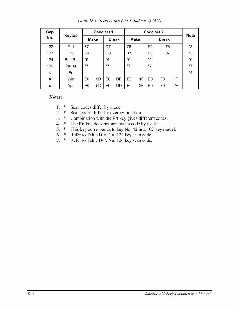
D-4 Satellite A70 Series Maintenance Manual
Table D-1 Scan codes (set 1 and set 2) (4/4)
Code set 1 Code set 2 Cap No. Keytop
Make Break Make Break Note
122 F11 57 D7 78 F0 78 *3 123 F12 58 D8 07 F0 07 *3 124 PrintSc *6 *6 *6 *6 *6 126 Pause *7 *7 *7 *7 *7 X Fn — — — — *4 X Win E0 5B E0 DB E0 1F E0 F0 1F x App E0 5D E0 DD E0 2F E0 F0 2F
Notes:
1. * Scan codes differ by mode. 2. * Scan codes differ by overlay function. 3. * Combination with the Fn key gives different codes. 4. * The Fn key does not generate a code by itself. 5. * This key corresponds to key No. 42 in a 102-key model. 6. * Refer to Table D-6, No. 124 key scan code. 7. * Refer to Table D-7, No. 126 key scan code.
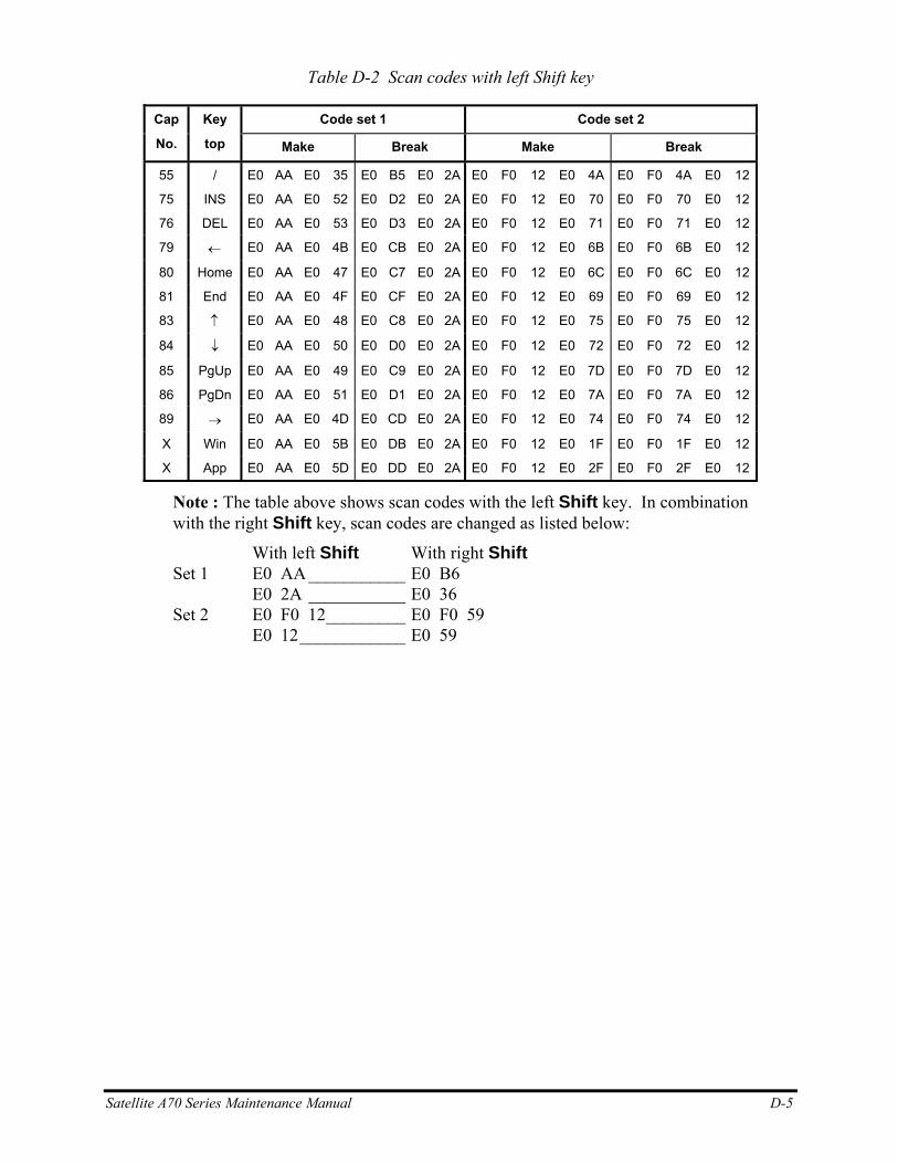
Satellite A70 Series Maintenance Manual D-5
Table D-2 Scan codes with left Shift key
Code set 1 Code set 2 Cap
No.
Key
top Make Break Make Break
55 / E0 AA E0 35 E0 B5 E0 2A E0 F0 12 E0 4A E0 F0 4A E0 12
75 INS E0 AA E0 52 E0 D2 E0 2A E0 F0 12 E0 70 E0 F0 70 E0 12
76 DEL E0 AA E0 53 E0 D3 E0 2A E0 F0 12 E0 71 E0 F0 71 E0 12
79 ← E0 AA E0 4B E0 CB E0 2A E0 F0 12 E0 6B E0 F0 6B E0 12
80 Home E0 AA E0 47 E0 C7 E0 2A E0 F0 12 E0 6C E0 F0 6C E0 12
81 End E0 AA E0 4F E0 CF E0 2A E0 F0 12 E0 69 E0 F0 69 E0 12
83 ↑ E0 AA E0 48 E0 C8 E0 2A E0 F0 12 E0 75 E0 F0 75 E0 12
84 ↓ E0 AA E0 50 E0 D0 E0 2A E0 F0 12 E0 72 E0 F0 72 E0 12
85 PgUp E0 AA E0 49 E0 C9 E0 2A E0 F0 12 E0 7D E0 F0 7D E0 12
86 PgDn E0 AA E0 51 E0 D1 E0 2A E0 F0 12 E0 7A E0 F0 7A E0 12
89 → E0 AA E0 4D E0 CD E0 2A E0 F0 12 E0 74 E0 F0 74 E0 12
X Win E0 AA E0 5B E0 DB E0 2A E0 F0 12 E0 1F E0 F0 1F E0 12
X App E0 AA E0 5D E0 DD E0 2A E0 F0 12 E0 2F E0 F0 2F E0 12
Note : The table above shows scan codes with the left Shift key. In combination with the right Shift key, scan codes are changed as listed below:
With left Shift With right Shift Set 1 E0 AA ___________ E0 B6 E0 2A ___________ E0 36 Set 2 E0 F0 12_________ E0 F0 59 E0 12____________ E0 59
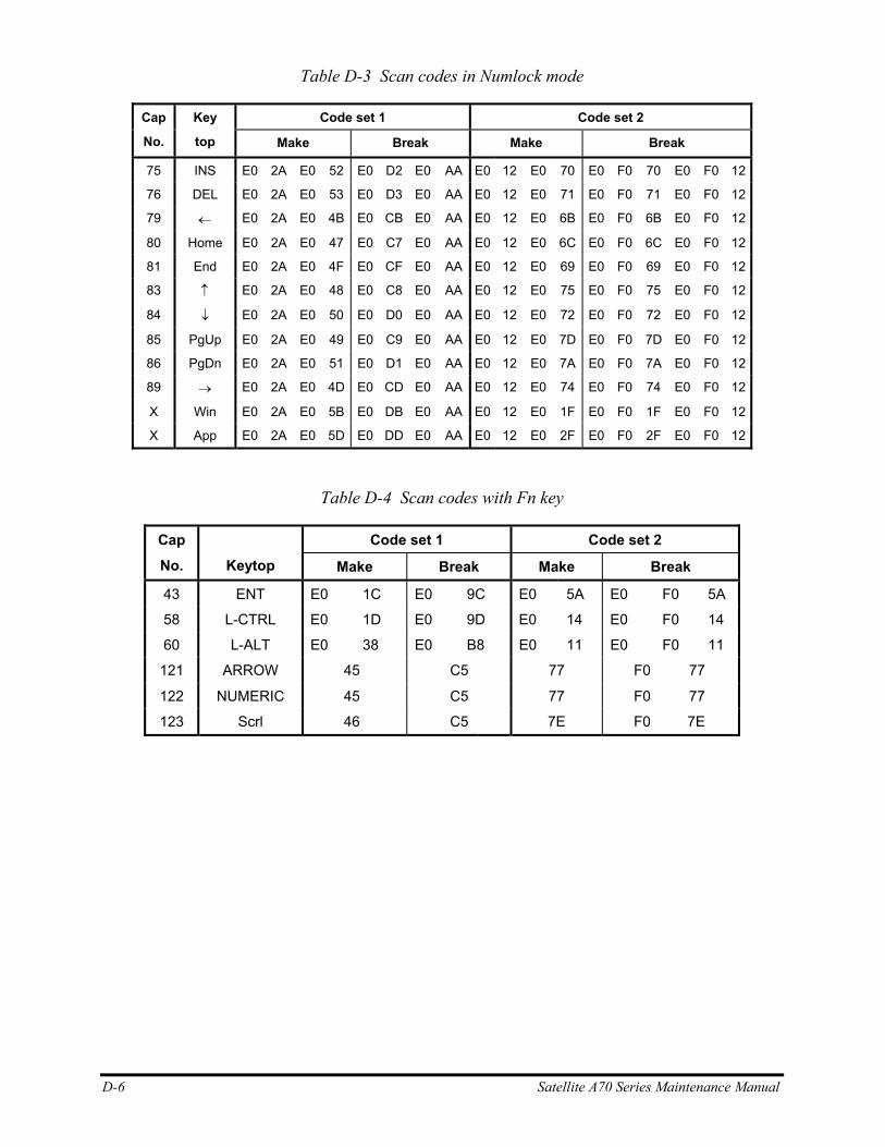
D-6 Satellite A70 Series Maintenance Manual
Table D-3 Scan codes in Numlock mode
Code set 1 Code set 2 Cap
No.
Key
top Make Break Make Break
75 INS E0 2A E0 52 E0 D2 E0 AA E0 12 E0 70 E0 F0 70 E0 F0 12
76 DEL E0 2A E0 53 E0 D3 E0 AA E0 12 E0 71 E0 F0 71 E0 F0 12
79 ← E0 2A E0 4B E0 CB E0 AA E0 12 E0 6B E0 F0 6B E0 F0 12
80 Home E0 2A E0 47 E0 C7 E0 AA E0 12 E0 6C E0 F0 6C E0 F0 12
81 End E0 2A E0 4F E0 CF E0 AA E0 12 E0 69 E0 F0 69 E0 F0 12
83 ↑ E0 2A E0 48 E0 C8 E0 AA E0 12 E0 75 E0 F0 75 E0 F0 12
84 ↓ E0 2A E0 50 E0 D0 E0 AA E0 12 E0 72 E0 F0 72 E0 F0 12
85 PgUp E0 2A E0 49 E0 C9 E0 AA E0 12 E0 7D E0 F0 7D E0 F0 12
86 PgDn E0 2A E0 51 E0 D1 E0 AA E0 12 E0 7A E0 F0 7A E0 F0 12
89 → E0 2A E0 4D E0 CD E0 AA E0 12 E0 74 E0 F0 74 E0 F0 12
X Win E0 2A E0 5B E0 DB E0 AA E0 12 E0 1F E0 F0 1F E0 F0 12
X App E0 2A E0 5D E0 DD E0 AA E0 12 E0 2F E0 F0 2F E0 F0 12
Table D-4 Scan codes with Fn key
Code set 1 Code set 2 Cap No.
Keytop Make Break Make Break
43 ENT E0 1C E0 9C E0 5A E0 F0 5A
58 L-CTRL E0 1D E0 9D E0 14 E0 F0 14
60 L-ALT E0 38 E0 B8 E0 11 E0 F0 11
121 ARROW 45 C5 77 F0 77
122 NUMERIC 45 C5 77 F0 77
123 Scrl 46 C5 7E F0 7E
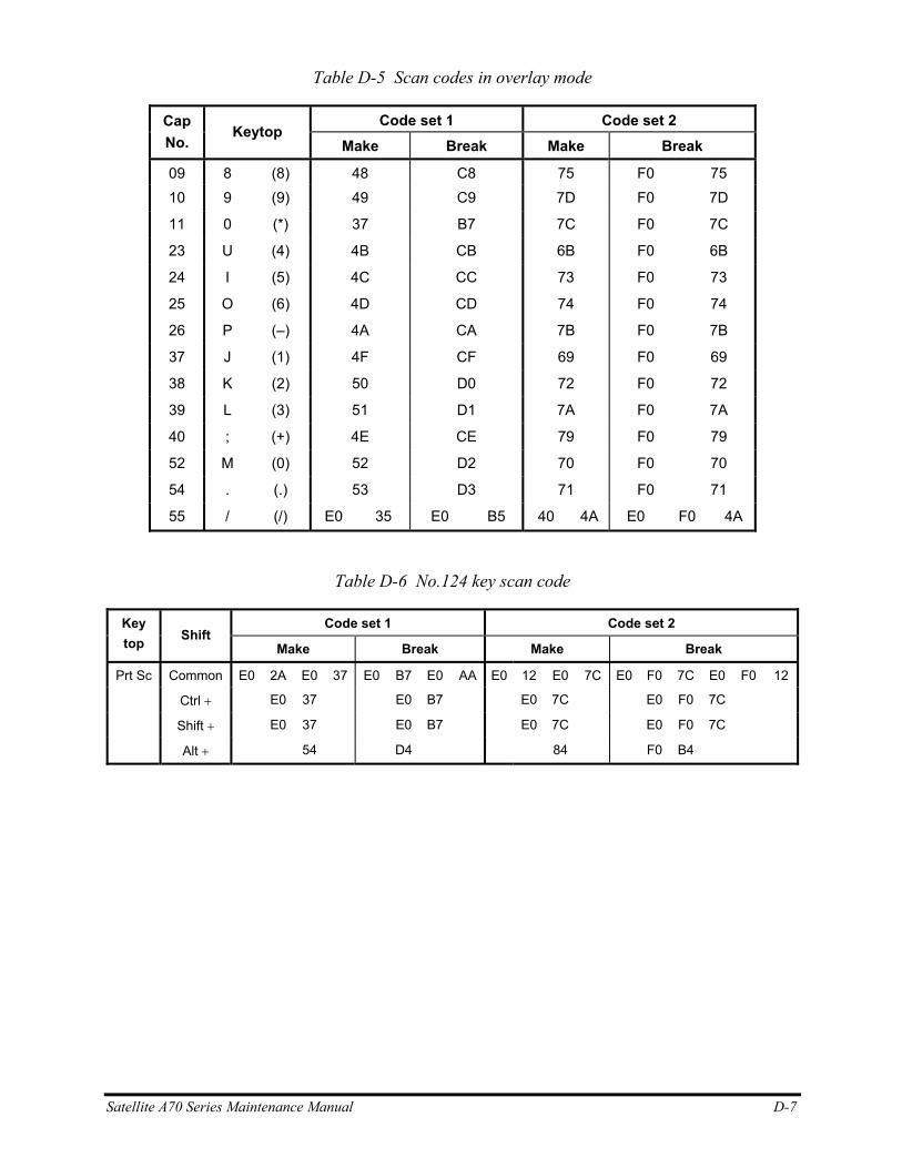
Satellite A70 Series Maintenance Manual D-7
Table D-5 Scan codes in overlay mode
Code set 1 Code set 2 Cap No.
Keytop Make Break Make Break
09 8 (8) 48 C8 75 F0 75 10 9 (9) 49 C9 7D F0 7D
11 0 (*) 37 B7 7C F0 7C
23 U (4) 4B CB 6B F0 6B
24 I (5) 4C CC 73 F0 73
25 O (6) 4D CD 74 F0 74
26 P (–) 4A CA 7B F0 7B
37 J (1) 4F CF 69 F0 69
38 K (2) 50 D0 72 F0 72
39 L (3) 51 D1 7A F0 7A
40 ; (+) 4E CE 79 F0 79
52 M (0) 52 D2 70 F0 70
54 . (.) 53 D3 71 F0 71
55 / (/) E0 35 E0 B5 40 4A E0 F0 4A
Table D-6 No.124 key scan code
Code set 1 Code set 2 Key top Shift
Make Break Make Break
Prt Sc Common E0 2A E0 37 E0 B7 E0 AA E0 12 E0 7C E0 F0 7C E0 F0 12
Ctrl + E0 37 E0 B7 E0 7C E0 F0 7C
Shift + E0 37 E0 B7 E0 7C E0 F0 7C
Alt + 54 D4 84 F0 B4
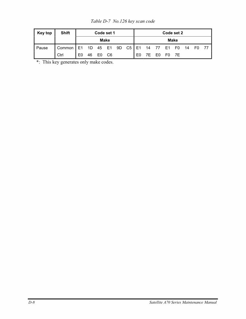
D-8 Satellite A70 Series Maintenance Manual
Table D-7 No.126 key scan code
Code set 1 Code set 2 Key top Shift
Make Make
Pause Common E1 1D 45 E1 9D C5 E1 14 77 E1 F0 14 F0 77
Ctrl E0 46 E0 C6 E0 7E E0 F0 7E
*: This key generates only make codes.
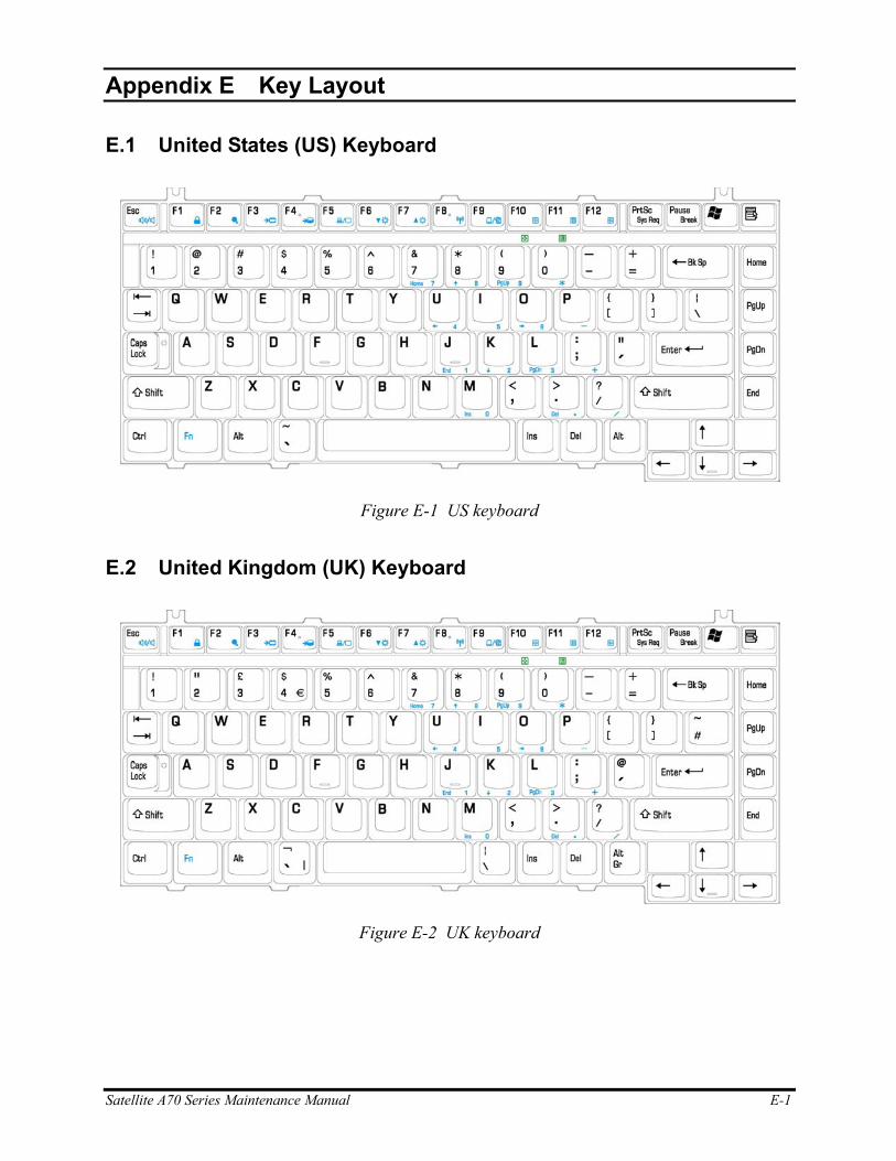
Appendix E
Appendix E Key Layout
E.1 United States (US) Keyboard
Figure E-1 US keyboard
E.2 United Kingdom (UK) Keyboard
Figure E-2 UK keyboard
Satellite A70 Series Maintenance Manual E-1
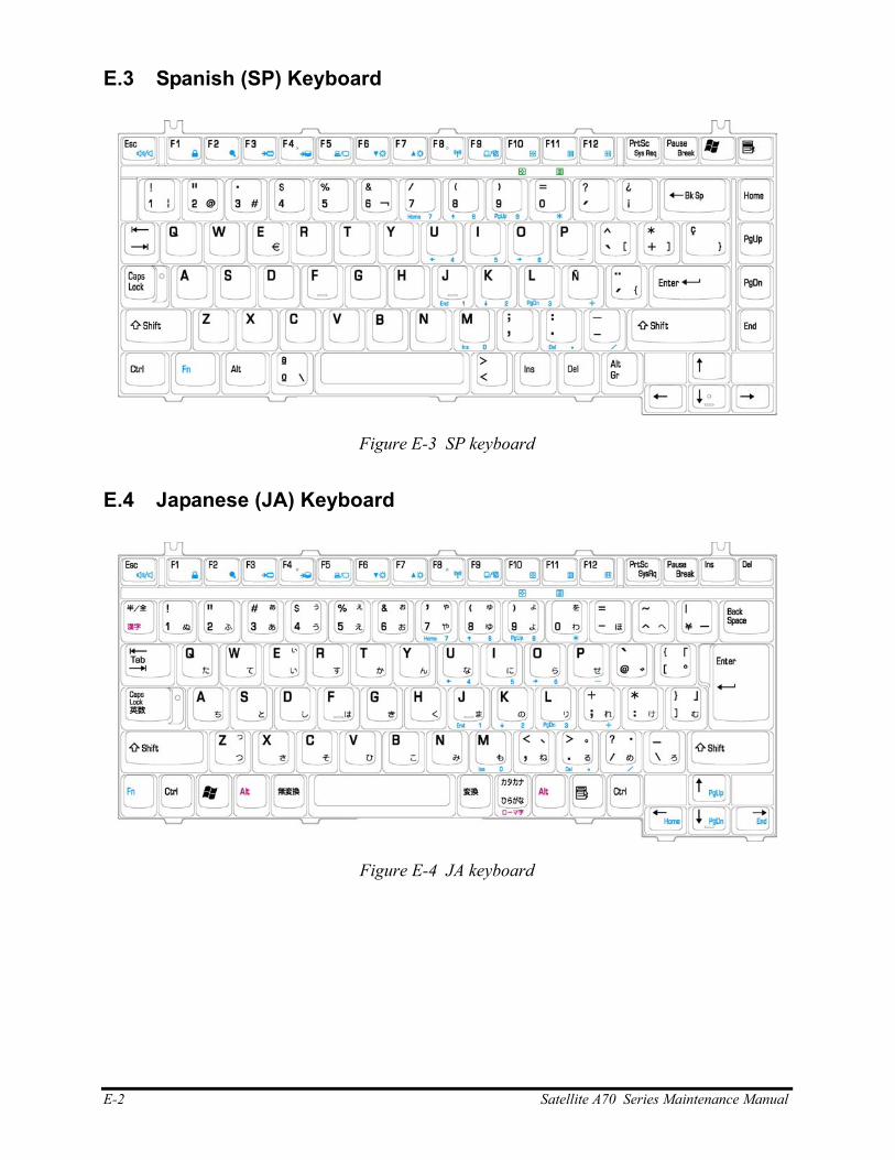
E.3 Spanish (SP) Keyboard
Figure E-3 SP keyboard
E.4 Japanese (JA) Keyboard
Figure E-4 JA keyboard
E-2 Satellite A70 Series Maintenance Manual
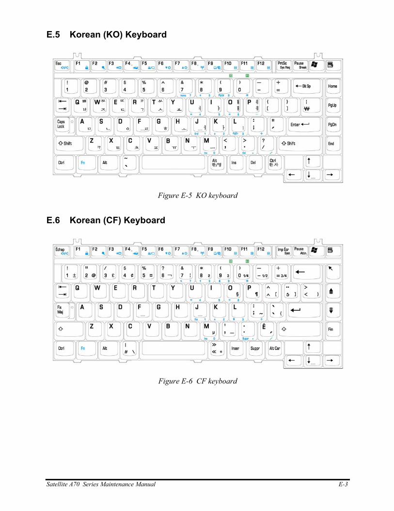
E.5 Korean (KO) Keyboard
Figure E-5 KO keyboard
E.6 Korean (CF) Keyboard
Figure E-6 CF keyboard
Satellite A70 Series Maintenance Manual E-3
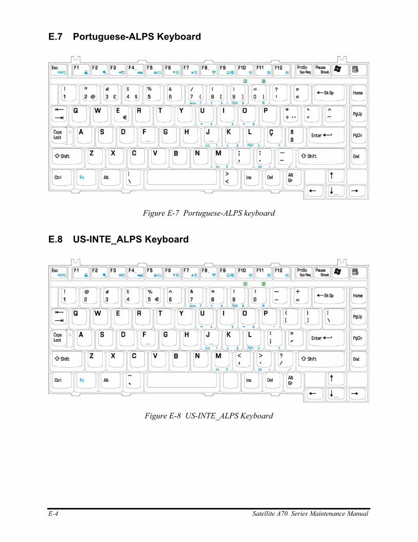
E.7 Portuguese-ALPS Keyboard
Figure E-7 Portuguese-ALPS keyboard
E.8 US-INTE_ALPS Keyboard
Figure E-8 US-INTE_ALPS Keyboard
E-4 Satellite A70 Series Maintenance Manual
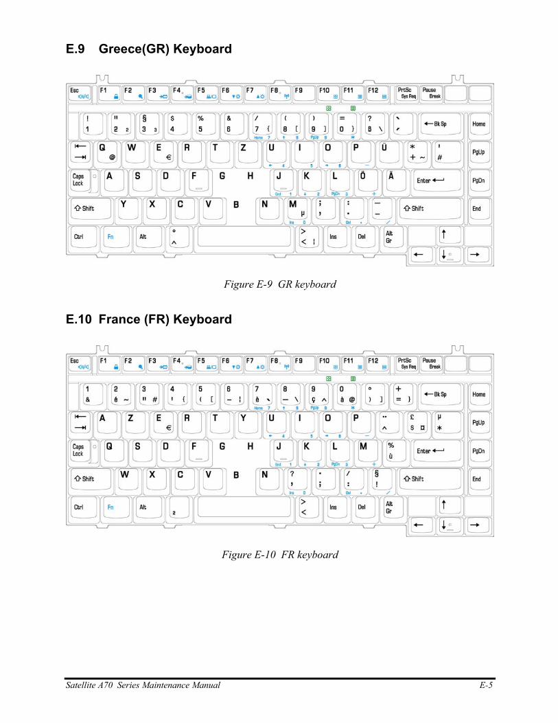
E.9 Greece(GR) Keyboard
Figure E-9 GR keyboard
E.10 France (FR) Keyboard
Figure E-10 FR keyboard
Satellite A70 Series Maintenance Manual E-5
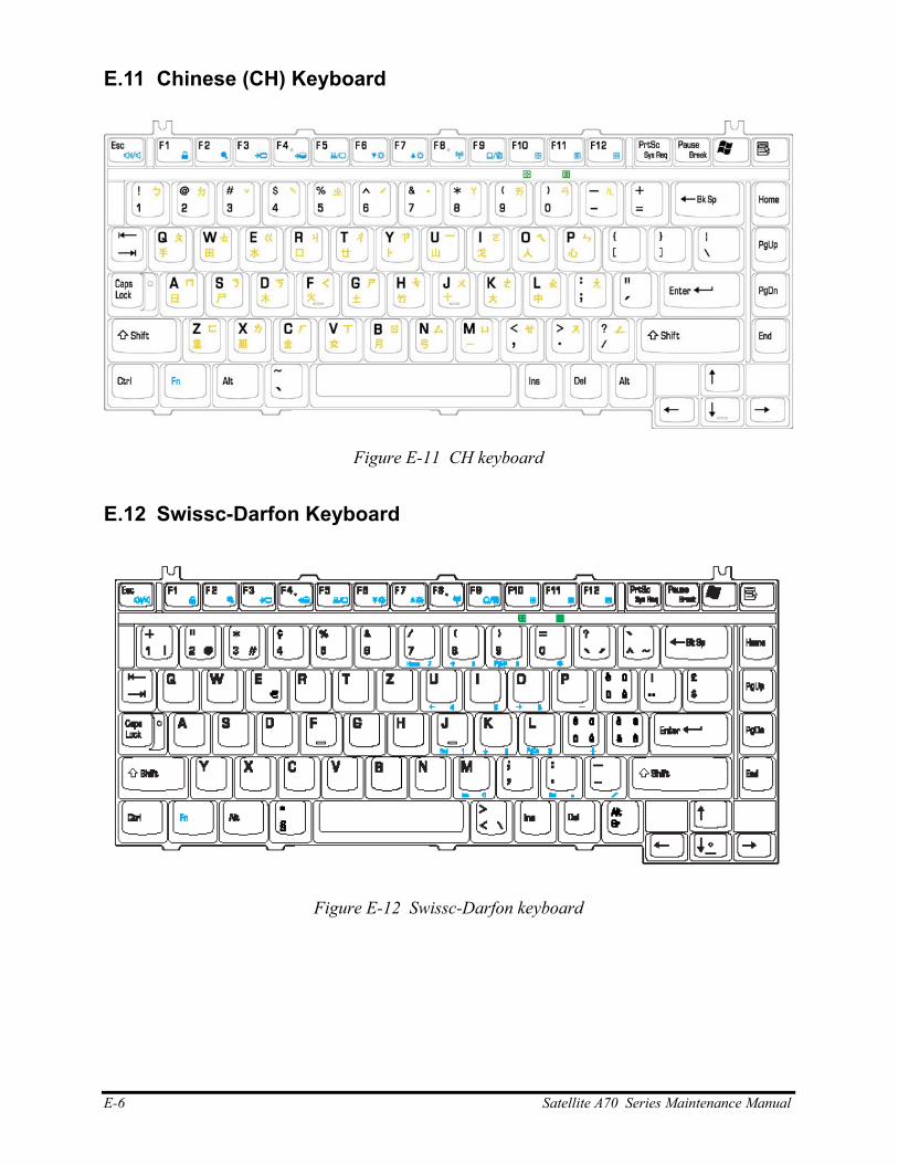
E.11 Chinese (CH) Keyboard
Figure E-11 CH keyboard
E.12 Swissc-Darfon Keyboard
Figure E-12 Swissc-Darfon keyboard
E-6 Satellite A70 Series Maintenance Manual
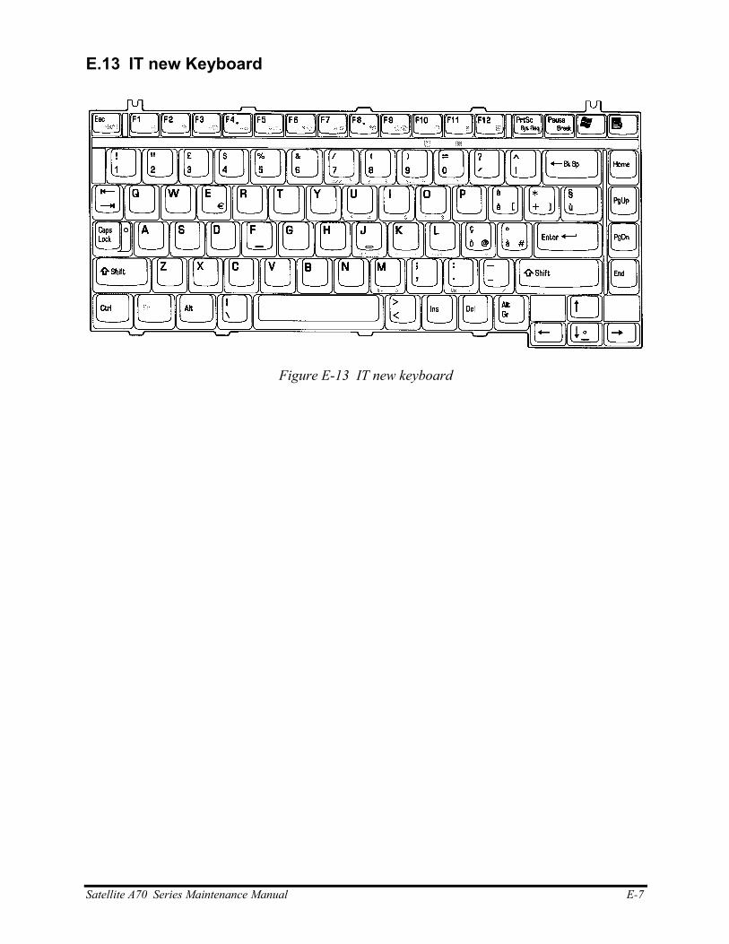
E.13 IT new Keyboard
Figure E-13 IT new keyboard
Satellite A70 Series Maintenance Manual E-7

E-8 Satellite A70 Series Maintenance Manual

F.
Appendix F Series Screw Torque List
Table F-1 Series Screw Torque List
SCREW P/N SCREW SPEC Q'ty LOCATION SCREW TORQUE
MAAA0015320 M2*3 6 LCD BRK TO LCDPANEL 1.2~1.5kg
MAAA0015320 M2*3 1 INVERTER TO COVER SUB ASSY 1.5~2.0kg
MAAA0015320 M2*3 1 LCD CABLE TO COVER SUB ASSY 1.5~2.0kg
MAC925003Z0 M2.5*3 1 LCD CABLE TO LOG UP 2.5~3.0kg
MMCK25050Z0 M2.5*5 2 LCD BRK ASSY TO
COVER SUB ASSY(R+L)
2.5~3kg
MMCK25050Z0 M2.5*5 2 LCD BEZEL ASSY TO COVER SUB
ASSY 2.5~3kg
MAC925003Z0 M2.5*3 2 KEYBOARD TO LOGIC ASSY 2.5~3.0kg
MMCK20050N0 M2*5 2 CARD BUS TO MB 1.5~2.0kg
MAAA0051400 M2*7 2 Card Bus to MB 1.5~2.0kg
MACK20003Z0 M2*13 2 HDD CONNT TO MB 1.5~2.0kg
MMCK20050N0 M2*5 2 CD ROM CONN TO MB 1.5~2.0kg
MAC925003Z0 M2.5*3 2 MDC TO MB 2.5~3kg
MACK25080Z0 M2.5*8 2 MB TO LOG LOWER 2.5~3kg
MAC925003Z0 M2.5X3 1 TRACK PAD BRK TO LOGIC UPPER 2.5~3kg
MMCK25030N0 M2.5X3 2 LED BOARD TO LOG UP 2.5~3kg
MMCK25050Z0 M2.5*5 2 SADDLE(R/L) TO
LOG UP SHIELD TO LOG UP
2.5~3kg
MAAA0015320 M2.0X3 4 SPEAKER L/R TO LOGIC UPPER 1.5~2kg
MAC925003Z0 M2.5*3 1 LOGIC UPPER TO STANDOFF TO MB 2.5~3kg
MACK25080Z0 M2.5*8 5 LOGIC UPPER TO LOG LOWER 2.5~3kg
MACK25080Z0 M2.5*8 2 LOG LOW-TO HINGE SADDLE R(L) 2.5~3kg
MACK25080Z0 M2.5*8 14 LOGIC LOWER TO LOGIC UPPER 2.5~3kg
MAC925003Z0 M2.5*3 2 LOGIC LOWER TO LOGIC UPPER 2.5~3kg
Satellite A70 Series Maintenance Manual F-1
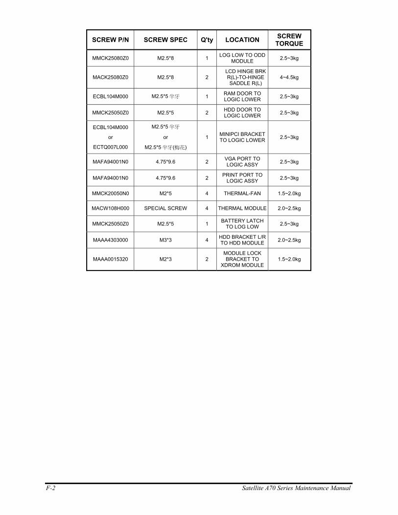
F-2 Satellite A70 Series Maintenance Manual
SCREW P/N SCREW SPEC Q'ty LOCATION SCREW TORQUE
MMCK25080Z0 M2.5*8 1 LOG LOW TO ODD MODULE 2.5~3kg
MACK25080Z0 M2.5*8 2 LCD HINGE BRK R(L)-TO-HINGE SADDLE R(L)
4~4.5kg
ECBL104M000 M2.5*5 半牙 1 RAM DOOR TO LOGIC LOWER 2.5~3kg
MMCK25050Z0 M2.5*5 2 HDD DOOR TO LOGIC LOWER 2.5~3kg
ECBL104M000
or
ECTQ007L000
M2.5*5 半牙
or
M2.5*5 半牙(梅花)
1 MINIPCI BRACKET TO LOGIC LOWER 2.5~3kg
MAFA94001N0 4.75*9.6 2 VGA PORT TO LOGIC ASSY 2.5~3kg
MAFA94001N0 4.75*9.6 2 PRINT PORT TO LOGIC ASSY 2.5~3kg
MMCK20050N0 M2*5 4 THERMAL-FAN 1.5~2.0kg
MACW108H000 SPECIAL SCREW 4 THERMAL MODULE 2.0~2.5kg
MMCK25050Z0 M2.5*5 1 BATTERY LATCH TO LOG LOW 2.5~3kg
MAAA4303000 M3*3 4 HDD BRACKET L/R TO HDD MODULE 2.0~2.5kg
MAAA0015320 M2*3 2 MODULE LOCK BRACKET TO
XDROM MODULE 1.5~2.0kg
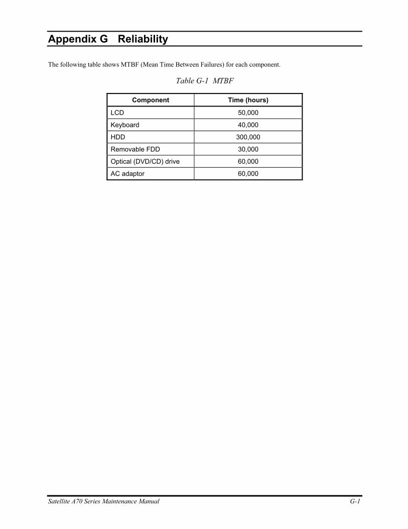
Appendix G
Appendix G Reliability
The following table shows MTBF (Mean Time Between Failures) for each component.
Table G-1 MTBF
Component Time (hours)
LCD 50,000
Keyboard 40,000
HDD 300,000
Removable FDD 30,000
Optical (DVD/CD) drive 60,000
AC adaptor 60,000
Satellite A70 Series Maintenance Manual G-1

G-2 Satellite A70 Series Maintenance Manual