toronto multi-use trail design guidelines · toronto multi-use trail design guidelines 1 figure...
TRANSCRIPT

Toronto Multi-Use Trail Design Guidelines 1Figure 3.08: Lateral clearances for rest stops or other trail amenity areas
1.0m min. Bench Clearance
1.0m min. Trail Clearance
Interpretation Signage
Area of SpecialInterest
Fence
Shade Tree
TORONTO MULTI-USE TRAIL DESIGN GUIDELINES
Transportation ServicesParks, Forestry & Recreation January 2015

2 Toronto Multi-Use Trail Design Guidelines
Figure 3.08: Lateral clearances for rest stops or other trail amenity areas
1.0m min. Bench Clearance
1.0m min. Trail Clearance
Interpretation Signage
Area of SpecialInterest
Fence
Shade Tree
Toronto Multi-Use Trail Design Guidelines iFigure 3.08: Lateral clearances for rest stops or other trail amenity areas
1.0m min. Bench Clearance
1.0m min. Trail Clearance
Interpretation Signage
Area of SpecialInterest
Fence
Shade Tree
Waterfront Trail at Marie Curtis Park
AcknowledgementsThe Toronto Multi-use Trail Guidelines are a joint project of the City of Toronto’s Transportation Services and Parks, Forestry and Recreation Divisions. The following individuals and their organizations are recognized here for their contribution to the development of these guidelines.
CONSULTANT TEAM
Victor Ford and Associates Inc Landscape ArchitectsVictor Ford, OALA, CSLA, ASLAJeremy Craig Lori PhilpMehran Ataee Jocelyn Hirtes
with support from Bríd Ní Leidhin, Cole Engineering Group Limited
STEERING COMMITTEE
Transportation ServicesDaniel Egan, Manager; Cycling Infrastructure & ProgramsJennifer Hyland, Transportation Planner; Cycling Infrastructure & ProgramsSibel Sarper, Assistant Planner; Cycling Infrastructure & Programs
Parks, Forestry & RecreationAlex Shevchuk, Project Manager, Landscape Architecture Unit; Planning, Design & DevelopmentStewart McIntosh, Landscape Architect; Landscape Architecture Unit; Planning, Design & DevelopmentRuthanne Henry, Project Co-ordinator; Parks Development & Capital ProjectsWendy Strickland, Natural Environment Specialist; Natural Environment & Community Programs
TECHNICAL ADVISORY COMMITTEE
City PlanningHamish Goodwin, Urban Designer; Civic Design; City Planning / Design Review Panel CoordinatorKristina Reinders, Urban Designer; Civic Design; City Planning
Engineering and Construction ServicesPenelope Palmer, Senior Engineer, Capital Works Delivery A Emergency Medical ServicesCindy Taber, Superintendent Operations, EMS Program Development and Professional Services

ii Toronto Multi-Use Trail Design Guidelines
Figure 3.08: Lateral clearances for rest stops or other trail amenity areas
1.0m min. Bench Clearance
1.0m min. Trail Clearance
Interpretation Signage
Area of SpecialInterest
Fence
Shade Tree
Toronto Multi-Use Trail Design Guidelines iiiFigure 3.08: Lateral clearances for rest stops or other trail amenity areas
1.0m min. Bench Clearance
1.0m min. Trail Clearance
Interpretation Signage
Area of SpecialInterest
Fence
Shade Tree
Parks, Forestry & RecreationTara Coley, Project Coordinator; Standards & Innovation
Carol Cormier, Manager; Standards & Innovation
James Dann, Manager; Parks – Waterfront District
Norman DeFraeye, Supervisor; Ravine and Natural Features Protection
Lori Ellis, Planner; Central Waterfront Planning & Design
Ed Fearon, Program Standards & Development Oficer; Standards & Innovation
Diane Leal, Urban Forestry Planner; Ravine and Natural Features Protection
Roger Macklin, General Supervisor; Parks – North York District
Jamie Warren, General Supervisor, Technical; Parks – North York District
Lorene Bodiam, Program Standards & Development Oficer; Community Development
Policy, Planning, Finance & AdministrationMaogosha Pyjor, Senior Public Consultation Coordinator; Public Consultation
Public HealthRich Whate, Consultant, Health Promotion
Solid WasteEugene Benda, Supervisor; Landill Monitoring; Municipalities & Services
Toronto and Region Conservation AuthorityMike Bender, Manager, Conservation Lands
Adam Szalarski, Acting Conservation Lands Coordinator
Brittany Reid, Landscape and Trail Designer, Conservation Lands
PREFACEBackgroundPolicy
1. INTRODUCTION1.1. Scope | Application1.2. Guiding Principles1.3. Sound Design Judgement
2. MULTI-USE TRAIL CLASSIFICATION
3. GEOMETRIC DESIGN FOR MULTI-USE TRAILS3.1. Trail Users3.2. Design Users3.3. Volume of Users3.4. Mix of Users3.5. Site Features3.6. Special Uses
4. TYPICAL TRAIL DESIGN4.1. Design Condition4.2. Trail Conigurations4.3. Trail Width and Surface 4.4. Trail Edge Conditions4.5. Vertical Clearances4.6. Slopes4.7. Curves4.8. Existing, Non-conforming Trails
5. TRAIL CROSSINGS5.1. Trail Intersections5.2. Crossing Roads 5.3. Park Roads and Driveways
6. TRAILS IN SPECIAL SITUATIONS 6.1. Strategies for Multi-use Trail Development with Challenging or Constrained Site Conditions 6.2. Constructing Trails in Challenging Site Conditions6.3. Trails through Natural Areas6.4. Special Restrictions6.5 Multi-use Trails in Park Roads and Parking Lots6.6 Vehicular Access Control
7. DESIGN FOR MULTI-USE TRAIL ELEMENTS AND AMENITIES7.1. Signage and Wayinding7.2. Grade Separations and Structures7.3. Lighting7.4. Resting and Viewing Areas7.5. Trailheads7.6. Passing Areas7.7. Site Furnishings7.8 Personal Security7.9. Temporary Conditions 8. CONSTRUCTION OF MULTI-USE TRAILS
9. MAINTENANCE CONSIDERATIONS FOR MULTI-USE TRAILS
viii viii viii
11 1 1
3
7
7 8 9
10 10 11
13 13 14 22 23 27 28 28 32
3535 40 57
5959
61
65 68 71
74
77
77 83 86 87 89 89 90 94 95
96
99
ContentsAcknowledgements, continued Toronto WaterBill Snodgrass, Senior Engineer; Stormwater Management; Water Infrastructure Management
Transportation ServicesJohanna Kyte, Project Lead; Public Realm – Beautiful Streets Program
Marko Oinonen, Manager, Trafic Operations – Scarborough District
Jackie Parissi, Supervisor, Street & Expressway Lighting – Trafic Plant Installation & Maintenance
Chris Ronson, Project Manager; Public Realm -- Pedestrian Projects
Rob Watson, Project Oficer; Public Realm – Beautiful Streets Program
PARTICIPATING STAKEHOLDER ORGANIZATIONSCanada Bikes
City of Mississauga, Parks Forestry Division, Community Services and Cycling Ofice
Cycle Toronto, Trails Working Group and Cycle 26
Etobicoke South Cycling Committee
Gooderham & Worts Neighbourhood Association
Hydro One Networks Inc., Facilities and Real Estate
Metrolinx, Policy, Planning and Innovation
Ministry of Tourism, Culture, Sport – Ontario Trails Strategy Ministry of Transportation -- Ontario
City of Toronto – Parks, Forestry, and Recreation Division Community Disability Steering Committee
PEL Consulting
Todmorden Mills Wildlower Preserve
Toronto Field Naturalists
Toronto Green Community
Toronto Trailblazers
Walk Toronto
Waterfront Regeneration Trust

iv Toronto Multi-Use Trail Design Guidelines
Figure 3.08: Lateral clearances for rest stops or other trail amenity areas
1.0m min. Bench Clearance
1.0m min. Trail Clearance
Interpretation Signage
Area of SpecialInterest
Fence
Shade Tree
Toronto Multi-Use Trail Design Guidelines vFigure 3.08: Lateral clearances for rest stops or other trail amenity areas
1.0m min. Bench Clearance
1.0m min. Trail Clearance
Interpretation Signage
Area of SpecialInterest
Fence
Shade Tree
List of Figures Figure 2.01. multi-use trail classiication chart
Figure 4.01 multi-use trail condition chartFigure 4.02: secondary trail conigurationFigure 4.03: primary trail conigurationFigure 4.04: high-capacity trail - wide trail conigurationFigure 4.05: high-capacity trail coniguration with pedestrian-only area/promenade/sidewalkFigure 4.06: high-capacity trail coniguration with separated pedestrian-only areaFigure 4.07: high-capacity trail - segregated-use conigurationFigure 4.08: high-capacity trail -- twinned conigurationFigure 4.09: typical trail construction Figure 4.10: dimensions of trail clearances Figure 4.11: slopes or drop-offs parallel to trailFigure 4.12: example of clearance and mitigation for trails with edge obstructionFigure 4.13: curb-side zonesFigure 4.14: vertical clearancesFigure 4.15: maximum cross-slopes Figure 4.16: maintenance markers for curve clearancesFigure 4.17: horizontal curves: 30 km/h bicycle design speed with no mitigation measuresFigure 4.18: horizontal curves: 20 km/h bicycle design speed with mitigation measuresFigure 4.19: horizontal curves: 30 km/h bicycle design speed with mitigation measures
Figure 5.01: alignments for trail crossingsFigure 5.02: crossing of two trails of similar widthFigure 5.03: crossing of two trails of different widthsFigure 5.04: T-intersection of two trailsFigure 5.05: lateral clearance for two merging trailsFigure 5.06: mixed crossrideFigure 5.07: enhancement options for mixed crossridesFigure 5.08: combined crossride comprised of zebra stripes and elephant’s feetFigure 5.09: separated crossride comprised of double zebra stripes and elephant’s feetFigure 5.10: asymmetrical separated crossride comprised of zebra stripes and elephant’s feetFigure 5.11: pavement word markings Figure 5.12: trail crossing at intersection (signalized example with asymmetrical separated crossride)Figure 5.13: trail crossing at intersection (signalized example with combined crossride)Figure 5.14: trail crossing at intersection (all way stop controlled example with asymmetrical separated crossride)Figure 5.15: trail crossing at intersection (all way stop controlled example with mixed crossride)
Figure 5.16: mid-block crossing conigurations (signalized examples)Figure 5.17: mid-block crossing coniguration (unsignalized examples)Figure 5.18: unsignalized crossing coniguration of a trail and a roadway rampFigure 5.19: typical park road / driveway crossings: design options
Figure 6.01: preferred design for trails on slopesFigure 6.02: typical trail construction in wet soil areasFigure 6.03: trail design conigurations for wet soil areasFigure 6.04: trail crossing at active railwayFigure 6.05: trails through or adjacent to parking lots Figure 6.06: vehicular access control options
Figure 7.01a: placement of signageFigure 7.01b: placement of infoboard Figure 7.02: signage table Figure 7.03: signage guide plan
All igures prepared by Victor Ford and Associates Inc, with the exception of the map on the rear overleaf, which has been prepared by Victor Ford and Associates Inc using mapping provided by City of Toronto Transportation Services, Cycling Infrastructure & Programs.
Photo Credit:All photographs by Victor Ford and Associates Inc

Figure 3.08: Lateral clearances for rest stops or other trail amenity areas
1.0m min. Bench Clearance
1.0m min. Trail Clearance
Interpretation Signage
Area of SpecialInterest
Fence
Shade Tree
Toronto Multi-Use Trail Design Guidelines viiFigure 3.08: Lateral clearances for rest stops or other trail amenity areas
1.0m min. Bench Clearance
1.0m min. Trail Clearance
Interpretation Signage
Area of SpecialInterest
Fence
Shade Tree
Toronto Multi-Use Trail Design Guidelines
View along the Don Trail
These Guidelines will assist the City of Toronto in the development and ongoing maintenance of multi-use trails throughout the city. The guidelines respond to the urban context of Toronto’s trails and their varied locations in city boulevards, ravines, parkland, and rail and hydro corridors. These guidelines are consistent with current, relevant City and Provincial guidelines and policy documents, as well as with current North American and international best practices. In some cases, these guidelines make recommendations that exceed existing guidelines and best practices, to create truly world-class multi-use trails for Toronto’s residents and visitors.
BackgroundIn June 2012, Toronto City Council adopted the Bikeway Trails Implementation Plan1 a planning document which is the basis for moving forward with new multi-use trail development within the city. The Plan calls for 77 kilometres of new trails to be built within a ten-year time frame. The Plan also identiies priorities for upgrades to the city’s existing trail network and a plan for consistency in maintenance practices. The Plan provides a program that supports future trail building. One element of that program is the development of these Multi-Use Trail Design Guidelines.
PolicyThe City of Toronto Oficial Plan2 recognizes that the city-wide bike network, which includes the multi-use trail system, is a key element of the City’s transportation network. These Guidelines support implementation of the Oficial Plan by helping to develop a safe and comfortable environment that encourages people of all ages to choose active transportation for everyday mobility and enjoyment.
Oficial Plan references:2.2 Structuring Growth in the City: Integrating Land Use and Transportation
2.4 Bringing the City Together: A Progressive Agenda of Transportation Change, Policy 7(a)
The City of Toronto Parks Plan 2013-20173 identiies four key themes (page vi)1. Communicate and connect with users
2. Preserve and promote nature
3. Maintain quality parks
4. Improve system planning
Preface
1 http://www1.toronto.ca/City%20Of%20Toronto/Policy,%20Planning,%20Finance%20&%20Administration/Public%20Consultation%20Unit/Studies/Transportation/East%20Don%20Trail/Files/PDF/trails_project_table.pdf
2 http://www1.toronto.ca/wps/portal/contentonly?vgnextoid=03eda07443f36410VgnVCM10000071d60f89RCRD
3 http://www.toronto.ca/legdocs/mmis/2013/pe/bgrd/backgroundile-57282.pdf

viii Toronto Multi-Use Trail Design Guidelines
Figure 3.08: Lateral clearances for rest stops or other trail amenity areas
1.0m min. Bench Clearance
1.0m min. Trail Clearance
Interpretation Signage
Area of SpecialInterest
Fence
Shade Tree
Figure 3.08: Lateral clearances for rest stops or other trail amenity areas
1.0m min. Bench Clearance
1.0m min. Trail Clearance
Interpretation Signage
Area of SpecialInterest
Fence
Shade Tree
Toronto Multi-Use Trail Design GuidelinesView along the Gatineau Hydro Corridor Trail, near McCowan Road
Of these, the signiicant theme for trail planning and design is number 4, “Improve system planning,” which includes the following exerpted clauses:
10.4 Complete a comprehensive inventory and mapping of parks, trails and assets
11.2 Develop policies, standards and measures to support the appropriate use of parks and trails that guide planning, design, space allocation and permitting, and that address emerging and exclusive uses
11.3 Improve and coordinate trail mapping, classiication, maintenance, way-inding and connections to other public realm elements
12.2 Ensure that parks and trails meet or exceed provincial accessibility requirements
These guidelines support all of these measures by:
• providing tools for creating a detailed inventory of existing and planned trails and related assets;
• providing tools to standardize the process for planning and designing trails;
• providing tools--including a new trail classiication system--that that will allow city staff to better coordinate trail mapping, classiication, maintenance, way-inding and connections to other public realm elements; and
• providing a design and planning tool that incorporates best practices for universal design that meet or exceed provincially-mandated requirements.

x Toronto Multi-Use Trail Design Guidelines
Figure 3.08: Lateral clearances for rest stops or other trail amenity areas
1.0m min. Bench Clearance
1.0m min. Trail Clearance
Interpretation Signage
Area of SpecialInterest
Fence
Shade Tree
Toronto Multi-Use Trail Design Guidelines 1Figure 3.08: Lateral clearances for rest stops or other trail amenity areas
1.0m min. Bench Clearance
1.0m min. Trail Clearance
Interpretation Signage
Area of SpecialInterest
Fence
Shade Tree
1 These guidelines have been developed for Toronto Transportation Services and Toronto Parks, Forestry and Recreation. Many stakeholders have been consulted and a broad literature review conducted to ensure that this document will be a useful and practical resource, with ahead-of-the-curve guidance for trail planners, designers and operators in Toronto and elsewhere.
While these guidelines may be broadly applicable for the design of any multi-use trail, it is important to note that they have been developed primarily as a resource for the design and operation of a speciic network of multi-use trails in Toronto (see rear overleaf for current network map).
These are not local park walkways or natural environment trails, and they are also not dedicated bicycle lanes.
These are hard-surfaced, off-road routes that form a network of active transportation options across the City, with on-road bikeways, sidewalks and park paths. They also provide a signiicant recreation asset. All facilities forming part of this network should be considered to be shared among many kinds of users.
Introduction
1.1. Scope | Application
The following guiding principles have been developed in order to evaluate the success of these guidelines and of trails that may be developed by following them.
Consistency and ExcellenceMULTI-USE TRAILS should be consistently designed, constructed and maintained, in accordance with clearly-deined guidelines that meet current and evolving best practices, as a minimum. Wherever possible, Toronto’s MULTI-USE TRAILS should strive to exceed existing best practices and “raise the bar” for excellence.
Safety, Security and ComfortThe SAFETY, SECURITY and COMFORT of all trail users are primary considerations for the design, construction and maintenance of MULTI-USE TRAILS.
AccessibilityAll people are welcome on Toronto’s MULTI-USE TRAILS, regardless of ability. The design, construction and maintenance of these facilities must strive to adhere to the principles of Universal Design, and to exceed relevant regulations wherever possible.
SustainabilityMULTI-USE TRAILS should be designed, constructed and maintained in the most sustainable ways possible: accommodating existing and anticipated volumes of users and making use of sustainable building and maintenance technologies wherever possible.
Environmental ProtectionAs many MULTI-USE TRAILS exist within sensitive natural environments, it is important that the design, construction, use, and maintenance of these facilities minimize impacts and disruptions within and adjacent to the trail corridor.
1.2. Guiding PrinciplesDesigners and decision-makers should exercise every effort to comply with these guidelines whenever possible. Situations may arise where a designer’s judgment may be that the guideline should be exceeded, and in other situations, a designer’s judgment may determine that there are sound reasons that a design may be considered appropriate despite a certain guideline not being met. In these cases, designers should reasonably and carefully limit the departures from the guideline, document the reasons for them, and provide suitable mitigation measures.
1.3. Sound Design Judgement
View along Highland Creek Trail, near Colonel Danforth Park
Pedestrians enjoying the Don Mills Trail

Figure 3.08: Lateral clearances for rest stops or other trail amenity areas
1.0m min. Bench Clearance
1.0m min. Trail Clearance
Interpretation Signage
Area of SpecialInterest
Fence
Shade Tree
Toronto Multi-Use Trail Design Guidelines 3Figure 3.08: Lateral clearances for rest stops or other trail amenity areas
1.0m min. Bench Clearance
1.0m min. Trail Clearance
Interpretation Signage
Area of SpecialInterest
Fence
Shade Tree
Toronto Multi-Use Trail Design Guidelines
The trail classiication system described in this chapter is intended to provide a simple method of categorizing multi-use trails based on their function in Toronto’s networks of active transportation facilities and parks. The classiication of trails facilitates a family of design options that are presented in the following chapters.
Toronto’s trails form a dense network throughout the city. Taken together with the city’s parks and open spaces, sidewalks and on-road bicycle facilities; this network forms part of a greater network of active transportation and recreation choices for Toronto’s residents and visitors.
Within this network, each trail, park, bicycle lane or other component has a particular role to play. As a result, each trail needs to have certain characteristics to ensure that it can perform appropriately. Three classes of trails are identiied by their role in the network:
Secondary trails connect between destinations within a small geographic area, or act as feeder or tributary routes for larger trails. They are similar to local or collector roads in the road classiication system, or to parkettes and neighbourhood parks in the parks network.
Primary trails connect between destinations in different parts of the city, and will often connect with each other, providing perhaps the most signiicant level of connectivity among the three types. They are similar to arterial roads in the road classiication system, or to community and district parks in the parks network. The majority of multi-use trails in Toronto are in this category.
2 Trail Classiication
View along the Finch Hydro Corridor Trail, looking west from near Sentinel Road
Example of a primary trail: Finch Hydro Corridor Trail, near the intersection of McNicoll Avenue and Middleield Road
Example of a secondary trail in G Ross Lord Park

4 Toronto Multi-Use Trail Design Guidelines
Figure 3.08: Lateral clearances for rest stops or other trail amenity areas
1.0m min. Bench Clearance
1.0m min. Trail Clearance
Interpretation Signage
Area of SpecialInterest
Fence
Shade Tree
Toronto Multi-Use Trail Design Guidelines 5Figure 3.08: Lateral clearances for rest stops or other trail amenity areas
1.0m min. Bench Clearance
1.0m min. Trail Clearance
Interpretation Signage
Area of SpecialInterest
Fence
Shade Tree
2 SECONDARY
PRIMARY
HIGH-CAPACITY
local connections
catchment area: smallestuser volumes: lowestmix of user-types: averagesite features: typicalspecial uses: noneseasonal variation: typical
catchment area: largeuser volumes: medium to highmix of user-types: average
catchment area: largest user volumes: highestmix of user-types: varies
feeder or tributary routes
connects different parts of the citycollects traffic from secondary trailsconnects with other primary trails
may perform any or all of the functionsof primary and/or secondary trails
collects traffic from primary and secondary trails
trail may be a destination or attractionitself
seasonal variation: atypical patterns of use depending upon site features present
special uses: various special uses may be accommodated including those that may require temporary closures or special permits
site features: significant attractions, features, and/or amenities may be present
special uses: special uses may occur if no closure is required
site features: minor features or amenities may be present
seasonal variation: typical
Figure 2.01. multi-use trail classiication chart
High-capacity trails provide a special function in the network. In the simplest sense, they accommodate the highest number of users, and can be compared to the expressways in the road network or to large “City Parks” in the park network. High-capacity trails address a broader concept of “capacity” than simply greater size or volume, however, and they do not imply greater speed. They connect to signiicant destinations within the city and can be utilized to accommodate a wider range or unusual distribution of user-types, to perform special functions, or to address particular site conditions. Notably, high-capacity trails may be destinations or attractions themselves.
With any attempt to classify diverse elements, there will be some level of overlap evident among the actual facilities, and some examples of non-conformance. This should not pose a signiicant problem, as the various design conigurations presented later incorporate the possibility of overlap, and are capable of bridging most gaps.
New trails will be designed to it within these classiications. Identiication of the classes of existing trails has already taken place, but may need to be applied to new trails, or reined as the city evolves over time. The map provided in the overleaf at the end of these guidelines provides a snapshot of the trail system in autumn, 2014.
Example of a high-capacity trail: Martin Goodman Trail waterfront promenade in Marilyn Bell Park (south-west of Exhibition Place)

Figure 3.08: Lateral clearances for rest stops or other trail amenity areas
1.0m min. Bench Clearance
1.0m min. Trail Clearance
Interpretation Signage
Area of SpecialInterest
Fence
Shade Tree
Toronto Multi-Use Trail Design Guidelines 7Figure 3.08: Lateral clearances for rest stops or other trail amenity areas
1.0m min. Bench Clearance
1.0m min. Trail Clearance
Interpretation Signage
Area of SpecialInterest
Fence
Shade Tree
Toronto Multi-Use Trail Design Guidelines
22 3 General Design ConsiderationsThe comfort and safety of trail users will be served by facilities that anticipate how different types of users behave on a trail, how many users may be present at a time of peak use, and whether they are all travelling by the same mode or using the trail for the same purpose.
3.1. Trail UsersToronto’s multi-use trails are utilized by residents and visitors throughout the year in many ways. A discussion of trail users must take in not only the growing number of trail users, but their growing variety as well. While the prevalent uses of trails may not be experiencing a signiicant shift, the subtle changes are useful to observe, especially where potential conlicts or incompatibilities may arise between different uses.
Modes of travel are becoming more diverse, with in-line skating, scooters, pedal-bikes, recumbent bicycles, skateboards, longboards and many other non-motorized ways of moving around appearing on trails. These are probably not going to compete with pedestrians and cyclists for sheer numbers, but their increasing presence is worth consideration, and supports designing trails that are capable of accommodating different users.
Purposes or trip purposes have most often been viewed from a cyclist lens, with commuter, recreational and touring being the usual categories. This remains a useful simpliication, however a broader view can take in signiicant users who may appear in smaller numbers but have a signiicant impact. These include hikers, joggers, dog-walkers, cycle-couriers (with or without cargo bikes and trailers) child-care workers and their carriages, school groups and others.
In Toronto, all multi-use trails are intended to be used for all purposes. These trails are not considered to be only recreational or only commuter trails.
Age of trail users, and skill and comfort level are often considered together. Providing trails that are inviting and safe for users of all ages, skills and comfort levels, should be a priority for designers.
East Don Trail in Charles Sauriol Conservation Area, near Milne Hollow
In-line skater on the Lower Don Trail

8 Toronto Multi-Use Trail Design Guidelines
Figure 3.08: Lateral clearances for rest stops or other trail amenity areas
1.0m min. Bench Clearance
1.0m min. Trail Clearance
Interpretation Signage
Area of SpecialInterest
Fence
Shade Tree
Toronto Multi-Use Trail Design Guidelines 9Figure 3.08: Lateral clearances for rest stops or other trail amenity areas
1.0m min. Bench Clearance
1.0m min. Trail Clearance
Interpretation Signage
Area of SpecialInterest
Fence
Shade Tree
3
3.3. Volume of UsersTrails are expected to exhibit typical patterns of use during the day that generally adhere to certain patterns. These patterns generally relate to the traditional work-day and work-week, the school calendar, and the seasons. Factors unique to every trail will result in slight variations, even on different parts of the same trail.
3.2. Design UsersGeometric design of trails typically follows from an assessment of the anticipated users and their characteristics as they move along a trail. For different aspects of trail design, it is common practice to identify a design user whose characteristics place the greatest demand on any particular aspect of trail geometry.
These guidelines take an inclusive approach to design users with the intended result that trails are comfortable, enjoyable, and usable for the widest range of users. Slower moving trail users such as pedestrians and inexperienced cyclists are to be comfortably accommodated alongside faster, more experienced cyclists.
Providing a high level of accessibility is important for the success of Toronto’s trails. Compliance with legislated requirements and best practices for accessibility are critical for determining trail designs. Therefore, where accessibility requirements exceed the characteristics of other design users, they will determine basic geometric requirements. This includes restricting cross-slopes to 2%, keeping running slopes under 5% and ramps under 6.67%, wherever possible.
In some circumstances, such as access ramps, operating space and other physical characteristics required by the legislation will be a primary determinant for functional design. In other cases, such as with regard to lateral clearances, the requirements of other design users will exceed the accessibility requirements, and provide a higher level of accessibility as a result.
Most of the trails covered by these guidelines must accommodate emergency vehicles, maintenance vehicles and/or waste removal trucks to some extent. This will control minimum trail widths and will also help to determine trail construction requirements. In some cases this may determine loading required on bridges or other structures, and the cover required over culverts and drains.
Trails are typically not designed for heavy-duty vehicles such as ire trucks or full-sized garbage trucks.
Cyclists are restricted by by-law to a speed limit of 20 kilometres per hour1, which will be the design speed used to determine minimum turning radii. As cyclists often move more quickly with experience or with a downward slope in their favour, the minimum facilities determined by this speed should be provided with additional features to mitigate any possible hazards. Designing trails with a more conservative, 30 kilometres per hour design speed is preferred where site conditions will allow.
Any point on any trail of a given class should exhibit similar user volume characteristics as other trails of the same class. Characteristics that might be considered include total user volumes and peak user volumes, as well as the direction and purpose of each user.
Total user volume refers to the overall number of users of all types, during a 24-hour period. Peak user volume refers to the highest hourly user volume observed on a given trail, and may or may not correspond to typical morning or afternoon rush hour periods.
It is not always possible to make accurate predictions of user volumes for planned trails. However a generalized comparison with other, similar trails is possible. Some factors to consider are:
• Size of catchment area: the greater the ratio of catchment area to length of trail, the higher the anticipated use.
• Population density of catchment area: an increase in this factor also increases, and possibly multiplies the effect of the catchment area.
• Number of entry points: as this increases, barriers restricting use are removed, and a facility is more likely to collect more users from its catchment area.
• Variety of destinations: for example a trail that connects a series of residential areas will probably see less use than a trail that connects between residential, mixed-use and employment areas.
• Alternative trail options: a greater number of trails within a given area will result in fewer users for each trail, if other factors are equalized.
1 Toronto Municipal Code, Chapter 608, Parks (§608-32) http://www.toronto.ca/legdocs/municode/1184_608.pdf
1 http://www.e-laws.gov.on.ca/html/regs/english/elaws_regs_110191_e.htm
2 http://www.mcss.gov.on.ca/documents/en/mcss/accessibility/DOPS%20Guidelines%20%28short%29%20FINAL%20April%202014%20EN-s.pdf
Ontario Regulation 191/11 - Integrated Accessibility Standards,1 was established under the Accessibility for Ontarians with Disabilities Act, 2005.
The standards that apply to trails are included in the Integrated Accessibility Standards Regulation Guidelines, April 2014.2
Tandem bicyclists on the Martin Goodman Trail, near Ashbridges Bay

10 Toronto Multi-Use Trail Design Guidelines
Figure 3.08: Lateral clearances for rest stops or other trail amenity areas
1.0m min. Bench Clearance
1.0m min. Trail Clearance
Interpretation Signage
Area of SpecialInterest
Fence
Shade Tree
Toronto Multi-Use Trail Design Guidelines 11Figure 3.08: Lateral clearances for rest stops or other trail amenity areas
1.0m min. Bench Clearance
1.0m min. Trail Clearance
Interpretation Signage
Area of SpecialInterest
Fence
Shade Tree
3 3.4. Mix of UsersThe different types of uses anticipated for a trail will help determine the appropriate design coniguration. A higher level of trail development is indicated by a variety of uses, and more overlapping of these uses during the day.
• Does the proposed trail provide a connection between residential, mixed-use and employment areas? If the answer is yes, heavier commuting cyclist volumes can be anticipated, spread across the day with peak times in the morning and afternoon rush-hours.
• Are there alternative trail or transportation options that are more convenient or more direct? If the answer is yes, commuting cyclists will likely form a smaller proportion of trail users, however their peak times remain in the morning and afternoon rush-hours.
• Does the proposed trail connect to schools? If the answer is yes, higher numbers of children and adolescents should be anticipated, often accompanied by adults. Peak periods will occur during morning rush-hour and slightly ahead of afternoon rush-hour. During summer months, this use would be less.
• Does the proposed trail connect to or travel through parks, playgrounds, or other open space or recreational facilities? If yes, then higher proportions of recreational users and children can be expected, which will generally be distributed throughout the day with higher volumes observed on weekends and in warmer seasons.
• Does the proposed trail connect to seniors’ residences or other facilities popular with senior citizens? If yes, then higher proportions of recreational users and seniors can be expected,
which will generally be distributed throughout the day with higher volumes observed on weekends and in warmer seasons.
• Does the proposed trail pass through or near signiicant tourist areas or sporting or entertainment venues? If the answer is yes, then higher volumes of users can be expected during warm seasons. Irregular spikes in use can also be anticipated.
• Consider other local conditions that may drive an increase or decrease in a particular kind of trail user, and how that volume would rise and fall during the day and across the seasons.
3.5. Site FeaturesThe situation of every trail facility will be unique however there are a few generalizations that can be made about site features that are helpful for determining an appropriate trail design, when considered in conjunction with the above factors. These can be divided into two broad categories that we will call limiting factors and multipliers.
3.6. Special Uses
side of the trail. The widest range of ages and abilities should be expected. The presence of many distractions and crossing movements along the trail can also be foreseen. These all add up to a need for a facility type with adequate space for different users that will serve to resolve or minimize the potential conlicts that may arise.
• Localized attractions, views, etc. will have a similar effect as the waterfront sites, but at a smaller scale. Consideration may be given to providing a more generous trail coniguration for the entire trail section or for only the part adjacent or connecting to the attraction, including short offshoots of the trail.
Occasionally, Toronto’s trails travel through areas that are used for special events. In some cases, these may not be compatible with existing trail trafic due to security concerns, paid-access or sheer density of the event. In other cases, the event may disrupt trail trafic, but not so much that trail users must be warned or diverted.
Limiting factors include a range of possible site conditions that limit the possible trail conigurations because one or more characteristic of the classes is incompatible with the site conditions. Some examples include:
• Environmentally sensitive sites and habitat corridors are not compatible with lit facilities or with certain types of winter maintenance, and may be more heavily impacted by twinned trails or other larger conigurations; therefore they may not be compatible with the more intensive trail classes. If a trail must be located in these areas, additional mitigation measures should be considered on a site speciic basis.
• Some lood plain and ravine sites are not compatible with all-season uses.
• Sites on rail or hydro corridor lands will be subject to speciic technical requirements and thus will not be compatible with certain features that may be necessary for the more intensive trail conigurations or for trails with extensive amenities.
Multipliers include a range of possible site conditions that create signiicantly higher user volumes, occasionally, seasonally or year-round. These may be limited to smaller segments of a larger trail. Some examples include:
• Special events permitting: is the area of the trail (or the trail itself) subject to permitting for special events, or does it pass through areas used for special events? If the answer is yes, then consideration should be given to high-capacity trail types, including bypass conigurations.
• Waterfront sites will be subject to high seasonal use of a speciic nature. The proportion of pedestrians can be predicted to be very high, and they can be expected to mainly use the water-
The Beach Skateboard Park, a popular destination adjacent to The Waterfront Trail, near Coxwell Avenue
Toronto Caribbean Carnival and Martin Goodman Trail

Figure 3.08: Lateral clearances for rest stops or other trail amenity areas
1.0m min. Bench Clearance
1.0m min. Trail Clearance
Interpretation Signage
Area of SpecialInterest
Fence
Shade Tree
Toronto Multi-Use Trail Design Guidelines 13Figure 3.08: Lateral clearances for rest stops or other trail amenity areas
1.0m min. Bench Clearance
1.0m min. Trail Clearance
Interpretation Signage
Area of SpecialInterest
Fence
Shade Tree
Toronto Multi-Use Trail Design Guidelines
This section provides guidance on the geometric design of linear trail facilities, including typical cross-sections, edge treatments and curves. Broadly speaking, the guidance contained here attempts to provide a limited set of templates that can be applied to most situations. Designers should strive to comply with the guidelines, recognizing that ev-ery trail is unique and may require new solutions. Where a design solution is proposed that does not comply with these guidelines, a more rigorous justiication of design decisions should be provided, and robust mitigation measure should be included.
4 Typical Trail Design
4.1. Design Condition
4.1.1. Trail Planning and Corridor Width
In the following section a family of typical design conigurations is presented. These follow from the trail classiication presented in chapter 2. Certain dimensions in each coniguration are provided as ranges. The dimension for any given trail element is referred to as the design condition. Three terms are used: minimum, default and exemplary.
Determining the appropriate dimensions can be done with reference to the factors identiied in chapter 3. The default dimension should always be the starting point, and any selected dimension above or below it should be justiied by the presence of one or more of the conditions noted in the right column of the following chart. For any given trail it is possible to have segments with different design conditions, depending upon opportunities or constraints.
Each of the trail conigurations presented on the following pages include minimum, default and exemplary dimensions for various elements. These add up to an overall corridor width that can be useful to planners and designers early in the trail planning process in two ways:
(i) where a particular class and/or coniguration of trail is desired, the corridor width requirements may be used as the basis for planning a trail—to determine potential impacts, or to negotiate access to properties outside of City ownership. In both instances, the desire for additional amenities or landscaping should be considered, as these may give cause to increase the suggested corridor width for the length of the trail, or in speciic locations.
(ii) where the space available is limited to a narrow corridor, comparison with suggested corridor widths will determine the maximum possible class of trail, for that space.
“Twinned” segment of the Eglinton West Trail, near Kipling Avenue
View of the Don Mills Trail near Lawrence Avenue

14 Toronto Multi-Use Trail Design Guidelines
Figure 3.08: Lateral clearances for rest stops or other trail amenity areas
1.0m min. Bench Clearance
1.0m min. Trail Clearance
Interpretation Signage
Area of SpecialInterest
Fence
Shade Tree
Toronto Multi-Use Trail Design Guidelines 15Figure 3.08: Lateral clearances for rest stops or other trail amenity areas
1.0m min. Bench Clearance
1.0m min. Trail Clearance
Interpretation Signage
Area of SpecialInterest
Fence
Shade Tree
4
TRAIL CONDITIONS
Minimum
Default
Exemplary
dimensions given as minimum are the absolute minimumthis category includes any dimensionless than defaultmitigation measures such as warning signs may be considered, especially where only a portion of a trail is minimum
possible justifications for not meeting default design:use/user pressure* are below average to least within class
no justification required (this is the preferred design)
physical constraintsenvironmental constraintslimited spaceexisting trail is less than default and functioning satisfactorily
possible justifications for exceeding default design:use/user pressure* are significant, including situations wherespecial uses occur or significant site features are presenttrail is intended to be a destinationphysical, environmental and spatial constraints are surmountable,if presentother opportunities exist for exemplary trail development, such as available funding or community support for exemplary design treatment.
starting point for every design
typically no maximum for exemplarydimensions
this category includes any dimensiongreater than default
* Use/user pressures refers to the topics in the right-hand column of the classiications chart (Figure 2.01.) and include, catchment area, user volumes, mix of user-types, site features, special uses, and seasonal variation.
minimum
required corridor
total=5.1m
natural area parkland
AB BC C
0.6m 0.6m 2.7m 0.6m 0.6m
total=7.0m
vertical clearance
not applicable
1.0m 1.0m 3.0m 1.0m 1.0m
n/a n/a n/a n/a n/a
default
exemplary
All secondary trails should conform to the coniguration above. For surface, slope and edge conditions, refer to the following sections.
Figure4.02. secondary trail coniguration
Figure 4.01. multi-use trail condition chart
4.2. Trail ConigurationsThe illustrations on the following pages detail conigurations for Secondary, Primary and High-capacity trails.
For Secondary and Primary trails, there is essentially a single, basic coniguration, with acceptable ranges of dimensions. This coniguration repeats itself again
in the High-capacity class, and is joined by additional conigurations that are more substantially different.
Texts accompanying the illustrations describe where each is appropriate.
Discussions of the trail width and surface, edge conditions, and other elements follow after the diagrams.
A
B
C
Multi-use Trail Surface
Lateral Clearance
Furnishing Zone
The default dimension for a secondary trail provides space for two cyclists to pass each other, with no overlapping of their preferred operating space of 1.5 metres each.
The minimum dimension provides space for two cyclists to pass each other where one cyclist is operating in their preferred operating space, and the other in their minimum operating space of 1.2 metres each.
These widths are considered appropriate and comfortable for low-volume trails.

16 Toronto Multi-Use Trail Design Guidelines
Figure 3.08: Lateral clearances for rest stops or other trail amenity areas
1.0m min. Bench Clearance
1.0m min. Trail Clearance
Interpretation Signage
Area of SpecialInterest
Fence
Shade Tree
Toronto Multi-Use Trail Design Guidelines 17Figure 3.08: Lateral clearances for rest stops or other trail amenity areas
1.0m min. Bench Clearance
1.0m min. Trail Clearance
Interpretation Signage
Area of SpecialInterest
Fence
Shade Tree
vertical clearancenatural area parkland
>1m >1m
AB BC C
0.6m 0.6m 3.6m 0.6m 0.6m
1.0m 1.0m 4.1m
>4.1m
1.0m
1.0m 1.0m
1.0m
total=6.0m
total=8.1m
total>8.1m
minimum
default
exemplary
required corridor
The coniguration above represents the simplest version of a high-capacity trail. It is intended for situations where high volume is the primary determinant for using a high-capacity coniguration. For special situations, one of the following conigurations may be more appropriate. For surface, slope and edge conditions, refer to the following sections.
natural area parkland
AB BC C
0.6m 0.6m 3.0m 0.6m 0.6m total=5.4m
total=7.6m
total>7.6m
1.0m 1.0m 3.6m
>3.6m
1.0m
1.0m 1.0m
1.0m
>1m >1m
minimum
default
exemplary
vertical clearance
required corridor
All primary trails should conform to the coniguration above. For surface, slope and edge conditions, refer to the following sections.
Figure4.04. high-capacity trail - wide trail coniguration
Figure4.03. primary trail coniguration
4 A
B
C
Multi-use Trail Surface
Lateral Clearance
Furnishing Zone
The default dimension for a primary trail provides space for two cyclists to pass each other, with no overlapping of their preferred operating space of 1.5 metres each with extra space left over, for three cyclists at their minimum operating space of 1.2 metres each, or for a cyclist using 1.5 metres to pass two pedestrians walking abreast.
The minimum dimension provides space for two cyclists to pass each other with no overlapping of their preferred operating space.
These widths are considered appropriate and comfortable for medium-volume trails.
The default dimension for a high-capacity trail provides space for many combinations of users to pass each other.
The minimum dimension provides space for three cyclists at their minimum operating space of 1.2 metres each, or for a cyclist at 1.5 metres to pass two pedestrians walking abreast.
These widths are considered appropriate and comfortable for higher-volume trails.

4
18 Toronto Multi-Use Trail Design Guidelines
Figure 3.08: Lateral clearances for rest stops or other trail amenity areas
1.0m min. Bench Clearance
1.0m min. Trail Clearance
Interpretation Signage
Area of SpecialInterest
Fence
Shade Tree
Toronto Multi-Use Trail Design Guidelines 19Figure 3.08: Lateral clearances for rest stops or other trail amenity areas
1.0m min. Bench Clearance
1.0m min. Trail Clearance
Interpretation Signage
Area of SpecialInterest
Fence
Shade Tree
DC C F
0.6m 1.7m 0.6m total=8.3m + F
total=11.7m + F
total>11.7m + F
1.0m 2.1m
>2.1m
1.0m
>1m >1m
AB BC C
0.6m 0.6m 3.0m 0.6m 0.6m
1.0m 1.0m 3.6m
>3.6m
1.0m
1.0m 1.0m
1.0m
>1m >1m
minimum
default
exemplary
* Where pavement is continuous between the pedestrian-only area and shared-use surfaces, a separation strip is required within the lateral clearance zone (B) of the multi-use surface. Furnishing zone is to be maximized for the space available.
*
vertical clearance
required corridor
This coniguration is a variant of the previous that is useful where a promenade is desired, but the continuous width is not available, or where a grade difference may be present, for example. It could also be utilized as a design feature to introduce more planting or a shared amenity space between the shared-use surface and the pedestrian-only surface.
Signage or pavement markings to designate the pedestrian-only area are discretionary. Note that the pedestrian area does not require a lateral clearance zone, and for surface, slope and edge conditions, refer to the following sections.
Figure4.06.high-capacity trail conigu-ration with separated pedestrian-only area
This coniguration is a useful option for resolving potential conlicts between pedestrians and cyclists, especially where pedestrians form an above-average proportion of the trail users, and/or where there is an attraction or frequent amenities along one side of the trail, . Waterfronts are good examples of situations where this coniguration would be appropriate.
It is possible to provide a promenade on either or both sides of a trail. Such a coniguration might be appropriate in a heavily urbanized context where there are active building entrances on one side of a trail, and a roadway on the other (especially where parking exists).
Signage or pavement markings to designate the pedestrian-only area are discretionary. Note that the pedestrian area does not require a lateral clearance zone, and for surface, slope and edge conditions, refer to the following sections.
AE BC D C
0.6m 3.0m 0.6m 0.6m
1.0m 3.6m
>3.6m
1.0m 1.0m
>1m
1.7m
2.1m
>2.1m
0.3m
0.6m
0.6m 1.0m >1m
total=6.8m
total=9.3m
total>9.3m
minimum
default
exemplary
* Existing sidewalks may be retained at narrower widths in some situations.
*
vertical clearance
required corridor
Figure4.05. high-capacity trail coniguration with pedestrian-only area/promenade/ sidewalk
4 A
B
C
Multi-use Trail Surface
Lateral Clearance
Furnishing Zone
D Pedestrian-only Area
E Separation Strip
F Landscape Buffer
4
20 Toronto Multi-Use Trail Design Guidelines
Figure 3.08: Lateral clearances for rest stops or other trail amenity areas
1.0m min. Bench Clearance
1.0m min. Trail Clearance
Interpretation Signage
Area of SpecialInterest
Fence
Shade Tree
Toronto Multi-Use Trail Design Guidelines 21Figure 3.08: Lateral clearances for rest stops or other trail amenity areas
1.0m min. Bench Clearance
1.0m min. Trail Clearance
Interpretation Signage
Area of SpecialInterest
Fence
Shade Tree
AB BC C F
0.6m 0.6m 3.0m 0.6m 0.6m total=10.8m + F
total=15.2m + F
total>15.2m + F
1.0m 1.0m 3.6m
>3.6m >3.6m
1.0m
1.0m
Note: See chapter 5 for conditions where trails merge.
1.0m
1.0m
>1m >1m
AB BC C
0.6m 0.6m 3.0m 0.6m 0.6m
1.0m 1.0m 3.6m 1.0m
1.0m 1.0m
1.0m
>1m >1m
minimum
default
exemplary
vertical clearance vertical clearance
required corridor
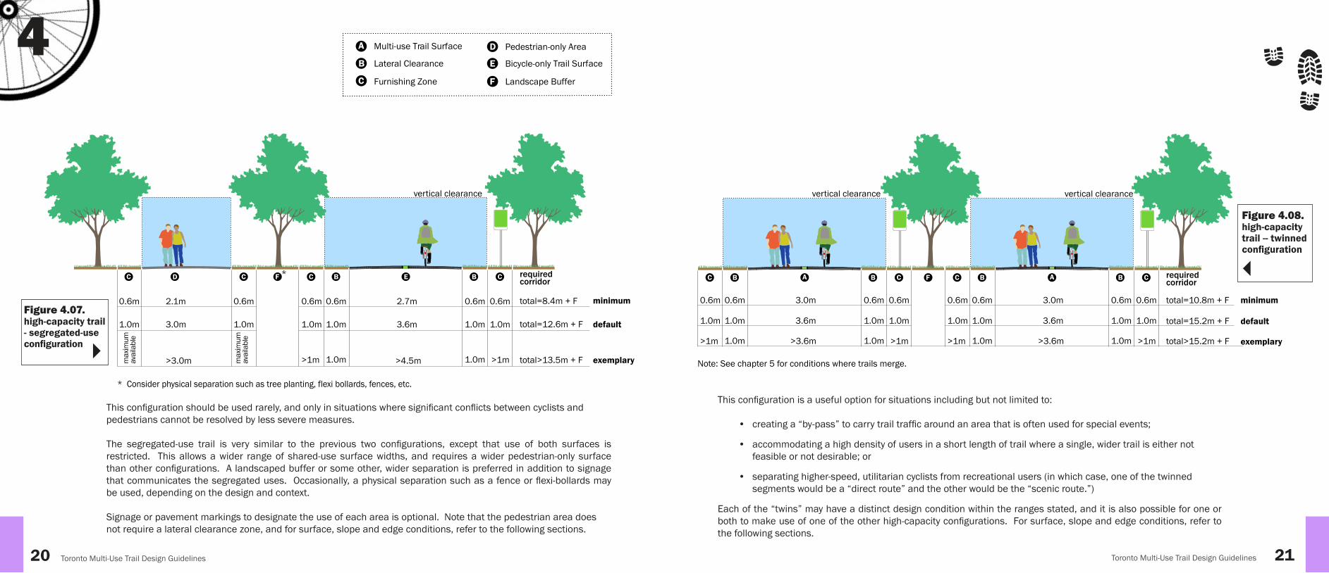
This coniguration is a useful option for situations including but not limited to:
• creating a “by-pass” to carry trail trafic around an area that is often used for special events;
• accommodating a high density of users in a short length of trail where a single, wider trail is either not feasible or not desirable; or
• separating higher-speed, utilitarian cyclists from recreational users (in which case, one of the twinned segments would be a “direct route” and the other would be the “scenic route.”)
Each of the “twins” may have a distinct design condition within the ranges stated, and it is also possible for one or both to make use of one of the other high-capacity conigurations. For surface, slope and edge conditions, refer to the following sections.
Figure4.08. high-capacity trail -- twinned coniguration
This coniguration should be used rarely, and only in situations where signiicant conlicts between cyclists and pedestrians cannot be resolved by less severe measures.
The segregated-use trail is very similar to the previous two conigurations, except that use of both surfaces is restricted. This allows a wider range of shared-use surface widths, and requires a wider pedestrian-only surface than other conigurations. A landscaped buffer or some other, wider separation is preferred in addition to signage that communicates the segregated uses. Occasionally, a physical separation such as a fence or lexi-bollards may be used, depending on the design and context.
Signage or pavement markings to designate the use of each area is optional. Note that the pedestrian area does not require a lateral clearance zone, and for surface, slope and edge conditions, refer to the following sections.
DC C F
0.6m 2.1m 0.6m total=8.4m + F
total=12.6m + F
total>13.5m + F
1.0m 3.0m
>3.0m
1.0m
max
imum
avai
labl
e
max
imum
avai
labl
e
EB BC C
0.6m 0.6m 2.7m 0.6m 0.6m
1.0m 1.0m 3.6m
>4.5m
1.0m
1.0m 1.0m
1.0m
>1m >1m
minimum
default
exemplary
* Consider physical separation such as tree planting, flexi bollards, fences, etc.
*
vertical clearance
required corridor
Figure4.07. high-capacity trail - segregated-use coniguration
4 A
B
C
Multi-use Trail Surface
Lateral Clearance
Furnishing Zone
D Pedestrian-only Area
E Bicycle-only Trail Surface
F Landscape Buffer

4
22 Toronto Multi-Use Trail Design Guidelines
Figure 3.08: Lateral clearances for rest stops or other trail amenity areas
1.0m min. Bench Clearance
1.0m min. Trail Clearance
Interpretation Signage
Area of SpecialInterest
Fence
Shade Tree
Toronto Multi-Use Trail Design Guidelines 23Figure 3.08: Lateral clearances for rest stops or other trail amenity areas
1.0m min. Bench Clearance
1.0m min. Trail Clearance
Interpretation Signage
Area of SpecialInterest
Fence
Shade Tree
LateralClearance
0.6m min.1.0m default
>1.0m not recommended
0.6m min.1.0m default
>1.0m recommended where possible
FurnishingZoneminimum size will accomodate vertical elements (signs, lights, trees); greater size permits wider range of elements
must remain unobstructed
Note: Where minimum clearances are not possible, mitigation measures such as warning signage, or trail calming are required. Greater clearances are not recommended except where they may be helpful to mitigate other conditions (such as tight turns).
4.3.1. Trail Width 4.4.1. Lateral Clearances
4.3.2. Trail Surface
4.3 Trail Width and Surface 4.4. Trail Edge Conditions
For every class of multi-use trail there is a default, minimum and exemplary width. In most cases there is no maximum.
Because design consistency is preferable to a frequently shifting design condition, trail designers should seek a balance between optimal trail conditions and site constraints. Widths below minimum should only be used for short distances where some physical constraint is present that cannot be overcome (bridge abutments, for example). In this situation, warning signs, and/or trail calming measures should be implemented.
The preferred surface for all multi-use or cyclist-only surfaces is asphalt. Any irm, durable, hard surface that conforms to accessibility requirements may be investigated during design. These may include concrete, pre-cast unit pavers, or specialty surfaces such as “TerraElast” (a proprietary, epoxy-based, porous pavement material). Granular surfaces, including those that are chemically stabilized are not recommended.
Pedestrian-only areas may also be any irm, durable, hard surface that conforms to accessibility requirements. Asphalt is generally preferred, however where the pedestrian-only area is near the multi-use trail, a distinct surface such as concrete, unit pavers or boardwalk is preferable to reinforce the pedestrian-only condition. Where the pedestrian-only area is a sidewalk or within a road right-of-way, concrete is the preferred surface. In some situations, granular surfaces (granite, limestone, or clay) may be acceptable, provided that they meet accessibility guidelines. Lateral clearances do not apply to pedestrian-only areas.
Separation strips may be any cane-detectable, visually contrasting surface. Metal “tactile walking surface indicator” strips may be most preferable, but are not necessarily feasible for long distances. Textured and/or coloured concrete, or unit pavers may be more suitable in many situations.
Surfaces for stairs, ramps and bridges are discussed in a later chapter.
Lateral clearances are areas to the side of the trail surface that improve safety conditions for trail users by providing space for avoiding collisions, running off the trail, or falling -- all without risk of colliding with any ixed object.
Lateral clearance areas are designed, constructed and maintained free from any obstruction. The surface is usually a different material but shall always be continuous with the trail surface. It should meet the same cross-slope requirements as the trail surface, and where it connects to trail-side amenities it shall also meet appropriate accessibility requirements.
The preferred lateral clearance for any class of multi-use trail is 1.0 metre; anything less than this should be provided with warning signage or other mitigation measures; wider lateral clearance areas are not recommended.
The minimum lateral clearance for any class of multi-use trail is 0.60 metres; in all cases, utilization of the minimum dimension should be justiied by the presence of some constraint that cannot be reasonably overcome, such as large trees or existing structures.
Where rest stops or other trail amenity areas are present, lateral clearances should include the cumulative width requirements for the trail, and for the rest stop, such as leg-space for a bench. Designers should consider providing a wider lateral clearance for a distance approaching the rest stop from each direction, and paving this area to allow trail users to slow down and pull off of the trail.
Shoulders are an extension of the travelled surface into the lateral clearance zone. Where they are used, a
solid white line should mark the boundary of the trail’s functional width, and all requirements for the lateral clearance zone must be met. Consideration may be given to using a cane-detectable, visually-contrasting surface to improve accessibility conditions.
Figure 4.10. dimensions of trail clearances
4.4.2. Furnishing ZoneThe minimum prescribed furnishing zone allows for vertical elements such as signs, lights and trees, while a wider zone allows for other kinds of furnishings, amenities, public art or other improvements. (Furnishings are discussed in a later chapter.) In restricted corridors where default or minimum dimensions are used, designers should consider occasional shifts of the trail alignment to permit both furnishing zones to be located on one side of the trail, which will permit a greater range of furnishing choices. Where continuous obstructions are present on one or both sides of the trail, this condition should be limited to approximately 20 metres or less.
1
2
3
4
5
6
7
Surface is usually cross-sloped in the same direction as adjacent grades, to 2% maximum; crowned paths may occasionally be appropriate
Asphalt pavement is usually 2 layers: coarse layer below, fine layer above
Compacted granular base may be single or multiple layers of a range of possible materials
Existing sub soils shall be scarified and compacted before placing the granular base
Adjacent surfaces shall be level with the pavement
The edge of the pavement shall be neatly tamped to 45 degrees
The granular base shall extend at least 200mm beyond the trail edge
All layers shall be parallel to the desired finished slopeNote:
width of trail(to top of tamped edge)
2
1
3
5
4
6
7
Figure 4.09. typical trail construction
4

44
24 Toronto Multi-Use Trail Design Guidelines
Figure 3.08: Lateral clearances for rest stops or other trail amenity areas
1.0m min. Bench Clearance
1.0m min. Trail Clearance
Interpretation Signage
Area of SpecialInterest
Fence
Shade Tree
Toronto Multi-Use Trail Design Guidelines 25Figure 3.08: Lateral clearances for rest stops or other trail amenity areas
1.0m min. Bench Clearance
1.0m min. Trail Clearance
Interpretation Signage
Area of SpecialInterest
Fence
Shade Tree
Figure 4.11. slopes or drop-offs parallel to trail
4.4.3. Continuous ObstructionsOccasionally, some continuous element will exist or be required to run parallel to the trail. These may include fences, guards, walls, hedges, or other elements. When the length of such an element exceeds approximately 20 metres, it is considered a continuous edge obstruction. This would include sections of trail on bridges or elevated structures.
It is recommended that continuous edge obstructions should be 2 metres from the trail. As a result, the furnishing zone would generally be considered to be the entire space between the lateral clearance and the obstruction. Items generally found within the furnishing zone may be located within this area.
Where the full 2 metre distance cannot be provided, some form of mitigation is recommended. Figure 4.12. shows the preferred approach. This is appropriate in natural areas where a minimal impact is desired, for example.
Trail calming measures or trail narrowing may be considered in addition to the choke feature and warning signs, but should not replace them.
In natural areas, new and existing trails may be constrained by vegetation that cannot be removed. If lateral clearances cannot be achieved in these situations, then appropriate mitigation measures should be implemented for both trail user safety and environmental protection.
Slopes and drop-offs that run parallel to a trail should be treated in the same way as a continuous edge obstruction, and kept 2 metres away from the trail. Where the slope exceeds 2:1 or 50%, and is higher than 0.6 metres, a guard should be provided. If the slope or drop-off must be less than 2.0 metres away, is in excess of 1:6 or 16.7%, and is higher than 0.6 metres, a guard should also be provided. The igure to the left outlines these requirements.
Where drop-offs or slopes provide views or some type of attraction, designers should consider treating that section of the trail with a high-capacity coniguration that features a pedestrian promenade, which does not require any separation from continuous obstructions (but does require separation from unprotected slopes over 0.6m).
Figure 4.12. example of clearance and mitigation for trails with edge obstruction
<2.0m
2.0m
2.0mpreferred
sepa
ratio
n st
rip
prom
enad
e
2.0m
0.6m or greater
>0.6m
>0.2m
No guard is recommended if: Slope is less than 2:1, or Height difference is less than 0.6 metres
Given a 2.0m or greater clearance from the slope,
Guard is recommended if: Slope is 2:1 or greater, and Height difference is 0.6 metres or greater
Given a 2.0m or greater clearance from the slope,
Guard is recommended if: Slope is 16.7% (1:6) and greater than 0.6 metres, or Drop off is greater than 0.2 metres in height
Given a clearance less than 2.0m from the slope,
Where slope or drop-off provides a view,consider promenade configuration
2.0m or greater <2.0m
Reflective hazard signsNecessary when clearance is <2m
Edge marking
ClearanceSurface may vary and can include
asphalt, concrete, lawn, or unit pavers. Flush transition required.
Choke featureAt termination of fence to beyond 2.0 metres from the trail
Warning Sign10 to 15 metres
before fence
The minimum height of guards shall be 1.37m
Gaps in guards shall be less than 0.1m or greater than 0.3m

44
26 Toronto Multi-Use Trail Design Guidelines
Figure 3.08: Lateral clearances for rest stops or other trail amenity areas
1.0m min. Bench Clearance
1.0m min. Trail Clearance
Interpretation Signage
Area of SpecialInterest
Fence
Shade Tree
Toronto Multi-Use Trail Design Guidelines 27Figure 3.08: Lateral clearances for rest stops or other trail amenity areas
1.0m min. Bench Clearance
1.0m min. Trail Clearance
Interpretation Signage
Area of SpecialInterest
Fence
Shade Tree
4.4.4. Curb-side ZoneWhere paths are adjacent to roadways, the furnishing zone may be treated differently, and is referred to as the curb-side zone. This area is used for loading and unloading, for the placement of signs and streetlights, and for street furnishings and tree plantings. In the winter it becomes a snow storage area.
The pedestrian clearway portion of the sidewalk is preferred to be 2.1 metres, while the minimum is considered to be 1.7 metres.
Where a sidewalk exists, the trail designer may provide the required separation strip between the trail and existing sidewalk. If the sidewalk is less than the preferred width, it can be widened, or space can be left for future widening. Building the separation strip next to an existing, narrower sidewalk may occasionally be unavoidable.
Where no sidewalk exists, the trail is preferably located to allow for a future sidewalk installation, which would require a minimum of 3.0 metres from the curb to the edge of the shared-use surface. Where no sidewalk is planned, the trail may be located 1.5 metres from the curb, which includes a 0.6 metre lateral clearance and a 0.9 metre curb-side zone. Smaller dimensions are discouraged, but may be considered on a case-by-case basis depending on site constraints.
Where a trail is planned in a restricted corridor, the corridor should be wide enough to accommodate the planned trail surface as well as appropriate lateral clearances and furnishing zones.
If the character of the proposed corridor includes steeper running slopes or frequent tight turns, additional widths should be sought to allow for the implementation of mitigating measures.
as exists(no change)
3.0mor greater
1.5mmin
WITH EXISTING SIDEWALK
NO EXISTING SIDEWALK :DEFAULT CONDITION
NO EXISTING SIDEWALK :CONSTRAINED SITES ONLY
Separation Strip:consider using additional width for future sidewalk expansion where applicable
where possible, leave 3.0 metres or greater for future sidewalk development
Trail Surface
Trail Surface
Trail Surface
4.5. Vertical ClearancesVertical clearances for all parts of all trail conigurations shall start at a default height of 3.0 metres. The minimum that should be considered is 2.5 metres.
This area should be kept free of all woody vegetation with branches or twigs over 0.02 metres, as well as any hanging elements such as lights in an underpass.
Where an overhead obstruction lower than 2.5 metres cannot be avoided, warning signs must be placed ahead of the obstruction. If it is a constructed element such as an underpass or gateway, a relective warning should be placed overhead, at the entrance to the obstruction.
DC C AB BC C
3.0 m default
vertical clearance
2.5 m minimum
For pedestrian-only areas, vertical clearance applies only to travelled surface
For multi-use or bicycle only surfaces, lateral clearance areas require full vertical clearance
Figure 4.14. vertical clearances
Figure 4.13. curb-side zones
Where one or both sides of the proposed trail corridor are to be fenced or blocked by some other continuous barrier, at least 2.0 metres should be provided on either side of the trail.
The preceding recommendations will provide only for a minimal total facility, even where default dimensions are used. Provision of a wider corridor wherever possible will allow for the development of better and more attractive trails and public spaces for the city.
A
B
C
Bicycle Trail Surface
Lateral Clearance
Furnishing Zone
D Pedestrian-only Area

44
28 Toronto Multi-Use Trail Design Guidelines
Figure 3.08: Lateral clearances for rest stops or other trail amenity areas
1.0m min. Bench Clearance
1.0m min. Trail Clearance
Interpretation Signage
Area of SpecialInterest
Fence
Shade Tree
Toronto Multi-Use Trail Design Guidelines 29Figure 3.08: Lateral clearances for rest stops or other trail amenity areas
1.0m min. Bench Clearance
1.0m min. Trail Clearance
Interpretation Signage
Area of SpecialInterest
Fence
Shade Tree
4.6. SlopesDue to accessibility requirements, running slopes on trails should be limited to 5%, and cross-slopes should be limited to 2% (including crowned conigurations).
Where a running slope greater than 5% cannot be avoided, designers should consult with stakeholders and use their best judgement to determine which of the following two options is preferred:
• design the sloped segment to be continuous with adjacent sections of trail, adding mitigation measures such as warning signage; or
• design the segment as a grade-separation, in accordance with the guidance set out in section 7.2 of this document. This would accommodate a wider range of possible strategies, such as stairs, ramps and/or switchbacks.
Lateral clearance areas should match the slope of the trail, and should also not exceed 2%. Furnishing zones that are intended to be occupied should also adhere to a 2% maximum. Any area outside of the lateral clearance, but within 2 metres of the shared-use surface should not exceed a downward slope of 16.7% (1:6), but may include a steeper uphill slope.
Stopping sight distance is the distance required for a trail user to decelerate to a full stop from a given speed.
The primary determinant for setting the minimum radius and related characteristics for curves in trail design is the stopping sight distance. Factors affecting this are the design user’s characteristics, design speed (which varies with slope) and friction. The design user in this case is a typical cyclist. Design speeds of 20 and 30 km/h are considered.
4.7. Curves
4.7.1. Stopping Sight Distances and Minimum Turning Radii
Figure 4.15. maximum cross-slopes
FurnishingZone
Lateral Clearance
2% max2% max*
* Slope of the lateral clearance area should match that of the trail surface
16.7% (1:6) max see Figure 4.11
The open sightline zone is a space on the inside portion of a curve—including at intersections—that is meant to be kept free of signiicant obstructions within the approximate eye-level range of trail users, or from approximately 0.6m to 2.0m height.
The open sightline zone is determined by the sight-stopping distance and the radius of the curve. It should allow a trail user to see obstacles or other users in the path ahead and stop completely before reaching them.
Signs, high-branching trees, light poles or other narrow, vertical elements are compatible with this space, as is low vegetation. Multi-stemmed or, low-branching trees, especially conifers, are not. Where vegetation can be cleared, the boundary of the area to be cleared should be marked as shown in igure 4.16, to ensure consistent maintenance practices.
In natural areas, clearing the open sightline zone may not always be appropriate, in which case warning signage and possibly trail calming measures should be introduced.
4.7.2. Open Sightline Zone
Figure 4.16. maintenance markers for curve clearances
ReflectiveMaterial
PressureTreated
Wood
1.0m
Install with equal spacing of approx. 6 meters between markers
From these, stopping sight distances and minimum turning radii are calculated as follows:
• At 20 km/h the stopping sight distance is 21 metres and the minimum turning radius is 10 metres
• At 30 km/h the stopping sight distance is 35 metres and the minimum turning radius is 20 metres
The preferred turning radius for all multi-use trails is 20 metres. Where running slopes are less than 3%, no mitigation is required.
Where space is restricted, a lower turning radius may be used, to a minimum of 10 metres. In these situations, warning signage and trail widening is required.
Where running slopes on or near the curve are more than 3%, warning signage and trail widening are required.
Where a running slope steeper than 5% cannot be avoided, a more detailed engineering analysis of curves should be undertaken. Wider radii or other mitigation measures can be implemented, as well as accessibility improvements such as warning signage and alternate routes.
On all curves, a wider lateral clearance shall be maintained, as shown on the illustrations that follow. In natural areas, marker posts are recommended at the limit of the clear space to assist with maintenance of the cleared area. Extensive clearing of all vegetation is discouraged in favour of occasional, selective clearing of woody vegetation over 0.6m height. Alternately, mitigation measures such as warning signage or trail calming may be considered.
This section does not apply to grade separations forming trail accesses, which are dealt with separately in section 7.2.
Superelevation (increased cross-slopes through curves) is sometimes used as a justiication to provide a tighter turning radius. Accessibility requirements restrict cross-slopes to 2%, thus eliminating superelevation as an option for multi-use trail design.
Figure 3.08: Lateral clearances for rest stops or other trail amenity areas
1.0m min. Bench Clearance
1.0m min. Trail Clearance
Interpretation Signage
Area of SpecialInterest
Fence
Shade Tree

44
30 Toronto Multi-Use Trail Design Guidelines
Figure 3.08: Lateral clearances for rest stops or other trail amenity areas
1.0m min. Bench Clearance
1.0m min. Trail Clearance
Interpretation Signage
Area of SpecialInterest
Fence
Shade Tree
Toronto Multi-Use Trail Design Guidelines 31Figure 3.08: Lateral clearances for rest stops or other trail amenity areas
1.0m min. Bench Clearance
1.0m min. Trail Clearance
Interpretation Signage
Area of SpecialInterest
Fence
Shade Tree
4.7.3. Typical Trail Curve Conigurations
20m Radius - 30 km/h speed - running slope = less than 3% - coefficient of friction = 0.25 - stopping sight distance of 35m
1m preferredlateral clearance
maintenancemarkers
sightline obstruction
edge of minimum open sightline zone 20m
7m4.2m
11m
Figure 3.12: Horizontal curves: 30 km/h bicycle design speed with no mitigation measures
Figure 4.17. horizontal curves:30 km/h bicycle design speed with no mitigation measures
10m Radius - 20 km/h speed - running slope = less than 3% - coefficient of friction = 0.25 - stopping sight distance of 21m
1m preferredlateral clearance
curvewidening
sightline obstruction
maintenancemarkers
3.4m 4.6m
10m
minimum : 30cmpreferred : 50cm
Figure 3.11: Horizontal curves: 20 km/h bicycle design speed with mitigation measures
edge of minimumopen sightline zone
BA
SHARP TURN
SHARP TURN
BA
Figure 4.18. horizontal curves: 20 km/h bicycle design speed with mitigation measures
Figure 4.19. horizontal curves: 30 km/h bicycle design speed with mitigation measures
20m Radius - 30 km/h speed - running slope = 3-5% - coefficient of friction = 0.25 - stopping sight distance of 39m
1m preferredlateral clearance
maintenancemarkers
opensightline
zone
sightline obstruction
20m
7m4.2m
11m
Figure 3.13: Horizontal curves: 30 km/h bicycle design speed with mitigation measures
curvewidening
minimum : 30cmpreferred : 50cm
A
AA
edge of minimum open sightline zone
The three igures on these pages show three different, typical scenarios for the design of curves in trails. The various combinations of trail geometry and supplemental measures are a toolkit that is capable of addressing most situations.
The more generous, wider curve shown below is intended as the irst option for designers. The designs on the facing page are intended to address situations where space is limited or where slopes are present, respectively.
The coniguration to the right and associated mitigation measures are designed to address running slopes from 3% to 5%. Steeper slopes should be subjected to a more detailed engineering analysis.
The coniguration to the right and associated mitigation measures are designed to address curve radii from 10m up to 20m. Curves tighter than 10m should be subjected to a more detailed engineering analysis.

44
32 Toronto Multi-Use Trail Design Guidelines
Figure 3.08: Lateral clearances for rest stops or other trail amenity areas
1.0m min. Bench Clearance
1.0m min. Trail Clearance
Interpretation Signage
Area of SpecialInterest
Fence
Shade Tree
Figure 3.08: Lateral clearances for rest stops or other trail amenity areas
1.0m min. Bench Clearance
1.0m min. Trail Clearance
Interpretation Signage
Area of SpecialInterest
Fence
Shade Tree
4.8. Existing, Non-conforming TrailsThroughout the City’s network of multi-use trails, examples can be found of facilities that in some substantial way do not conform to the recommendations of these guidelines. In some cases, the non-conforming qualities are a deining characteristic of those facilities. An example of this is the Kay Gardner Beltline Trail which is surfaced with “trap rock,” a sand material made from crushing and sieving granite. Although this material is not recommended in this guideline for use on any new multi-use trails, this guideline does not recommend that the Beltline be converted to some other surface. The trap rock surface is a deining characteristic of the trail. Any such changes should be reviewed through consultation with trail users and the local community.
Being a non-conforming facility may limit how this or any trail could be classiied. Even where several factors may suggest a more intensive development, these non-conforming qualities should be weighed against opposing factors. Where the situation of such a facility changes to such an extent that intensiication seems necessary due to user demand, an observed spike in user volumes, high seasonal or pedestrian uses, reported conlicts, or other reasons, it is strongly recommended that changes be carefully considered in consultation with stakeholders, users and the public.
Non-conforming “trap rock” surfacing material at the Kay Gardner Beltline Trail
A runner on the Humber Bay Bridge, as seen from the Humber Trail below

Figure 3.08: Lateral clearances for rest stops or other trail amenity areas
1.0m min. Bench Clearance
1.0m min. Trail Clearance
Interpretation Signage
Area of SpecialInterest
Fence
Shade Tree
Toronto Multi-Use Trail Design Guidelines 35Figure 3.08: Lateral clearances for rest stops or other trail amenity areas
1.0m min. Bench Clearance
1.0m min. Trail Clearance
Interpretation Signage
Area of SpecialInterest
Fence
Shade Tree
Toronto Multi-Use Trail Design Guidelines
This chapter is divided into three sections that relect the three broad categories of crossings that will be encountered: trail intersections, roadway crossings, and crossings of driveways and park roads.
Each section provides a range of useful scenarios and describes the various elements that make up a successful crossing: surface treatments, signage and signals, open sightline zones, etc.
In most cases, especially with regard to roadway crossings, these guidelines follow the guidance of the Ontario Trafic Manual Book 18 - Cycling Facilities.1 Where minor divergences are proposed, they are noted as such.
The primary objective of multi-use trail crossing design is to provide a safe and direct crossing for trail users. This chapter provides designers with detailed conigurations for intersections of trails with other trails, roadways, and driveways in a variety of situations, and provides criteria for choosing the most appropriate coniguration.
5 Trail Crossings
5.1. Trail IntersectionsWhen multi-use trails cross each other, the primary goal is to prevent collisions between users. This is achieved by designing trails with the appropriate alignments and sightlines, and by providing appropriate warnings to trail users when necessary.
A secondary goal is to ensure that trail users can navigate through the crossing easily. This is achieved by good trail design and reinforced by wayinding design and sign placement within the crossing coniguration.
All of these considerations are incorporated into the designs presented in this section.
Signalized crossing of Lawrence Avenue East on the Don Mills Trail
Trail crossings are excellent opportunities to provide amenities such as rest areas or infoboards. Typically, these should be located around the edge of the intersection, and should not interfere with the open sightline zones.
Trails should intersect each other at 90-degrees wherever possible.
As trail crossing angles move away from 90-degrees, sightlines and turning radii are affected. The result is either that these are compromised, or that open sightline areas take up signiicant amounts of space. Whenever possible, realigning pathways as close as possible to 90 degrees should be considered. In doing so, however, turning radii should be kept a safe distance away from the crossing, and should be designed in the manner described in the previous chapter.
The following igure provides a graphic description of the preferred, less preferred and discouraged crossing alignments.
Figure 5.01. alignments for trail crossings
1 http://www.otc.org/research/download-manuals/
90 60
<60
YES - BEST YES - LIMIT
NO YES
Figure 3.34: alignments for trail crossings

36 Toronto Multi-Use Trail Design Guidelines
Figure 3.08: Lateral clearances for rest stops or other trail amenity areas
1.0m min. Bench Clearance
1.0m min. Trail Clearance
Interpretation Signage
Area of SpecialInterest
Fence
Shade Tree
Toronto Multi-Use Trail Design Guidelines 37Figure 3.08: Lateral clearances for rest stops or other trail amenity areas
1.0m min. Bench Clearance
1.0m min. Trail Clearance
Interpretation Signage
Area of SpecialInterest
Fence
Shade Tree
10m min
open
sig
htlin
ezo
ne
15m pref.2
1
3
4
5
6
7
8
R=10m min*
Figure 5.02. crossing of two trails of similar width
5
R=10m min*
2
1
3
4
5
6
7
9
10
11
12m min** 3m
R=10m min*
8
2
1
3
4
5
6
7
Figure 5.03. crossing of two trails of different widths
Figure 5.04. T-intersection of two trails
Notes for igures 5.02, 5.03 and 5.04
For crossings of different classes or sizes of trails, the smaller facility should always be transitioned to match the larger, which should be considered the through-facility. Where there are alignment, grade or surfacing differences, the transition should occur on the smaller trail, in the area marked “transition area.”
The greater emphasis of warning signage should face the smaller facility, as the likelihood is greater of encountering faster or more trafic on the larger trail.
In most situations, following the guidance provided above, but removing the fourth leg of the crossing, will result in a good
design for a T-intersection. This is illustrated below.
The advice given previously with regard to emphasis of warning signage, can also be applied to the third-branch of a T-intersection.
Each of the three igures on the right shows a range of common elements or measures:
• The minimum open sightline zone at the crossing and the minimum lateral clearance of the linear trail are shown as a continuous light green colour.
• The preferred open sightline zone is shown as a dashed line at 45-degrees to the crossing trails.
• The centre line, broken elsewhere, is shown continuous in the vicinity of the crossing.
• Wayinding signs are shown for trail users approaching and leaving from each branch of the crossing.
• An enhanced surface is shown within the crossings --this is discretionary. This is typically used where added visibility or improved aesthetics are desirable. Various patterns or solid colours may be considered, but all must be non-slip and accessible.
Intersection of Finch Hydro Corridor Trail and a secondary trail in G Ross Lord Park - secondary trail has been aligned to intersect at 90-degrees
Multi-use trail
Unobstructed sightline area
Marking posts
Curves should be located beyond the unobstructed sightline area
Consider enhanced surface treatments (solid colour paint, textured and coloured asphalt, etc.)
2
1
4
5
3
*
11
10 Transition zone - same material as larger trail, no centre line unless present on smaller trail
Crossing approach - same width and material as larger trail, centre line present unless absent from larger trail
Where radius is increased above 10 metres, unobstructed sightline area should be adjusted to match
NOTE: the impressed surface is optional, but is recommended for high-use trails
Dashed line should not be present within intersection as defined by outer limit of the radius, except where enhanced surface treatment extends beyond that point
Wayfinding sign, installed beyond the unobstructed sightline area
Wayfinding and warning signs on common post, installed in advance of unobstructed sightline area
Smaller multi-use trail or other facility9
6
7
8

5
Figure 3.08: Lateral clearances for rest stops or other trail amenity areas
1.0m min. Bench Clearance
1.0m min. Trail Clearance
Interpretation Signage
Area of SpecialInterest
Fence
Shade Tree
Toronto Multi-Use Trail Design Guidelines 39Figure 3.08: Lateral clearances for rest stops or other trail amenity areas
1.0m min. Bench Clearance
1.0m min. Trail Clearance
Interpretation Signage
Area of SpecialInterest
Fence
Shade Tree
Toronto Multi-Use Trail Design Guidelines
lateral clearance
CD
A B
EA
A
F
B
wayfinding sign
wayfinding andwarning sings(optional, typical)
lateral clearance
Width as required for primary trail or betterWidth as required for primary trail or better (not necessarily equal to )Width as required for high-capacity trail (and at least as wide as or wider than or ) Merge distance determined by angle of approaching trail segments (10m minimum)Pave gore area to at least the point where lateral clearances intersectOpen sightline zone within gore to be at least 21 metres from merge point; signage and trees can be located within the area if they do not constitute a significant sightline obstruction
lateralclearance
A
B
C
D
E
F
Trail-trail crossing with enhanced surface treatment at Marie Curtis Park
T-intersection at the Gatineau Hydro Corridor Trail near Pharmacy Avenue
A park path merging with the Gatineau Hydro Corridor Trail near Thomson Memorial Park
Merging trails at Marilyn Bell Park
Figure 5.05. lateral clearance for two merging trails
Merging trails should generally be avoided, as described at the beginning of this section. Site constraints or other conditions--such as the beginning or ending of “twinned” trails, for example--are possible situations where an oblique T-intersection of two trails may be called for. The igure below illustrates how this should be conigured.
Note that the open sightline zone between diverging trails is a critical element towards reducing possible conlicts between trail users approaching the crossing from the two separate branches of the “twinned” trail.
As with previous conigurations, wayinding signage is provided for users entering or exiting the crossing by each branch.
Width as required for primary trail or betterWidth as required for primary trail or better (not necessarily equal to )Width as required for high-capacity trail (and at least as wide as or wider than or ) Merge distance determined by angle of approaching trail segments (10m minimum)Pave gore area to at least the point where lateral clearances intersectOpen sightline zone within gore to be at least 21 metres from merge point; signage and trees can be located within the area if they do not constitute a significant sightline obstruction
A
B
C
D
E
F
A
A B

40 Toronto Multi-Use Trail Design Guidelines
Figure 3.08: Lateral clearances for rest stops or other trail amenity areas
1.0m min. Bench Clearance
1.0m min. Trail Clearance
Interpretation Signage
Area of SpecialInterest
Fence
Shade Tree
Toronto Multi-Use Trail Design Guidelines 41Figure 3.08: Lateral clearances for rest stops or other trail amenity areas
1.0m min. Bench Clearance
1.0m min. Trail Clearance
Interpretation Signage
Area of SpecialInterest
Fence
Shade Tree
5.2.1 Pavement MarkingsPavement markings in roadway crossings serve primarily to provide the crossing with enhanced visibility for motorists.
The HTA does not provide speciic requirements for motorist behaviour in association with the various crossing markings that will be discussed here. Instead, motor vehicles are controlled by a separate system of signs, signals and markings. The markings shown in this section serve primarily to direct trail users, and as a secondary beneit provide a higher level of visibility for trail users crossing roadways.
5.0mmin.
*
2.0m min.*
OTM Book 18 recommends a minimum 2.5 metres widthfor the zebra strip in this crossride.
1.5m min.
1.5m min.
0.6m 0.6m 0.4m
zebra stripe
elephant’s feet0.4m 0.4m
Figure 5.06. mixed crossride
Figure 5.07. enhancement options for mixed cross-rides
Figure 5.08. combined crossride comprised of zebra stripes and elephant’s feet
5.2. Crossing Roads
min4.0m
0.4m
0.4m 0.4m
coloured pavement coating
textured &coloured pavement coating
Crossride is the term used for the markings that carry trail or cycling facilities across roadways and through intersections. There are four basic options
• mixed crossride
• combined crossride
• separated crossride
• asymmetrical separated crossride
The mixed crossride is the simplest option. It is comprised of “elephant’s feet” markings with symbols inside. All trail users share the space.
Provincial guidelines suggest assigning trail users space on the right side by positioning the symbols but not by use of a separation line. The symbols are discretionary, however, and it may be preferable in some situations to reduce visual clutter by using only the directional arrows.
Enhanced options for the mixed crossride are recommended for situations where additional visibility or aesthetic enhancement is desired. These are also suitable for non-roadway crossings, such as those that are discussed at the end of this chapter.
The combined crossride is comprised of “elephant’s feet” markings with “zebra stripe” markings inside. Pedestrians are intended to make use of the central area, and cyclists to use the outer parts.
It is more visible than the simple mixed crossride and will mostly be used at mid-block locations with low to moderate volumes of trail users. It may occasionally be appropriate for intersections where sidewalk and trail users mix, and where user volumes are low.
5
min4.0m
0.4m
0.4m 0.4m
coloured pavement coating
textured &coloured pavement coating
Where trails cross roads, road operations must continue to function as planned and in accordance with the Highway Trafic Act (HTA).1 All of the proposed crossing designs in this section should be applied only in consultation with qualiied staff.
Preferably, trail alignments are directed towards existing intersections where the crossing can be integrated into the existing operations. This is not always possible, and situations will occur where trails cross roads at mid-block locations. Both of these scenarios are included in this section.
Signalized crossing of Midland Avenue on the Finch Hydro Corridor Trail
1 http://www.e-laws.gov.on.ca/html/statutes/english/elaws_statutes_90h08_e.htm

5
42 Toronto Multi-Use Trail Design Guidelines
Figure 3.08: Lateral clearances for rest stops or other trail amenity areas
1.0m min. Bench Clearance
1.0m min. Trail Clearance
Interpretation Signage
Area of SpecialInterest
Fence
Shade Tree
Toronto Multi-Use Trail Design Guidelines 43Figure 3.08: Lateral clearances for rest stops or other trail amenity areas
1.0m min. Bench Clearance
1.0m min. Trail Clearance
Interpretation Signage
Area of SpecialInterest
Fence
Shade Tree
0.6m 0.6m
0.4m 0.4m 0.4m
2.5m min
0.3m
2.5m- 3.0m
zebra stripe
elephant’s feet
0.6m 0.6m
0.4m
2.5m min
2.5m-3.0m
0.3m
zebra stripeelephant’s feet
The separated crossride consists of “elephant’s feet” markings in the centre, surrounded by “zebra stripe” markings on both sides. In this coniguration, cyclists are intended to use the centre part, and pedestrians the outside.
This is intended for use at mid-block locations where trail user volumes are high, and usually where sidewalks are present. It is not used at intersections in Toronto.
Improved visibility is an added beneit, making this a suitable choice for signalized mid-block crossings of high-speed and high volume roadways.
The asymmetrical separated crossride is Toronto’s most widely-used crossing type and is appropriate for many signalized intersections, and some all way stop controlled intersections as well.
This crossride consists of “elephant’s feet” markings in the on one side and “zebra stripe” markings on the other. The zebra stripes and elephant’s feet should be aligned with the appropriate facility—typically the “zebra stripes” with the sidewalk and the “elephant’s feet” with the trail.
Many examples exist in Toronto (as seen in the photos in this section) where this crossride has been installed with bicycle symbols, however that coniguration will no longer be used.
Word markings will be seen on the trail in the approach to many of the crossing conigurations. The two examples at left are used in Toronto, and others may be possible depending on site-speciic needs. These should all be brief and clear, and should use short words. Where a universally accepted symbol exists, it should be used in place of word markings.
More information about these and other pavement markings is included in chapter 7.
Figure 5.11. pavement word markings
ROAD
AHEAD1.5m
1.2m
1.0m
1.0m SLOW1.2m
1.0m ROAD
AHEAD1.5m
1.2m
1.0m
1.0m SLOW1.2m
1.0m
Figure 5.09. separated crossride comprised of double zebra stripes and elephant’s feet
Figure 5.10. asymmetrical separated crossride comprised of zebra stripes and elephant’s feet
Trail crossings at roadway intersections are deined by whether the intersection is signalized or stop controlled, and further by the position of the trail and sidewalk (if present) relative to the edge of the roadway. The volume and speed of the roadway and the user volume of the trail may also inluence the choice of coniguration. Uncontrolled intersections are not treated here. Crossrides should not be included at uncontrolled intersections.
The irst three igures in this section are divided left-right to show how the trail crossing would be conigured when the sidewalk is next to the curb (left) or when a boulevard is present (right). The inal igure describes a roadway without a sidewalk, where these variations are not required.
5.2.2. Crossing Roads at IntersectionsEach coniguration illustrates the relative placements of different elements related to the crossing: crossrides, painted lines and symbols, signs, signals, and other elements that would be present.
The conigurations provided cross only one branch of the intersection. Trails occasionally cross two branches of intersections, as seen in the photo above. Design of such a two-stage crossing is, for the most part, a matter of applying the above conigurations to two adjacent branches of an intersection, while minding the relation to and crossing of adjacent pedestrian sidewalks.
5
Gatineau Hydro Corridor Trail crossing two branches of the McCowan Avenue (background) and St. Andrews Road (foreground) intersection using asymmetrical, separated crossrides

5
44 Toronto Multi-Use Trail Design Guidelines
Figure 3.08: Lateral clearances for rest stops or other trail amenity areas
1.0m min. Bench Clearance
1.0m min. Trail Clearance
Interpretation Signage
Area of SpecialInterest
Fence
Shade Tree
Toronto Multi-Use Trail Design Guidelines 45Figure 3.08: Lateral clearances for rest stops or other trail amenity areas
1.0m min. Bench Clearance
1.0m min. Trail Clearance
Interpretation Signage
Area of SpecialInterest
Fence
Shade Tree
ROADAHEAD
Figure 5.12.trail crossing at
intersection (signalized
example with
asymmetrical
separated crossride)
ROADAHEAD
ROADAHEAD
ROADAHEAD
1
1
6
2
3
4
4
4
4
5
boulevard
sidewalk
sidewalk
boul
evar
d
side
wal
k
side
wal
k
stop bar(typical)
BOULEVARD BETWEEN SIDEWALK AND CURB
SIDEWALK ADJACENTTO CURB
boulevard
multi-usetrail (typical)
pedestriansignal
(typical)
bicyclesignal
(typical)
1m
15m 5-10m
for diagrammatic purposes; roadways are not drawn accurately
offs
etva
ries
15m
m
in
0.6m m
in
CYCLISTS STOPHERE
ONRED
SIGNAL
CROSSING
SLOWWATCH FOR
TURNING VEHICLES
A
F
B
C
D
H
G
optio
nal
optio
nal
optio
nal
KEEPLEFT RIGHT
EKEEP
LEFTRIGHT
A
H
BCE
B CD
G
F
trail centre line shall be solid within 10m of stop bar at crossings
45
TRAIL CROSSING AT INTERSECTION(signalized example with ASYMMETRICAL SEPARATED crossride)
This coniguration consists of an asymmetrical separated crossride serving parallel multi-use trail and sidewalk facilities. It includes:
• bicycle signals (trail) and pedestrian signals (sidewalk)
• stop bars for trail users located behind the sidewalk
• solid centre line approaching the crossing
• warning and wayinding signage descriptions and placements
This is the most frequently used crossing coniguration for signalized intersections in Toronto.
This coniguration is appropriate for any signalized crossing where both trail and sidewalk are present.
5
2
1
4
5
3
6
Asymmetrical separated crossride (see Figure 5.10.)
Tactile walking surface indicator and flush curb, match width of crosswalk/crossride (typical)
Curb transition (typically 1.2 metres)
Pedestrian crossing configurations are drawn in accordance with Toronto Technical Standards drawings
Boulevard area forming part of trail crossing may be concrete, asphalt, or any other hard surface conforming to accessibility requirements; where sufficient space exists in the boulevard for a bicycle to stop, a waiting area should be provided, with the stop bar located near the curb (see Figure 5.16, upper right)
Optional warning text painted on trail (see Figure 5.11.)
NOTE: Where bicycle and other signals are positioned close together, they should be mounted on a single pole.
Signalized crossing of Sentinel Road on the Finch Hydro Corridor Trail with separated crossride

5
46 Toronto Multi-Use Trail Design Guidelines
Figure 3.08: Lateral clearances for rest stops or other trail amenity areas
1.0m min. Bench Clearance
1.0m min. Trail Clearance
Interpretation Signage
Area of SpecialInterest
Fence
Shade Tree
Toronto Multi-Use Trail Design Guidelines 47Figure 3.08: Lateral clearances for rest stops or other trail amenity areas
1.0m min. Bench Clearance
1.0m min. Trail Clearance
Interpretation Signage
Area of SpecialInterest
Fence
Shade Tree
ROADAHEAD
Figure 5.13.trail crossing at
intersection
(signalized
example with
combined
crossride) 0.6m m
in
ROADAHEAD
11
67
2
3
4
4
4
4
5
boulevard
sidewalk
sidewalk
boul
evar
d
side
wal
k
side
wal
k
stop bar (typical)
BOULEVARD BETWEEN SIDEWALK AND CURB
SIDEWALK ADJACENTTO CURB
boulevard
multi-usetrail (typical)
pedestriansignal
(typical)
bicyclesignal
(typical)
1m
15m
for diagrammatic purposes; roadways are not drawn accurately
offs
etva
ries
15m
m
in
5-10m
trail centre line shall be solid within10m of stop bar at crossings
CYCLISTS STOPHERE
ONRED
SIGNAL
CROSSING
SLOWWATCH FOR
TURNING VEHICLES
A
D
B
C
F
E
optio
nal
optio
nal
A
F
D
B C
E
ROADAHEAD
ROADAHEAD
47
TRAIL CROSSING AT INTERSECTION(signalized example with COMBINED crossride)
This coniguration consists of a combined crossride serving parallel multi-use trail and sidewalk facilities. It includes:
• bicycle signals (trail, discretionary) and pedestrian signals (sidewalk)
• stop bars for trail users located behind the sidewalk
• solid centre line approaching the crossing
• warning and wayinding signage descriptions and placements
5This coniguration is appropriate for a signalized crossing where both trail and sidewalk are present in very close proximity, and where user volumes are low on both the trail and the sidewalk. It may be more suitable for roads with lower speeds and volumes, or for secondary trail types.
The bicycle signal is considered discretionary because the trail users may be served by the pedestrian signal.
NOTE: Where bicycle and road signals are positioned close together, they should be mounted on a single pole.
2
1
4
5
3
6
7
Combined crossride (see Figure 5.08.)
Tactile walking surface indicator and flush curb, match width of crosswalk/crossride (typical)
Curb transition (typically 1.2 metres)
Pedestrian crossing configurations are drawn in accordance with Toronto Technical Standards drawings
Boulevard area forming part of trail crossing may be concrete, asphalt, or any other hard surface conforming to accessibility requirements; where sufficient space exists in the boulevard for a bicycle to stop, a waiting area should be provided, with the stop bar located near the curb (see Figure 5.16, upper right)
Optional warning text painted on trail (see Figure 5.11.)
Visually contrasting cane-detectable surface (such as tactile walking surface) where separation is less than 1.0 metre

5
48 Toronto Multi-Use Trail Design Guidelines
Figure 3.08: Lateral clearances for rest stops or other trail amenity areas
1.0m min. Bench Clearance
1.0m min. Trail Clearance
Interpretation Signage
Area of SpecialInterest
Fence
Shade Tree
Toronto Multi-Use Trail Design Guidelines 49Figure 3.08: Lateral clearances for rest stops or other trail amenity areas
1.0m min. Bench Clearance
1.0m min. Trail Clearance
Interpretation Signage
Area of SpecialInterest
Fence
Shade Tree
ROADAHEAD
ROADAHEAD
1
1
6
2
3
4
4
4
4
5
boulevard
sidewalk
sidewalk
boul
evar
d
side
wal
k
side
wal
k
BOULEVARD BETWEEN SIDEWALK AND CURB
boulevard
multi-usetrail (typical)
15m
for diagrammatic purposes; roadways are not drawn accurately
offs
etva
ries
15m
m
in
5-10m
CROSSING
SLOWWATCH FOR
TURNING VEHICLES
A
B
C
D
optio
nal
optio
nal
A
D
C
B
0.6m m
in
Figure 5.14.trail crossing at
intersection (all way
stop controlled
example with
asymmetrical
separated crossride)
ROADAHEAD
ROADAHEAD SIDEWALK ADJACENT
TO CURBtrail centre line shall be solid within 10m of stop bar at crossings
49
TRAIL CROSSING AT INTERSECTION(all way stop controlled example with ASYMMETRICAL SEPARATED crossride)
This coniguration consists of an asymmetrical separated crossride serving parallel multi-use trail and sidewalk facilities. It includes:
• “Yield” sign facing trail users
• NO stop bars for trail users
• solid centre line approaching the crossing
• warning and wayinding signage descriptions and placements
This coniguration is appropriate for any stop-controlled crossing where both trail and sidewalk are present.
2
1
4
5
3
6
Combined crossride (see Figure 5.08.)
Tactile walking surface indicator and flush curb, match width of crosswalk/crossride (typical)
Curb transition (typically 1.2 metres)
Pedestrian crossing configurations are drawn in accordance with Toronto Technical Standards drawings
For combined or mixed crossrides, the surface of the boulevard area within the crossing shouldbe concrete to match the pedestrian crossing
Optional warning text painted on trail (see Figure 5.11.)
5

5
50 Toronto Multi-Use Trail Design Guidelines
Figure 3.08: Lateral clearances for rest stops or other trail amenity areas
1.0m min. Bench Clearance
1.0m min. Trail Clearance
Interpretation Signage
Area of SpecialInterest
Fence
Shade Tree
Toronto Multi-Use Trail Design Guidelines 51Figure 3.08: Lateral clearances for rest stops or other trail amenity areas
1.0m min. Bench Clearance
1.0m min. Trail Clearance
Interpretation Signage
Area of SpecialInterest
Fence
Shade Tree
Figure 5.15.trail crossing at
intersection (all way
stop controlled
example with
mixed crossride) ROAD
AHEAD
5
1
1
4
3
6
boulevard
sidewalk
sidewalk
BOULEVARD BETWEEN SIDEWALK AND CURB
boulevard
multi-usetrail (typical)
15m
for diagrammatic purposes; roadways are not drawn accurately
15m
m
in
5-10m
trail centre line shall be solid within 10m of stop bar at crossings
CROSSING
SLOWWATCH FOR
TURNING VEHICLES
A
B
C
D
optio
nal
optio
nal
A
D
C
B
15m
min
B
2
0.6m m
inROADAHEAD
TRAIL CROSSING AT INTERSECTION(all way stop controlled example with MIXED crossride)
This coniguration consists of a mixed crossride serving a multi-use trail only. It includes:
• “Yield” sign facing trail users
• NO stop bars for trail users
• solid centre line approaching the crossing
• warning and wayinding signage descriptions and placements
This coniguration is appropriate for any stop-controlled crossing where a trail is present and a sidewalk is not.
5.2.3. Mid-Block Road CrossingsMid-block crossings may be uncontrolled or signalized. The Highway Trafic Act does not permit a stop-controlled mid-block crossing. This section begins with a discussion of the criteria for determining whether a crossing should be signalized or not, then presents two signalized crossing conigurations, along with three variations of an uncontrolled crossing.
The igure showing the signalized crossing coniguration is divided left-right to show the two possible conigurations. The upper and lower portions of each coniguration show how the trail crossing would be conigured when the sidewalk is next to the curb (lower) or when a boulevard is present (upper). The igure showing the uncontrolled conigurations presents each separately and completely.
Each coniguration illustrates the relative placements of different elements related to the crossing: crossrides, painted lines and symbols, signs, signals, and other elements that would be present.
All mid-block crossings will require implementation of a no-stopping zone adjacent the crossing to prevent physical or sightline obstructions.
SIGNALIZED OR UNSIGNALIZED?The criteria that are considered when deciding if a crossing should be signalized are daily trafic volume, posted speed limit, and road width. An uncontrolled crossing is suitable for roadways where these are less than 5,500 vehicles per day, 40km/h or less, and less than 4 lanes. Anything exceeding these limits should be signalized.
Roads exceeding 35,000 vehicles per day, 60 km/h and four lanes are typically not appropriate for an at-grade crossing. In rare cases however, a signalized crossing may be appropriate.
2
1
4
3
Mixed crossride (see Figures 5.06, 5.07)
Tactile walking surface indicator and flush curb, match width of crosswalk/crossride (typical)
Curb transition (typically 1.2 metres)
Optional warning text painted on trail (see Figure 5.11.)
5

5
52 Toronto Multi-Use Trail Design Guidelines
Figure 3.08: Lateral clearances for rest stops or other trail amenity areas
1.0m min. Bench Clearance
1.0m min. Trail Clearance
Interpretation Signage
Area of SpecialInterest
Fence
Shade Tree
Toronto Multi-Use Trail Design Guidelines 53Figure 3.08: Lateral clearances for rest stops or other trail amenity areas
1.0m min. Bench Clearance
1.0m min. Trail Clearance
Interpretation Signage
Area of SpecialInterest
Fence
Shade Tree
ROADAHEAD
ROADAHEAD
SLOW
BOUL
EVAR
D B
ETW
EEN
SI
DEW
ALK
AND
CUR
BSI
DEW
ALK
ADJA
CEN
TTO
CUR
B
multi-usetrail (typical)
bicyclesignal (typical)
pedestriansignal
(typical)
142
3
E
for diagrammatic purposes; roadways are not drawn accurately
15m
m
in
2.0m or greater
stop bartypical
(optional)
1m
6
15m 5-10m
5
7
multi-usetrail (typical)
15m
m
in
CYCLISTS STOPHERE
ONRED
SIGNAL
CROSSING
A
D
B
C
E YIELD TO PEDESTRIANS
A
E
D
B C B C
Requirements for both pedestrian and bicycle signals shall be determined based on site conditions.
0.6m m
in
ROADAHEAD
ROADAHEAD SIGNALIZED CROSSING
COMBINED CROSSRIDESIGNALIZED CROSSING
SEPARATED CROSSRIDE
Figure 5.16.mid-block crossing con�gurations
(signalized examples)
trail centre line shall be solid within 10m of stop bar at crossings
53
MID BLOCK TRAIL CROSSING(signalized example with SEPARATED crossride)
The coniguration on the left side of the facing page consists of a separated crossride serving multi-use trail and sidewalk facilities. It includes:
• bicycle signals (trail and sidewalk)
• stop bars for trail users located behind the sidewalk
• solid centre line approaching the crossing
• warning and wayinding signage descriptions and placements
This coniguration is appropriate for any signalized crossing where both trail and sidewalk are present. It is preferable for roadways with higher speeds and volumes, or for trails with higher volumes and/or a broad mix of user-types.
MID BLOCK TRAIL CROSSING(signalized example with COMBINED crossride)
The coniguration on the right side of the facing page consists of a combined crossride serving multi-use trail and sidewalk facilities. It includes:
• bicycle signals (trail and sidewalk)
• stop bars for trail users located beyond the sidewalk where the boulevard is wide enough for a cyclist to stop without obstructing the sidewalk, and behind the sidewalk in the lower part where no boulevard is present
• solid centre line approaching the crossing
• warning and wayinding signage descriptions and placements
This coniguration is appropriate for any signalized crossing where both trail and sidewalk are present. This coniguration should be the default approach for a signalized mid-block crossing.
5
NOTE: Where bicycle and road signals are positioned close together, they should be mounted on a single pole.
2
1
4
5
3
6
7
Symmetrical separated crossride (see Figure 5.09.). Note that an asymmetrical crossing is possible, where the pedestrian crossing is deleted from one side.
Tactile walking surface indicator and flush curb, match width of crosswalk/crossride (typical)
Curb transition (typically 1.2 metres)
Combined crossride (see Figure 5.08.)
Boulevard area forming part of trail crossing may be concrete, asphalt, or any other hard surface conforming to accessibility requirements
Optional warning text painted on trail (see Figure 5.11.)
Where sufficient space exists in the boulevard for a bicycle to stop, a waiting area should be provided, as shown, with the stop bar located near the curb

5
54 Toronto Multi-Use Trail Design Guidelines
Figure 3.08: Lateral clearances for rest stops or other trail amenity areas
1.0m min. Bench Clearance
1.0m min. Trail Clearance
Interpretation Signage
Area of SpecialInterest
Fence
Shade Tree
Toronto Multi-Use Trail Design Guidelines 55Figure 3.08: Lateral clearances for rest stops or other trail amenity areas
1.0m min. Bench Clearance
1.0m min. Trail Clearance
Interpretation Signage
Area of SpecialInterest
Fence
Shade Tree
NO MODIFICATIONS TO ROADWAY
“PINCH”CONFIGURATION
REFUGE ISLANDCONFIGURATION
2
1
3
Tactile walking surface indicator and flush curb, match width of trail (typical)
Curb transition (typically 1.2 metres)
Optional warning text painted on trail (see Figure 5.11.)
for diagrammatic purposes; roadways are not drawn accurately
15m min
C
B
BA
D
C
15m min
3m
0.15m
15m
15m
30m
15m min
5-10m
C
11m
C
EEEB
EB
0.6mmin
0.6mmin
2
1
side
wal
k
boul
evar
d
ROADAHEAD
SLOW
3
multi-usetrail (typical)
trail users’path of travel
1m
trail centre line shall be solid within10m of stop bar at crossings
guards/barricades(sightlines must not
be obstructed)
guards/barricadesCROSSING
SLOWWATCH FOR VEHICLES
A
C
B
D
E
optio
nal
optio
nal
optio
nal
“WAIT FOR GAP”
Figure 5.17.mid-block
crossing
con�gurations
(unsignalized
examples)
55
MID BLOCK TRAIL CROSSING(unsignalized examples)
Uncontrolled mid-block crossings are typically appropriate for the most amenable situations. These are typically small local roads with two lanes where volumes,
speeds and especially the crossing distances are low.
In the simplest example, (at left) no changes are made to the roadway.
Where the distance is greater, or some trafic calming is desired, a “pinch” may be appropriate (centre). This consists of narrowing the roadway in the vicinity of the crossing. The enhanced surfacing is discretionary, but greatly improves the visibility of the crossing.
Where distance is greater and speeds or volumes are elevated, a refuge island may be appropriate. This consists of an elevated island in the centre of the road.
The refuge island design necessitates that trail users face oncoming trafic before exiting. As such, the coniguration shown here must be used, and a mirror relection of it should be avoided. Trail designers should be conscious of the fact that a refuge island will add to the time required for crossing.
The refuge island design provides suficient space for waiting cyclists including tandems, recumbents and those with trailers. It is intended for riding through rather than dismounting, but is necessarily designed with narrow widths and tight turning radii, so additional trail calming measures can be an asset.
5
2
1
3
Tactile walking surface indicator and flush curb, match width of trail (typical)
Curb transition (typically 1.2 metres)
Optional warning text painted on trail (see Figure 5.11.)

5
56 Toronto Multi-Use Trail Design Guidelines
Figure 3.08: Lateral clearances for rest stops or other trail amenity areas
1.0m min. Bench Clearance
1.0m min. Trail Clearance
Interpretation Signage
Area of SpecialInterest
Fence
Shade Tree
Toronto Multi-Use Trail Design Guidelines 57Figure 3.08: Lateral clearances for rest stops or other trail amenity areas
1.0m min. Bench Clearance
1.0m min. Trail Clearance
Interpretation Signage
Area of SpecialInterest
Fence
Shade Tree
2
1
3
Tactile walking surface indicator and flush curb, match width of trail (typical)
Curb transition (typically 1.2 metres)
Optional warning text painted on trail (see Figure 5.11.)
ROADAHEAD
sidewalk
ramp
5-10m
15m
0.6m
m
infor diagrammatic purposes; roadways are not drawn accurately
A
B
D
C
multi-usetrail (typical)
trail centre line shall be solid within10m of stop bar at crossings
12
3
CROSSING
SLOWWATCH FOR VEHICLES
A
C
B
D
optio
nal
optio
nal
15m
5.2.4. Crossings at RampsCrossings of on- and off-ramps are conigured in a similar manner to mid-block crossings. The signiicant differences include (i) on-coming vehicles usually have poorer sightlines, so providing effective warning signs for the vehicles and good sightlines for waiting trail
Figure 5.18. unsignalized crossing coniguration of a trail and a roadway ramp
users is critical, and (ii) the sidewalk, if present will only be on one side of the trail--in this regard it is like a crossing at an intersection. The trail should be aligned so that the sidewalk and trail crossings are adjacent.
5.3. Park Roads and DrivewaysTrails running within road rights-of-way will also cross driveways. This presents a signiicant risk for faster trail users as motorists tend to expect slower trafic in the boulevard areas and frequently focus their attention on road trafic. Trail users also may not anticipate crossing motorists, especially at obscured or hidden entrances. It is for these reasons that roadways with numerous driveways are considered less suitable for multi-use trails in boulevards.
Where no alternative alignment exists, the following coniguration will help to reduce risks for trail users by
Figure 5.19. typical park road / driveway crossings:design options
road
driveway /park road
multi-use trail
B
A
C
textured or colouredsurface markingssolid line
withinten metres
15m
m
in15
m
min
15m min
C
A
B
SLOWWATCH FOR VEHICLES
CROSSING
All measures shall be considered optional. Where use is greater or visibility poorer, increasing levels of marking shall be used.
Trail surface shall be level throughout.
Bollards are discouraged.
NOTES:
enhancing visibility of crossings and improving sight lines.
In all options, it is preferable to balance the position of the trail between sightlines of motorists entering and exiting the driveway. The grade of the trail should not change through the crossing.
Prohibiting left-turn entrances and exits (for example by constructing a median in the roadway) is an additional measure that can improve conditions for trail users along roads with higher trafic volumes, or where many driveways are present.
5

Figure 3.08: Lateral clearances for rest stops or other trail amenity areas
1.0m min. Bench Clearance
1.0m min. Trail Clearance
Interpretation Signage
Area of SpecialInterest
Fence
Shade Tree
Toronto Multi-Use Trail Design Guidelines 59Figure 3.08: Lateral clearances for rest stops or other trail amenity areas
1.0m min. Bench Clearance
1.0m min. Trail Clearance
Interpretation Signage
Area of SpecialInterest
Fence
Shade Tree
Toronto Multi-Use Trail Design Guidelines
In Toronto, many of our trails exist in places that are not developed parkland or wide boulevards of local low-volume streets. Many of our trails are in ravines and river valleys, rail or hydro corridors, or in other spaces where special care in design is needed. This results in a character for our trails that is special, but also presents new sets of challenges for trail designers. This section identiies some of the common situations and challenges that arise, and provides guidance for addressing them.
6 Trails in Special Situations
6.1. Strategies for Multi-use Trail Development with Challenging or Constrained Site Conditions
6.1.1. Warning Signage
Implementing trails in areas of challenging or constrained site conditions should be avoided whenever possible. Where that is not possible the sections of trail may result that do not meet guidelines, or that may require special implementation measures to ensure the quality or safety of the built facility.
Where a section of trail must be installed that does not meet the guidelines, the following measures may be used. These situations should be minimized to the shortest possible length of trail, and appropriate mitigation measures should be provided, such as those described below.
Warning signage should be considered mandatory for all sections of a trail that do not meet the guidelines.
Warning signs should be located in advance of the area requiring warning, and should conform to standard
requirements for warning signs described in the Ontario Trafic Manual.1 The warning should specify the conditions that will be encountered. For additional information about signage, refer to chapter 7.
Section of the Finch Hydro Corridor Trail near G Ross Lord Park
Warning sign for a steep slope at the Finch Hydro Corridor Trail in G Ross Lord Park
1 http://www.otc.org/research/download-manuals/

6
60 Toronto Multi-Use Trail Design Guidelines
Figure 3.08: Lateral clearances for rest stops or other trail amenity areas
1.0m min. Bench Clearance
1.0m min. Trail Clearance
Interpretation Signage
Area of SpecialInterest
Fence
Shade Tree
Toronto Multi-Use Trail Design Guidelines 61Figure 3.08: Lateral clearances for rest stops or other trail amenity areas
1.0m min. Bench Clearance
1.0m min. Trail Clearance
Interpretation Signage
Area of SpecialInterest
Fence
Shade Tree
• Textured surfaces are an excellent way to slow down trail trafic, but must be non slip and accessible. Alternatives include detectable warning strips, imprinted asphalt or concrete, or unit pavers. Contrasting colour in combination with texture will improve trail user safety in these situations, but on its own does not represent a calming measure.
• Friction is a technique for slowing trafic where elements are located along the edge of a facility for the length where trail calming is desired. These should be kept outside of the minimum lateral clearance area, but should be in plain view. Flexi-bollards, fences, landscaping and other elements can be used.
• Gateway features and choke fences are more extreme measures that should be used with caution and should be located in a manner that allows the fastest trail users to see them and slow down, and should be implemented with signage requiring cyclists to slow, yield or dismount.
6.1.2. Trafic Calming for Trails
6.2.1. Trails on Steep Slopes
Several of the following measures may be used together or in combination, and should usually be combined with warning signs.
• Curves rather than straightaways will cause faster trail users to move more slowly; in most cases stopping sight distances should be maintained. In cases where stronger trail calming is desired, designers may reduce stopping sight distances and provide explicit warnings regarding restricted sight-lines. In these scenarios, additional measures should be considered for reinforcement.
• Smaller turning radii (below guideline recommendations) are an extension of adding curves, whereby the tighter radii cause faster trail users to slow down to negotiate the turn; these should always be provided with mitigation measures such as warning signage.
6.2. Constructing Trails in Challenging Site ConditionsThis section provides guidance for a selection of challenging situations that trail designers working in Toronto are likely to face. It is intended to be read in conjunction with the Toronto Multi-Use Trail Design Guidelines Construction Document Supplement, which includes further details related to implementation of many of this section’s recommendations.
10% 5%
2%
2%10
%
1
2
3
4
Locate curves away from slopes
Align trail diagonally across slope to achieve desired running slope (below 5%)
Figure 3.39: preferred alignment of trails on slopes
Cut-and-fill gradingWidened trail surface
upper slope
contour linelower slope
2
3
4
1
10% 5%
2%
2%10
%
1
2
3
4
Locate curves away from slopes
Align trail diagonally across slope to achieve desired running slope (below 5%)
Figure 3.39: preferred alignment of trails on slopes
Cut-and-fill gradingWidened trail surface
upper slope
contour linelower slope
2
3
4
1
10% 5%
2%
2%10
%
1
2
3
4
Locate curves away from slopes
Align trail diagonally across slope to achieve desired running slope (below 5%)
Figure 3.39: preferred alignment of trails on slopes
Cut-and-fill gradingWidened trail surface
upper slope
contour linelower slope
2
3
4
1
As trails strive to achieve universal accessibility, limiting running slopes will provide challenges for designers in many situations, especially in Toronto’s extensive ravine system. Avoiding steep slopes is the best strategy, however, this is not always practical or even desirable.
Where a trail must cross a steep slope, the following strategies may be considered:
• Trails should be aligned diagonally across slopes to achieve desired running slopes.
• Curves should be avoided (this includes switchbacks, except where they form park of a grade separation--see section 7.2). If a curve is required to align the trail with contours, the curve should be located above or below the slope. When a switchback is used for trail access, it is considered to be a distinct element which is discussed later in these guidelines.
• Trails should be installed by “bench-cut” grading, and should be cross-sloped to accommodate surface run off and prevent ponding.
• Sections of trail sloped more than 3% for a signiicant length should be provided with extra width, following similar guidelines to those for trail widening at curves, discussed earlier.
When site conditions make it impossible to establish a trail with accessible slopes, signage at trail entrances and published trail maps should indicate the non-accessible area, how long and how steep it is, and where the nearest accessible entrances and exits to the trail are found. Where possible, trail designers should seek to provide a parallel facility or detour that meets accessibility criteria.
Figure 6.01. preferred design for trails on slopes
Curved alignment of the Finch Hydro Corridor Trail near Sentinel Drive
A choke fence on the approach to a bridge/underpass on the Lower Don Trail near Taylor Creek Park
A steep slope at the Finch Hydro Corridor Trail in G Ross Lord Park
6

6
62 Toronto Multi-Use Trail Design Guidelines
Figure 3.08: Lateral clearances for rest stops or other trail amenity areas
1.0m min. Bench Clearance
1.0m min. Trail Clearance
Interpretation Signage
Area of SpecialInterest
Fence
Shade Tree
Toronto Multi-Use Trail Design Guidelines 63Figure 3.08: Lateral clearances for rest stops or other trail amenity areas
1.0m min. Bench Clearance
1.0m min. Trail Clearance
Interpretation Signage
Area of SpecialInterest
Fence
Shade Tree
6.2.2. Trails through Wet AreasTrails should not be routed through wetlands or seepage zones, or areas that have persistent or seasonally wet soils. They may be planned near these areas or in already impacted parts of such areas. Early Consultation with Toronto and Region Conservation Authority (TRCA) will help to ensure success.
Where such conditions cannot be avoided, special pathway construction methods may be appropriate.
The following general conigurations may be considered for such situations, depending on the exact nature of the site conditions. Variations on each of these designs are possible.
++++++
++++++
++++++
++++++
++++++
++++++
++++++
++++++
++++++
++++++
++++++
++++++
++++++
++++++
++++++
++++++
++++++
++++++
1
2
3
4
5
Trail surface - consider crowned trail for low-lying level areas with limited overland flows
Trail base - consider expanded depths, and use free-draining, compactible material such as Granular ‘O’
Geosynthetics for improved stability - extend beyond limit of trail base
Backfill with native soils and restore with dense plantings of bareroot or container plants and over seeding
Use existing adjacent plant communities as a guide for designing restoration
Figure 3.40: typical trail construction in wet soil areas
1
2
3
5
4
++++++
++++++
++++++
++++++
++++++
++++++
++++++
++++++
++++++
++++++
++++++
++++++
++++++
++++++
++++++
++++++
++++++
++++++
1
2
3
4
5
Trail surface - consider crowned trail for low-lying level areas with limited overland flows
Trail base - consider expanded depths, and use free-draining, compactible material such as Granular ‘O’
Geosynthetics for improved stability - extend beyond limit of trail base
Backfill with native soils and restore with dense plantings of bareroot or container plants and over seeding
Use existing adjacent plant communities as a guide for designing restoration
Figure 3.40: typical trail construction in wet soil areas
1
2
3
5
4
1
2
3
4
5
6
7
8
9
10
11
12
Trail width
Lateral clearance zone
Trail surface and paved shoulders (shoulders may be alternate material)
Trail base, built up in lifts (use free-draining, compactible materials such as Granular ‘O’)
Remove organic soils or at least uppermost vegetated layer and install geosynthetics for improved stability
Protect edges with rip-rap (shown) or armour stone. Conform to requirements for trails adjacent to slopes
Trail surface and lateral clearance areas (possibly two different materials)
Footings (requirements may vary)
Restoring work area below structure may not be possible; provide 50-75 mm size clear stone working surface
Guard where height is over 0.6 metres
Edge protection where height is below 0.6 metres
Adjacent undisturbed areas
Figure 3.41: raised and elevated trail configurations for wet soil areas
Raised Trail Elevated Trail
requires structural design; surfacingand structural systems may vary
3
4
5
7
9 12
6
1110
8
12 212 2
*
Figure 6.03. trail designconigurations for wet soil areas
The example shown below may be used in most areas where wet soils are present, seasonally, but standing water does not occur.
The designs shown to the right are appropriate where standing water is persistent or seasonally present. The example on the left will prevent overland lows, and should be constructed with culverts to preserve natural water movement as much as possible. Where erosion or wash-out risks are present, stronger edge protection is recommended. The example on the right allows surface lows to pass below.
Figure 6.02. typical trail construction in wet soil areas
6

64 Toronto Multi-Use Trail Design Guidelines
Figure 3.08: Lateral clearances for rest stops or other trail amenity areas
1.0m min. Bench Clearance
1.0m min. Trail Clearance
Interpretation Signage
Area of SpecialInterest
Fence
Shade Tree
Toronto Multi-Use Trail Design Guidelines 65Figure 3.08: Lateral clearances for rest stops or other trail amenity areas
1.0m min. Bench Clearance
1.0m min. Trail Clearance
Interpretation Signage
Area of SpecialInterest
Fence
Shade Tree
6.3. Trails through Natural AreasTrails provide an important recreational asset by facilitating access into natural areas. This is a beneit to trail users, but results in challenges for protecting the quality of the natural area. On one hand, the trail is a means to manage human impacts to the natural area by focusing them in appropriate places and on appropriate surfaces. On the other hand, trails interrupt the continuity of natural areas, provide pathways for invasive species to enter natural areas, bring wildlife into conlict with human activities, and ready access to natural areas for more adventurous trail users, off-leash dogs, and others.
Issues to be addressed by trail designers include regulations and approvals by authorities having jurisdiction, managing impacts of construction and operation, and constructing trails in adverse site conditions.
A natural area in the Highland Creek Trail near Colonel Danforth Park
6.3.1. Regulated Areas andApprovals by Authorities HavingJurisdiction
View of Highland Creek and trail from Morningside Avenue
6Preserving a suitable soil environment for tree roots below trails must be balanced against the need to prevent damages to the trail surface that may be caused by tree roots.
All trail construction or related excavations in the vicinity of trees must be reviewed and where appropriate approved by the Tree Protection and Plan Review section of the Urban Forestry branch of Parks, Forestry and Recreation. Any work completed within these areas must be done in conformance with City of Toronto Tree Protection Policy and Speciications for Construction near Trees.1
• Building trails over existing tree roots, where necessary may be accomplished by stripping only the top vegetated layer of soil by hand, and installing a minimum amount of granular base as a levelling course, followed by a single, heavy lift of asphalt pavement. This strategy may also include geo-
6.2.3. Trails in the Vicinity of Tree Roots
textile reinforcement over the stripped soil and has been used successfully in Toronto. Because of its elevated nature, care must be taken to ensure run-off is properly directed in the vicinity, and that the grading of trail edges transitions smoothly to meet existing grades.
• Preventing tree roots from growing beneath trails can be achieved by use of root barriers, many types of which are commercially available. Limestone should not be used as a means to prevent root growth due to the possibility of impacts to the ground water beyond the trail bed.
• Facilitating tree root growth below trails may be desirable in areas where tree planting space is restricted, such as within boulevard spaces. In such situations, soil cells are a suitable strategy, and are described in detail along with other strategies in Tree Planting Solutions in Hard Boulevard Surfaces – Best Practices Manual.2
1 http://www1.toronto.ca/city_of_toronto/parks_forestry__recreation/urban_forestry/iles/pdf/TreeProtSpecs.pdf2 http://www1.toronto.ca/city_of_toronto/parks_forestry__recreation/urban_forestry/iles/pdf/TreePlantingSolutions_
BestPracticesManual.pdf
In Toronto, natural areas are typically regulated by one or both of the Toronto and Region Conservation Authority (TRCA) and Ravine and Natural Feature Protection (RNFP)staff in the Urban Forestry branch of Toronto Parks, Forestry and Recreation. Each will be concerned with particular aspects of trail construction and operation and both must be consulted when planning any new trail or trail upgrades within natural areas, wet areas, seepages, or in proximity to slopes and watercourses.
TRCA and RNFP staff will advise about possible areas of concern, such as bird nesting habitats, isheries or the presence of protected species. Where concerns exist, TRCA and RNFP may assist with determining if additional requirements apply, and developing strategies to address those requirements.

66 Toronto Multi-Use Trail Design Guidelines
Figure 3.08: Lateral clearances for rest stops or other trail amenity areas
1.0m min. Bench Clearance
1.0m min. Trail Clearance
Interpretation Signage
Area of SpecialInterest
Fence
Shade Tree
Toronto Multi-Use Trail Design Guidelines 67Figure 3.08: Lateral clearances for rest stops or other trail amenity areas
1.0m min. Bench Clearance
1.0m min. Trail Clearance
Interpretation Signage
Area of SpecialInterest
Fence
Shade Tree
Environmentally Signiicant Areas and Areas of Natural and Scientiic Interest are speciic demarcated areas that in most cases are not compatible with multi-use trails. Where trails pass near these areas, mitigation and restoration measures should be anticipated and planned in consultation with the TRCA and RNFP staff. Any issues relating to areas of lood storage and conveyance or to lood hazards must be referred to the TRCA.
The most important aspects of managing construction and operation impacts are ensuring a minimal footprint for the trail and to prevent interfering with a site’s natural hydrology.
• Minimizing trail footprints: During construction, the footprint of activity should be constrained within the trail corridor (see chapter 4) on either side of the trail and this area should be demarcated by temporary fencing. Staging, and equipment or material storage areas must be located outside of the natural area. Construction activities should be followed by restoration immediately and should be scheduled to accommodate suitable planting and establishment times for restoration measures.
6
Invasive plant growth (dog-strangling vine) along Highland Creek Trail near Morningside Park
Erosion adjacent to Highland Creek Trail near Colonel Danforth Park Fence protecting natural area along the East Don Trail in at Charles Sauriol Conservation Area
Work within unobstructed sight line areas should be reduced to clearing of brush over 0.6 metres height and clearing of small branches below 2.5 metres height. This work must be done by hand, by qualiied workers, and in conformance with City of Toronto Tree Protection Policy and Speciications for Construction near Trees.
If the trail has been sized appropriately, impacts to the edge of the trail while in operation should not be signiicant. Where problems do arise from trail user behaviour, fencing will help reduce these impacts. Proper training of maintenance workers can prevent impacts from maintenance activities.
• Preventing disruption of water movement: Following the guidelines for trail slopes will help to ensure that impacts to water movement do not result from trail construction, by permitting natural overland lows.
Where a trail has steep slopes above or below it, overland lows can cause erosion, deposition and slope destabilization if not designed, constructed and maintained correctly. Each site will be different, however strategies including interception swales, erosion protection stone (rip-rap), stabilization plantings, and low-impact development can be used to mitigate potential erosion.
6.3.2. Managing Impacts ofTrail Construction and Operation
Concentrated lows, such as swales, ditches or seasonal streams should be bridged or conveyed within culverts.
Where concentrated lows run parallel to a pathway, they may constitute a continuous edge obstruction (see chapter 4).
• Preventing the spread of invasive plants is greatly helped by reducing the footprint of construction; additional measures during construction include avoiding importing soil, retaining existing vegetation in the lateral clearance areas and applying aggressive restoration practices that will not leave bare soils or mulch areas where invasive plants can gain a foothold. During operation of the trail, trail-side areas should be mowed as infrequently as possible, and preferably only cleared of woody vegetation.
• Preserving existing trees and vegetation is, again, partially helped by reducing the footprint of construction to the minimum area possible, and this preservation also supports preventing the spread of invasive plants; complying with Toronto’s Tree Protection Policy and Speciications for Construction near Trees is critical for both planning trails to avoid trees and for building trails near trees, as described earlier in this section.
• Reducing conlicts between wildlife and human activities includes a range of issues such as preventing disruptions to wildlife patterns, preventing risks to wildlife safety and preventing risks to human safety. These need to be assessed on a site-by-site basis, and may include choosing routes that avoid nesting areas, limiting artiicial lights in habitat corridors, providing snake basking areas away from the trail, and a wide range of other possibilities.

68 Toronto Multi-Use Trail Design Guidelines
Figure 3.08: Lateral clearances for rest stops or other trail amenity areas
1.0m min. Bench Clearance
1.0m min. Trail Clearance
Interpretation Signage
Area of SpecialInterest
Fence
Shade Tree
Toronto Multi-Use Trail Design Guidelines 69Figure 3.08: Lateral clearances for rest stops or other trail amenity areas
1.0m min. Bench Clearance
1.0m min. Trail Clearance
Interpretation Signage
Area of SpecialInterest
Fence
Shade Tree
6.4. Special RestrictionsToronto’s trails are occasionally constructed on land that is not owned by the City, or is encumbered by utilities or easements. Piggybacking a trail system within these networks can provide a highly-connected trail network for the City. In every one of these situations, it is a priority to identify and consult with the affected landowners or stakeholders early in the process and regularly as the design is developed. In these situations, it is both the functional constraints of the particular use encountered, AND the legal or bureaucratic requirements that will be determine how the trail is implemented.
In some of the cases discussed in this section, the land may be owned and managed by the City, but the use will create limitations. Again, the priority is to identify and consult with the affected stakeholders.
High-volume and high-speed roadways may have space for trails in the lands dedicated to them. Generally,
6.4.2. Trails in or adjacent to Rail Corridors
6.4.1. Trails Adjacent High-Volume or High-Speed Arterial Roadways
these are roadways with speeds of 60 km/h or more and four or more lanes of trafic. These types of roadways often do not have sidewalks, and a trail adjacent should be planned in a similar manner as a trail within a dedicated right-of-way.
The conlict between high-speed trafic and trail uses is best addressed by distance. Designers should try to achieve the maximum distance between the trail and the roadway. Aligning trails at the maximum distance from the roadway will also help to “future-proof” the trail against road expansions.
Where an appropriate distance cannot be achieved, guide rails and a physical separation such as a fence or landscaping are recommended.
Guidance provided earlier for roadway crossings may be applied to situations where the trail crosses a road that intersects a high-speed, high-volume road. In situations where an existing signalized crossing is present, it is possible for a trail to cross such a road.
Active and inactive rail corridors crisscross the entire City and present an opportunity for trail building. Both active and inactive rail lines present special challenges for trail development. Important resources include the Canadian Railway-Roadway Grade-Crossings Standards1
and a number of publications developed by the Rails to Trails Conservancy. These should be consulted for any trail design adjacent to an active or inactive railway.
Trails near active railways in Toronto will usually be separated physically by a chain link fence or a more signiicant barrier such as noise attenuation wall, even where the trail is on rail property. In the rare circumstance where this may not be the case, a distance of at least eight metres from the trail’s lateral
clearance to the centre of the nearest active track must be maintained, and some form of visual cue provided, such as landscaping or a less intensive fence design.
Trails in inactive or abandoned rail corridors may beneit from the relatively lat grades and compacted bases that are generally found in these locations however these sites should be investigated before planning for possible contamination issues. These are surmountable, but may add signiicant additional costs to the trail project.
RAIL CROSSINGSSituations calling for crossing of active railway lines will be infrequent, and will be subject to review by the rail operator, who may require additional measures such as signals and barriers. Where feasible, providing a grade-separated crossing is preferred to any at-grade solution.
The crossing coniguration shown at right is intended to provide general guidance only for designers and planners.
Crossing conigurations at rail lines should always be designed at 90-degrees for a minimum distance of 15 metres from the centreline of the track, or of the outer tracks where more than one is present.
RAIL
X-ING
1
2
34
5
1
2
3
4
5
66
8
9
7
8
9
7
Figure 3.37: trail crossing at active railway
15m min
8m min
Fence, where present, shall not extend within minimum lateral clearance area
Purpose-made rail crossing system to provide level, universal access across rail
Barrier and warning lights, where required
Warning and wayfinding signs on common post in advance of unobstructed sight line area
Where curves in trail alignment are near the rail crossing, provide an unobstructed sightline area of at least 25 metres from the near side of the crossing (measure to detectable warning strip)
Marking post to delineate lateral clearance
Detectable warning strip, full-width of trail on both sides and located 1 metre from barrier or fence
Rail
Centre-line of track
Figure 6.04. trail crossing at active railway
6
1 https://www.tc.gc.ca/eng/railsafety/grade-crossings-standards.htm
Martin Goodman Trail adjacent to Lakeshore Boulevard, near Ashbridges Bay The West Toronto Railpath,
adjacent to active rail lines

70 Toronto Multi-Use Trail Design Guidelines
Figure 3.08: Lateral clearances for rest stops or other trail amenity areas
1.0m min. Bench Clearance
1.0m min. Trail Clearance
Interpretation Signage
Area of SpecialInterest
Fence
Shade Tree
Toronto Multi-Use Trail Design Guidelines 71Figure 3.08: Lateral clearances for rest stops or other trail amenity areas
1.0m min. Bench Clearance
1.0m min. Trail Clearance
Interpretation Signage
Area of SpecialInterest
Fence
Shade Tree
When planning any trail, planners and designers should identify any existing utilities or utility easements as early as possible in the planning process. Measures required to construct a trail over such a utility will vary. Requirements may include daylighting the utility and backilling with unshrinkable ill or other special materials, or simply ensuring access for maintenance or upgrades.
Trails crossing private utilities typically are not signiicantly affected by the requirements of utility owners, because the affected area of the crossing is typically small. Trails running parallel to private utilities may share a corridor, but should typically be aligned parallel at a suficient distance that:
• capital costs related to special requirements do not become excessive, and
• repairs or improvements to the utility have less signiicant impacts on the trail condition and use
In natural areas, it may be desirable for the pathway and utility to share the same footprint. This will reduce potential impacts, but will also increase capital costs and result in a need to coordinate maintenance activities.
• Trails and ancillary elements must not be installed within 15 metres of tower foundations to prevent disruption during maintenance of the tower. In heavily constrained situations, HONI may consider a reduction of this distance.
As a general guideline, locating trails near the edges of hydro corridors preserves larger open spaces for other activities and reduces potential conlicts between trail uses and utility operations. This also may allow for utilization of shade and lighting assets present beyond the corridor boundary, or a simpliied rationalization for providing these within the corridor (i.e. trees planted at edges pose no risk to wires).
6.4.4. Trails over Pipelines and Other Private Utilities
6.4.3. Trails in Hydro-Electric Transmission CorridorsHydro-electric transmission corridors crisscross the city and provide opportunities for an extensive trail network. These lands are managed by a provincial crown corporation (Infrastructure Ontario) and operated by the utility, Hydro One Networks Incorporated (HONI). Consultation with both of these groups is critical for developing trails in these areas.
HONI will provide detailed input into designs to ensure that site-speciic concerns can be addressed. Their main concerns will be:
• Any grading associated with trail development must not interfere with natural drainage patterns of the transmission corridor.
• Height restrictions for light standards, plantings and other elements are typically dealt with on a case by case basis, and can depend upon the height and voltage of transmission lines.
• All trail access points must be designed to prevent vehicular access and should be clear of HONI maintenance access (see end of this chapter for access restriction measures).
• Anti-climbing barriers may be required on HONI structures along the length of the trail, as determined by HONI, to prevent unauthorized climbing of towers.
• Relective markers must be installed on all tower legs and at all tower locations along the route if the trail is to be used at night.
• HONI may be utilizing multi-use pathways on corridors from time to time for maintenance activities and will not accept responsibility for damages.
6.5. Multi-use Trails in Park Roads and Parking LotsWhere multi-use trails are routed on park roads, the results can fall between typical on-road cycling facilities and typical multi-use trails. In most cases, it would be preferable for the park road to function as a multi-use trail where motor-vehicles happen to be included among the permitted users. In these situations, a few basic rules can be applied:
• Motor vehicles should be limited to speeds of20 km/h or less.
• Regulatory and warning signs (stop, yield, etc.) should follow the requirements determined for motor vehicles.
• Wayinding signage for motor vehicles and trails should be distinct; the trail signage should follow the guidance in the next chapter.
• Ample symbol painting and signage should be provided to clearly communicate to motorists that trail users are present.
• Where curbs are present, the roadway should provide suficient width for the trail AND lateral clearances between the curbs; where no curbs are present and the roadway width only accommodates the paths-of-travel, the shoulders should meet the lateral clearance and shoulder requirements for trails.
• If a raised sidewalk is present, it should be considered a separate facility and conform to requirements for sidewalks, while the road continues to be considered a multi-use facility; if a sidewalk is present that is level with the road, then it should be included and should meet the requirements for a multi-use trail with an adjacent pedestrian-only area (one of the high-capacity conigurations).
6
The Finch Hydro Corridor Trail near McNicoll Avenue and Brimley Road
The Finch Hydro Corridor Trail crossing pipeline utilities near Sentinel Road

72 Toronto Multi-Use Trail Design Guidelines
Figure 3.08: Lateral clearances for rest stops or other trail amenity areas
1.0m min. Bench Clearance
1.0m min. Trail Clearance
Interpretation Signage
Area of SpecialInterest
Fence
Shade Tree
Toronto Multi-Use Trail Design Guidelines 73Figure 3.08: Lateral clearances for rest stops or other trail amenity areas
1.0m min. Bench Clearance
1.0m min. Trail Clearance
Interpretation Signage
Area of SpecialInterest
Fence
Shade Tree
5
5
7
1b
1b
13
12
14
1
2
3
5
4
5
6
1
51
7
8
9
1
11
10
2
1
1b
2
3
4
5
6
7
8
9
10
11
12
13
14
Warning sign: “WATCH FOR PEDESTRIANS AND AUTOMOBILES”
Warning sign: “WATCH FOR PEDESTRIANS”
Detectable warning strip
Pavement markings: with symbol painting at entrances and lines through the entire parking lot. Markings should be centred in aisle and match the width of adjacent trail sections. Demarcation lines and symbols should be provided. For high visibility and improved safety, consider full-colour painting.
Aisle to be 2-way and provided with extra width for improved visibility
Wayfinding sign
“NO MOTOR VEHICLES ON TRAIL” sign
Standard accessible parking space
Painted lateral clearance zone
Painted clearance zone beside parking space
Mixed crossride configuration. Consider treatment for improved visibility
Warning sign: “TRAIL X-ING AHEAD”
Staging and furnishing zone
Trail lateral clearance area. Use contrasting material
Curb ramp, not to extend into lateral clearance area
Trail Crossing Through Length of a Parking Lot Trail Crossing Through Width of a Parking Lot Trail Adjacent to a Parking Lot
Figure 3.38: trails through or adjacent to parking lots
5
5
7
1b
1b
13
12
14
1
2
3
5
4
5
6
1
51
7
8
9
1
11
10
2
1
1b
2
3
4
5
6
7
8
9
10
11
12
13
14
Warning sign: “WATCH FOR PEDESTRIANS AND AUTOMOBILES”
Warning sign: “WATCH FOR PEDESTRIANS”
Detectable warning strip
Pavement markings: with symbol painting at entrances and lines through the entire parking lot. Markings should be centred in aisle and match the width of adjacent trail sections. Demarcation lines and symbols should be provided. For high visibility and improved safety, consider full-colour painting.
Aisle to be 2-way and provided with extra width for improved visibility
Wayfinding sign
“NO MOTOR VEHICLES ON TRAIL” sign
Standard accessible parking space
Painted lateral clearance zone
Painted clearance zone beside parking space
Mixed crossride configuration. Consider treatment for improved visibility
Warning sign: “TRAIL X-ING AHEAD”
Staging and furnishing zone
Trail lateral clearance area. Use contrasting material
Curb ramp, not to extend into lateral clearance area
Trail Crossing Through Length of a Parking Lot Trail Crossing Through Width of a Parking Lot Trail Adjacent to a Parking Lot
Figure 3.38: trails through or adjacent to parking lots
Figure 6.05. trails through or adjacent to parking lots
6 • Road closures for seasonal or night-time restrictions should be communicated in signage and all other communications. Where it is possible to restrict only motor vehicles and not trail users, then care should be taken regarding the means of restriction (see chapter 7).
• Winter maintenance must be considered during design, for example by providing snow storage areas outside of cyclist operating space.
Park roads can also function as roadways with typical on-road cycling facilities and separate pedestrian facilities, where heavier trafic is present or sightlines are restricted. In these situations, designers should refer to guidelines for on-street facilities, including the entire range of possible conigurations from signed routes up to cycle tracks, and including contra-low bike lanes where one-way park roads are present.
For trails through or adjacent to parking lots there are a greater number of possible hazards: reversing cars, distracted drivers, crossing pedestrians, and loading and unloading activities. The following guidance is intended to result in trail designs that improve visibility of the trail and promote awareness between all different modes within the parking lot:
• Trails through parking lots should be avoided wherever possible.
• Where a trail must be routed through drive aisles, those aisles should be two-way, and should be provided with additional width, and extensive markings and signage where possible. Trail calming measures should be applied as well.
• Where a trail crosses through a parking lot, perpendicular to the drive aisles, the portion that crosses the drive aisle should be treated as a mixed crossride; any portion of this facility that passes between or beside parked automobiles shall require lateral clearance areas AND additional clearance space from the parked car to allow for opening doors and staging from the vehicle. This has the added advantage of promoting the inclusion of accessible spaces near the trail.
• Where a trail is routed along the edge of a parking lot, the trail’s lateral clearance must be kept free of signs, lights and other elements. Additional space should be provided for these and also for staging from vehicles.
• Winter maintenance must be considered during design, for example by providing snow storage areas outside of cyclist operating space.
Finch Hydro Corridor Trail adjacent to a parking lot in G Ross Lord Park

74 Toronto Multi-Use Trail Design Guidelines
Figure 3.08: Lateral clearances for rest stops or other trail amenity areas
1.0m min. Bench Clearance
1.0m min. Trail Clearance
Interpretation Signage
Area of SpecialInterest
Fence
Shade Tree
Toronto Multi-Use Trail Design Guidelines 75Figure 3.08: Lateral clearances for rest stops or other trail amenity areas
1.0m min. Bench Clearance
1.0m min. Trail Clearance
Interpretation Signage
Area of SpecialInterest
Fence
Shade Tree
2
1 4
5
3
Sidewalk (if present)
Boulevard (varies, if present)
Curb with transition
Tactile walking surface indicator
Roadway
NOTE: For general arrangement of crossings, refer to Chapter 5.
divided centre lineand widened trail
3 removable bollards[outer bollards optional]
adjust position of stop bar and sign
2
54
1
1.0m
1.5m min2.0m max
0.6m
3
2
3 54
1
default condition - no barrier
54
1.0mdivided centre lineand widened trail
3 flexi-bollards [outerbollards optional]0.6m
1.5m min2.0m max
adjust position of stop bar and sign
2
3
1
flexi-bollards (1.0m tall min.)
2
3 54
1
1.0m
1.0m
offset “P” gate
1.5m min2.0m max
illustrations are fordiagrammatic purposes
gates (discouraged)offset, 1.4m tall
bollards (discouraged) removable, 1.0m tall
6.6. Vehicular Access ControlTrail entrances near roadways may be mistaken as roadways by motorists, or wilfully accessed for short-cuts or other purposes. Controlling unauthorized access to trails by motor vehicles must be balanced against the need for emergency vehicle and maintenance access. While it can be dangerous and disruptive, the actual frequency of motor vehicles entering trails may be quite low, and may be largely a result of ignorance rather than bad intent.
Thoughtful trail design can help prevent unauthorized access by presenting a facility that is clearly a trail rather than a road. Strategies for this can include enhanced landscaping adjacent to the trail and bold designation
6
Figure 6.06. vehicular access control options
signage. In addition, trail calming measures such as gateway features or textured pavements can assist in controlling unwanted vehicles on trails.
Where controls beyond design improvements are considered, the default control should be no control or only signage. Where problems are reported, increasing levels of control should be implemented until the problems are reduced to an acceptable level. Signage, median islands and lexi-bollards are the preferred control measures, whereas bollards and P-gates are a last resort when all other methods have been proven unsuccessful, or in some cases, where they may be required by landowners.
Access to the Finch Hydro Corridor Trail at Silver Star Boulevard with motor vehicle restriction measures

Figure 3.08: Lateral clearances for rest stops or other trail amenity areas
1.0m min. Bench Clearance
1.0m min. Trail Clearance
Interpretation Signage
Area of SpecialInterest
Fence
Shade Tree
Toronto Multi-Use Trail Design Guidelines 77Figure 3.08: Lateral clearances for rest stops or other trail amenity areas
1.0m min. Bench Clearance
1.0m min. Trail Clearance
Interpretation Signage
Area of SpecialInterest
Fence
Shade Tree
Toronto Multi-Use Trail Design Guidelines
Many amenities beyond the trail surface are required in order to provide a functional facility and positive trail user experiences. These include signage and wayinding, grade separations, structures, lighting, site furnishings and a range of other elements.
7.1. Signage and WayindingThe following sections provide supplementary guidance to the earlier sections, with regard to signage, wayinding and related issues.
In all cases, sign panels and posts should be installed outside of lateral clearance areas, but not farther than 1.8 metres from the edge of the trail. Sign panels shall be installed with tops no higher than 2.4 metres and no lower than 1.8 metres. This balances visibility with reducing the risk of vandalism or theft.
Infoboards and any other signs with detailed information not intended to be read by trail users in motion should be placed away from the trail, with suficient room for trail users provided outside of the trail's lateral clearance areas, and separated by a visually-contrasting, cane-detectable surface. The height of the sign and its design should be optimized for comfortable reading. A height no higher than 1.7 metres and no lower than 1.0 metres is suggested.
To reduce visual clutter, it is preferable for signs to be attached to other elements such as lights if they are present, or for multiple sign panels to share a single post if they can it within the preferred height range, or for general information to be included on message boards rather than on trail signs. Stop and yield signs should not be installed with other signs.
7.1.1. Sign TypesREGULATORY SIGNSThese include signs such as yield or stop signs which communicate a regulation of some type to trail users. These signs are not to be confused with informational signs such as those that communicate bylaw information and which may form part of the wayinding system.
Regulatory signs shall be placed as close as possible to the point where the regulation is in effect.
WARNING SIGNS Warning signs serve to warn trail users about any abnormal or potentially hazardous conditions ahead such as steep slopes or sharp turns.
They should always identify the speciic condition being warned against.
Warning signs shall typically be placed a distance in advance of the condition identiied, except where the sign is placed as a marker on the potential hazard, such as the leading edge of a fence near the trail. The speciic location of sign placement will vary, but should give faster users suficient distance to stop. Typically this would be the sight stopping distance minus the distance that the sign can be read from. Warning signs include the typical black-on-yellow signs indicating permanent conditions as well as the black-on-orange signs indicating temporary conditions.
7 Design of Multi-Use Trail Elements and Amenities
Trailhead at the Don Mills Trail and Lawrence Avenue East

78 Toronto Multi-Use Trail Design Guidelines
Figure 3.08: Lateral clearances for rest stops or other trail amenity areas
1.0m min. Bench Clearance
1.0m min. Trail Clearance
Interpretation Signage
Area of SpecialInterest
Fence
Shade Tree
Toronto Multi-Use Trail Design Guidelines 79Figure 3.08: Lateral clearances for rest stops or other trail amenity areas
1.0m min. Bench Clearance
1.0m min. Trail Clearance
Interpretation Signage
Area of SpecialInterest
Fence
Shade Tree
0.6m min.1.0m pref.
0.6m min.1.0m pref.
1.8m
2.4m
2.4m max.
sign reading
area
- lateral clearance area- cane-detectable visually
contrasting surface
active trail surface
infoboard
lateral clearance area
sign panel envelope -ensure vegetation is
cleared to permit visibilityat least 10m away
active trail surface
Regulatory and warning sign designs and call numbers can be found in the Ontario Trafic Manual1. WAYFINDING SYSTEMThe wayinding system has six distinct signage types that work together to provide trail users with information that will assist them in navigating through the trail system. The information being communicated can be summarized as:
• conirmation that a facility is the desired trail;• selection of correct direction at intersections,
crossings, etc;
Figure 7.01.b. placement of infoboard
Figure 7.01.a. placement of signage
2 http://www1.toronto.ca/wps/portal/contentonly?vgnextoid=de73cc524a3d6410VgnVCM10000071d60f89RCRD&vgnextchannel=55d9dada600f0410VgnVCM10000071d60f89RCRD
• determination of distances travelled and distances to points ahead;
• identiication of major destinations and landmarks;• identiication of network connections to facilitate
changes in destination or routing;• identiication of levels of accessibility; and• rules-of-the-trail and etiquette
Individual sign types usually perform multiple functions. The placement of signs and the information presented in this document are a guide, however standards for trail signs shall conform to the Parks Wayinding Strategy2.
Decision SignsDecision signs are used to identify route options at any decision points along a trail (trail-trail crossings, trail-access intersections), and at access points to parks, streets, etc. Decision signs should include information about connecting trails, pedestrian or bicycle facilities, as well as identifying important destinations ahead. Decision signs should always make note of accessibility conditions, including a description of conditions to be encountered.Decision signs are to be located 5 to 10 metres before decision points.
Conirmation SignsConirmation signs are used to conirm to trail users what trail they are on, and to indicate distance to points ahead.
Conirmation signs are to be located 20 to 30 metres after decision points, as well as approximately every kilometer along a continuous trail where no other decision or information signs are present.
Access/Road Information SignsAccess/road information signs are used to identify the trail (by name and EMS location code, as applicable), to identify distance to the next trail exit, and to mention trail etiquette. In some cases, these signs may be superceded by an infoboard sign (below).
Access/road information signs are to be located 5 to 10 metres from the trail access road and be visible from any cycling or pedestrian facilities in the roadway.
Road Ahead SignRoad ahead signs are used to identify upcoming roadway crossings, to show a map of the immediate trail area, to identify distance to the next trail exit, and to mention trail etiquette. In some cases, these signs may be superseded by an Infoboard sign (below). Conirmation signs are to be located 15 to 20 metres ahead of the stopping area before crossing the road ahead.
7
1 http://www.otc.org/research/download-manuals/
A conirmation sign at the Finch Hydro Corridor Trail

80 Toronto Multi-Use Trail Design Guidelines
Figure 3.08: Lateral clearances for rest stops or other trail amenity areas
1.0m min. Bench Clearance
1.0m min. Trail Clearance
Interpretation Signage
Area of SpecialInterest
Fence
Shade Tree
Toronto Multi-Use Trail Design Guidelines 81Figure 3.08: Lateral clearances for rest stops or other trail amenity areas
1.0m min. Bench Clearance
1.0m min. Trail Clearance
Interpretation Signage
Area of SpecialInterest
Fence
Shade Tree
Confirmation
* regulatory signs not shown** excludes object marker signs
trail
nam
e
diag
ram
sym
bol
dest
inat
ion
dist
ance
s
trail
rule
s
stre
et a
ddre
ss
‘Yie
ld to
Ped
s’
road
nam
e
next
trai
l exi
t
trail
map
area
map
herit
age
haza
rd w
arni
ng
Decision
Access - Road
Road Ahead
Infoboard
Warning **
20-30m after Access - Trail intersection20-30m after Trail - Trail intersectionEvery km along the trail
5-10m before Access - Trail intersection5-10m before Trail - Trail intersection
5-10m from trail access at road (must be visible from roadway)
15-20m from road ahead
Trail - Trail Intersection Every 4 km along the trail
25m from hazard if grade is 2% or less40m from hazard if grade >2%
sign type* placement
information
C
D
A
R
I
H
Figure 4.02: Signage placement and content
InfoboardInfoboards are used to communicate a signiicant amount of wayinding and trail condition information to trail users. Some of this information is required by accessibility legislation, and must be presented in an accessible format. These items are:
• the length of the trail• the type of surface of which the trail is constructed• the average and the minimum trail width• the average and maximum running slope and cross
slope• the location of amenities, where provided• accessibility information
Figure 7.02. signage table: this table identiies the recommended placement and content for each of the sign types recommended
limited sightlines
road
trail
access
C
C
C
C
C
C
D
D D
DD
D
D
A
A
A
R
I
H
H
Figure 4.03: Signage placement plan
Figure 7.03. signage guide plan: this plan provides examples of appropriate placement for each sign type
7
In the context of Toronto's dense urban trails network, there are additional points that should be included:
• distance to the next trail exit/entrance in each direction, and to crossings with other trails (including accessibility information for exits or crossing facilities)
• where a trail entrance/exit is not fully accessible, this must be stated on the infoboard or another sign, along with information directing potential trail users to the nearest fully accessible entrance/exit
• presence or absence of lighting• seasonal closures or potential seasonal closures
Infoboards are also appropriate places to include maps, trail etiquette information, information about amenities (ie washrooms), natural or cultural attractions, and possibly community bulletins.
Infoboards should be located at all trail entry points and trail crossings. They should be installed partway along any stretch of trail that continues for more than four kilometres without the occurrence of any of the mentioned locations where an infoboard might be required.
Where a cluster of amenities is provided for trail users, an infoboard should be considered.
Miscellaneous SignsSpecial situations may call for unique signs to
indicate some particular feature or some unusual condition. These should follow the same principles of communication and appear to be of the same family as the preceding six sign types. An example of a miscellaneous sign is a trail etiquette sign.
Event signs or interpretive signs may also occur. They may follow a variety of possible formats, but should all adhere to principles of Universal Design, and should be located in accordance with these guidelines. Placement of miscellaneous signs will vary depending on what is being identiied by the sign.
Miscellaneous sign types should not be used to warn trail users of hazardous conditions. Instead, a Warning Sign should be used.

82 Toronto Multi-Use Trail Design Guidelines
Figure 3.08: Lateral clearances for rest stops or other trail amenity areas
1.0m min. Bench Clearance
1.0m min. Trail Clearance
Interpretation Signage
Area of SpecialInterest
Fence
Shade Tree
Toronto Multi-Use Trail Design Guidelines 83Figure 3.08: Lateral clearances for rest stops or other trail amenity areas
1.0m min. Bench Clearance
1.0m min. Trail Clearance
Interpretation Signage
Area of SpecialInterest
Fence
Shade Tree
DESIGNATION SYMBOLS Designation symbols typically communicate shared-use, or single use. At minimum, designation symbols should be placed at the beginning of a trail, the entrance to any stage of a crossing, and shortly after a crossing. They can also be placed at intervals along the length of a trail to remind trail users to keep to the right. Directional arrows are used in conjunction with designation symbols in most situations except for at crossings.
CROSS-HATCHES Cross-hatches may be used to indicate waiting areas or to demarcate areas outside of the trail but on a common surface.
SOLID COLOURED AREASEarlier in this report, solid coloured areas and imprinted and coloured areas have been recommended for enhancing visibility or for providing trail calming at crossings and some other situations. These should generally be provided in a contrasting colour, but usually not white or yellow as symbols or lines in these colours may need to overlay them.
7.2. Grade Separations and Structures7.2.1. Access Stairs and Ramps (including switchbacks)Access stairs and ramps are important parts of trail systems. They are necessary for providing access to trails from adjacent areas at higher or lower elevations, and in some cases for connecting two separate trail facilities. Access stairs and ramps should be treated differently from linear trail facilities, and should not interrupt continuous trail alignments.
A few general guidelines can be applied:
• It is broadly desirable to maximize the number of access points to and from trails; priority should be given to providing accesses that are most convenient for the greatest number of people; a second priority may be given to locations that are considered “quick wins.”
• Providing universal accesses that can be navigated by users with a wide range of abilities is very
important, and all new or upgraded trail accesses should seek to satisfy at least the most current legislated accessibility requirements; care should be taken that the trail being accessed is also accessible.
• Ramps should be designed to meet and exceed Ontario Building Code1 and the Integrated Accessibility Standards Regulation Guidelines2 where possible. These include all of the dimensional requirements for stairs and ramps as well as requirements for surfaces, guards, handrails and most other components.
• Where a switchback is desired, it should be designed to conform with the requirements for ramps that are noted above. Avoid design features that encourage or facilitate fast cycling (long, straight runs, greater widths) because the turning radii used for switchbacks are not suitable for such a use.
1 http://www.mah.gov.on.ca/Page7393.aspx2 http://www.mcss.gov.on.ca/documents/en/mcss/accessibility/DOPS%20Guidelines%20
(short)%20FINAL%20April%202014%20EN-s.pdf
7All new trails should be provided with centre lines. The default approach should be a broken green line. Solid lines may be used on the approaches to crossing and curves or in other areas to reinforce the intention that trail users should keep to the right. Other colours of lines, solid or dashed, and even combinations of lines of different colours may be utilized as part of a design theme for trails. The Lake Ontario waterfront trail uses parallel, solid blue and green lines, for example.
STOP BARSStop bars should be placed adjacent to any stop signs or at signalized intersections along the trail, and should be white. See chapter 5 for additional info.
WORD MARKINGSWord markings may be used to warn trail users about conditions ahead, reinforcing warning signs, but not replacing them. They should be placed between the warning sign and the condition being identiied to reinforce the warning. Word markings should be composed as they would be on a page of text, with subsequent lines placed to be visible at once. The colour should be white. See chapter 5 for their use near crossings.
SYMBOLSSymbols are preferable to word markings where possible. The colour should be white.
DIRECTIONAL ARROWSThese may be placed at intersections or near tight curves to help prevent conlicts by reminding trail users of their correct positions. They may also be used at trail entrances or along the trail. The colour should be white.
7.1.2. Pavement Markings
Access stairs with channels for carrying bicycles, at Mallaby Park
A ramp connecting the Eglinton West Trail to an overpass
Creative use of pavement markings to indicate the path of travel through a refuge island at the intersection of the Lower Don Trail and Pottery Road

84 Toronto Multi-Use Trail Design Guidelines
Figure 3.08: Lateral clearances for rest stops or other trail amenity areas
1.0m min. Bench Clearance
1.0m min. Trail Clearance
Interpretation Signage
Area of SpecialInterest
Fence
Shade Tree
Toronto Multi-Use Trail Design Guidelines 85Figure 3.08: Lateral clearances for rest stops or other trail amenity areas
1.0m min. Bench Clearance
1.0m min. Trail Clearance
Interpretation Signage
Area of SpecialInterest
Fence
Shade Tree
7.2.2. BridgesIn this section, bridges are discussed as a continuous component of a linear pathway facility. Where a bridge is accessed via stairs or ramps as discussed above, it becomes part of the grade separation and may be governed by those requirements instead. All bridges will require detailed structural design, and will normally require consultation with the authority responsible for the area being crossed (conservation or road authority, for example). For initial planning, the following guidelines apply:
• The preferred width of the bridge (between the guards) is the trail width plus lateral clearance areas (refer to chapter 4).
7• Both stairs and ramps can be installed as in-ground
or elevated structures. Elevated structures, though more costly are preferable (especially for stairs) due to a somewhat reduced construction impact in natural areas, longer service life, and the ability to maintain existing drainage patterns.
• Generally, a clear width of two metres between handrails is appropriate as it permits two users to pass in opposite directions and does not trigger a code requirement for a centre handrail.
• Because these facilities are not considered part of the linear trail, they are not usually widened to accommodate heavier use (although this can be considered); instead, extra space should be provided at landings to allow users to rest, to enjoy the view or to wait for the way ahead to become clear; this also requires clear sight lines from one landing to the next, or preferably from the top to the bottom of the entire stair or ramp.
• At the top and bottom of stairs and ramps, there should be space for trail users to set up or orient themselves; this should be a minimum of three or preferably ive metres from the edge of the trail;
coordinating amenities such as seating or water bottle illers at these locations is recommended.
• Wayinding sign placement should include, at minimum, clear decision or direction signs at the top and bottom of all stairs (for trail users entering or exiting at these locations); provision of map and information signs and accessibility information is recommended on the side of the facility that constitutes an entrance to the trail system.
• It is recommended that stairs be provided with channels for bicycles and other wheeled devices such as strollers. These should be constructed from visually-contrasting materials, and should not obstruct pedestrian use of the hand grab on either side. These should be on both sides, if feasible, and should be approximately 0.2 metres wide. A raised lip (approximately 0.05m) can help to keep wheels on the channel and make it more visible. Channels should connect smoothly with any landings.
• Stair and ramp combinations may also be considered to provide choices for trail users and a combination of access and convenience.
• A minimum guard height of 1.37 metres is required on both sides; some circumstances may call for a taller guard; the guard should be non-climbable.
• Where a bridge’s width is less than the recommended width, the guard should be provided with a non-metallic (wood or plastic) guide rail; taller guards should be considered; the terminations of guards at either end of the bridge should be lared out beyond the lateral clearance area, and warning signage should be provided; trail calming measures are also recommended.
• The preferred surface on a bridge is bare, non-slip concrete and weathering steel decks are also acceptable and frequently used. The latter is especially useful where the bridge is narrower than the path. The premium surface is asphalt pavement over a concrete deck because it provides continuity with the trail surface. Wood decking has also been used. It is often considered appropriate for natural areas, but care must be taken to use a durable, chemical-free, non-slip wood decking product, aligned perpendicular to the direction of travel.
• All horizontal requirements for trails may be applied to bridges.
A bridge on the Finch Hydro Corridor Trail
Gatineau Hydro Corridor Trail bridging over Highland Creek near Thompson Memorial Park View of the Humber Bridge connecting the Martin Goodman Trail over the mouth of the Humber River

86 Toronto Multi-Use Trail Design Guidelines
Figure 3.08: Lateral clearances for rest stops or other trail amenity areas
1.0m min. Bench Clearance
1.0m min. Trail Clearance
Interpretation Signage
Area of SpecialInterest
Fence
Shade Tree
Toronto Multi-Use Trail Design Guidelines 87Figure 3.08: Lateral clearances for rest stops or other trail amenity areas
1.0m min. Bench Clearance
1.0m min. Trail Clearance
Interpretation Signage
Area of SpecialInterest
Fence
Shade Tree
In this section, as with bridges, tunnels are discussed as a continuous component of a linear pathway facility. Where a tunnel is accessed via stairs or ramps, it becomes part of the grade separation and may be governed by those requirements instead. All tunnels will require detailed structural design. For initial planning, the following guidelines apply:
• A tunnel should be the shortest length possible, with no curves or bends.
• The preferred width of the tunnel is the trail width plus lateral clearance areas (refer to chapter 4).
• Reducing the slope of a tunnel approach improves safety for trail users and maximizes daylight entering the tunnel (refer to chapter 4).
• A tunnel should meet the same overhead clearance requirements as trails.
• Where a tunnel’s width is less than the recommended width, the walls should be provided with non-metallic (wood or plastic) guide rails; the terminations of walls at either end should be lared out beyond the lateral clearance area (this may be done with a fence or
7.3. LightingLighting trails can signiicantly increase the utility of a trail by extending the hours where trail users will be comfortable on a trail. Every proposed new or upgraded trail should be considered independently and in consultation with stakeholders, before a decision is made to light it.
Lighting is recommended for multi-use trails, except where lighting would impact sensitive wildlife activities, invite trail users into dangerous situations, or where lighting would conlict with special requirements (in hydro corridors, for example). Excluding lighting on the grounds of potential nuisances is not recommended, as nuisances may be discouraged by other means.
Where lighting is not included, trail designers should consider lighting the entrances and exits and any intersections, if this can be done without creating the impacts described above. A trail should not be only partially lit between access points, as this can create hazardous situations for trail users expecting a trail to be fully lit. In other words, if part of a trail cannot be lit, the rest of the trail should not be lit. This does not apply to lighting in tunnels or underpasses.
The following points should be considered:
• Pole-and-arm mountings are preferred over post-top styles, and bollard-style lights should not be used because they are easily vandalized.
• Light poles must be located outside of lateral clearance areas, and consistently on one side of the trail only.
• Luminaires should be mounted so that their inished height is no lower than 4.5 metres above the trail surface (this is primarily to prevent vandalism, but also results in luminaires that are outside of the vertical clearance areas).
7 guard, and warning signage should be provided; trail calming measures are also recommended.
• The trail surface is preferably carried through the tunnel uninterrupted.
• Sightlines should allow for clear surveillance of the entire tunnel from one end to the other, and care should be given to preventing hiding spots or ambush points; lighting should be provided where possible.
• For drainage, a high point is preferably located in the middle of a tunnel, and the trail surface is crowned, ensuring any water will run out at the edges; the ground adjacent to the openings of the tunnel should be graded to provide positive drainage away from the entrance. Drain inlets or catch basins are preferably outside of the tunnel and away from the trail.
• A gutter or fence should be installed above the opening of the tunnel to divert runoff or other debris from falling on the trail.
• Luminaires should be a full-cutoff design, providing appropriate illumination levels, with minimal spill of light off of the trail surface. (Refer to OTM18.)
• Given the preceding requirements, light posts will usually be spaced at approximately 25 metres apart.
• Lamps should be energy eficient, long-lasting and provide good colour rendering. LED lamps should be considered for new lighting, but may not be appropriate for retroitting existing trail lights if the existing equipment and/or infrastructure is not compatible.
• Consider energy-saving approaches such as timers, motion sensors, and user-activated lights.
• Locate electrical cabinets where they can be easily accessed by maintenance vehicles; ensure that access doors face the trail at a distance where neither the doors nor an operator would encroach into the lateral clearance area of the trail.
Professional lighting and electrical design is required for trail lighting, and certiication by the Electrical Safety Authority (ESA) is also necessary.
Where trails are not lit, it is recommended to provide this information on signs or infoboards at trail entrances.
7.4. Resting and Viewing AreasResting and viewing areas are similar types of areas, differentiated only by a subtle difference in use. Resting areas are designed and situated simply to provide a resting space for trail users, whereas viewing areas are located strategically with regard to some feature, and designed to accommodate that activity. A few simple guidelines and suggestions can help to ensure that these elements function well.
7.2.3. Tunnels and Underpasses
The Rainbow Tunnel at the East Don Trail
Light standards along Martin Goodman Trail waterfront promenade at Marilyn Bell Park

88 Toronto Multi-Use Trail Design Guidelines
Figure 3.08: Lateral clearances for rest stops or other trail amenity areas
1.0m min. Bench Clearance
1.0m min. Trail Clearance
Interpretation Signage
Area of SpecialInterest
Fence
Shade Tree
Toronto Multi-Use Trail Design Guidelines 89Figure 3.08: Lateral clearances for rest stops or other trail amenity areas
1.0m min. Bench Clearance
1.0m min. Trail Clearance
Interpretation Signage
Area of SpecialInterest
Fence
Shade Tree
Resting areas should…• be located on both sides of the trail, visible from
each other. This is so trail users moving on either direction can enter resting areas without crossing the trails.
Viewing areas should…• be provided with caution signs in both directions, as
trail users will cross the trail to access the viewing area;
• be generally planned to optimize and preserve sightlines to the feature;
• be provided with a portion of seating arranged to view the feature; and
• be provided with informational or interpretational signage.
Resting and viewing areas are excellent opportunities for provision of additional or enhanced trail amenities.
7.5. TrailheadsTrailheads can be developed as resting or viewing areas that happen to be located at trail entrances. As they additionally function as staging and meeting areas, a few additional guidelines apply:
• Additional space should be provided for staging and meeting activities.
• Fencing or rails should be considered as elements to help guide trail users to the trail entrance and reduce short-cutting through natural areas.
• If the trail continues through or adjacent to the trailhead, it should be very clearly marked.
• Wayinding signage should be located near the entrances to the trailhead, and at the point or points where the trail departs the area.
• Additional urban design improvements, such as gateways or public art features are appropriate.
• Supportive facilities such as bicycle repair stations and water bottle illers may be considered as well.
7.6. Passing AreasPassing areas are simply widened parts of a trail, continuous with the trail surface. They are located strategically at areas where slower users can move aside (to the right) and allow faster users to pass on their left. The minimum widening should be 0.3 metres on each side of the trail, and should be increased to accommodate higher use or higher levels of potential or reported conlicts. Passing areas should be at least ive to ten metres long, and should be signed with an info sign placed adjacent to the start of the widened part of the trail.
Passing areas should be implemented in the following situations:
• where trails intersect or merge, leading to a localized area of high use;
7
Resting and viewing areas should both…• be considered signiicant opportunities to improve
trail experiences for all users;
• be designed with an accessible surface that is continuous with the pathway surface, but which is either cane-detectable and visually contrasting, or is separated from the trail by such a surface;
• be designed with ample space for trail users to rest and stage a variety of activities without obstructing the pathway (bicycle repairs, map-reading, etc.);
• be delineated by a fence, rail or landscaping where located within natural areas;
• be provided with ample seating arranged in a variety of conigurations for small groups or individuals.
• be provided with waste and recycling containers, generally in a periphery area so noxious smells and wasps do not become a nuisance;
• be provided with an infoboard sign when practical; and
• be provided with a shaded area and shelter from rain where possible.
• Trailheads are a good opportunity to establish the identity of a trail.
Additionally, proper design of trailheads can help to reduce undesired vehicle access onto trails.
Trailhead amenities at the Finch Hydro Corridor TrailViewing area along Martin Goodman Trail at Ashbridges Bay
Resting area on the Don Mills Trail south of Lawrence Avenue East Trailhead design at the Don Mills Trail

90 Toronto Multi-Use Trail Design Guidelines
Figure 3.08: Lateral clearances for rest stops or other trail amenity areas
1.0m min. Bench Clearance
1.0m min. Trail Clearance
Interpretation Signage
Area of SpecialInterest
Fence
Shade Tree
Toronto Multi-Use Trail Design Guidelines 91Figure 3.08: Lateral clearances for rest stops or other trail amenity areas
1.0m min. Bench Clearance
1.0m min. Trail Clearance
Interpretation Signage
Area of SpecialInterest
Fence
Shade Tree
7
2 http://www1.toronto.ca/wps/portal/contentonly?vgnextoid=0e88036318061410VgnVCM10000071d60f89RCRD#SpecialAreas
1 http://www1.toronto.ca/wps/portal/contentonly?vgnextoid=cb5a8d0195ce1410VgnVCM10000071d60f89RCRD
• site furnishings will be comfortable, universally accessible and aesthetically pleasing;
• site furnishings will be consistent along any one trail or through a given area of special character;
• site furnishings will be durable, resistant to abuse and low-maintenance; and
• site furnishings will be situated appropriately
Benches are one of the most common site furniture element. They come in a variety of conigurations and styles. Selection of benches should be based upon the location of the trail. Those in public rights-of-way should conform to the Coordinated Street Furniture Program, and those in parks should conform to Parks, Forestry and Recreations standards. For trails in special areas such as BIA's or "signature" parks, or for trails in any of the "exemplary" classes, alternative standards may apply, or custom seating solutions and space for bicycles may be considered.
Benches should be provided at intervals along trails, individually or in groups. A suggested frequency would
• on slopes;
• in areas of restricted visibility such as densely vegetated areas or sharp curves in the trail;
• intermittently through areas where trail widths are less than desired; and/or
• adjacent to, or occasionally in place of fully-developed resting and viewing areas.
7.7. Site FurnishingsSite furnishings provide important amenities for trail users and sometimes perform other duties that improve the function or operation of a trail (such as providing landmarks for wayinding, demarcation of sensitive environments, or other functions). These elements also help to create an identity for each trail and to designate trails as public spaces in the city.
As many trails are in parklands or are managed primarily by the Parks, Forestry and Recreation division, most site furnishings will conform to the standards implemented for parks. Some areas, such as within ravines and valleys, will make use of equipment and materials that conform to practices of the Urban Forestry section or the TRCA. Written standards are not currently available, so designers should consult the appropriate divisional staff for a given site.
Some trails may be installed in or adjacent to road rights-of-way, and in such cases furnishings should conform to the Toronto Coordinated Street Furniture Program1. For elements not governed by the program, designers can consult the Streetscape Manual2 that is maintained by The City of Toronto’s Urban Design section.
Waste and recycling bins are another ubiquitous and useful item of site furniture. Selection of bins should be based upon the location of the trail. Those in public rights-of-way should conform to the Coordinated Street Furniture Program, and those in parks should conform to Solid Waste Management Services parks litter bin collection program.
Waste bins should only be provided in locations where they can be accessed by staff responsible for emptying them. Priority should be given to trail entrances, trailheads, trail-road intersections, trail-trail intersections, rest stops and viewing areas. Bins should be located at a distance from seating or gathering areas to reduce smell and insect nuisances.
Placement of waste bins should face the trail, except where they are part of a resting or viewing area or trailhead. Bins should be mounted on a hard surface that is accessible and continuous with the trail surface, but which is either made of or separated by a cane-detectable and visually-contrasting material. Suficient standing room (1 metre) should be provided in front of the bin and outside of the lateral clearance area.
be two benches for every trail entrance and for every 200 metres of trail, and increasing with higher volumes of use.
Where benches are provided, they should be provided on both sides of the trail to reduce crossing-over. In natural environment or other areas with unsuitable conditions, fewer benches may be appropriate. In such cases, the designer should consider clustering benches at trail entrances or other key areas.
Placement of benches should usually face the trail, except where located as part of a resting or viewing area or trailhead. Benches should be mounted on a hard surface that is accessible and continuous with the trail surface, but which is either made of or separated by a cane-detectable and visually-contrasting material. Suficient leg and standing room (1 metre) should be provided in front of the bench and outside of the lateral clearance area. It can be beneicial to provide an expanded hard surface adjacent to the bench for mobility devices, strollers, etc.
This section can be applied to other forms of seating as well, such as boulders or logs.
Bench and bicycle locking post adjacent to the Don Mills Trail
Bench and bicycle locking post adjacent to the Gatineau Hydro Corridor Trail near McCowan Road
Waste and recycling bins at the East Don Trail

92 Toronto Multi-Use Trail Design Guidelines
Figure 3.08: Lateral clearances for rest stops or other trail amenity areas
1.0m min. Bench Clearance
1.0m min. Trail Clearance
Interpretation Signage
Area of SpecialInterest
Fence
Shade Tree
Toronto Multi-Use Trail Design Guidelines 93Figure 3.08: Lateral clearances for rest stops or other trail amenity areas
1.0m min. Bench Clearance
1.0m min. Trail Clearance
Interpretation Signage
Area of SpecialInterest
Fence
Shade Tree
Bicycle locking posts, where provided, should conform to the Coordinated Street Furniture Program. For trails in special areas such as BIA's or "signature" parks, or for trails in any of the "exemplary" classes, alternative standards may apply, or custom bicycle parking solutions may be considered. Bicycle racks should be selected to be durable and attractive, and well-coordinated with nearby furnishings.
Priority for bicycle parking associated with trails should be given for areas adjacent to destinations or to other transportation modes such as subway stations, however many of these will provide bicycle parking facilities. Otherwise, trailheads, rest stops and viewing areas are all suitable places to provide bicycle parking.
Placement of bicycle parking should be arranged so that neither the parked bicycles, nor the cyclist parking or retrieving a bicycle should occupy any part of the trail or lateral clearance area. Facilities should be mounted on a hard surface that is accessible and continuous with the trail surface, but which is either made of or separated by a cane-detectable and visually-contrasting material. Well sited bicycle parking can also provide a visual cue to help prevent unwanted vehicular access on trails.
Climate protection includes both shade provision and shelter from rain or other precipitation. Shade provision is considered a priority as the physical nature of trail use can compound the risks of exposure to heat. Shade may be provided by tree planting (including planning the trail and associated facilities to take advantage of existing trees) or it may be provided by shade shelters. Reference should be made to the Toronto Parks, Forestry and Recreation's Shade Provision Design Standards*.
Tree planting should be undertaken outside of the lateral clearance areas, in the locations where the best shade results can be obtained—the south and west. Allowances should be made for tree growth, and the trees selected should be appropriately-sized, native species suitable for the conditions of the planting site and acceptable to the Urban Forestry branch.
Shade shelters may have slatted or solid roofs, however solid roofs are preferable as they can also provide shelter against precipitation. Selection and design should prefer durable, easily maintained materials and construction, and should consider the risks of vandalism. Placement should optimize shade, and should take into account sightlines for nearby trails.
7
*This document has yet to be completed and released.
Shade shelters are usually appropriate only at signiicant locations such as trailheads or resting and viewing areas. Feasibility of providing shelters should be considered each time such an area is implemented or upgraded.
Water provision should be considered at all trailheads and trail accesses where feasible. It is recommended for rest stops and viewing areas where practical. Water provision should typically take the form of water bottle illers rather than drinking fountains. Parks, Forestry and Recreation has standard preferences for these items.
Public art should be included in all "exemplary" trails, and at other locations where possible. Toronto's Cultural Services branch, within the Economic Development & Culture Division is responsible for selection and procurement of public art. Integrating public art into trails should consider the following:
• generally the best opportunities will be at trailheads, trail entrances, rest and viewing areas, and crossings of various types.
• public art should not compromise the function of the trail, it should not affect accessibility or suitability of
the trail surface, it should not constitute an unsafe distraction for trail users and it should not encroach into lateral or vertical clearance areas, and it should not block trail users' sight lines.
• public art can be integrated into trail surfaces, trail-side amenities, fences, and other features along and near trails, but should not compromise functionality or safety of the trail.
Bicycle locking posts along the West Toronto Railpath near Bloor GO Station
Large shelter at Port Union Waterfront Park Tree planting along Martin Goodman Trail near Woodbine Park
Elevated Wetlands sculptures adjacent to the Lower Don Trail and the Don Valley Parkway
Resting area at the Martin Goodman Trail waterfront promenade in Marilyn Bell Park

94 Toronto Multi-Use Trail Design Guidelines
Figure 3.08: Lateral clearances for rest stops or other trail amenity areas
1.0m min. Bench Clearance
1.0m min. Trail Clearance
Interpretation Signage
Area of SpecialInterest
Fence
Shade Tree
Toronto Multi-Use Trail Design Guidelines 95Figure 3.08: Lateral clearances for rest stops or other trail amenity areas
1.0m min. Bench Clearance
1.0m min. Trail Clearance
Interpretation Signage
Area of SpecialInterest
Fence
Shade Tree
7.8. Personal SecurityWell-designed and maintained trails can bring more people into remote areas, and by doing so improve both real and perceived public safety in those areas.
Personal security of trail users should not be compromised by design. This includes security from both perceived and actual danger. The principles of Crime Prevention Through Environmental Design (CPTED)1 can be beneicially applied.
In general, trail designers should seek to maintain sight lines and eliminate hiding places:
• maximize views in and out of trail areas (surveillance);
• provide escape routes and reduce entrapment areas; and
• provide means to identify one's location to emergency services.
These can generally be achieved very easily within the guidelines already provided. Some speciic steps include:
• Identify any signiicant sightline obstructions or hiding places within ten metres of the trail, and remove them if feasible (in natural environment areas for example, removal of all brush within 10 metres of a trail is usually not feasible or desirable).
• Provide mirrors or trail widening at blind corners such as the exits of tunnels or bridges; or consider blocking off possible hiding places associated with these areas by providing tall, see-through fencing for a short distance beyond the blind corners. Take advantage of the presence of neighbouring streets, parks, businesses or residences by facilitating views into the trail from those areas.
• Provide lighting using lamps that give accurate colour rendering.
• Maximize frequency of escape routes (breaks in fencing or walls on at least one side of the trail) and trail accesses/intersections (targets are 50 and 200 metres, respectively).
• Do not shape the fencing at viewing areas or trailheads in such a way that it channels trail users into a dead-end situation where they may become trapped.
Prior to commencing design of upgrades or rehabilitation of an existing trail, a community safety audit should be undertaken. This is a voluntary step that can positively inluence the design of the trail, but which applies best to improving existing situations, rather than to designing new trails.
7
Where possible, a partial closure or restricted access is preferable to a full closure. Where a full closure is necessary, a detour route should be planned and communicated with a sign.
Detour routes should be planned to be the least inconvenient for the majority of trail users, and should take into consideration signiicant downstream destinations and network connections. In some cases, multiple detour routes may be useful. Detour routes may make use of on-road cycling and pedestrian facilities, and should provide a safe alternative during construction.
Special event closures are ideally restricted to areas away from multi-use trails or to multi-use trails with "twinned" facilities that have been designed to accommodate such events. Where these will restrict access to trails or constitute an inconvenience for trail users, a detour should be provided.
Seasonal closures, or frequent seasonal hazards such as lash loods or no winter maintenance, should be indicated on permanent signage as well as on temporary signage when the closure is active.
7.9. Temporary ConditionsAll trails will be subject to some form of restriction at some point in time, whether due to construction repair or some other condition. Dealing appropriately with these conditions will reduce trail users' exposure to hazards and inconveniences. Planning for temporary conditions is to be carried out by qualiied professionals.
Temporary conditions should be signed using standard orange-on-black warning signage (custom signs as shown at right are also acceptable). The signage should indicate:
• the type of closure or restriction;
• detour routes (with maps) or actions such as "keep to left/right" or "proceed with caution;"
• the length of trail affected; and
• the expected duration of the closure.
The signs should be placed as soon as the conditions become known, or in the case of planned closures signs should be placed a minimum of two weeks before the closure.
Signs should be removed immediately upon re-opening the trail. If the signs apply to only part of the day or are otherwise intermittent, this information should be included, and covering the signs when the conditions of closure are not present should be considered.
Signage should be provided at trail access points and before the closest decision point in advance of the closure, or at the beginning of any designated detour route.
Conirmation-type signage along the detour route is recommended if the detour is over one kilometre or passes other decision points.
1 http://cptedontario.ca/
Warning signage and detour information at Martin Goodman Trail near Leslie Street
Hidden access points, such as this one along the West Toronto Railpath, can act as hiding places

96 Toronto Multi-Use Trail Design Guidelines
Figure 3.08: Lateral clearances for rest stops or other trail amenity areas
1.0m min. Bench Clearance
1.0m min. Trail Clearance
Interpretation Signage
Area of SpecialInterest
Fence
Shade Tree
Toronto Multi-Use Trail Design Guidelines 97Figure 3.08: Lateral clearances for rest stops or other trail amenity areas
1.0m min. Bench Clearance
1.0m min. Trail Clearance
Interpretation Signage
Area of SpecialInterest
Fence
Shade Tree
PROFESSIONAL SERVICES
A qualiied professional construction administrator should be retained to supervise construction. In most cases it is preferable for the designing professional to be retained for these services to ensure continuity, eficiency, and effective quality control.
Additional professional services for inspection and testing should be carried out by a qualiied, third-party irm retained either by the Owner or by the Contractor from a cash allowance or similar arrangement. For most trail construction projects, the testing required will be limited to sieve testing of granular materials and compaction testing of sub-grades, bases and asphalt pavements.
CONTRACTOR REQUIREMENTS
The Contractor must be informed of and be required by contract to adhere to any requirements of approvals or any regulations that may be in force. Speciic approvals from the Tree Protection and Plan Review section of
Urban Forestry, as well as general compliance with the City of Toronto Tree Protection Policy and Speciications for Construction near Trees.1
It is important that the contractor have extensive experience constructing trails, especially when working in natural environment areas.
Where trails are constructed near trees or tree roots, a certiied arborist shall be retained by the contractor to supervise construction activities in the vicinity of existing trees, especially during excavation, and to undertake any pruning or tree services that may be required.
For trails in natural areas, the general contractor should be able to demonstrate experience building trails in natural areas and should have the services of both a certiied arborist and an experienced and qualiied restoration contractor to perform restoration of any impacted areas.
The general contractor should be required, by contract, to have a supervisor on site at all times to ensure that work, including the work of sub-contractors, is performed according to the project requirements.
CONSTRUCTION BUDGET CONTINGENCIES
In addition to the price agreed for the work to be completed, funding should be set aside for the testing and inspections noted earlier, and for unexpected circumstances that may arise during construction. Typically ten percent of the construction cost is recommended, however this should be increased in natural areas or on lands heavily encumbered by utilities.
This section provides broad guidance related to the con-struction of multi-use trails. All activities should conform to the speciic requirements and procedures of the divi-sion or section leading the implementation of any par-ticular trail development project.
This section is intended to be read in conjunction with the Toronto Multi-Use Trail Design Guidelines Construc-tion Document Supplement, which incorporates many of the details and speciications that will make up a construction document package, and provides samples taken from recent projects. The supplement makes ex-tensive use of Toronto Standard Drawings and Speciica-tions and Ontario Provincial Standard Details and Speci-ications, and also includes a selection of details created to relect the content of these guidelines.
8 Construction of Multi-Use TrailsCONSTRUCTION ADMINISTRATION AND FOLLOW-UP
Prior to commencing construction, the owner, contractor and consultant should meet to review the project requirements and review site conditions. A schedule for regular construction meetings should be established, and inspections scheduled at project milestones to ensure that the design intent is followed through to completion. It is also important to verify site access, staging, fencing and sequencing of works at this time.
At or near completion of construction, an inspection of the works will be conducted with involvement of representatives from any groups responsible for maintenance and operation of the trail. This meeting need not be simultaneous with the inspection for substantial completion, but should be done at a point where adjustments to the work can still be made.
Post-construction activities primarily rely on reporting from the maintenance and operations staff of any problems that develop. At the end of the required warranty period (usually one year) a inal inspection should be undertaken and any remaining deiciencies promptly corrected.
1 http://www1.toronto.ca/city_of_toronto/parks_forestry__recreation/urban_forestry/iles/pdf/TreeProtSpecs.pdfConstruction site at Martin Goodman Trail waterfront promenade at Marilyn Bell Park
Construction site of a park trail at Goldhawk Park

Figure 3.08: Lateral clearances for rest stops or other trail amenity areas
1.0m min. Bench Clearance
1.0m min. Trail Clearance
Interpretation Signage
Area of SpecialInterest
Fence
Shade Tree
Toronto Multi-Use Trail Design Guidelines 99Figure 3.08: Lateral clearances for rest stops or other trail amenity areas
1.0m min. Bench Clearance
1.0m min. Trail Clearance
Interpretation Signage
Area of SpecialInterest
Fence
Shade Tree
Toronto Multi-Use Trail Design Guidelines
Maintenance requirements and programs should be established for all facilities and included in annual operational budgets and considered during the design process.
The classiication system described earlier is intended to assist with identifying an appropriate class for any selected section of trail, whether planned or already existing. From this identiication of class, existing trails can be assessed, maintenance activities can be planned, and needed upgrades prioritized. The intended result is that in time, all exist-ing trails will:
• be improved to meet the requirements of this guideline;
• be maintained in that condition; and
• be able to evolve as needs change over time.
DIVISIONAL JURISDICTIONSIt is recommended that maintenance responsibilities be established on a per-task-basis, city-wide. This will help to ensure a consistent approach across all facilities.
It is also expected to simplify management and budgeting. Ideally, divisions with parallel responsibilities would undertake the parallel tasks that apply to trail facilities. This would take advantage of existing tool, equipment and material inventories, existing skill-sets among current staff and operational eficiencies that have already been established.
These guidelines make no speciic recommendation with regard to which City of Toronto Divisions should undertake any particular maintenance task that may be recommended, however it is recommended that a consistent approach be taken with regard to the various maintenance tasks.
VOLUNTEER ACTIVITIESInvolving community members and trail users in the maintenance of trails helps to build a sense of stewardship and ownership. Volunteer efforts should
not be relied upon for regular maintenance activities in most situations. Instead volunteer activities (coordinated by appropriate staff) could be used for less critical tasks such as litter collection or invasive plant removal, or to take pressure off of maintenance workers where volunteer resources are plentiful, allowing these regular resources to be redirected to areas needing more or special attention.
INSPECTIONS AND AUDITSAll trails should be inspected regularly to identify any needed repairs. A complete trail audit should be performed prior to signiicant scheduled repairs, using the audit forms adjunct to these guidelines.
If regular trail maintenance and repairs are divided between divisions, then regular inspections can be carried out by each division in the course of other maintenance work. Alternately inspections could be carried out as stand-alone activities performed by a small team of staff representing each of the divisions involved in trail maintenance.
Assessments shall also be conducted regularly for possible tree hazards related to trail targets.
9 Maintenance Considerations for Multi-Use Trails
Maintenance vehicle near Port Union Waterfront Park

100 Toronto Multi-Use Trail Design Guidelines
Figure 3.08: Lateral clearances for rest stops or other trail amenity areas
1.0m min. Bench Clearance
1.0m min. Trail Clearance
Interpretation Signage
Area of SpecialInterest
Fence
Shade Tree
Toronto Multi-Use Trail Design Guidelines 101Figure 3.08: Lateral clearances for rest stops or other trail amenity areas
1.0m min. Bench Clearance
1.0m min. Trail Clearance
Interpretation Signage
Area of SpecialInterest
Fence
Shade Tree
AS-NEEDED REPAIRSIdentifying as-needed repairs can be done by staff and supervisors during the course of regular maintenance duties. Providing a way for trail users to report problems should also be considered (such as through the 311 service).
Priority for as-needed repairs is partly related to the severity of the problem and the risks or hazards associated with it. It is also a function of the trail in question. Higher-use trails should be given priority.
REGULAR AND ROUTINE MAINTENANCERegular maintenance activities are those that are performed on regular rotation throughout the year, and may include:
• vegetation clearing (typically pruning of trees and shrubs for parkland areas, but within natural areas should consist of carefully removing woody vegetation and selective pruning of tree branches only)
• mowing (in parkland, this can follow regular park mowing schedules, in natural areas, mowing may be restricted or not carried out at all, which will need to be determined on an as-needed basis)
• sweeping (of trail surfaces)
• litter pick-up (a suitable activity for utilizing volunteer efforts)
• empty waste bins (schedule to be determined by responsible division; in parkland or streetscapes this can follow regular waste bin emptying schedules for those areas)
• leaf-blowing (to remove leaf litter and other vegetation debris that may accumulate on or adjacent to trail surfaces; should be scheduled in tandem with or to follow sweeping activities)
• drain clearing (clearing vegetation debris and/or ice from drain inlets, culverts and swales; useful for identifying drainage problems)
SEASONAL MAINTENANCESeasonal maintenance activities may include:
• spring clean-up (clearing of vegetation debris, litter and silt that may have accumulated over the winter or during the snow-melt period, identiication and repair of any minor problems with trail surface and facilities)
• snow clearing (only on designated trails; in natural areas special restrictions may apply such as leaving a packed snow surface in-place, removing snow from the site, or clearing only part of the trail)
• salting (generally not appropriate for natural areas)
SCHEDULED REPAIRS, IMPROVEMENTS AND REPLACEMENTScheduled repairs, improvements and replacements are those that happen on a cycle longer than one year, and may include:
• line and symbol painting
• surface and edge repairs (temporary repairs of cracks, potholes and edge ravelling; where these problems are signiicant, they should be escalated to as-needed repairs)
• replacing lamps (schedule varies depending on the type of lamps used; on heavily-used trails replacements should occur when lamp condition is such that lighting is below 50% of design levels, on less-used trails a scheduled replacement of all lamps may be more economic)
• resurfacing (spot repairs of signiicant pavement problems and overlay of entire surface; this is an opportunity to make minor adjustments to trail widths or alignments and should be preceded by a complete trail audit)
• drainage improvements (de-silting swales and permeable pavements, lushing catch basins, drain lines and culverts)
• sign repair and replacement
9 • pavement replacement (full-depth trail replacement; this is an opportunity to make minor adjustments to trail widths or alignments and should be preceded by a complete trail audit; this activity triggers compliance with accessibility legislation)
• Signiicant scheduled improvements or replacements to the trail surface should be viewed as opportunities to re-assess and if necessary change the class of a trail (in any direction).
Waterfront Trail near Marie Curtis Park

Figure 3.08: Lateral clearances for rest stops or other trail amenity areas
1.0m min. Bench Clearance
1.0m min. Trail Clearance
Interpretation Signage
Area of SpecialInterest
Fence
Shade Tree
Figure 3.08: Lateral clearances for rest stops or other trail amenity areas
1.0m min. Bench Clearance
1.0m min. Trail Clearance
Interpretation Signage
Area of SpecialInterest
Fence
Shade Tree
YO
NG
E S
T
JAN
E S
T
KIP
LING
AVE
FINCH AVE W
BAT
HU
RS
T S
T
BAY
VIE
W A
VE
SHEPPARD AVE E
STEELES AVE W
FINCH AVE E
KE
ELE
ST
LES
LIE
ST
EGLINTON AVE E
KE
NN
ED
Y R
D
WA
RD
EN
AV
E
ISLI
NG
TON
AV
E
BR
IMLE
Y R
D
WILSON AVE
ALBION RD
MA
RK
HA
M R
D
LAWRENCE AVE E
STEELES AVE E
MID
LAN
D A
VE
VIC
TOR
IA P
AR
K A
VE
KINGSTON RD
ELLESMERE RD
DO
N M
ILLS
RD
HIG
HW
AY 2
7 S
DUNDAS ST W
HIG
HW
AY 27 N
MC
CO
WA
N R
D
BIR
CH
MO
UN
T R
D
DIXON RD
SHEPPARD AVE WWE
STO
N R
D
LAWRENCE AVE W
ST CLAIR AVE W
KING ST W
BAY
ST
AVE
NU
E R
D
DANFORTH AVE
YORK MILLS RD
QUEEN ST W
MA
RTI
N G
RO
VE
RD
EVANS AVE
O CONNOR DR
REXDALE BLVD
COLLEGE ST
BLOOR ST W
MO
UN
T P
LEA
SA
NT
RD
DANFORTH RDEGLINTON AVE W
WO
OD
BIN
E A
VE
MO
RN
ING
SID
E A
VE
DU
FFE
RIN
ST
JAR
VIS
ST
BURNHAMTHORPE RD
PAP
E A
VE
KING ST E
QUEEN ST E
ST CLAIR AVE E
DUNDAS ST E
SPA
DIN
A AV
E
SCA
RLETT R
D
CA
RLI
NG
VIE
W D
RDUPONT ST
ADELAIDE ST W
LAIR
D D
R
RICHMOND ST EUN
IVE
RS
ITY
AV
E
WIL
LIA
M R
ALL
EN
RD
DAVENPORT RD
LAKE SHORE BLVD E
PARK LAW
N R
D
DO
N M
ILLS
RD
W
YO
RK
ST
MILLWOOD RD
EASTERN AVE
DO
N M
ILLS R
D E
LAKE SHORE BLVD W
LAKE SHORE BLVD W
DUNDAS ST W
SPA
DIN
A AV
E
KE
ELE
ST
DU
FFE
RIN
ST
DO
N M
ILLS RD
LAWRENCE AVE E
AVE
NU
E R
D
BLOOR ST W
KE
ELE
ST
KINGSTON RD
ST CLAIR AVE E
DUPONT ST
SH
AW S
T
LOG
AN
AV
E
BRIMORTON DR
BE
AR
E R
D
DU
PLE
X A
VE
MILL RD
EA
ST
AVE
THE KINGSWAY
SAMMON AVE
BROADWAY AVE
LAWSON RD
CO
NLI
NS
RD
VAN HORNE AVE
RANEE AVE
ME
AD
OW
VALE
RD
CU
LFO
RD
RD
BR
OC
K A
VE
PATRICIA AVE
ORMONT DR NEWTON DR
MERTON ST
ELM
RD
MILVAN DR
PASSMORE AVE
MILITARY TRL
CUMMER AVE
SENTINEL RD
MA
XO
ME
AV
E
BROOKE AVE
WIL
FRE
D A
VE
TORYORK DR
PO
PLA
R R
D
BR
IAN
DR
CHURCH ST
FLIN
T R
D
HEATH ST W
RUSTIC RD
MANOR RD E
GR
AC
E S
T
HILD
A AVE
SOUDAN AVE
MAPLE LEAF DR
TOR
BA
RR
IE R
D
KE
NN
ETH
AV
E
NORSEMAN ST
PITFIELD RD
BETHRIDGE RD
ROSELAWN AVE
GA
LLO
WAY
RD
GLE
N R
D
GARY DR
FAY
WO
OD
BLV
D
JUDSON ST
ELL
IS A
VE
ATTWE
LL DR
PIC
KE
RIN
G T
OW
N L
INE
CA
RR
IER
DR
DISCO RD
MC
RAE
DR
COMMISSIONERS ST
GARYRAY DR
MO
RR
ISH
RD
MA
NS
E R
D
CASS AVE
BLYTHWOOD RD
HILL CRES
CA
NLI
SH
RD
OLD FINCH AVE
LESM
ILL RD
KE
NN
ED
Y R
D
MID
WE
ST
RD
EXBURY RD
VALERMO DR
RONSON DR
PARK ST
RACINE RD
HU
LLMA
R D
R
BERRY RD
CASTLEFIELD AVE
MELROSE AVE
RALEIG
H AVE
UN
DER
HIL
L D
R
CH
ERR
Y ST
ORFUS RD
ELL
ING
TON
DR
DY
NA
MIC
DR
VARN
A DR
EDENBRIDGE D
R
TYCOS DR
LA ROSE AVE
HALLAM ST
THE
EA
ST
MA
LL
FALSTAFF AVE
FENN AVE
PIN
E S
T
EAST DR
LED
BU
RY
ST POST RD
SO
RA
UR
EN
AV
E
SLAN AVE
NASHDENE RD
FLEET ST
DW
IGH
T AV
E
LAMBTON AVE
MO
UN
T OLIV
E D
R
CLY
DE
AV
E
BARTON AVEDENTON AVE
SILV
ER
THO
RN
AVE
OVERBROOK PL
JUTLAND RD
PE
TRO
LIA
RD
MID
LAN
D AVE
MA
SO
N R
D
FLORENCE AVE
CURLEW DR
MCINTO
SH ST
FERRIS RD
LIV
ING
STO
N R
D
BONIS AVE
GILTSPUR DR
TRUDELLE ST
ADVANCE RD
FENMAR DR
SIN
NO
TT R
D
NA
NTU
CK
ET
BLV
D
WE
ND
ELL
AV
E
KILBARRY RD
HO
WD
EN
RD
CORONATION DR
WALLACE AVE
CHURCHILL AVE
CE
NTE
NN
IAL
RD
PR
INC
E E
DW
AR
D D
R S
BRENYON W
AY
GR
AN
D A
VE
HOLLIS AVE
WELLES
WO
RTH
DR
HIG
H P
AR
K A
VE
DUNELM ST
ALLIANCE AVE
INVERGORDON AVE
FRIEN
DS
HIP AVE
RATHBURN RD
TITAN RD
CR
OW
TR
L
MILNER AVE
MCLEVIN AVE
DAVISVILLE AVE
JED
BU
RG
H R
D
LITTLES
RD
PARK HOME AVE
VARSITY RD
CLE
ND
EN
AN
AV
E
FINCH AVE E
DEAN PARK RD
MA
NV
ILLE
RD
KEELER BLVD
PLUG HAT RD
EASTWOOD RD
WICKSTEED AVE
ELDER AVE
BROOKBANKS DR
WAS
HBURN W
AY
INDUSTRY ST
ISLAND RD
UPPER CANADA DR
PLEWES RD
EMMETT AVE
CA
RLA
W A
VE
ST DENNIS DR
SH
EFF
IELD
ST
CANMORE BLVD
MILLWICK DR
HUPFIELD
TRL
OA
SIS
BLV
D
SLOLEY RD
DEWSON ST
VE
NTU
RE
DR
WICKSON TRL
LIBERTY ST
LING RD
FLE
MIN
GTO
N R
DAR
MO
UR
BLVD
FEN
ELO
N D
R
HAWKSBURY DR
WE
LLA
ND
AV
E
FIN
CH
DE
NE
SQ
CE
RA
MIC
RD
HU
NTS
MIL
L B
LVD
HOLLINGER R
D
JON
ES
AV
E
CO
MM
AN
DE
R B
LVD
RA
NG
OO
N R
D
CHAMPAGNE DR
LAWRENCE AVE E
NA
IRN
AV
E
SECORD AVE
BLE
EC
KE
R S
T
CLONM
ORE DR
BEAVERHALL DR
KNO
B HILL D
R
FIFE
SHIR
E R
D
WIN
EVA
AV
E
FAIRFORD AVE
ME
LFO
RD
DR
QUEEN ST E
FELSTEAD AVE
DRUMMOND ST
ETHEL AVE
HO
ME
WO
OD
AV
E
SAGEWOOD DR
LONSDALE RD
OLD FINCH AVE
ROSELAWN AVE
CORONATION DR
OA
KDA
LE R
D
TRAN
SIT
RD
JAN
E S
T
INGRAM DR
MA
IN S
T
CA
RLIN
GV
IEW
DR
MILNER AVE
FENMAR DR
TAP
SC
OTT R
D
GORDON BAKER RD
ALN
ES
S S
T
NO
RFI
NC
H D
R
DAVISVILLE AVE
CLA
YS
ON
RD
SK
YW
AY A
VE
SIG
NE
T D
R
MILLWICK DR
ST
GE
OR
GE
ST
HU
MB
ER
LIN
E D
R
PROGRESS AVE
NUGGET AVE
BA
RTO
R R
D
MILITARY TRL
WYNFORD DR
STEELES AVE E
BELFIELD RD
AR
RO
W R
D
STEEPROCK DR
NORTH QUEEN ST
MID
LAN
D A
VE
MCLEVIN AVE
SE
NLA
C R
D
BRIDGELAND AVE
NE
ILS
ON
RD
CUMMER AVE
WESTON RD
DREWRY AVE
DANFORTH AVE
THE
WES
T MA
LL
CONSUMERS RD
YORKDALE RD
FINCH AVE E
ELLESMERE RD
DAVENPORT RD
RATHBURN RD
PO
RT
UN
ION
RD
SPA
DIN
A R
D
HORNER AVE
FRONT ST W
PH
AR
MA
CY
AV
E
MA
RTIN
GR
OV
E R
D
RO
YAL
YO
RK
RD
THE
EAS
T MA
LL
RU
NN
YM
ED
E R
D
SH
ER
BO
UR
NE
ST
ST DENNIS
DR
GUILDWOOD PKWY
OR
TON
PA
RK
RD
THE WESTWAY
MCNICOLL AVE
MID
DLE
FIELD
RD
TAP
SC
OTT R
D
SIG
NE
T D
R
HO
RN
ER
AV
E
MCNICOLL AVE
MIDDLEFIELD RD
MILNER AVE
STEELES AVE E
TAPSCOTT RD
PROGRESS AVE
THE W
ESTW
AY
THE
WE
ST
MA
LL
MILNER AVE
FENMAR DR
THE EAST MALL
CUMMER AVE
ALNE
SS ST
STEELES AVE E
OA
KDA
LE R
D
MILNER AVE
AR
RO
W R
D
MILNER AVE
STEELES AVE E
PH
AR
MA
CY
AV
E
NEILSON RD
RO
YAL
YO
RK
RD
STEELES AVE E
QUEEN ST E
WESTON RD
CA
LED
ON
IA R
D
GERRARD ST E
BE
LLA
MY
RD
N
DAVENPORT RD
PH
AR
MA
CY
AVE
PR
OG
RE
SS
AV
E
TAP
SC
OTT
RD
DUNDAS ST W
BIR
CH
MO
UN
T R
D
DUNDAS ST E
LAWRENCE AVE E
WIL
LOW
DA
LE A
VE
MID
DLE
FIE
LD R
D
MORTIMER AVE
MA
IN S
T
COSBURN AVE
CH
UR
CH
ST
WA
RD
EN
AV
E
ELLESMERE RD
HORNER AVE
ANNETTE ST
MCLEVIN AVE
PAR
LIA
ME
NT
ST
DAW
ES R
D
DREWRY AVE
VAUGHAN RD
SHUTER ST
MA
RLE
E A
VE
EASTERN AVE
BR
IMLE
Y R
D
JON
ES
AV
E
PO
RT U
NIO
N R
D
OA
KW
OO
D A
VE
DO
NLA
ND
S A
VE
MA
RTI
N G
RO
VE
RD
SHEPPARD AVE E
RE
NFO
RTH
DR
WILM
ING
TON
AVE
SLO
AN
E A
VE
CA
RLA
W A
VE
SPA
DIN
A R
D
SOU
TH KIN
GS
WAY
PAP
E A
VE
RO
NC
ES
VALL
ES
AV
E
EVANS AVE
OLD
WE
STON
RD
LAWSO
N R
D
PH
AR
MA
CY
AV
E
GERRARD ST E
0 8,000 16,000 24,0004,000Metres
Current Bikeway Network
Cycling Infrastructure and ProgramsTransportation ServicesDate created: April 28, 2014
existing off-road
existing park road
existing signed route
high-capacity trail primary trail secondary trail on-road connection
dashed line indicates proposed trail
Map showing Toronto’s current and planned multi-use trail network. Colour-coding shows an approximation of how these trails would be classiied according to the system set forth in chapter 2

Figure 3.08: Lateral clearances for rest stops or other trail amenity areas
1.0m min. Bench Clearance
1.0m min. Trail Clearance
Interpretation Signage
Area of SpecialInterest
Fence
Shade Tree
TORONTO MULTI-USE TRAIL DESIGN GUIDELINESJanuary 2015
Transportation ServicesParks, Forestry & Recreation
TOR
ON
TO M
ULTI-U
SE TRAIL D
ESIGN
GU
IDELIN
ESJanuary 2015