toolbox 7 training tutorialdownload.microvellum.com/download/helpdocs/toolbox 7...toolbox 7 training...
TRANSCRIPT
Microvellum, Inc.
Toolbox 7 Training Tutorial Teaching you the tools needed for tomorrow’s software, today!
This tutorial will begin teaching you the basics of using Toolbox Version 7.
We will guide you through the process of creating and designing a project.
How to add, modify and create custom products and finally, creating
photo-realistic renderings, submittal drawings, and manufacturing data.


Trademarks Microvellum Toolbox, Overdrive Pro, and ALIS are either registered trademarks or trademarks of Microvellum, Inc. and may be registered in the United States or in
other jurisdictions including internationally. Other products names, logos, designs, titles, words, or phrases mentioned within this publication may be trademarks,
service marks, or trade names of Microvellum, Inc. or other entities and may be registered in certain jurisdictions including internationally.
Copyright © 2011 Microvellum, Inc. All rights reserved. This manual may not be copied, photocopied, reproduced, translated, or converted to any electronic or
machine-readable form in whole or in part without written approval from Microvellum, Inc. Notwithstanding the foregoing, the owner or authorized user of a valid
copy of the software with which this manual was provided may print out one copy of this manual from an electronic version of this manual for the sole purpose of
such owner or authorized user learning to use such software, provided that no part of this manual may be printed out, reproduced, distributed, resold, or transmitted
for any other purpose, including, without limitation, commercial purposes, such as selling copies of this documentation or providing paid-for support services.
Microvellum, Inc. 444 South Haskell Street Central Point, OR 97502


Table of Contents Section 1 – Getting Started .................................................................................................................................................... 1
Section 2 – Adding Room Components ................................................................................................................................. 6
Section 3 – Adding Products & Appliances .......................................................................................................................... 17
Section 4 – Navigating the Drawing ..................................................................................................................................... 30
Section 5 – Modifying Products ........................................................................................................................................... 36
Section 6 – Creating a Custom Product ............................................................................................................................... 43
Section 7 – Create a Rendering ............................................................................................................................................ 58
Section 8 – Creating 2D Drawings ........................................................................................................................................ 69
Section 9 – Submittal Drawings ........................................................................................................................................... 75
Section 10 - Manufacturing .................................................................................................................................................. 89

Section 1 – Getting Started This section of the tutorial will guide you through the process of starting Toolbox 7 for the first time. It will show you how to customize the user interface. We will also create our first project, manage some basic properties of the project and create a room for the project that we can begin drawing in.
Getting Started In this section we will look at starting Toolbox 7 and starting our first project.
Microvellum, Inc.
TOOLBOX 7 TRAINING TUTORIAL
Microvellum, Inc. | Getting Started 1
> Getting Started
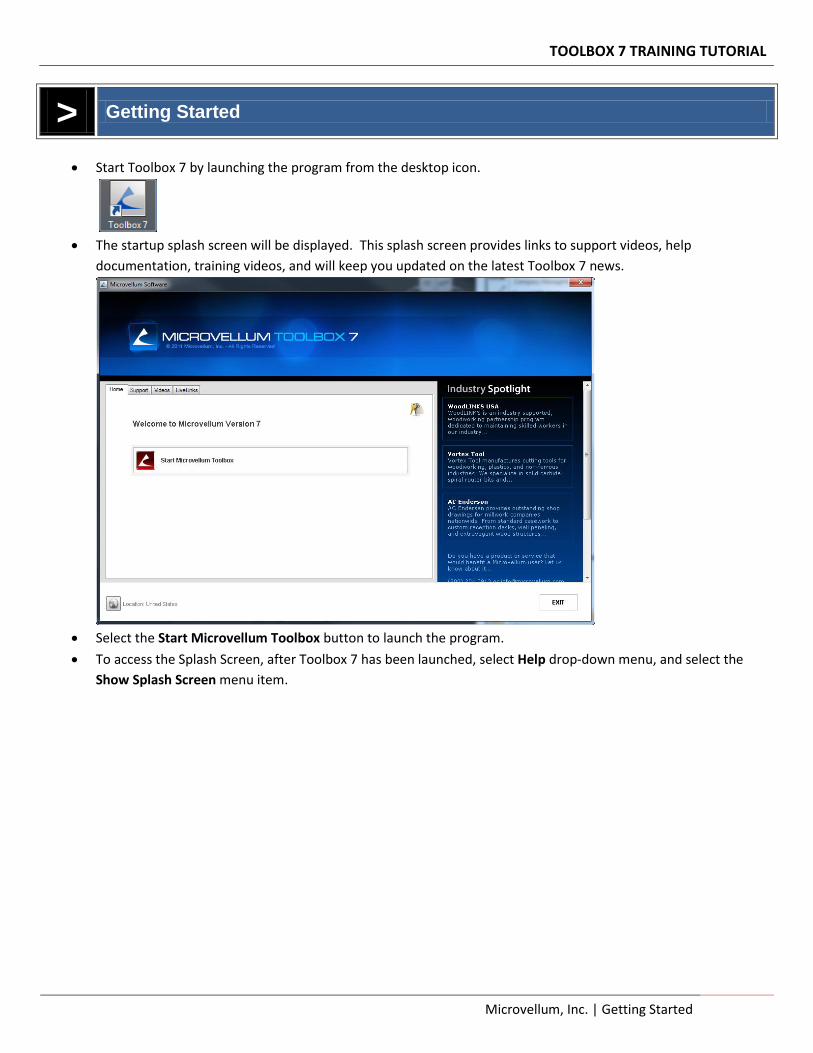
Start Toolbox 7 by launching the program from the desktop icon.
The startup splash screen will be displayed. This splash screen provides links to support videos, help
documentation, training videos, and will keep you updated on the latest Toolbox 7 news.
Select the Start Microvellum Toolbox button to launch the program.
To access the Splash Screen, after Toolbox 7 has been launched, select Help drop-down menu, and select the
Show Splash Screen menu item.
TOOLBOX 7 TRAINING TUTORIAL
2 Getting Started | Microvellum, Inc.
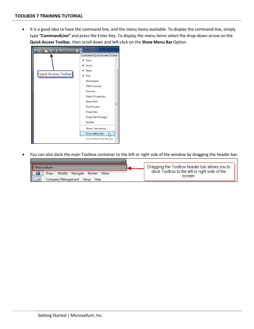
It is a good idea to have the command line, and the menu items available. To display the command line, simply
type “CommandLine” and press the Enter Key. To display the menu items select the drop-down arrow on the
Quick Access Toolbar, then scroll down and left-click on the Show Menu Bar Option.
You can also dock the main Toolbox container to the left or right side of the window by dragging the header bar.
TOOLBOX 7 TRAINING TUTORIAL
Microvellum, Inc. | Getting Started 3
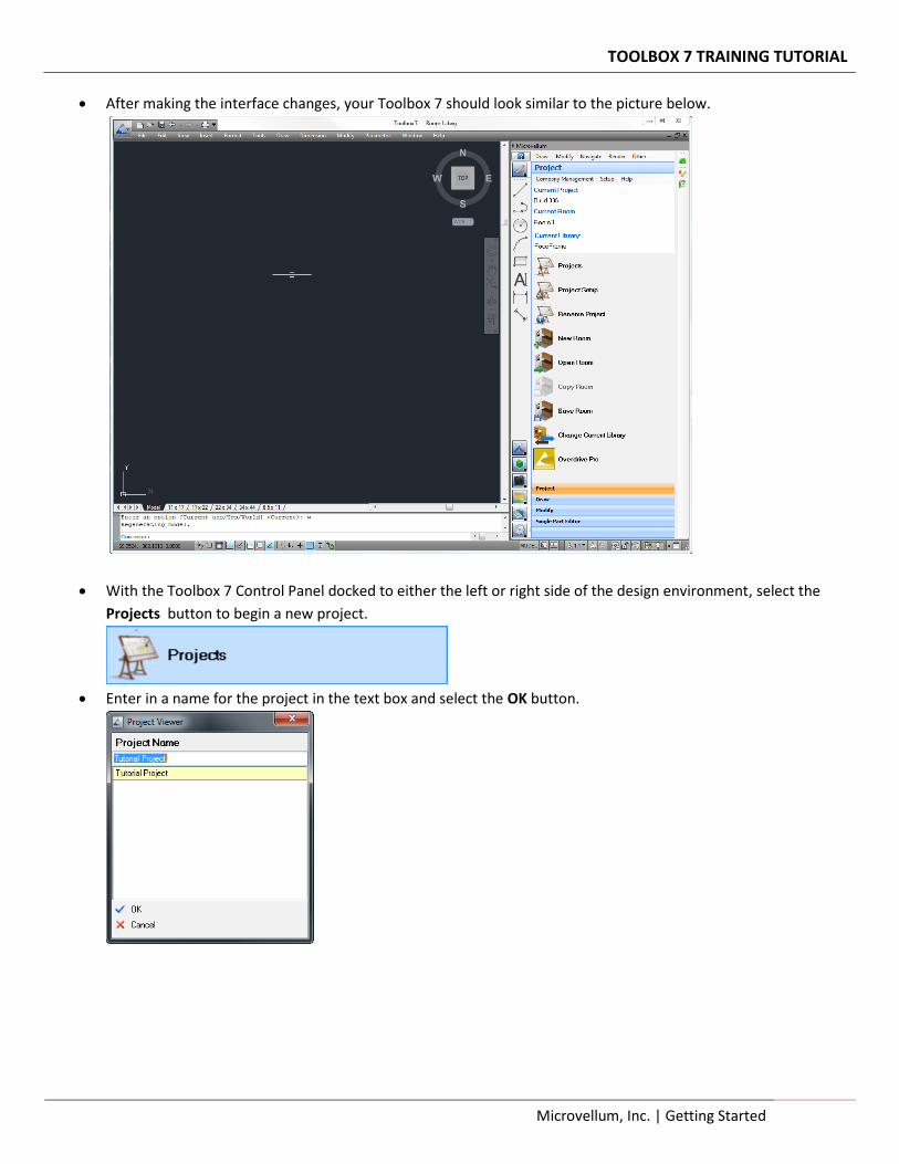
After making the interface changes, your Toolbox 7 should look similar to the picture below.
With the Toolbox 7 Control Panel docked to either the left or right side of the design environment, select the
Projects button to begin a new project.
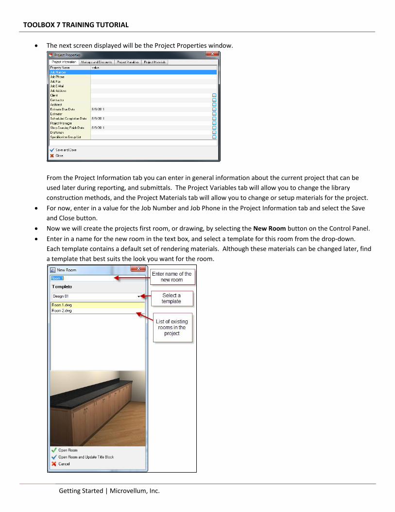
Enter in a name for the project in the text box and select the OK button.
TOOLBOX 7 TRAINING TUTORIAL
4 Getting Started | Microvellum, Inc.
The next screen displayed will be the Project Properties window.
From the Project Information tab you can enter in general information about the current project that can be
used later during reporting, and submittals. The Project Variables tab will allow you to change the library
construction methods, and the Project Materials tab will allow you to change or setup materials for the project.
For now, enter in a value for the Job Number and Job Phone in the Project Information tab and select the Save
and Close button.
Now we will create the projects first room, or drawing, by selecting the New Room button on the Control Panel.
Enter in a name for the new room in the text box, and select a template for this room from the drop-down.
Each template contains a default set of rendering materials. Although these materials can be changed later, find
a template that best suits the look you want for the room.
TOOLBOX 7 TRAINING TUTORIAL
Microvellum, Inc. | Getting Started 5
At the bottom of this window are two options, Open Room and Open Room and Update Title Block. Select the
Open Room and Update Title Block button to create the new room and update the values we assigned in the
Project Properties screen to this drawing.
Because we selected this option when creating the new room, the information we entered in the Project
Properties tab will be added to the title block in the drawing. In later chapters we will discuss in further detail
how the title block works when creating submittals.
Review
In this chapter we started the Toolbox 7 program and learned how we can customize the interface to include the
command line and additional drop-down menu items. We also saw how to use the Toolbox header to dock the Toolbox
to the left or right portion of the screen. We also took the first steps in the design process by creating a project, using
the project properties screen and creating a room for the project.
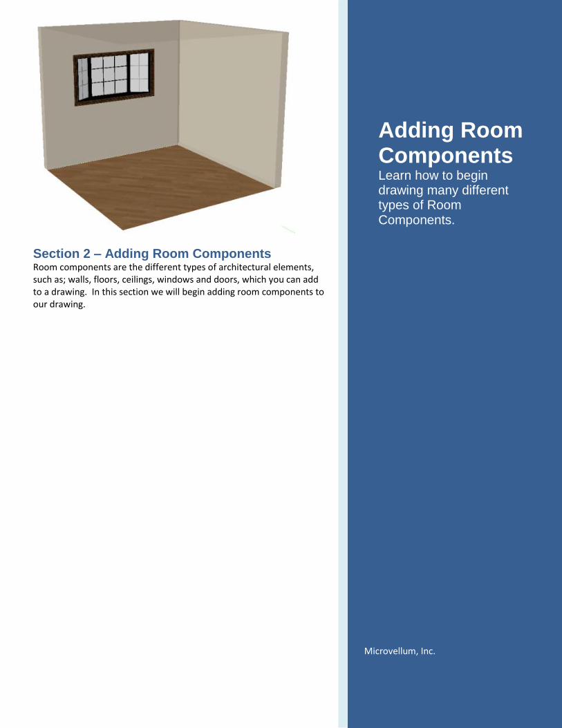
Section 2 – Adding Room Components Room components are the different types of architectural elements, such as; walls, floors, ceilings, windows and doors, which you can add to a drawing. In this section we will begin adding room components to our drawing.
Adding Room Components Learn how to begin drawing many different types of Room Components.
Microvellum, Inc.
TOOLBOX 7 TRAINING TUTORIAL
Microvellum, Inc. | Adding Room Components 7
> Adding Room Components
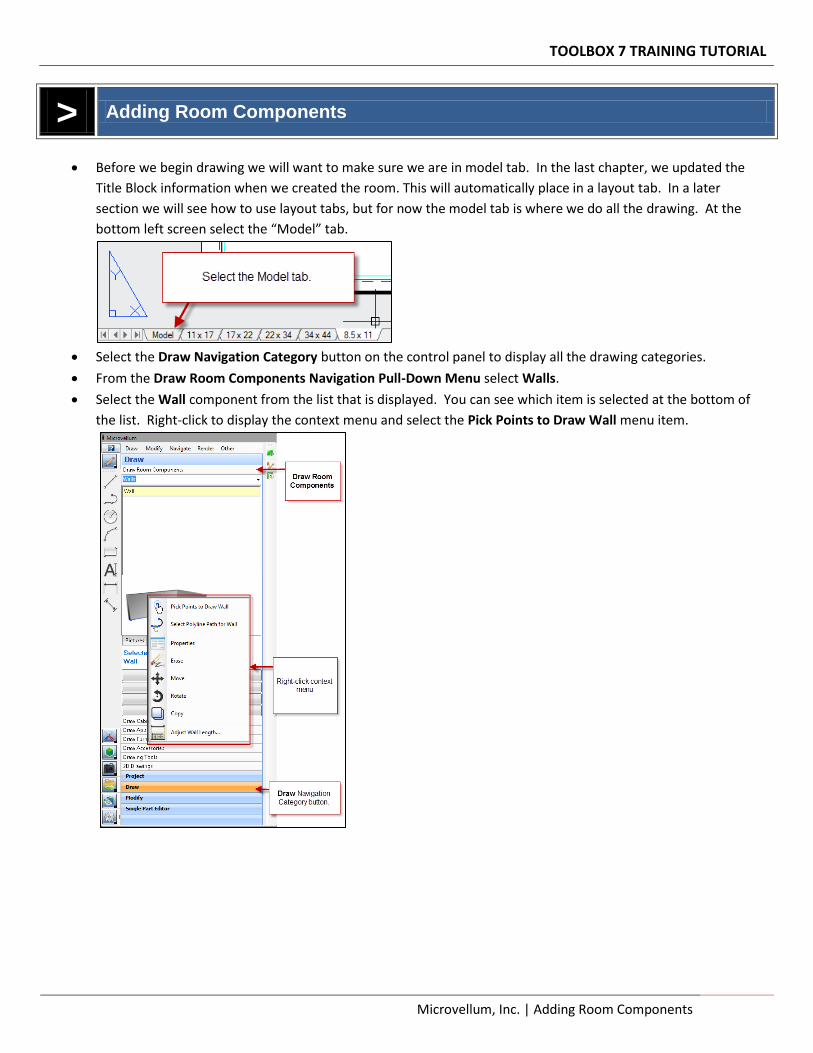
Before we begin drawing we will want to make sure we are in model tab. In the last chapter, we updated the
Title Block information when we created the room. This will automatically place in a layout tab. In a later
section we will see how to use layout tabs, but for now the model tab is where we do all the drawing. At the
bottom left screen select the “Model” tab.
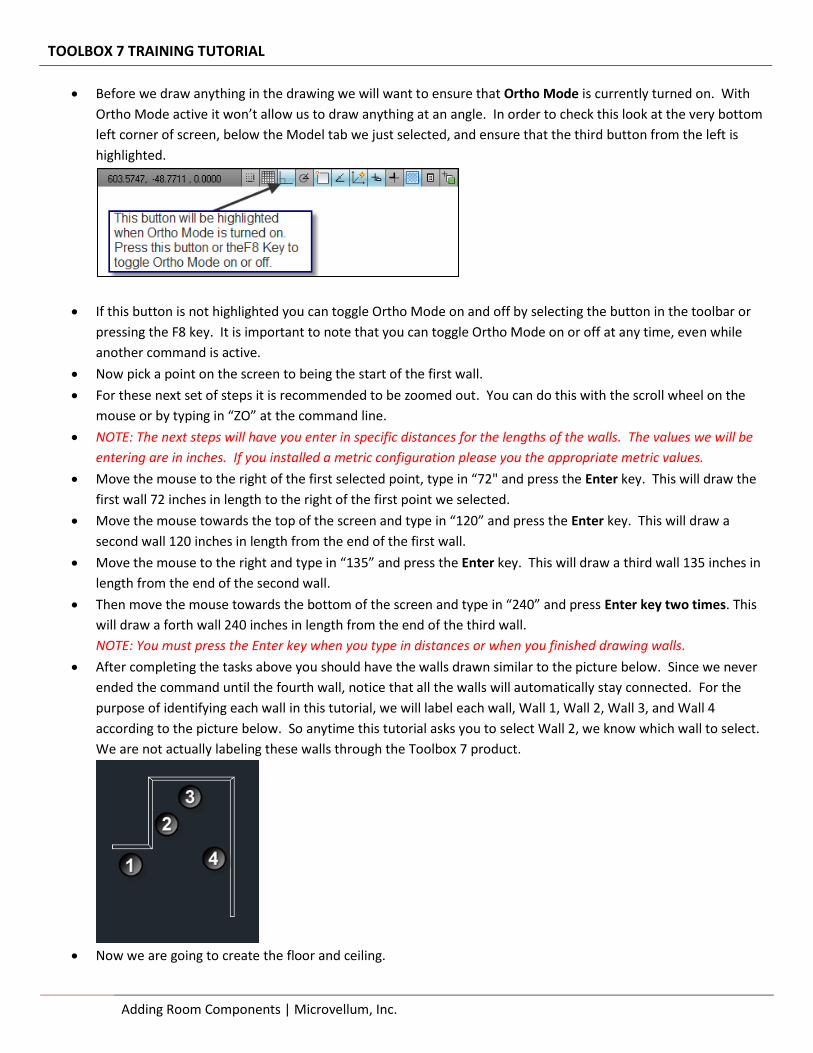
Select the Draw Navigation Category button on the control panel to display all the drawing categories.
From the Draw Room Components Navigation Pull-Down Menu select Walls.
Select the Wall component from the list that is displayed. You can see which item is selected at the bottom of
the list. Right-click to display the context menu and select the Pick Points to Draw Wall menu item.
TOOLBOX 7 TRAINING TUTORIAL
8 Adding Room Components | Microvellum, Inc.
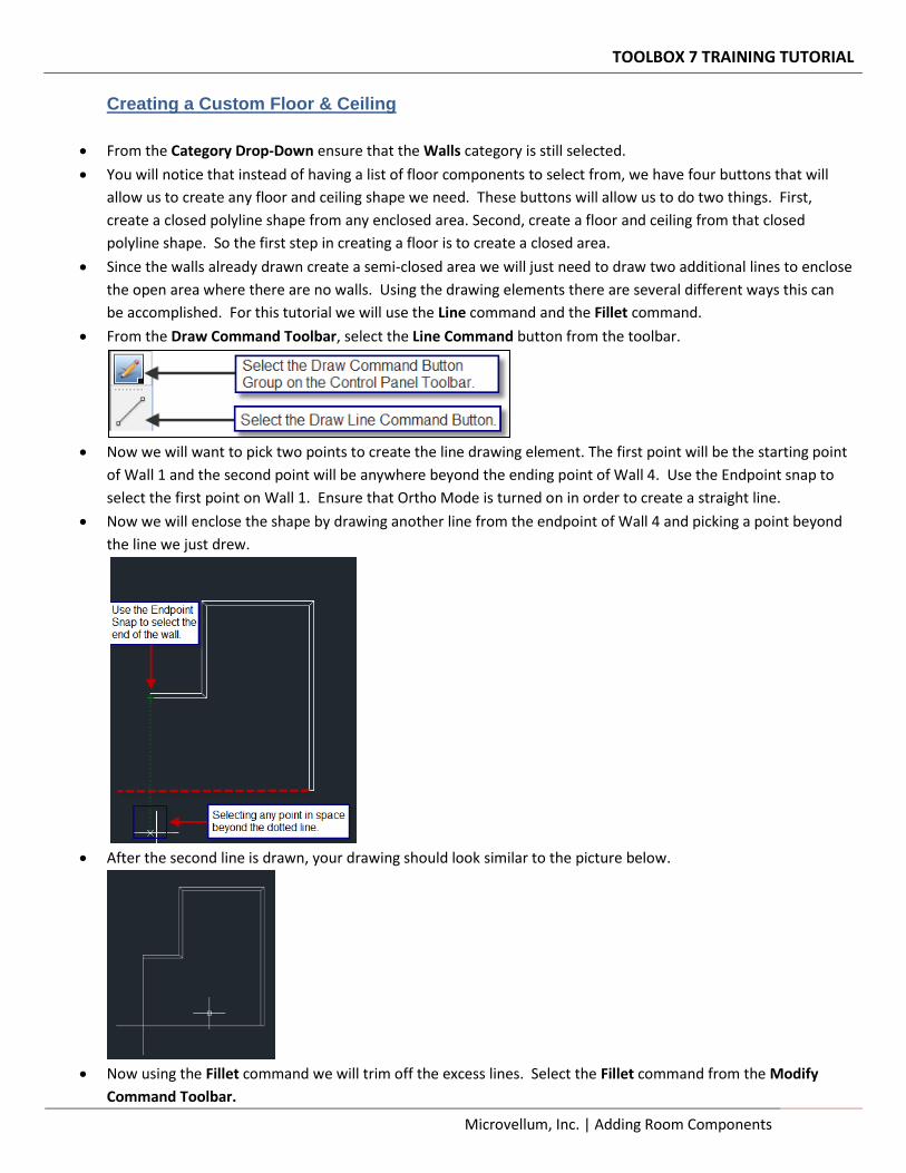
Before we draw anything in the drawing we will want to ensure that Ortho Mode is currently turned on. With
Ortho Mode active it won’t allow us to draw anything at an angle. In order to check this look at the very bottom
left corner of screen, below the Model tab we just selected, and ensure that the third button from the left is
highlighted.
If this button is not highlighted you can toggle Ortho Mode on and off by selecting the button in the toolbar or
pressing the F8 key. It is important to note that you can toggle Ortho Mode on or off at any time, even while
another command is active.
Now pick a point on the screen to being the start of the first wall.
For these next set of steps it is recommended to be zoomed out. You can do this with the scroll wheel on the
mouse or by typing in “ZO” at the command line.
NOTE: The next steps will have you enter in specific distances for the lengths of the walls. The values we will be
entering are in inches. If you installed a metric configuration please you the appropriate metric values.
Move the mouse to the right of the first selected point, type in “72" and press the Enter key. This will draw the
first wall 72 inches in length to the right of the first point we selected.
Move the mouse towards the top of the screen and type in “120” and press the Enter key. This will draw a
second wall 120 inches in length from the end of the first wall.
Move the mouse to the right and type in “135” and press the Enter key. This will draw a third wall 135 inches in
length from the end of the second wall.
Then move the mouse towards the bottom of the screen and type in “240” and press Enter key two times. This
will draw a forth wall 240 inches in length from the end of the third wall.
NOTE: You must press the Enter key when you type in distances or when you finished drawing walls.
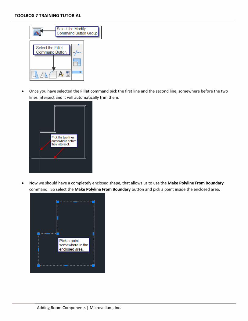
After completing the tasks above you should have the walls drawn similar to the picture below. Since we never
ended the command until the fourth wall, notice that all the walls will automatically stay connected. For the
purpose of identifying each wall in this tutorial, we will label each wall, Wall 1, Wall 2, Wall 3, and Wall 4
according to the picture below. So anytime this tutorial asks you to select Wall 2, we know which wall to select.
We are not actually labeling these walls through the Toolbox 7 product.
Now we are going to create the floor and ceiling.
TOOLBOX 7 TRAINING TUTORIAL
Microvellum, Inc. | Adding Room Components 9
Creating a Custom Floor & Ceiling
From the Category Drop-Down ensure that the Walls category is still selected.
You will notice that instead of having a list of floor components to select from, we have four buttons that will
allow us to create any floor and ceiling shape we need. These buttons will allow us to do two things. First,
create a closed polyline shape from any enclosed area. Second, create a floor and ceiling from that closed
polyline shape. So the first step in creating a floor is to create a closed area.
Since the walls already drawn create a semi-closed area we will just need to draw two additional lines to enclose
the open area where there are no walls. Using the drawing elements there are several different ways this can
be accomplished. For this tutorial we will use the Line command and the Fillet command.
From the Draw Command Toolbar, select the Line Command button from the toolbar.
Now we will want to pick two points to create the line drawing element. The first point will be the starting point
of Wall 1 and the second point will be anywhere beyond the ending point of Wall 4. Use the Endpoint snap to
select the first point on Wall 1. Ensure that Ortho Mode is turned on in order to create a straight line.
Now we will enclose the shape by drawing another line from the endpoint of Wall 4 and picking a point beyond
the line we just drew.
After the second line is drawn, your drawing should look similar to the picture below.
Now using the Fillet command we will trim off the excess lines. Select the Fillet command from the Modify
Command Toolbar.
TOOLBOX 7 TRAINING TUTORIAL
10 Adding Room Components | Microvellum, Inc.
Once you have selected the Fillet command pick the first line and the second line, somewhere before the two
lines intersect and it will automatically trim them.
Now we should have a completely enclosed shape, that allows us to use the Make Polyline From Boundary
command. So select the Make Polyline From Boundary button and pick a point inside the enclosed area.
TOOLBOX 7 TRAINING TUTORIAL
Microvellum, Inc. | Adding Room Components 11
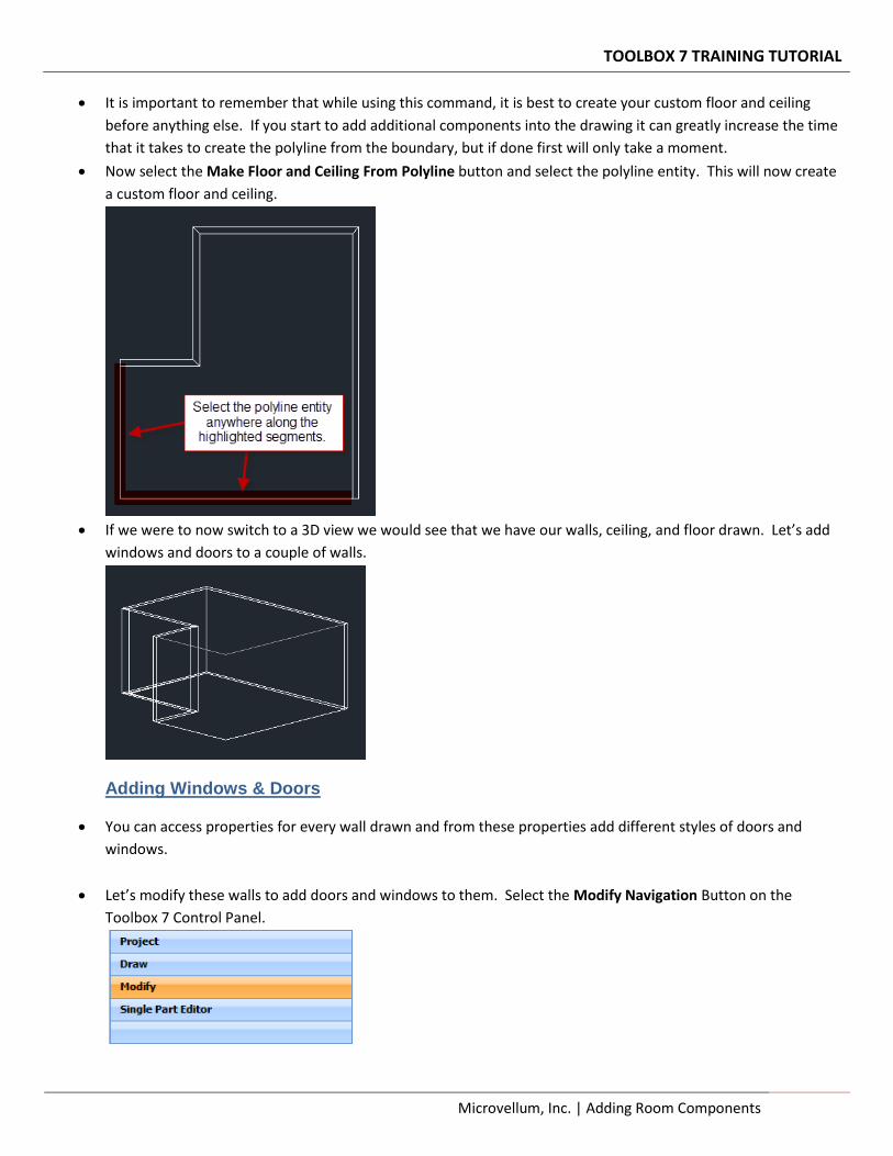
It is important to remember that while using this command, it is best to create your custom floor and ceiling
before anything else. If you start to add additional components into the drawing it can greatly increase the time
that it takes to create the polyline from the boundary, but if done first will only take a moment.
Now select the Make Floor and Ceiling From Polyline button and select the polyline entity. This will now create
a custom floor and ceiling.
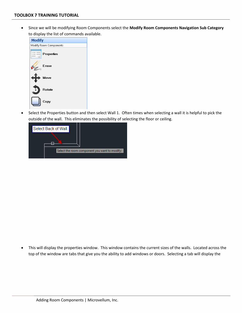
If we were to now switch to a 3D view we would see that we have our walls, ceiling, and floor drawn. Let’s add
windows and doors to a couple of walls.
Adding Windows & Doors
You can access properties for every wall drawn and from these properties add different styles of doors and
windows.
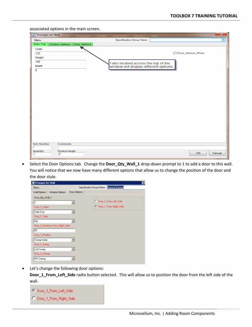
Let’s modify these walls to add doors and windows to them. Select the Modify Navigation Button on the
Toolbox 7 Control Panel.
TOOLBOX 7 TRAINING TUTORIAL
12 Adding Room Components | Microvellum, Inc.
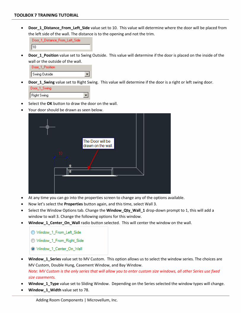
Since we will be modifying Room Components select the Modify Room Components Navigation Sub Category
to display the list of commands available.
Select the Properties button and then select Wall 1. Often times when selecting a wall it is helpful to pick the
outside of the wall. This eliminates the possibility of selecting the floor or ceiling.
This will display the properties window. This window contains the current sizes of the walls. Located across the
top of the window are tabs that give you the ability to add windows or doors. Selecting a tab will display the
TOOLBOX 7 TRAINING TUTORIAL
Microvellum, Inc. | Adding Room Components 13
associated options in the main screen.
Select the Door Options tab. Change the Door_Qty_Wall_1 drop-down prompt to 1 to add a door to this wall.
You will notice that we now have many different options that allow us to change the position of the door and
the door style.
Let’s change the following door options:
Door_1_From_Left_Side radio button selected. This will allow us to position the door from the left side of the
wall.
TOOLBOX 7 TRAINING TUTORIAL
14 Adding Room Components | Microvellum, Inc.
Door_1_Distance_From_Left_Side value set to 10. This value will determine where the door will be placed from
the left side of the wall. The distance is to the opening and not the trim.
Door_1_Position value set to Swing Outside. This value will determine if the door is placed on the inside of the
wall or the outside of the wall.
Door_1_Swing value set to Right Swing. This value will determine if the door is a right or left swing door.
Select the OK button to draw the door on the wall.
Your door should be drawn as seen below.
At any time you can go into the properties screen to change any of the options available.
Now let’s select the Properties button again, and this time, select Wall 3.
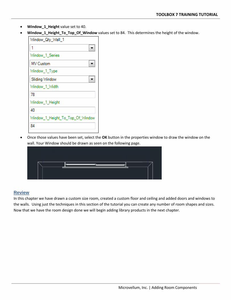
Select the Window Options tab. Change the Window_Qty_Wall_1 drop-down prompt to 1, this will add a
window to wall 3. Change the following options for this window.
Window_1_Center_On_Wall radio button selected. This will center the window on the wall.
Window_1_Series value set to MV Custom. This option allows us to select the window series. The choices are
MV Custom, Double Hung, Casement Window, and Bay Window.
Note: MV Custom is the only series that will allow you to enter custom size windows, all other Series use fixed
size casements.
Window_1_Type value set to Sliding Window. Depending on the Series selected the window types will change.
Window_1_Width value set to 78.
TOOLBOX 7 TRAINING TUTORIAL
Microvellum, Inc. | Adding Room Components 15
Window_1_Height value set to 40.
Window_1_Height_To_Top_Of_Window values set to 84. This determines the height of the window.
Once those values have been set, select the OK button in the properties window to draw the window on the
wall. Your Window should be drawn as seen on the following page.
Review
In this chapter we have drawn a custom size room, created a custom floor and ceiling and added doors and windows to
the walls. Using just the techniques in this section of the tutorial you can create any number of room shapes and sizes.
Now that we have the room design done we will begin adding library products in the next chapter.

TOOLBOX 7 TRAINING TUTORIAL
16 Adding Room Components | Microvellum, Inc.
Section 3 – Adding Products & Appliances Now that the room design is completed we will begin adding cabinets to the drawing. This chapter is going to focus on using different placement methods.
Adding Products & Appliances Begin adding different types of cabinets and appliances to your drawing.
Microvellum, Inc.
TOOLBOX 7 TRAINING TUTORIAL
18 Adding Products & Appliances | Microvellum, Inc.
> Adding Products & Appliances
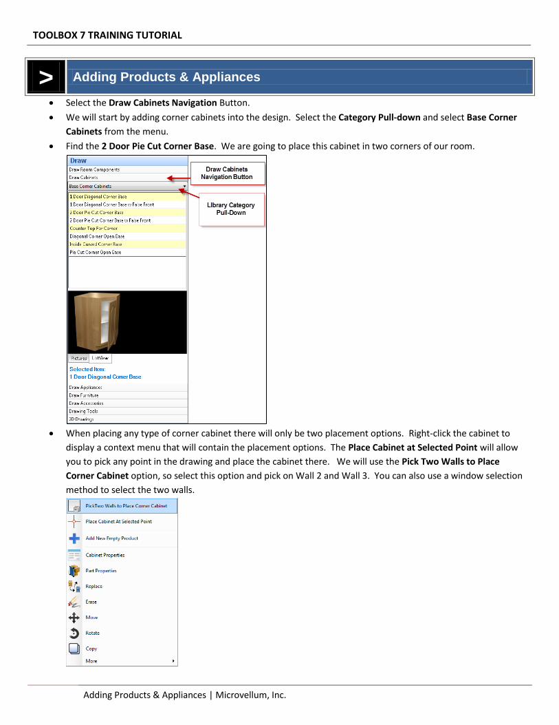
Select the Draw Cabinets Navigation Button.
We will start by adding corner cabinets into the design. Select the Category Pull-down and select Base Corner
Cabinets from the menu.
Find the 2 Door Pie Cut Corner Base. We are going to place this cabinet in two corners of our room.
When placing any type of corner cabinet there will only be two placement options. Right-click the cabinet to
display a context menu that will contain the placement options. The Place Cabinet at Selected Point will allow
you to pick any point in the drawing and place the cabinet there. We will use the Pick Two Walls to Place
Corner Cabinet option, so select this option and pick on Wall 2 and Wall 3. You can also use a window selection
method to select the two walls.
TOOLBOX 7 TRAINING TUTORIAL
Microvellum, Inc. | Adding Products & Appliances 19
The properties window will be displayed that would allow us to modify a number of options for this cabinet. For
now let’s leave everything the same and select the OK button. The cabinet will be drawn into the room where
we specified.
Repeat this process and place a 2 Door Pie Cut Corner Base product in the opposite corner of the room.
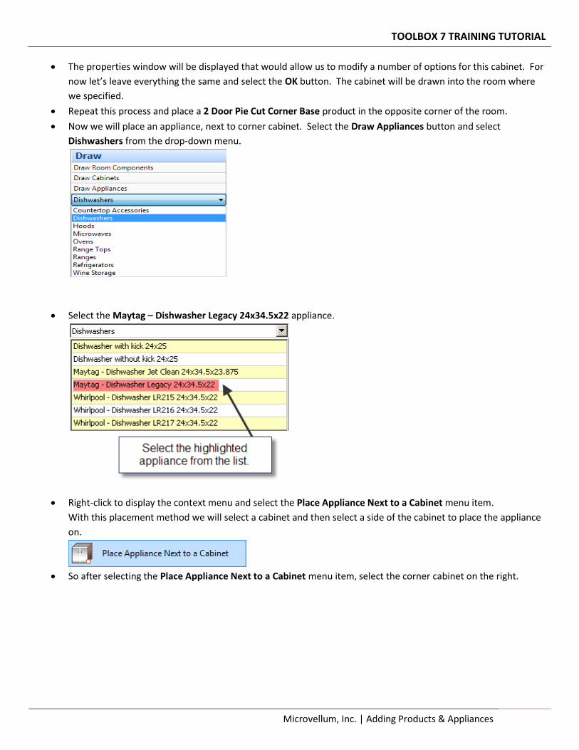
Now we will place an appliance, next to corner cabinet. Select the Draw Appliances button and select
Dishwashers from the drop-down menu.
Select the Maytag – Dishwasher Legacy 24x34.5x22 appliance.
Right-click to display the context menu and select the Place Appliance Next to a Cabinet menu item.
With this placement method we will select a cabinet and then select a side of the cabinet to place the appliance
on.
So after selecting the Place Appliance Next to a Cabinet menu item, select the corner cabinet on the right.
TOOLBOX 7 TRAINING TUTORIAL
20 Adding Products & Appliances | Microvellum, Inc.
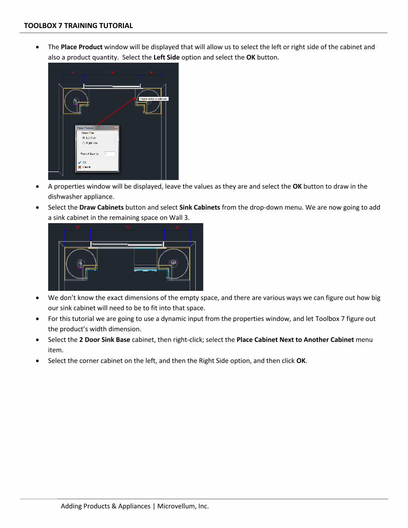
The Place Product window will be displayed that will allow us to select the left or right side of the cabinet and
also a product quantity. Select the Left Side option and select the OK button.
A properties window will be displayed, leave the values as they are and select the OK button to draw in the
dishwasher appliance.
Select the Draw Cabinets button and select Sink Cabinets from the drop-down menu. We are now going to add
a sink cabinet in the remaining space on Wall 3.
We don’t know the exact dimensions of the empty space, and there are various ways we can figure out how big
our sink cabinet will need to be to fit into that space.
For this tutorial we are going to use a dynamic input from the properties window, and let Toolbox 7 figure out
the product’s width dimension.
Select the 2 Door Sink Base cabinet, then right-click; select the Place Cabinet Next to Another Cabinet menu
item.
Select the corner cabinet on the left, and then the Right Side option, and then click OK.
TOOLBOX 7 TRAINING TUTORIAL
Microvellum, Inc. | Adding Products & Appliances 21
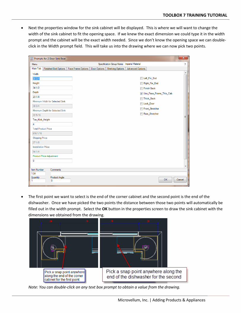
Next the properties window for the sink cabinet will be displayed. This is where we will want to change the
width of the sink cabinet to fit the opening space. If we knew the exact dimension we could type it in the width
prompt and the cabinet will be the exact width needed. Since we don’t know the opening space we can double-
click in the Width prompt field. This will take us into the drawing where we can now pick two points.
The first point we want to select is the end of the corner cabinet and the second point is the end of the
dishwasher. Once we have picked the two points the distance between those two points will automatically be
filled out in the width prompt. Select the OK button in the properties screen to draw the sink cabinet with the
dimensions we obtained from the drawing.
Note: You can double-click on any text box prompt to obtain a value from the drawing.
TOOLBOX 7 TRAINING TUTORIAL
22 Adding Products & Appliances | Microvellum, Inc.
After adding the sink cabinet your room should look like this:
We will now use a few more placement methods to place cabinets in a room. This time placing a non-corner
cabinet on a wall.
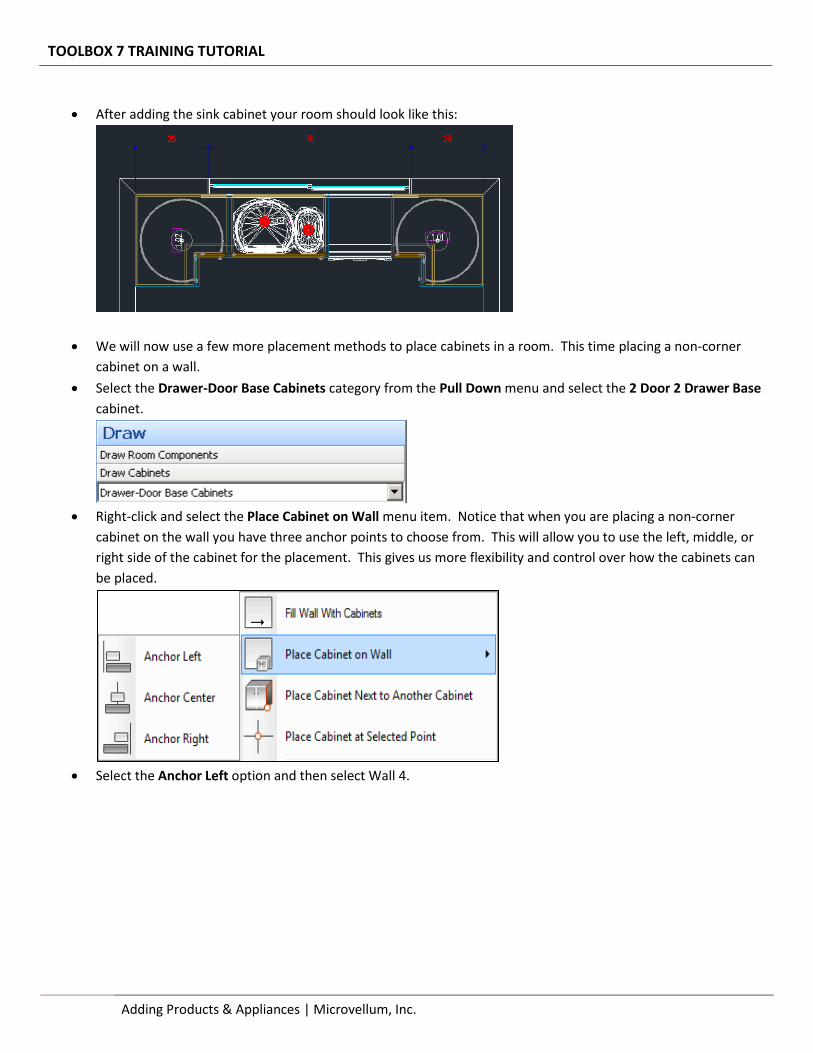
Select the Drawer-Door Base Cabinets category from the Pull Down menu and select the 2 Door 2 Drawer Base
cabinet.
Right-click and select the Place Cabinet on Wall menu item. Notice that when you are placing a non-corner
cabinet on the wall you have three anchor points to choose from. This will allow you to use the left, middle, or
right side of the cabinet for the placement. This gives us more flexibility and control over how the cabinets can
be placed.
Select the Anchor Left option and then select Wall 4.
TOOLBOX 7 TRAINING TUTORIAL
Microvellum, Inc. | Adding Products & Appliances 23
We are going to use the snaps to pick the end of the corner cabinet on the right and place the cabinet next to it
on the wall. When the Product Prompts dialog appears accept the defaults and press the OK button.
We will now place a Range next to the 2 Door 2 Drawer cabinet, we will use a similar placement method as
before, but this time we will use a distance from the corner.
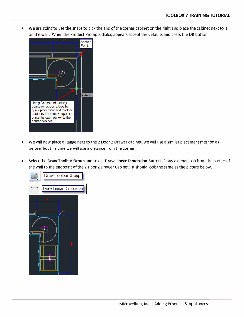
Select the Draw Toolbar Group and select Draw Linear Dimension Button. Draw a dimension from the corner of
the wall to the endpoint of the 2 Door 2 Drawer Cabinet. It should look the same as the picture below.
TOOLBOX 7 TRAINING TUTORIAL
24 Adding Products & Appliances | Microvellum, Inc.
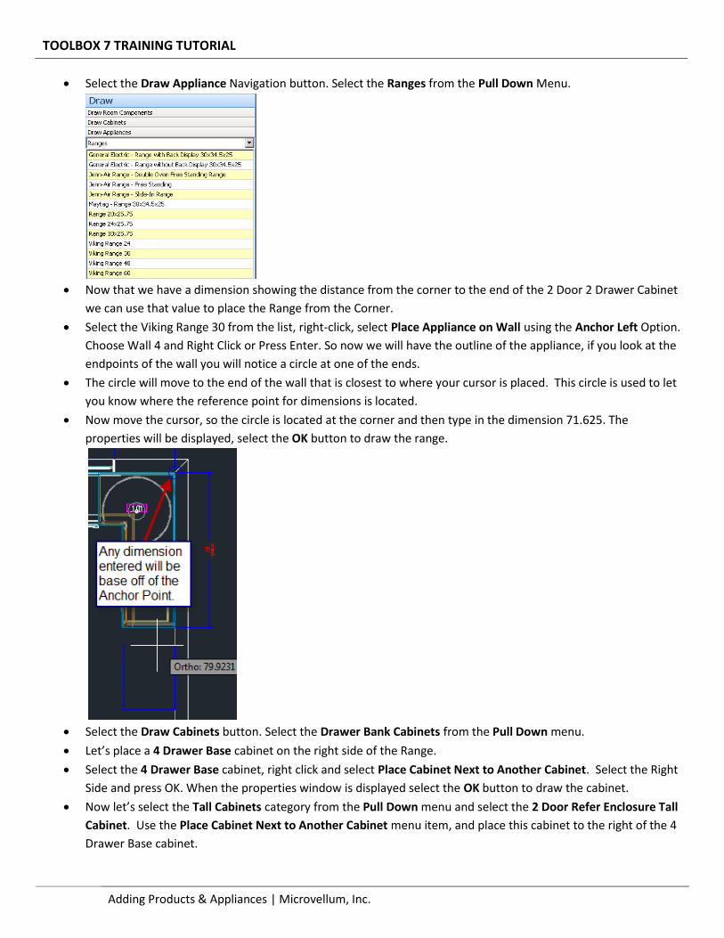
Select the Draw Appliance Navigation button. Select the Ranges from the Pull Down Menu.
Now that we have a dimension showing the distance from the corner to the end of the 2 Door 2 Drawer Cabinet
we can use that value to place the Range from the Corner.
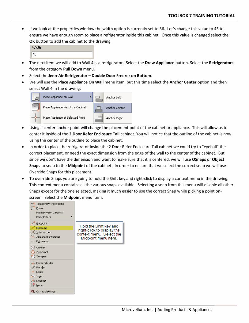
Select the Viking Range 30 from the list, right-click, select Place Appliance on Wall using the Anchor Left Option.
Choose Wall 4 and Right Click or Press Enter. So now we will have the outline of the appliance, if you look at the
endpoints of the wall you will notice a circle at one of the ends.
The circle will move to the end of the wall that is closest to where your cursor is placed. This circle is used to let
you know where the reference point for dimensions is located.
Now move the cursor, so the circle is located at the corner and then type in the dimension 71.625. The
properties will be displayed, select the OK button to draw the range.
Select the Draw Cabinets button. Select the Drawer Bank Cabinets from the Pull Down menu.
Let’s place a 4 Drawer Base cabinet on the right side of the Range.
Select the 4 Drawer Base cabinet, right click and select Place Cabinet Next to Another Cabinet. Select the Right
Side and press OK. When the properties window is displayed select the OK button to draw the cabinet.
Now let’s select the Tall Cabinets category from the Pull Down menu and select the 2 Door Refer Enclosure Tall
Cabinet. Use the Place Cabinet Next to Another Cabinet menu item, and place this cabinet to the right of the 4
Drawer Base cabinet.
TOOLBOX 7 TRAINING TUTORIAL
Microvellum, Inc. | Adding Products & Appliances 25
If we look at the properties window the width option is currently set to 36. Let’s change this value to 45 to
ensure we have enough room to place a refrigerator inside this cabinet. Once this value is changed select the
OK button to add the cabinet to the drawing.
The next item we will add to Wall 4 is a refrigerator. Select the Draw Appliance button. Select the Refrigerators
from the category Pull Down menu.
Select the Jenn-Air Refrigerator – Double Door Freezer on Bottom.
We will use the Place Appliance On Wall menu item, but this time select the Anchor Center option and then
select Wall 4 in the drawing.
Using a center anchor point will change the placement point of the cabinet or appliance. This will allow us to
center it inside of the 2 Door Refer Enclosure Tall cabinet. You will notice that the outline of the cabinet is now
using the center of the outline to place the cabinet.
In order to place the refrigerator inside the 2 Door Refer Enclosure Tall cabinet we could try to “eyeball” the
correct placement, or need the exact dimension from the edge of the wall to the center of the cabinet. But
since we don’t have the dimension and want to make sure that it is centered, we will use OSnaps or Object
Snaps to snap to the Midpoint of the cabinet. In order to ensure that we select the correct snap we will use
Override Snaps for this placement.
To override Snaps you are going to hold the Shift key and right-click to display a context menu in the drawing.
This context menu contains all the various snaps available. Selecting a snap from this menu will disable all other
Snaps except for the one selected, making it much easier to use the correct Snap while picking a point on-
screen. Select the Midpoint menu item.
TOOLBOX 7 TRAINING TUTORIAL
26 Adding Products & Appliances | Microvellum, Inc.
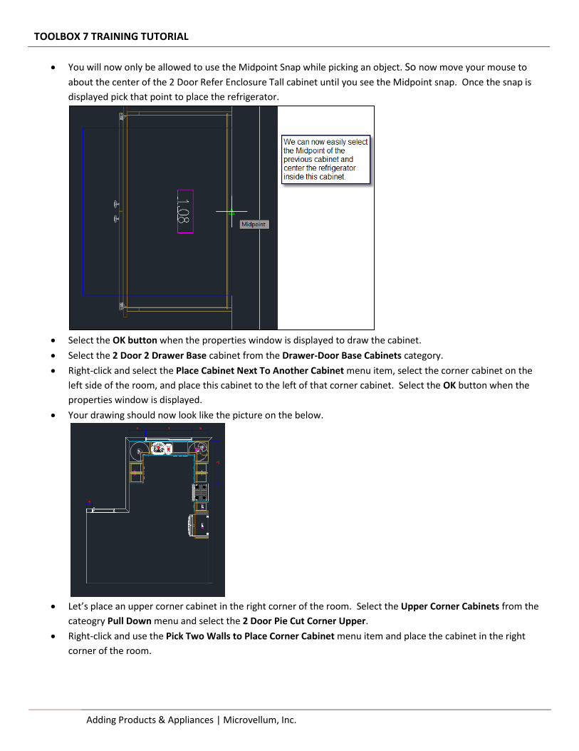
You will now only be allowed to use the Midpoint Snap while picking an object. So now move your mouse to
about the center of the 2 Door Refer Enclosure Tall cabinet until you see the Midpoint snap. Once the snap is
displayed pick that point to place the refrigerator.
Select the OK button when the properties window is displayed to draw the cabinet.
Select the 2 Door 2 Drawer Base cabinet from the Drawer-Door Base Cabinets category.
Right-click and select the Place Cabinet Next To Another Cabinet menu item, select the corner cabinet on the
left side of the room, and place this cabinet to the left of that corner cabinet. Select the OK button when the
properties window is displayed.
Your drawing should now look like the picture on the below.
Let’s place an upper corner cabinet in the right corner of the room. Select the Upper Corner Cabinets from the
cateogry Pull Down menu and select the 2 Door Pie Cut Corner Upper.
Right-click and use the Pick Two Walls to Place Corner Cabinet menu item and place the cabinet in the right
corner of the room.
TOOLBOX 7 TRAINING TUTORIAL
Microvellum, Inc. | Adding Products & Appliances 27
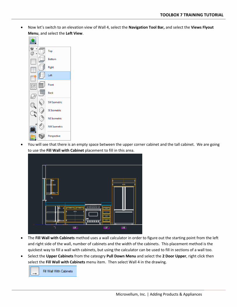
Now let’s switch to an elevation view of Wall 4, select the Navigation Tool Bar, and select the Views Flyout
Menu, and select the Left View.
You will see that there is an empty space between the upper corner cabinet and the tall cabinet. We are going
to use the Fill Wall with Cabinet placement to fill in this area.
The Fill Wall with Cabinets method uses a wall calculator in order to figure out the starting point from the left
and right side of the wall, number of cabinets and the width of the cabinets. This placement method is the
quickest way to fill a wall with cabinets, but using the calculator can be used to fill in sections of a wall too.
Select the Upper Cabinets from the cateogry Pull Down Menu and select the 2 Door Upper, right click then
select the Fill Wall with Cabinets menu item. Then select Wall 4 in the drawing.
TOOLBOX 7 TRAINING TUTORIAL
28 Adding Products & Appliances | Microvellum, Inc.
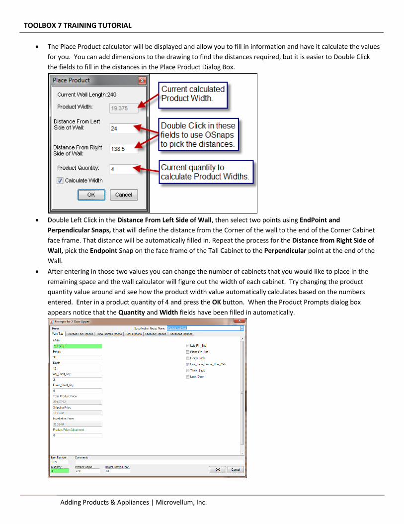
The Place Product calculator will be displayed and allow you to fill in information and have it calculate the values
for you. You can add dimensions to the drawing to find the distances required, but it is easier to Double Click
the fields to fill in the distances in the Place Product Dialog Box.
Double Left Click in the Distance From Left Side of Wall, then select two points using EndPoint and
Perpendicular Snaps, that will define the distance from the Corner of the wall to the end of the Corner Cabinet
face frame. That distance will be automatically filled in. Repeat the process for the Distance from Right Side of
Wall, pick the Endpoint Snap on the face frame of the Tall Cabinet to the Perpendicular point at the end of the
Wall.
After entering in those two values you can change the number of cabinets that you would like to place in the
remaining space and the wall calculator will figure out the width of each cabinet. Try changing the product
quantity value around and see how the product width value automatically calculates based on the numbers
entered. Enter in a product quantity of 4 and press the OK button. When the Product Prompts dialog box
appears notice that the Quantity and Width fields have been filled in automatically.
TOOLBOX 7 TRAINING TUTORIAL
Microvellum, Inc. | Adding Products & Appliances 29
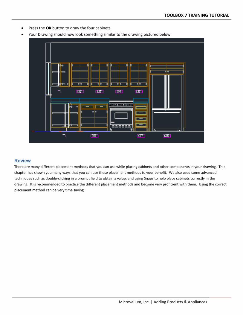
Press the OK button to draw the four cabinets.
Your Drawing should now look something similar to the drawing pictured below.
Review
There are many different placement methods that you can use while placing cabinets and other components in your drawing. This
chapter has shown you many ways that you can use these placement methods to your benefit. We also used some advanced
techniques such as double-clicking in a prompt field to obtain a value, and using Snaps to help place cabinets correctly in the
drawing. It is recommended to practice the different placement methods and become very proficient with them. Using the correct
placement method can be very time saving.

Section 4 – Navigating the Drawing Learning how to navigate a drawing properly is critical when designing a room. Using the correct navigation tools, and views will not only speed up your drawing time, but ensure you get the results you are looking for. In this chapter we won’t be making any changes to the drawing, but instead focus on the commands available from the navigation menu.
Navigating the Drawing Learn how to display different views in the drawing to get a better look at the design.
Microvellum, Inc.
TOOLBOX 7 TRAINING TUTORIAL
Microvellum, Inc. | Navigating the Drawing 31
> Navigating the Drawing
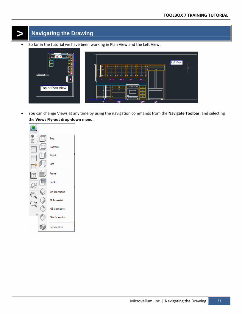
So far in the tutorial we have been working in Plan View and the Left View.
You can change Views at any time by using the navigation commands from the Navigate Toolbar, and selecting
the Views Fly-out drop-down menu.
TOOLBOX 7 TRAINING TUTORIAL
32 Navigating the Drawing | Microvellum, Inc.
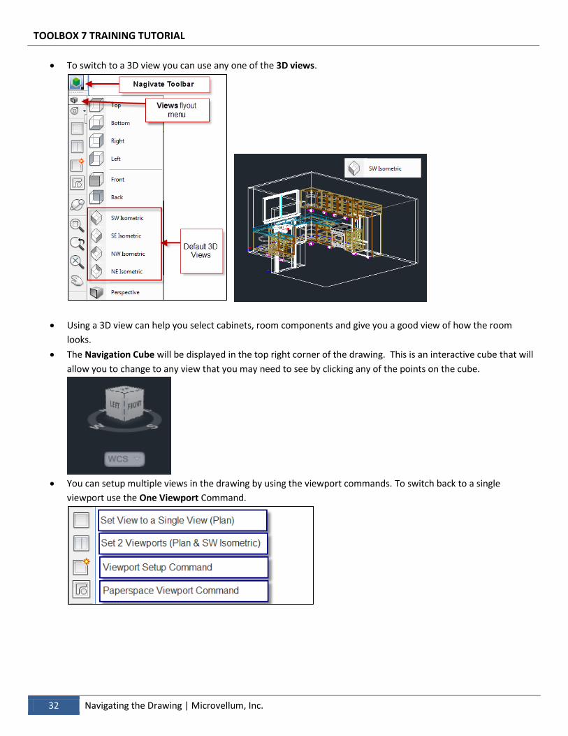
To switch to a 3D view you can use any one of the 3D views.
Using a 3D view can help you select cabinets, room components and give you a good view of how the room
looks.
The Navigation Cube will be displayed in the top right corner of the drawing. This is an interactive cube that will
allow you to change to any view that you may need to see by clicking any of the points on the cube.
You can setup multiple views in the drawing by using the viewport commands. To switch back to a single
viewport use the One Viewport Command.
TOOLBOX 7 TRAINING TUTORIAL
Microvellum, Inc. | Navigating the Drawing 33
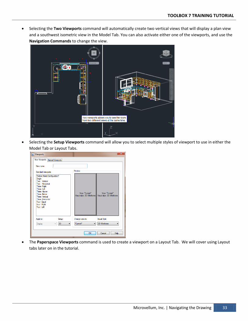
Selecting the Two Viewports command will automatically create two vertical views that will display a plan view
and a southwest isometric view in the Model Tab. You can also activate either one of the viewports, and use the
Navigation Commands to change the view.
Selecting the Setup Viewports command will allow you to select multiple styles of viewport to use in either the
Model Tab or Layout Tabs.
The Paperspace Viewports command is used to create a viewport on a Layout Tab. We will cover using Layout
tabs later on in the tutorial.
TOOLBOX 7 TRAINING TUTORIAL
34 Navigating the Drawing | Microvellum, Inc.
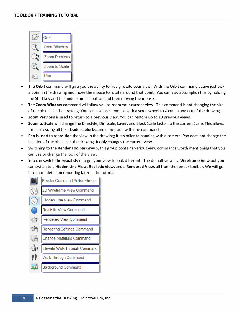
The Orbit command will give you the ability to freely rotate your view. With the Orbit command active just pick
a point in the drawing and move the mouse to rotate around that point. You can also accomplish this by holding
the Shift key and the middle mouse button and then moving the mouse.
The Zoom Window command will allow you to zoom your current view. This command is not changing the size
of the objects in the drawing. You can also use a mouse with a scroll wheel to zoom in and out of the drawing.
Zoom Previous is used to return to a previous view. You can restore up to 10 previous views.
Zoom to Scale will change the Dimstyle, Dimscale, Layer, and Block Scale factor to the current Scale. This allows
for easily sizing all text, leaders, blocks, and dimension with one command.
Pan is used to reposition the view in the drawing; it is similar to panning with a camera. Pan does not change the
location of the objects in the drawing, it only changes the current view.
Switching to the Render Toolbar Group, this group contains various view commands worth mentioning that you
can use to change the look of the view.
You can switch the visual style to get your view to look different. The default view is a Wireframe View but you
can switch to a Hidden Line View, Realistic View, and a Rendered View, all from the render toolbar. We will go
into more detail on rendering later in the tutorial.
TOOLBOX 7 TRAINING TUTORIAL
Microvellum, Inc. | Navigating the Drawing 35
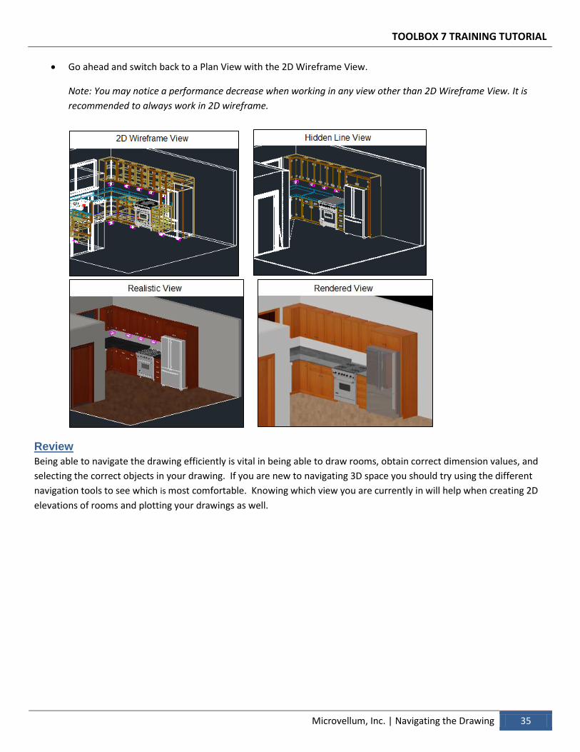
Go ahead and switch back to a Plan View with the 2D Wireframe View.
Note: You may notice a performance decrease when working in any view other than 2D Wireframe View. It is
recommended to always work in 2D wireframe.
Review
Being able to navigate the drawing efficiently is vital in being able to draw rooms, obtain correct dimension values, and
selecting the correct objects in your drawing. If you are new to navigating 3D space you should try using the different
navigation tools to see which is most comfortable. Knowing which view you are currently in will help when creating 2D
elevations of rooms and plotting your drawings as well.
Section 5 – Modifying Products This chapter of the tutorial will show you how you can use the properties window to make many different types of changes to the products. Although there several options available inside each product, this chapter will take a look at some of the more common options.
Modifying Products Edit products placed in the drawing using the available cabinet properties.
Microvellum, Inc.
TOOLBOX 7 TRAINING TUTORIAL
Microvellum, Inc. | Modifying Products 37
> Modifying Products
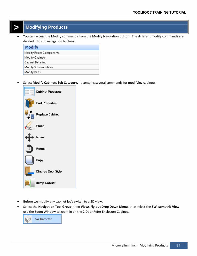
You can access the Modify commands from the Modify Navigation button. The different modify commands are
divided into sub navigation buttons.
Select Modify Cabinets Sub Category. It contains several commands for modifying cabinets.
Before we modify any cabinet let’s switch to a 3D view.
Select the Navigation Tool Group, then Views Fly-out Drop Down Menu, then select the SW Isometric View,
use the Zoom Window to zoom in on the 2 Door Refer Enclosure Cabinet.
TOOLBOX 7 TRAINING TUTORIAL
38 Modifying Products | Microvellum, Inc.
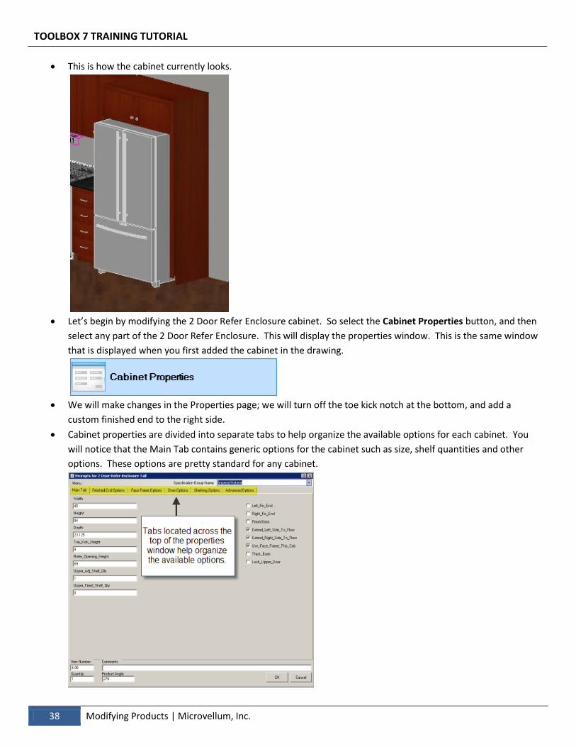
This is how the cabinet currently looks.
Let’s begin by modifying the 2 Door Refer Enclosure cabinet. So select the Cabinet Properties button, and then
select any part of the 2 Door Refer Enclosure. This will display the properties window. This is the same window
that is displayed when you first added the cabinet in the drawing.
We will make changes in the Properties page; we will turn off the toe kick notch at the bottom, and add a
custom finished end to the right side.
Cabinet properties are divided into separate tabs to help organize the available options for each cabinet. You
will notice that the Main Tab contains generic options for the cabinet such as size, shelf quantities and other
options. These options are pretty standard for any cabinet.
TOOLBOX 7 TRAINING TUTORIAL
Microvellum, Inc. | Modifying Products 39
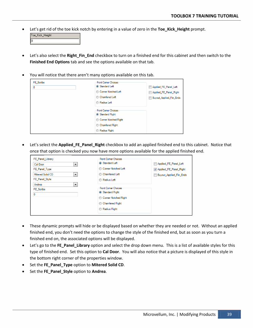
Let’s get rid of the toe kick notch by entering in a value of zero in the Toe_Kick_Height prompt.
Let’s also select the Right_Fin_End checkbox to turn on a finished end for this cabinet and then switch to the
Finished End Options tab and see the options available on that tab.
You will notice that there aren’t many options available on this tab.
Let’s select the Applied_FE_Panel_Right checkbox to add an applied finished end to this cabinet. Notice that
once that option is checked you now have more options available for the applied finished end.
These dynamic prompts will hide or be displayed based on whether they are needed or not. Without an applied
finished end, you don’t need the options to change the style of the finished end, but as soon as you turn a
finished end on, the associated options will be displayed.
Let’s go to the FE_Panel_Library option and select the drop down menu. This is a list of available styles for this
type of finished end. Set this option to Cal Door. You will also notice that a picture is displayed of this style in
the bottom right corner of the properties window.
Set the FE_Panel_Type option to Mitered Solid CD.
Set the FE_Panel_Style option to Andrea.
TOOLBOX 7 TRAINING TUTORIAL
40 Modifying Products | Microvellum, Inc.
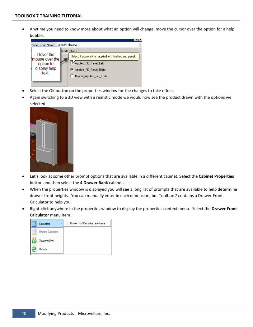
Anytime you need to know more about what an option will change, move the cursor over the option for a help
bubble.
Select the OK button on the properties window for the changes to take effect.
Again switching to a 3D view with a realistic mode we would now see the product drawn with the options we
selected.
Let’s look at some other prompt options that are available in a different cabinet. Select the Cabinet Properties
button and then select the 4 Drawer Bank cabinet.
When the properties window is displayed you will see a long list of prompts that are available to help determine
drawer front heights. You can manually enter in each dimension, but Toolbox 7 contains a Drawer Front
Calculator to help you.
Right-click anywhere in the properties window to display the properties context menu. Select the Drawer Front
Calculator menu item.
TOOLBOX 7 TRAINING TUTORIAL
Microvellum, Inc. | Modifying Products 41
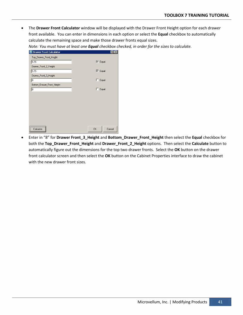
The Drawer Front Calculator window will be displayed with the Drawer Front Height option for each drawer
front available. You can enter in dimensions in each option or select the Equal checkbox to automatically
calculate the remaining space and make those drawer fronts equal sizes.
Note: You must have at least one Equal checkbox checked, in order for the sizes to calculate.
Enter in “8” for Drawer Front_3_Height and Bottom_Drawer_Front_Height then select the Equal checkbox for
both the Top_Drawer_Front_Height and Drawer_Front_2_Height options. Then select the Calculate button to
automatically figure out the dimensions for the top two drawer fronts. Select the OK button on the drawer
front calculator screen and then select the OK button on the Cabinet Properties interface to draw the cabinet
with the new drawer front sizes.
TOOLBOX 7 TRAINING TUTORIAL
42 Modifying Products | Microvellum, Inc.
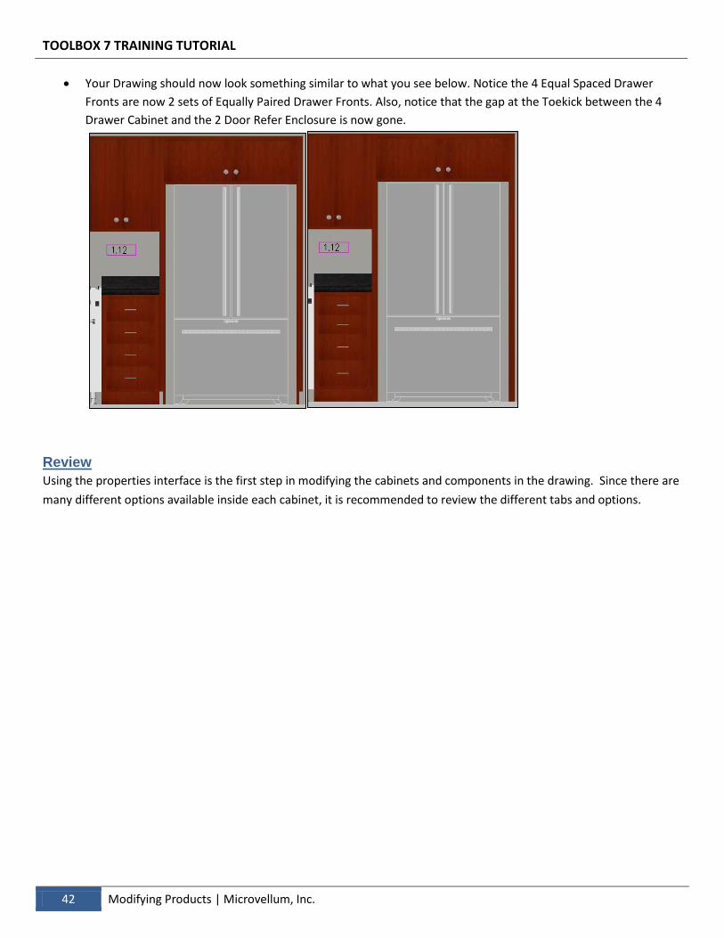
Your Drawing should now look something similar to what you see below. Notice the 4 Equal Spaced Drawer
Fronts are now 2 sets of Equally Paired Drawer Fronts. Also, notice that the gap at the Toekick between the 4
Drawer Cabinet and the 2 Door Refer Enclosure is now gone.
Review
Using the properties interface is the first step in modifying the cabinets and components in the drawing. Since there are
many different options available inside each cabinet, it is recommended to review the different tabs and options.
Section 6 – Creating a Custom Product Although the library contains a vast variety of products and the products contain a huge number of options there may be times when you need to create something more custom. This chapter will show you how to create a custom product from scratch using subassemblies.
Create a Custom Product Begin using the tools available in the library to design your own custom products.
Microvellum, Inc.
TOOLBOX 7 TRAINING TUTORIAL
44 Creating a Custom Product | Microvellum, Inc.
> Creating a Custom Product
For the purpose showing you how to create custom cabinets we are going to design them away from our room
so nothing will obstruct the view. We will later move this cabinet into place using the modify commands. Switch
to a Plan View, select the Navigation Tool Group, then Views Flyout Drop Down Menu, then select the Plan
View Button.
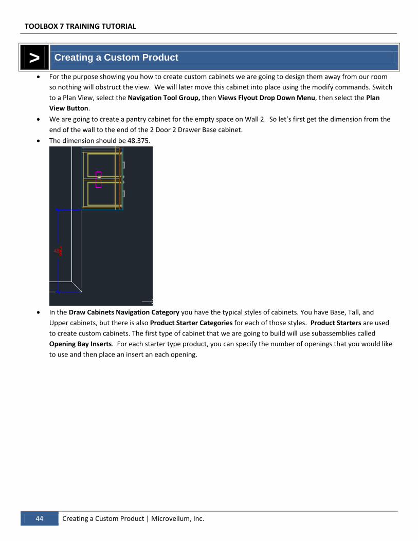
We are going to create a pantry cabinet for the empty space on Wall 2. So let’s first get the dimension from the
end of the wall to the end of the 2 Door 2 Drawer Base cabinet.
The dimension should be 48.375.
In the Draw Cabinets Navigation Category you have the typical styles of cabinets. You have Base, Tall, and
Upper cabinets, but there is also Product Starter Categories for each of those styles. Product Starters are used
to create custom cabinets. The first type of cabinet that we are going to build will use subassemblies called
Opening Bay Inserts. For each starter type product, you can specify the number of openings that you would like
to use and then place an insert an each opening.
TOOLBOX 7 TRAINING TUTORIAL
Microvellum, Inc. | Creating a Custom Product 45
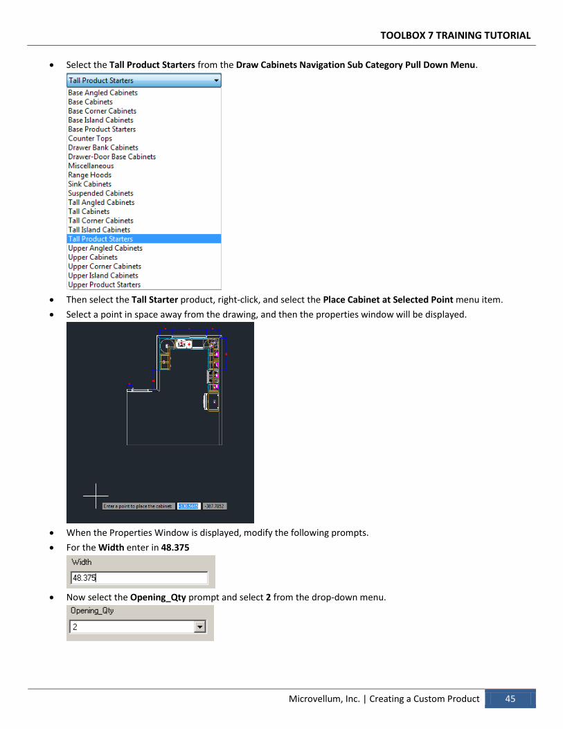
Select the Tall Product Starters from the Draw Cabinets Navigation Sub Category Pull Down Menu.
Then select the Tall Starter product, right-click, and select the Place Cabinet at Selected Point menu item.
Select a point in space away from the drawing, and then the properties window will be displayed.
When the Properties Window is displayed, modify the following prompts.
For the Width enter in 48.375
Now select the Opening_Qty prompt and select 2 from the drop-down menu.
TOOLBOX 7 TRAINING TUTORIAL
46 Creating a Custom Product | Microvellum, Inc.
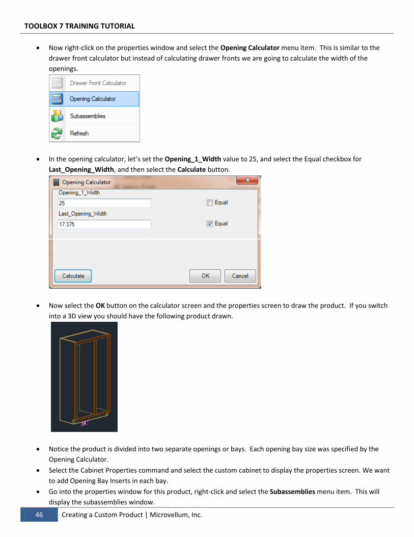
Now right-click on the properties window and select the Opening Calculator menu item. This is similar to the
drawer front calculator but instead of calculating drawer fronts we are going to calculate the width of the
openings.
In the opening calculator, let’s set the Opening_1_Width value to 25, and select the Equal checkbox for
Last_Opening_Width, and then select the Calculate button.
Now select the OK button on the calculator screen and the properties screen to draw the product. If you switch
into a 3D view you should have the following product drawn.
Notice the product is divided into two separate openings or bays. Each opening bay size was specified by the
Opening Calculator.
Select the Cabinet Properties command and select the custom cabinet to display the properties screen. We want
to add Opening Bay Inserts in each bay.
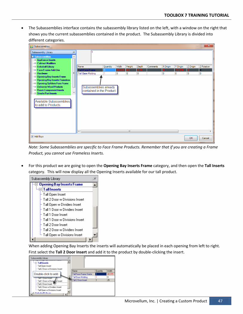
Go into the properties window for this product, right-click and select the Subassemblies menu item. This will
display the subassemblies window.
TOOLBOX 7 TRAINING TUTORIAL
Microvellum, Inc. | Creating a Custom Product 47
The Subassemblies interface contains the subassembly library listed on the left, with a window on the right that
shows you the current subassemblies contained in the product. The Subassembly Library is divided into
different categories.
Note: Some Subassemblies are specific to Face Frame Products. Remember that if you are creating a Frame
Product, you cannot use Frameless Inserts.
For this product we are going to open the Opening Bay Inserts Frame category, and then open the Tall Inserts
category. This will now display all the Opening Inserts available for our tall product.
When adding Opening Bay Inserts the inserts will automatically be placed in each opening from left to right.
First select the Tall 2 Door Insert and add it to the product by double-clicking the insert.
TOOLBOX 7 TRAINING TUTORIAL
48 Creating a Custom Product | Microvellum, Inc.
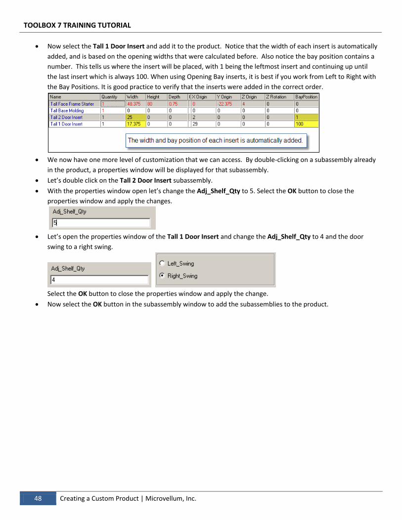
Now select the Tall 1 Door Insert and add it to the product. Notice that the width of each insert is automatically
added, and is based on the opening widths that were calculated before. Also notice the bay position contains a
number. This tells us where the insert will be placed, with 1 being the leftmost insert and continuing up until
the last insert which is always 100. When using Opening Bay inserts, it is best if you work from Left to Right with
the Bay Positions. It is good practice to verify that the inserts were added in the correct order.
We now have one more level of customization that we can access. By double-clicking on a subassembly already
in the product, a properties window will be displayed for that subassembly.
Let’s double click on the Tall 2 Door Insert subassembly.
With the properties window open let’s change the Adj_Shelf_Qty to 5. Select the OK button to close the
properties window and apply the changes.
Let’s open the properties window of the Tall 1 Door Insert and change the Adj_Shelf_Qty to 4 and the door
swing to a right swing.
Select the OK button to close the properties window and apply the change.
Now select the OK button in the subassembly window to add the subassemblies to the product.
TOOLBOX 7 TRAINING TUTORIAL
Microvellum, Inc. | Creating a Custom Product 49
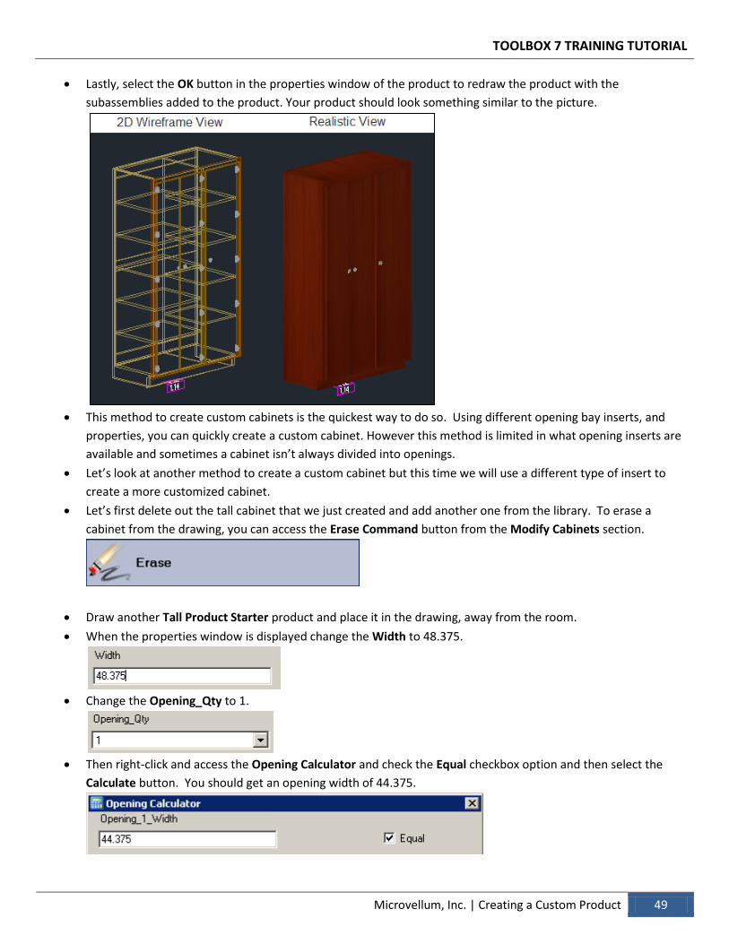
Lastly, select the OK button in the properties window of the product to redraw the product with the
subassemblies added to the product. Your product should look something similar to the picture.
This method to create custom cabinets is the quickest way to do so. Using different opening bay inserts, and
properties, you can quickly create a custom cabinet. However this method is limited in what opening inserts are
available and sometimes a cabinet isn’t always divided into openings.
Let’s look at another method to create a custom cabinet but this time we will use a different type of insert to
create a more customized cabinet.
Let’s first delete out the tall cabinet that we just created and add another one from the library. To erase a
cabinet from the drawing, you can access the Erase Command button from the Modify Cabinets section.
Draw another Tall Product Starter product and place it in the drawing, away from the room.
When the properties window is displayed change the Width to 48.375.
Change the Opening_Qty to 1.
Then right-click and access the Opening Calculator and check the Equal checkbox option and then select the
Calculate button. You should get an opening width of 44.375.
TOOLBOX 7 TRAINING TUTORIAL
50 Creating a Custom Product | Microvellum, Inc.
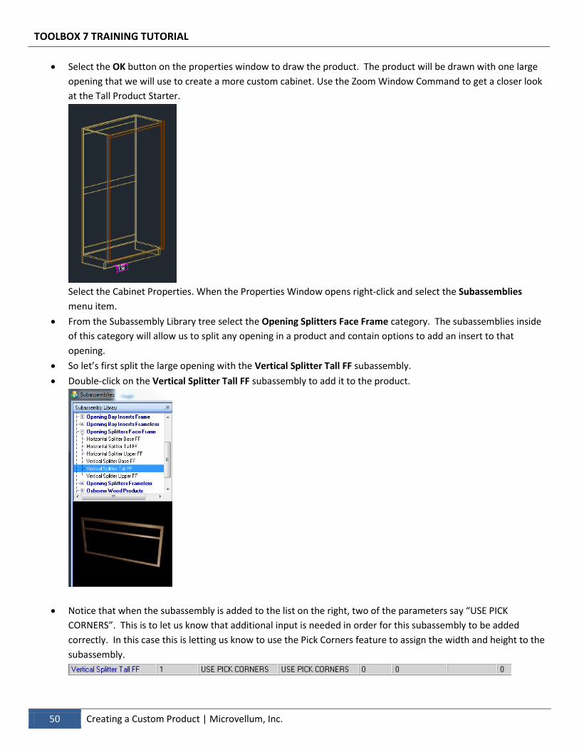
Select the OK button on the properties window to draw the product. The product will be drawn with one large
opening that we will use to create a more custom cabinet. Use the Zoom Window Command to get a closer look
at the Tall Product Starter.
Select the Cabinet Properties. When the Properties Window opens right-click and select the Subassemblies
menu item.
From the Subassembly Library tree select the Opening Splitters Face Frame category. The subassemblies inside
of this category will allow us to split any opening in a product and contain options to add an insert to that
opening.
So let’s first split the large opening with the Vertical Splitter Tall FF subassembly.
Double-click on the Vertical Splitter Tall FF subassembly to add it to the product.
Notice that when the subassembly is added to the list on the right, two of the parameters say “USE PICK
CORNERS”. This is to let us know that additional input is needed in order for this subassembly to be added
correctly. In this case this is letting us know to use the Pick Corners feature to assign the width and height to the
subassembly.
TOOLBOX 7 TRAINING TUTORIAL
Microvellum, Inc. | Creating a Custom Product 51
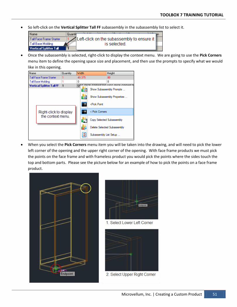
So left-click on the Vertical Splitter Tall FF subassembly in the subassembly list to select it.
Once the subassembly is selected, right-click to display the context menu. We are going to use the Pick Corners
menu item to define the opening space size and placement, and then use the prompts to specify what we would
like in this opening.
When you select the Pick Corners menu item you will be taken into the drawing, and will need to pick the lower
left corner of the opening and the upper right corner of the opening. With face frame products we must pick
the points on the face frame and with frameless product you would pick the points where the sides touch the
top and bottom parts. Please see the picture below for an example of how to pick the points on a face frame
product.
TOOLBOX 7 TRAINING TUTORIAL
52 Creating a Custom Product | Microvellum, Inc.
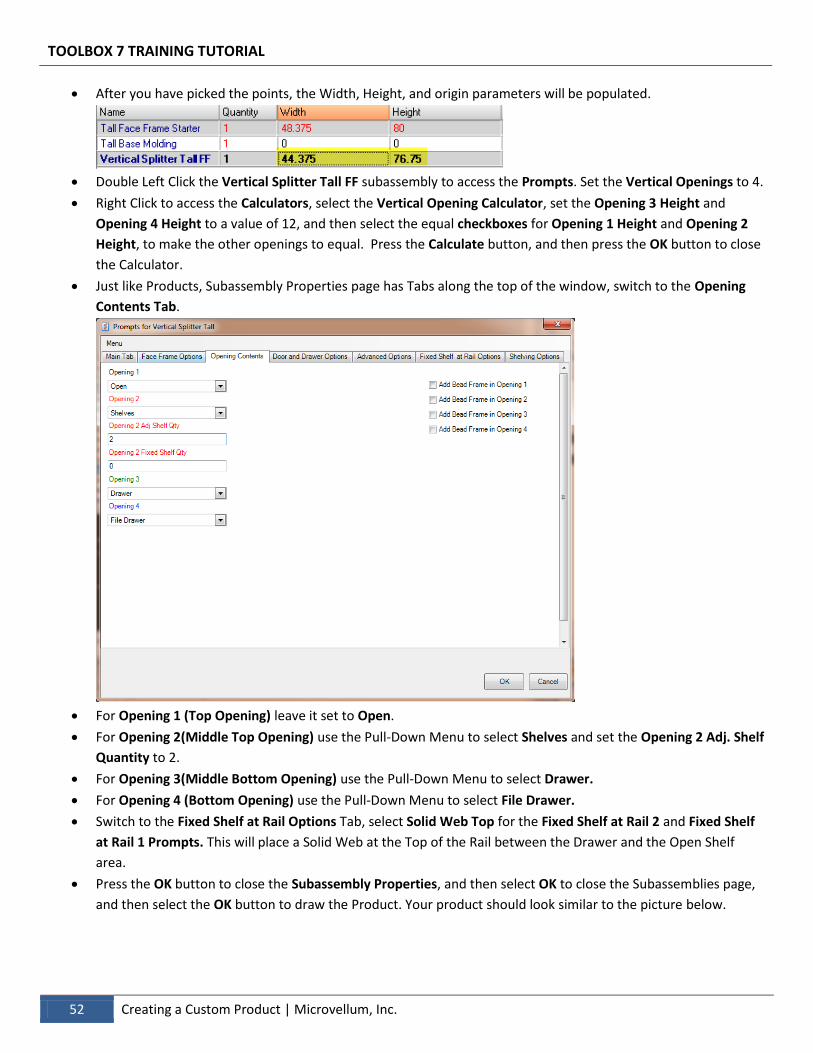
After you have picked the points, the Width, Height, and origin parameters will be populated.
Double Left Click the Vertical Splitter Tall FF subassembly to access the Prompts. Set the Vertical Openings to 4.
Right Click to access the Calculators, select the Vertical Opening Calculator, set the Opening 3 Height and
Opening 4 Height to a value of 12, and then select the equal checkboxes for Opening 1 Height and Opening 2
Height, to make the other openings to equal. Press the Calculate button, and then press the OK button to close
the Calculator.
Just like Products, Subassembly Properties page has Tabs along the top of the window, switch to the Opening
Contents Tab.
For Opening 1 (Top Opening) leave it set to Open.
For Opening 2(Middle Top Opening) use the Pull-Down Menu to select Shelves and set the Opening 2 Adj. Shelf
Quantity to 2.
For Opening 3(Middle Bottom Opening) use the Pull-Down Menu to select Drawer.
For Opening 4 (Bottom Opening) use the Pull-Down Menu to select File Drawer.
Switch to the Fixed Shelf at Rail Options Tab, select Solid Web Top for the Fixed Shelf at Rail 2 and Fixed Shelf
at Rail 1 Prompts. This will place a Solid Web at the Top of the Rail between the Drawer and the Open Shelf
area.
Press the OK button to close the Subassembly Properties, and then select OK to close the Subassemblies page,
and then select the OK button to draw the Product. Your product should look similar to the picture below.
TOOLBOX 7 TRAINING TUTORIAL
Microvellum, Inc. | Creating a Custom Product 53
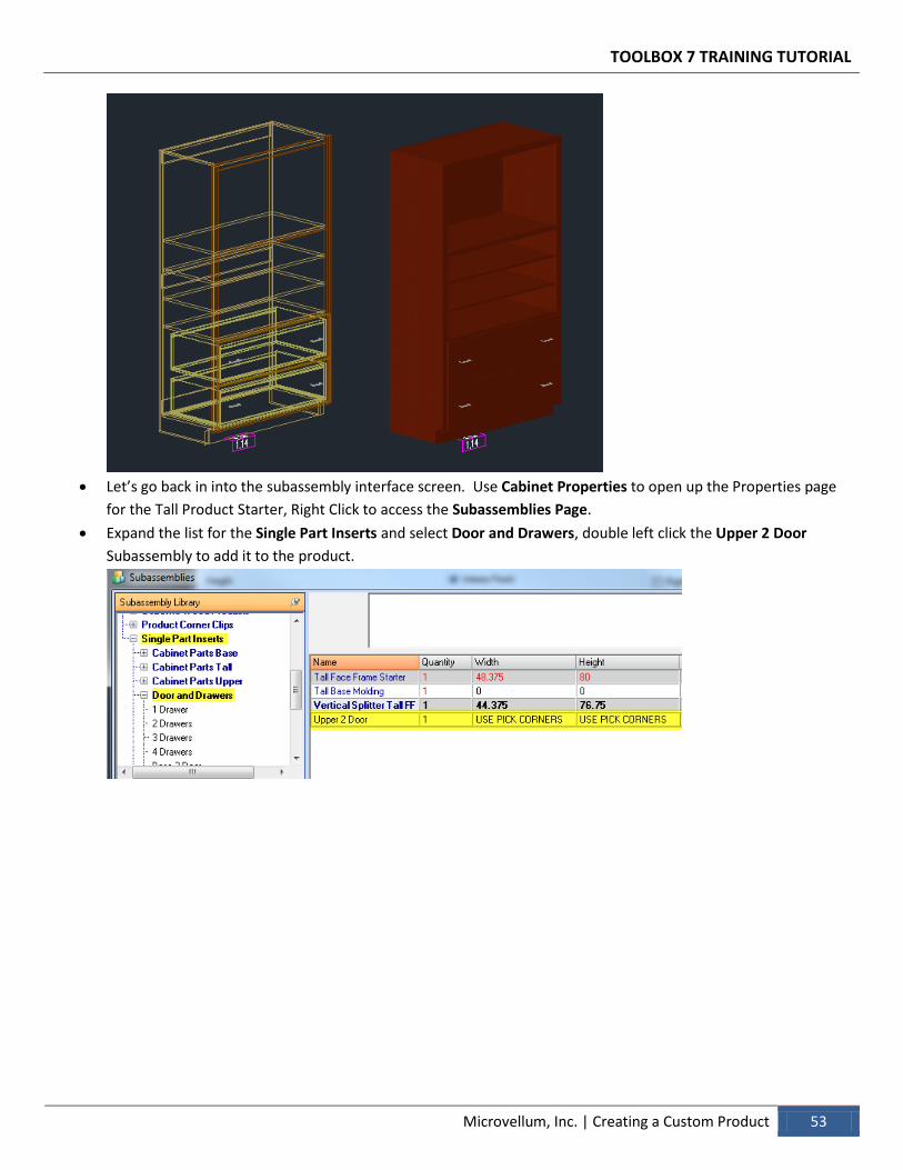
Let’s go back in into the subassembly interface screen. Use Cabinet Properties to open up the Properties page
for the Tall Product Starter, Right Click to access the Subassemblies Page.
Expand the list for the Single Part Inserts and select Door and Drawers, double left click the Upper 2 Door
Subassembly to add it to the product.
TOOLBOX 7 TRAINING TUTORIAL
54 Creating a Custom Product | Microvellum, Inc.
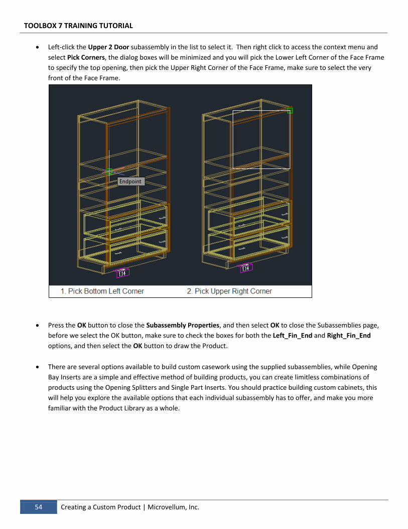
Left-click the Upper 2 Door subassembly in the list to select it. Then right click to access the context menu and
select Pick Corners, the dialog boxes will be minimized and you will pick the Lower Left Corner of the Face Frame
to specify the top opening, then pick the Upper Right Corner of the Face Frame, make sure to select the very
front of the Face Frame.
Press the OK button to close the Subassembly Properties, and then select OK to close the Subassemblies page,
before we select the OK button, make sure to check the boxes for both the Left_Fin_End and Right_Fin_End
options, and then select the OK button to draw the Product.
There are several options available to build custom casework using the supplied subassemblies, while Opening
Bay Inserts are a simple and effective method of building products, you can create limitless combinations of
products using the Opening Splitters and Single Part Inserts. You should practice building custom cabinets, this
will help you explore the available options that each individual subassembly has to offer, and make you more
familiar with the Product Library as a whole.
TOOLBOX 7 TRAINING TUTORIAL
Microvellum, Inc. | Creating a Custom Product 55
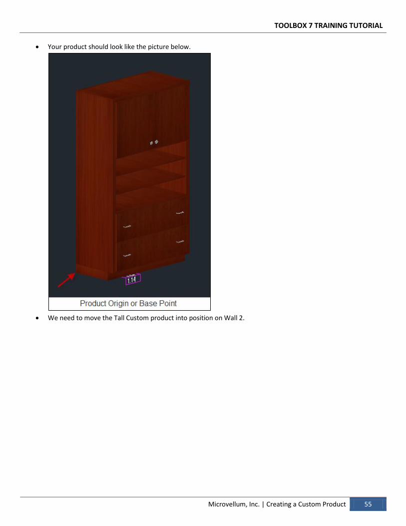
Your product should look like the picture below.
We need to move the Tall Custom product into position on Wall 2.
TOOLBOX 7 TRAINING TUTORIAL
56 Creating a Custom Product | Microvellum, Inc.
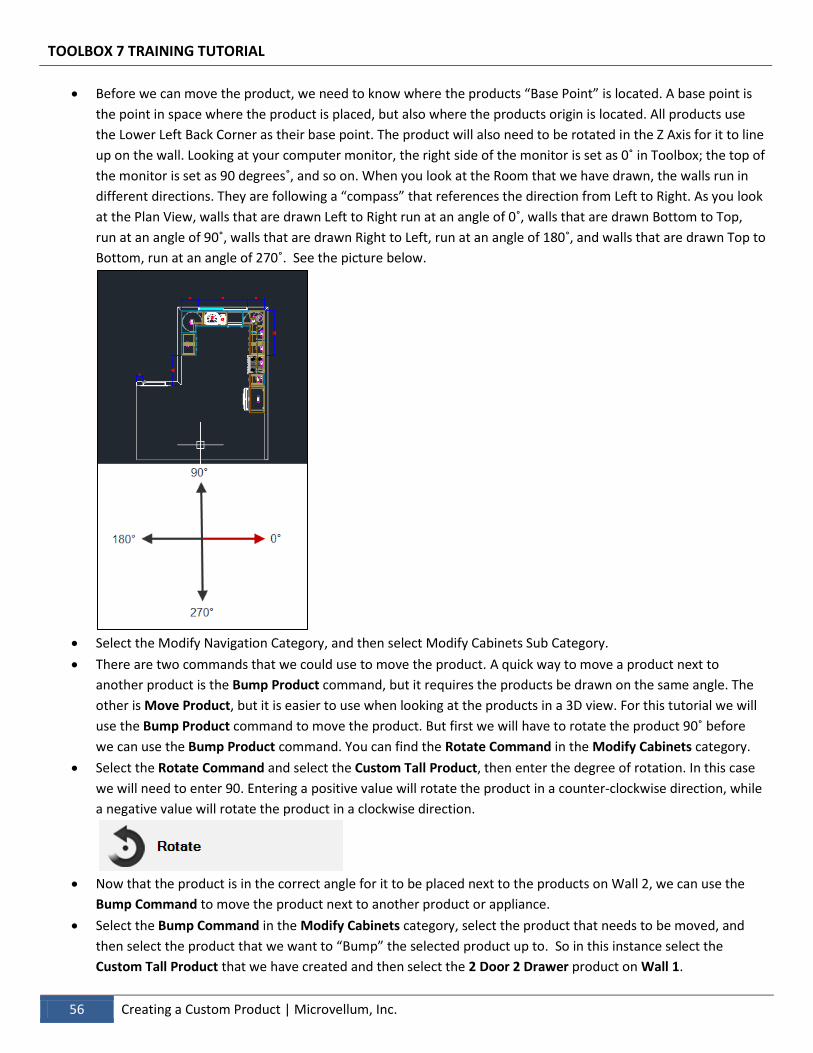
Before we can move the product, we need to know where the products “Base Point” is located. A base point is
the point in space where the product is placed, but also where the products origin is located. All products use
the Lower Left Back Corner as their base point. The product will also need to be rotated in the Z Axis for it to line
up on the wall. Looking at your computer monitor, the right side of the monitor is set as 0˚ in Toolbox; the top of
the monitor is set as 90 degrees˚, and so on. When you look at the Room that we have drawn, the walls run in
different directions. They are following a “compass” that references the direction from Left to Right. As you look
at the Plan View, walls that are drawn Left to Right run at an angle of 0˚, walls that are drawn Bottom to Top,
run at an angle of 90˚, walls that are drawn Right to Left, run at an angle of 180˚, and walls that are drawn Top to
Bottom, run at an angle of 270˚. See the picture below.
Select the Modify Navigation Category, and then select Modify Cabinets Sub Category.
There are two commands that we could use to move the product. A quick way to move a product next to
another product is the Bump Product command, but it requires the products be drawn on the same angle. The
other is Move Product, but it is easier to use when looking at the products in a 3D view. For this tutorial we will
use the Bump Product command to move the product. But first we will have to rotate the product 90˚ before
we can use the Bump Product command. You can find the Rotate Command in the Modify Cabinets category.
Select the Rotate Command and select the Custom Tall Product, then enter the degree of rotation. In this case
we will need to enter 90. Entering a positive value will rotate the product in a counter-clockwise direction, while
a negative value will rotate the product in a clockwise direction.
Now that the product is in the correct angle for it to be placed next to the products on Wall 2, we can use the
Bump Command to move the product next to another product or appliance.
Select the Bump Command in the Modify Cabinets category, select the product that needs to be moved, and
then select the product that we want to “Bump” the selected product up to. So in this instance select the
Custom Tall Product that we have created and then select the 2 Door 2 Drawer product on Wall 1.
TOOLBOX 7 TRAINING TUTORIAL
Microvellum, Inc. | Creating a Custom Product 57
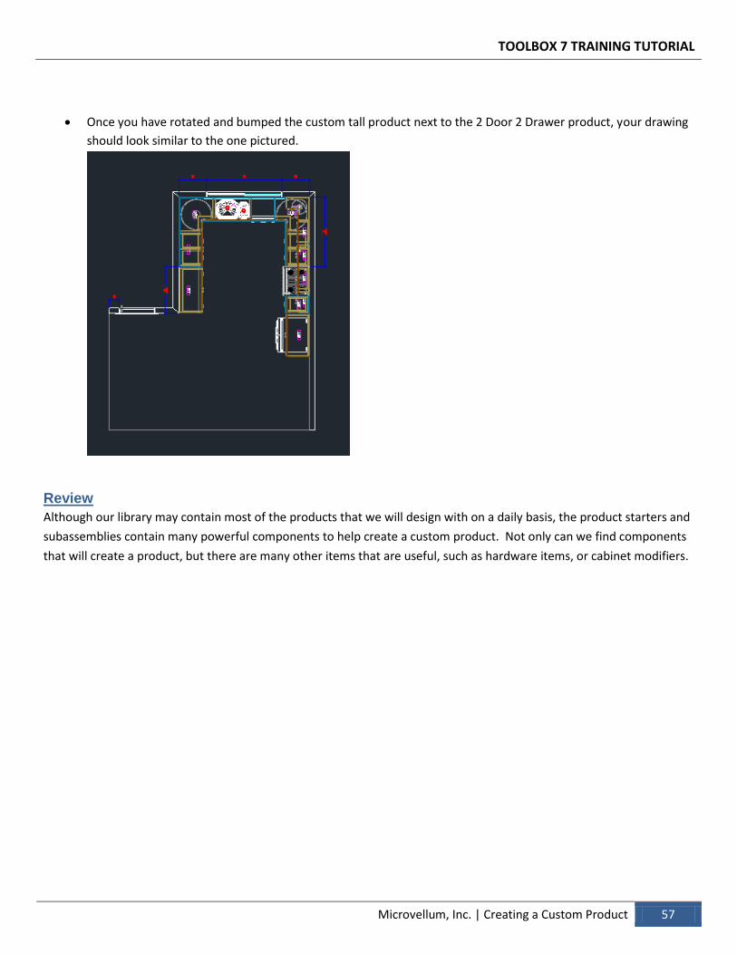
Once you have rotated and bumped the custom tall product next to the 2 Door 2 Drawer product, your drawing
should look similar to the one pictured.
Review
Although our library may contain most of the products that we will design with on a daily basis, the product starters and
subassemblies contain many powerful components to help create a custom product. Not only can we find components
that will create a product, but there are many other items that are useful, such as hardware items, or cabinet modifiers.
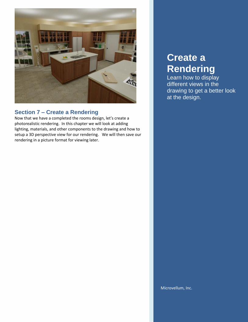
Section 7 – Create a Rendering Now that we have a completed the rooms design, let’s create a photorealistic rendering. In this chapter we will look at adding lighting, materials, and other components to the drawing and how to setup a 3D perspective view for our rendering. We will then save our rendering in a picture format for viewing later.
Create a Rendering Learn how to display different views in the drawing to get a better look at the design.
Microvellum, Inc.
TOOLBOX 7 TRAINING TUTORIAL
Microvellum, Inc. | Create a Rendering 59
> Create a Rendering
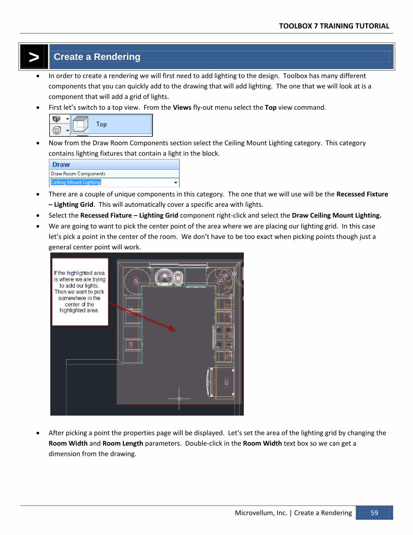
In order to create a rendering we will first need to add lighting to the design. Toolbox has many different
components that you can quickly add to the drawing that will add lighting. The one that we will look at is a
component that will add a grid of lights.
First let’s switch to a top view. From the Views fly-out menu select the Top view command.
Now from the Draw Room Components section select the Ceiling Mount Lighting category. This category
contains lighting fixtures that contain a light in the block.
There are a couple of unique components in this category. The one that we will use will be the Recessed Fixture
– Lighting Grid. This will automatically cover a specific area with lights.
Select the Recessed Fixture – Lighting Grid component right-click and select the Draw Ceiling Mount Lighting.
We are going to want to pick the center point of the area where we are placing our lighting grid. In this case
let’s pick a point in the center of the room. We don’t have to be too exact when picking points though just a
general center point will work.
After picking a point the properties page will be displayed. Let’s set the area of the lighting grid by changing the
Room Width and Room Length parameters. Double-click in the Room Width text box so we can get a
dimension from the drawing.
TOOLBOX 7 TRAINING TUTORIAL
60 Create a Rendering | Microvellum, Inc.
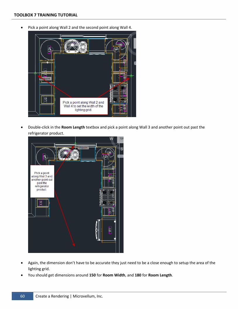
Pick a point along Wall 2 and the second point along Wall 4.
Double-click in the Room Length textbox and pick a point along Wall 3 and another point out past the
refrigerator product.
Again, the dimension don’t have to be accurate they just need to be a close enough to setup the area of the
lighting grid.
You should get dimensions around 150 for Room Width, and 180 for Room Length.
TOOLBOX 7 TRAINING TUTORIAL
Microvellum, Inc. | Create a Rendering 61
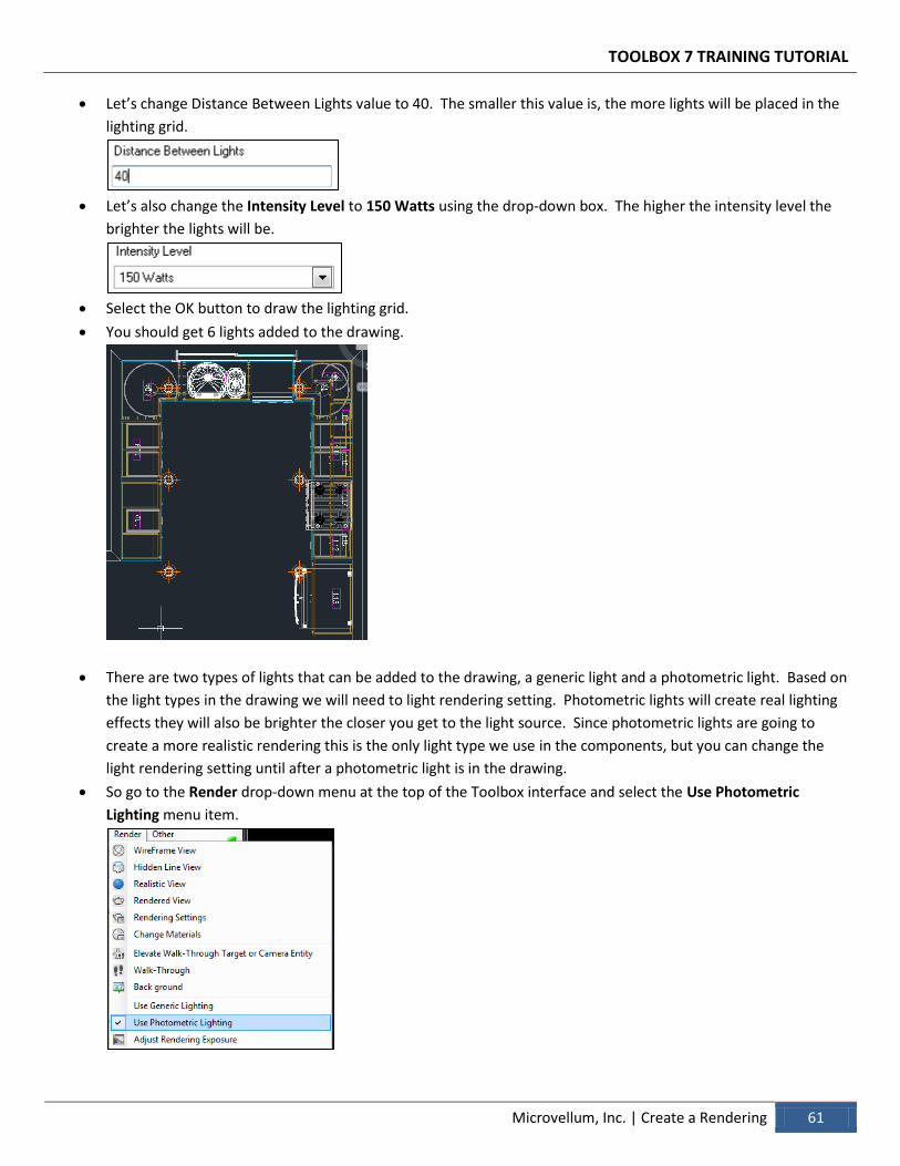
Let’s change Distance Between Lights value to 40. The smaller this value is, the more lights will be placed in the
lighting grid.
Let’s also change the Intensity Level to 150 Watts using the drop-down box. The higher the intensity level the
brighter the lights will be.
Select the OK button to draw the lighting grid.
You should get 6 lights added to the drawing.
There are two types of lights that can be added to the drawing, a generic light and a photometric light. Based on
the light types in the drawing we will need to light rendering setting. Photometric lights will create real lighting
effects they will also be brighter the closer you get to the light source. Since photometric lights are going to
create a more realistic rendering this is the only light type we use in the components, but you can change the
light rendering setting until after a photometric light is in the drawing.
So go to the Render drop-down menu at the top of the Toolbox interface and select the Use Photometric
Lighting menu item.
TOOLBOX 7 TRAINING TUTORIAL
62 Create a Rendering | Microvellum, Inc.
Lighting is a very important part of getting a rending to look as realistic as possible. If you are going to be
creating a lot of presentation renderings it is recommended to try using all the different lighting fixtures and
settings so you can get a better understanding of how many lights you might need for a room.
To help bring your rendering to life you can use the Furniture and Accessories components to add more objects
into your drawing.
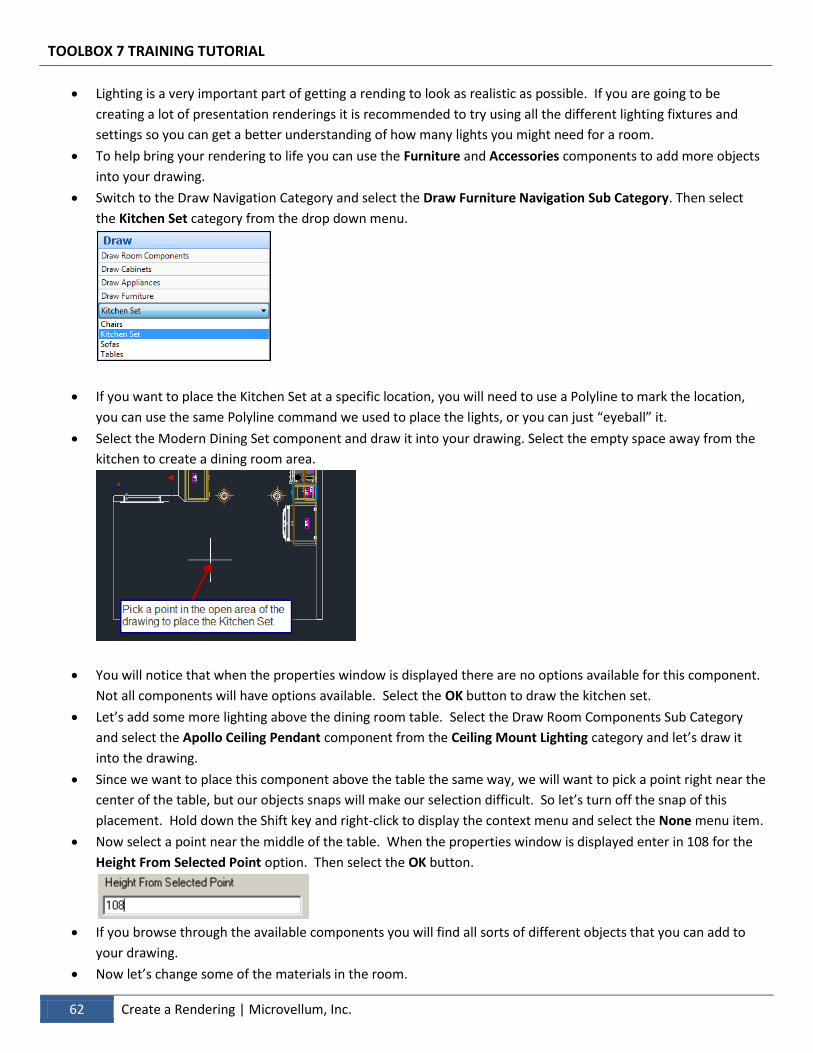
Switch to the Draw Navigation Category and select the Draw Furniture Navigation Sub Category. Then select
the Kitchen Set category from the drop down menu.
If you want to place the Kitchen Set at a specific location, you will need to use a Polyline to mark the location,
you can use the same Polyline command we used to place the lights, or you can just “eyeball” it.
Select the Modern Dining Set component and draw it into your drawing. Select the empty space away from the
kitchen to create a dining room area.
You will notice that when the properties window is displayed there are no options available for this component.
Not all components will have options available. Select the OK button to draw the kitchen set.
Let’s add some more lighting above the dining room table. Select the Draw Room Components Sub Category
and select the Apollo Ceiling Pendant component from the Ceiling Mount Lighting category and let’s draw it
into the drawing.
Since we want to place this component above the table the same way, we will want to pick a point right near the
center of the table, but our objects snaps will make our selection difficult. So let’s turn off the snap of this
placement. Hold down the Shift key and right-click to display the context menu and select the None menu item.
Now select a point near the middle of the table. When the properties window is displayed enter in 108 for the
Height From Selected Point option. Then select the OK button.
If you browse through the available components you will find all sorts of different objects that you can add to
your drawing.
Now let’s change some of the materials in the room.
TOOLBOX 7 TRAINING TUTORIAL
Microvellum, Inc. | Create a Rendering 63
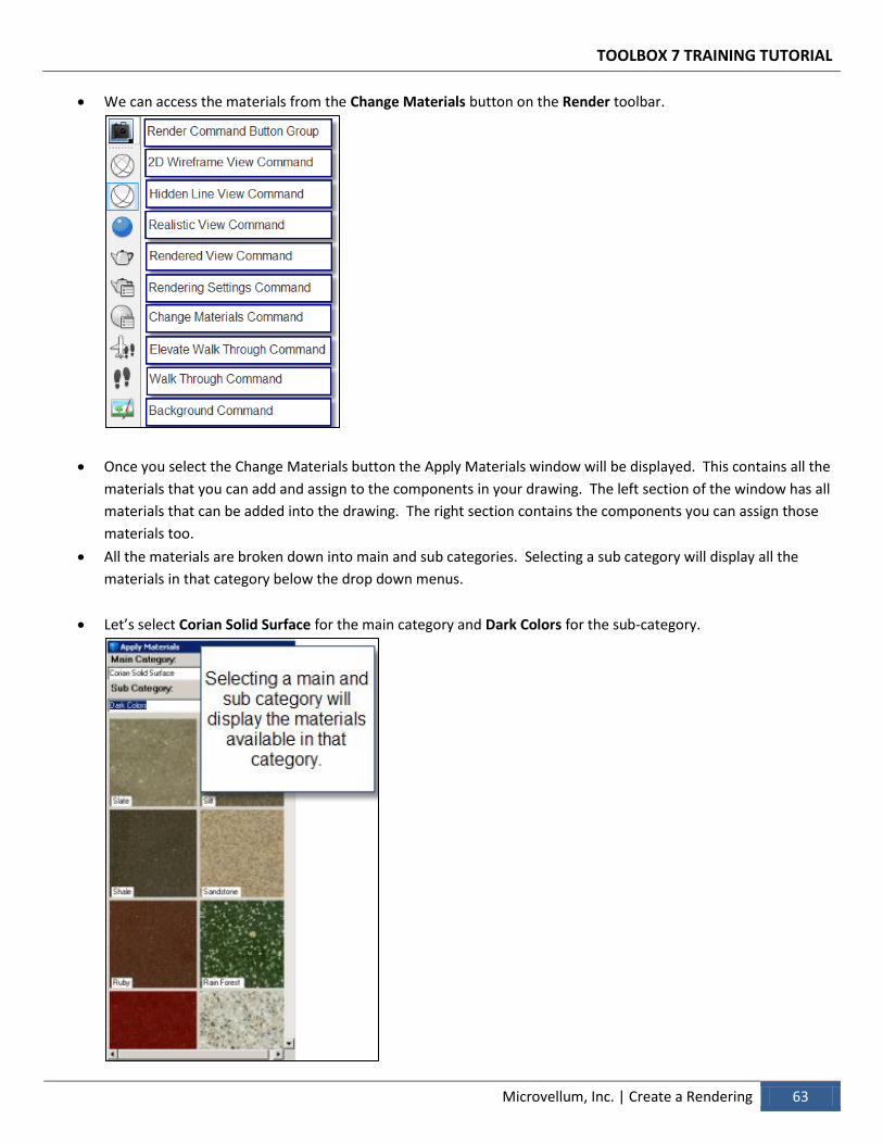
We can access the materials from the Change Materials button on the Render toolbar.
Once you select the Change Materials button the Apply Materials window will be displayed. This contains all the
materials that you can add and assign to the components in your drawing. The left section of the window has all
materials that can be added into the drawing. The right section contains the components you can assign those
materials too.
All the materials are broken down into main and sub categories. Selecting a sub category will display all the
materials in that category below the drop down menus.
Let’s select Corian Solid Surface for the main category and Dark Colors for the sub-category.
TOOLBOX 7 TRAINING TUTORIAL
64 Create a Rendering | Microvellum, Inc.
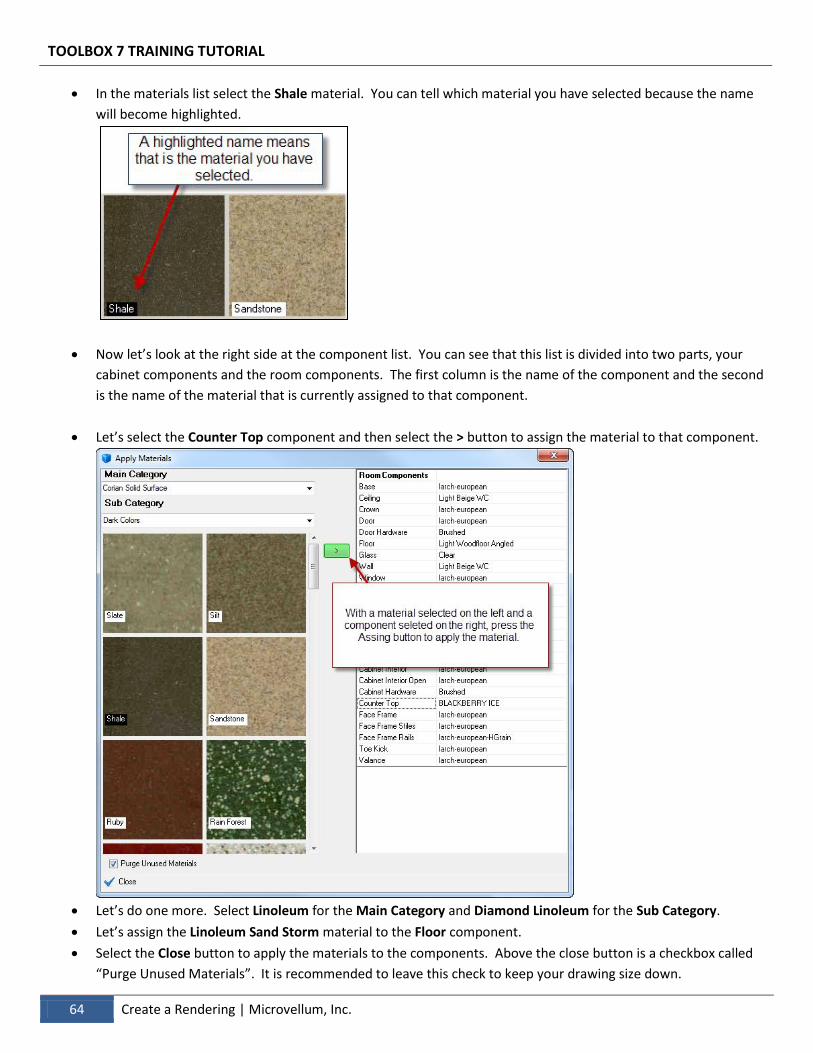
In the materials list select the Shale material. You can tell which material you have selected because the name
will become highlighted.
Now let’s look at the right side at the component list. You can see that this list is divided into two parts, your
cabinet components and the room components. The first column is the name of the component and the second
is the name of the material that is currently assigned to that component.
Let’s select the Counter Top component and then select the > button to assign the material to that component.
Let’s do one more. Select Linoleum for the Main Category and Diamond Linoleum for the Sub Category.
Let’s assign the Linoleum Sand Storm material to the Floor component.
Select the Close button to apply the materials to the components. Above the close button is a checkbox called
“Purge Unused Materials”. It is recommended to leave this check to keep your drawing size down.
TOOLBOX 7 TRAINING TUTORIAL
Microvellum, Inc. | Create a Rendering 65
The Apply Materials window allows control over most of the components in a drawing, but you will also find
some material selections from the properties window of the component. For example, most appliances will
allow you to change the color from their properties window when you are placing the component.
Now that we have added lighting and changed materials, let’s setup the view that we want to capture in the
rendering. This is best done with the Perspective View command from the Navigate Toolbar.
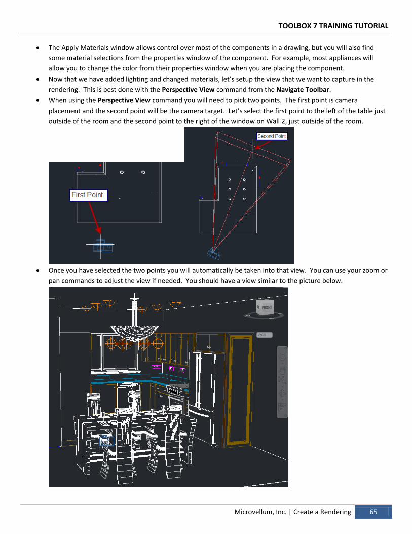
When using the Perspective View command you will need to pick two points. The first point is camera
placement and the second point will be the camera target. Let’s select the first point to the left of the table just
outside of the room and the second point to the right of the window on Wall 2, just outside of the room.
Once you have selected the two points you will automatically be taken into that view. You can use your zoom or
pan commands to adjust the view if needed. You should have a view similar to the picture below.

TOOLBOX 7 TRAINING TUTORIAL
66 Create a Rendering | Microvellum, Inc.
Now that we have the lighting, materials, and view ready, we can render our scene. There are preset levels of
that you can adjust, to determine how detailed the rendering will be. Since this is the first render and we don’t
know how the lighting or materials will look let’s adjust this rendering setting to a lower quality and faster
render time.
Select the Rendering Settings command
from the Render toolbar. This will display the rendering settings window. At the top is a drop-down box with
preset rendering qualities. Let’s set this option to Medium. Then select the “X” in the Upper Left Window, to
close the Rendering Settings.
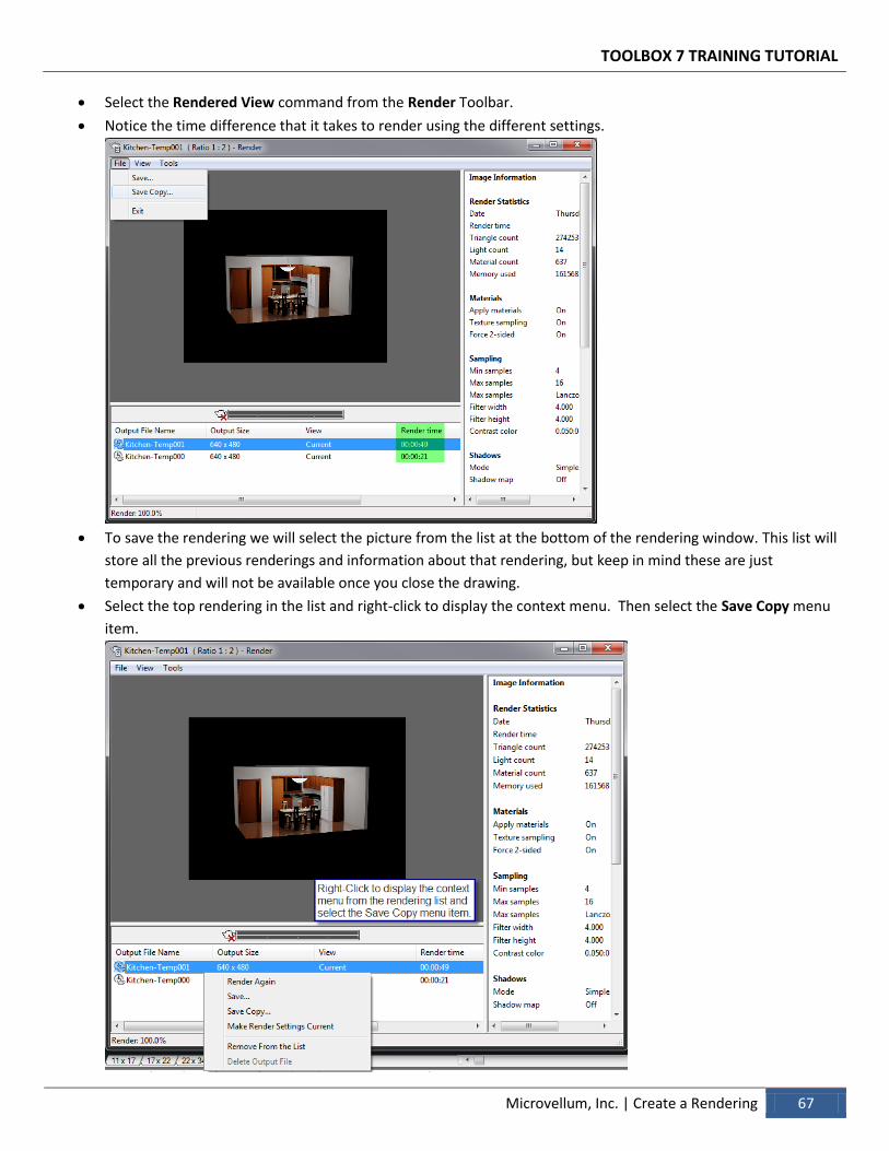
Now let’s select the Rendered View command from the Render Toolbar.
It is recommended to render with the Medium setting until you are happy with the scene. This will save time on
each render to ensure that the correct lighting, materials, and objects are setup.
Compare the Renderings below, one is rendered with Medium Render Presets and the other done with
Presentation Render Presets. The presentation rendering will render a sharper and look better.
Once you are happy with the scene you can switch the Rendering Settings to High or Presentation to create a
crisper looking picture.
Select the Rendering Settings command from the Render toolbar.
Set the Rendering Settings to High or Presentation from the drop down menu. Then select the “X” in the Upper
Left Window, to close the Rendering Settings.
TOOLBOX 7 TRAINING TUTORIAL
Microvellum, Inc. | Create a Rendering 67
Select the Rendered View command from the Render Toolbar.
Notice the time difference that it takes to render using the different settings.
To save the rendering we will select the picture from the list at the bottom of the rendering window. This list will
store all the previous renderings and information about that rendering, but keep in mind these are just
temporary and will not be available once you close the drawing.
Select the top rendering in the list and right-click to display the context menu. Then select the Save Copy menu
item.
TOOLBOX 7 TRAINING TUTORIAL
68 Create a Rendering | Microvellum, Inc.
Now give your picture a name and select where you would like to save it on your computer to save.
Review
This chapter has shown us how to add lighting into the drawing, change materials, and setup a view to render. The
tools that Toolbox 7 provides make it very simple to create photo-like renderings in a short amount of time. It is
important to light your scene correctly as this will be a major factor in how the rendering looks. It is also good
practice to find materials that work well together.
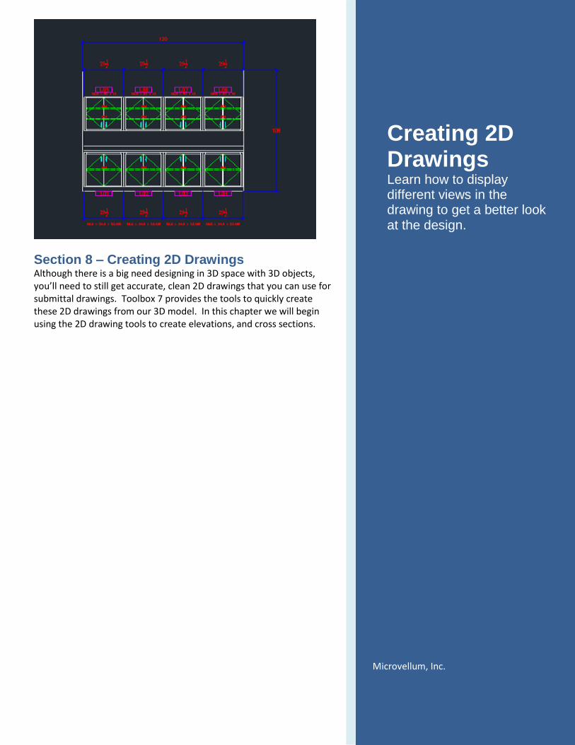
Section 8 – Creating 2D Drawings Although there is a big need designing in 3D space with 3D objects, you’ll need to still get accurate, clean 2D drawings that you can use for submittal drawings. Toolbox 7 provides the tools to quickly create these 2D drawings from our 3D model. In this chapter we will begin using the 2D drawing tools to create elevations, and cross sections.
Creating 2D Drawings Learn how to display different views in the drawing to get a better look at the design.
Microvellum, Inc.
TOOLBOX 7 TRAINING TUTORIAL
70 Creating 2D Drawings | Microvellum, Inc.
> Creating 2D Drawings
Select the Draw navigation button
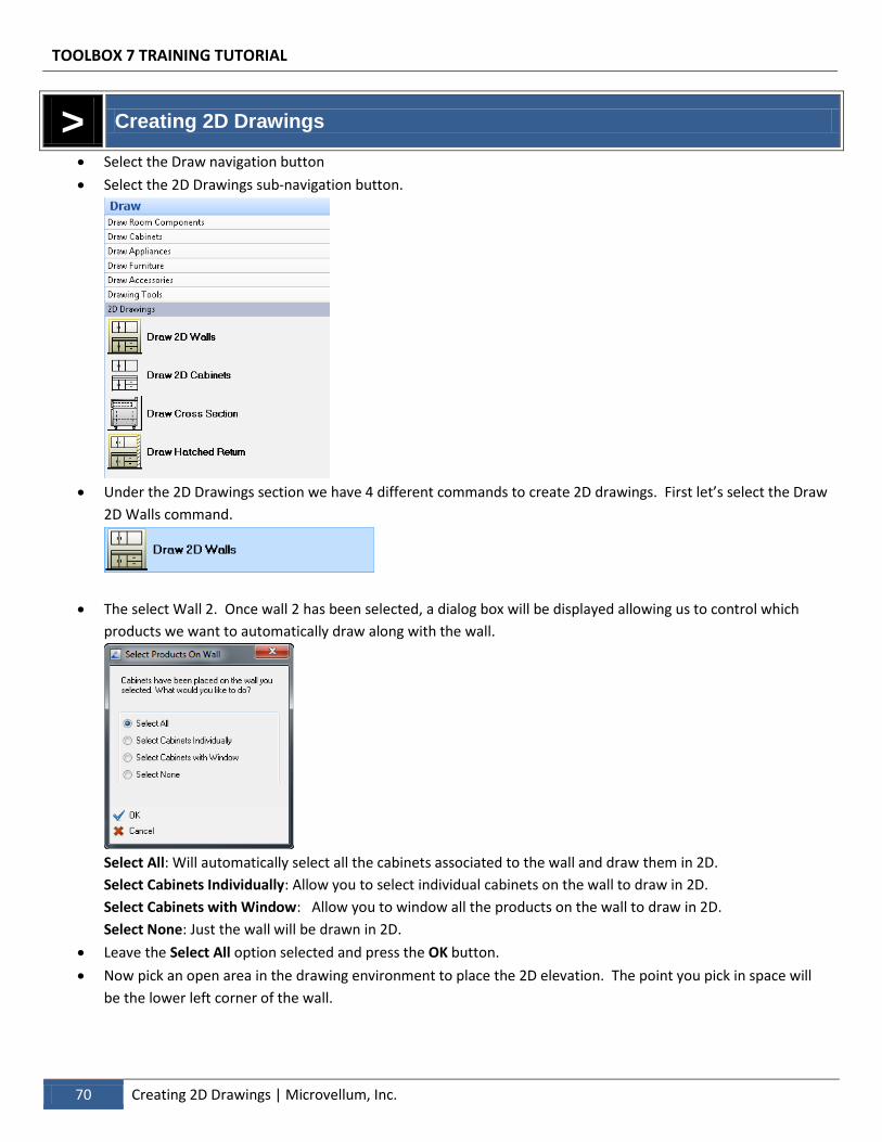
Select the 2D Drawings sub-navigation button.
Under the 2D Drawings section we have 4 different commands to create 2D drawings. First let’s select the Draw
2D Walls command.
The select Wall 2. Once wall 2 has been selected, a dialog box will be displayed allowing us to control which
products we want to automatically draw along with the wall.
Select All: Will automatically select all the cabinets associated to the wall and draw them in 2D.
Select Cabinets Individually: Allow you to select individual cabinets on the wall to draw in 2D.
Select Cabinets with Window: Allow you to window all the products on the wall to draw in 2D.
Select None: Just the wall will be drawn in 2D.
Leave the Select All option selected and press the OK button.
Now pick an open area in the drawing environment to place the 2D elevation. The point you pick in space will
be the lower left corner of the wall.
TOOLBOX 7 TRAINING TUTORIAL
Microvellum, Inc. | Creating 2D Drawings 71
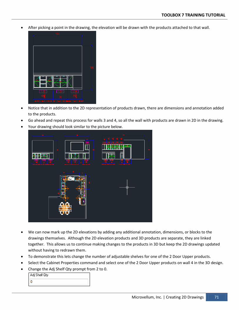
After picking a point in the drawing, the elevation will be drawn with the products attached to that wall.
Notice that in addition to the 2D representation of products drawn, there are dimensions and annotation added
to the products.
Go ahead and repeat this process for walls 3 and 4, so all the wall with products are drawn in 2D in the drawing.
Your drawing should look similar to the picture below.
We can now mark up the 2D elevations by adding any additional annotation, dimensions, or blocks to the
drawings themselves. Although the 2D elevation products and 3D products are separate, they are linked
together. This allows us to continue making changes to the products in 3D but keep the 2D drawings updated
without having to redrawn them.
To demonstrate this lets change the number of adjustable shelves for one of the 2 Door Upper products.
Select the Cabinet Properties command and select one of the 2 Door Upper products on wall 4 in the 3D design.
Change the Adj Shelf Qty prompt from 2 to 0.
TOOLBOX 7 TRAINING TUTORIAL
72 Creating 2D Drawings | Microvellum, Inc.
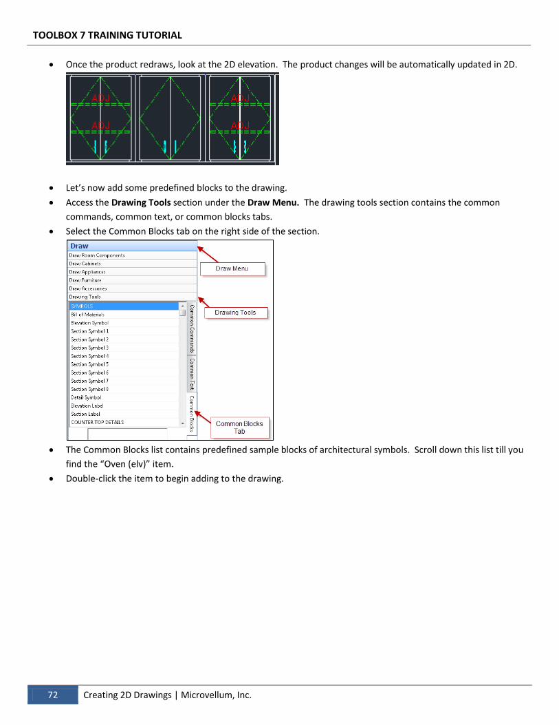
Once the product redraws, look at the 2D elevation. The product changes will be automatically updated in 2D.
Let’s now add some predefined blocks to the drawing.
Access the Drawing Tools section under the Draw Menu. The drawing tools section contains the common
commands, common text, or common blocks tabs.
Select the Common Blocks tab on the right side of the section.
The Common Blocks list contains predefined sample blocks of architectural symbols. Scroll down this list till you
find the “Oven (elv)” item.
Double-click the item to begin adding to the drawing.
TOOLBOX 7 TRAINING TUTORIAL
Microvellum, Inc. | Creating 2D Drawings 73
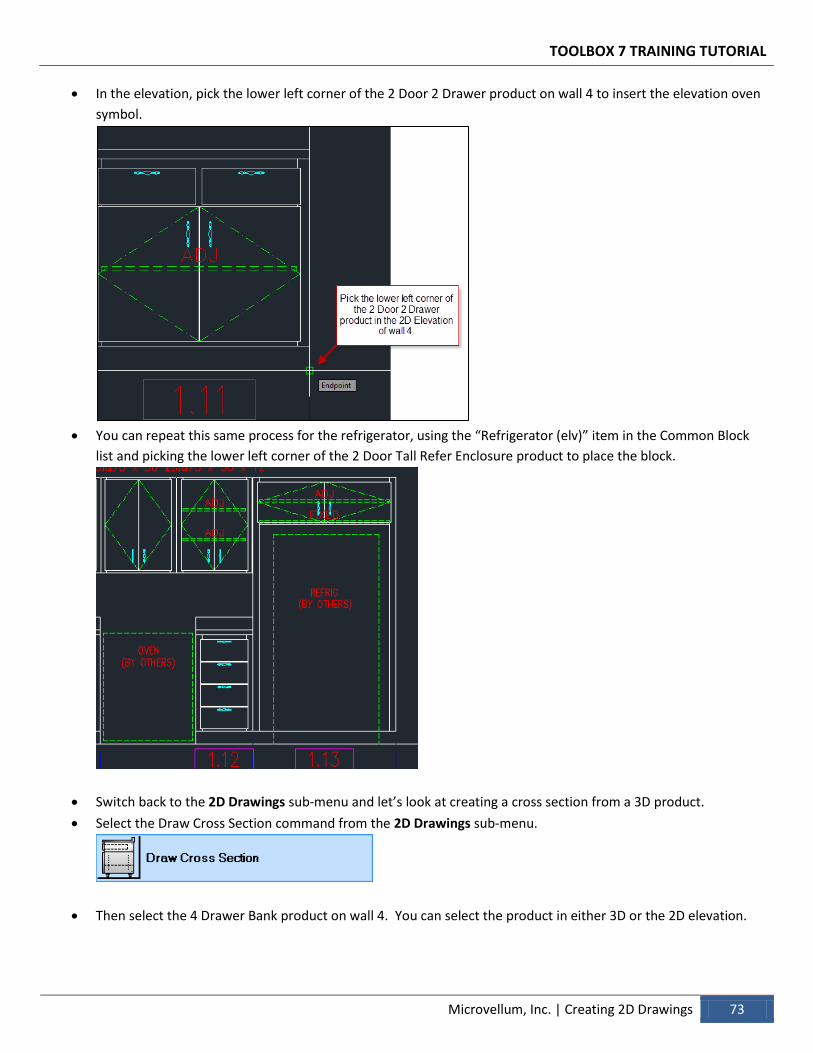
In the elevation, pick the lower left corner of the 2 Door 2 Drawer product on wall 4 to insert the elevation oven
symbol.
You can repeat this same process for the refrigerator, using the “Refrigerator (elv)” item in the Common Block
list and picking the lower left corner of the 2 Door Tall Refer Enclosure product to place the block.
Switch back to the 2D Drawings sub-menu and let’s look at creating a cross section from a 3D product.
Select the Draw Cross Section command from the 2D Drawings sub-menu.
Then select the 4 Drawer Bank product on wall 4. You can select the product in either 3D or the 2D elevation.
TOOLBOX 7 TRAINING TUTORIAL
74 Creating 2D Drawings | Microvellum, Inc.
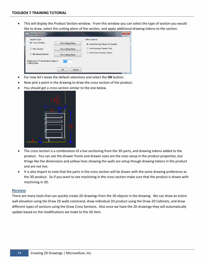
This will display the Product Section window. From this window you can select the type of section you would
like to draw, select the cutting plane of the section, and apply additional drawing tokens to the section.
For now let’s leave the default selections and select the OK button.
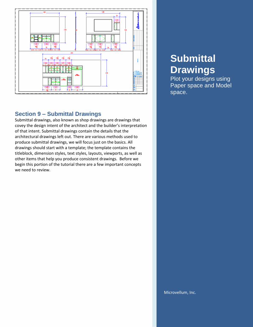
Now pick a point in the drawing to draw the cross section of the product.
You should get a cross section similar to the one below.
The cross section is a combination of a live sectioning from the 3D parts, and drawing tokens added to the
product. You can see the drawer fronts and drawer sizes are the sizes setup in the product properties, but
things like the dimensions and yellow lines showing the walls are setup though drawing tokens in the product
and are not live.
It is also import to note that the parts in the cross section will be drawn with the same drawing preference as
the 3D product. So if you want to see machining in the cross section make sure that the product is drawn with
machining in 3D.
Review
There are many tools that can quickly create 2D drawings from the 3D objects in the drawing. We can draw an entire
wall elevation using the Draw 2D walls command, draw individual 2D product using the Draw 2D Cabinets, and draw
different types of sections using the Draw Cross Sections. Also once we have the 2D drawings they will automatically
update based on the modifications we make to the 3D item.
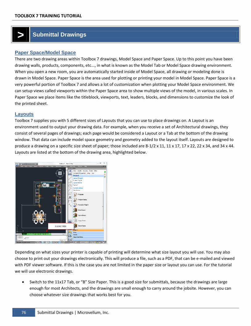
Section 9 – Submittal Drawings Submittal drawings, also known as shop drawings are drawings that covey the design intent of the architect and the builder’s interpretation of that intent. Submittal drawings contain the details that the architectural drawings left out. There are various methods used to produce submittal drawings, we will focus just on the basics. All drawings should start with a template; the template contains the titleblock, dimension styles, text styles, layouts, viewports, as well as other items that help you produce consistent drawings. Before we begin this portion of the tutorial there are a few important concepts we need to review.
Submittal Drawings Plot your designs using Paper space and Model space.
Microvellum, Inc.
TOOLBOX 7 TRAINING TUTORIAL
76 Submittal Drawings | Microvellum, Inc.
> Submittal Drawings
Paper Space/Model Space
There are two drawing areas within Toolbox 7 drawings, Model Space and Paper Space. Up to this point you have been
drawing walls, products, components, etc..., in what is known as the Model Tab or Model Space drawing environment.
When you open a new room, you are automatically started inside of Model Space, all drawing or modeling done is
drawn in Model Space. Paper Space is the area used for plotting or printing your model in Model Space. Paper Space is a
very powerful portion of Toolbox 7 and allows a lot of customization when plotting your Model Space environment. We
can setup views called viewports within the Paper Space area to show multiple views of the model, in various scales. In
Paper Space we place items like the titleblock, viewports, text, leaders, blocks, and dimensions to customize the look of
the printed sheet.
Layouts
Toolbox 7 supplies you with 5 different sizes of Layouts that you can use to place drawings on. A Layout is an
environment used to output your drawing data. For example, when you receive a set of Architectural drawings, they
consist of several pages of drawings; each page would be considered a Layout or a Tab at the bottom of the drawing
window. That data can include model space geometry and geometry added to the layout itself. Layouts are designed to
produce a drawing on a specific size sheet of paper; those included are 8-1/2 x 11, 11 x 17, 17 x 22, 22 x 34, and 34 x 44.
Layouts are listed at the bottom of the drawing area, highlighted below.
Depending on what sizes your printer is capable of printing will determine what size layout you will use. You may also
choose to print out your drawings electronically. This will produce a file, such as a PDF, that can be e-mailed and viewed
with PDF viewer software. If this is the case you are not limited in the paper size or layout you can use. For the tutorial
we will use electronic drawings.
Switch to the 11x17 Tab, or “B” Size Paper. This is a good size for submittals, because the drawings are large
enough for most Architects, and the drawings are small enough to carry around the jobsite. However, you can
choose whatever size drawings that works best for you.
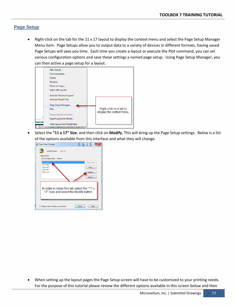
TOOLBOX 7 TRAINING TUTORIAL
Microvellum, Inc. | Submittal Drawings 77
Page Setup
Right-click on the tab for the 11 x 17 layout to display the context menu and select the Page Setup Manager
Menu item. Page Setups allow you to output data to a variety of devices in different formats, having saved
Page Setups will save you time. Each time you create a layout or execute the Plot command, you can set
various configuration options and save these settings a named page setup. Using Page Setup Manager, you
can then active a page setup for a layout.
Select the “11 x 17” Size, and then click on Modify. This will bring up the Page Setup settings. Below is a list
of the options available from this interface and what they will change.
When setting up the layout pages the Page Setup screen will have to be customized to your printing needs.
For the purpose of this tutorial please review the different options available in this screen below and then
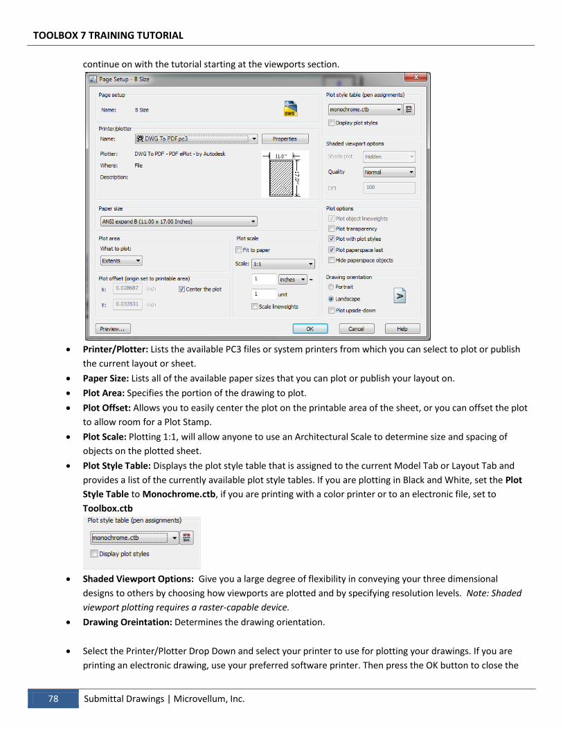
TOOLBOX 7 TRAINING TUTORIAL
78 Submittal Drawings | Microvellum, Inc.
continue on with the tutorial starting at the viewports section.
Printer/Plotter: Lists the available PC3 files or system printers from which you can select to plot or publish
the current layout or sheet.
Paper Size: Lists all of the available paper sizes that you can plot or publish your layout on.
Plot Area: Specifies the portion of the drawing to plot.
Plot Offset: Allows you to easily center the plot on the printable area of the sheet, or you can offset the plot
to allow room for a Plot Stamp.
Plot Scale: Plotting 1:1, will allow anyone to use an Architectural Scale to determine size and spacing of
objects on the plotted sheet.
Plot Style Table: Displays the plot style table that is assigned to the current Model Tab or Layout Tab and
provides a list of the currently available plot style tables. If you are plotting in Black and White, set the Plot
Style Table to Monochrome.ctb, if you are printing with a color printer or to an electronic file, set to
Toolbox.ctb
Shaded Viewport Options: Give you a large degree of flexibility in conveying your three dimensional
designs to others by choosing how viewports are plotted and by specifying resolution levels. Note: Shaded
viewport plotting requires a raster-capable device.
Drawing Oreintation: Determines the drawing orientation.
Select the Printer/Plotter Drop Down and select your printer to use for plotting your drawings. If you are
printing an electronic drawing, use your preferred software printer. Then press the OK button to close the
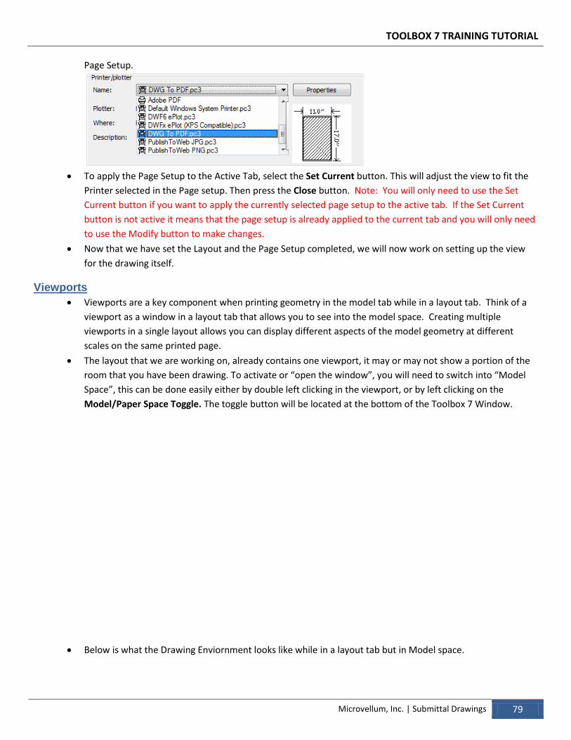
TOOLBOX 7 TRAINING TUTORIAL
Microvellum, Inc. | Submittal Drawings 79
Page Setup.
To apply the Page Setup to the Active Tab, select the Set Current button. This will adjust the view to fit the
Printer selected in the Page setup. Then press the Close button. Note: You will only need to use the Set
Current button if you want to apply the currently selected page setup to the active tab. If the Set Current
button is not active it means that the page setup is already applied to the current tab and you will only need
to use the Modify button to make changes.
Now that we have set the Layout and the Page Setup completed, we will now work on setting up the view
for the drawing itself.
Viewports
Viewports are a key component when printing geometry in the model tab while in a layout tab. Think of a
viewport as a window in a layout tab that allows you to see into the model space. Creating multiple
viewports in a single layout allows you can display different aspects of the model geometry at different
scales on the same printed page.
The layout that we are working on, already contains one viewport, it may or may not show a portion of the
room that you have been drawing. To activate or “open the window”, you will need to switch into “Model
Space”, this can be done easily either by double left clicking in the viewport, or by left clicking on the
Model/Paper Space Toggle. The toggle button will be located at the bottom of the Toolbox 7 Window.
Below is what the Drawing Enviornment looks like while in a layout tab but in Model space.
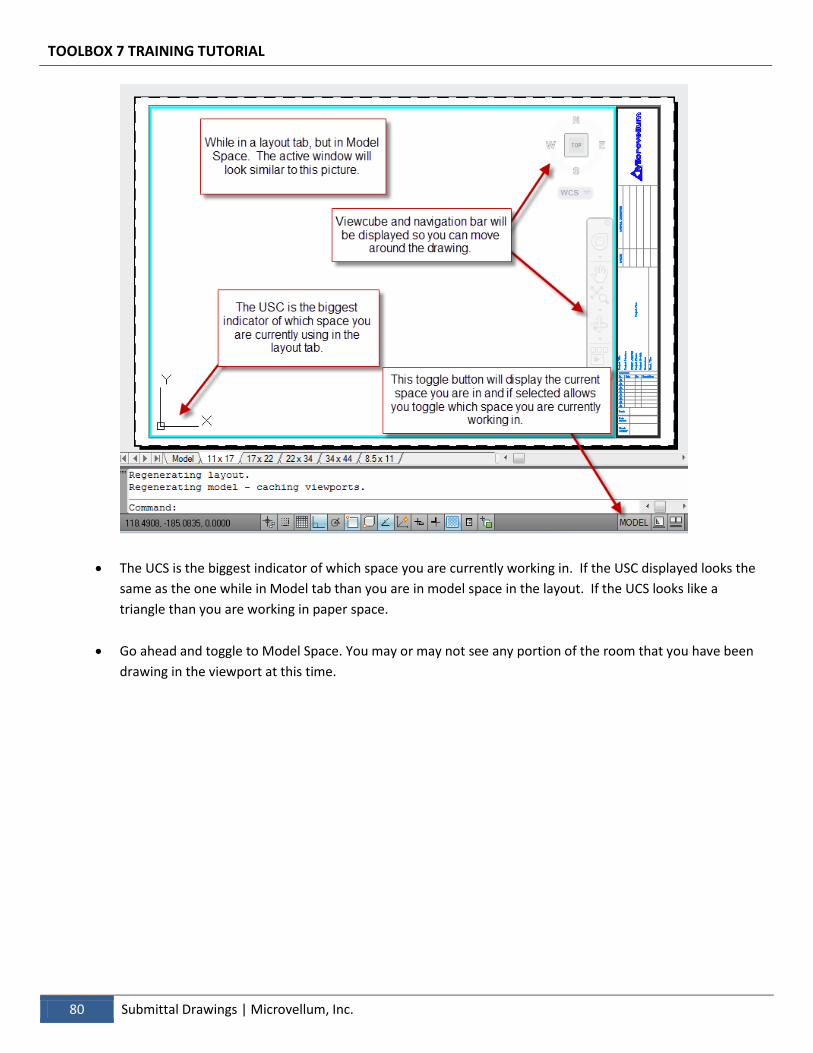
TOOLBOX 7 TRAINING TUTORIAL
80 Submittal Drawings | Microvellum, Inc.
The UCS is the biggest indicator of which space you are currently working in. If the USC displayed looks the
same as the one while in Model tab than you are in model space in the layout. If the UCS looks like a
triangle than you are working in paper space.
Go ahead and toggle to Model Space. You may or may not see any portion of the room that you have been
drawing in the viewport at this time.
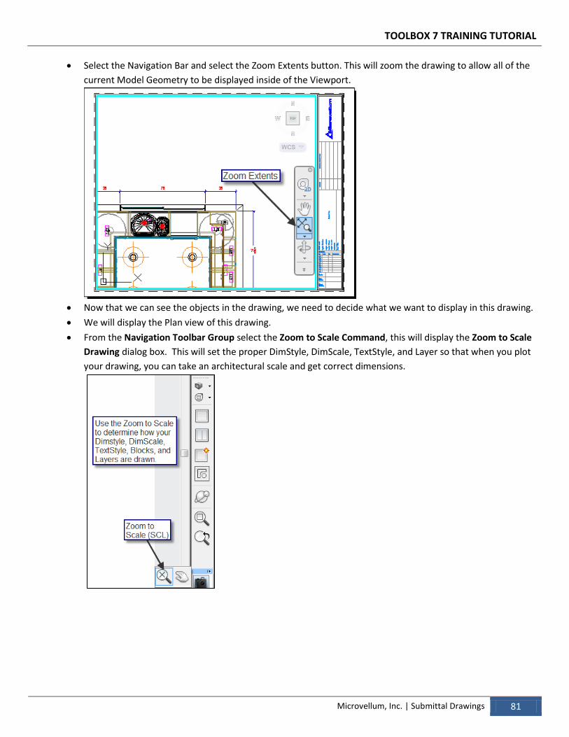
TOOLBOX 7 TRAINING TUTORIAL
Microvellum, Inc. | Submittal Drawings 81
Select the Navigation Bar and select the Zoom Extents button. This will zoom the drawing to allow all of the
current Model Geometry to be displayed inside of the Viewport.
Now that we can see the objects in the drawing, we need to decide what we want to display in this drawing.
We will display the Plan view of this drawing.
From the Navigation Toolbar Group select the Zoom to Scale Command, this will display the Zoom to Scale
Drawing dialog box. This will set the proper DimStyle, DimScale, TextStyle, and Layer so that when you plot
your drawing, you can take an architectural scale and get correct dimensions.
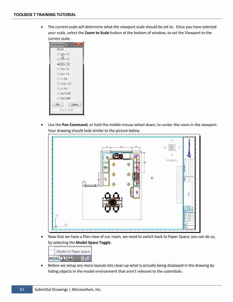
TOOLBOX 7 TRAINING TUTORIAL
82 Submittal Drawings | Microvellum, Inc.
The current scale will determine what the viewport scale should be set to. Once you have selected
your scale, select the Zoom to Scale button at the bottom of window, to set the Viewport to the
correct scale.
Use the Pan Command, or hold the middle mouse wheel down, to center the room in the viewport.
Your drawing should look similar to the picture below.
Now that we have a Plan view of our room, we need to switch back to Paper Space; you can do so,
by selecting the Model Space Toggle.
Before we setup any more layouts lets clean up what is actually being displayed in the drawing by
hiding objects in the model environment that aren’t relevant to the submittals.
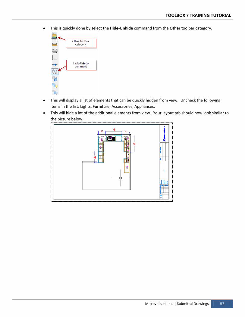
TOOLBOX 7 TRAINING TUTORIAL
Microvellum, Inc. | Submittal Drawings 83
This is quickly done by select the Hide-Unhide command from the Other toolbar category.
This will display a list of elements that can be quickly hidden from view. Uncheck the following
items in the list: Lights, Furniture, Accessories, Appliances.
This will hide a lot of the additional elements from view. Your layout tab should now look similar to
the picture below.
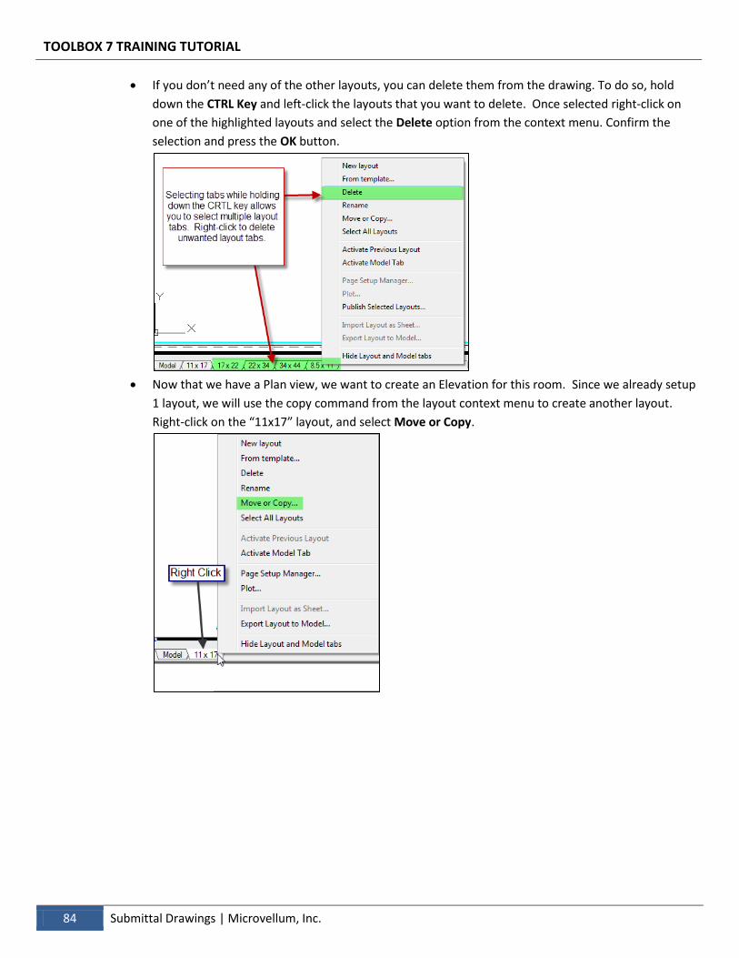
TOOLBOX 7 TRAINING TUTORIAL
84 Submittal Drawings | Microvellum, Inc.
If you don’t need any of the other layouts, you can delete them from the drawing. To do so, hold
down the CTRL Key and left-click the layouts that you want to delete. Once selected right-click on
one of the highlighted layouts and select the Delete option from the context menu. Confirm the
selection and press the OK button.
Now that we have a Plan view, we want to create an Elevation for this room. Since we already setup
1 layout, we will use the copy command from the layout context menu to create another layout.
Right-click on the “11x17” layout, and select Move or Copy.

TOOLBOX 7 TRAINING TUTORIAL
Microvellum, Inc. | Submittal Drawings 85
When the Move or Copy dialog box appears, check the box Create a copy checkbox, select (move
to end) then select the OK button.
You should now have an additional layout, it will be named 11x17 (2). At this point we should
rename the Layouts, so that it will not get confusing. Right-click on the tab you want to rename and
select Rename menu item, and change the name to Kitchen Plan View. Select the 11x17 (2) layout
and rename it to Kitchen Elevation.
Now that we have the second layout, we will setup multiple viewports in this layout so we can see
multiple 2D elevations.
Toggle to Paper Space. Select and delete the Viewport entity; it is displayed in paper space as a
turquoise box.
With no viewports in paper space we won’t be able to see any objects in the model space.
Select the Setup Viewport toolbar button from the Views toolbar category.
This will display the viewports window and allow us to add new viewport to the layout in
paperspace. From this window there are predefined viewports that you can select from.
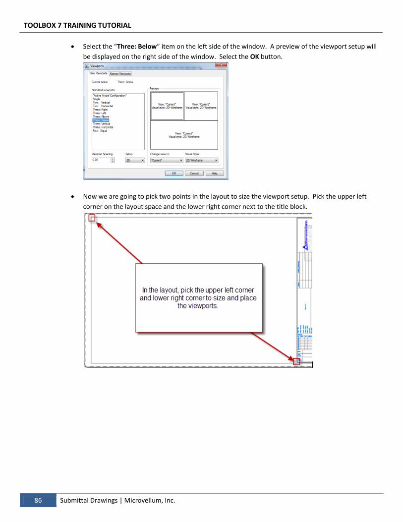
TOOLBOX 7 TRAINING TUTORIAL
86 Submittal Drawings | Microvellum, Inc.
Select the “Three: Below” item on the left side of the window. A preview of the viewport setup will
be displayed on the right side of the window. Select the OK button.
Now we are going to pick two points in the layout to size the viewport setup. Pick the upper left
corner on the layout space and the lower right corner next to the title block.
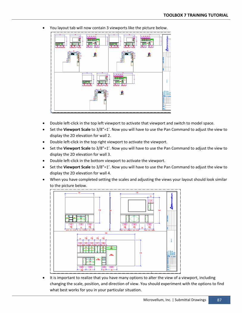
TOOLBOX 7 TRAINING TUTORIAL
Microvellum, Inc. | Submittal Drawings 87
You layout tab will now contain 3 viewports like the picture below.
Double left-click in the top left viewport to activate that viewport and switch to model space.
Set the Viewport Scale to 3/8”=1’. Now you will have to use the Pan Command to adjust the view to
display the 2D elevation for wall 2.
Double left-click in the top right viewport to activate the viewport.
Set the Viewport Scale to 3/8”=1’. Now you will have to use the Pan Command to adjust the view to
display the 2D elevation for wall 3.
Double left-click in the bottom viewport to activate the viewport.
Set the Viewport Scale to 3/8”=1’. Now you will have to use the Pan Command to adjust the view to
display the 2D elevation for wall 4.
When you have completed setting the scales and adjusting the views your layout should look similar
to the picture below.
It is important to realize that you have many options to alter the view of a viewport, including
changing the scale, position, and direction of view. You should experiment with the options to find
what best works for you in your particular situation.
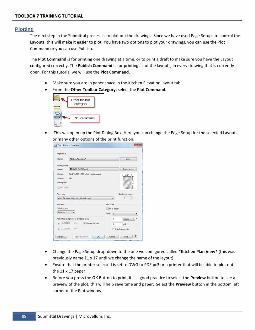
TOOLBOX 7 TRAINING TUTORIAL
88 Submittal Drawings | Microvellum, Inc.
Plotting
The next step in the Submittal process is to plot out the drawings. Since we have used Page Setups to control the
Layouts, this will make it easier to plot. You have two options to plot your drawings, you can use the Plot
Command or you can use Publish.
The Plot Command is for printing one drawing at a time, or to print a draft to make sure you have the Layout
configured correctly. The Publish Command is for printing all of the layouts, in every drawing that is currently
open. For this tutorial we will use the Plot Command.
Make sure you are in paper space in the Kitchen Elevation layout tab.
From the Other Toolbar Category, select the Plot Command.
This will open up the Plot Dialog Box. Here you can change the Page Setup for the selected Layout,
or many other options of the print function.
Change the Page Setup drop-down to the one we configured called *Kitchen Plan View* (this was
previously name 11 x 17 until we change the name of the layout).
Ensure that the printer selected is set to DWG to PDF.pc3 or a printer that will be able to plot out
the 11 x 17 paper.
Before you press the OK Button to print, it is a good practice to select the Preview button to see a
preview of the plot; this will help save time and paper. Select the Preview button in the bottom left
corner of the Plot window.

TOOLBOX 7 TRAINING TUTORIAL
Microvellum, Inc. | Submittal Drawings 89
If the Preview is acceptable, you can print from the Quick Access Toolbar at the top of the Plot
Preview Window. You also have the ability to Pan, Zoom or close the Preview to return to the Plot
Dialog Box.
Selecting the print button will plot the layout. If you are plotting to a PDF you will be asked where
you would like to save the PDF file to on your computer.
Review
You should now a basic understanding on Paper Space/Model Space works, how to add and manipulate Layouts, how to
apply Page Setups to those Layouts, how to add Viewports, and change the viewport views, add Annotations and Plot
your Layouts. It is important to realize that you have many options when it comes to submitting your drawings. Keep
your drawings simple and easy to produce at the beginning until you get a good feel for the steps, after that you can
design and plot very intricate and detailed drawings for your projects. The goal of your submittal is to convey the
construction and look of the Architects or Owners Intent for their project.
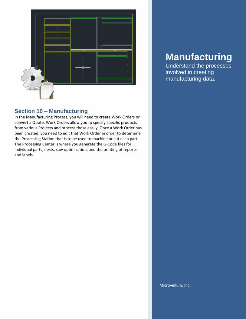
Section 10 – Manufacturing In the Manufacturing Process, you will need to create Work Orders or convert a Quote. Work Orders allow you to specify specific products from various Projects and process those easily. Once a Work Order has been created, you need to edit that Work Order in order to determine the Processing Station that is to be used to machine or cut each part. The Processing Center is where you generate the G-Code files for individual parts, nests, saw optimization, and the printing of reports and labels.
Manufacturing Understand the processes involved in creating manufacturing data.
Microvellum, Inc.
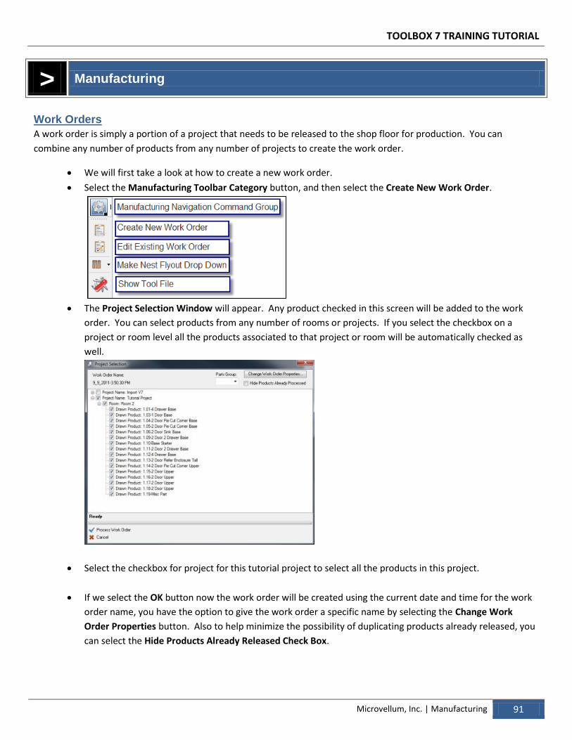
TOOLBOX 7 TRAINING TUTORIAL
Microvellum, Inc. | Manufacturing 91
> Manufacturing
Work Orders
A work order is simply a portion of a project that needs to be released to the shop floor for production. You can
combine any number of products from any number of projects to create the work order.
We will first take a look at how to create a new work order.
Select the Manufacturing Toolbar Category button, and then select the Create New Work Order.
The Project Selection Window will appear. Any product checked in this screen will be added to the work
order. You can select products from any number of rooms or projects. If you select the checkbox on a
project or room level all the products associated to that project or room will be automatically checked as
well.
Select the checkbox for project for this tutorial project to select all the products in this project.
If we select the OK button now the work order will be created using the current date and time for the work
order name, you have the option to give the work order a specific name by selecting the Change Work
Order Properties button. Also to help minimize the possibility of duplicating products already released, you
can select the Hide Products Already Released Check Box.
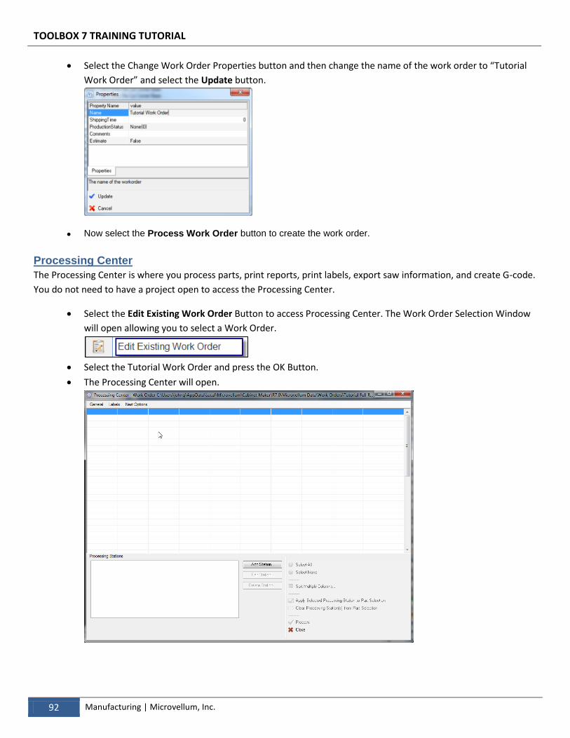
TOOLBOX 7 TRAINING TUTORIAL
92 Manufacturing | Microvellum, Inc.
Select the Change Work Order Properties button and then change the name of the work order to “Tutorial
Work Order” and select the Update button.
Now select the Process Work Order button to create the work order.
Processing Center
The Processing Center is where you process parts, print reports, print labels, export saw information, and create G-code.
You do not need to have a project open to access the Processing Center.
Select the Edit Existing Work Order Button to access Processing Center. The Work Order Selection Window
will open allowing you to select a Work Order.
Select the Tutorial Work Order and press the OK Button.
The Processing Center will open.
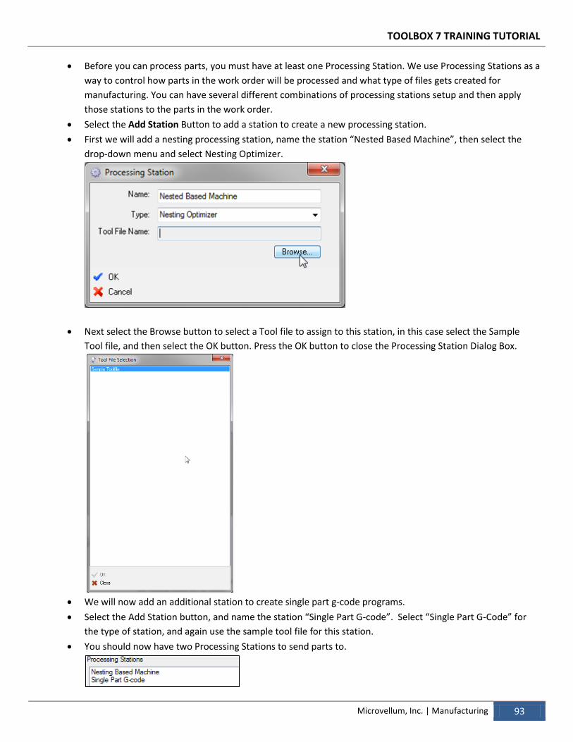
TOOLBOX 7 TRAINING TUTORIAL
Microvellum, Inc. | Manufacturing 93
Before you can process parts, you must have at least one Processing Station. We use Processing Stations as a
way to control how parts in the work order will be processed and what type of files gets created for
manufacturing. You can have several different combinations of processing stations setup and then apply
those stations to the parts in the work order.
Select the Add Station Button to add a station to create a new processing station.
First we will add a nesting processing station, name the station “Nested Based Machine”, then select the
drop-down menu and select Nesting Optimizer.
Next select the Browse button to select a Tool file to assign to this station, in this case select the Sample
Tool file, and then select the OK button. Press the OK button to close the Processing Station Dialog Box.
We will now add an additional station to create single part g-code programs.
Select the Add Station button, and name the station “Single Part G-code”. Select “Single Part G-Code” for
the type of station, and again use the sample tool file for this station.
You should now have two Processing Stations to send parts to.
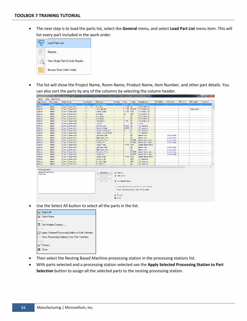
TOOLBOX 7 TRAINING TUTORIAL
94 Manufacturing | Microvellum, Inc.
The next step is to load the parts list, select the General menu, and select Load Part List menu item. This will
list every part included in the work order.
The list will show the Project Name, Room Name, Product Name, Item Number, and other part details. You
can also sort the parts by any of the columns by selecting the column header.
Use the Select All button to select all the parts in the list.
Then select the Nesting Based Machine processing station in the processing stations list.
With parts selected and a processing station selected use the Apply Selected Processing Station to Part
Selection button to assign all the selected parts to the nesting processing station.
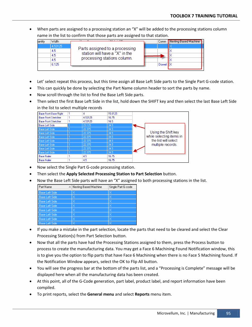
TOOLBOX 7 TRAINING TUTORIAL
Microvellum, Inc. | Manufacturing 95
When parts are assigned to a processing station an “X” will be added to the processing stations column
name in the list to confirm that those parts are assigned to that station.
Let’ select repeat this process, but this time assign all Base Left Side parts to the Single Part G-code station.
This can quickly be done by selecting the Part Name column header to sort the parts by name.
Now scroll through the list to find the Base Left Side parts.
Then select the first Base Left Side in the list, hold down the SHIFT key and then select the last Base Left Side
in the list to select multiple records
Now select the Single Part G-code processing station.
Then select the Apply Selected Processing Station to Part Selection button.
Now the Base Left Side parts will have an “X” assigned to both processing stations in the list.
If you make a mistake in the part selection, locate the parts that need to be cleared and select the Clear
Processing Station(s) from Part Selection button.
Now that all the parts have had the Processing Stations assigned to them, press the Process button to
process to create the manufacturing data. You may get a Face 6 Machining Found Notification window, this
is to give you the option to flip parts that have Face 6 Machining when there is no Face 5 Machining found. If
the Notification Window appears, select the OK to Flip All button.
You will see the progress bar at the bottom of the parts list, and a “Processing is Complete” message will be
displayed here when all the manufacturing data has been created.
At this point, all of the G-Code generation, part label, product label, and report information have been
compiled.
To print reports, select the General menu and select Reports menu item.
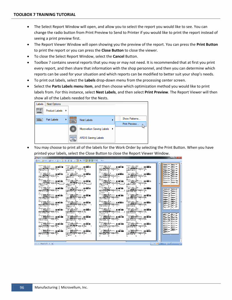
TOOLBOX 7 TRAINING TUTORIAL
96 Manufacturing | Microvellum, Inc.
The Select Report Window will open, and allow you to select the report you would like to see. You can
change the radio button from Print Preview to Send to Printer if you would like to print the report instead of
seeing a print preview first.
The Report Viewer Window will open showing you the preview of the report. You can press the Print Button
to print the report or you can press the Close Button to close the viewer.
To close the Select Report Window, select the Cancel Button.
Toolbox 7 contains several reports that you may or may not need. It is recommended that at first you print
every report, and then share that information with the shop personnel, and then you can determine which
reports can be used for your situation and which reports can be modified to better suit your shop’s needs.
To print out labels, select the Labels drop-down menu from the processing center screen.
Select the Parts Labels menu item, and then choose which optimization method you would like to print
labels from. For this instance, select Nest Labels, and then select Print Preview. The Report Viewer will then
show all of the Labels needed for the Nests.
You may choose to print all of the labels for the Work Order by selecting the Print Button. When you have
printed your labels, select the Close Button to close the Report Viewer Window.
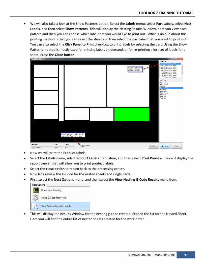
TOOLBOX 7 TRAINING TUTORIAL
Microvellum, Inc. | Manufacturing 97
We will also take a look at the Show Patterns option. Select the Labels menu, select Part Labels, select Nest
Labels, and then select Show Patterns. This will display the Nesting Results Window, here you view each
pattern and then you can choose which label that you would like to print out. What is unique about this
printing method is that you can select the sheet and then select the part label that you want to print out.
You can also select the Click Panel to Print checkbox to print labels by selecting the part. Using the Show
Patterns method is mostly used for printing labels on demand, or for re-printing a lost set of labels for a
sheet. Press the Close button.
Now we will print the Product Labels.
Select the Labels menu, select Product Labels menu item, and then select Print Preview. This will display the
report viewer that will allow you to print product labels.
Select the close option to return back to the processing center.
Now let’s review the G-Code for the nested sheets and single parts.
First, select the Nest Options menu, and then select the View Nesting G-Code Results menu item.
This will display the Results Window for the nesting g-code created. Expand the list for the Nested Sheet.
Here you will find the entire list of nested sheets created for the work order.
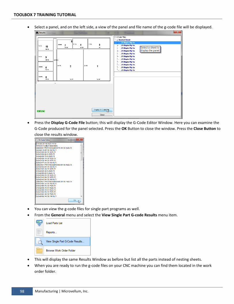
TOOLBOX 7 TRAINING TUTORIAL
98 Manufacturing | Microvellum, Inc.
Select a panel, and on the left side, a view of the panel and file name of the g-code file will be displayed.
Press the Display G-Code File button; this will display the G-Code Editor Window. Here you can examine the
G-Code produced for the panel selected. Press the OK Button to close the window. Press the Close Button to
close the results window.
You can view the g-code files for single part programs as well.
From the General menu and select the View Single Part G-code Results menu item.
This will display the same Results Window as before but list all the parts instead of nesting sheets.
When you are ready to run the g-code files on your CNC machine you can find them located in the work
order folder.
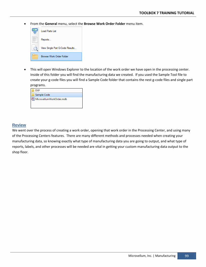
TOOLBOX 7 TRAINING TUTORIAL
Microvellum, Inc. | Manufacturing 99
From the General menu, select the Browse Work Order Folder menu item.
This will open Windows Explorer to the location of the work order we have open in the processing center.
Inside of this folder you will find the manufacturing data we created. If you used the Sample Tool file to
create your g-code files you will find a Sample Code folder that contains the nest g-code files and single part
programs.
Review
We went over the process of creating a work order, opening that work order in the Processing Center, and using many
of the Processing Centers features. There are many different methods and processes needed when creating your
manufacturing data, so knowing exactly what type of manufacturing data you are going to output, and what type of
reports, labels, and other processes will be needed are vital in getting your custom manufacturing data output to the
shop floor.