too much vibration
TRANSCRIPT

REPRINT
PRÜFTECHNIK Condition Monitoring GmbH • 85737 Ismaning • eMail: [email protected] • www.pruftechnik.comA member of the PRÜFTECHNIK Group
Dr. Edwin Becker,PRÜFTECHNIK Condition Monitoring
Michael Stachelhaus,PRÜFTECHNIK Alignment Systems
Too much vibration?
2
Air columnvibration
Fan pumps
Rotatingstall
Asymmetricparalleloperation
Blade passfrequency
Installationresonance
Belt flaw
Beltvibration
Componentvibration/resonance
Imbalance /shaft runout
Misalignment
Couplingwear
Couplingclamps
Seal slip
Shaft rub
All rollerbearingdamage
Aeromechanical excitations Machine vibrations Frictional vibrations
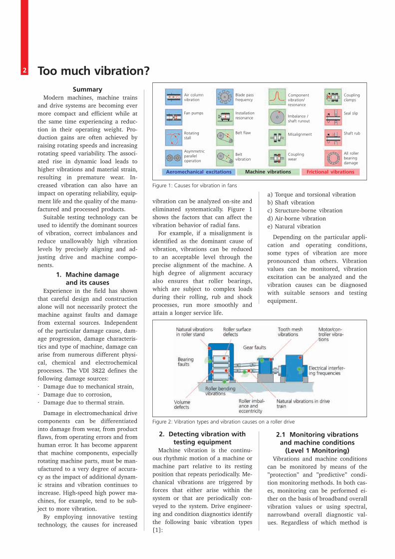
Figure 1: Causes for vibration in fans
Too much vibration?Summary
Modern machines, machine trainsand drive systems are becoming evermore compact and efficient while atthe same time experiencing a reduc-tion in their operating weight. Pro-duction gains are often achieved byraising rotating speeds and increasingrotating speed variability. The associ-ated rise in dynamic load leads tohigher vibrations and material strain,resulting in premature wear. In-creased vibration can also have animpact on operating reliability, equip-ment life and the quality of the manu-factured and processed products.
Suitable testing technology can beused to identify the dominant sourcesof vibration, correct imbalances andreduce unallowably high vibrationlevels by precisely aligning and ad-justing drive and machine compo-nents.
1. Machine damageand its causes
Experience in the field has shownthat careful design and constructionalone will not necessarily protect themachine against faults and damagefrom external sources. Independentof the particular damage cause, dam-age progression, damage characteris-tics and type of machine, damage canarise from numerous different physi-cal, chemical and electrochemicalprocesses. The VDI 3822 defines thefollowing damage sources:· Damage due to mechanical strain,· Damage due to corrosion,· Damage due to thermal strain.
Damage in electromechanical drivecomponents can be differentiatedinto damage from wear, from productflaws, from operating errors and fromhuman error. It has become apparentthat machine components, especiallyrotating machine parts, must be man-ufactured to a very degree of accura-cy as the impact of additional dynam-ic strains and vibration continues toincrease. High-speed high power ma-chines, for example, tend to be sub-ject to more vibration.
By employing innovative testingtechnology, the causes for increased
vibration can be analyzed on-site andeliminated systematically. Figure 1shows the factors that can affect thevibration behavior of radial fans.
For example, if a misalignment isidentified as the dominant cause ofvibration, vibrations can be reducedto an acceptable level through theprecise alignment of the machine. Ahigh degree of alignment accuracyalso ensures that roller bearings,which are subject to complex loadsduring their rolling, rub and shockprocesses, run more smoothly andattain a longer service life.
2. Detecting vibration withtesting equipment
Machine vibration is the continu-ous rhythmic motion of a machine ormachine part relative to its restingposition that repeats periodically. Me-chanical vibrations are triggered byforces that either arise within thesystem or that are periodically con-veyed to the system. Drive engineer-ing and condition diagnostics identifythe following basic vibration types[1]:
a) Torque and torsional vibrationb) Shaft vibrationc) Structure-borne vibrationd) Air-borne vibratione) Natural vibration
Depending on the particular appli-cation and operating conditions,some types of vibration are morepronounced than others. Vibrationvalues can be monitored, vibrationexcitation can be analyzed and thevibration causes can be diagnosedwith suitable sensors and testingequipment.
2.1 Monitoring vibrationsand machine conditions
(Level 1 Monitoring)Vibrations and machine conditions
can be monitored by means of the”protection” and ”predictive” condi-tion monitoring methods. In both cas-es, monitoring can be performed ei-ther on the basis of broadband overallvibration values or using spectral,narrowband overall diagnostic val-ues. Regardless of which method is
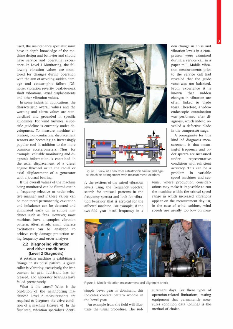
Figure 2: Vibration types and vibration causes on a roller drive
3used, the maintenance specialist musthave in-depth knowledge of the ma-chine design and behavior and shouldhave service and operating experi-ence. In Level 1 Monitoring, the fol-lowing vibration values are moni-tored for changes during operationwith the aim of avoiding sudden dam-age and catastrophic failure [2]:noise, vibration severity, peak-to-peakshaft vibrations, axial displacementsand other vibration values.
In some industrial applications, thecharacteristic overall values and thewarning and alarm values are stan-dardized and grounded in specificguidelines. For wind turbines, a spe-cific guideline is currently under de-velopment. To measure machine vi-bration, non-contacting displacementsensors are becoming an increasinglypopular tool in addition to the morecommon accelerometers. Thus, forexample, valuable monitoring and di-agnosis information is contained inthe axial displacement of a dieselengine flywheel or in the radial oraxial displacement of a generatorwith a journal bearing.
If the overall values of the machinebeing monitored can be filtered out ina frequency-selective or order-selec-tive manner, and if these values canbe monitored permanently, cavitationand imbalance can be detected andeliminated early on in simple ma-chines such as fans. However, mostmachines have a complex vibrationpattern. Alternatively, small discreteexcitations can be analyzed toachieve early damage protection us-ing frequency and order analyses.
2.2 Diagnosing vibrationand drive conditions(Level 2 Diagnosis)
A rotating machine is exhibiting achange in its noise pattern, a guideroller is vibrating excessively, the ironcontent in gear lubricant has in-creased, and generator bearings havefailed prematurely.
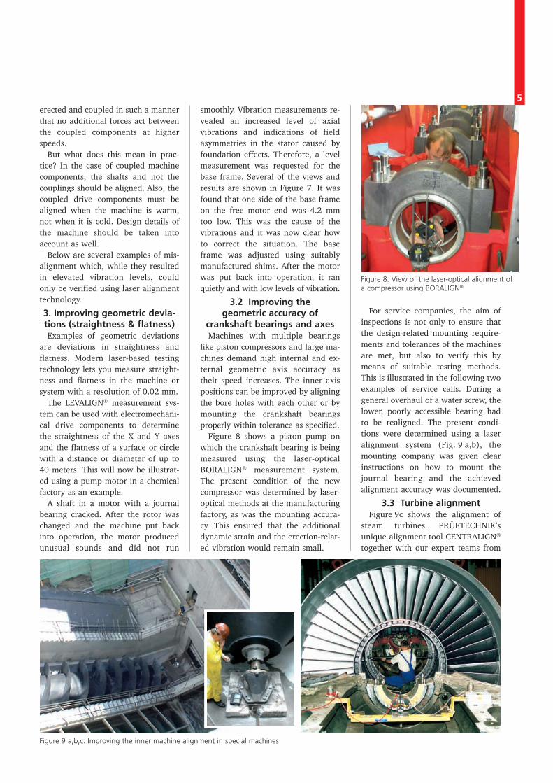
What is the cause? What is thecondition of the neighboring ma-chines? Level 2 measurements arerequired to diagnose the drive condi-tion of a machine (Figure 4). In thefirst step, vibration specialists identi-
fy the exciters of the raised vibrationlevels using the frequency spectra,search for unusual patterns in thefrequency spectra and look for vibra-tion behavior that is atypical for theaffected machine. For example, if thetwo-fold gear mesh frequency in a
simple bevel gear is dominant, thisindicates contact pattern wobble inthe bevel gear.
An example from the field will illus-trate the usual procedure. The sud-
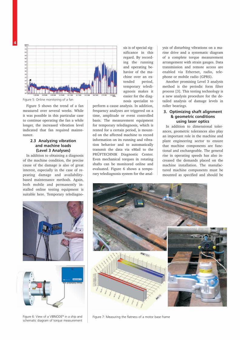
den change in noise andvibration levels in a com-pressor were examinedduring a service call in apaper mill. Mobile vibra-tion measurements priorto the service call hadrevealed that the guidevane was not balanced.From experience it isknown that suddenchanges in vibration areoften linked to bladetears. Therefore, a video-endoscopic examinationwas performed after di-agnosis, which indeed re-vealed a defective bladein the compressor stage.
A prerequisite for thiskind of diagnosis mea-surement is that mean-ingful frequency and or-der spectra are measuredunder representativeconditions with sufficientaccuracy. This can be aproblem in variablespeed machines and sys-
tems, where production consider-ations may make it impossible to runthe machine within the critical speedrange in which increased vibrationsappear on the measurement day. Or,in the case of wind turbines, windspeeds are usually too low on mea-
surement days. For these types ofoperation-related limitations, testingequipment that permanently mea-sures condition data (online) is themethod of choice.
Figure 3: View of a fan after catastrophic failure and typi-cal machine arrangement with measurement locations.
Figure 4: Mobile vibration measurement and alignment check
4
Figure 5 shows the trend of a fanmeasured over several weeks. Whileit was possible in this particular caseto continue operating the fan a whilelonger, the increased vibration levelindicated that fan required mainte-nance.
2.3 Analyzing vibrationand machine loads(Level 3 Analyses)
In addition to obtaining a diagnosisof the machine condition, the precisecause of the damage is also of greatinterest, especially in the case of re-peating damage and availability-based maintenance methods. Again,both mobile and permanently in-stalled online testing equipment issuitable here. Temporary telediagno-
sis is of special sig-nificance in thisregard. By record-ing the runningand operating be-havior of the ma-chine over an ex-tended period,temporary teledi-agnosis makes iteasier for the diag-nosis specialist to
perform a cause analysis. In addition,frequency analyses are triggered on atime, amplitude or event controlledbasis. The measurement equipmentfor temporary telediagnosis, which isrented for a certain period, is mount-ed on the affected machine to recordinformation on its running and vibra-tion behavior and to automaticallytransmit the data via eMail to thePRÜFTECHNIK Diagnostic Center.Even mechanical torques in rotatingshafts can be monitored online andevaluated. Figure 6 shows a tempo-rary telediagnosis system for the anal-
ysis of disturbing vibrations on a ma-rine drive and a systematic diagramof a complete torque measurementarrangement with strain gauges. Datatransmission and remote access areenabled via Ethernet, radio, tele-phone or mobile radio (GPRS).
Another promising Level 3 analysismethod is the periodic form filterprocess [3]. This testing technology isa new analysis procedure for the de-tailed analysis of damage levels inroller bearings.
3. Optimizing shaft alignment& geometric conditions
using laser opticsIn addition to dimensional toler-
ances, geometric tolerances also playan important role in the machine andplant engineering sector to ensurethat machine components are func-tional and exchangeable. The generalrise in operating speeds has also in-creased the demands placed on themachine installation. The manufac-tured machine components must bemounted as specified and should be
Figure 5: Online monitoring of a fan
Figure 6: View of a VIBNODE® in a ship andschematic diagram of torque measurement
Figure 7: Measuring the flatness of a motor base frame
5erected and coupled in such a mannerthat no additional forces act betweenthe coupled components at higherspeeds.
But what does this mean in prac-tice? In the case of coupled machinecomponents, the shafts and not thecouplings should be aligned. Also, thecoupled drive components must bealigned when the machine is warm,not when it is cold. Design details ofthe machine should be taken intoaccount as well.
Below are several examples of mis-alignment which, while they resultedin elevated vibration levels, couldonly be verified using laser alignmenttechnology.
3. Improving geometric devia-tions (straightness & flatness)Examples of geometric deviations
are deviations in straightness andflatness. Modern laser-based testingtechnology lets you measure straight-ness and flatness in the machine orsystem with a resolution of 0.02 mm.
The LEVALIGN® measurement sys-tem can be used with electromechani-cal drive components to determinethe straightness of the X and Y axesand the flatness of a surface or circlewith a distance or diameter of up to40 meters. This will now be illustrat-ed using a pump motor in a chemicalfactory as an example.
A shaft in a motor with a journalbearing cracked. After the rotor waschanged and the machine put backinto operation, the motor producedunusual sounds and did not run
smoothly. Vibration measurements re-vealed an increased level of axialvibrations and indications of fieldasymmetries in the stator caused byfoundation effects. Therefore, a levelmeasurement was requested for thebase frame. Several of the views andresults are shown in Figure 7. It wasfound that one side of the base frameon the free motor end was 4.2 mmtoo low. This was the cause of thevibrations and it was now clear howto correct the situation. The baseframe was adjusted using suitablymanufactured shims. After the motorwas put back into operation, it ranquietly and with low levels of vibration.
3.2 Improving thegeometric accuracy of
crankshaft bearings and axesMachines with multiple bearings
like piston compressors and large ma-chines demand high internal and ex-ternal geometric axis accuracy astheir speed increases. The inner axispositions can be improved by aligningthe bore holes with each other or bymounting the crankshaft bearingsproperly within tolerance as specified.
Figure 8 shows a piston pump onwhich the crankshaft bearing is beingmeasured using the laser-opticalBORALIGN® measurement system.The present condition of the newcompressor was determined by laser-optical methods at the manufacturingfactory, as was the mounting accura-cy. This ensured that the additionaldynamic strain and the erection-relat-ed vibration would remain small.
For service companies, the aim ofinspections is not only to ensure thatthe design-related mounting require-ments and tolerances of the machinesare met, but also to verify this bymeans of suitable testing methods.This is illustrated in the following twoexamples of service calls. During ageneral overhaul of a water screw, thelower, poorly accessible bearing hadto be realigned. The present condi-tions were determined using a laseralignment system (Fig. 9 a,b), themounting company was given clearinstructions on how to mount thejournal bearing and the achievedalignment accuracy was documented.
3.3 Turbine alignmentFigure 9c shows the alignment of
steam turbines. PRÜFTECHNIK’sunique alignment tool CENTRALIGN®
together with our expert teams from
Figure 8: View of the laser-optical alignment ofa compressor using BORALIGN®
Figure 9 a,b,c: Improving the inner machine alignment in special machines
6
misaligned aligned
PRUFTECHNIK-WIBREM are speciali-zed in the measurement of flow pathclearances and bearing alignment ofsteam turbines, world wide. Thisincludes measurement of rotor curva-ture and vibration measurement andanalysis with root cause determinati-on. We also specialize in thermalgrowth assessment of machine setsand machine trains[4].
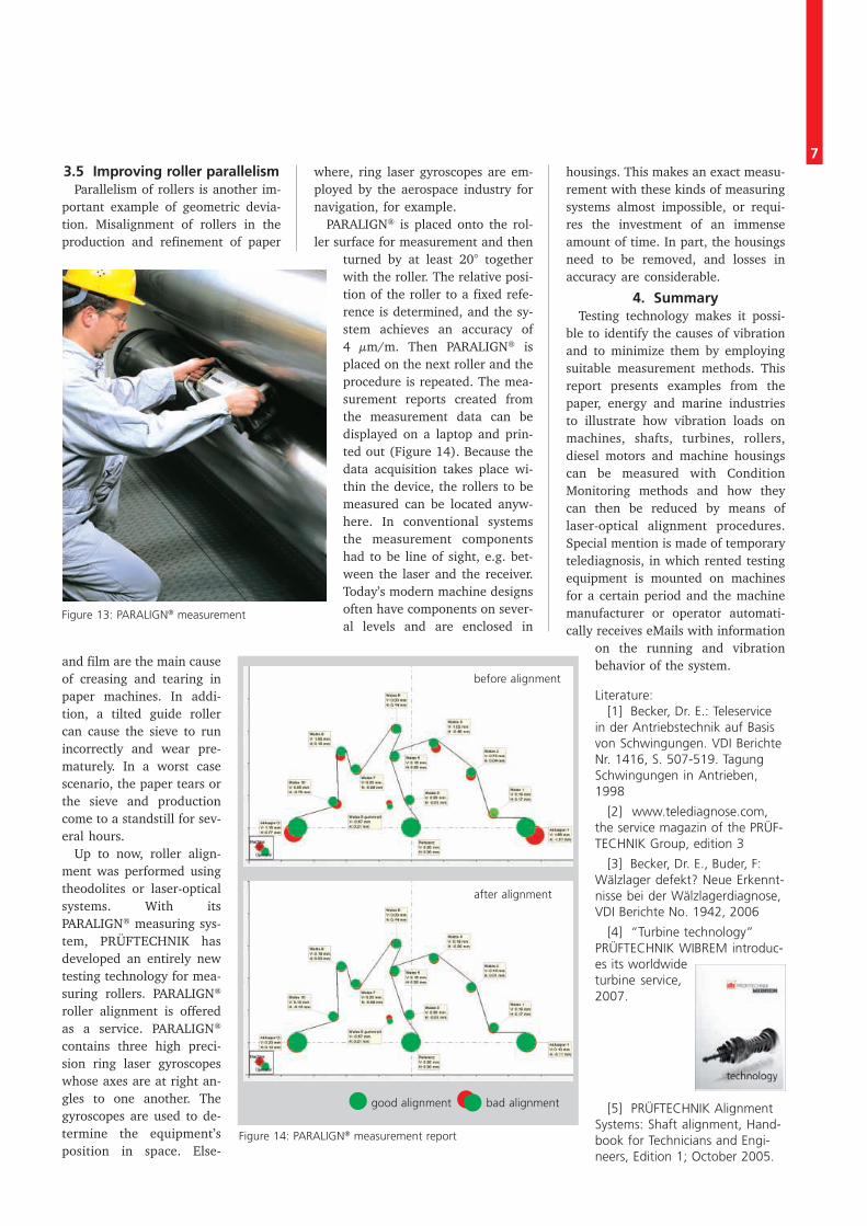
3.4 Improving alignmentAligning belt pulleysIf a machines with a belt drive
begins to vibrate or if the belt flutters,frequency analysis can be employedto identify the cause, e.g. a belt flaw,unequally loaded belts, unbalancedor eccentrically drilled disks, or amisalignment in the two axes of rota-tion of the disks. For example, in thecase of misalignment, the frequency
spectrum would be dominated by therotational vibrations and their har-monics. Using a simple laser align-ment device for belt drives, such asPULLALIGN®, the radial and angularalignment between the two belt pul-leys can be improved. Figure 10shows the measurement setup, thepossible alignment errors and the set-ting options for these types of the beltdrives. The mirrored laser beam dou-bles the resolution and correctionscan be made directly on the beltpulley itself.
Fig. 10: Belt drive & types of alignment error
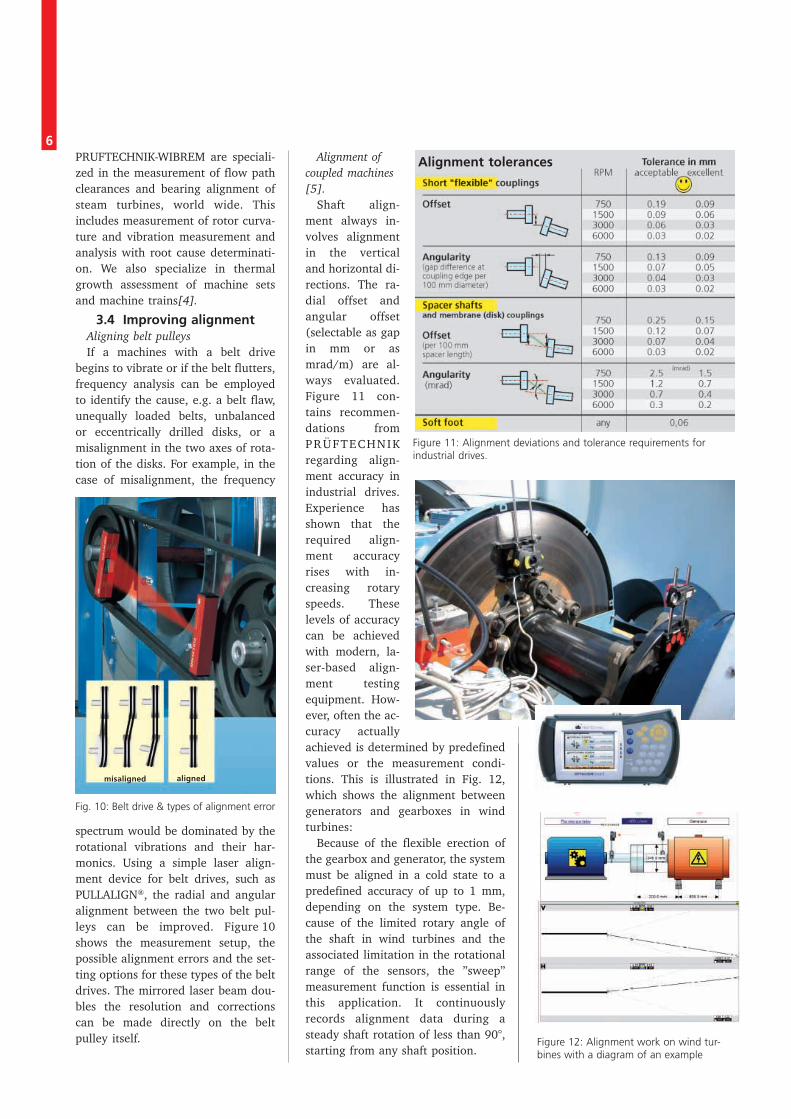
Alignment ofcoupled machines[5].
Shaft align-ment always in-volves alignmentin the verticaland horizontal di-rections. The ra-dial offset andangular offset(selectable as gapin mm or asmrad/m) are al-ways evaluated.Figure 11 con-tains recommen-dations fromPRÜFTECHNIKregarding align-ment accuracy inindustrial drives.Experience hasshown that therequired align-ment accuracyrises with in-creasing rotaryspeeds. Theselevels of accuracycan be achievedwith modern, la-ser-based align-ment testingequipment. How-ever, often the ac-curacy actuallyachieved is determined by predefinedvalues or the measurement condi-tions. This is illustrated in Fig. 12,which shows the alignment betweengenerators and gearboxes in windturbines:
Because of the flexible erection ofthe gearbox and generator, the systemmust be aligned in a cold state to apredefined accuracy of up to 1 mm,depending on the system type. Be-cause of the limited rotary angle ofthe shaft in wind turbines and theassociated limitation in the rotationalrange of the sensors, the ”sweep”measurement function is essential inthis application. It continuouslyrecords alignment data during asteady shaft rotation of less than 90°,starting from any shaft position.
Figure 11: Alignment deviations and tolerance requirements forindustrial drives.
Alignment tolerances
Figure 12: Alignment work on wind tur-bines with a diagram of an example
73.5 Improving roller parallelism
Parallelism of rollers is another im-portant example of geometric devia-tion. Misalignment of rollers in theproduction and refinement of paper
and film are the main causeof creasing and tearing inpaper machines. In addi-tion, a tilted guide rollercan cause the sieve to runincorrectly and wear pre-maturely. In a worst casescenario, the paper tears orthe sieve and productioncome to a standstill for sev-eral hours.
Up to now, roller align-ment was performed usingtheodolites or laser-opticalsystems. With itsPARALIGN® measuring sys-tem, PRÜFTECHNIK hasdeveloped an entirely newtesting technology for mea-suring rollers. PARALIGN®
roller alignment is offeredas a service. PARALIGN®
contains three high preci-sion ring laser gyroscopeswhose axes are at right an-gles to one another. Thegyroscopes are used to de-termine the equipment’sposition in space. Else-
where, ring laser gyroscopes are em-ployed by the aerospace industry fornavigation, for example.
PARALIGN® is placed onto the rol-ler surface for measurement and then
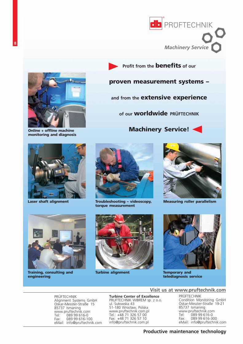
turned by at least 20° togetherwith the roller. The relative posi-tion of the roller to a fixed refe-rence is determined, and the sy-stem achieves an accuracy of4 µm/m. Then PARALIGN® isplaced on the next roller and theprocedure is repeated. The mea-surement reports created fromthe measurement data can bedisplayed on a laptop and prin-ted out (Figure 14). Because thedata acquisition takes place wi-thin the device, the rollers to bemeasured can be located anyw-here. In conventional systemsthe measurement componentshad to be line of sight, e.g. bet-ween the laser and the receiver.Today’s modern machine designsoften have components on sever-al levels and are enclosed in
Figure 13: PARALIGN® measurement
housings. This makes an exact measu-rement with these kinds of measuringsystems almost impossible, or requi-res the investment of an immenseamount of time. In part, the housingsneed to be removed, and losses inaccuracy are considerable.
4. SummaryTesting technology makes it possi-
ble to identify the causes of vibrationand to minimize them by employingsuitable measurement methods. Thisreport presents examples from thepaper, energy and marine industriesto illustrate how vibration loads onmachines, shafts, turbines, rollers,diesel motors and machine housingscan be measured with ConditionMonitoring methods and how theycan then be reduced by means oflaser-optical alignment procedures.Special mention is made of temporarytelediagnosis, in which rented testingequipment is mounted on machinesfor a certain period and the machinemanufacturer or operator automati-cally receives eMails with information
on the running and vibrationbehavior of the system.
Literature:[1] Becker, Dr. E.: Teleservice
in der Antriebstechnik auf Basisvon Schwingungen. VDI BerichteNr. 1416, S. 507-519. TagungSchwingungen in Antrieben‚1998
[2] www.telediagnose.com,the service magazin of the PRÜF-TECHNIK Group, edition 3
[3] Becker, Dr. E., Buder, F:Wälzlager defekt? Neue Erkennt-nisse bei der Wälzlagerdiagnose,VDI Berichte No. 1942, 2006
[4] “Turbine technology”PRÜFTECHNIK WIBREM introduc-es its worldwideturbine service,2007.
[5] PRÜFTECHNIK AlignmentSystems: Shaft alignment, Hand-book for Technicians and Engi-neers, Edition 1; October 2005.
good alignment bad alignment
before alignment
after alignment
Figure 14: PARALIGN® measurement report
8
Productive maintenance technology
Visit us at www.pruftechnik.comTurbine Center of ExcellencePRUFTECHNIK WIBREM sp. z o.o.ul. Sułowska 4351-180 Wrocław, Polskawww.pruftechnik.com.plTel.: +48 71 326 57 00Fax: +48 71 326 57 [email protected]
Profit from the benefits of our
proven measurement systems –
and from the extensive experience
of our worldwide PRÜFTECHNIK
Machinery Service!Online + offline machinemonitoring and diagnosis
Laser shaft alignment
Training, consulting andengineering
Troubleshooting – videoscopy,torque measurement
Turbine alignment Temporary andtelediagnosis service
Measuring roller parallelism
PRÜFTECHNIKCondition Monitoring GmbHOskar-Messter-Straße 19-2185737 Ismaningwww.pruftechnik.comTel: 089 99 616-0Fax: 089 99 616-300eMail: [email protected]
PRÜFTECHNIKAlignment Systems GmbHOskar-Messter-Straße 1585737 Ismaningwww.pruftechnik.comTel: 089 99 616-0Fax: 089 99 616-100eMail: [email protected]