tm woodworking to improve your home bathroom …wood.woodtools.nov.ru/mag/wb/wb_268.pdf ·...
TRANSCRIPT
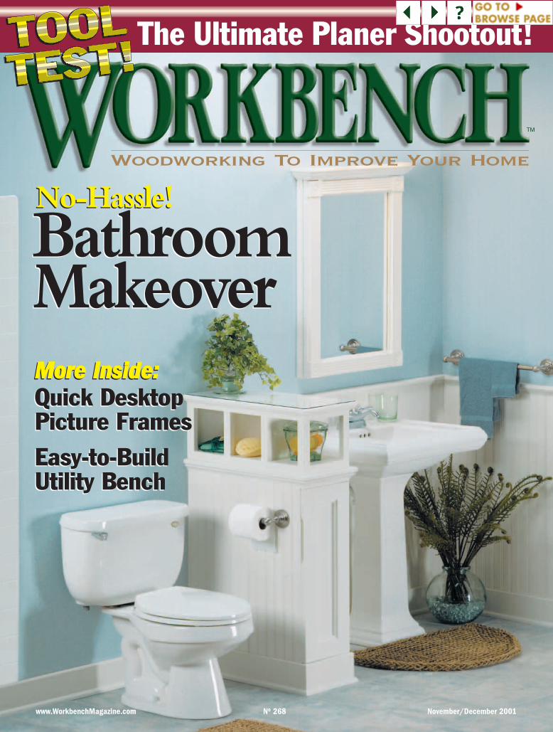
www.WorkbenchMagazine.com No 268 November/December 2001
Woodworking To Improve Your Home
TM
The Ultimate Planer Shootout!
Easy-to-BuildUtility BenchEasy-to-BuildUtility Bench
BathroomMakeoverBathroomMakeover
No-Hassle!No-Hassle!
MMoorree IInnssiiddee::Quick DesktopPicture Frames
MMoorree IInnssiiddee::Quick DesktopPicture Frames
Contents
2 W O R K B E N C H ■■ N O V E M B E R | D E C E M B E R 2 0 0 1
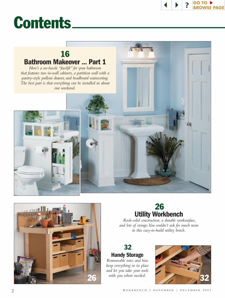
26Utility Workbench
Rock-solid construction, a durable worksurface,and lots of storage.You couldn’t ask for much more
in this easy-to-build utility bench.
32Handy Storage
Removeable totes and binskeep everything in its placeand let you take your toolswith you where needed.26 32
16Bathroom Makeover ... Part 1
Here’s a no-hassle “facelift” for your bathroomthat features two in-wall cabinets, a partition wall with apantry-style pullout drawer, and beadboard wainscoting.The best part is that everything can be installed in about
one weekend.
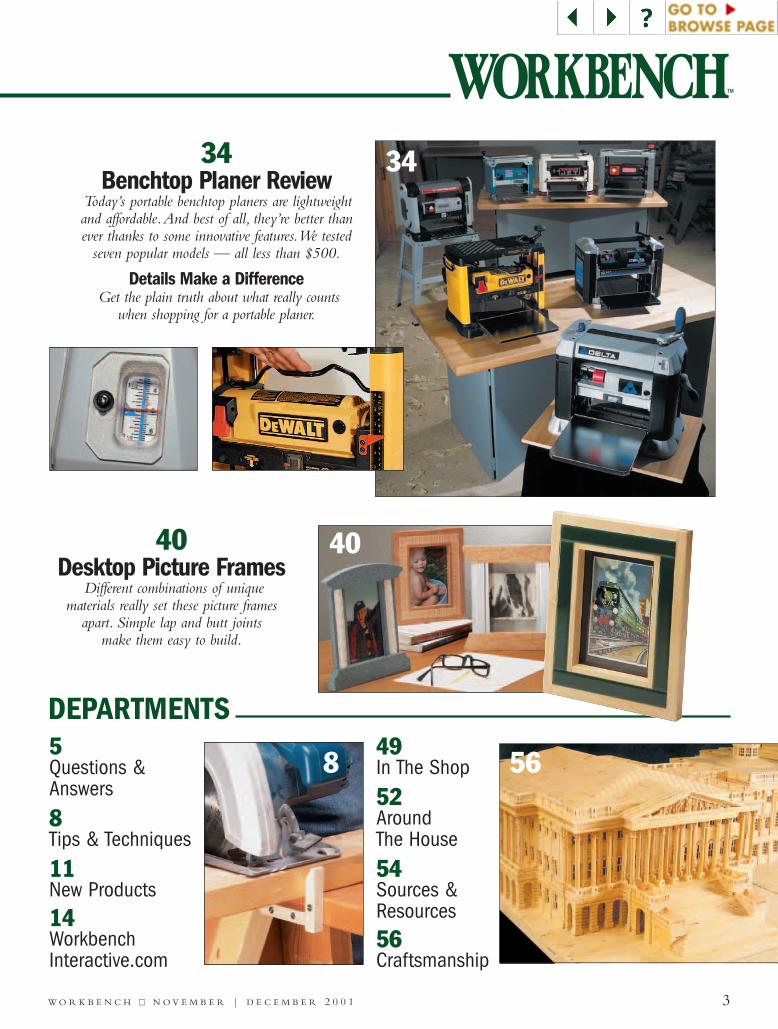
34Benchtop Planer Review
Today’s portable benchtop planers are lightweightand affordable.And best of all, they’re better thanever thanks to some innovative features.We tested
seven popular models — all less than $500.
Details Make a DifferenceGet the plain truth about what really counts
when shopping for a portable planer.
5Questions & Answers
8Tips & Techniques
11New Products14WorkbenchInteractive.com
49In The Shop
52Around The House
54Sources & Resources56Craftsmanship
3W O R K B E N C H ■■ N O V E M B E R | D E C E M B E R 2 0 0 1
TM
DEPARTMENTS
568
34
40Desktop Picture Frames
Different combinations of uniquematerials really set these picture frames
apart. Simple lap and butt joints make them easy to build.
40
Sometimes tackling a large homeimprovement project is likeknocking over a row of domi-
noes. One part of the project leads toanother, then another, and then . . .
BATHROOM MAKEOVER. Thebathroom makeover featured in thisissue is a good example. It started outas a simple idea — to replace an out-dated vanity with a pedestal sink.
The new sink looked great, and itmade the bathroom seem bigger.There was just one problem — stor-age. With the vanity removed, therewasn’t any place to put things.
Our solution was to build threestorage projects: a mirrored medicinecabinet, a partition with a pantry-style, pull-out drawer, and an in-walltowel storage rack.Then to tie thingstogether, we installed wainscoting onthe walls around the sink.
All in all, I couldn’t be more pleasedwith the results. But don’t take my
word for it.Turn to the article begin-ning on page 16 to see how these sim-ple woodworking projects completelytransformed the appearance of whatwas a very ordinary looking bathroom.
A LITTLE HELP. While you’re atit, I could use your help. Since thebathroom facelift is a fairly involvedproject, we’re featuring Part 1 only ofthe article in this issue (the partition,wainscoting, and trim). Part 2 (themedicine cabinet and towel rack) willappear in the next issue of Workbench.
To see what you think about thistwo-part approach,we’ve set up a shortsurvey at WorkbenchMagazine.comPlease visit us to answer a few ques-tions, or send a self-addressed stampedenvelope to the address below.
Editorial Questions:Workbench Magazine2200 Grand Ave.Des Moines, IA 50312email: [email protected]
Corporate Services:Corporate Vice Presidents:
Douglas L. Hicks, Mary R. Scheve, Controller: Robin Hutchinson,Senior Accountant: Laura Thomas, Accounts Payable: Mary Schultz,Accounts Receivable: Margo Petrus, Production Director: GeorgeChmielarz, Network Administrator: Cris Schwanebeck, New MediaManager: Gordon C. Gaippe, Web Site Art Director: EugenePedersen, Web Server Administrator: Carol Schoeppler, Web Site ContentManagers: David Briggs, Sue M. Moe, Professional Development Director:Michal Sigel, Human Resources Assistant: Kirsten Koele, Office Manager:Noelle M. Carroll, Receptionist: Jeanne Johnson, Mail/Delivery Clerk:Lou Webber • Circulation: Subscriber Services Director: Sandy Baum,New Business Director: Wayde Klingbeil, Multi-Media PromotionsManager: Rick Junkins, Renewal Manager: Paige Rogers, Billing &Collections Manager: Rebecca Cunningham, Circulation MarketingAnalyst: Kris Schlemmer, Associate Circulation Marketing Analyst: PaulaM. DeMatteis, Promotions Analyst: Patrick A. Walsh • CreativeResources: Associate Editor: Craig Ruegsegger, Assistant Editors: JosephE. Irwin, Joel Hess, Art Director: Douglas A. Flint, Senior GraphicDesigners: Chris Glowacki, Mark Hayes, Robin Friend, GraphicDesigner: Vu Nguyen • Products Group: Operations Director: BobBaker, Customer Service Manager: Jennie Enos, Warehouse Supervisor:Nancy Johnson, Buyer: Linda Jones, Administrative Assistant: NancyDowney, Technical Service Representative: Johnny Audette, CustomerService Team Leader: Tammy Truckenbrod, Senior Customer ServiceRepresentatives: Anna Cox, April Revell, Customer Service Representatives:Deborah Rich, Valerie Jo Riley, Eddie Arthur, Warehouse Staff: SylviaCarey, Sheryl Knox, Albert Voigt, • Woodsmith Store: Manager:Dave Larson, Assistant Manager: Tim Thelen, Sales Staff: WendellStone, Jim Barnett, Harold Cashman, Mark Johnson, Shipping andRecieving: Larry Morrison, Office Manager: Vicki Edwards
VOLUME 57 NUMBER 6EDITOR Tim Robertson
SENIOR DESIGN EDITOR Jim DowningASSOCIATE EDITORS Bill Link, Kevin Shoesmith
Erich LageASSISTANT EDITOR Mike DonovanTOOL TEST EDITOR Ellis Walentine
ART DIRECTOR Robert L. FossSR. ILLUSTRATOR/SPECIAL PROJECTS Kim Downing
SENIOR ILLUSTRATORS Susan R. JessenMark S. Graves
ILLUSTRATOR Robert McCammon
CREATIVE DIRECTOR Ted KralicekSENIOR PHOTOGRAPHER Crayola England
WEB DESIGNER Kara BlessingPROJECT DEVELOPER Ken Munkel
PROJECT DESIGNERS Chris Fitch & Craig IsekeSHOP CRAFTSMEN Steve Curtis & Steve Johnson
ELEC. PUB. DIRECTOR Douglas M. LidsterPRE-PRESS IMAGE SPECS. Troy Clark
Minniette Johnson
PRESIDENT & PUBLISHER Donald B. Peschke
GROUP DIRECTOR - MARKETING AND SALESFritz Craiger (515) 875-7300
ADVERTISING SALES MANAGERSMary K. Day (515) 875-7200
George A. Clark (515) 875-7100ADVERTISING COORDINATOR
Nicolle Carter (515) 875-7135
4 W O R K B E N C H ■■ N O V E M B E R | D E C E M B E R 2 0 0 1
EDITOR’S NOTES
TM
Subscriber Services:Workbench Customer ServiceP.O. Box 842 Des Moines, IA 50304-9961 Phone: (800) 311-3991Fax: (515) 283-0447 Online: www.WorkbenchMagazine.com
WORKBENCH (ISSN 0043-8057) is published bimonthly(Jan., Mar., May, July, Sept., Nov.) by August Home Publishing
Company, 2200 Grand Ave., Des Moines, IA 50312.Workbench is a trademark of August Home Publishing. Copyright©2001
August Home Publishing Company.All rights reserved.
Subscription rates: Single copy, $3.95. One-year subscription (6 issues),$22; two-year sub., $33; three-year sub., $44. Canadian/Intl., add $10.00per year. Periodicals postage paid at Des Moines, Iowa, and at additional
offices.“USPS/Perry-Judd’s Heartland Division automatable poly.”
Postmaster: Send address changes to Workbench,PO Box 37272, Boone, IA 50037-0272.
Printed in U.S.A.
All of us at Workbench offer ourthoughts and prayers to those wholost loved ones and friends in theSeptember 11th attack on our nation.
As we tried to turn our attentionback to our jobs, we began thinkingof ways we could help those in need.To extend a helping hand, AugustHome Publishing is making a con-tribution to charities in the amountequal to our payroll for September11, 2001. In addition, members of
the Workbench staff and the rest of thecompany are voluntarily contribut-ing all or part of that day’s pay.
It’s our sincere hope that thiscontribution helps those who havesuffered so much, and aids in thevital work of rebuilding our hopesand dreams for the future.
PAYDAY FOR CHARITY
Donald B. Peschke, President
5 W O R K B E N C H ■■ N O V E M B E R | D E C E M B E R 2 0 0 1
Questions & Answers
QHow can I tell which extension cord isthe correct one for the tool I’m using?
Jerry BlombergerClovis, CA
ABefore connecting any power toolto an extension cord, it’s a goodidea to ask yourself two important
questions:1.What is the amperage rating (or
amps) required for that particular tool?2. How far is the nearest electrical
outlet from where you’ll be working?Here’s why those two questions matter
when it comes to choosing the rightextension cord.
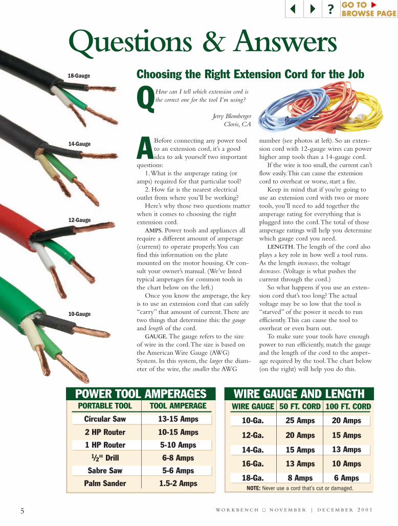
AMPS. Power tools and appliances allrequire a different amount of amperage(current) to operate properly.You canfind this information on the platemounted on the motor housing. Or con-sult your owner’s manual. (We’ve listedtypical amperages for common tools inthe chart below on the left.)
Once you know the amperage, the keyis to use an extension cord that can safely“carry” that amount of current.There aretwo things that determine this: the gaugeand length of the cord.
GAUGE. The gauge refers to the sizeof wire in the cord.The size is based onthe American Wire Gauge (AWG)System. In this system, the larger the diam-eter of the wire, the smaller the AWG
number (see photos at left). So an exten-sion cord with 12-gauge wires can powerhigher amp tools than a 14-gauge cord.
If the wire is too small, the current can’tflow easily.This can cause the extensioncord to overheat or worse, start a fire.
Keep in mind that if you’re going touse an extension cord with two or moretools, you’ll need to add together theamperage rating for everything that isplugged into the cord.The total of thoseamperage ratings will help you determinewhich gauge cord you need.
LENGTH. The length of the cord alsoplays a key role in how well a tool runs.As the length increases, the voltagedecreases. (Voltage is what pushes thecurrent through the cord.)
So what happens if you use an exten-sion cord that’s too long? The actualvoltage may be so low that the tool is“starved” of the power it needs to runefficiently.This can cause the tool tooverheat or even burn out.
To make sure your tools have enoughpower to run efficiently, match the gaugeand the length of the cord to the amper-age required by the tool.The chart below(on the right) will help you do this.
Choosing the Right Extension Cord for the Job
PORTABLE TOOL TOOL AMPERAGE
Circular Saw 13-15 Amps
2 HP Router 10-15 Amps
1 HP Router 5-10 Amps1/2" Drill 6-8 Amps
Sabre Saw 5-6 Amps
Palm Sander 1.5-2 Amps
POWER TOOL AMPERAGES
18-Gauge
14-Gauge
12-Gauge
10-Gauge
WIRE GAUGE 50 FT. CORD 100 FT. CORD
10-Ga. 25 Amps 20 Amps
12-Ga. 20 Amps 15 Amps
14-Ga. 15 Amps 13 Amps
16-Ga. 13 Amps 10 Amps
18-Ga. 8 Amps 6 AmpsNOTE: Never use a cord that’s cut or damaged.
WIRE GAUGE AND LENGTH
Dead WoodFibers
UnwashedTreatedWood
Peeling Paint
6 W O R K B E N C H ■■ N O V E M B E R | D E C E M B E R 2 0 0 1
QI have some treated lumber that I’ve allowedto weather naturally for several months.Now I want to paint it. Is this possible? If
so, what kind of surface preparation should I do?David Rattiganvia the Internet
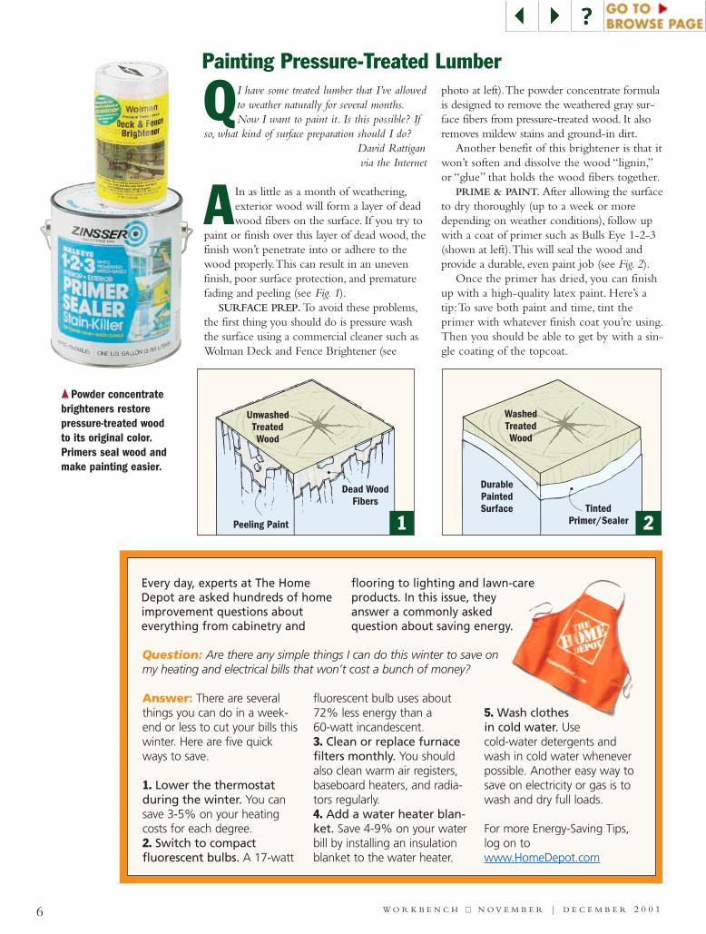
AIn as little as a month of weathering,exterior wood will form a layer of deadwood fibers on the surface. If you try to
paint or finish over this layer of dead wood, thefinish won’t penetrate into or adhere to thewood properly.This can result in an unevenfinish, poor surface protection, and prematurefading and peeling (see Fig. 1).
SURFACE PREP.To avoid these problems,the first thing you should do is pressure washthe surface using a commercial cleaner such asWolman Deck and Fence Brightener (see
photo at left).The powder concentrate formulais designed to remove the weathered gray sur-face fibers from pressure-treated wood. It alsoremoves mildew stains and ground-in dirt.
Another benefit of this brightener is that itwon’t soften and dissolve the wood “lignin,”or “glue” that holds the wood fibers together.
PRIME & PAINT. After allowing the surfaceto dry thoroughly (up to a week or moredepending on weather conditions), follow upwith a coat of primer such as Bulls Eye 1-2-3(shown at left).This will seal the wood andprovide a durable, even paint job (see Fig. 2).
Once the primer has dried, you can finishup with a high-quality latex paint. Here’s atip:To save both paint and time, tint theprimer with whatever finish coat you’re using.Then you should be able to get by with a sin-gle coating of the topcoat.
Painting Pressure-Treated Lumber
DurablePaintedSurface
WashedTreatedWood
TintedPrimer/Sealer
Every day, experts at The HomeDepot are asked hundreds of homeimprovement questions abouteverything from cabinetry and
flooring to lighting and lawn-careproducts. In this issue, theyanswer a commonly askedquestion about saving energy.
Answer: There are severalthings you can do in a week-end or less to cut your bills thiswinter. Here are five quickways to save.
1. Lower the thermostatduring the winter. You cansave 3-5% on your heatingcosts for each degree. 2. Switch to compactfluorescent bulbs. A 17-watt
fluorescent bulb uses about72% less energy than a 60-watt incandescent. 3. Clean or replace furnacefilters monthly. You shouldalso clean warm air registers,baseboard heaters, and radia-tors regularly.4. Add a water heater blan-ket. Save 4-9% on your waterbill by installing an insulationblanket to the water heater.
5. Wash clothesin cold water. Usecold-water detergents andwash in cold water wheneverpossible. Another easy way tosave on electricity or gas is towash and dry full loads.
For more Energy-Saving Tips,log on towww.HomeDepot.com
Question: Are there any simple things I can do this winter to save onmy heating and electrical bills that won’t cost a bunch of money?
1 2
{ Powder concentratebrighteners restore pressure-treated woodto its original color.Primers seal wood andmake painting easier.
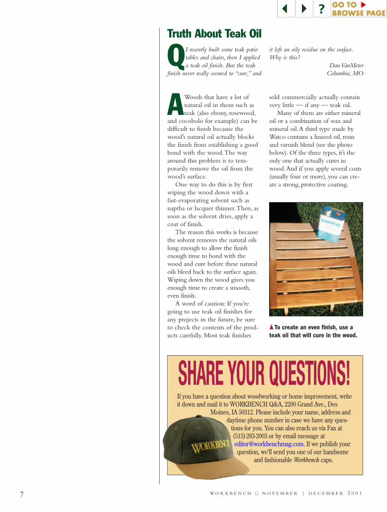
AWoods that have a lot ofnatural oil in them such asteak (also ebony, rosewood,
and cocobolo for example) can bedifficult to finish because thewood’s natural oil actually blocksthe finish from establishing a goodbond with the wood.The wayaround this problem is to tem-porarily remove the oil from thewood’s surface.
One way to do this is by firstwiping the wood down with afast-evaporating solvent such asnaptha or lacquer thinner.Then, assoon as the solvent dries, apply acoat of finish.
The reason this works is becausethe solvent removes the natural oilslong enough to allow the finishenough time to bond with thewood and cure before these naturaloils bleed back to the surface again.Wiping down the wood gives youenough time to create a smooth,even finish.
A word of caution: If you’regoing to use teak oil finishes forany projects in the future, be sureto check the contents of the prod-ucts carefully. Most teak finishes
sold commercially actually containvery little — if any — teak oil.
Many of them are either mineraloil or a combination of wax andmineral oil.A third type made byWatco contains a linseed oil, resinand varnish blend (see the photobelow). Of the three types, it’s theonly one that actually cures inwood.And if you apply several coats(usually four or more), you can cre-ate a strong, protective coating.
Truth About Teak Oil
SSHHAARREE YYOOUURR QQUUEESSTTIIOONNSS!!If you have a question about woodworking or home improvement, writeit down and mail it to WORKBENCH Q&A, 2200 Grand Ave., Des
Moines, IA 50312. Please include your name, address anddaytime phone number in case we have any ques-
tions for you. You can also reach us via Fax at(515)283-2003 or by email message [email protected]. If we publish yourquestion, we’ll send you one of our handsome
and fashionable Workbench caps.
QI recently built some teak patiotables and chairs, then I applieda teak oil finish. But the teak
finish never really seemed to “cure,” and
it left an oily residue on the surface.Why is this?
Dan VanMeterColumbia, MO
{ To create an even finish, use ateak oil that will cure in the wood.
7 W O R K B E N C H ■■ N O V E M B E R | D E C E M B E R 2 0 0 1
8 W O R K B E N C H ■■ N O V E M B E R | D E C E M B E R 2 0 0 1
Tips & Techniques
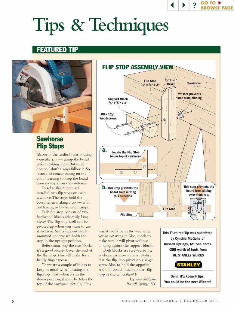
SawhorseFlip Stops It’s one of the cardinal rules of usinga circular saw — clamp the boardbefore making a cut. But to behonest, I don’t always follow it. Soinstead of concentrating on thecut, I’m trying to keep the boardfrom sliding across the sawhorse.
To solve this dilemma, Iinstalled two flip stops on eachsawhorse.The stops hold theboard when making a cut — with-out having to fiddle with clamps.
Each flip stop consists of twohardwood blocks (Assembly View,above).The flip stop itself can bepivoted up when you want to useit (detail a).And a support blockmounted underneath holds thestop in the upright position.
Before attaching the two blocks,it’s a good idea to bevel the end ofthe flip stop.This will make for ahandy finger recess.
There are a couple of things tokeep in mind when locating theflip stop. First, when it’s in thedown position, it must be below thetop of the sawhorse (detail a).This
way, it won’t be in the way whenyou’re not using it.Also, check tomake sure it will pivot withoutbinding against the support block.
Both blocks are screwed to thesawhorse, as shown above. Noticethat the flip stop pivots on a singlescrew.Also, to hold the oppositeend of a board, install another flipstop as shown in detail b.
Cynthia McGahaRussell Springs, KY
FEATURED TIP
This Featured Tip was submittedby Cynthia McGaha of
Russell Springs, KY. She earns$250 worth of tools from
THE STANLEY WORKS
Send Workbench tips.You could be the next Winner!
Support Block#/4 #/4" x " x 3"
Flip Stop#/4 #/4" x " x 3"
#8 x 1Woodscrews
!/2"
Sawhorse
Washer preventsstop from binding
!/2" x "Bevel
!/2
Locate the Flip Stopbelow top of sawhorse
Flip Stop
Flip Stop
This stop prevents theboard from sliding
away from you.
This stop prevents theboard from moving
this direction
a.a.
b.
FLIP STOP ASSEMBLY VIEW
9W O R K B E N C H ■■ N O V E M B E R | D E C E M B E R 2 0 0 1
Do you have a unique way of doingsomething? Just write down your tip
and mail it to:Workbench Tips & Techniques
2200 Grand Ave.Des Moines, IA 50312.
Please include your name, address,and daytime phone number.If you prefer, e-mail us at:
You’ll receive $75-$200 and aWorkbench hat if we publish your tip.
For a free woodworking tip everyweek via e-mail, go to
WoodworkingTips.com.
SHARE YOUR TIPS,JIGS, AND IDEAS
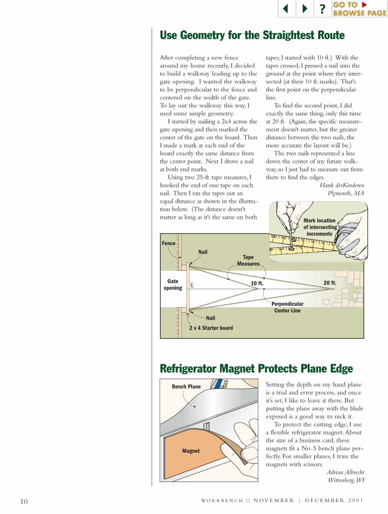
When hanging drywall, sometimesyou have to trim a small amount offthe edge to get a piece to fit. But it’snearly impossible to make a cleanbreak when removing a narrow strip.And if you carve the drywall with aknife, it tears the paper skin.
The solution is to first score thepaper on both sides at the desiredcut line.Then cut a chamfer thatstarts at the cutline and removessome of the gypsum core (Fig.1).Now you can make a crisp, clean cutwithout tearing the paper (Fig. 2).
Not only does this process makeit easy to fit a piece of drywall, ituses the center of the blade (not thepoint).As a result, you get more lifeout of your blades.
Dirk VerSteegRunnells, IA
First:score drywallon cut line.
Second:Chamferedgeswith
utilityknife.
Handy Drywall Tip
1
2
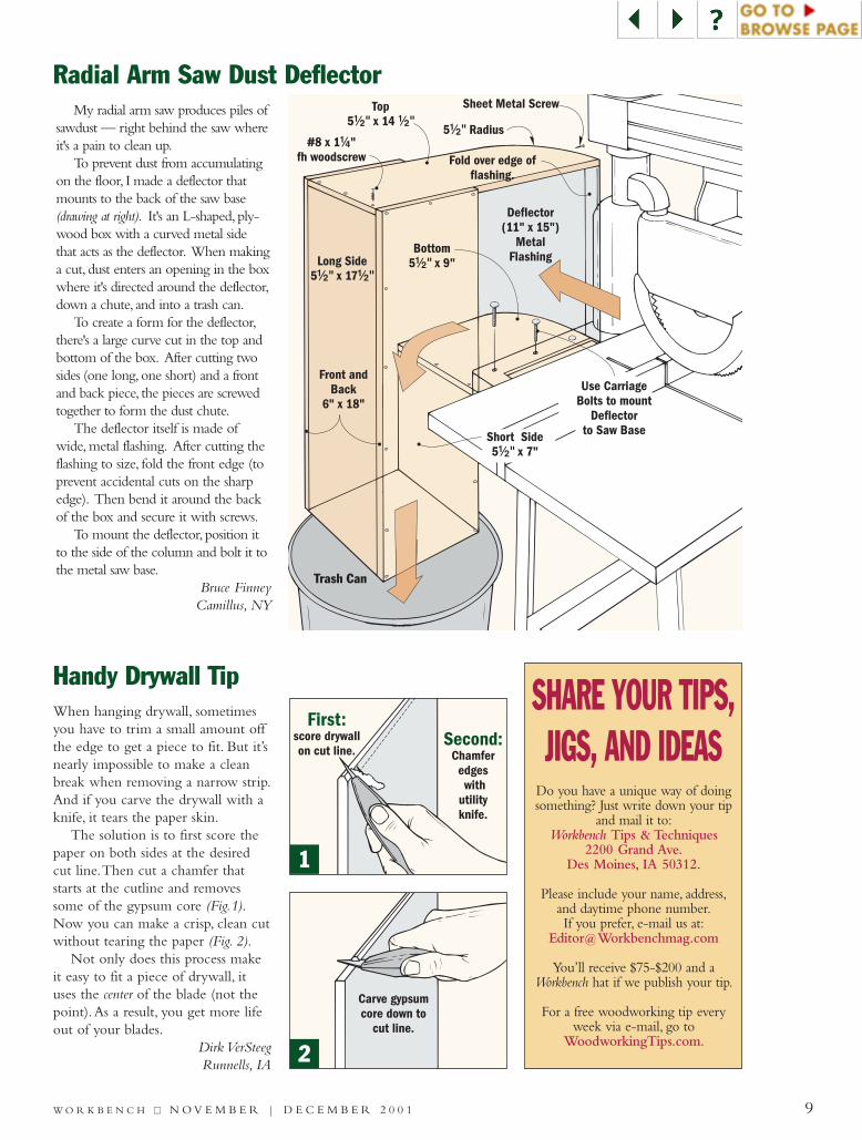
My radial arm saw produces piles ofsawdust — right behind the saw whereit's a pain to clean up.
To prevent dust from accumulatingon the floor, I made a deflector thatmounts to the back of the saw base(drawing at right). It's an L-shaped, ply-wood box with a curved metal sidethat acts as the deflector. When makinga cut, dust enters an opening in the boxwhere it's directed around the deflector,down a chute, and into a trash can.
To create a form for the deflector,there's a large curve cut in the top andbottom of the box. After cutting twosides (one long, one short) and a frontand back piece, the pieces are screwedtogether to form the dust chute.
The deflector itself is made ofwide, metal flashing. After cutting theflashing to size, fold the front edge (toprevent accidental cuts on the sharpedge). Then bend it around the backof the box and secure it with screws.
To mount the deflector, position itto the side of the column and bolt it tothe metal saw base.
Bruce FinneyCamillus, NY
Radial Arm Saw Dust Deflector
Deflector(11" x 15")
MetalFlashing
Use CarriageBolts to mount
Deflectorto Saw Base
Trash Can
Top5 x 14!/2" !/2"
#8 x 1 "fh woodscrew
!/4
Front andBack
6" x 18"
Long Side5 x 17!/2" !/2"
Bottom5 x 9"!/2"
Short Side5 x 7"!/2"
5 Radius!/2"
Sheet Metal Screw
Fold over edge offlashing.
Bench Plane
Magnet
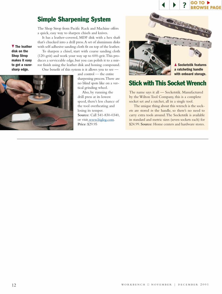
Setting the depth on my hand planeis a trial and error process, and onceit’s set, I like to leave it there. Butputting the plane away with the bladeexposed is a good way to nick it.
To protect the cutting edge, I usea flexible refrigerator magnet.Aboutthe size of a business card, thesemagnets fit a No. 5 bench plane per-fectly. For smaller planes, I trim themagnets with scissors.
Adrian AlbrechtWittenberg,WI
Refrigerator Magnet Protects Plane Edge
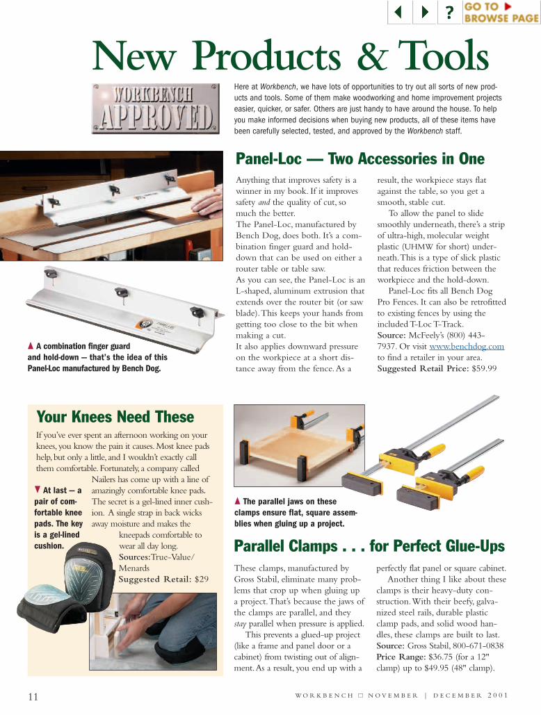
After completing a new fencearound my home recently, I decidedto build a walkway leading up to thegate opening. I wanted the walkwayto be perpendicular to the fence andcentered on the width of the gate.To lay out the walkway this way, Iused some simple geometry.
I started by nailing a 2x4 across thegate opening and then marked thecenter of the gate on the board. ThenI made a mark at each end of theboard exactly the same distance fromthe center point. Next I drove a nailat both end marks.
Using two 25-ft. tape measures, Ihooked the end of one tape on eachnail. Then I ran the tapes out anequal distance as shown in the illustra-tion below. (The distance doesn'tmatter as long as it's the same on both
tapes; I started with 10 ft.) With thetapes crossed, I pressed a nail into theground at the point where they inter-sected (at their 10 ft. marks). That'sthe first point on the perpendicularline.
To find the second point, I didexactly the same thing, only this timeat 20 ft. (Again, the specific measure-ment doesn't matter, but the greaterdistance between the two nails, themore accurate the layout will be.)
The two nails represented a linedown the center of my future walk-way, so I just had to measure out fromthere to find the edges.
Hank derKinderenPlymouth, MA
Use Geometry for the Straightest Route
Mark locationof intersecting
increments
10 W O R K B E N C H ■■ N O V E M B E R | D E C E M B E R 2 0 0 1
11 W O R K B E N C H ■■ N O V E M B E R | D E C E M B E R 2 0 0 1
New Products & Tools
Panel-Loc — Two Accessories in One
Your Knees Need These
Parallel Clamps . . . for Perfect Glue-Ups
{ A combination finger guardand hold-down — that’s the idea of thisPanel-Loc manufactured by Bench Dog.
} At last — apair of com-fortable kneepads. The keyis a gel-linedcushion.
{ The parallel jaws on theseclamps ensure flat, square assem-blies when gluing up a project.
Anything that improves safety is awinner in my book. If it improvessafety and the quality of cut, somuch the better.The Panel-Loc, manufactured byBench Dog, does both. It’s a com-bination finger guard and hold-down that can be used on either arouter table or table saw.As you can see, the Panel-Loc is anL-shaped, aluminum extrusion thatextends over the router bit (or sawblade).This keeps your hands fromgetting too close to the bit whenmaking a cut.It also applies downward pressureon the workpiece at a short dis-tance away from the fence.As a
result, the workpiece stays flatagainst the table, so you get asmooth, stable cut.
To allow the panel to slidesmoothly underneath, there’s a stripof ultra-high, molecular weightplastic (UHMW for short) under-neath.This is a type of slick plasticthat reduces friction between theworkpiece and the hold-down.
Panel-Loc fits all Bench DogPro Fences. It can also be retrofittedto existing fences by using theincluded T-Loc T-Track.Source: McFeely’s (800) 443-7937. Or visit www.benchdog.comto find a retailer in your area.Suggested Retail Price: $59.99
These clamps, manufactured byGross Stabil, eliminate many prob-lems that crop up when gluing upa project.That’s because the jaws ofthe clamps are parallel, and theystay parallel when pressure is applied.
This prevents a glued-up project(like a frame and panel door or acabinet) from twisting out of align-ment.As a result, you end up with a
perfectly flat panel or square cabinet.Another thing I like about these
clamps is their heavy-duty con-struction.With their beefy, galva-nized steel rails, durable plasticclamp pads, and solid wood han-dles, these clamps are built to last.Source: Gross Stabil, 800-671-0838Price Range: $36.75 (for a 12"clamp) up to $49.95 (48" clamp).
If you’ve ever spent an afternoon working on yourknees, you know the pain it causes.Most knee padshelp, but only a little, and I wouldn’t exactly callthem comfortable. Fortunately, a company called
Nailers has come up with a line ofamazingly comfortable knee pads.The secret is a gel-lined inner cush-ion. A single strap in back wicksaway moisture and makes the
kneepads comfortable towear all day long.Sources:True-Value/MenardsSuggested Retail: $29
Here at Workbench, we have lots of opportunities to try out all sorts of new prod-ucts and tools. Some of them make woodworking and home improvement projectseasier, quicker, or safer. Others are just handy to have around the house. To helpyou make informed decisions when buying new products, all of these items havebeen carefully selected, tested, and approved by the Workbench staff.
Simple Sharpening System
Stick with This Socket Wrench
The Shop Strop from Pacific Rack and Machine offersa quick, easy way to sharpen chisels and knives.
It has a leather-covered, MDF disk with a hex shaftthat’s chucked into a drill press.A set of aluminum diskswith self-adhesive sanding cloth fit on top of the leather.
To sharpen a chisel, start with coarse sanding cloth(120-grit) and work your way up to 600-grit.This pro-duces a serviceable edge, but you can polish it to a mir-ror finish using the leather disk and honing compound.
One benefit of this system is it allows you to see —and control — the entiresharpening process.There areno blind spots like on a ver-tical grinding wheel.
Also, by running thedrill press at its lowestspeed, there’s less chance ofthe tool overheating andlosing its temper.Source: Call 541-830-0340,or visit www.bigleg.com.Price: $29.95
The name says it all — Socketstik. Manufacturedby the Wilton Tool Company, this is a completesocket set and a ratchet, all in a single tool.
The unique thing about this wrench is the sock-ets are stored in the handle, so there’s no need tocarry extra tools around.The Socketstik is availablein standard and metric sizes (seven sockets each) for$24.99.Source: Home centers and hardware stores.
} The leatherdisk on theShop Stropmakes it easyto get a razor-sharp edge.
{ Socketstik featuresa ratcheting handlewith onboard storage.
12 W O R K B E N C H ■■ N O V E M B E R | D E C E M B E R 2 0 0 1

DIABLO Blades Deliver High Performance, Low CostIf you were to write up a “wishlist” to include all the things youwant in a saw blade, it would prob-ably read something like this:sharpness, versatility, durability, thinkerf, reasonably priced.
Of course, a blade that deliverson the first four “wishes” couldeasily cost $100 or more.
Which is precisely why Freud’snew Diablo line of saw blades istruly a wish come true for cost-conscious DIY’ers. Simply put,these blades perform as well asblades that cost twice as much.
The list of features on theseblades is impressive. First of all,they’re laser cut, not stamped likemany other blades. In addition toallowing the use of harder, flattersteel, this helps reduce vibrationand noise.It also keeps the bladerunning cool and reduces the risk
of warping. Finally, the blades havea special coating that protects themfrom heat and resin build-up.
Well, a list of features is one thing.But how do the blades perform?
The best testimonial I can give isfor the 12", 72-tooth crosscut blade.We’ve used this blade on the mitersaw in the Workbench shop for over amonth now, making hundreds ofcuts in all types of material.To thisday, the blade cuts as cleanly andeffortlessly as the day it came outof the box — impressive for ablade that only costs $70.
We’ve also been using the 7¼"circular saw blades.These bladeshave a “super thin” kerf (1.5 mm).In part, that explains why the 24-tooth framing blade slices easilythrough pressure-treated lumber(even afer we accidentally cutthrough an embedded nail).As for
the 40-tooth blade, it passed theacid test — making smooth, chip-free crosscuts in oak plywood.Sources: Most home centers Suggested Retail Prices:• D0724 71/4", 24-tooth . . . . $9.99 • D0740 71/4", 40-tooth . . . $19.99• D1040 10", 40-tooth . . . . $34.99• D1244 12", 40-tooth. . . . . $39.99• D1272 12", 72 tooth. . . . . $69.99
{ Diablo bladesare available inthree standardcontractor sizes:71/4" (24- and 40-tooth versions),10", and 12".
13W O R K B E N C H ■■ N O V E M B E R | D E C E M B E R 2 0 0 1
W
14 W O R K B E N C H ■■ N O V E M B E R | D E C E M B E R 2 0 0 1
WORKBENCHinteractive.com
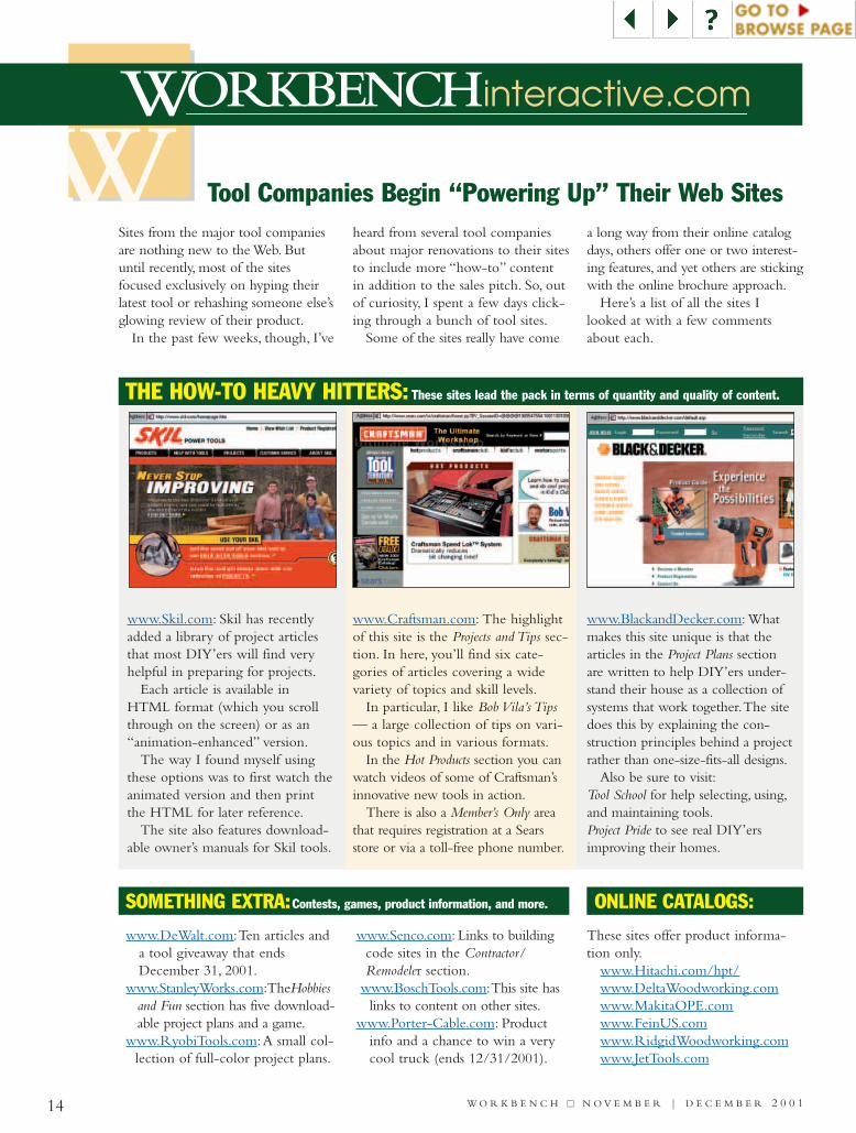
Tool Companies Begin “Powering Up” Their Web Sites
www.DeWalt.com:Ten articles anda tool giveaway that endsDecember 31, 2001.
www.StanleyWorks.com:TheHobbiesand Fun section has five download-able project plans and a game.
www.RyobiTools.com:A small col-lection of full-color project plans.
www.Senco.com: Links to buildingcode sites in the Contractor/Remodeler section.
www.BoschTools.com:This site haslinks to content on other sites.
www.Porter-Cable.com: Productinfo and a chance to win a verycool truck (ends 12/31/2001).
These sites offer product informa-tion only.
www.Hitachi.com/hpt/www.DeltaWoodworking.comwww.MakitaOPE.comwww.FeinUS.comwww.RidgidWoodworking.comwww.JetTools.com
Sites from the major tool companiesare nothing new to the Web. Butuntil recently, most of the sitesfocused exclusively on hyping theirlatest tool or rehashing someone else’sglowing review of their product.
In the past few weeks, though, I’ve
heard from several tool companiesabout major renovations to their sitesto include more “how-to” contentin addition to the sales pitch. So, outof curiosity, I spent a few days click-ing through a bunch of tool sites.
Some of the sites really have come
a long way from their online catalogdays, others offer one or two interest-ing features, and yet others are stickingwith the online brochure approach.
Here’s a list of all the sites Ilooked at with a few commentsabout each.
www.Skil.com: Skil has recentlyadded a library of project articlesthat most DIY’ers will find veryhelpful in preparing for projects.
Each article is available inHTML format (which you scrollthrough on the screen) or as an“animation-enhanced” version.
The way I found myself usingthese options was to first watch theanimated version and then printthe HTML for later reference.
The site also features download-able owner’s manuals for Skil tools.
www.Craftsman.com: The highlightof this site is the Projects and Tips sec-tion. In here, you’ll find six cate-gories of articles covering a widevariety of topics and skill levels.
In particular, I like Bob Vila’s Tips— a large collection of tips on vari-ous topics and in various formats.
In the Hot Products section you canwatch videos of some of Craftsman’sinnovative new tools in action.
There is also a Member’s Only areathat requires registration at a Searsstore or via a toll-free phone number.
www.BlackandDecker.com: Whatmakes this site unique is that thearticles in the Project Plans sectionare written to help DIY’ers under-stand their house as a collection ofsystems that work together.The sitedoes this by explaining the con-struction principles behind a projectrather than one-size-fits-all designs.
Also be sure to visit:Tool School for help selecting, using,and maintaining tools.Project Pride to see real DIY’ersimproving their homes.
These sites lead the pack in terms of quantity and quality of content.
Contests, games, product information, and more.
THE HOW-TO HEAVY HITTERS:
SOMETHING EXTRA: ONLINE CATALOGS:
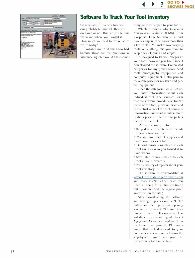
Software To Track Your Tool InventoryChances are, if I name a tool youcan probably tell me whether youown one or not. But can you tell mewhen and where you bought it?How much you paid for it? What it’sworth today?
Probably not. And that’s too bad,because those are the questions aninsurance adjuster would ask if some-
thing were to happen to your tools.Which is exactly why Equipment
Management Software (EMS) fromCorporate Edge Software is a musthave for anyone who owns more thana few tools. EMS makes inventoryingtools, or anything else you want tokeep track of, quick and simple.
It’s designed to let you categorizeyour tools however you like. Since Idownloaded the software, I’ve createdcategories for my power tools, handtools, photography equipment, andcomputer equipment. I also plan tomake categories for my lawn and gar-den equipment.
Once the categories are all set up,you enter information about eachindividual tool. The standard formthat the software provides asks for thename of the tool, purchase price anddate, actual value of the tool, warrantyinformation, and serial number.Thereis also a place on the form to paste apicture of the tool.
EMS also allows you to:• Keep detailed maintenance records
on every tool you own.• Manage inventory of supplies and
accessories for each tool.• Record transactions related to each
tool (such as who you loaned it toand when).
• Save internet links related to eachtool in your inventory.
• Print a variety of reports about yourtool inventory.
The software is downloadable atwww.CorporateEdgeSoftware.comand costs $17.95. (That price waslisted as being for a “limited time,”but I couldn’t find the regular priceanywhere on the site.)
After downloading the softwareand starting it up, click on the “Help”button on the top of the openingscreen. Now select “Online UserGuide” from the pulldown menu.Thiswill direct you to a list of guides. SelectEquipment Management Software fromthe list and then print the PDF user’sguide that will download to yourcomputer in a few minutes.Follow thestep-by-step guide and you’ll beinventorying tools in no time.
15 W O R K B E N C H ■■ N O V E M B E R | D E C E M B E R 2 0 0 1
W O R K B E N C H ■■ N O V E M B E R | D E C E M B E R 2 0 0 116
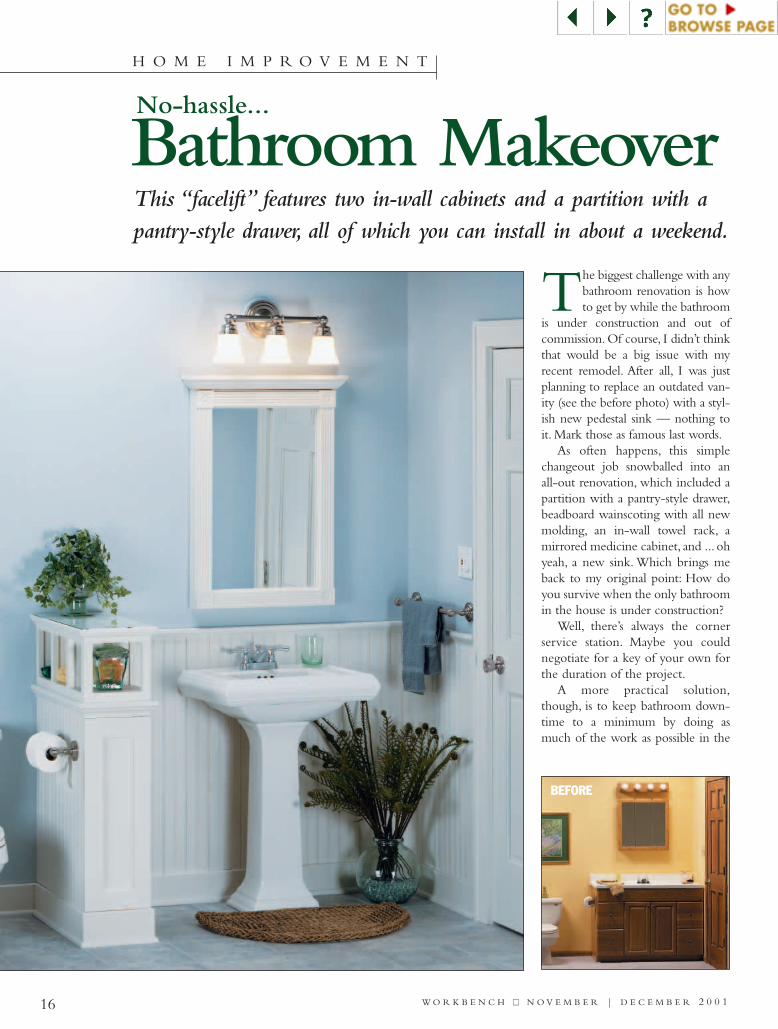
Bathroom MakeoverThis “facelift” features two in-wall cabinets and a partition with apantry-style drawer, all of which you can install in about a weekend.
The biggest challenge with anybathroom renovation is howto get by while the bathroom
is under construction and out ofcommission. Of course, I didn’t thinkthat would be a big issue with myrecent remodel. After all, I was justplanning to replace an outdated van-ity (see the before photo) with a styl-ish new pedestal sink — nothing toit. Mark those as famous last words.
As often happens, this simplechangeout job snowballed into anall-out renovation, which included apartition with a pantry-style drawer,beadboard wainscoting with all newmolding, an in-wall towel rack, amirrored medicine cabinet, and ... ohyeah, a new sink. Which brings meback to my original point: How doyou survive when the only bathroomin the house is under construction?
Well, there’s always the cornerservice station. Maybe you couldnegotiate for a key of your own forthe duration of the project.
A more practical solution,though, is to keep bathroom down-time to a minimum by doing asmuch of the work as possible in the
H O M E I M P R O V E M E N T
BEFORE
No-hassle...
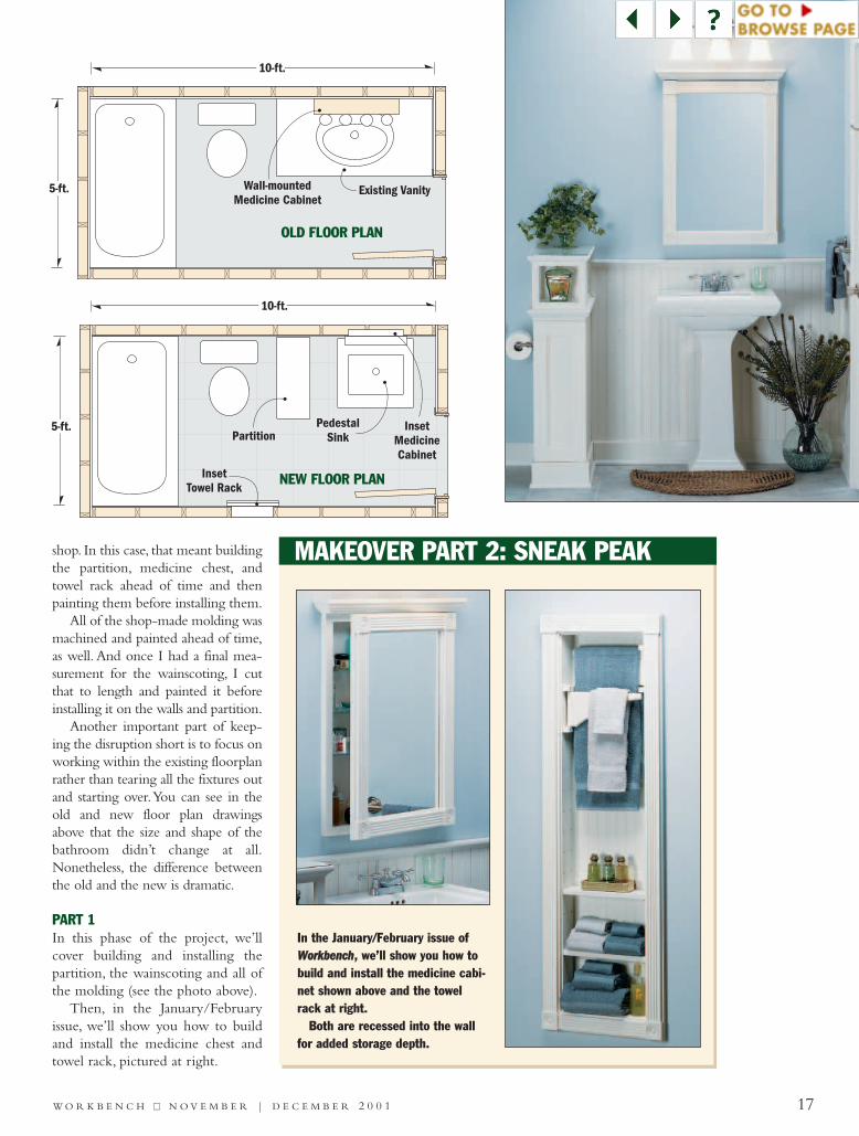
5-ft.
10-ft.
Existing VanityWall-mountedMedicine Cabinet
OLD FLOOR PLAN
5-ft.Partition
10-ft.
InsetTowel Rack
InsetMedicineCabinet
PedestalSink
NEW FLOOR PLAN
W O R K B E N C H ■■ N O V E M B E R | D E C E M B E R 2 0 0 1 17
shop. In this case, that meant buildingthe partition, medicine chest, andtowel rack ahead of time and thenpainting them before installing them.
All of the shop-made molding wasmachined and painted ahead of time,as well. And once I had a final mea-surement for the wainscoting, I cutthat to length and painted it beforeinstalling it on the walls and partition.
Another important part of keep-ing the disruption short is to focus onworking within the existing floorplanrather than tearing all the fixtures outand starting over.You can see in theold and new floor plan drawingsabove that the size and shape of thebathroom didn’t change at all.Nonetheless, the difference betweenthe old and the new is dramatic.
PART 1In this phase of the project, we’llcover building and installing thepartition, the wainscoting and all ofthe molding (see the photo above).
Then, in the January/Februaryissue, we’ll show you how to buildand install the medicine chest andtowel rack, pictured at right.
MAKEOVER PART 2: SNEAK PEAK
In the January/February issue ofWWoorrkkbbeenncchh, we’ll show you how tobuild and install the medicine cabi-net shown above and the towelrack at right.
Both are recessed into the wallfor added storage depth.
18 W O R K B E N C H ■■ N O V E M B E R | D E C E M B E R 2 0 0 1
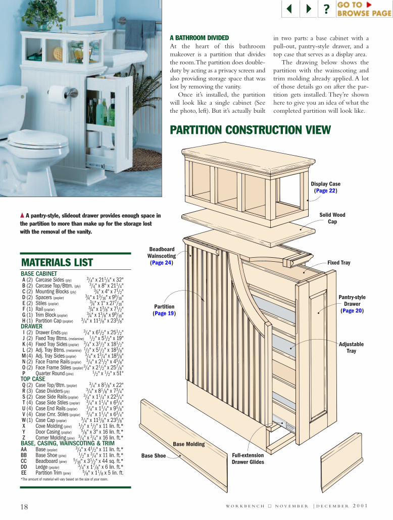
A BATHROOM DIVIDEDAt the heart of this bathroommakeover is a partition that dividesthe room.The partition does double-duty by acting as a privacy screen andalso providing storage space that waslost by removing the vanity.
Once it’s installed, the partitionwill look like a single cabinet (Seethe photo, left). But it’s actually built
in two parts: a base cabinet with apull-out, pantry-style drawer, and atop case that serves as a display area.
The drawing below shows thepartition with the wainscoting andtrim molding already applied. A lotof those details go on after the par-tition gets installed. They’re shownhere to give you an idea of what thecompleted partition will look like.
Base Shoe Full-extensionDrawer Glides
Base Molding
BeadboardWainscoting(Page 24)
Display Case(Page 22)
Solid WoodCap
Fixed Tray
Partition(Page 19)
Pantry-styleDrawer
(Page 20)
AdjustableTray
BASE CABINETA (2) Carcase Sides (ply) 3/4" x 211/4" x 32"B (2) Carcase Top/Bttm. (ply) 3/4" x 8" x 211/4"C (2) Mounting Blocks (ply) 3/4" x 4" x 71/2"D (2) Spacers (poplar) 3/4" x 13/16" x 99/16"E (2) Stiles (poplar) 3/4" x 1" x 277/16"F (1) Rail (poplar) 3/4" x 13/8" x 71/2"G (1) Trim Block (poplar) 3/4" x 13/8" x 99/16"H (1) Partition Cap (poplar) 3/4" x 113/8" x 235/8"DRAWERI (2) Drawer Ends (ply) 3/4" x 61/2" x 251/2"J (2) Fixed Tray Btms. (melamine) 1/2" x 51/2" x 19"K (4) Fixed Tray Sides (poplar) 3/4" x 31/2" x 181/2"L (2) Adj. Tray Btms. (melamine) 1/2" x 51/2" x 183/8"M (4) Adj. Tray Sides (poplar) 3/4" x 13/4" x 183/8" N (2) Face Frame Rails (poplar) 3/4" x 21/2" x 45/8"O (2) Face Frame Stiles (poplar)3/4" x 21/2" x 257/8"P Quarter Round (pine) 1/2" x 1/2" x 51"TOP CASEQ (2) Case Top/Btm. (poplar) 3/4" x 81/8" x 22"R (3) Case Dividers (ply) 3/4" x 81/8" x 73/4"S (2) Case Side Rails (poplar) 3/4" x 11/4" x 223/4"T (4) Case Side Stiles (poplar) 3/4" x 11/4" x 63/4"U (4) Case End Rails (poplar) 3/4" x 11/4" x 95/8"V (4) Case Crnr. Stiles (poplar) 3/4" x 11/4" x 63/4"W (1) Case Cap (poplar) 3/4" x 113/8" x 235/8"X Cove Molding (pine) 1/2" x 1/2" x 11 lin. ft.*Y Door Casing (poplar) 5/8" x 3" x 16 lin. ft.*Z Corner Molding (pine) 3/4" x 3/4" x 16 lin. ft.*
BASE, CASING, WAINSCOTING & TRIMAA Base (poplar) 3/4" x 41/2" x 11 lin. ft.*BB Base Shoe (pine) 1/2" x 3/4" x 11 lin. ft.*CC Beadboard (pine) 5/16" x 31/2" x 44 sq. ft.*DD Ledge (poplar) 3/4" x 17/8" x 6 lin. ft.*EE Partition Trim (pine) 5/8" x 11/8 x 5 lin. ft.*The amount of material will vary based on the size of your room.
MATERIALS LIST
PARTITION CONSTRUCTION VIEW
{{ A pantry-style, slideout drawer provides enough space inthe partition to more than make up for the storage lostwith the removal of the vanity.
PartitionCap
H
CarcaseSide
CarcaseBottom
B
Carcase TopB
MountingBlocks
C
CarcaseSide
TrimBlock
G
RailF
StilesE
SpacersD
A
A
6d Finish Nail
6d FinishNail
#8 x 1Fh Woodscrew
!/2"
W O R K B E N C H ■■ N O V E M B E R | D E C E M B E R 2 0 0 1 19
CARCASE CONSTRUCTION
ACC
E
CarcaseSide
Beadboard
Stile
A Carcase Side
#/4" Dado Blade
Rip Fence
A Carcase Side
Dado Blade#/4"
Auxiliary Fence
3 "&/8 #/4"
!/4"
TOP CORNER DETAIL
#/4"
Auxiliary Fence
!/4"
CarcaseSide
A
a.
a.
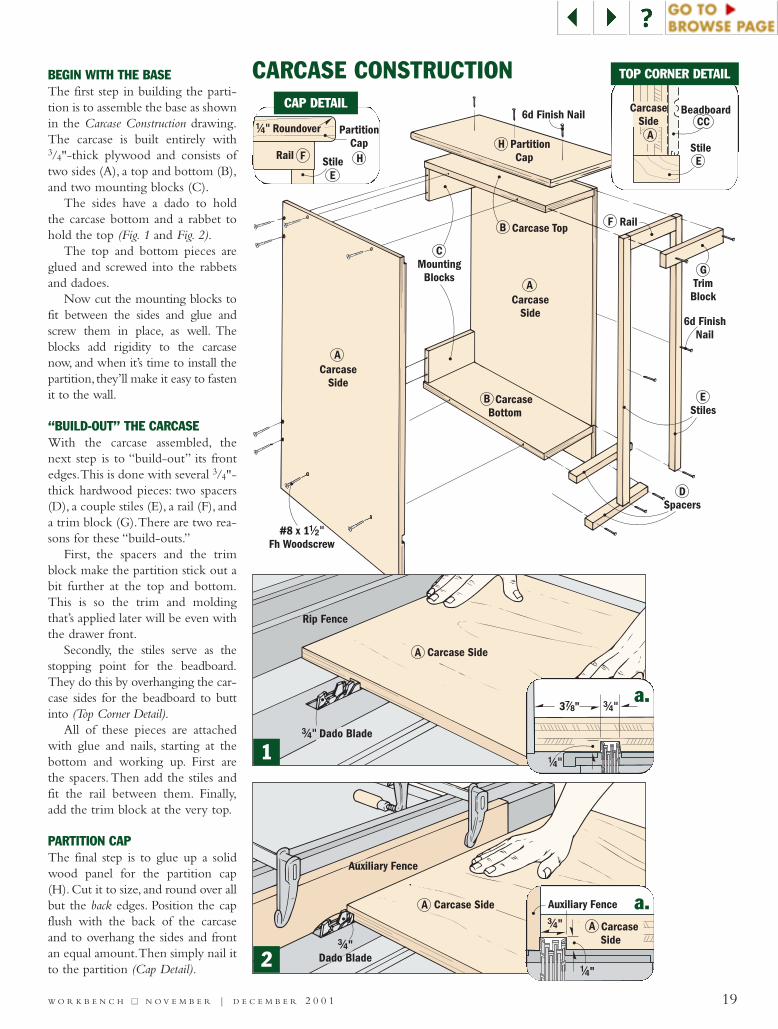
BEGIN WITH THE BASEThe first step in building the parti-tion is to assemble the base as shownin the Carcase Construction drawing.The carcase is built entirely with3/4"-thick plywood and consists oftwo sides (A), a top and bottom (B),and two mounting blocks (C).
The sides have a dado to holdthe carcase bottom and a rabbet tohold the top (Fig. 1 and Fig. 2).
The top and bottom pieces areglued and screwed into the rabbetsand dadoes.
Now cut the mounting blocks tofit between the sides and glue andscrew them in place, as well. Theblocks add rigidity to the carcasenow, and when it’s time to install thepartition, they’ll make it easy to fastenit to the wall.
“BUILD-OUT” THE CARCASEWith the carcase assembled, thenext step is to “build-out” its frontedges.This is done with several 3/4"-thick hardwood pieces: two spacers(D), a couple stiles (E), a rail (F), anda trim block (G).There are two rea-sons for these “build-outs.”
First, the spacers and the trimblock make the partition stick out abit further at the top and bottom.This is so the trim and moldingthat’s applied later will be even withthe drawer front.
Secondly, the stiles serve as thestopping point for the beadboard.They do this by overhanging the car-case sides for the beadboard to buttinto (Top Corner Detail).
All of these pieces are attachedwith glue and nails, starting at thebottom and working up. First arethe spacers.Then add the stiles andfit the rail between them. Finally,add the trim block at the very top.
PARTITION CAPThe final step is to glue up a solidwood panel for the partition cap(H). Cut it to size, and round over allbut the back edges. Position the capflush with the back of the carcaseand to overhang the sides and frontan equal amount.Then simply nail itto the partition (Cap Detail).
1
2
PartitionCap
E
F HRail Stile
!/4" Roundover
CAP DETAIL
PartitionCarcase
Drawer EndI
J
K
LM
Drawer Slide
Fixed Tray Bottom
2 "#/4Fixed Tray
Side
K
J
LM Adj. Tray
Bottom
Adj. TraySide
I Drawer End
#8 x 1Fh Woodscrew
!/4"
#8 x 1Fh Woodscrews
!/2"
Face Frame
#8 x 1Fh Woodscrews
!/2"
Shelf Pin
W O R K B E N C H ■■ N O V E M B E R | D E C E M B E R 2 0 0 120
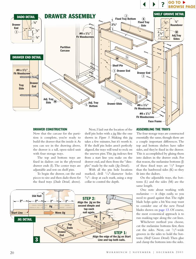
DRAWER CONSTRUCTIONNow that the carcase for the parti-tion is complete, you’re ready tobuild the drawer that fits inside it.Asyou can see in the drawing above,the drawer is a tall, open-sided unitwith four storage trays.
The top and bottom trays arefixed in dadoes cut in the plywooddrawer ends (I).The center trays areadjustable and rest on shelf pins.
To begin the drawer, cut the endpieces to size and then dado them forthe fixed trays (Dado Detail, above).
Next, I laid out the location of theshelf pin holes with a jig like the oneshown in Figure 3. Making this jigtakes a few minutes, but it’s worth it.If the shelf pin holes aren’t perfectlyaligned, the trays will tend to rock onthe uneven pins.This jig indexes firstfrom a start line you make on thedrawer end, and then from the “dim-ples” made by the nails ( Jig Detail ).
With all the pin hole locationsmarked, drill 1/4"-diameter holes3/8"- deep at each mark, using a stopcollar to control the depth.
ASSEMBLING THE TRAYSThe four storage trays are constructedessentially the same, though there area couple important differences. Thetop and bottom shelves have tallersides, and they’re fixed in the drawer.This is accomplished by gluing theminto dadoes in the drawer ends. Forthat reason, the melamine bottoms (J)of these fixed trays are 1/2" longerthan the hardwood sides (K) so theyfit into the dadoes.
On the adjustable trays, the bot-toms (L) and the sides (M) are thesame length.
One note about working withmelamine — it chips easily, so youneed to guard against that.The rightblade helps quite a bit.You may wantto consider one of the new Freudblades shown on page 13. Of course,the most economical approach is torun masking tape along the cut lines.
Whichever method you choose,cut the melamine bottoms first, thencut the sides. Next, cut 1/2"-widegrooves in the sides to hold the bot-toms (Shelf Groove Detail).Then glueand clamp the bottoms into the sides.
DRAWER ASSEMBLY
Jig
IDrawer
End
TopDado
STEP 1:Align the edge of the jig on Start
Line and tap both nails.
STEP 2:Align the jig on thesecond dimple and
tap eachnail again.
1"
I !/2"
DrawerEnd
!/4"
!/4"
2"
Move JigStart Line
16d Nail
2" 2" 2"
Jig
2"2"
DADO DETAIL !/4"
Roundover!/4"
M!/2"
Adj.TraySides!/4"
SHELF GROOVE DETAIL
3
#8 x 1Fh Woodscrew
!/2"
DrawerEndTray
Side
DRAWER END DETAIL
JIG DETAIL
Face FrameStile
Face FrameRail
!/2 !/2" x "Quarter Round
Molding
O
N
N
P
Drawer Slide
FingerRecess
FIRST:Attach Face Frame(see Figs. 4 and 5)
SECOND: Miter Quarter Round to fit inside Face Frame.
O
IDrawer End
W O R K B E N C H ■■ N O V E M B E R | D E C E M B E R 2 0 0 1 21
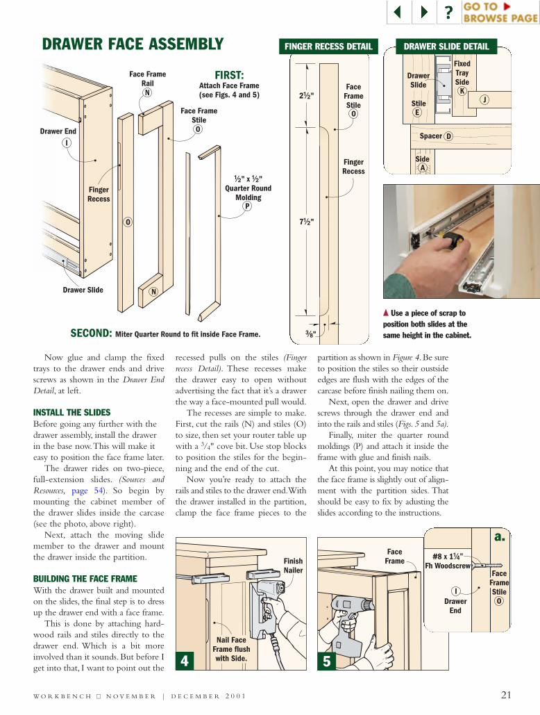
Now glue and clamp the fixedtrays to the drawer ends and drivescrews as shown in the Drawer EndDetail, at left.
INSTALL THE SLIDESBefore going any further with thedrawer assembly, install the drawerin the base now.This will make iteasy to position the face frame later.
The drawer rides on two-piece,full-extension slides. (Sources andResources, page 54). So begin bymounting the cabinet member ofthe drawer slides inside the carcase(see the photo, above right).
Next, attach the moving slidemember to the drawer and mountthe drawer inside the partition.
BUILDING THE FACE FRAMEWith the drawer built and mountedon the slides, the final step is to dressup the drawer end with a face frame.
This is done by attaching hard-wood rails and stiles directly to thedrawer end. Which is a bit moreinvolved than it sounds. But before Iget into that, I want to point out the
recessed pulls on the stiles (Fingerrecess Detail). These recesses makethe drawer easy to open withoutadvertising the fact that it’s a drawerthe way a face-mounted pull would.
The recesses are simple to make.First, cut the rails (N) and stiles (O)to size, then set your router table upwith a 3/4" cove bit. Use stop blocksto position the stiles for the begin-ning and the end of the cut.
Now you’re ready to attach therails and stiles to the drawer end.Withthe drawer installed in the partition,clamp the face frame pieces to the
partition as shown in Figure 4.Be sureto position the stiles so their oustsideedges are flush with the edges of thecarcase before finish nailing them on.
Next, open the drawer and drivescrews through the drawer end andinto the rails and stiles (Figs.5 and 5a).
Finally, miter the quarter roundmoldings (P) and attach it inside theframe with glue and finish nails.
At this point, you may notice thatthe face frame is slightly out of align-ment with the partition sides. Thatshould be easy to fix by adusting theslides according to the instructions.
DRAWER FACE ASSEMBLY
FinishNailer
Nail FaceFrame flushwith Side.
{{ Use a piece of scrap toposition both slides at thesame height in the cabinet.
FaceFrame
4 5
FaceFrameStileI
O
#8 x 1Fh Woodscrew
!/4"
DrawerEnd
FaceFrameStile
FingerRecess
O
2 "!/2
7 "!/2
#/8"
FixedTraySide
E
Side
Spacer
Stile
DrawerSlide
K
A
D
J
FINGER RECESS DETAIL
a.
DRAWER SLIDE DETAIL
Partition Carcase#8 x 1 "Fh Woodscrew
!/2
#8 x 1 "Fh Woodscrew
!/2
6d FinishNail
Case SideStile
T
Case CornerStile
VCase Corner
Stile
V
CaseDividers
R
CaseEndRails
UT
CoveMoldingX
CoveMoldingX
Case Side RailS
Case CapW
Case TopQ
Case BottomQ
T
T
V
V
6!/2"
6!/2"
6d Finish Nail
Miter Endof Cove Molding
W O R K B E N C H ■■ N O V E M B E R | D E C E M B E R 2 0 0 122
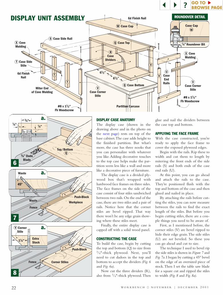
DISPLAY CASE ANATOMYThe display case (shown in thedrawing above and in the photo onthe next page) rests on top of thebase cabinet.The case adds height tothe finished partition. But what’smore, the case has three nooks thatyou can personalize with whateveryou like. Adding decorative touchesto the top case helps make the par-tition seem less like a wall and morelike a decorative piece of furniture.
The display case is a divided ply-wood box that’s wrapped withhardwood face frames on three sides.The face frames on the side of thecase consist of four stiles sandwichedbetween two rails. On the end of thecase, there are two stiles and a pair ofrails. Notice here that the cornerstiles are bevel ripped. That waythere won’t be any edge grain show-ing where these stiles meet.
Finally, the entire display case iscapped off with a solid wood panel.
CONSTRUCTING THE CASETo build the case, begin by cuttingthe top and bottom (Q) to size from3/4"-thick plywood. Next, you’llneed to cut dadoes in the top andbottom to accept the dividers (Fig. 6and Fig. 6a).
Now cut the three dividers (R),also from 3/4"-thick plywood.Then
glue and nail the dividers betweenthe case top and bottom.
APPLYING THE FACE FRAMEWith the case constructed, you’reready to apply the face frame tocover the exposed plywood edges.
Begin with the rails. Rip these towidth and cut them to length bymitering the front ends of the siderails (S) and both ends of the caseend rails (U).
At this point, you can go aheadand attach the rails to the case.They’re positioned flush with thetop and bottom of the case and thenglued and nailed in place.
By attaching the rails before cut-ting the stiles, you can now measurebetween the rails to find the exactlength of the stiles. But before youbegin cutting stiles, there are a cou-ple things you need to be aware of.
First, as I mentioned before, thecorner stiles (V) are bevel ripped tohide their edge grain.The side stiles(U) are not beveled. So these youcan go ahead and cut to size.
The technique I used to bevel ripthe side stiles is shown in Figure 7 andFig. 7a. I began by cutting a 45° bevelon the edge of an oversized piece ofstock.Then I set the table saw bladefor a square cut and ripped the stilesto width (Fig. 8 and Fig. 8a).
DISPLAY UNIT ASSEMBLY
QTop/Bottom
#/4" DadoBlade
Fence
Push-BlockWaste Workpiece
CaseCorner StilesFence
Push-Block
#/4"!/4"
!/4"
!/4" Roundover Bit
WCase Cap
Waste
45º
ExtraStock
V CornerStile
1 "!/4
a.
a.
a.
ROUNDOVER DETAIL
6
7
8
W O R K B E N C H ■■ N O V E M B E R | D E C E M B E R 2 0 0 1 23
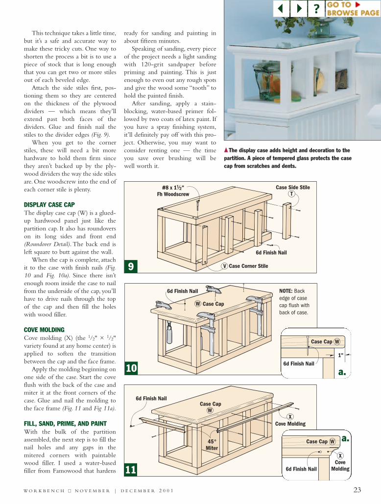
This technique takes a little time,but it’s a safe and accurate way tomake these tricky cuts. One way toshorten the process a bit is to use apiece of stock that is long enoughthat you can get two or more stilesout of each beveled edge.
Attach the side stiles first, pos-tioning them so they are centeredon the thickness of the plywooddividers — which means they’llextend past both faces of thedividers. Glue and finish nail thestiles to the divider edges (Fig. 9).
When you get to the cornerstiles, these will need a bit morehardware to hold them firm sincethey aren’t backed up by the ply-wood dividers the way the side stilesare. One woodscrew into the end ofeach corner stile is plenty.
DISPLAY CASE CAPThe display case cap (W) is a glued-up hardwood panel just like thepartition cap. It also has roundoverson its long sides and front end(Roundover Detail). The back end isleft square to butt against the wall.
When the cap is complete, attachit to the case with finish nails (Fig.10 and Fig. 10a). Since there isn’tenough room inside the case to nailfrom the underside of the cap, you’llhave to drive nails through the topof the cap and then fill the holeswith wood filler.
COVE MOLDINGCove molding (X) (the 1/2" × 1/2"variety found at any home center) isapplied to soften the transitionbetween the cap and the face frame.
Apply the molding beginning onone side of the case. Start the coveflush with the back of the case andmiter it at the front corners of thecase. Glue and nail the molding tothe face frame (Fig. 11 and Fig 11a).
FILL, SAND, PRIME, AND PAINTWith the bulk of the partitionassembled, the next step is to fill thenail holes and any gaps in themitered corners with paintablewood filler. I used a water-basedfiller from Famowood that hardens
ready for sanding and painting inabout fifteen minutes.
Speaking of sanding, every pieceof the project needs a light sandingwith 120-grit sandpaper beforepriming and painting. This is justenough to even out any rough spotsand give the wood some “tooth” tohold the painted finish.
After sanding, apply a stain-blocking, water-based primer fol-lowed by two coats of latex paint. Ifyou have a spray finishing system,it’ll definitely pay off with this pro-ject. Otherwise, you may want toconsider renting one — the timeyou save over brushing will be well worth it.
{{The display case adds height and decoration to thepartition. A piece of tempered glass protects the casecap from scratches and dents.
6d Finish Nail
Case CapW
Case Cap
CoveMolding6d Finish Nail
W
X
1"
Case Cap
6d Finish Nail
W
10
9
11
a.
a.
NOTE: Backedge of case cap flush withback of case.
#8 x 2Fh Woodscrew
!/2"
Partition2x4 Cleat,Attachedto Floor
Base Shoe
BaseAA
BB
CC
DD
X
BeadboardWainscoting
Ledge
Cove
DisplayCase
W O R K B E N C H ■■ N O V E M B E R | D E C E M B E R 2 0 0 124
PARTITION POSITIONThere’s no hard-and-fast rule aboutwhere to locate the partition in your
bathroom. Centered between thesink and the toilet
seems natural, butyou may decide you
want more space on oneside or the other.One other quick note, if
you’re replacing the flooringin the bathroom, that should be
done before installing the partition.
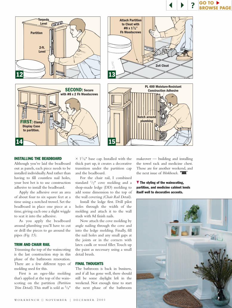
FASTENING THE PARTITIONWhen you’ve found just the right spotfor the partition, square it to the walland level it as shown in Figure 12.Next,attach a 2x4 cleat to the floor andscrew the cabinet to the cleat (Fig. 13).
Now fasten the display case to thepartition with woodscrews drivenfrom inside the cabinet (Fig. 14).Thenfasten the cabinet to the wall. If you’relucky enough to have a wall stud thatfalls within the width of the partition,a couple of woodscrews through eachbacker block into the stud will do the
job nicely. Otherwise, you’ll need touse a toggle bolt in each block.
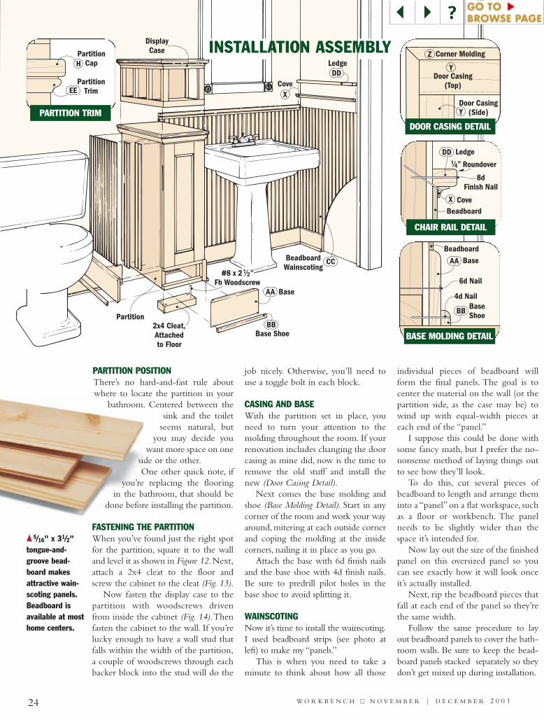
CASING AND BASEWith the partition set in place, youneed to turn your attention to themolding throughout the room. If yourrenovation includes changing the doorcasing as mine did, now is the time toremove the old stuff and install thenew (Door Casing Detail).
Next comes the base molding andshoe (Base Molding Detail). Start in anycorner of the room and work your wayaround, mitering at each outside cornerand coping the molding at the insidecorners, nailing it in place as you go.
Attach the base with 6d finish nailsand the base shoe with 4d finish nails.Be sure to predrill pilot holes in thebase shoe to avoid splitting it.
WAINSCOTINGNow it’s time to install the wainscoting.I used beadboard strips (see photo atleft) to make my “panels.”
This is when you need to take aminute to think about how all those
individual pieces of beadboard willform the final panels. The goal is tocenter the material on the wall (or thepartition side, as the case may be) towind up with equal-width pieces ateach end of the “panel.”
I suppose this could be done withsome fancy math, but I prefer the no-nonsense method of laying things outto see how they’ll look.
To do this, cut several pieces ofbeadboard to length and arrange theminto a “panel” on a flat workspace, suchas a floor or workbench. The panelneeds to be slightly wider than thespace it’s intended for.
Now lay out the size of the finishedpanel on this oversized panel so youcan see exactly how it will look onceit’s actually installed.
Next, rip the beadboard pieces thatfall at each end of the panel so they’rethe same width.
Follow the same procedure to layout beadboard panels to cover the bath-room walls. Be sure to keep the bead-board panels stacked separately so theydon’t get mixed up during installation.
PartitionCap
PartitionTrimEE
H
Ledge
8dFinish Nail
Cove
DD
XBeadboard
!/4" Roundover
Base
6d Nail
4d NailBaseShoe
AA
BB
Beadboard
Corner MoldingZ
Y
Y
Door Casing(Top)
Door Casing(Side)
{{ 5/16" x 31/2"tongue-and-groove bead-board makesattractive wain-scoting panels.Beadboard isavailable at mosthome centers.
PARTITION TRIM
CHAIR RAIL DETAIL
BASE MOLDING DETAIL
DOOR CASING DETAIL
INSTALLATION ASSEMBLY
W O R K B E N C H ■■ N O V E M B E R | D E C E M B E R 2 0 0 1 37
INSTALLING THE BEADBOARDAlthough you’ve laid the beadboardout as panels, each piece needs to beinstalled individually.And rather thanhaving to fill countless nail holes,your best bet is to use constructionadhesive to install the beadboard.
Apply the adhesive over an areaof about four to six square feet at atime using a notched trowel. Set thebeadboard in place one piece at atime, giving each one a slight wiggleto seat it into the adhesive.
As you apply the beadboardaround plumbing you’ll have to cutor drill the pieces to go around thepipes (Fig. 15).
TRIM AND CHAIR RAILTrimming the top of the wainscotingis the last construction step in thisphase of the bathroom renovation.There are a few different types ofmolding used for this.
First is an ogee-like moldingthat’s applied at the top of the wain-scoting on the partition (PartitionTrim Detail).This stuff is sold as 5/8"
× 11/8" base cap. Installed with thethick part up, it creates a decorativetransition under the partition capand the beadboard.
For the chair rail, I combinedstandard 1/2" cove molding and ashop-made ledge (DD) molding toadd some dimension to the top ofthe wall covering (Chair Rail Detail).
Install the ledge first. Drill pilotholes through the width of themolding and attach it to the wallstuds with 8d finish nails.
Now attach the cove molding byangle nailing through the cove andinto the ledge molding. Finally, fillthe nail holes and any small gaps atthe joints or in the corners withlatex caulk or wood filler.Touch upthe paint as necessary using a smalldetail brush.
FINAL THOUGHTSThe bathroom is back in business,and if all has gone well, there shouldstill be some daylight left in theweekend. Not enough time to startthe next phase of the bathroom
makeover — building and installingthe towel rack and medicine chest.Those are for another weekend, andthe next issue of Workbench.
FIRST: ClampDisplay Caseto partition.
SECOND: Securewith #8 x 2 Fh Woodscrews
Partition
2-ft.Level
TorpedoLevel
PL 400 Moisture-ResistantConstruction Adhesive
Notch aroundplumbing
2x4 Cleat
Attach Partitionto Cleat with
#8 xFh Woodscrews
1 !/2"
}} The styling of the wainscoting, partition, and medicine cabinet lendsitself well to decorative accents.
14 15
12 13
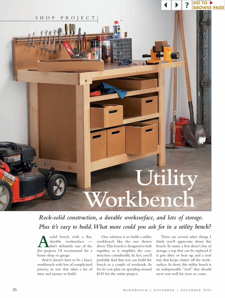
Rock-solid construction, a durable worksurface, and lots of storage.
Plus it’s easy to build.What more could you ask for in a utility bench?
Asolid bench with a flat,durable worksurface —that’s definitely one of the
first projects I’d recommend for ahome shop or garage.
And it doesn’t have to be a fancyworkbench with lots of complicatedjoinery, or one that takes a lot oftime and money to build.
One solution is to build a utilityworkbench like the one shownabove.This bench is designed to bolttogether, so it simplifies the con-struction considerably. In fact, you’llprobably find that you can build thebench in a couple of weekends. Asfor its cost, plan on spending around$150 for the entire project.
There are several other things Ithink you’ll appreciate about thisbench.To name a few, there’s lots ofstorage, a top that can be replaced ifit gets dirty or beat up, and a tooltray that keeps clutter off the work-surface. In short, this utility bench isan indispensable “tool” that shouldserve you well for years to come.
UtilityWorkbench
26 W O R K B E N C H ■■ N O V E M B E R | D E C E M B E R 2 0 0 1
S H O P P R O J E C T
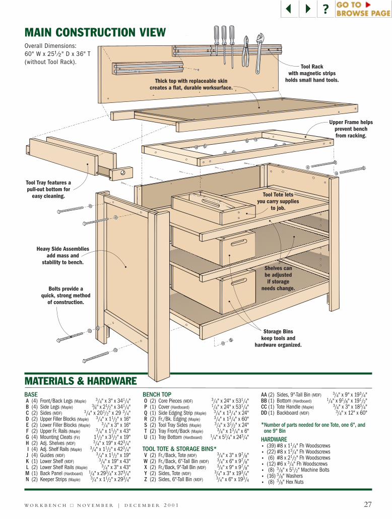
Tool Rackwith magnetic strips
holds small hand tools.
Upper Frame helpsprevent benchfrom racking.
Heavy Side Assembliesadd mass and
stability to bench.
Tool Tray features apull-out bottom for
easy cleaning.
Bolts provide aquick, strong method
of construction.
Thick top with replaceable skincreates a flat, durable worksurface.
Storage Binskeep tools and
hardware organized.
Shelves canbe adjustedif storage
needs change.
Tool Tote letsyou carry supplies
to job.
BASEA (4) Front/Back Legs (Maple) 3/4" x 3" x 341/4"B (4) Side Legs (Maple) 3/4" x 21/2" x 341/4"C (2) Sides (MDF) 3/4" x 201/2" x 29 3/4"D (2) Upper Filler Blocks (Maple) 3/4" x 11/2" x 16"E (2) Lower Filler Blocks (Maple) 3/4" x 3" x 16"F (2) Upper Fr. Rails (Maple) 3/4" x 11/2" x 43"G (4) Mounting Cleats (Fir) 11/2" x 31/2" x 19"H (2) Adj. Shelves (MDF) 3/4" x 19" x 423/4"I (4) Adj. Shelf Rails (Maple) 3/4" x 11/2" x 423/4"J (4) Guides (MDF) 3/4" x 11/2" x 19"K (1) Lower Shelf (MDF) 3/4" x 19" x 43"L (2) Lower Shelf Rails (Maple) 3/4" x 3" x 43"M (1) Back Panel (Hardboard) 1/4" x 293/4" x 373/4"N (2) Keeper Strips (Maple) 3/4" x 11/2" x 293/4"
BENCH TOPO (2) Core Pieces (MDF) 3/4" x 24" x 531/4"P (1) Cover (Hardboard) 1/4" x 24" x 531/4"Q (1) Side Edging Strip (Maple) 3/4" x 13/4" x 24"R (2) Fr./Bk. Edging (Maple) 3/4" x 13/4" x 60"S (2) Tool Tray Sides (Maple) 3/4" x 31/2" x 24"T (2) Tray Front/Back (Maple) 3/4" x 13/4" x 6"U (1) Tray Bottom (Hardboard) 1/4" x 51/4" x 243/4"
TOOL TOTE & STORAGE BINS*V (2) Fr./Back, Tote (MDF) 3/4" x 3" x 97/8"W (2) Fr./Back, 6"-Tall Bin (MDF) 3/4" x 6" x 97/8"X (2) Fr./Back, 9"-Tall Bin (MDF) 3/4" x 9" x 97/8"Y (2) Sides, Tote (MDF) 3/4" x 3" x 193/4"Z (2) Sides, 6"-Tall Bin (MDF) 3/4" x 6" x 193/4
AA (2) Sides, 9"-Tall Bin (MDF) 3/4" x 9" x 193/4"BB (1) Bottom (Hardboard) 1/4" x 91/8" x 191/2"CC (1) Tote Handle (Maple) 3/4" x 3" x 183/4"DD (1) Backboard (MDF) 3/4" x 12" x 60"
*Number of parts needed for one Tote, one 6", andone 9" Bin
HARDWARE• (39) #8 x 11/4" Fh Woodscrews• (22) #8 x 13/4" Fh Woodscrews• (6) #8 x 21/2" Fh Woodscrews• (12) #6 x 3/4" Fh Woodscrews• (8) 3/8" x 51/2" Machine Bolts• (16) 3/8" Washers• (8) 3/8" Hex Nuts
27W O R K B E N C H ■■ N O V E M B E R | D E C E M B E R 2 0 0 1
MATERIALS & HARDWARE
MAIN CONSTRUCTION VIEWOverall Dimensions:60" W x 25! /2" D x 36" T (without Tool Rack).
28 W O R K B E N C H ■■ N O V E M B E R | D E C E M B E R 2 0 0 1
BackPanel
M Keeper StripN
Back Rail#8 x 1 " Fh Woodscrew!/4
Back Leg
!/4"
#/8"
Bolt Upper Frame flush withtop of Side Assembly.
LegSide
MountingCleat
G
ASSEMBLY DETAIL
BACK DETAIL
CL
2#/4"
CL
#8 x 1 " Fh Woodscrew!/4
DUpper Filler
Block
ELower Filler
Block
Bolt hole locations
A BackLeg Piece
BSide Leg
Piece
CSide
2#/4"
6!/2"
1!/2"
2#/4"
A Front Leg Piece
NOTE: Drill 3/8" holes for bolts after Filler Blocks are glued on.
NOTE: Drill 1/4"Shelf Pin holes.
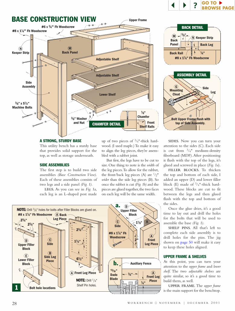
A STRONG, STURDY BASE This utility bench has a sturdy basethat provides solid support for thetop, as well as storage underneath.
SIDE ASSEMBLIESThe first step is to build two sideassemblies (Base Construction View).Each of these assemblies consists oftwo legs and a side panel (Fig. 1).
LEGS. As you can see in Fig. 1a,each leg is an L-shaped post made
up of two pieces of 3/4"-thick hard-wood. (I used maple.) To make it easyto align the leg pieces, they’re assem-bled with a rabbet joint.
But first, the legs have to be cut tosize. One thing to note is the width ofthe leg pieces.To allow for the rabbet,the front/back leg pieces (A) are 1/2"wider than the side leg pieces (B). Soonce the rabbet is cut (Fig. 1b) and thepieces are glued together, the two faceson each leg will be the same width.
SIDES. Now you can turn yourattention to the sides (C). Each sideis cut from 3/4" medium-densityfiberboard (MDF). After positioningit flush with the top of the legs, it’sglued and screwed in place (Fig. 1a).
FILLER BLOCKS. To thickenthe top and bottom of each side, Iadded an upper (D) and lower fillerblock (E) made of 3/4"-thick hard-wood. These blocks are cut to fitbetween the legs and then gluedflush with the top and bottom ofthe sides.
Once the glue dries, it’s a goodtime to lay out and drill the holesfor the bolts that will be used toassemble the base (Fig. 1).
SHELF PINS. All that’s left tocomplete each side assembly is todrill holes for the pins. The jigshown on page 50 will make it easyto keep these holes aligned.
UPPER FRAME & SHELVESAt this point, you can turn yourattention to the upper frame and lowershelf. The two adjustable shelves arequite similar, so it’s a good time tobuild them, as well.
UPPER FRAME. The upper frameis the main support for the benchtop.
SideAssembly
Upper Frame
Adjustable Shelf
Lower Shelf
NKeeper Strip
#8 x 1 Fh Woodscrew!/4"
#/8" Washerand Nut
#6 x Fh Woodscrew#/4"
#/8 !/2" x 5 "Machine Bolts
MBack Panel
Adjustable Shelf
CSide
A
B
DUpper Filler
Block
#8 x 1 " FhWoodscrew
!/4
FrontLeg Piece
1!/8"
2"
a.
Auxiliary Fence
!#/16"DadoBlade
#/4"
!/4"
Front LegPiece
A
b.
1
!/8"Chamfer
FrontShelf Rails
CHAMFER DETAIL
BASE CONSTRUCTION VIEW
FUpper Frame Rail
HAdjustable Shelf
#8 x 1 " Fh Woodscrews#/4
#8 x 2 "Fh Woodscrew
!/2
#8 x 1 "Fh Woodscrews
!/4
GMounting Cleat
GMounting Cleat
KLower Shelf
J Guide
J Guide
LLower Shelf Rail
IAdjustable Shelf Rail
29W O R K B E N C H ■■ N O V E M B E R | D E C E M B E R 2 0 0 1
UPPER FRAMEASSEMBLY
ADJUSTABLESHELFASSEMBLY(MAKE 2)
LOWER SHELFASSEMBLY
Lower ShelfAssembly
MountingCleat
Upper Frame
4!/2"
Lower FillerBlock
Side Assembly
#/8" Spade Bit
Lower ShelfSide
Lower Filler Block
Mounting Cleata.
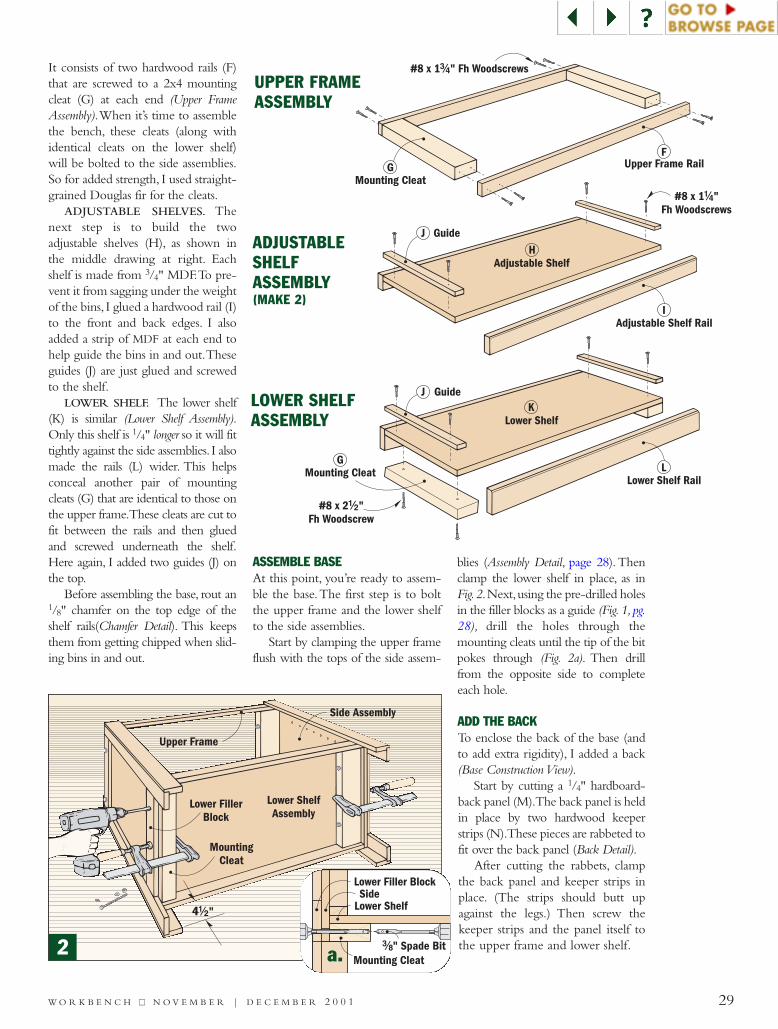
It consists of two hardwood rails (F)that are screwed to a 2x4 mountingcleat (G) at each end (Upper FrameAssembly).When it’s time to assemblethe bench, these cleats (along withidentical cleats on the lower shelf)will be bolted to the side assemblies.So for added strength, I used straight-grained Douglas fir for the cleats.
ADJUSTABLE SHELVES. Thenext step is to build the twoadjustable shelves (H), as shown inthe middle drawing at right. Eachshelf is made from 3/4" MDF.To pre-vent it from sagging under the weightof the bins, I glued a hardwood rail (I)to the front and back edges. I alsoadded a strip of MDF at each end tohelp guide the bins in and out.Theseguides (J) are just glued and screwedto the shelf.
LOWER SHELF. The lower shelf(K) is similar (Lower Shelf Assembly).Only this shelf is 1/4" longer so it will fittightly against the side assemblies. I alsomade the rails (L) wider. This helpsconceal another pair of mountingcleats (G) that are identical to those onthe upper frame.These cleats are cut tofit between the rails and then gluedand screwed underneath the shelf.Here again, I added two guides (J) onthe top.
Before assembling the base, rout an1/8" chamfer on the top edge of theshelf rails(Chamfer Detail). This keepsthem from getting chipped when slid-ing bins in and out.
ASSEMBLE BASEAt this point, you’re ready to assem-ble the base.The first step is to boltthe upper frame and the lower shelfto the side assemblies.
Start by clamping the upper frameflush with the tops of the side assem-
blies (Assembly Detail, page 28).Thenclamp the lower shelf in place, as inFig.2.Next,using the pre-drilled holesin the filler blocks as a guide (Fig.1,pg.28), drill the holes through themounting cleats until the tip of the bitpokes through (Fig. 2a). Then drillfrom the opposite side to completeeach hole.
ADD THE BACKTo enclose the back of the base (andto add extra rigidity), I added a back(Base Construction View).
Start by cutting a 1/4" hardboard-back panel (M).The back panel is heldin place by two hardwood keeperstrips (N).These pieces are rabbeted tofit over the back panel (Back Detail).
After cutting the rabbets, clampthe back panel and keeper strips inplace. (The strips should butt upagainst the legs.) Then screw thekeeper strips and the panel itself tothe upper frame and lower shelf.2
30
{{ A shallow tool tray mounted to the end of the bench holdssmall hand tools and keeps the worksurface free of clutter.
{{ To make it easy to clean the tool tray, just pull out thebottom and sweep dust and dirt into a trash can.
Q Side Edging Strip
R Front Edging Strip
#8 x 1 "Fh Woodscrew
#/4
OCore Pieces
Glue
CoverP
Tool TrayAssembly
#8 x 1 " Fh Woodscrew#/4
MountingCleat
Mounting Cleat
BENCH TOP ASSEMBLY
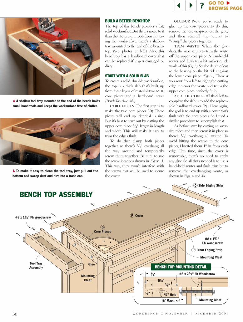
BUILD A BETTER BENCHTOPThe top of this bench provides a flat,solid worksurface.But there’s more to itthan that.To prevent tools from clutter-ing the worksurface, there’s a shallowtray mounted to the end of the bench-top. (See photos at left.) Also, thisbenchtop has a hardboard cover thatcan be replaced if it gets damaged ordirty.
START WITH A SOLID SLABTo create a solid, durable worksurface,the top is a thick slab that’s built upfrom three layers of material: two MDFcore pieces and a hardboard cover(Bench Top Assembly).
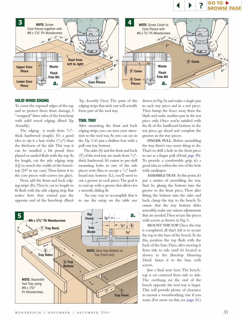
CORE PIECES.The first step is tomake the two core pieces (O).Thesepieces will end up identical in size.But it’s best to start out by cutting theupper core piece 1/2" larger in lengthand width. This will make it easy totrim the edges flush.
To do that, clamp both piecestogether so there’s 1/4" overhang allthe way around and temporarilyscrew them together. Be sure to usethe screw locations shown in Figure 3.This way, they won’t interfere withthe screws that will be used to securethe cover.
GLUE-UP. Now you’re ready toglue up the core pieces. To do this,remove the screws, spread on the glue,and then reinstall the screws to“clamp” the pieces together.
TRIM WASTE. When the gluedries, the next step is to trim the wasteoff the upper core piece.A hand-heldrouter and flush trim bit makes quickwork of this (Fig.3).Set the depth of cutso the bearing on the bit rides againstthe lower core piece (Fig. 3a).Then asyou rout from left to right, the cuttingedge removes the waste and trims theupper core piece perfectly flush.
ADD THE COVER.All that’s left tocomplete the slab is to add the replace-able hardboard cover (P). Here again,the goal is to end up with a cover that’sflush with the core pieces. So I used asimilar procedure to accomplish that.
As before, start by cutting an over-size piece, and then screw it in place sothere’s 1/4" overhang all around. Toavoid hitting the screws in the corepieces, I located them 1" in from eachedge. This time, since the cover isremoveable, there’s no need to applyany glue. So all that’s needed is to use ahand-held router and flush trim bit toremove the overhanging waste, asshown in Figs. 4 and 4a.
5!/4"
#8 x 2 " Fh Woodscrew!/2
CL
!/8" Gap
#/8"
#/8"
Mounting Cleat
CL!/2" #/4" Hole
BENCH TOP MOUNTING DETAIL
W O R K B E N C H ■■ N O V E M B E R | D E C E M B E R 2 0 0 1
31
Tray Sides
#8 x 1 " Fh Woodscrews#/4
S
Tray FrontT
Tray BackT
TrayBottomU
NOTE: AssembleTool Tray using#8 x 1 "Fh Woodscrews.
#/4
NOTE: Glue Tray Bottom toTray Front .only
!/4"
#/8"
#/8"
SawBlade
RipFence
S
1"
1"
1"
NOTE: Screw Cover toCore Pieces with
#6 x " Fh Woodscrews#/4
CoverPWaste
FlushTrim Bit
P Cover
CorePiecesO
a.
a.
Rout fromleft to right
NOTE: ScrewCore Pieces together with#8 x 1 " Fh Woodscrews!/4
OCore Pieces
CL
4" 4"
4"
4"Waste
FlushTrim Bit
Upper CorePiece
Lower CorePiece a.
SOLID WOOD EDGINGTo cover the exposed edges of the topand to protect them from damage, I“wrapped”three sides of the benchtopwith solid wood edging (Bench TopAssembly).
The edging is made from 3/4"-thick hardwood (maple). It’s a goodidea to rip it a hair wider (1/32") thanthe thickness of the slab. This way, itcan be installed a bit proud thenplaned or sanded flush with the top.Asfor length, cut the side edging strip(Q) to match the width of the bench-top (24" in my case).Then fasten it tothe core pieces with screws (no glue).
Next, add the front and back edg-ing strips (R).They’re cut to length tofit flush with the side edging strip.Butnotice how they extend past theopposite end of the benchtop (Bench
Top Assembly View). The parts of theedging strips that stick out will actuallyform part of the tool tray.
TOOL TRAYAfter mounting the front and backedging strips, you can turn your atten-tion to the tool tray.As you can see inthe Fig. 5, it’s just a shallow box with apull-out tray bottom.
The sides (S) and the front and back(T) of the tool tray are made from 3/4"-thick hardwood. It’s easiest to pre-drillmounting holes in one of the sidepieces now.Also, to accept a 1/4" hard-board tray bottom (U), you’ll need tocut a groove in each piece.The goal isto end up with a groove that allows fora smooth, sliding fit.
An easy way to accomplish that isto use the setup on the table saw
shown in Fig.5a and make a single passin each tray piece and in a test piece.Then bump the fence away from theblade and make another pass in the testpiece only. Once you’re satisfied withthe fit of the hardboard bottom in thetest piece, go ahead and complete thegrooves in the tray pieces.
FINGER PULL. Before assemblingthe tray, there’s one more thing to do.That’s to drill a hole in the front pieceto use as a finger pull (Detail, page 30).To provide a comfortable grip, it’s agood idea to soften the rim of the holewith sandpaper.
ASSEMBLE TRAY.At this point, it’sjust a matter of assembling the tray.Start by gluing the bottom into thegroove in the front piece. Then afterfitting the bottom into the sides andback, clamp the tray to the bench.Toensure that the tray bottom slidessmoothly,make any minor adjustmentsthat are needed.Then secure the pieceswith screws as shown in Fig. 5.
MOUNT THE TOP. Once the trayis completed, all that’s left is to securethe top to the base of the bench.To dothis, position the top flush with theback of the base.Then, after moving itfrom side to side until it’s located asshown in the Benchtop MountingDetail, fasten it to the base withscrews.
Just a final note here.The bench-top is not centered from side to side.The overhang on the end of thebench opposite the tool tray is larger.This will provide plenty of clearanceto mount a woodworking vise if youwant. (For more on this, see page 33.)
5
3 4
W O R K B E N C H ■■ N O V E M B E R | D E C E M B E R 2 0 0 1
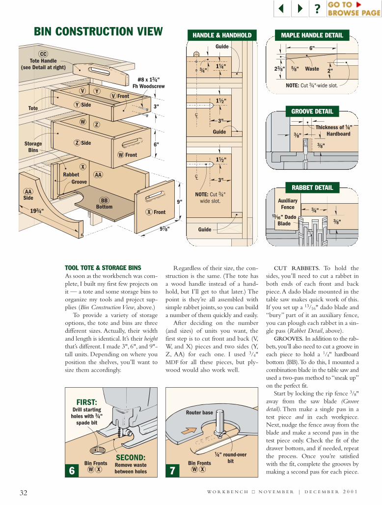
9"
9 "&/8
3"
19#/4"
RabbetGroove
6"
SideAA
AA
BottomBB
Tote Handle(see Detail at right)
CC
V
W
X
FrontX
FrontW
Side
#8 x 1 "Fh Woodscrew
#/4
Z
Z
FrontV
Y
Y
Side
StorageBins
Tote
32 W O R K B E N C H ■■ N O V E M B E R | D E C E M B E R 2 0 0 1
BIN CONSTRUCTION VIEW
2 "#/8 2"Waste
NOTE: Cut "-wide slot.#/4
%/8"
6"
CL
CL
Guide
NOTE: Cut "wide slot.
#/4
1!/2"
3"
1!/4"
Guide
Guide
#/4"
1!/2"
3"
#/8"
#/8"
Thickness of "Hardboard
!/4
AuxiliaryFence
#/8"
#/4"!#/16" Dado
Blade
GROOVE DETAIL
RABBET DETAIL
MAPLE HANDLE DETAILHANDLE & HANDHOLD
TOOL TOTE & STORAGE BINSAs soon as the workbench was com-plete, I built my first few projects onit — a tote and some storage bins toorganize my tools and project sup-plies (Bin Construction View, above.)
To provide a variety of storageoptions, the tote and bins are threedifferent sizes. Actually, their widthand length is identical. It’s their heightthat’s different. I made 3", 6", and 9"-tall units. Depending on where youposition the shelves, you’ll want tosize them accordingly.
Regardless of their size, the con-struction is the same. (The tote hasa wood handle instead of a hand-hold, but I’ll get to that later.) Thepoint is they’re all assembled withsimple rabbet joints, so you can builda number of them quickly and easily.
After deciding on the number(and sizes) of units you want, thefirst step is to cut front and back (V,W, and X) pieces and two sides (Y,Z, AA) for each one. I used 3/4"MDF for all these pieces, but ply-wood would also work well.
CUT RABBETS. To hold thesides, you’ll need to cut a rabbet inboth ends of each front and backpiece.A dado blade mounted in thetable saw makes quick work of this.If you set up a 13/16" dado blade and“bury” part of it an auxiliary fence,you can plough each rabbet in a sin-gle pass (Rabbet Detail, above).
GROOVES. In addition to the rab-bets, you’ll also need to cut a groove ineach piece to hold a 1/4" hardboardbottom (BB).To do this, I mounted acombination blade in the table saw andused a two-pass method to “sneak up”on the perfect fit.
Start by locking the rip fence 3/8"away from the saw blade (Groovedetail). Then make a single pass in atest piece and in each workpiece.Next, nudge the fence away from theblade and make a second pass in thetest piece only. Check the fit of thedrawer bottom, and if needed, repeatthe process. Once you’re satisfiedwith the fit, complete the grooves bymaking a second pass for each piece.
Router base
!/4" round-overbit
W XBin Fronts
FIRST:Drill starting
holes with "spade bit
#/4
SECOND:Remove wastebetween holesW X
Bin Fronts
6 7
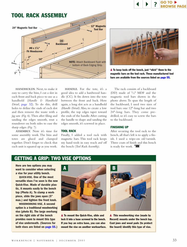
1"
2"
CL
14"
14"
24" Magnetic Tool Bar
NOTE: Attach Backboard flush withbottom of Back Edging Strip.
12" MagneticTool Bar
#8 x 1 "Fh Woodscrew
!/4
BackboardDD
33W O R K B E N C H ■■ N O V E M B E R | D E C E M B E R 2 0 0 1
HANDHOLDS. Next, to make iteasy to carry the bins, I cut a slot ineach front and back piece to use as ahandhold (Handle & HandholdDetail, page 32). To do this, drillholes to define the ends of each slotand then remove the waste with ajig saw (Fig. 6). Then after filing andsanding the edges smooth, rout aroundover on both sides to ease thesharp edges (Fig. 7).
ASSEMBLY. Now it’s time forsome assembly work. The bins andtotes are glued and clampedtogether. Don’t forget to check thateach unit is squared up as you work.
HANDLE. For the tote, it’s agood idea to add a hardwood han-dle (CC). It fits down into the totebetween the front and back. Hereagain, a long slot acts as a handhold(Handle Detail).Also, to create a lowprofile, the top edges taper towardthe ends of the handle.After cuttingthe handle to shape and sanding theedges smooth, it’s screwed in place.
TOOL RACKFinally, I added a tool rack withmagnetic bars. This tool rack keepsmy hand tools in easy reach and offthe bench (Tool Rack Assembly).
The rack consists of a backboard(DD) made of 3/4" MDF and themagnetic tool bars shown in thephoto above. To span the length ofthe backboard, I used two sizes oftool bars: one 12"-long bar and two24"-long bars. They come pre-drilled, so it’s easy to screw the barsto the backboard.
FINISHING UPAfter securing the tool rack to thebench, all that’s left is to apply a fin-ish. I used a wipe-on oil/varnish.Three coats of finish and this benchis ready for work.
TOOL RACK ASSEMBLY
GETTING A GRIP: TWO VISE OPTIONSHere are two options you maywant to consider when selectinga vise for your utility bench.
QUICK-VISE. One of the mostversatile vises I’ve seen is the newQuick-Vise. Made of durable plas-tic, it mounts easily to the benchtop (Photo A). To clamp a work-piece, slide the jaws open (5"max.) and tighten the front knob.
WOODWORKING VISE. A secondoption is a traditional woodworkingvise (photo B). The large overhangon the right side of the benchprovides room to mount this typeof vise underneath. (Sources forboth vises are listed on page 55.)
{{ To keep tools off the bench, just “stick” them to the magnetic bars on the tool rack. These manufactured toolbars are available from the sources listed on page 55.
{{ To mount the Quick-Vise, slide andlock it into a base screwed to the bench.If you buy an extra base, you can alsomount the vise on another worksurface.
{{ This woodworking vise (made byRecord) mounts under the bench top.Cast jaws and wood pads (to protectthe board) identify this type of vise.
A B
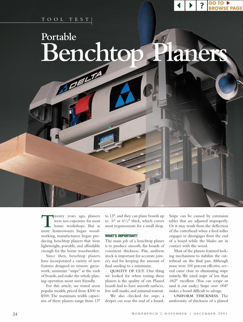
34 W O R K B E N C H ■■ N O V E M B E R | D E C E M B E R 2 0 0 1
T O O L T E S T
Twenty years ago, planerswere too expensive for mosthome workshops. But as
more homeowners began wood-working, manufacturers began pro-ducing benchtop planers that werelightweight, portable, and affordableenough for the home woodworker.
Since then, benchtop planershave incorporated a variety of newfeatures designed to remove guess-work, minimize “snipe” at the endsof boards, and make the whole plan-ing operation more user friendly.
For this article, we tested sevenpopular models, priced from $300 to$500. The maximum width capaci-ties of these planers range from 12"
to 13", and they can plane boards upto 6" or 61/2" thick, which coversmost requirements for a small shop.
WHAT’S IMPORTANT?The main job of a benchtop planeris to produce smooth, flat boards ofconsistent thickness. Flat, uniformstock is important for accurate join-ery and for keeping the amount offinal sanding to a minimum.
QUALITY OF CUT. One thingwe looked for when testing theseplaners is the quality of cut. Planedboards had to have smooth surfaces,few mill marks, and minimal tearout.
We also checked for snipe, adeeper cut near the end of a board.
Snipe can be caused by extensiontables that are adjusted improperly.Or it may result from the deflectionof the cutterhead when a feed rollerengages or disengages from the endof a board while the blades are incontact with the wood.
Most of the planers featured lock-ing mechanisms to stabilize the cut-terhead on the final pass. Althoughnone were 100 percent effective, sev-eral came close to eliminating snipeentirely. We rated snipe of less than.002" excellent. (You can scrape orsand it out easily.) Snipe over .004"makes a board difficult to salvage.
UNIFORM THICKNESS. Theuniformity of thickness of a planed
Benchtop Planers Portable
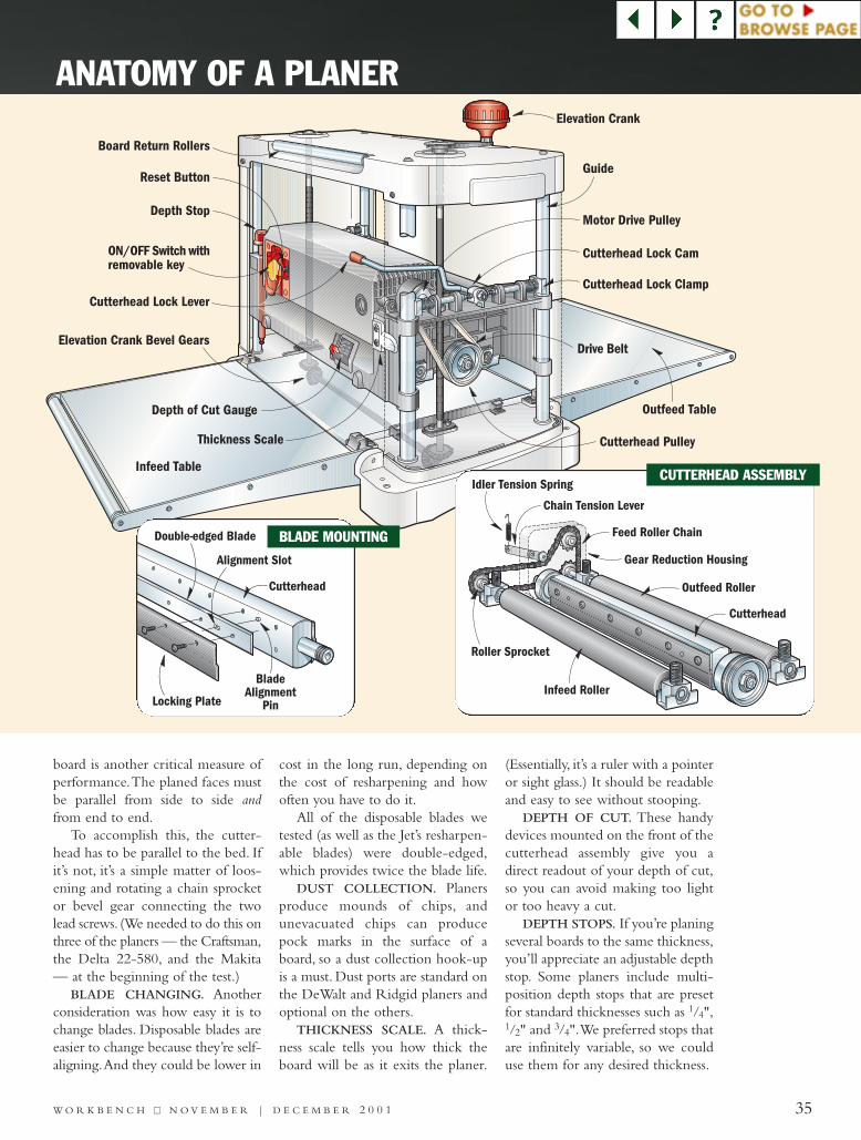
35W O R K B E N C H ■■ N O V E M B E R | D E C E M B E R 2 0 0 1
board is another critical measure ofperformance.The planed faces mustbe parallel from side to side andfrom end to end.
To accomplish this, the cutter-head has to be parallel to the bed. Ifit’s not, it’s a simple matter of loos-ening and rotating a chain sprocketor bevel gear connecting the twolead screws. (We needed to do this onthree of the planers — the Craftsman,the Delta 22-580, and the Makita— at the beginning of the test.)
BLADE CHANGING. Anotherconsideration was how easy it is tochange blades. Disposable blades areeasier to change because they’re self-aligning.And they could be lower in
cost in the long run, depending onthe cost of resharpening and howoften you have to do it.
All of the disposable blades wetested (as well as the Jet’s resharpen-able blades) were double-edged,which provides twice the blade life.
DUST COLLECTION. Planersproduce mounds of chips, andunevacuated chips can producepock marks in the surface of aboard, so a dust collection hook-upis a must. Dust ports are standard onthe DeWalt and Ridgid planers andoptional on the others.
THICKNESS SCALE. A thick-ness scale tells you how thick theboard will be as it exits the planer.
(Essentially, it’s a ruler with a pointeror sight glass.) It should be readableand easy to see without stooping.
DEPTH OF CUT. These handydevices mounted on the front of thecutterhead assembly give you adirect readout of your depth of cut,so you can avoid making too lightor too heavy a cut.
DEPTH STOPS. If you’re planingseveral boards to the same thickness,you’ll appreciate an adjustable depthstop. Some planers include multi-position depth stops that are presetfor standard thicknesses such as 1/4",1/2" and 3/4".We preferred stops thatare infinitely variable, so we coulduse them for any desired thickness.
Depth StopMotor Drive Pulley
ON/OFF Switch withremovable key
Reset Button
Elevation Crank Bevel Gears
Infeed Table
Board Return Rollers
Elevation Crank
Cutterhead Lock Cam
Cutterhead Lock Clamp
Cutterhead PulleyThickness Scale
Cutterhead Lock Lever
Outfeed Table
Drive Belt
Depth of Cut Gauge
Guide
Idler Tension Spring
Chain Tension Lever
Gear Reduction Housing
Outfeed Roller
Cutterhead
Infeed Roller
Roller Sprocket
Feed Roller Chain
Cutterhead
Locking Plate
Double-edged Blade
BladeAlignment
Pin
Alignment Slot
ANATOMY OF A PLANER
BLADE MOUNTING
CUTTERHEAD ASSEMBLY
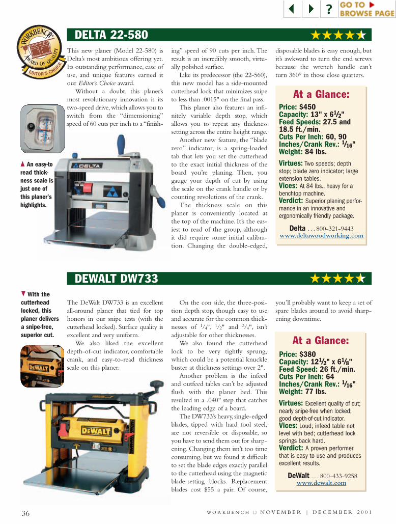
This new planer (Model 22-580) isDelta’s most ambitious offering yet.Its outstanding performance, ease ofuse, and unique features earned itour Editor’s Choice award.
Without a doubt, this planer’smost revolutionary innovation is itstwo-speed drive, which allows you toswitch from the “dimensioning”speed of 60 cuts per inch to a “finish-
ing” speed of 90 cuts per inch. Theresult is an incredibly smooth, virtu-ally polished surface.
Like its predecessor (the 22-560),this new model has a side-mountedcutterhead lock that minimizes snipeto less than .0015" on the final pass.
This planer also features an infi-nitely variable depth stop, whichallows you to repeat any thicknesssetting across the entire height range.
Another new feature, the “bladezero” indicator, is a spring-loadedtab that lets you set the cutterheadto the exact initial thickness of theboard you’re planing. Then, yougauge your depth of cut by usingthe scale on the crank handle or bycounting revolutions of the crank.
The thickness scale on thisplaner is conveniently located atthe top of the machine. It’s the eas-iest to read of the group, althoughit did require some initial calibra-tion. Changing the double-edged,
disposable blades is easy enough, butit’s awkward to turn the end screwsbecause the wrench handle can’tturn 360° in those close quarters.
36 W O R K B E N C H ■■ N O V E M B E R | D E C E M B E R 2 0 0 1
DELTA 22-580
The DeWalt DW733 is an excellentall-around planer that tied for tophonors in our snipe tests (with thecutterhead locked). Surface quality isexcellent and very uniform.
We also liked the excellentdepth-of-cut indicator, comfortablecrank, and easy-to-read thicknessscale on this planer.
On the con side, the three-posi-tion depth stop, though easy to useand accurate for the common thick-nesses of 1/4", 1/2" and 3/4", isn’tadjustable for other thicknesses.
We also found the cutterheadlock to be very tightly sprung,which could be a potential knucklebuster at thickness settings over 2".
Another problem is the infeedand outfeed tables can’t be adjustedflush with the planer bed. Thisresulted in a .040" step that catchesthe leading edge of a board.
The DW733’s heavy, single-edgedblades, tipped with hard tool steel,are not reversible or disposable, soyou have to send them out for sharp-ening. Changing them isn’t too timeconsuming, but we found it difficultto set the blade edges exactly parallelto the cutterhead using the magneticblade-setting blocks. Replacementblades cost $55 a pair. Of course,
you’ll probably want to keep a set ofspare blades around to avoid sharp-ening downtime.
At a Glance:Price: $450Capacity: 13" x 61/2"Feed Speeds: 27.5 and18.5 ft./min.Cuts Per Inch: 60, 90Inches/Crank Rev.: 1/16"Weight: 84 lbs.Virtues: Two speeds; depthstop; blade zero indicator; largeextension tables.Vices: At 84 lbs., heavy for abenchtop machine.Verdict: Superior planing perfor-mance in an innovative andergonomically friendly package.
Delta . . . 800-321-9443www.deltawoodworking.com
DEWALT DW733
At a Glance:Price: $380Capacity: 121/2" x 61/8"Feed Speed: 26 ft./min.Cuts Per Inch: 64Inches/Crank Rev.: 1/16"Weight: 77 lbs.Virtues: Excellent quality of cut;nearly snipe-free when locked;good depth-of-cut indicator.Vices: Loud; infeed table notlevel with bed; cutterhead locksprings back hard.Verdict: A proven performerthat is easy to use and producesexcellent results.
DeWalt . . . 800-433-9258www.dewalt.com
AWARD OF QUALIT
Y
EDITOR’S CHOICE
WO
RKBENCH ®
{ An easy-toread thick-ness scale isjust one ofthis planer’shighlights.
} With thecutterheadlocked, thisplaner deliversa snipe-free,superior cut.
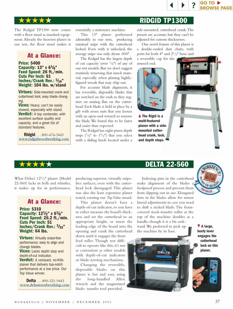
What Delta’s 121/2" planer (Model22-560) lacks in bells and whistles,it makes up for in performance,
producing superior, virtually snipe-free surfaces, even with the cutter-head lock disengaged. This planerwas also the least expensive planertested, earning our Top Value award.
This planer doesn’t have adepth-of-cut indicator, so you haveto either measure the board’s thick-ness and set the cutterhead to anappropriate height, or insert theleading edge of the board into theopening and crank the cutterheaddown until it engages the frontfeed roller. Though not diffi-cult to operate like this, it’s notas convenient as other modelswith depth-of-cut indicatorsor blade-zeroing mechanisms.
Changing the reversible,disposable blades on thisplaner is fast and easy, usingthe long-handled Allenwrench and the magnetizedblade- transfer tool provided.
Indexing pins in the cutterheadmake alignment of the blades afoolproof process and prevent themfrom slipping out in use. Elongatedslots in the blades allow for minorlateral adjustments in case you needto shift a nicked blade. The foam-covered stock-transfer roller at thetop of the machine doubles as ahandle, though it is a bit awk-ward.We preferred to pick upthe machine by its base.
37W O R K B E N C H ■■ N O V E M B E R | D E C E M B E R 2 0 0 1
DELTA 22-560
At a Glance:Price: $400Capacity: 13" x 61/8"Feed Speed: 26 ft./min.Cuts Per Inch: 61Inches/Crank Rev.: 1/16"Weight: 104 lbs. w/standVirtues: Side-mounted crank andcutterhead lock; easy blade chang-ing.Vices: Heavy; can’t be easilystowed, especially with stand.Verdict: A top contender, withexcellent surface quality andcapacity, and a great list ofstandard features.
Ridgid . . . 800-474-3443www.ridgidwoodworking.com
At a Glance:Price: $310Capacity: 121/2" x 61/8"Feed Speed: 26.2 ft./min.Cuts Per Inch: 51Inches/Crank Rev.: 3/32"Weight: 64 lbs.Virtues: Virtually snipe-freeperformance; easy to align andchange blades.Vices: Lacks depth stop anddepth-of-cut indicator.Verdict: A compact, no-frillsplaner that delivers top-notchperformance at a low price. OurTop Value winner.
Delta . . . 800-321-9443www.deltawoodworking.com
RIDGID TP1300 The Ridgid TP1300 now comeswith a floor stand as standard equip-ment.Already the heaviest planer inour test, the floor stand makes it
essentially a stationary machine.This 13" planer performed
admirably in our tests, producingminimal snipe with the cutterheadlocked. Even with it unlocked, theaverage snipe was only about .004".
The Ridgid has the largest depthof cut capacity (over 1/8") of any ofour test models. But we don’t suggestroutinely removing that much mate-rial, especially when planing highly-figured woods that may chip out.
For accurate blade alignment, ithas reversible, disposable blades thatare notched on the ends so they reg-ister on mating flats on the cutter-head. Each blade is held in place by agib with seven nuts that you loosenwith an open-end wrench to removethe blade.We found this to be fasterand easier than expected.
The Ridgid has eight preset depthstops (1/8" to 13/4") that you selectwith a sliding knob located under a
side-mounted, cutterhead crank.Thepresets are accurate, but they can’t beadjusted for custom thicknesses.
One novel feature of this planer isa double-ended dust chute, withports for both 4" and 21/2" hose anda reversible cap for theunused end.
AW
ARD OF QUALITY
®
WORKBENCH
®
RE
TOP VALUE
{ The Rigid is amulti-featuredplaner with a side-mounted cutter-head crank, lock,and depth stops.
} A large,beefy leverengages the
cutterheadlock on thisplaner.
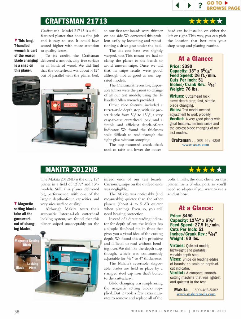
LockingPlateBlade
38 W O R K B E N C H ■■ N O V E M B E R | D E C E M B E R 2 0 0 1
CRAFTSMAN 21713
MAKITA 2012NB
} This long,T-handledwrench is partof the reasonblade changingis a snap onthis planer.
} Magneticsetting blockstake all theguessworkout of chang-ing blades.
At a Glance:Price: $390Capacity: 13" x 65/16"Feed Speed: 26 ft./min.Cuts Per Inch: 51Inches/Crank Rev.: 1/16"Weight: 76 lbs.Virtues: Cutterhead lock;turret depth stop; fast, simpleblade changing.Vices: Test model needed adjustment to work properly.Verdict: A very good planer withgreat features, minimal snipe andthe easiest blade changing of ourtest models.
Craftsman . . . 800-349-4358www.sears.com
At a Glance:Price: $490Capacity: 121/2" x 61/8"Feed Speed: 27.9 ft./min.Cuts Per Inch: 51Inches/Crank Rev.: 5/64"Weight: 60 lbs.Virtues: Quietest model;lightweight and portable;variable depth stop.Vices: Snipe on leading edgesof boards; no scale on depth-of-cut indicator.Verdict: A compact, smooth-cutting machine that was lightestand quietest in the test.
Makita . . . 800-462-5482www.makitatools.com
Craftsman’s Model 21713 is a full-featured planer that does a fine joband is easy to use. It could havescored higher with more attentionto quality issues.
To its credit, the Craftsmandelivered a smooth, chip-free surfacein all kinds of wood. We did findthat the cutterhead was about .012"out of parallel with the planer bed,
so our first test boards were thinneron one side.We corrected this prob-lem easily by loosening and reposi-tioning a drive gear under the bed.
The die-cast base was slightlywarped, too. This meant we had toclamp the planer to the bench toavoid uneven snipe. Once we didthat, its snipe results were good,although not as good as our top-rated models.
The Craftsman’s reversible, dispos-able knives were the easiest to changeof all our test models, using the T-handled Allen wrench provided.
Other nice features included aturret-style depth stop with six pre-set depths from 1/8" to 11/4", a veryeasy-to-use cutterhead lock, and asimple and efficient depth-of-cutindicator. We found the thicknessscale difficult to read through thesight glass without stooping.
The top-mounted crank that’sused to raise and lower the cutter-
head can be installed on either theleft or right.This way, you can pickthe location that best suits yourshop setup and planing routine.
The Makita 2012NB is the only 12"planer in a field of 121/2" and 13"-models. Still, this planer deliveredbig performance, with one of thelargest depth-of-cut capacities andvery nice surface quality.
Although Makita touts theirautomatic Interna-Lok cutterheadlocking system, we found that thisplaner sniped unacceptably on the
infeed ends of our test boards.Curiously, snipe on the outfeed endswas negligible.
The Makita was noticeably (andmeasurably) quieter than the otherplaners (about 4 to 5 dB quieterwhen planing). Even so, you stillneed hearing protection.
Instead of a direct reading indica-tor for depth of cut, the Makita hasa simple, flat-head pin in front thatgives you a visual idea of the cuttingdepth.We found this a bit primitiveand difficult to read without bend-ing over.We did like the depth stop,though, which was continuouslyadjustable for 1/8 " to 4" thicknesses.
The Makita’s reversible, dispos-able blades are held in place by astamped steel cap iron that’s boltedto the cutterhead.
Blade changing was simple usingthe magnetic setting blocks sup-plied. But it took a few extra min-utes to remove and replace all of the
bolts. Finally, the dust chute on thisplaner has a 3"-dia. port, so you’llneed an adapter if you want to use a4" dust hose.
Magnetic SettingBlock
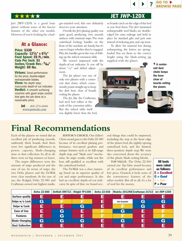
E
EE E E
E E EE Not AvailableG
GE E
E EEG
G G G G G
GG G
G GFF
F
FF F F
F
E E E E E E
E E E E E E E
Each of the planers we tested did anexcellent job of producing smooth,uniformly thick boards. And therewere few significant differences inpower, capacity, blade-changingtime or dust collection. So all in all,there were no big winners or losers.
The major differences were theamount of snipe produced and theease of use. In terms of snipe, thetwo Delta planers and the DeWaltwere clear standouts. As for ease ofuse, the Ridgid, Delta 22-580 andCraftsman earned our highest marks.
EDITOR’S CHOICE. Our Editor’sChoice award goes to the Delta 22-580because of its excellent planing per-formance, two-speed gearbox andunique features such as its full-rangedepth stop, and “blade zero” mecha-nism. Its snipe results, while not thebest, still qualified as excellent withthe cutterhead locked.
The DeWalt was a close runner-up, based on its superior quality ofcut and snipe performance. It alsohad an excellent depth-of-cut indi-cator. In spite of that, we found sev-
eral things that could be improved,including the step at the front edgeof the planer bed, the tightly-sprungcutterhead lock, and the limited,three-position depth stop. We werealso concerned about the accuracyof the plastic blade-setting blocks.
TOP VALUE. The Delta 22-560earned our Top Value award becauseof its excellent performance andlow price. Granted, it lacks some ofthe convenience features of theother models. But all in all, it’s a lotof tool for the money.
Final Recommendations
39W O R K B E N C H ■■ N O V E M B E R | D E C E M B E R 2 0 0 1
JET JWP-12DX Jet’s JWP-12DX is a good basicplaner without some of the fancierfeatures of the other test models.However, if you’re looking for a bud-
get-minded tool, this one definitelydeserves your attention.
Overall, the Jet’s planing quality wasquite good, producing very smoothsurfaces with minimal snipe.The twincutterhead locking handles on thefront of the machine are handy, but it’seasy to forget whether they’re engaged.Plus,the handles get in the way of fold-ing up the infeed extension table.
We weren’t impressed with thedepth-of-cut indicator. It was off byabout 1/16" and defied adjust-ment.
The Jet planer was one ofonly two planers with a center-exit dust chute, which conve-niently points straight up to keepthe dust hose clear of boardsexiting the planer.
The Jet, like the Craftsman,had steel bed rollers at theends of the extension tables.But the infeed table itselfwas slightly lower than the bed,
so boards catch on the edge of the bedas you feed them.The Jet’s laminatedresharpenable steel blades are double-edged for extra mileage and held inplace by standard gibs and jack nutsinstead of indexing pins and cap irons.
To allow for material lost duringresharpening, the knives are spring-loaded. You set them to the correctheight using the blade-setting jigsupplied with the planer.
Delta 22-580
Surface quality
Snipe w/o Lock
Snipe w/Lock
Ease of Use
Features
Blade Changing
Dust Collection
DeWalt DW733 Ridgid TP1300 Delta 22-560 Makita 2012NB Craftsman 21713 Jet JWP-12DX
} A center-exit dustchute keepsthe hoseclear ofboards exitingthe planer.
At a Glance:Price: $330Capacity: 121/2" x 61/2"Feed Speed: 26 ft./min.Cuts Per Inch: 51Inches/Crank Rev.: 5/64"Weight: 69 lbs.Virtues: Good performancefor the price; double-edged,resharpenable blades.Vices: No depth stop;inaccurate depth-of cut indicator.Verdict: A smooth surfacingmachine with good snipe controlthat gets the job done at areasonable price.
Jet . . . 800-274-6848www.jettools.com
All tools were ratedas follows:
E = ExcellentG = GoodF = FairP = Poor
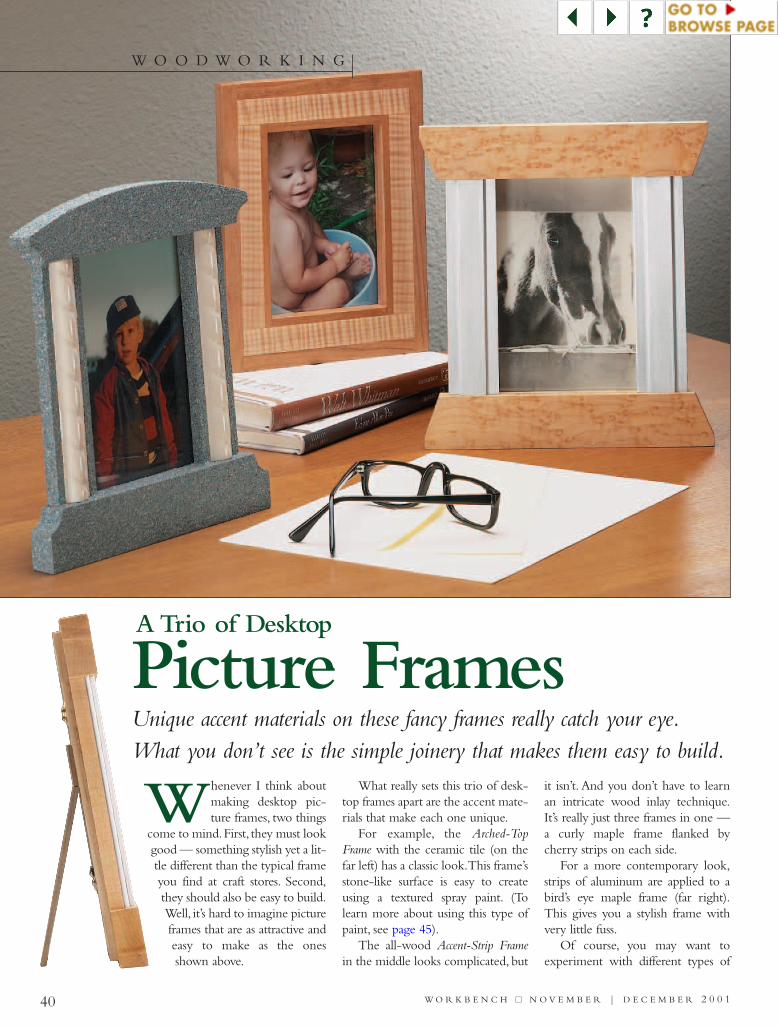
40 W O R K B E N C H ■■ N O V E M B E R | D E C E M B E R 2 0 0 1
W O O D W O R K I N G
Unique accent materials on these fancy frames really catch your eye.What you don’t see is the simple joinery that makes them easy to build.
Picture Frames
Whenever I think aboutmaking desktop pic-ture frames, two things
come to mind.First, they must lookgood — something stylish yet a lit-tle different than the typical frameyou find at craft stores. Second,they should also be easy to build.Well, it’s hard to imagine pictureframes that are as attractive andeasy to make as the onesshown above.
What really sets this trio of desk-top frames apart are the accent mate-rials that make each one unique.
For example, the Arched-TopFrame with the ceramic tile (on thefar left) has a classic look.This frame’sstone-like surface is easy to createusing a textured spray paint. (Tolearn more about using this type ofpaint, see page 45).
The all-wood Accent-Strip Framein the middle looks complicated, but
it isn’t. And you don’t have to learnan intricate wood inlay technique.It’s really just three frames in one —a curly maple frame flanked bycherry strips on each side.
For a more contemporary look,strips of aluminum are applied to abird’s eye maple frame (far right).This gives you a stylish frame withvery little fuss.
Of course, you may want toexperiment with different types of
A Trio of Desktop
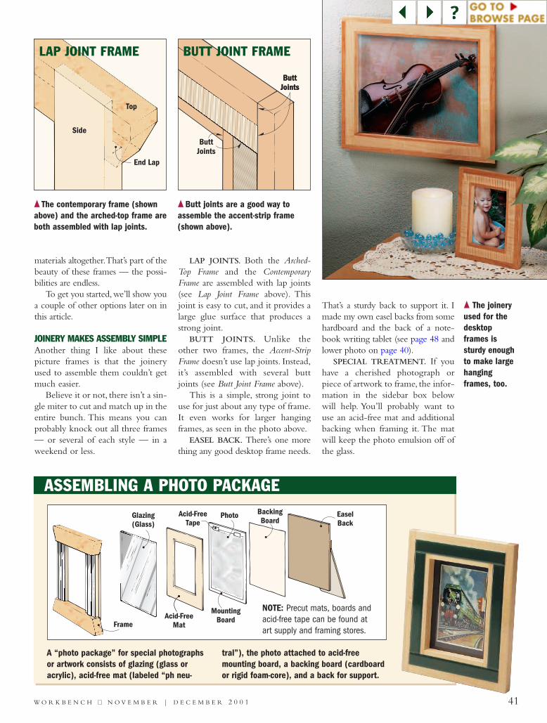
41W O R K B E N C H ■■ N O V E M B E R | D E C E M B E R 2 0 0 1
materials altogether.That’s part of thebeauty of these frames — the possi-bilities are endless.
To get you started, we’ll show youa couple of other options later on inthis article.
JOINERY MAKES ASSEMBLY SIMPLEAnother thing I like about thesepicture frames is that the joineryused to assemble them couldn’t getmuch easier.
Believe it or not, there isn’t a sin-gle miter to cut and match up in theentire bunch. This means you canprobably knock out all three frames— or several of each style — in aweekend or less.
LAP JOINTS. Both the Arched-Top Frame and the ContemporaryFrame are assembled with lap joints(see Lap Joint Frame above). Thisjoint is easy to cut, and it provides alarge glue surface that produces astrong joint.
BUTT JOINTS. Unlike theother two frames, the Accent-StripFrame doesn’t use lap joints. Instead,it’s assembled with several buttjoints (see Butt Joint Frame above).
This is a simple, strong joint touse for just about any type of frame.It even works for larger hangingframes, as seen in the photo above.
EASEL BACK. There’s one morething any good desktop frame needs.
That’s a sturdy back to support it. Imade my own easel backs from somehardboard and the back of a note-book writing tablet (see page 48 andlower photo on page 40).
SPECIAL TREATMENT. If youhave a cherished photograph orpiece of artwork to frame, the infor-mation in the sidebar box belowwill help. You’ll probably want touse an acid-free mat and additionalbacking when framing it. The matwill keep the photo emulsion off ofthe glass.
LAP JOINT FRAME BUTT JOINT FRAME
{ The joineryused for thedesktopframes issturdy enoughto make largehangingframes, too.
{ The contemporary frame (shownabove) and the arched-top frame areboth assembled with lap joints.
{ Butt joints are a good way toassemble the accent-strip frame(shown above).
ASSEMBLING A PHOTO PACKAGE
A “photo package” for special photographsor artwork consists of glazing (glass oracrylic), acid-free mat (labeled “ph neu-
tral”), the photo attached to acid-freemounting board, a backing board (cardboardor rigid foam-core), and a back for support.
Frame
Glazing(Glass)
Acid-FreeMat
Acid-FreeTape
MountingBoard
BackingBoard
Photo EaselBack
NOTE: Precut mats, boards andacid-free tape can be found atart supply and framing stores.
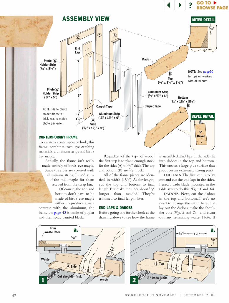
PhotoHolder Strip( " x 5")#/4
PhotoHolder Strip( " x 8 ")#/4 !/2
EndLap
Side( x 1 x 9 )#/8" !/2" "
Bottom( x 1 x 8 )#/4" !/2" !/2"
Top( x 1 x 8 )#/4" !/2" !/2"
Dado
Aluminum Strip( " x " x 6")!/8 #/4
Aluminum Strip( " x 1 " x 6")!/8 !/2
Carpet TapeCarpet Tape
A
A
B
B
6"
1 "!/2
C
C
CC
42 W O R K B E N C H ■■ N O V E M B E R | D E C E M B E R 2 0 0 1
CONTEMPORARY FRAMETo create a contemporary look, thisframe combines two eye-catchingmaterials: aluminum strips and bird’seye maple.
Actually, the frame isn’t reallymade entirely of bird’s-eye maple.
Since the sides are covered withaluminum strips, I used run-
of-the-mill maple for themrescued from the scrap bin.
Of course, the top andbottom don’t have to bemade of bird’s-eye mapleeither.To produce a nice
contrast with the aluminum, theframe on page 43 is made of poplarand then spray painted black.
Regardless of the type of wood,the first step is to plane enough stockfor the sides (A) to 3/8" thick.The topand bottom (B) are 3/4" thick.
All of the frame pieces are iden-tical in width (11/2"). As for length,cut the top and bottom to finallength.But make the sides about 1/2"longer than needed. They’retrimmed to final length later.
END LAPS & DADOESBefore going any further, look at thedrawing above to see how the frame
is assembled. End laps in the sides fitinto dadoes in the top and bottom.This creates a large glue surface thatproduces an extremely strong joint.
END LAPS.The first step is to layout and cut the end laps in the sides.I used a dado blade mounted in thetable saw to do this (Figs. 1 and 1a).
DADOES. Next, cut the dadoesin the top and bottom.There’s noneed to change the setup here. Justlay out the dadoes, make the shoul-der cuts (Figs. 2 and 2a), and cleanout any remaining waste. Note: If
!/2" Dado Blade
TopB
ASSEMBLY VIEW
21
NOTE: See page50for tips on workingwith aluminum.
NOTE: Plane photoholder strips tothickness to matchphoto package.
a. a.
%/16"
!/2"
MITER DETAIL
BEVEL DETAIL
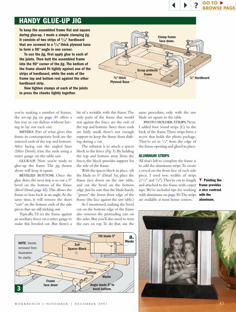
you’re making a number of frames,the set-up jig on page 49 offers afast way to cut dadoes without hav-ing to lay out each one.
MITERS. Part of what gives thisframe its contemporary look are themitered ends of the top and bottom.After laying out the angled lines(Miter Detail), trim the ends using amiter gauge on the table saw.
GLUE-UP. Now you’re ready toglue-up the frame. The jig shownabove will keep it square.
BEVELED BOTTOM. Once theglue dries, the next step is to cut a 5°bevel on the bottom of the frame(Bevel Detail, page 42).This allows theframe to lean back at an angle.At thesame time, it will remove the short“ears” on the bottom ends of the sidepieces that are still sticking out.
Typically, I’d set the frame againstan auxiliary fence on a miter gauge tomake this beveled cut. But there’s a
bit of a wrinkle with this frame.Theonly parts of the frame that wouldrest against the fence are the ends ofthe top and bottom. Since these endsare fairly small, there’s not enoughsupport to keep the frame from shift-ing during a cut.
The solution is to attach a spacerblock to the fence (Fig.3).By holdingthe top and bottom away from thefence, the block provides support forthe side of the frame.
With the spacer block in place, tiltthe blade to 5° (Detail 3a), place theframe face down on the saw table,and cut the bevel on the bottomedge. Just be sure that the blade barely“grazes” the lower front edge of theframe (the face against the saw table.)
As I mentioned, making the bevelcut on the bottom edge of the framealso removes the protruding ears onthe sides. But you’ll also need to trimthe ears on top. To do that, use the
same procedure, only with the sawblade set square to the table.
PHOTO HOLDER STRIPS.Next,I added four wood strips (C) to theback of the frame.These strips form arecess that holds the photo package.They’re set in 1/4" from the edge ofthe frame opening and glued in place.
ALUMINUM STRIPSAll that’s left to complete the frame isto add the aluminum strips.To createa reveal on the front face of each sidepiece, I used two widths of strips(11/2" and 3/4").They’re cut to lengthand attached to the frame with carpettape.We’ve included tips for workingwith aluminum on page 50.The stripsare available at most home centers.
43W O R K B E N C H ■■ N O V E M B E R | D E C E M B E R 2 0 0 1
}} Painting theframe providesa nice contrastwith the aluminum.
2x4Spacer Block
Waste
Top
Bottom
Frameface down Angle blade 5 to
bevel bottom.º
Clamp frameface down.
#/4"-thickPlywood Base
!/4" Hardboard
Scrap protectsframe
Tilt blade 5ºWaste
HANDY GLUE-UP JIG To keep the assembled frame flat and squareduring glue-up, I made a simple clamping jig.It consists of two strips of 1/4" hardboardthat are screwed to a 3/4"-thick plywood baseto form a 90° angle in one corner.
To use the jig, first apply glue to each ofthe joints. Then butt the assembled frameinto the 90° corner of the jig. The bottom ofthe frame should fit tightly against one of thestrips of hardboard, while the ends of theframe top and bottom rest against the otherhardboard strip.
Now tighten clamps at each of the jointsto press the cheeks tightly together.
a.
3
NOTE: Hands removed fromillustration for clarity.

44 W O R K B E N C H ■■ N O V E M B E R | D E C E M B E R 2 0 0 1
ARCHED-TOP FRAMEThis frame uses pieces of rope tile andstone-textured paint to create a clas-
sic look. It’s assembled just likethe Contemporary Frame. But
what’s different is that eachside also has a shallowgroove that holds a piece ofceramic tile.
PREPARE THE TILES.Chances are you’ll need to
clean up any rough glazing on theedges and bottom of the tile piecesbefore you can use them.This is easy
to do by simply knocking off therough spots with some sandpaper.
SIZE THE PIECES. Once thetiles are ready, it’s time to beginwork on the frame pieces. I startedby planing my stock to thickness.Then I ripped the sides (A), top andbottom (B) to width and cut themto length (see dimensions above).
MAKING THE GROOVESWith the pieces sized, the next stepis to center a groove in each sidepiece.This is a cut-to-fit process.
First raise a 1/2" dado blade tomake a 3/16"-deep cut (Fig. 4a).Thenusing a test piece (same width as thesides), I positioned the fence to estab-lish the shoulder of the groove andmade the first pass (Fig. 4). Now flipthe test piece end-for-end and makeanother pass (Figs. 5 and 5a).
You’ll probably have to sneak upon the groove width. If it’s too nar-row, nudge the fence away from theblade and make two more passes.Once the tile fits flush (Tile Detail),cut the grooves in the side pieces.
ASSEMBLY VIEWNOTE: Rope tile is available at homecenters for about $2 per 6" piece.
a. a.
SideCross Section
Tile
#/16"
54
BEVEL DETAIL
NOTE: Plane photo holderstrips to thickness to matchphoto package.
TILE DETAIL
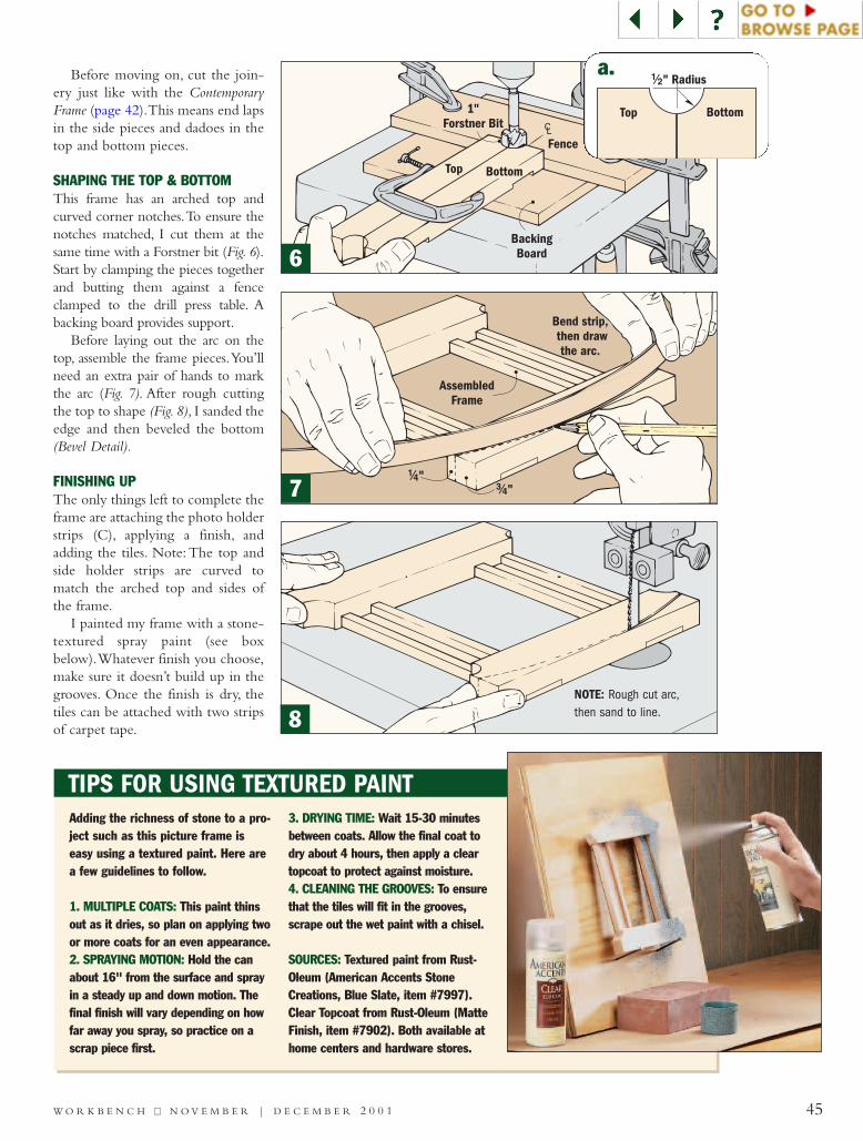
TIPS FOR USING TEXTURED PAINT
45W O R K B E N C H ■■ N O V E M B E R | D E C E M B E R 2 0 0 1
Before moving on, cut the join-ery just like with the ContemporaryFrame (page 42).This means end lapsin the side pieces and dadoes in thetop and bottom pieces.
SHAPING THE TOP & BOTTOMThis frame has an arched top andcurved corner notches.To ensure thenotches matched, I cut them at thesame time with a Forstner bit (Fig. 6).Start by clamping the pieces togetherand butting them against a fenceclamped to the drill press table. Abacking board provides support.
Before laying out the arc on thetop, assemble the frame pieces.You’llneed an extra pair of hands to markthe arc (Fig. 7). After rough cuttingthe top to shape (Fig. 8), I sanded theedge and then beveled the bottom(Bevel Detail).
FINISHING UPThe only things left to complete theframe are attaching the photo holderstrips (C), applying a finish, andadding the tiles. Note: The top andside holder strips are curved tomatch the arched top and sides ofthe frame.
I painted my frame with a stone-textured spray paint (see boxbelow).Whatever finish you choose,make sure it doesn’t build up in thegrooves. Once the finish is dry, thetiles can be attached with two stripsof carpet tape.
Adding the richness of stone to a pro-ject such as this picture frame iseasy using a textured paint. Here area few guidelines to follow.
1. MULTIPLE COATS: This paint thinsout as it dries, so plan on applying twoor more coats for an even appearance. 2. SPRAYING MOTION: Hold the canabout 16" from the surface and sprayin a steady up and down motion. Thefinal finish will vary depending on howfar away you spray, so practice on ascrap piece first.
3. DRYING TIME: Wait 15-30 minutesbetween coats. Allow the final coat todry about 4 hours, then apply a cleartopcoat to protect against moisture.4. CLEANING THE GROOVES: To ensurethat the tiles will fit in the grooves,scrape out the wet paint with a chisel.
SOURCES: Textured paint from Rust-Oleum (American Accents StoneCreations, Blue Slate, item #7997).Clear Topcoat from Rust-Oleum (MatteFinish, item #7902). Both available athome centers and hardware stores.
6
7
8NOTE: Rough cut arc,then sand to line.
a.
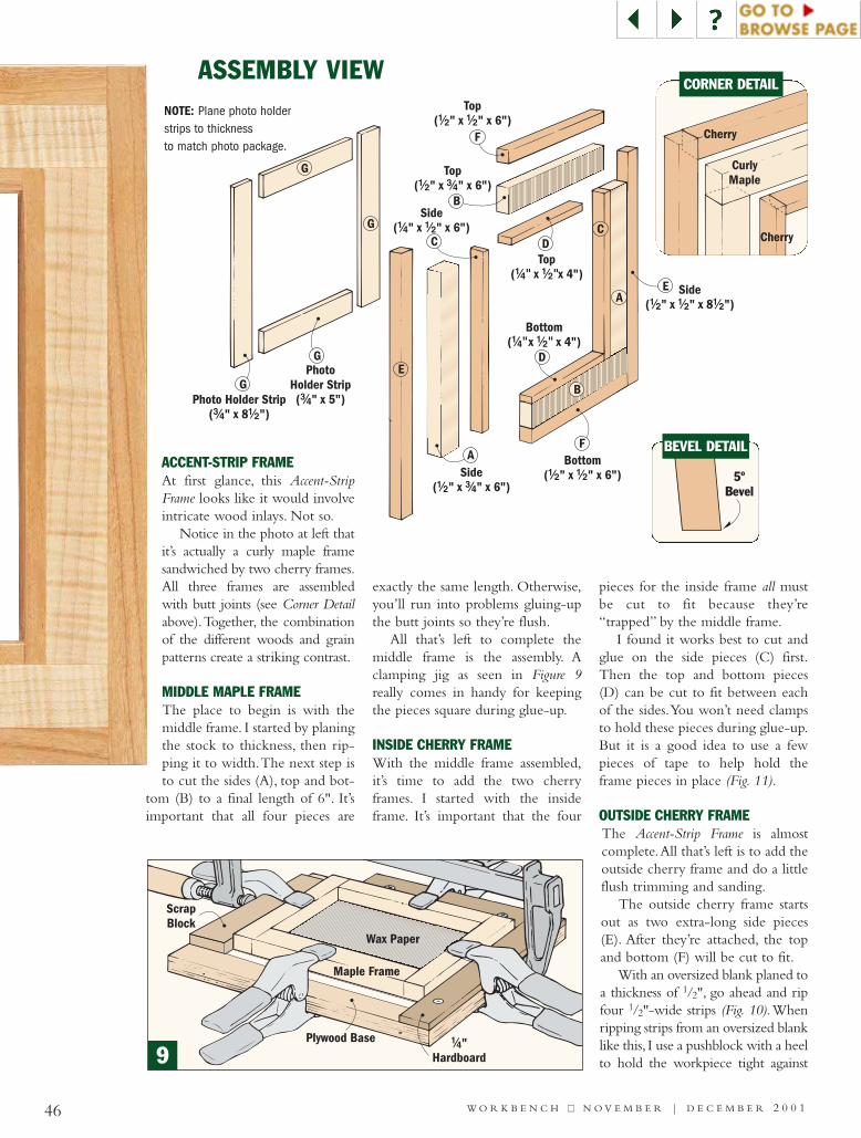
46 W O R K B E N C H ■■ N O V E M B E R | D E C E M B E R 2 0 0 1
Side( " x " x 6")!/2 #/4
Side( " x " x 6")!/4 !/2
Bottom( x x 4")!/4" !/2"
Top( x x 4")!/4" !/2"
Bottom( " x " x 6")!/2 !/2
Top( " x " x 6")!/2 !/2
Side( " x " x 8 ")!/2 !/2 !/2
A
PhotoHolder Strip( " x 5")#/4Photo Holder Strip
( " x 8 ")#/4 !/2
Top( " x " x 6")!/2 #/4
B
A
B
D
D
F
C
F
E
E
C
G
G
G
G
ACCENT-STRIP FRAMEAt first glance, this Accent-StripFrame looks like it would involveintricate wood inlays. Not so.
Notice in the photo at left thatit’s actually a curly maple framesandwiched by two cherry frames.All three frames are assembledwith butt joints (see Corner Detailabove).Together, the combinationof the different woods and grainpatterns create a striking contrast.
MIDDLE MAPLE FRAME The place to begin is with themiddle frame. I started by planingthe stock to thickness, then rip-ping it to width.The next step isto cut the sides (A), top and bot-
tom (B) to a final length of 6". It’simportant that all four pieces are
exactly the same length. Otherwise,you’ll run into problems gluing-upthe butt joints so they’re flush.
All that’s left to complete themiddle frame is the assembly. Aclamping jig as seen in Figure 9really comes in handy for keepingthe pieces square during glue-up.
INSIDE CHERRY FRAMEWith the middle frame assembled,it’s time to add the two cherryframes. I started with the insideframe. It’s important that the four
pieces for the inside frame all mustbe cut to fit because they’re“trapped” by the middle frame.
I found it works best to cut andglue on the side pieces (C) first.Then the top and bottom pieces(D) can be cut to fit between eachof the sides.You won’t need clampsto hold these pieces during glue-up.But it is a good idea to use a fewpieces of tape to help hold theframe pieces in place (Fig. 11).
OUTSIDE CHERRY FRAMEThe Accent-Strip Frame is almostcomplete.All that’s left is to add theoutside cherry frame and do a littleflush trimming and sanding.
The outside cherry frame startsout as two extra-long side pieces(E). After they’re attached, the topand bottom (F) will be cut to fit.
With an oversized blank planed toa thickness of 1/2", go ahead and ripfour 1/2"-wide strips (Fig. 10).Whenripping strips from an oversized blanklike this, I use a pushblock with a heelto hold the workpiece tight against
ASSEMBLY VIEW
9
CORNER DETAIL
BEVEL DETAIL
NOTE: Plane photo holderstrips to thickness to match photo package.
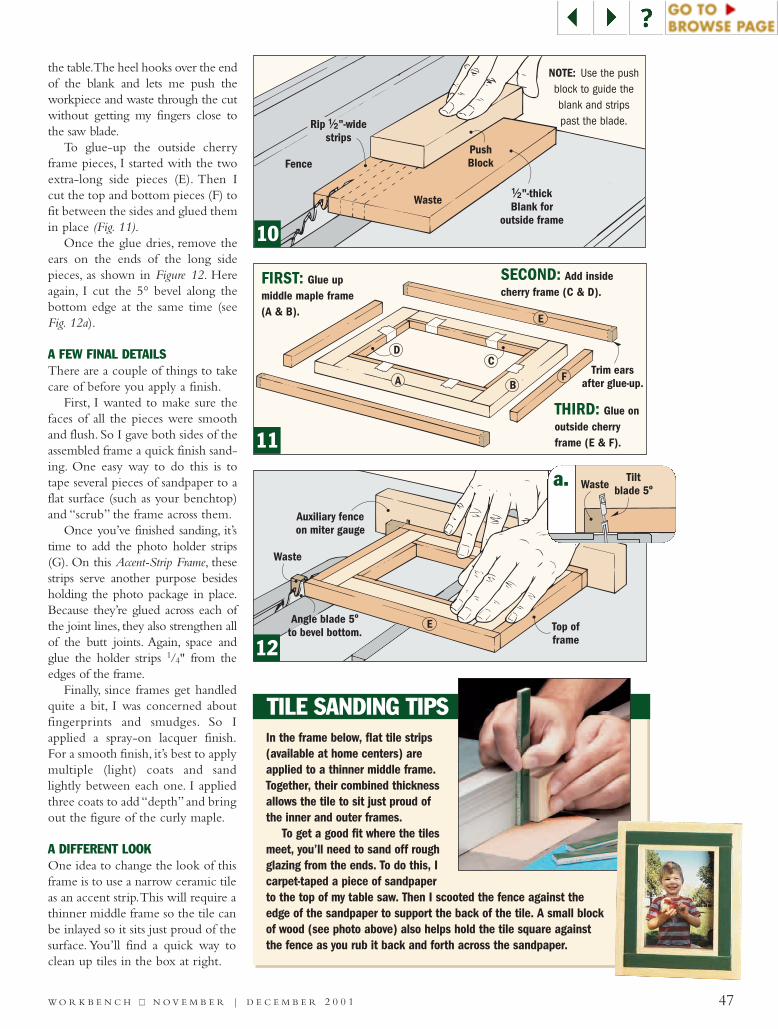
47W O R K B E N C H ■■ N O V E M B E R | D E C E M B E R 2 0 0 1
the table.The heel hooks over the endof the blank and lets me push theworkpiece and waste through the cutwithout getting my fingers close tothe saw blade.
To glue-up the outside cherryframe pieces, I started with the twoextra-long side pieces (E). Then Icut the top and bottom pieces (F) tofit between the sides and glued themin place (Fig. 11).
Once the glue dries, remove theears on the ends of the long sidepieces, as shown in Figure 12. Hereagain, I cut the 5° bevel along thebottom edge at the same time (seeFig. 12a).
A FEW FINAL DETAILSThere are a couple of things to takecare of before you apply a finish.
First, I wanted to make sure thefaces of all the pieces were smoothand flush. So I gave both sides of theassembled frame a quick finish sand-ing. One easy way to do this is totape several pieces of sandpaper to aflat surface (such as your benchtop)and “scrub” the frame across them.
Once you’ve finished sanding, it’stime to add the photo holder strips(G). On this Accent-Strip Frame, thesestrips serve another purpose besidesholding the photo package in place.Because they’re glued across each ofthe joint lines, they also strengthen allof the butt joints. Again, space andglue the holder strips 1/4" from theedges of the frame.
Finally, since frames get handledquite a bit, I was concerned aboutfingerprints and smudges. So Iapplied a spray-on lacquer finish.For a smooth finish, it’s best to applymultiple (light) coats and sandlightly between each one. I appliedthree coats to add “depth” and bringout the figure of the curly maple.
A DIFFERENT LOOKOne idea to change the look of thisframe is to use a narrow ceramic tileas an accent strip.This will require athinner middle frame so the tile canbe inlayed so it sits just proud of thesurface. You’ll find a quick way toclean up tiles in the box at right.
In the frame below, flat tile strips(available at home centers) areapplied to a thinner middle frame.Together, their combined thicknessallows the tile to sit just proud ofthe inner and outer frames.
To get a good fit where the tilesmeet, you’ll need to sand off roughglazing from the ends. To do this, Icarpet-taped a piece of sandpaperto the top of my table saw. Then I scooted the fence against theedge of the sandpaper to support the back of the tile. A small blockof wood (see photo above) also helps hold the tile square againstthe fence as you rub it back and forth across the sandpaper.
Rip "-widestrips!/2
Waste
PushBlockFence
!/2"-thickBlank for
outside frame
TILE SANDING TIPS
1212
1211
FIRST: Glue upmiddle maple frame(A & B).
SECOND: Add insidecherry frame (C & D).
THIRD: Glue onoutside cherryframe (E & F).
10
Tiltblade 5ºWastea.
NOTE: Use the pushblock to guide theblank and stripspast the blade.
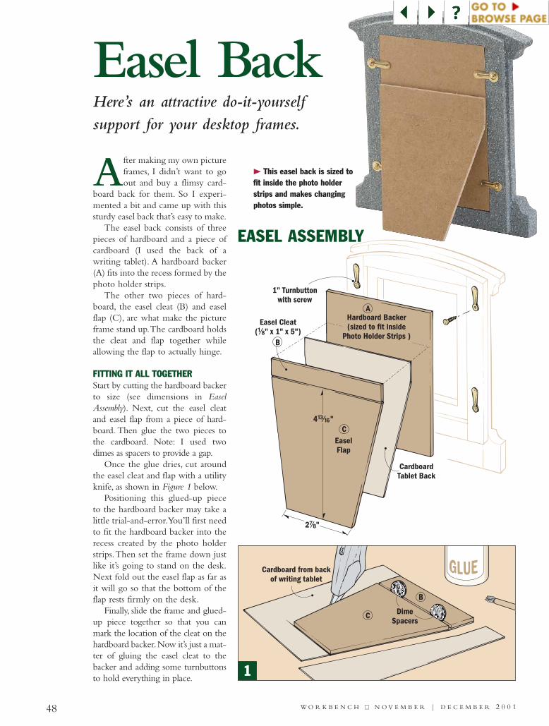
48 W O R K B E N C H ■■ N O V E M B E R | D E C E M B E R 2 0 0 1
EASEL ASSEMBLY
Easel Back
After making my own pictureframes, I didn’t want to goout and buy a flimsy card-
board back for them. So I experi-mented a bit and came up with thissturdy easel back that’s easy to make.
The easel back consists of threepieces of hardboard and a piece ofcardboard (I used the back of awriting tablet). A hardboard backer(A) fits into the recess formed by thephoto holder strips.
The other two pieces of hard-board, the easel cleat (B) and easelflap (C), are what make the pictureframe stand up.The cardboard holdsthe cleat and flap together whileallowing the flap to actually hinge.
FITTING IT ALL TOGETHERStart by cutting the hardboard backerto size (see dimensions in EaselAssembly). Next, cut the easel cleatand easel flap from a piece of hard-board. Then glue the two pieces tothe cardboard. Note: I used twodimes as spacers to provide a gap.
Once the glue dries, cut aroundthe easel cleat and flap with a utilityknife, as shown in Figure 1 below.
Positioning this glued-up pieceto the hardboard backer may take alittle trial-and-error.You’ll first needto fit the hardboard backer into therecess created by the photo holderstrips.Then set the frame down justlike it’s going to stand on the desk.Next fold out the easel flap as far asit will go so that the bottom of theflap rests firmly on the desk.
Finally, slide the frame and glued-up piece together so that you canmark the location of the cleat on thehardboard backer.Now it’s just a mat-ter of gluing the easel cleat to thebacker and adding some turnbuttonsto hold everything in place.
Here’s an attractive do-it-yourselfsupport for your desktop frames.
121
>> This easel back is sized tofit inside the photo holderstrips and makes changingphotos simple.
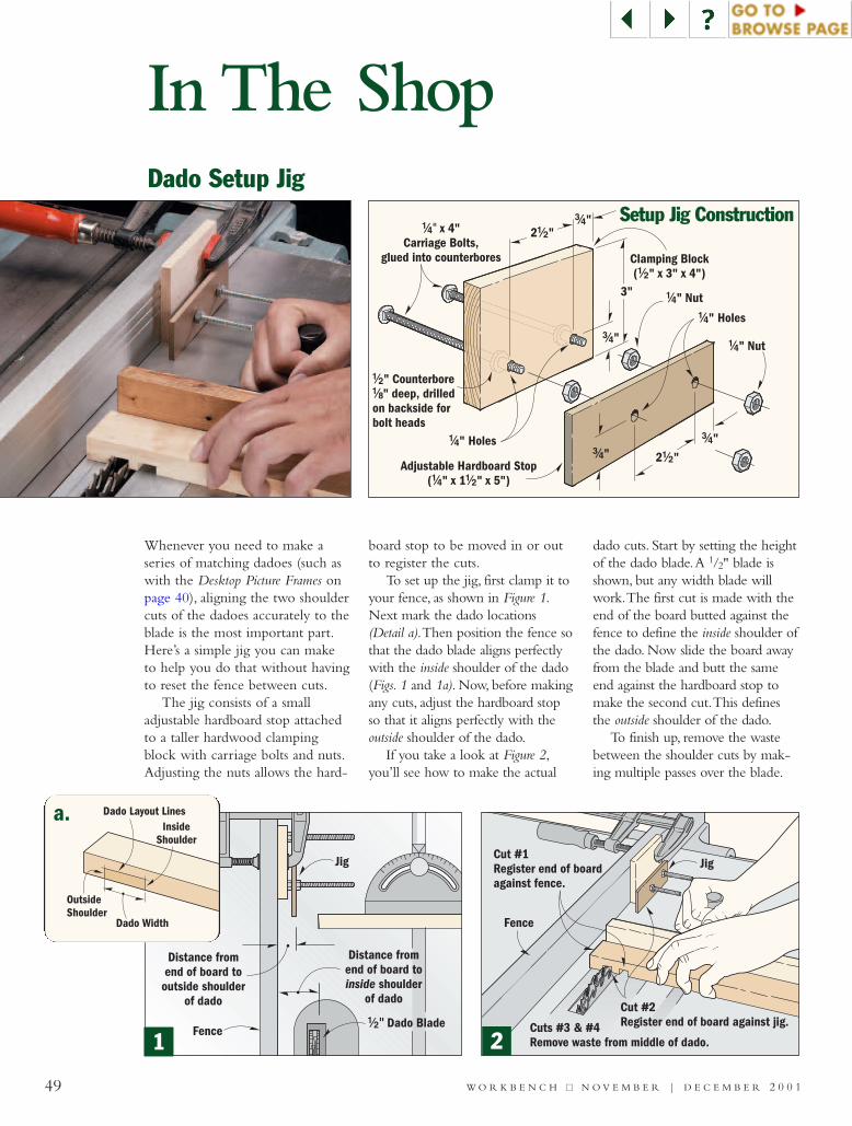
Whenever you need to make aseries of matching dadoes (such aswith the Desktop Picture Frames onpage 40), aligning the two shouldercuts of the dadoes accurately to theblade is the most important part.Here’s a simple jig you can maketo help you do that without havingto reset the fence between cuts.
The jig consists of a smalladjustable hardboard stop attachedto a taller hardwood clampingblock with carriage bolts and nuts.Adjusting the nuts allows the hard-
board stop to be moved in or outto register the cuts.
To set up the jig, first clamp it toyour fence, as shown in Figure 1.Next mark the dado locations(Detail a).Then position the fence sothat the dado blade aligns perfectlywith the inside shoulder of the dado(Figs. 1 and 1a). Now, before makingany cuts, adjust the hardboard stopso that it aligns perfectly with theoutside shoulder of the dado.
If you take a look at Figure 2,you’ll see how to make the actual
dado cuts. Start by setting the heightof the dado blade.A 1/2" blade isshown, but any width blade willwork.The first cut is made with theend of the board butted against thefence to define the inside shoulder ofthe dado. Now slide the board awayfrom the blade and butt the sameend against the hardboard stop tomake the second cut.This definesthe outside shoulder of the dado.
To finish up, remove the wastebetween the shoulder cuts by mak-ing multiple passes over the blade.
49 W O R K B E N C H ■■ N O V E M B E R | D E C E M B E R 2 0 0 1
In The ShopDado Setup Jig
Adjustable Hardboard Stop( " x 1 " x 5")!/4 !/2
Clamping Block( " x 3" x 4")!/2
3"
!/4" Holes
!/4" Nut
#/4"
#/4"2 "!/2
#/4"#/4"
2 "!/2
!/4" Holes
!/4" Nut
!/2
!/8
" Counterbore" deep, drilled
on backside forbolt heads
!/4" x 4"Carriage Bolts,
glued into counterbores
Cuts #3 & #4Remove waste from middle of dado.
Fence
Cut #1Register end of boardagainst fence.
Cut #2Register end of board against jig.
Jig
Distance fromend of board to
shoulderof dado
inside
Jig
Fence
Distance fromend of board tooutside shoulder
of dado
!/2" Dado Blade
Setup Jig Construction
Dado Layout Lines
Dado Width
OutsideShoulder
InsideShoulder
211
a.
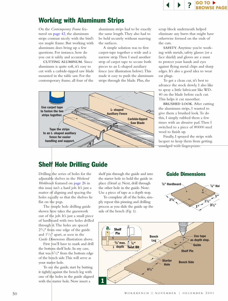
50 W O R K B E N C H ■■ N O V E M B E R | D E C E M B E R 2 0 0 1
Shelf Hole Drilling GuideDrilling the series of holes for theadjustable shelves in the WeekendWorkbench featured on page 26 inthis issue isn’t a hard job. It’s just amatter of aligning and spacing theholes equally so that the shelves lieflat on the pegs.
The simple hole drilling guideshown here takes the guessworkout of the job. It’s just a small pieceof hardboard with two holes drilledthrough it.The holes are spaced23/4" from one edge of the guideand 11/2" apart, as seen in theGuide Dimensions illustration above.
First you’ll have to mark and drillthe bottom shelf hole. In my case,that was 61/2" from the bottom edgeof the bench side.This will serve asyour starter hole.
To use the guide, start by buttingit tightly against the bench leg withone of the holes in the guide alignedwith the starter hole. Now insert a
shelf pin through the guide and intothe starter hole to hold the guide inplace (Detail a). Next, drill throughthe other hole in the guide. Note:Use a piece of tape as a depth stop.
To complete all of the holes, sim-ply repeat this pinning and drillingprocess as you slide the guide up theside of the bench (Fig. 1).
On the Contemporary Frame fea-tured on page 42, the aluminumstrips contrast nicely with the bird’seye maple frame. But working withaluminum does bring up a fewquestions. For instance, how doyou cut it safely and accurately.
CUTTING ALUMINUM. Sincealuminum is quite soft, it’s easy tocut with a carbide-tipped saw blademounted in the table saw. For thecontemporary frame, all four of the
aluminum strips had to be exactlythe same length.They also had tobe held securely without marringthe surfaces.
A simple solution was to firstcarpet-tape together a wide and anarrow strip.Then I used anotherstrip of carpet tape to secure bothpieces to an L-shaped auxiliaryfence (see illustration below).Thismade it easy to push the aluminumstrips through the blade. Plus, the
scrap block underneath helpedeliminate any burrs that might haveotherwise formed on the ends ofthe cuts.
SAFETY.Anytime you’re work-ing with metals, safety glasses (or aface shield) and gloves are a mustto protect your hands and eyesagainst flying metal chips and sharpedges. It’s also a good idea to wearear plugs.
To get a clean cut, it’s best toadvance the stock slowly. I also liketo spray a little lubricant like WD-40 on the blade before each cut.This helps it cut smoother.
BRUSHED LOOK. After cuttingthe aluminum strips, I wanted togive them a brushed look.To dothis, I simply rubbed them a fewtimes with an abrasive pad.Then Iswitched to a piece of #0000 steelwool to finish up.
Finally, I sprayed the strips withlacquer to keep them from gettingsmudged with fingerprints.
Working with Aluminum Strips
Guide Dimensions
1
#/8"max.depth
ShelfPin
!/4"Twist Bit
1
a.
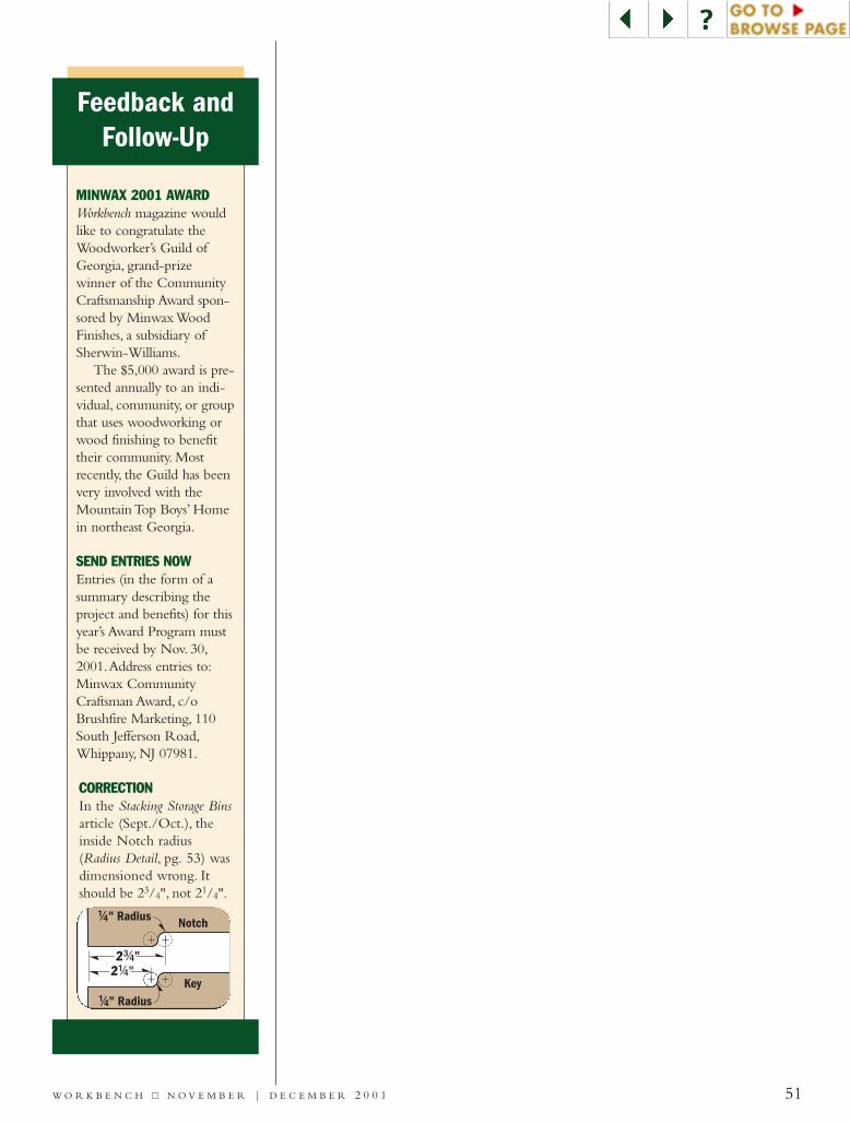
Feedback andFollow-Up
MINWAX 2001 AWARDWorkbench magazine wouldlike to congratulate theWoodworker’s Guild ofGeorgia, grand-prize winner of the CommunityCraftsmanship Award spon-sored by Minwax WoodFinishes, a subsidiary ofSherwin-Williams.
The $5,000 award is pre-sented annually to an indi-vidual, community, or groupthat uses woodworking orwood finishing to benefittheir community. Mostrecently, the Guild has beenvery involved with theMountain Top Boys’ Homein northeast Georgia.
SEND ENTRIES NOWEntries (in the form of asummary describing theproject and benefits) for thisyear’s Award Program mustbe received by Nov. 30,2001.Address entries to:Minwax CommunityCraftsman Award, c/oBrushfire Marketing, 110South Jefferson Road,Whippany, NJ 07981.
!/4" Radius
!/4" Radius Notch
Key
22
#/4"#/4"!/4"!/4"
CORRECTIONIn the Stacking Storage Binsarticle (Sept./Oct.), theinside Notch radius(Radius Detail, pg. 53) wasdimensioned wrong. Itshould be 23/4", not 21/4".
51W O R K B E N C H ■■ N O V E M B E R | D E C E M B E R 2 0 0 1
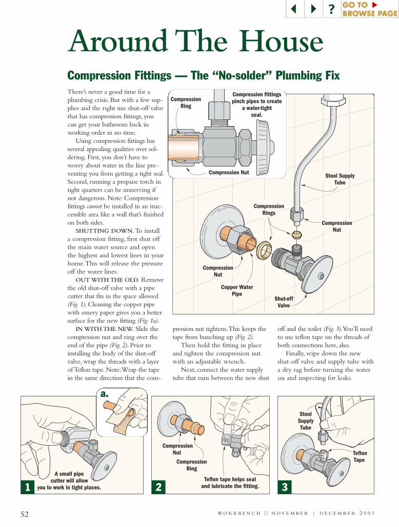
There’s never a good time for aplumbing crisis. But with a few sup-plies and the right size shut-off valvethat has compression fittings, youcan get your bathroom back inworking order in no time.
Using compression fittings hasseveral appealing qualities over sol-dering. First, you don’t have toworry about water in the line pre-venting you from getting a tight seal.Second, running a propane torch intight quarters can be unnerving ifnot dangerous. Note: Compressionfittings cannot be installed in an inac-cessible area like a wall that’s finishedon both sides.
SHUTTING DOWN. To installa compression fitting, first shut offthe main water source and openthe highest and lowest lines in yourhome.This will release the pressureoff the water lines.
OUT WITH THE OLD. Removethe old shut-off valve with a pipecutter that fits in the space allowed(Fig. 1). Cleaning the copper pipewith emery paper gives you a bettersurface for the new fitting (Fig. 1a).
IN WITH THE NEW. Slide thecompression nut and ring over theend of the pipe (Fig. 2). Prior toinstalling the body of the shut-offvalve, wrap the threads with a layerof Teflon tape. Note:Wrap the tapein the same direction that the com-
pression nut tightens.This keeps thetape from bunching up (Fig. 2).
Then hold the fitting in placeand tighten the compression nutwith an adjustable wrench.
Next, connect the water supplytube that runs between the new shut
off and the toilet (Fig. 3).You’ll needto use teflon tape on the threads ofboth connections here, also.
Finally, wipe down the newshut-off valve and supply tube witha dry rag before turning the wateron and inspecting for leaks.
CompressionRing
Teflon tape helps sealand lubricate the fitting.
CompressionNut
CompressionNut
Shut-offValve
CompressionRings
Stool SupplyTube
CompressionNut
Copper WaterPipe
A small pipecutter will allow
you to work in tight places.
StoolSupplyTube
TeflonTape
52 W O R K B E N C H ■■ N O V E M B E R | D E C E M B E R 2 0 0 1
Around The HouseCompression Fittings — The “No-solder” Plumbing Fix
Compression fittingspinch pipes to create
a water-tightseal.
Compression Nut
CompressionRing
1 2 3
a.
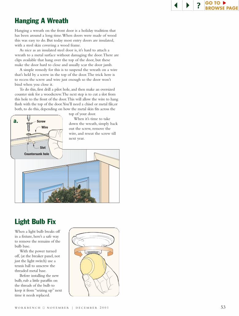
Light Bulb Fix
Hanging A Wreath
Countersunk hole
Screw
Wire
Slot
Hanging a wreath on the front door is a holiday tradition thathas been around a long time.When doors were made of woodthis was easy to do. But today most entry doors are insulated,with a steel skin covering a wood frame.
As nice as an insulated steel door is, it’s hard to attach awreath to a metal surface without damaging the door.There areclips available that hang over the top of the door, but thesemake the door hard to close and usually scar the door jamb.
A simple remedy for this is to suspend the wreath on a wirethat’s held by a screw in the top of the door.The trick here isto recess the screw and wire just enough so the door won’tbind when you close it.
To do this, first drill a pilot hole, and then make an oversizedcounter sink for a woodscrew.The next step is to cut a slot fromthis hole to the front of the door.This will allow the wire to hangflush with the top of the door.You’ll need a chisel or metal file,orboth, to do this, depending on how the metal skin fits across the
top of your door.When it’s time to take
down the wreath, simply backout the screw, remove thewire, and reseat the screw tillnext year.
When a light bulb breaks offin a fixture, here’s a safe wayto remove the remains of thebulb base.
With the power turnedoff, (at the breaker panel, notjust the light switch) use atennis ball to unscrew thethreaded metal base.
Before installing the newbulb, rub a little paraffin onthe threads of the bulb tokeep it from “seizing up” nexttime it needs replaced.
a.
53W O R K B E N C H ■■ N O V E M B E R | D E C E M B E R 2 0 0 1
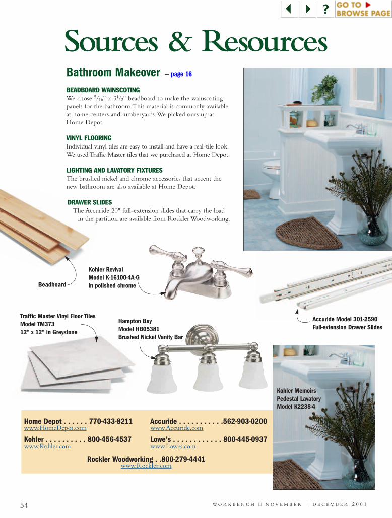
54 W O R K B E N C H ■■ N O V E M B E R | D E C E M B E R 2 0 0 1
Bathroom Makeover — page 16
Home Depot . . . . . . 770-433-8211www.HomeDepot.com
Kohler . . . . . . . . . . 800-456-4537www.Kohler.com
Accuride . . . . . . . . . . .562-903-0200www.Accuride.com
Lowe’s . . . . . . . . . . . . 800-445-0937www.Lowes.com
Sources & Resources
Beadboard
Traffic Master Vinyl Floor TilesModel TM37312" x 12" in Greystone
Hampton Bay Model HB05381 Brushed Nickel Vanity Bar
Accuride Model 301-2590Full-extension Drawer Slides
Kohler MemoirsPedestal LavatoryModel K2238-4
BEADBOARD WAINSCOTINGWe chose 5/16" x 31/2" beadboard to make the wainscotingpanels for the bathroom.This material is commonly availableat home centers and lumberyards.We picked ours up atHome Depot.
VINYL FLOORINGIndividual vinyl tiles are easy to install and have a real-tile look.We used Traffic Master tiles that we purchased at Home Depot.
LIGHTING AND LAVATORY FIXTURESThe brushed nickel and chrome accessories that accent thenew bathroom are also available at Home Depot.
DRAWER SLIDESThe Accuride 20" full-extension slides that carry the load
in the partition are available from Rockler Woodworking.
Rockler Woodworking . .800-279-4441www.Rockler.com
Kohler Revival Model K-16100-4A-Gin polished chrome
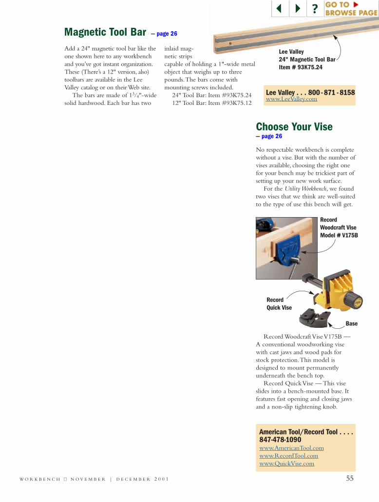
Lee Valley . . . 800 - 871 - 8158www.LeeValley.com
American Tool/Record Tool . . . .847-478-1090www.AmericanTool.comwww.RecordTool.comwww.QuickVise.com
Add a 24" magnetic tool bar like theone shown here to any workbenchand you’ve got instant organization.These (There’s a 12" version, also)toolbars are available in the LeeValley catalog or on their Web site.
The bars are made of 13/4"-widesolid hardwood. Each bar has two
inlaid mag-netic stripscapable of holding a 1"-wide metalobject that weighs up to threepounds.The bars come withmounting screws included.
24" Tool Bar: Item #93K75.2412" Tool Bar: Item #93K75.12
Magnetic Tool Bar — page 26
Choose Your Vise — page 26
No respectable workbench is completewithout a vise. But with the number ofvises available, choosing the right onefor your bench may be trickiest part ofsetting up your new work surface.
For the Utility Workbench, we foundtwo vises that we think are well-suitedto the type of use this bench will get.
RecordQuick Vise
Base
RecordWoodcraft ViseModel # V175B
Record Woodcraft Vise V175B —A conventional woodworking visewith cast jaws and wood pads forstock protection.This model isdesigned to mount permanentlyunderneath the bench top.
Record Quick Vise — This viseslides into a bench-mounted base. Itfeatures fast opening and closing jawsand a non-slip tightening knob.
Lee Valley24" Magnetic Tool BarItem # 93K75.24
55W O R K B E N C H ■■ N O V E M B E R | D E C E M B E R 2 0 0 1

56 W O R K B E N C H ■■ N O V E M B E R | D E C E M B E R 2 0 0 1
C R A F T S M A N S H I P
One “Stick” at a TimeIn the small town of Gladbrook, Iowa, craftsman Pat Acton patiently buildsincredible models to exact scale using ordinary matchsticks and gallons of glue.
Few craftsmen possess Pat Acton’s talent as a master builder.His creations span history’s honor roll: Columbus’ sailingship the Santa Maria, the U.S. Capitol, the Wright Brothers’
Kitty Hawk, the Civil War-era steam locomotive The General, theU.S.S. Iowa battleship, even the Challenger space shuttle.
But unlike modern engineering marvels, Acton’s replicasdon’t require massive sheets of steel or tons of lumber. Instead,
they’re all built with thousands of “tiny timbers” made fromwood matchsticks. His historic models are so unique that
Ripley’s Believe It or Not bought 19 for their museumsaround the world. His most recent work, a 12-foot-longU.S. Capitol, contains 500,000 matchsticks and tookabout 2,000 evening and weekend hours to complete.
“The models are a novelty,” Acton says. “That’swhy Ripley’s was so interested.” Novel, indeed.
To see more, go to WorkbenchMagazine.com
Pat Acton poses beside his matchstick CChhaalllleennggeerrspace shuttle, which contains 200,000 sticks.
Built stick by stick, the UU..SS..SS.. IIoowwaabattleship took 800 hours and nearly8,000 matchsticks to create.