three-dimensional slope stability: geometry effects · the slope stability analysis of complex...
TRANSCRIPT
The slope stability analysis of complex earth structures such as heap leach operations, waste rock piles, or tailings dams is becoming more common. Traditionally such analyses have been carried out using a two-dimensional (2D) limit equilibrium method. This type of analysis is simple and quick but does not take into account the three-dimensional (3D) aspects of the ge-ometry. There is also the slop aspect that a 3D factor of safety (FS) is typically higher than a 2D FS. Therefore there may be significant cost savings which can be realized in mining design by utilizing a 3D slope stability analysis. However there are additional analysis issues which come up in a 3D analysis. This paper examines the influence of surface topology in the form of concave or convex configurations of a simple and homogeneous modeling scenario to deter-mine the influence of geometry on a 3D slope stability analysis. The influence of groundwater is considered in the analysis as well as unsaturated suctions. Typical geometries are considered through a range of slope stability numbers.
1 INTRODUCTION Mining applications of slope stability in present operations typically involve the stability of heap leach operations, waste rock piles, or tailings dams. Such earth structures are commonly in parts of the world with high relief or at high elevations. The structures are also large and have a definite three-dimensional (3D) aspect to them. This has often required the application of a 3D slope stability methodology such that the adverse geometry of the earth structure can be consid-ered. 2D slope stability methods are typically not adequate for this type of analysis.
3D slope stability analysis by the limit equilibrium method (LEM) requires additional aspects of the analysis to be considered which are:
i) Shape of the slip surface in 3D (ellipsoidal or block) ii) Slip direction iii) Surface topography iv) Geo-strata and layering
This paper examines the effect of surface topography in a simple manner by the comparison
of plane, concave, or convex geometries. It is noteworthy that this type of analysis cannot be performed in 2D as the geometry is varying in the 3rd dimension. A series of parametric study on three-dimensional slope stability analyses was conducted to study the effect of soil parame-ters and geometry aspect on sensitivity of factor of safety.
Three-Dimensional Slope Stability: Geometry Effects
Krishna Bahadur Chaudhary SoilVision Systems Ltd., Saskatoon, SK, Canada
Vanessa Honorato Domingos Universidade Federal de Goias, Goiania, Brazil
Gilson Gitirana, Jr. Universidade Federal de Goias, Goiania, Brazil
Murray Fredlund SoilVision Systems Ltd., Saskatoon, SK, Canada
HaiHua Lu SoilVision Systems Ltd., Saskatoon, SK, Canada
ABSTRACT:
2 3D SLOPE STABILITY IN MINING When moving from 2D analysis to a 3D analysis in mining there are a number of additional as-pects of the model which must be considered. The shape of the slip surface must be considered more carefully (ellipsoidal / block). The aspect ratio of the ellipsoid must also be considered. Furthermore the slip direction also needs to be considered in the analysis. In addition to the shape of the slip surface the geometry of the ground surface and geo-strata can have an effect on the resulting slip surface and factor of safety.
This paper focuses on the potential effects of simple concave or convex geometries and their influence on the computed factor of safety.
2.1 Geometry effect – concave or convex
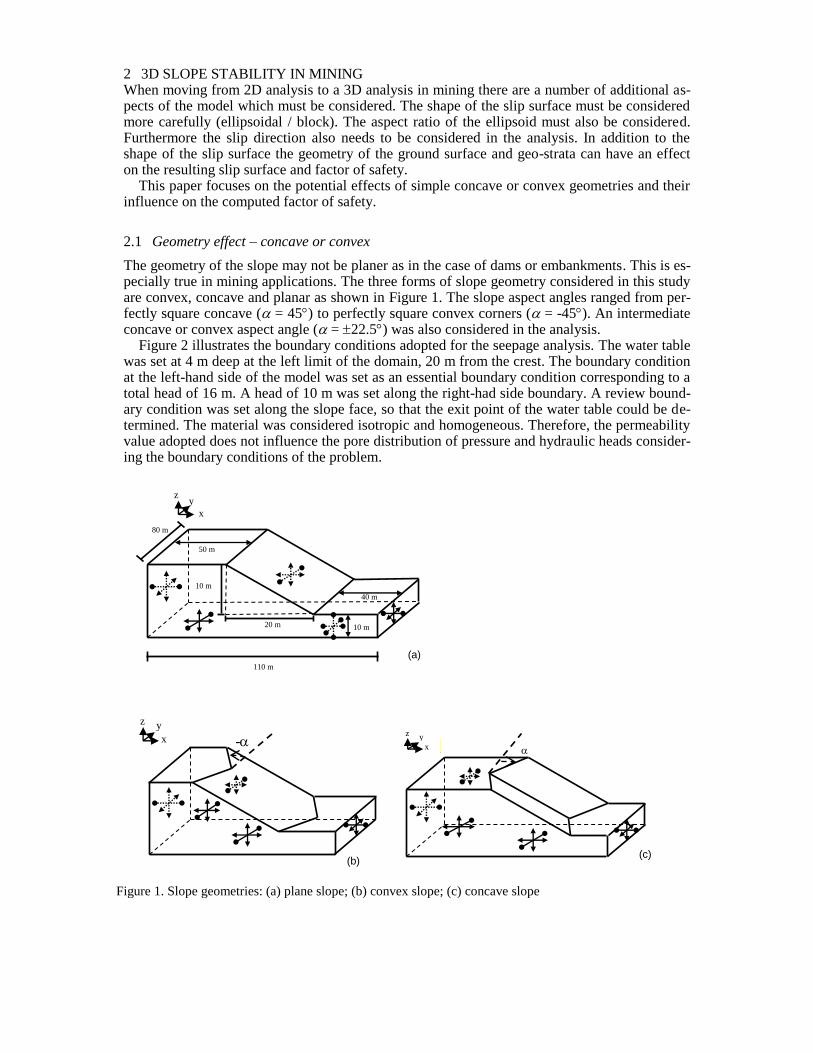
The geometry of the slope may not be planer as in the case of dams or embankments. This is es-pecially true in mining applications. The three forms of slope geometry considered in this study are convex, concave and planar as shown in Figure 1. The slope aspect angles ranged from per-fectly square concave ( = 45) to perfectly square convex corners ( = -45). An intermediate concave or convex aspect angle ( = 22.5) was also considered in the analysis.
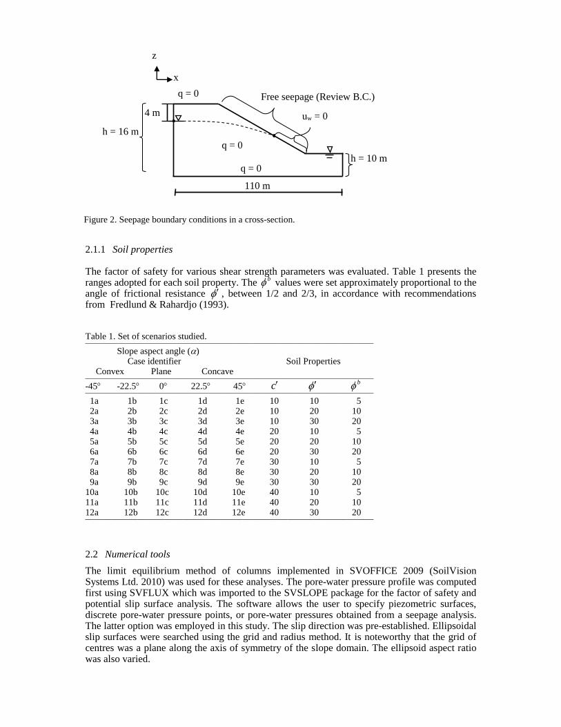
Figure 2 illustrates the boundary conditions adopted for the seepage analysis. The water table was set at 4 m deep at the left limit of the domain, 20 m from the crest. The boundary condition at the left-hand side of the model was set as an essential boundary condition corresponding to a total head of 16 m. A head of 10 m was set along the right-had side boundary. A review bound-ary condition was set along the slope face, so that the exit point of the water table could be de-termined. The material was considered isotropic and homogeneous. Therefore, the permeability value adopted does not influence the pore distribution of pressure and hydraulic heads consider-ing the boundary conditions of the problem.
x
10 m
80 m
40 m
10 m
110 m
20 m
(a)
50 m
z y
x
(b)
-
(c)
y
y x
z
Figure 1. Slope geometries: (a) plane slope; (b) convex slope; (c) concave slope
y z
2.1.1 Soil properties The factor of safety for various shear strength parameters was evaluated. Table 1 presents the ranges adopted for each soil property. The
b values were set approximately proportional to the angle of frictional resistance , between 1/2 and 2/3, in accordance with recommendations from Fredlund & Rahardjo (1993).
Table 1. Set of scenarios studied. _____________________________________________________________________________
Slope aspect angle () Case identifier Soil Properties
Convex Plane Concave _____________________________________________________________________________
-45 -22.5 0 22.5 45 c b
_____________________________________________________________________________
1a 1b 1c 1d 1e 10 10 5 2a 2b 2c 2d 2e 10 20 10 3a 3b 3c 3d 3e 10 30 20 4a 4b 4c 4d 4e 20 10 5 5a 5b 5c 5d 5e 20 20 10 6a 6b 6c 6d 6e 20 30 20 7a 7b 7c 7d 7e 30 10 5 8a 8b 8c 8d 8e 30 20 10 9a 9b 9c 9d 9e 30 30 20 10a 10b 10c 10d 10e 40 10 5 11a 11b 11c 11d 11e 40 20 10 12a 12b 12c 12d 12e 40 30 20 _____________________________________________________________________________
2.2 Numerical tools
The limit equilibrium method of columns implemented in SVOFFICE 2009 (SoilVision Systems Ltd. 2010) was used for these analyses. The pore-water pressure profile was computed first using SVFLUX which was imported to the SVSLOPE package for the factor of safety and potential slip surface analysis. The software allows the user to specify piezometric surfaces, discrete pore-water pressure points, or pore-water pressures obtained from a seepage analysis. The latter option was employed in this study. The slip direction was pre-established. Ellipsoidal slip surfaces were searched using the grid and radius method. It is noteworthy that the grid of centres was a plane along the axis of symmetry of the slope domain. The ellipsoid aspect ratio was also varied.
z
x
q = 0
q = 0
q = 0 Free seepage (Review B.C.)
uw = 0
h = 10 m
4 m
h = 16 m
110 m
Figure 2. Seepage boundary conditions in a cross-section.
The methods of analyses employed were as follows: Simplified Bishop (Bishop 1955); Janbu Simplified (Janbu 1973); Spencer (Spencer 1967); Morgenstern-Price (Morgenstern & Price 1965); and Generalized Limit Equilibrium (GLE) method (Fredlund et al. 1981). However, only the results from GLE method are included in this paper. To understand the effects of effective cohesion and effective friction angle on the slope stability, plots were made relating the factors of safety calculated for various sets of soil parameters in comparison with the stability number (Janbu 1954). The stability number can be calculated as follows:
tanStability number
H
c
(1)
where is unit weight of the soil, H is height of the slope, is effective friction angle, and c is effective cohesion.
3 RESULTS AND DISCUSSION
The results in the following sections present the influence of the geometry on the FOS. The crit-ical slip surface location is also searched for independently in each analysis.
3.1 Influence of three-dimensional geometry on the factor of safety and critical slip surface position
Figure 3 presents the results of three-dimensional slope stability analysis where the slope geom-etry varied from concave to convex. It can be seen that the concave shapes result in factors of safety that are higher than those obtained for convex geometries for the same material condi-tions. This type of result can be explained by the arching effect, which occurs in a pronounce manner as the slope becomes more concave. The overall effect of slope geometry was similar for all soil property combinations. The factor of safety tends to decrease as the slope shape be-comes closer to plane, reaching the lowest value when the geometry is perfectly plane. For plane geometry, the ellipsoid aspect ratio can go very large and SVSLOPE shows slip surfaces for plane slopes that always exceed the side boundaries. Attempts were made to increase the domain dimensions, but the resulting slip surface was found to increase with dimension. This result may be as per expectation since a plane; homogenous and symmetric slope is essentially a two-dimensional problem. This type of behavior is also a confirmation of an adequate perfor-mance of the software. The results for plane slopes were obtained using two-dimensional anal-yses because of this behavior.
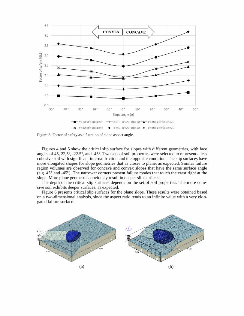
Figure 3. Factor of safety as a function of slope aspect angle.
Figures 4 and 5 show the critical slip surface for slopes with different geometries, with face
angles of 45, 22,5º, -22.5°, and -45°. Two sets of soil properties were selected to represent a less cohesive soil with significant internal friction and the opposite condition. The slip surfaces have more elongated shapes for slope geometries that as closer to plane, as expected. Similar failure region volumes are observed for concave and convex slopes that have the same surface angle (e.g. 45 and -45). The narrower corners present failure modes that touch the crest right at the slope. More plane geometries obviously result in deeper slip surfaces.
The depth of the critical slip surfaces depends on the set of soil properties. The more cohe-sive soil exhibits deeper surfaces, as expected.
Figure 6 presents critical slip surfaces for the plane slope. These results were obtained based on a two-dimensional analysis, since the aspect ratio tends to an infinite value with a very elon-gated failure surface.
(a) (b)
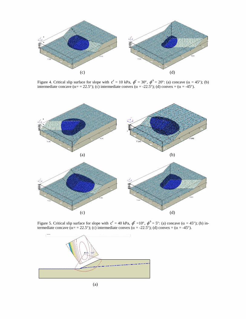
Figure 4. Critical slip surface for slope with c = 10 kPa, = 30, b = 20: (a) concave ( = 45); (b)
intermediate concave (= = 22.5); (c) intermediate convex ( = -22.5); (d) convex = ( = -45).
Figure 5. Critical slip surface for slope with c = 40 kPa, =10,
b = 5: (a) concave ( = 45); (b) in-termediate concave (= = 22.5); (c) intermediate convex ( = -22.5); (d) convex = ( = -45).
(c) (d)
(a) (b)
(c) (d)
(a)
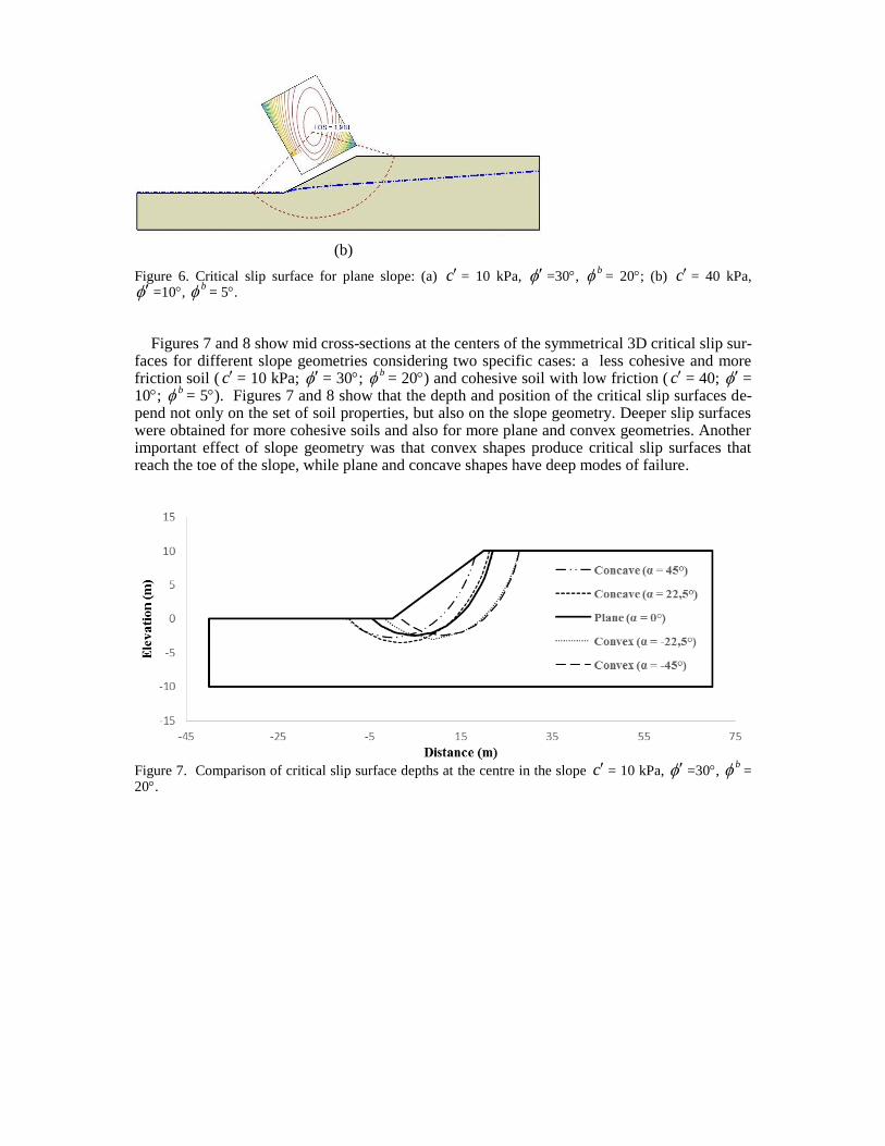
Figure 6. Critical slip surface for plane slope: (a) c = 10 kPa, =30,
b = 20; (b) c = 40 kPa, =10,
b = 5.
Figures 7 and 8 show mid cross-sections at the centers of the symmetrical 3D critical slip sur-
faces for different slope geometries considering two specific cases: a less cohesive and more friction soil ( c = 10 kPa; = 30;
b = 20) and cohesive soil with low friction ( c = 40; = 10;
b = 5). Figures 7 and 8 show that the depth and position of the critical slip surfaces de-pend not only on the set of soil properties, but also on the slope geometry. Deeper slip surfaces were obtained for more cohesive soils and also for more plane and convex geometries. Another important effect of slope geometry was that convex shapes produce critical slip surfaces that reach the toe of the slope, while plane and concave shapes have deep modes of failure.
Figure 7. Comparison of critical slip surface depths at the centre in the slope c = 10 kPa, =30,
b = 20.
(b)
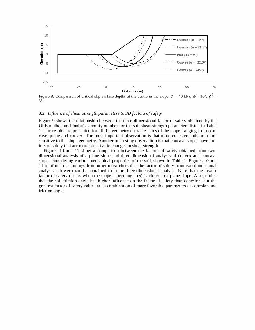
Figure 8. Comparison of critical slip surface depths at the centre in the slope c = 40 kPa, =10,
b = 5.
3.2 Influence of shear strength parameters to 3D factors of safety
Figure 9 shows the relationship between the three-dimensional factor of safety obtained by the GLE method and Janbu’s stability number for the soil shear strength parameters listed in Table 1. The results are presented for all the geometry characteristics of the slope, ranging from con-cave, plane and convex. The most important observation is that more cohesive soils are more sensitive to the slope geometry. Another interesting observation is that concave slopes have fac-tors of safety that are more sensitive to changes in shear strength.
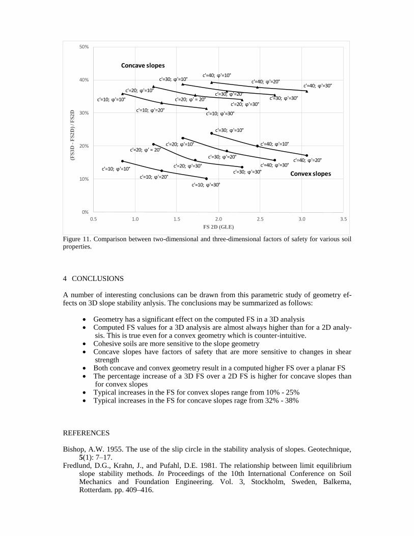
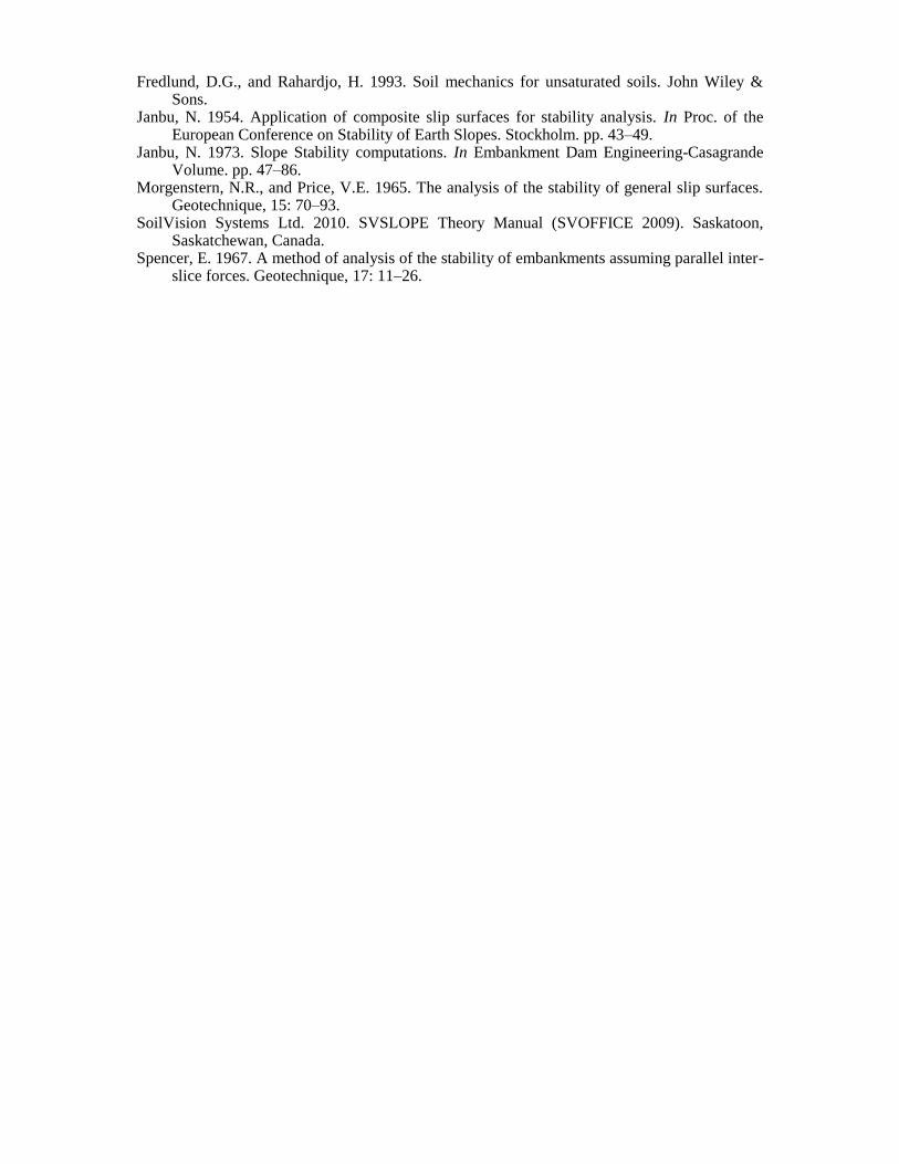
Figures 10 and 11 show a comparison between the factors of safety obtained from two-dimensional analysis of a plane slope and three-dimensional analysis of convex and concave slopes considering various mechanical properties of the soil, shown in Table 1. Figures 10 and 11 reinforce the findings from other researchers that the factor of safety from two-dimensional analysis is lower than that obtained from the three-dimensional analysis. Note that the lowest factor of safety occurs when the slope aspect angle (α) is closer to a plane slope. Also, notice that the soil friction angle has higher influence on the factor of safety than cohesion, but the greatest factor of safety values are a combination of more favorable parameters of cohesion and friction angle.
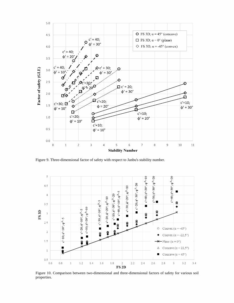
Figure 9. Three-dimensional factor of safety with respect to Janbu's stability number.
Figure 10. Comparison between two-dimensional and three-dimensional factors of safety for various soil properties.
0%
10%
20%
30%
40%
50%
0.5 1.0 1.5 2.0 2.5 3.0 3.5
(FS
3D
-F
S2
D)
/ F
S2
D
FS 2D (GLE)
c'=10; ϕ'=10°
c'=10; ϕ'=30°
c'=10; ϕ'=20°
c'=20; ϕ' = 20°c'=20; ϕ'=10°
c'=20; ϕ'=30°
c'=40; ϕ'=10°
c'=40; ϕ'=20°c'=40; ϕ'=30°
c'=30; ϕ'=20°
c'=30; ϕ'=10°
c'=30; ϕ'=30°
c'=10; ϕ'=10°
c'=10; ϕ'=30°c'=10; ϕ'=20°
c'=20; ϕ' = 20°
c'=20; ϕ'=10°
c'=20; ϕ'=30°
c'=40; ϕ'=10°c'=40; ϕ'=20°
c'=40; ϕ'=30°
c'=30; ϕ'=20°
c'=30; ϕ'=10°
c'=30; ϕ'=30°
Convex slopes
Concave slopes
Figure 11. Comparison between two-dimensional and three-dimensional factors of safety for various soil properties.
4 CONCLUSIONS
A number of interesting conclusions can be drawn from this parametric study of geometry ef-fects on 3D slope stability anlysis. The conclusions may be summarized as follows:
Geometry has a significant effect on the computed FS in a 3D analysis Computed FS values for a 3D analysis are almost always higher than for a 2D analy-
sis. This is true even for a convex geometry which is counter-intuitive. Cohesive soils are more sensitive to the slope geometry Concave slopes have factors of safety that are more sensitive to changes in shear
strength Both concave and convex geometry result in a computed higher FS over a planar FS The percentage increase of a 3D FS over a 2D FS is higher for concave slopes than
for convex slopes Typical increases in the FS for convex slopes range from 10% - 25% Typical increases in the FS for concave slopes rage from 32% - 38%
REFERENCES
Bishop, A.W. 1955. The use of the slip circle in the stability analysis of slopes. Geotechnique, 5(1): 7–17.
Fredlund, D.G., Krahn, J., and Pufahl, D.E. 1981. The relationship between limit equilibrium slope stability methods. In Proceedings of the 10th International Conference on Soil Mechanics and Foundation Engineering. Vol. 3, Stockholm, Sweden, Balkema, Rotterdam. pp. 409–416.
Fredlund, D.G., and Rahardjo, H. 1993. Soil mechanics for unsaturated soils. John Wiley & Sons.
Janbu, N. 1954. Application of composite slip surfaces for stability analysis. In Proc. of the European Conference on Stability of Earth Slopes. Stockholm. pp. 43–49.
Janbu, N. 1973. Slope Stability computations. In Embankment Dam Engineering-Casagrande Volume. pp. 47–86.
Morgenstern, N.R., and Price, V.E. 1965. The analysis of the stability of general slip surfaces. Geotechnique, 15: 70–93.
SoilVision Systems Ltd. 2010. SVSLOPE Theory Manual (SVOFFICE 2009). Saskatoon, Saskatchewan, Canada.
Spencer, E. 1967. A method of analysis of the stability of embankments assuming parallel inter-slice forces. Geotechnique, 17: 11–26.