thomas precession: where is the torque? another solution to the problem
TRANSCRIPT
This content has been downloaded from IOPscience. Please scroll down to see the full text.
Download details:
IP Address: 128.122.253.228
This content was downloaded on 21/10/2014 at 22:06
Please note that terms and conditions apply.
Thomas precession: where is the torque? Another solution to the problem
View the table of contents for this issue, or go to the journal homepage for more
2014 Eur. J. Phys. 35 065027
(http://iopscience.iop.org/0143-0807/35/6/065027)
Home Search Collections Journals About Contact us My IOPscience
Thomas precession: where is the torque?Another solution to the problem
Krzysztof Rebilas
Katedra Chemii i Fizyki, Uniwersytet Rolniczy im. Hugona Kołłataja wKrakowie. Al. Mickiewicza 21, 31-120 Kraków, Poland
E-mail: [email protected]
Received 7 July 2014, revised 27 August 2014Accepted for publication 8 September 2014Published 21 October 2014
AbstractSpecial relativity predicts that a spinning object with a constant angularmomentum in its rest frame, when transported around an orbit, will undergothe Thomas precession in the laboratory frame. As no torque is applied in therest frame of the gyroscope, it appears that the principle of conservation ofangular momentum is violated. In this paper, we show that in fact the Thomasprecession of the gyroscope is accompanied by a torque emerging due to theLorentz transformation of the force acting on segments of the gyroscope.Using the derived formula for torque, we find the standard expression for theThomas precession rate. Advantages of our approach compared to a work onthe same problem, by Muller (1992 Am. J. Phys. 60 313–317), are discussed.
Keywords: Thomas precession, torque, spin dynamics
1. Introduction
The special relativity effect known as the Thomas precession [1] means that a gyroscopeperforming a curvilinear motion will change orientation of its angular momentum. A directdemonstration of this phenomenon for a particle possessing spin can be found in [2–4]. Theproblem is that during this motion, no torque is applied to the precessing gyroscope in itsinstantaneous inertial rest frame, so it seems that the principle of angular momentum con-servation is not fulfilled. An attempt to solve this problem is undertaken by Muller [5], wherethe presence of torque emerges in the laboratory frame due to the gyroscope centre of massdisplacement. Nevertheless, some difficulties of this approach are discussed next.
In this work, we show that, despite the absence of torque in the rest frame of thegyroscope, a torque is present from the laboratory point of view. We derive the torque byreferring solely to the Lorentz transformation of forces acting on the gyroscope segments. Ourderivation, performed for a specific type of gyroscope, can be easily generalized to an
European Journal of Physics
Eur. J. Phys. 35 (2014) 065027 (5pp) doi:10.1088/0143-0807/35/6/065027
0143-0807/14/065027+05$33.00 © 2014 IOP Publishing Ltd Printed in the UK 1
arbitrary system having similar symmetry. The gyroscope spin dynamics governed by thederived torque enable us also to find the standard expression for the Thomas precession rate.
2. Origin of torque
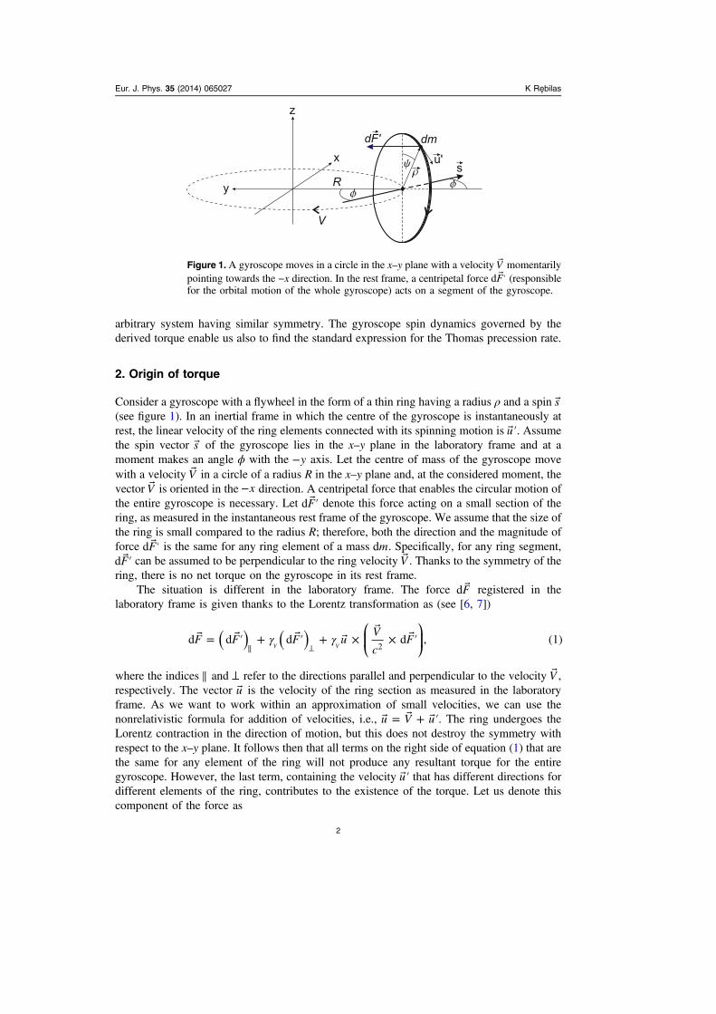
Consider a gyroscope with a flywheel in the form of a thin ring having a radius ρ and a spin s(see figure 1). In an inertial frame in which the centre of the gyroscope is instantaneously atrest, the linear velocity of the ring elements connected with its spinning motion is ′u . Assumethe spin vector s of the gyroscope lies in the x–y plane in the laboratory frame and at amoment makes an angle ϕ with the −y axis. Let the centre of mass of the gyroscope movewith a velocity V in a circle of a radius R in the x–y plane and, at the considered moment, thevector V is oriented in the −x direction. A centripetal force that enables the circular motion ofthe entire gyroscope is necessary. Let ′Fd denote this force acting on a small section of thering, as measured in the instantaneous rest frame of the gyroscope. We assume that the size ofthe ring is small compared to the radius R; therefore, both the direction and the magnitude offorce ′Fd is the same for any ring element of a mass md . Specifically, for any ring segment,
′Fd can be assumed to be perpendicular to the ring velocity V . Thanks to the symmetry of thering, there is no net torque on the gyroscope in its rest frame.
The situation is different in the laboratory frame. The force Fd registered in thelaboratory frame is given thanks to the Lorentz transformation as (see [6, 7])
⎛⎝⎜
⎞⎠⎟γ γ = ′ + ′ + ×
× ′
∥ ⊥( ) ( )F F F uV
cFd d d d , (1)
2V V
where the indices ∥ and ⊥ refer to the directions parallel and perpendicular to the velocity V ,respectively. The vector u is the velocity of the ring section as measured in the laboratoryframe. As we want to work within an approximation of small velocities, we can use thenonrelativistic formula for addition of velocities, i.e., = + ′u V u . The ring undergoes theLorentz contraction in the direction of motion, but this does not destroy the symmetry withrespect to the x–y plane. It follows then that all terms on the right side of equation (1) that arethe same for any element of the ring will not produce any resultant torque for the entiregyroscope. However, the last term, containing the velocity ′u that has different directions fordifferent elements of the ring, contributes to the existence of the torque. Let us denote thiscomponent of the force as
Figure 1.A gyroscope moves in a circle in the x–y plane with a velocity V momentarilypointing towards the −x direction. In the rest frame, a centripetal force ′Fd (responsiblefor the orbital motion of the whole gyroscope) acts on a segment of the gyroscope.
Eur. J. Phys. 35 (2014) 065027 K Rebilas
2
⎛⎝⎜
⎞⎠⎟γ = ′ ×
× ′F u
V
cFd d . (2)torque 2V
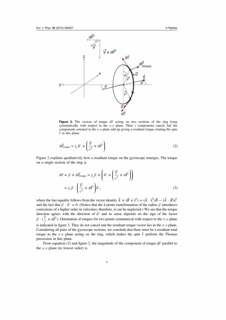
Figure 2 explains qualitatively how a resultant torque on the gyroscope emerges. The torqueon a single section of the ring is
⎛⎝⎜⎜
⎛⎝⎜
⎞⎠⎟
⎞⎠⎟⎟
⎛⎝⎜
⎞⎠⎟
τ ρ γ ρ
γ ρ
= × = × ′ ×
× ′
=
× ′ ′
F uV
cF
V
cF u
d d d
· d , (3)
torque 2
2
V
V
where the last equality follows from the vector identity × × = − A B C A C B A B C( ) ( · ) ( · )and the fact that ρ ′ =u· 0. (Notice that the Lorentz transformation of the radius ρ introducescorrections of a higher order in velocities; therefore, it can be neglected.) We see that the torquedirection agrees with the direction of ′u and its sense depends on the sign of the factor
ρ × ′F· ( d )V
c2. Orientation of torques for two points symmetrical with respect to the x–y plane
is indicated in figure 2. They do not cancel and the resultant torque vector lies in the x–y plane.Considering all pairs of the gyroscope sections, we conclude that there must be a resultant totaltorque in the x–y plane acting on the ring, which makes the spin s perform the Thomasprecession in this plane.
From equation (3) and figure 2, the magnitude of the component of torque τ d parallel tothe x–y plane (to lowest order) is
Figure 2. The vectors of torque τ d acting on two sections of the ring lyingsymmetrically with respect to the x–y plane. Their z components cancel, but thecomponents oriented in the x–y plane add up giving a resultant torque rotating the spins in this plane.
Eur. J. Phys. 35 (2014) 065027 K Rebilas
3
τ ρ ψ= ′ ′c
u V Fd1
d cos . (4)xy 22
The torque τd xy is perpendicular to the spin vector s and does not depend on the spin
orientation (the angle ϕ). Within the applied approximation, ′ =F mV Rd d 2 and λρ ψ=md d ,where λ is the linear mass density of the ring. Thus we obtain
τ λρ ψ ψ= ′c
uV
Rd
1cos d . (5)xy 2
23
2
Integration gives us the total torque in the x–y plane,
∫ ∫τ τ λρ ψ ψ ρ= = ′ = ′π
cu
V
R cm u
V
Rd
1cos d
1
2, (6)xy xy 2
23
0
22
2
3
where we have inserted the total mass of the ring πρλ=m 2 . Because τ = s td d , we have
τ ϕ= st
d
d. (7)xy
Making use of equation (6) and introducing the expression for spin ρ= ′s m u , it follows that
ϕ =t c
V
R
d
d
1
2. (8)
2
3
And finally, as the angular velocity in the orbital motion is ω = V R, we find that theprecession rate is
ω ϕ β ω≡ =t
d
d
1
2, (9)T
2
where β = V c. This is just the Thomas formula. Referring to figure 2, one can rewrite thisresult in a vectorial form as
ω β β =
× t
1
2
d
d. (10)T
In the context of the existing literature and erroneous expressions for the direction of theThomas precession (see [8] for discussion on this topic), our outcome is an additional andindependent confirmation of the correct formula presented in the original paper by Thomas[1] and referenced textbooks [2, 9].
3. Discussion
As the Thomas precession is a purely kinematical effect that follows from the Lorentztransformation properties, it may seem to be difficult to reconcile it with a dynamicalapproach where we deal with true forces and torques. If one remembers that no force in oneframe entails that there must be no force in any other frame, one could expect that the sameapplies to torque as well. This is why the Thomas rotation of spin, which proceeds in theabsence of any torque in the gyroscope rest frame, may seem paradoxical. Therefore, the goalof this work was to place the Thomas precession in the dynamical context and show it isconsistent within relativistic dynamics. In particular, we have demonstrated that there can beno torque in one frame and, for the same physical conditions, a torque occurs in another frameof reference where the Thomas rotation is observed. Further application of the formula for
Eur. J. Phys. 35 (2014) 065027 K Rebilas
4
torque can be regarded as a new method of deriving the Thomas precession rate throughoutthe dynamical approach.
The method proposed by Muller [5] for finding the torque acting on the gyroscopeconsists of pointing out the effect of displacement of the gyroscopeʼs centre of mass when it isobserved in the laboratory frame. (This fact can be neglected in our reasoning because itintroduces corrections of a higher order.) The problem is that the author establishes the torquewith respect to the centre of mass in a given frame of reference and it is known that the centreof mass is not a Lorentz covariant quantity [9]. In effect, the torque is found by Muller at theexpense of using different points of reference for the torque in the rest and laboratory frames.This approach has no justification in the relativistic theory of angular momentum dynamics.However, we refer to a work [10] by the author of this paper, where Mullerʼs method is morethoroughly explained, and justified in the context of the Bargmann, Michel and Telegdiequation [11] commonly used to describe spin dynamics.
We believe that the advantage of the approach shown in this paper is that it is based onlyon the relativistic force transformation so the presentation of torque exerted on the gyroscopeis devoid of any conceptual and theoretical difficulties. Also, the geometrical interpretation ofthe analysed effect is simple and intuitive.
As a final remark, let us indicate that a fully relativistic approach engages the entiretensor ∫= −μν μ ν ν μs x p x p V( )d describing spin of the gyroscope. It is important to note thatalthough the spatial components of τμνsd d are zero in the rest frame of the gyroscope (notorque), it does not mean that nothing happens in this frame. Namely, as can be shown by adirect calculation, the time components of the spin tensor change in time, τ ≠μsd d 00 . TheLorentz transformation of the tensor τμνsd d to the laboratory frame leads then to theoccurrence of the spatial components τSd dik different from zero, which is equivalent to thepresence of torque in the laboratory frame. Therefore, by using the angular momentum tensor,we obtain a fully consistent and complete description of the spin dynamics.
Acknowledgments
The author thanks P Prawda for his permanent assistance in elaborating the problem presentedin this paper.
References
[1] Thomas L H 1927 The kinematics of an electron with an axis Phil. Mag. 3 1–22[2] Jackson J D 1975 Classical Electrodynamics (New York: Wiley) Section 11.11[3] Rebilas K 2011 Simple approach to relativistic spin dynamics Am. J. Phys. 79 1064–67[4] Rebilas K 2011 Thomas precession and the Bargmann–Michel–Telegdi equation Found. Phys. 41
1800–9[5] Muller R A 1992 Thomas precession: where is the torque? Am. J. Phys. 60 313–7[6] Jackson J D 1975 Classical Electrodynamics (New York: Wiley) Section 12.2[7] Rebilas K 2006 A way to discover Maxwellʼs equations theoretically Found. Phys. Lett. 19
337–51[8] Rebilas K 2013 Comment on ‘Elementary analysis of the special relativistic combination of
velocities, Wigner rotation and Thomas precession’ Eur. J. Phys. 34 55–61[9] Møller C 1952 The Theory of Relativity (London: Oxford University Press) p 170[10] Rebilas K 2014 Thomas precession and torque Am. J. Phys. at press[11] Bargmann V, Michel L and Telegdi V L 1959 Precession of the polarization of particles moving in
a homogeneous electromagnetic field Phys. Rev. Lett. 2 435–6
Eur. J. Phys. 35 (2014) 065027 K Rebilas
5