third edition - zawiesia...
TRANSCRIPT
SDDCTEA PAMPHLET 55-22
LASHING HANDBOOK
FOR
MARINE MOVEMENTS
THIRD EDITION August 2005
(Electronically Revised July 2009)
Gary Horton
John T. Atwood Daniel J. Nonnemacher
______________________________________________________ MILITARY SURFACE DEPLOYMENT AND DISTRIBUTION COMMAND
TRANSPORTATION ENGINEERING AGENCY SCOTT AIR FORCE BASE, ILLINOIS
THIRD EDITION SDDCTEA PAMPHLET 55-22
ii
Director Military Surface Deployment and Distribution Command Transportation Engineering Agency ATTN: SDDCTEA - DPE (G. Horton) Building 1990, 709 Ward Drive Scott AFB, IL 62225
Telephone: DSN 770-5765, 618-220-5765, or 1-800-722-0727 FAX: DSN 770-5551 or 618-220-5551 E-mail: [email protected]
Make requests for additional copies or latest updated copy of these references can be downloaded from our website: http://www.tea.army.mil/pubs/pubs_order.htm
This book is part of the series started with MTMCTEA PAM 55-19, Tiedown
Handbook for Rail Movements. The books in the series are:
Handbooks for Military Movements PAM 55-19, Tiedown Handbook for Rail Movements PAM 55-20, Tiedown Handbook for Truck Movements PAM 55-21, Lifting and Tiedown Handbook for Helicopter Movements PAM 55-22, Marine Lifting and Lashing Handbook PAM 55-23, Tiedown Handbook for Containerized Movements PAM 55-24, Vehicle and Equipment Preparation Handbook for Fixed Wing Air
Movements
Planning and User’s Guide
PAM 70-1 Transportability for Better Deployability PAM 700-2 Logistics Handbook for Strategic Mobility Planning PAM 700-4 Vessel Characteristics for Shiploading PAM 700-5 Deployment Planning Guide PAM 700-6 Large, Medium Speed, Roll-On/Roll-Off Ships Users’ Manual PAM 700-7 Fast Sealift Ship Users’ Manual

THIRD EDITION SDDCTEA PAMPHLET 55-22
iii
Notes
THIRD EDITION SDDCTEA PAMPHLET 55-22
iv
Preface
This is the third edition of the pamphlet. It supersedes the second edition (March 1995) and MTMCTEA PAM 56-1, Marine Terminal Lifting Guidance. It contains some changes and improvements over the previous editions.
The end of the Cold War and the increasing threat of terrorism have enormously increased the scale and complexity of force projection. The threats can be asymmetric, and the probable battlefields can lie in areas surrounded by rugged terrain and served by fragile transportation infrastructure. While airlift is essential for moving people, supplies, and priority items, sealift is the primary means of moving military equipment. Because of the time required to deploy by sea and the relative weight and cube of the equipment involved, strategic sealift becomes the longest leg of the fort-to-foxhole deployment scenario. The purpose of this reference is to shorten this leg by providing standard marine terminal guidance for lifting and lashing military equipment on various strategic ships.
This pamphlet provides users with the proper lifting and lashing methods for loading and securing general and military equipment aboard marine vessels. The pamphlet includes equipment characteristics condensed from TACOM vehicle characteristics sheets, transportability guidance technical manuals (TGTMs), and field experience gained through participating in military exercises and deployments. The handbook does not include all military equipment found in the Army inventory. Rather, it covers military equipment commonly encountered during stevedore operations. Helicopters are not covered in this reference. We have published a separate reference, PAM 55-21, and have created an interactive CD which specifically addresses helicopters.
Throughout the pamphlet, warnings, cautions, and notes emphasize important or critical guidance.
THIRD EDITION SDDCTEA PAMPHLET 55-22
v
Table of Contents
Page Preface ........................................................................................................................... iv
TIEDOWN GUIDANCE SECTION I. Introduction ..................................................................................................1-1 II. Tips and Common Mistakes .........................................................................2-1 III. Lashing Hardware .........................................................................................3-1 IV. Lashing Wheeled Vehicles ...........................................................................4-1 V. Lashing Trailers ............................................................................................5-1 VI. Lashing Tracked Vehicles.............................................................................6-1 VII. Lashing Containers .......................................................................................7-1 APPENDIXES A. Cargo Restraint Criteria for Marine Transport: Development and Implementation ................................................................A-1 B. Calculation of Required Deck Strength ........................................................B-1 C. Recommended Blocking and Bracing Procedures ........................................C-1
THIRD EDITION SDDCTEA PAMPHLET 55-22
vi
Highlights an operating or maintenance procedure, practice, condition, statement, and so forth, that, if not strictly observed, could result in injury to or death of personnel.
Highlights an operating or maintenance procedure, practice, condition, statement, and so forth, that, if not strictly observed, could result in damage to, or destruction of, equipment or loss of mission effectiveness or long term health hazards to personnel.
NOTE
Highlights an essential operating or maintenance procedure, condition, or statement. SDDCTEA welcomes comments and recommendations for improving this pamphlet.
Readers may send their suggestions by letter or on a marked copy of a page(s) of the pamphlet to Director, Military Surface Deployment and Distribution Command Transportation Engineering Agency, ATTN: SDTE-DPE (G. Horton), Building 1990, 709 Ward Drive, Scott AFB, IL 62225. You may also email [email protected] to submit suggestions.
Questions can be answered by contacting us using the information from page ii. Please feel free to make copies of this pamphlet at your own discretion.
WARNING
CAUTION
THIRD EDITION SDDCTEA PAMPHLET 55-22
1-1
Section I. Introduction The reverse portion of this reference deals specifically with lifting military materiel during port operations. Military shippers are primarily responsible for marine lifting operations, to include procedures, hardware, and supervision. However, this responsibility changes once the materiel has been placed on board the ship. At that point, the ship’s officers assume responsibility for the equipment. Therefore, they typically have the final say as to how equipment is secured on the vessel. As a result, marine lashing procedures typically vary for different vessels, subject to the discretion of the individual inspecting the load and the anticipated voyage. The following sections will help alleviate this problem by standardizing tiedown procedures for strategic transport ships. Appendix A briefly describes the restraint criteria used to develop these procedures. Section II provides tips and common mistakes prior to loading vehicles, while loading them, and while securing them. Section III describes various types of lashing hardware and introduces appropriate geometric and strength considerations for the lashing assemblies. Sections IV through VII apply these considerations to wheeled vehicles, trailers, tracked vehicles, and watercraft, respectively. Each section includes diagrams and tables that illustrate the required lashing strengths, numbers, and patterns based on various equipment weight ranges. While applicable under most circumstances, the general guidance presented in Sections IV through VII has some practical limitations. Field situations sometimes present ships with inadequate tiedown points, equipment with missing shackles, and so forth. In such cases, creative lashings, extra tiedown materials, or blocking may be necessary.
THIRD EDITION SDDCTEA PAMPHLET 55-22
2-1
Section II. Tips and Common Mistakes A. Preparing Vehicles Prior to Loading 1. Make sure all lifting/tiedown shackles are attached to the vehicle. Do not use bumpers, axles, towing pintles, or towing hooks as points of attachment, except where specifically shown in the following sections. 2. Remove or band canvas and bows to prevent wind damage on the weather deck. 3. Secure all secondary cargo in the beds of trucks/trailers with appropriate restraint devices (banding, chain, straps, wire rope, and so forth) to counteract longitudinal (fore and aft), lateral (side to side), and vertical (up and down) forces encountered during lifting and tiedown operations. Bands should be at least ¾ by 0.020 inches. 4. Make sure fuel tanks are filled to the level specified in the SDDC port call message, but never more than ¾ full. 5. Make sure vehicle weights and dimensions are accurately measured and documented. Inaccurate measurement will throw-off load plans, creating potential trim and stability problems for the ship. Also, if vehicles are overloaded, shippers must be aware of the potential handling hazards to prevent safety risks. All movements of oversize, overweight, or special equipment must be according to DOD 4500.9-R, Defense Transportation Regulation (DTR), Part III, Mobility. 6. Using accurate equipment weight data, calculate weights hold-by-hold before loading to ensure you have adequate GM before loading. 7. Ensure all vehicle weapons and equipment are certified as cleared of ammunition and explosives.
THIRD EDITION SDDCTEA PAMPHLET 55-22
2-2
NOTE
GM refers to the ship’s metacentric height, which is an indicator of initial stability. Stability increases with the height of the GM and decreases as the GM is reduced. Excessive GM causes a ship to become “stiff,” decreasing the roll period and placing additional strain on the lashings. Without a proper GM, as determined from the ship’s stability book in conjunction with the Chief Officer/Master, ships will not leave port. If incorrect, ship’s officers may require cargo to be offloaded or redistributed. Careful, accurate planning can avoid such costly delays. B. Loading Vehicles 1. Store high density loads (that is, tracked vehicles) in lower holds. This helps keep GM in the safe range. As a general rule of thumb, 2/3 of the cargo weight should be below the waterline. 2. Lower holds must be filled with heavy cargo to avoid running out of GM before they cube or weigh out. 3. Maintain at least 6 inches between vehicles for clearance. 4. Check weight limitations of each deck (see Appendix B). 5. Make sure lumber is placed under steel treads to avoid metal-to-metal contact. 6. Avoid loading equipment athwartship. C. Securing Vehicles 1. Make sure transmissions are in neutral and parking brakes are set. 2. Use crossed chains to optimize lateral restraint. 3. Secure all gun tubes and turrets.
THIRD EDITION SDDCTEA PAMPHLET 55-22
2-3
4. Blocking is not required for military vehicles on ramps. The vehicle’s tiedown provisions are adequately designed to withstand dynamic forces in excess of those that could be imposed by ship motion.
NOTE
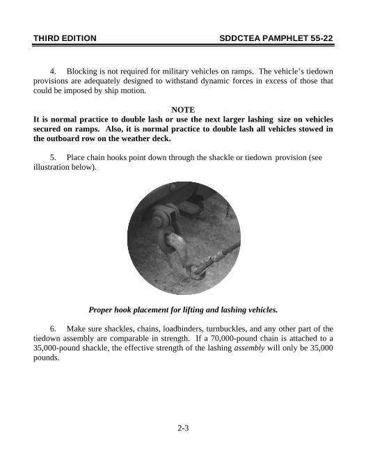
It is normal practice to double lash or use the next larger lashing size on vehicles secured on ramps. Also, it is normal practice to double lash all vehicles stowed in the outboard row on the weather deck. 5. Place chain hooks point down through the shackle or tiedown provision (see illustration below).
Proper hook placement for lifting and lashing vehicles.
6. Make sure shackles, chains, loadbinders, turnbuckles, and any other part of the tiedown assembly are comparable in strength. If a 70,000-pound chain is attached to a 35,000-pound shackle, the effective strength of the lashing assembly will only be 35,000 pounds.
THIRD EDITION SDDCTEA PAMPHLET 55-22
2-4
D. General 1. Lashings should be checked periodically to ensure they remain taut throughout the voyage. 2. Equipment stowed on the weather deck typically experiences the most severe accelerations because of ship motion. Therefore, the lashing capacities and angles shown in the following sections should be strictly adhered to on the weather deck. Equipment stowed in the lower holds will experience relatively low accelerations, so strict adherence is not as critical. For example, if the 25 degree angle criteria discussed later cannot be met because of the location and number of available deck fittings, angles between 15 and 60 degrees may be acceptable below the weather deck. 3. Lashings on fast sealift and large medium speed roll-on/roll-off (RORO) ships are color coded. Red lashings are rated at 10,000 pounds; blue lashings are 35,000-pound capacity; and the silver lashings are rated at 70,000 pounds. 4. Blocking and bracing is not required on ships with adequate deck fittings to accommodate the tiedown patterns shown in the following sections. However, for ships with few or no deck fittings, blocking may be the only means of securing the cargo. Appendix C addresses proper blocking and bracing procedures for such instances. 5. Make sure vehicles, shelters, and trailers are not loaded beyond their rated capacities. Overloads exceed the tested design limits of lifting/tiedown provisions and other structural members. This could pose a safety risk during transit.
THIRD EDITION SDDCTEA PAMPHLET 55-22
2-5
The following is a checklist to follow when loading and lashing vehicles.
Load and Tiedown Checklist • Ensure deck capacity is adequate prior to loading (see Appendix B). • Face vehicles in the same direction (do not load athwartship). • Leave at least 6 inches between vehicles. • Make sure parking brakes are set and transmission is in neutral. • Ensure all lashings are crossed and achieve approximately a 25 degree angle with
the deck. • Use symmetrical tiedown patterns. • Pull chain tight and attach hook, point down. • Tighten chain further with appropriate device. • Make sure chain is not kinked, twisted, or binding. • Do not secure chains to axles or springs unless the procedure is indicated in a
specific illustration. • Strike lashing with hammer or breaker bar and retighten as necessary.
NOTE When tying down helicopters, tighten the chain or strap only enough to remove slack; over tightening of chains or straps can result in structural damage to the helicopter.
THIRD EDITION SDDCTEA PAMPHLET 55-22
3-1
Section III. Lashing Hardware
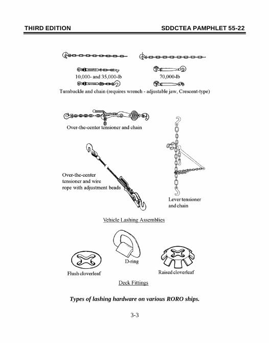
This section describes the lashing hardware and general tiedown requirements for roll-on/roll-off (RORO) and breakbulk vessels in the Ready Reserve Force (RRF), Maritime Security Program (MSP), Voluntary Intermodal Sealift Agreement (VISA) and under control of the Military Sealift Command (MSC). However, to keep instructions simple, we used only two categories of ships: fast sealift ships/large, medium speed RORO ships (FSS/LMSR) and “Other” ships. The “Other” category applies to all ships other than the FSS and LMSR classes. The FSS and LMSR were treated separately because of their relative size and stability under storm sea conditions. Page 3-3 shows some of the various types of lashing gear that are available on the RORO ships. Breakbulk ships do not usually have lashing gear, so you may use blocking (see Appendix C), wire rope, turnbuckles, or shipper supplied chains of the appropriate strength and number. No matter what lashing gear is used, the actual tiedown procedure will depend on four things: strength of the lashing assembly; strength of the deck fitting; weight of the vehicle being restrained; and the angles of the lashing relative to the vehicle and the deck. We optimized the angles for lashing military vehicles to get the best use of the available lashing gear. Pages 3-4 through 3-6 show the recommended angles for lashing equipment. The actual angle of the lashing chain will be determined by the placement of the vehicle to be lashed and the relative location of the deck fittings. When you have a choice of several deck fittings, use the one that most closely results in the angles given on pages 3-4 through 3-6. If you cannot get close to the angles shown, use the next higher lashing size, or add four more lashings. In the vehicle lashing sections, the lashing shown is meant to represent whatever lashing gear is available. You may have to use multiples of lashing gear to get the strength shown for a particular vehicle.
THIRD EDITION SDDCTEA PAMPHLET 55-22
3-2
In some cases, a single line in an illustration may actually represent two separate lashings. Tables 3-1 and 3-2 give the strength capabilities of various lashing gear on FSS/LMSR and other ships, respectively. These tables can be used to determine the lashing required for any item based on the item’s weight. For heavier vehicles, use the strongest lashing gear available. However, if a table or diagram requires 70,000-pound strength, but only 35,000-pound gear is available, use twice as many 35,000-pound devices as the number of 70,000-pound devices required.
NOTE When using multiple lashings, always use the same size and type. If you mix types or sizes, the strengths will not add effectively, and the lashings may fail. The lashing requirements and diagrams documented herein are based on sea state 7 conditions (between 25 and 40 foot seas depending on wind speed) and are necessarily conservative to account for the possibility of encountering rough seas. They apply to all ships listed in the Integrated Computerized Deployment System (ICODES). Therefore, this is a general guide that illustrates the maximum number of lashings that should be applied to safely secure equipment in stormy seas. However, in all matters of lashing onboard ships, the Master of the ship, as the person legally responsible for all activities onboard his/her ship, is the final approval authority. Frequently, the anticipated voyage will encounter lesser seas such that the actual required lashing size and number may be significantly lower. In such cases, the Master may appropriately determine that the requirements documented herein are overly conservative based on specific ship and/or voyage conditions. SDDCTEA is available to provide specific technical support on a case-by-case basis. For such support, contact Mr. Gary Horton at DSN 770-5765 or (618) 220-5765; Mr. John Newman at DSN 770-5263 or (618) 220-5765; or toll free at 1-800-722-0727.
THIRD EDITION SDDCTEA PAMPHLET 55-22
3-3
Types of lashing hardware on various RORO ships.
THIRD EDITION SDDCTEA PAMPHLET 55-22
3-4
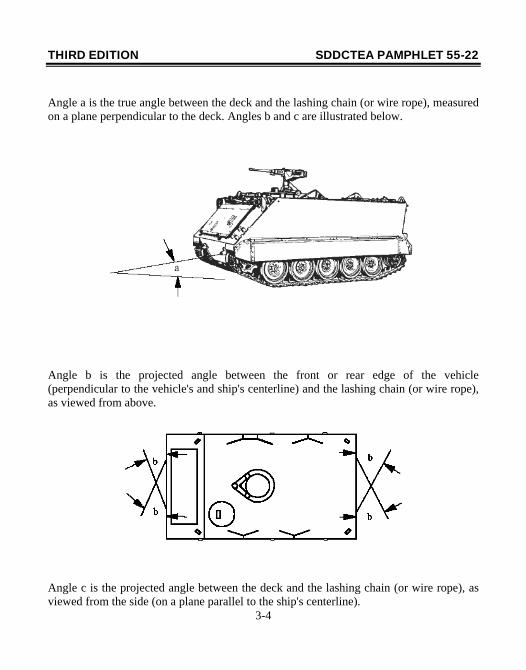
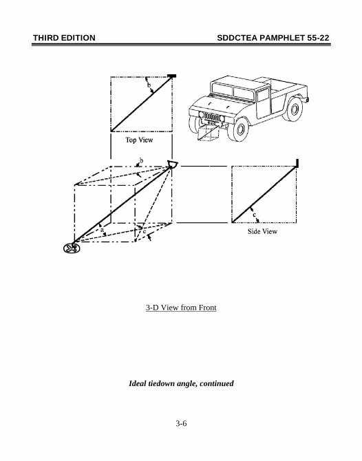
Angle a is the true angle between the deck and the lashing chain (or wire rope), measured on a plane perpendicular to the deck. Angles b and c are illustrated below.
Angle b is the projected angle between the front or rear edge of the vehicle (perpendicular to the vehicle's and ship's centerline) and the lashing chain (or wire rope), as viewed from above.
Angle c is the projected angle between the deck and the lashing chain (or wire rope), as viewed from the side (on a plane parallel to the ship's centerline).
THIRD EDITION SDDCTEA PAMPHLET 55-22
3-5
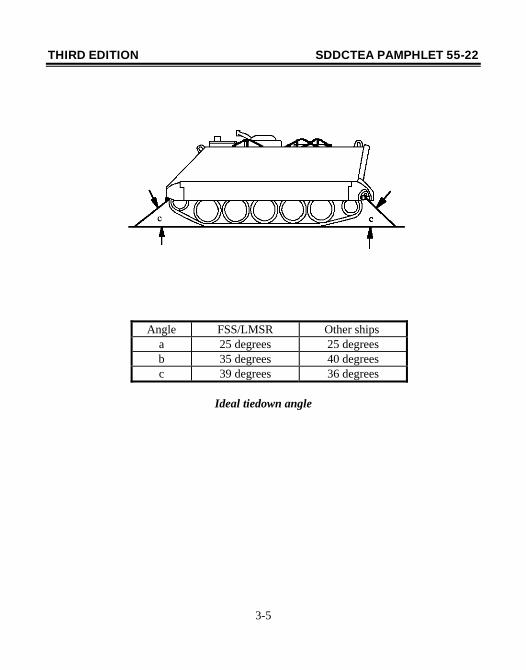
Angle FSS/LMSR Other ships
a 25 degrees 25 degrees b 35 degrees 40 degrees c 39 degrees 36 degrees
Ideal tiedown angle
THIRD EDITION SDDCTEA PAMPHLET 55-22
3-6
3-D View from Front
Ideal tiedown angle, continued
THIRD EDITION SDDCTEA PAMPHLET 55-22
3-7
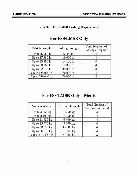
Table 3-1. FSS/LMSR Lashing Requirements.
For FSS/LMSR Only
Vehicle Weight Lashing Strength Total Number of Lashings Required
Up to 8,930 lb 5,000 lb 4 Up to 17,860 lb 10,000 lb 4 Up to 25,180 lb 14,100 lb 4 Up to 30,360 lb 17,000 lb 4 Up to 62,510 lb 35,000 lb 4 Up to 125,020 lb 70,000 lb 4 Up to 250,040 lb 70,000 lb 8
For FSS/LMSR Only – Metric
Vehicle Weight Lashing Strength Total Number of Lashings Required
Up to 4 050 kg 2 250 kg 4 Up to 8 100 kg 4 550 kg 4 Up to 11 420 kg 6 400 kg 4 Up to 13 770 kg 7 700 kg 4 Up to 28 350 kg 15 900 kg 4 Up to 56 710 kg 31 750 kg 4
Up to 113 420 kg 31 750 kg 8
THIRD EDITION SDDCTEA PAMPHLET 55-22
3-8
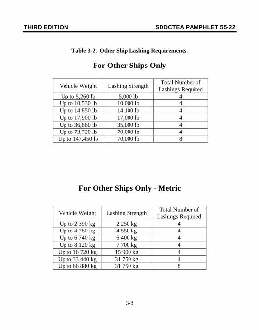
Table 3-2. Other Ship Lashing Requirements.
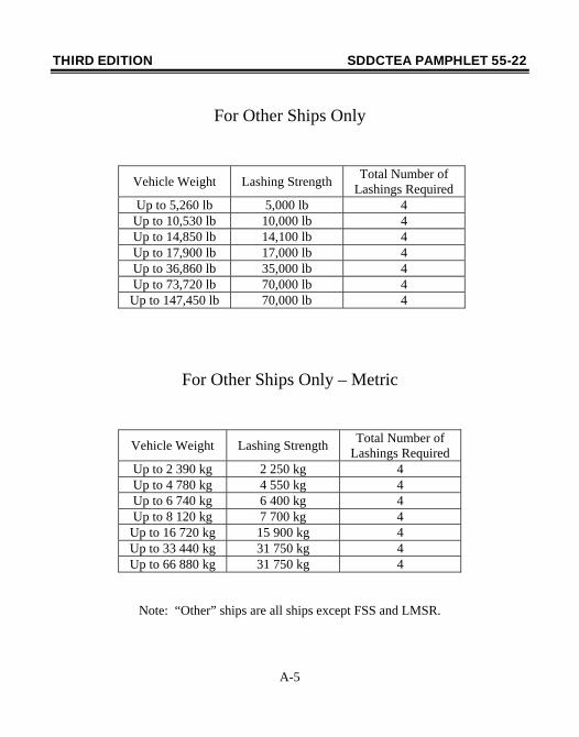
For Other Ships Only
Vehicle Weight Lashing Strength Total Number of Lashings Required
Up to 5,260 lb 5,000 lb 4 Up to 10,530 lb 10,000 lb 4 Up to 14,850 lb 14,100 lb 4 Up to 17,900 lb 17,000 lb 4 Up to 36,860 lb 35,000 lb 4 Up to 73,720 lb 70,000 lb 4 Up to 147,450 lb 70,000 lb 8
For Other Ships Only - Metric
Vehicle Weight Lashing Strength Total Number of Lashings Required
Up to 2 390 kg 2 250 kg 4 Up to 4 780 kg 4 550 kg 4 Up to 6 740 kg 6 400 kg 4 Up to 8 120 kg 7 700 kg 4
Up to 16 720 kg 15 900 kg 4 Up to 33 440 kg 31 750 kg 4 Up to 66 880 kg 31 750 kg 8
THIRD EDITION SDDCTEA PAMPHLET 55-22
4-1
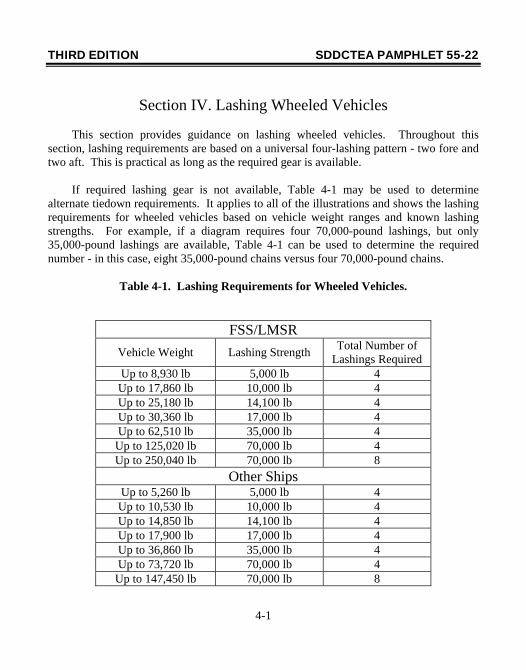
Section IV. Lashing Wheeled Vehicles
This section provides guidance on lashing wheeled vehicles. Throughout this section, lashing requirements are based on a universal four-lashing pattern - two fore and two aft. This is practical as long as the required gear is available. If required lashing gear is not available, Table 4-1 may be used to determine alternate tiedown requirements. It applies to all of the illustrations and shows the lashing requirements for wheeled vehicles based on vehicle weight ranges and known lashing strengths. For example, if a diagram requires four 70,000-pound lashings, but only 35,000-pound lashings are available, Table 4-1 can be used to determine the required number - in this case, eight 35,000-pound chains versus four 70,000-pound chains.
Table 4-1. Lashing Requirements for Wheeled Vehicles.
FSS/LMSR Vehicle Weight Lashing Strength Total Number of
Lashings Required Up to 8,930 lb 5,000 lb 4 Up to 17,860 lb 10,000 lb 4 Up to 25,180 lb 14,100 lb 4 Up to 30,360 lb 17,000 lb 4 Up to 62,510 lb 35,000 lb 4
Up to 125,020 lb 70,000 lb 4 Up to 250,040 lb 70,000 lb 8
Other Ships Up to 5,260 lb 5,000 lb 4 Up to 10,530 lb 10,000 lb 4 Up to 14,850 lb 14,100 lb 4 Up to 17,900 lb 17,000 lb 4 Up to 36,860 lb 35,000 lb 4 Up to 73,720 lb 70,000 lb 4
Up to 147,450 lb 70,000 lb 8
THIRD EDITION SDDCTEA PAMPHLET 55-22
4-2
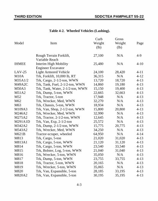
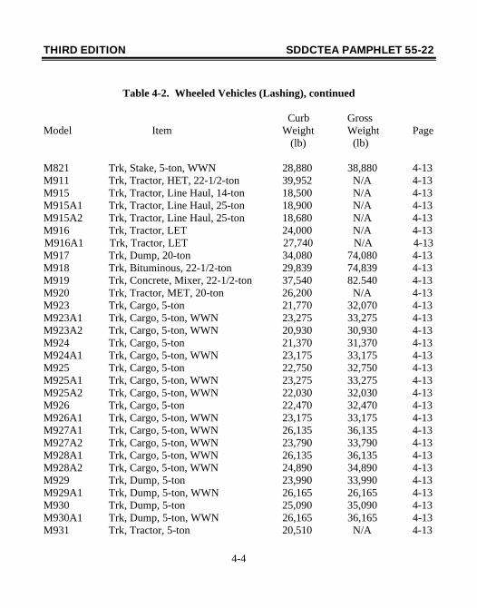
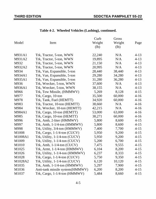
Note that in some cases, diagrams are shown for unique vehicles and in others for vehicles that illustrate generic lashing procedures. For example, page 4-26 illustrates a heavy road grader so that the dunnage requirement for the grader blade is not overlooked. Page 4-13, on the other hand, is a generic cargo truck that applies to all 2-1/2- and 5-ton trucks. This approach helps reduce the size and complexity of the pamphlet. Table 4-2 lists wheeled vehicles covered in this handbook.
THIRD EDITION SDDCTEA PAMPHLET 55-22
4-3
Table 4-2. Wheeled Vehicles (Lashing).
Curb Gross Model Item Weight Weight Page (lb) (lb) Rough Terrain Forklift, 27,100 N/A 4-9 Variable Reach IHMEE Interim High Mobility 25,480 N/A 4-10 Engineer Excavator LAV-25 Light Armored Vehicle 24,100 28,420 4-11 M10A Trk, Forklift, 10,000 lb, RT 36,315 N/A 4-12 M35A1/2 Trk, Cargo, 2-1/2-ton, WWN 13,720 18,720 4-13 M49A2C Trk, Tank, Fuel, 2-1/2-ton, WWN 14,860 19,180 4-13 M50A3 Trk, Tank, Water, 2-1/2-ton, WWN 15,150 19,400 4-13 M51A2 Trk, Dump, 5-ton, WWN 22,665 32,663 4-13 M52 Trk, Tractor, 5-ton 17,948 N/A 4-13 M62 Trk, Wrecker, Med, WWN 32,270 N/A 4-13 M63 Trk, Chassis, 5-ton, WWN 18,934 N/A 4-13 M109A3 Trk, Van, Shop, 2-1/2-ton, WWN 15,800 20,800 4-13 M246A2 Trk, Wrecker, Med, WWN 32,990 N/A 4-13 M275A2 Trk, Tractor, 2-1/2-ton, WWN 12,645 N/A 4-13 M291A1D Trk, Van, Exp, 2-1/2-ton 25,572 N/A 4-13 M342A2 Trk, Dump, 2-1/2-ton, WWN 15,775 20,775 4-13 M543A2 Trk, Wrecker, Med, WWN 34,250 N/A 4-13 M621B Tractor-scraper, wheeled 64,950 N/A 4-14 M813 Trk, Cargo, 5-ton 21,020 31,020 4-13 M813A1 Trk, Cargo, 5-ton, WWN 21,120 31,120 4-13 M814 Trk, Cargo, 5-ton, WWN 23,540 33,540 4-13 M815 Trk, Bolster, Log, 5-ton, WWN 21,040 31,040 4-13 M816 Trk, Wrecker, 5-ton, WWN 35,050 N/A 4-13 M817 Trk, Dump, 5-ton, WWN 23,755 33,755 4-13 M818 Trk, Tractor, 5-ton, WWN 20,165 N/A 4-13 M819 Trk, Wrecker, 5-ton, WWN 35,065 N/A 4-13 M820 Trk, Van, Expansible, 5-ton 28,185 33,195 4-13 M820A2 Trk, Van, Expansible, 5-ton 30,195 35,195 4-13
THIRD EDITION SDDCTEA PAMPHLET 55-22
4-4
Table 4-2. Wheeled Vehicles (Lashing), continued
Curb Gross Model Item Weight Weight Page (lb) (lb) M821 Trk, Stake, 5-ton, WWN 28,880 38,880 4-13 M911 Trk, Tractor, HET, 22-1/2-ton 39,952 N/A 4-13 M915 Trk, Tractor, Line Haul, 14-ton 18,500 N/A 4-13 M915A1 Trk, Tractor, Line Haul, 25-ton 18,900 N/A 4-13 M915A2 Trk, Tractor, Line Haul, 25-ton 18,680 N/A 4-13 M916 Trk, Tractor, LET 24,000 N/A 4-13 M916A1 Trk, Tractor, LET 27,740 N/A 4-13 M917 Trk, Dump, 20-ton 34,080 74,080 4-13 M918 Trk, Bituminous, 22-1/2-ton 29,839 74,839 4-13 M919 Trk, Concrete, Mixer, 22-1/2-ton 37,540 82.540 4-13 M920 Trk, Tractor, MET, 20-ton 26,200 N/A 4-13 M923 Trk, Cargo, 5-ton 21,770 32,070 4-13 M923A1 Trk, Cargo, 5-ton, WWN 23,275 33,275 4-13 M923A2 Trk, Cargo, 5-ton, WWN 20,930 30,930 4-13 M924 Trk, Cargo, 5-ton 21,370 31,370 4-13 M924A1 Trk, Cargo, 5-ton, WWN 23,175 33,175 4-13 M925 Trk, Cargo, 5-ton 22,750 32,750 4-13 M925A1 Trk, Cargo, 5-ton, WWN 23,275 33,275 4-13 M925A2 Trk, Cargo, 5-ton, WWN 22,030 32,030 4-13 M926 Trk, Cargo, 5-ton 22,470 32,470 4-13 M926A1 Trk, Cargo, 5-ton, WWN 23,175 33,175 4-13 M927A1 Trk, Cargo, 5-ton, WWN 26,135 36,135 4-13 M927A2 Trk, Cargo, 5-ton, WWN 23,790 33,790 4-13 M928A1 Trk, Cargo, 5-ton, WWN 26,135 36,135 4-13 M928A2 Trk, Cargo, 5-ton, WWN 24,890 34,890 4-13 M929 Trk, Dump, 5-ton 23,990 33,990 4-13 M929A1 Trk, Dump, 5-ton, WWN 26,165 26,165 4-13 M930 Trk, Dump, 5-ton 25,090 35,090 4-13 M930A1 Trk, Dump, 5-ton, WWN 26,165 36,165 4-13 M931 Trk, Tractor, 5-ton 20,510 N/A 4-13
THIRD EDITION SDDCTEA PAMPHLET 55-22
4-5
Table 4-2. Wheeled Vehicles (Lashing), continued. Curb Gross Model Item Weight Weight Page (lb) (lb) M931A1 Trk, Tractor, 5-ton, WWN 22,240 N/A 4-13 M931A2 Trk, Tractor, 5-ton, WWN 19,895 N/A 4-13 M932 Trk, Tractor, 5-ton, WWN 21,150 N/A 4-13 M932A2 Trk, Tractor, 5-ton, WWN 20,995 N/A 4-13 M934 Trk, Van, Expansible, 5-ton 28,440 38,440 4-13 M934A1 Trk, Van, Expansible, 5-ton 29,280 34,280 4-13 M935A1 Trk, Van, Expansible, 5-ton 31,280 36,280 4-13 M936 Trk, Wrecker, 5-ton, WWN 37,600 N/A 4-13 M936A1 Trk, Wrecker, 5-ton, WWN 38,155 N/A 4-13 M966 Trk, Tow Missile, (HMMWV) 5,269 8,128 4-15 M977 Trk, Cargo, 10-ton 35,500 60,000 4-16 M978 Trk, Tank, Fuel (HEMTT) 34,920 60,000 4-16 M983 Trk, Tractor, 10-ton (HEMTT) 38,660 N/A 4-16 M984 Trk, Wrecker, 10-ton (HEMTT) 42,215 N/A 4-16 M984A1 Trk, Cargo, 10-ton (HEMTT) 53,000 63,000 4-16 M985 Trk, Cargo, 10-ton (HEMTT) 38,271 60,000 4-16 M996 Trk, Amb, 2-liter (HMMWV) 5,800 8,600 4-15 M997 Trk, Amb, 1-1/4-ton (HMMWV) 5,800 8,600 4-15 M998 Trk, Utility, 3/4-ton (HMMWV) 7,400 7,700 4-15 M1008 Trk, Cargo, 1-1/4-ton (CUCV) 5,950 9,200 4-15 M1008A1 Trk, Utility, 1-1/4-ton (CUCV) 5,950 9,200 4-15 M1009 Trk, Utility, 1-1/4-ton (CUCV) 5,200 6,700 4-15 M1010 Trk, Amb, 1-1/4-ton (CUCV) 7,475 9,555 4-15 M1025 Trk, Armt, 1-1/4-ton (HMMWV) 6,104 8,200 4-15 M1026 Trk, Utility, 1-1/4-ton (HMMWV) 6,237 8,333 4-15 M1028 Trk, Cargo, 1-1/4-ton (CUCV) 5,750 9,350 4-15 M1028A2 Trk, Utility, 1-1/4-ton (CUCV) 6,120 10,120 4-15 M1035 Trk, Amb, 1-1/4-ton (HMMWV) 5,297 7,900 4-15 M1036 Anti-tank missile system (HMMWV) 6,200 8,200 4-15 M1037 Trk, Cargo, 1-1/4-ton (HMMWV) 5,484 8,660 4-15
THIRD EDITION SDDCTEA PAMPHLET 55-22
4-6
Table 4-2. Wheeled Vehicles (Lashing), continued. Curb Gross Model Item Weight Weight Page (lb) (lb) M1038 Trk, Utility, 1-1/4-ton (HMMWV) 5,591 7,833 4-15 M1042 Trk, Shelter, 1-1/4-ton (HMMWV) 5,617 8,660 4-15 M1043 Trk, Armt, 1-1/4-ton (HMMWV) 7,673 8,473 4-15 M1044 Trk, Armt, 1-1/4-ton (HMMWV) 7,803 8,600 4-15 M1045 Trk, TOW, 1-1/4-ton (HMMWV) 7,549 8,149 4-15 M1046 Trk, TOW, 1-1/4-ton (HMMWV) 7,679 8,729 4-15 M1070 HET Tractor 40,999 N/A 4-13 M1074 PLS Truck w/flatrack 55,010 88,000 4-17 M1075 PLS Truck w/flatrack 49,520 82,960 4-17 M1076 PLS Trailer w/flatrack 16,530 49,520 4-19 M1078 LMTV, Cargo 18,137 23,137 4-11 M1079 LMTV, Van 19,879 24,879 4-11 M1081 LMTV, Cargo, A/D 19,379 24,379 4-11 M1083 MTV, Cargo, wwn 21,473 31,474 4-11 M1083 MTV, Cargo 20,497 30,497 4-11 M1084 MTV, Cargo, w/MHE 24,510 34,510 4-11 M1085 MTV, Long Cargo 22,978 32,978 4-11 M1086 MTV, Long Cargo, w/MHE 26,076 36,076 4-11 M1088 MTV, Tractor 19,251 N/A 4-11 M1089 MTV, Wrecker 33,810 N/A 4-11 M1090 MTV, Dump 23,082 33,082 4-11 M1093 MTV, Cargo, A/D 22,653 32,654 4-11 M1094 MTV, Dump, A/D 24,296 34,296 4-11 M1097 HHV, HMMWV Heavy Variant 5,600 10,001 4-15 M1113 Trk, Utility, Expanded 6,400 11,500 4-20 Capacity (HMMWV) M1114 Armt Carrier, Expanded 9,800 12,100 4-20 Capacity (HMMWV) M1117 Armored Security Vehicle (ASV) 12,428 12,428 4-11
THIRD EDITION SDDCTEA PAMPHLET 55-22
4-7
Table 4-2. Wheeled Vehicles (Lashing), continued. Curb Gross Model Item Weight Weight Page (lb) (lb) M1120 Heavy Expanded Mobility Tactical 35,300 57,300 4-17 Trk (HEMTT) M1126 Stryker Infantry Carrier Vehicle 35,574 40,836 4-21 with Slat Armor 39,574 44,836 4-21 M1127 Stryker Reconnaissance Vehicle 36,403 40,168 4-21 with Slat Armor 40,403 44,168 4-21 M1128 Stryker Mobile Gun System 37,311 43,172 4-21 with Slat Armor 41,754 47,172 4-21 M1129 Stryker Mortar Carrier 38,807 41,923 4-21 with Slat Armor 42,807 45,923 4-21 M1130 Stryker Commander’s Vehicle 36,614 39,243 4-21 with Slat Armor 40,614 43,243 4-21 M1131 Stryker Fire Support Vehicle 36,364 38,743 4-21 with Slat Armor 40,364 42,743 4-21 M1132 Stryker Engineering Squad Vehicle 36,425 42,166 4-21 with Slat Armor 40,425 46,166 4-21 M1133 Stryker Medical Evacuation Vehicle 37,480 39,720 4-21 with Slat Armor 41,480 43,720 4-21 M1134 Stryker Anti-Tank Guided Missile 38,959 41,478 4-21 with Slat Armor 42,959 45,478 4-21 M1151 Trk, Utility, Expanded 7,460 11,500 4-20 Capacity (HMMWV) M1152 Trk, Utility, Expanded 6,400 11,500 4-20 Capacity (HMMWV) MT250 Crane, Truck-Mounted, 25-ton 65,800 N/A 4-22 MT300 Crane, Truck-Mounted, 35-ton 69,910 N/A 4-22 MW24C Loader, Scoop, Wheel 26,540 N/A 4-12
THIRD EDITION SDDCTEA PAMPHLET 55-22
4-8
Table 4-2. Wheeled Vehicles (Lashing), continued. Curb Gross Model Item Weight Weight Page (lb) (lb) RTCH Rough Terrain Container 118,040 N/A 4-23 Handler RT240 Rough Terrain Container 118,000 N/A 4-24 Handler (RTCH) Kalmar SEE Small Emplacement Excavator 15,920 N/A 4-25 130G Grader, road, heavy 31,900 N/A 4-26 7-1/2-ton Crane, Rough Terrain 24,230 N/A 4-27
THIRD EDITION SDDCTEA PAMPHLET 55-22
4-9
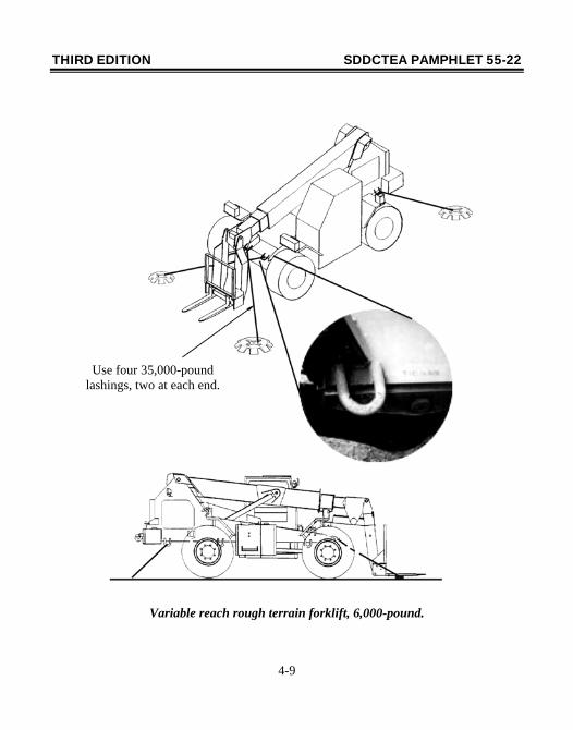
Variable reach rough terrain forklift, 6,000-pound.
Use four 35,000-pound lashings, two at each end.
THIRD EDITION SDDCTEA PAMPHLET 55-22
4-10
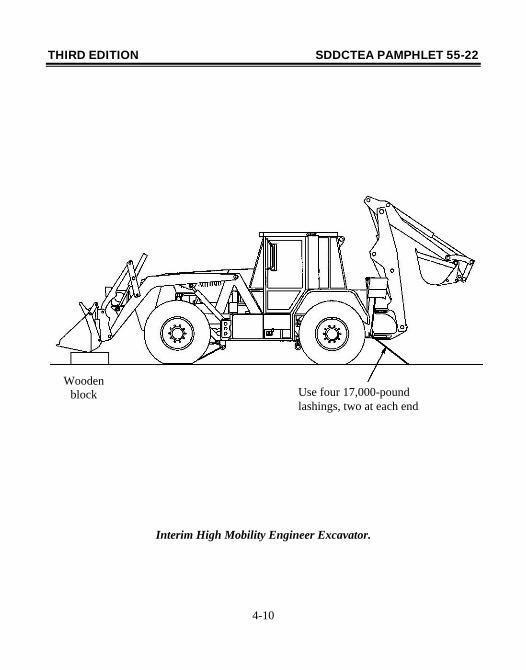
Interim High Mobility Engineer Excavator.
Wooden block Use four 17,000-pound
lashings, two at each end
THIRD EDITION SDDCTEA PAMPHLET 55-22
4-11
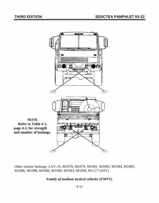
Other similar lashings: LAV-25, M1078, M1079, M1081, M1083, M1084, M1085, M1086, M1088, M1089, M1090, M1093, M1094, M1117 (ASV)
Family of medium tactical vehicles (FMTV).
NOTE Refer to Table 4-1,
page 4-2, for strength and number of lashings.
THIRD EDITION SDDCTEA PAMPHLET 55-22
4-12
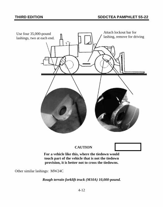
For a vehicle like this, where the tiedown would touch part of the vehicle that is not the tiedown provision, it is better not to cross the tiedowns.
Other similar lashings: MW24C
Rough terrain forklift truck (M10A) 10,000-pound.
CAUTION
Use four 35,000-pound lashings, two at each end.
Attach lockout bar for lashing, remove for driving
THIRD EDITION SDDCTEA PAMPHLET 55-22
4-13
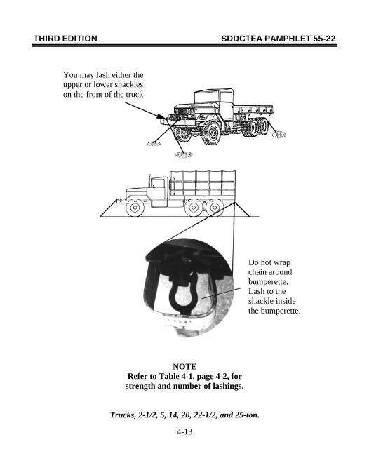
NOTE Refer to Table 4-1, page 4-2, for strength and number of lashings.
Trucks, 2-1/2, 5, 14, 20, 22-1/2, and 25-ton.
You may lash either the upper or lower shackles on the front of the truck
Do not wrap chain around bumperette. Lash to the shackle inside the bumperette.
THIRD EDITION SDDCTEA PAMPHLET 55-22
4-14
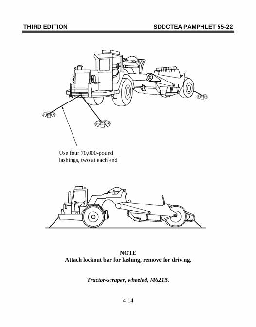
NOTE Attach lockout bar for lashing, remove for driving.
Tractor-scraper, wheeled, M621B.
Use four 70,000-pound lashings, two at each end
THIRD EDITION SDDCTEA PAMPHLET 55-22
4-15
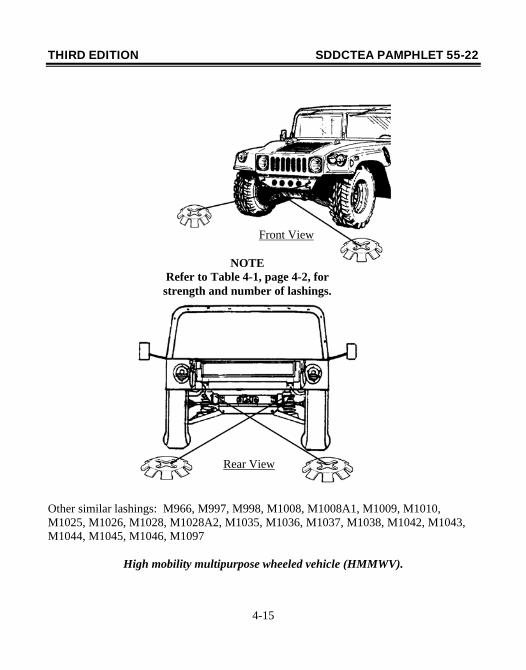
Other similar lashings: M966, M997, M998, M1008, M1008A1, M1009, M1010, M1025, M1026, M1028, M1028A2, M1035, M1036, M1037, M1038, M1042, M1043, M1044, M1045, M1046, M1097
High mobility multipurpose wheeled vehicle (HMMWV).
Front View
NOTE Refer to Table 4-1, page 4-2, for strength and number of lashings.
Rear View
THIRD EDITION SDDCTEA PAMPHLET 55-22
4-16
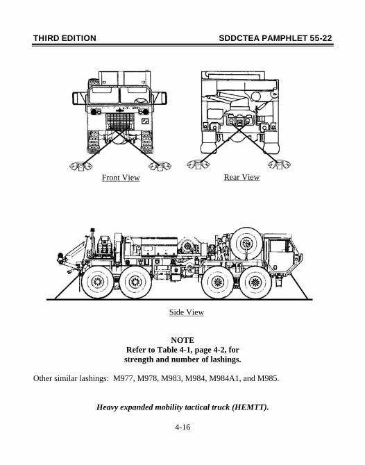
NOTE Refer to Table 4-1, page 4-2, for strength and number of lashings.
Other similar lashings: M977, M978, M983, M984, M984A1, and M985.
Heavy expanded mobility tactical truck (HEMTT).
Front View Rear View
Side View
THIRD EDITION SDDCTEA PAMPHLET 55-22
4-17
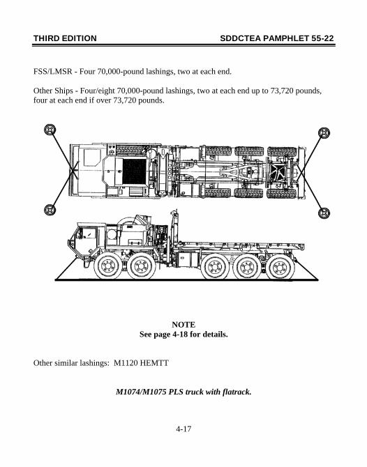
FSS/LMSR - Four 70,000-pound lashings, two at each end. Other Ships - Four/eight 70,000-pound lashings, two at each end up to 73,720 pounds, four at each end if over 73,720 pounds.
NOTE See page 4-18 for details.
Other similar lashings: M1120 HEMTT
M1074/M1075 PLS truck with flatrack.
THIRD EDITION SDDCTEA PAMPHLET 55-22
4-18
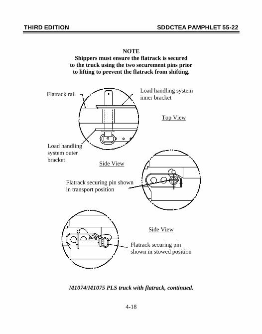
NOTE Shippers must ensure the flatrack is secured
to the truck using the two securement pins prior to lifting to prevent the flatrack from shifting.
M1074/M1075 PLS truck with flatrack, continued.
Load handling system inner bracket Flatrack rail
Load handling system outer bracket
Top View
Flatrack securing pin shown in transport position
Side View
Flatrack securing pin shown in stowed position
Side View
THIRD EDITION SDDCTEA PAMPHLET 55-22
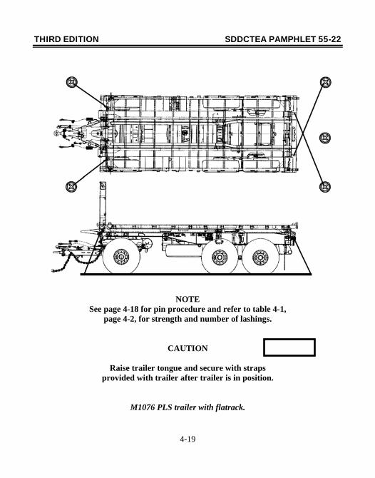
4-19
NOTE See page 4-18 for pin procedure and refer to table 4-1,
page 4-2, for strength and number of lashings.
CAUTION
Raise trailer tongue and secure with straps provided with trailer after trailer is in position.
M1076 PLS trailer with flatrack.
THIRD EDITION SDDCTEA PAMPHLET 55-22
4-20
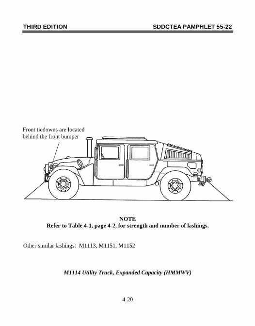
NOTE Refer to Table 4-1, page 4-2, for strength and number of lashings.
Other similar lashings: M1113, M1151, M1152
M1114 Utility Truck, Expanded Capacity (HMMWV)
Front tiedowns are located behind the front bumper
THIRD EDITION SDDCTEA PAMPHLET 55-22
4-21
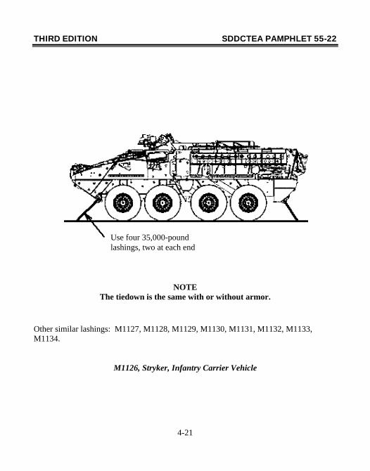
NOTE The tiedown is the same with or without armor.
Other similar lashings: M1127, M1128, M1129, M1130, M1131, M1132, M1133, M1134.
M1126, Stryker, Infantry Carrier Vehicle
Use four 35,000-pound lashings, two at each end
THIRD EDITION SDDCTEA PAMPHLET 55-22
4-22
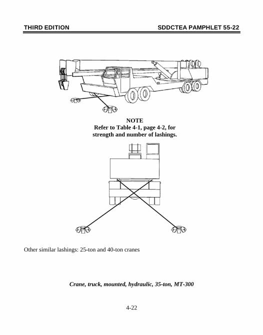
Other similar lashings: 25-ton and 40-ton cranes
Crane, truck, mounted, hydraulic, 35-ton, MT-300
NOTE Refer to Table 4-1, page 4-2, for strength and number of lashings.
THIRD EDITION SDDCTEA PAMPHLET 55-22
4-23
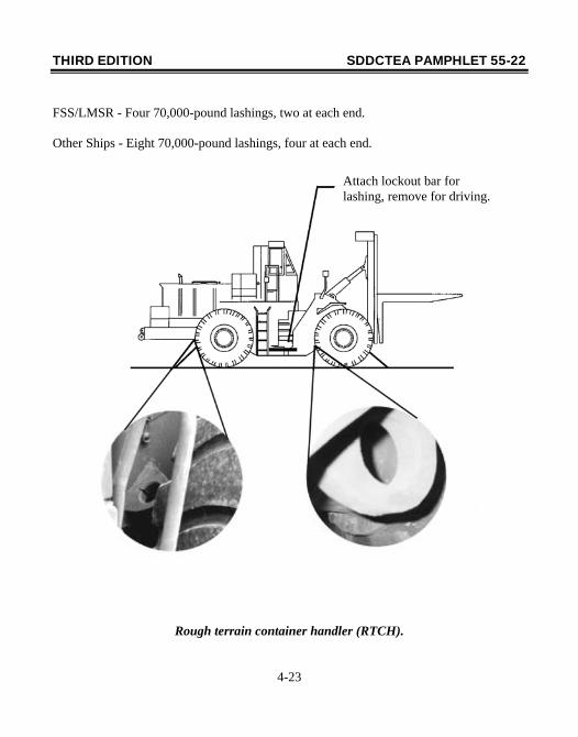
FSS/LMSR - Four 70,000-pound lashings, two at each end. Other Ships - Eight 70,000-pound lashings, four at each end.
Rough terrain container handler (RTCH).
Attach lockout bar for lashing, remove for driving.
THIRD EDITION SDDCTEA PAMPHLET 55-22
4-24
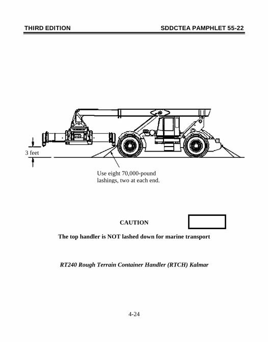
CAUTION
The top handler is NOT lashed down for marine transport
RT240 Rough Terrain Container Handler (RTCH) Kalmar
3 feet
Use eight 70,000-pound lashings, two at each end.
THIRD EDITION SDDCTEA PAMPHLET 55-22
4-25
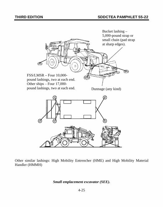
Other similar lashings: High Mobility Entrencher (HME) and High Mobility Material Handler (HMMH)
Small emplacement excavator (SEE).
Bucket lashing – 5,000-pound strap or small chain (pad strap at sharp edges).
FSS/LMSR – Four 10,000-pound lashings, two at each end. Other ships – Four 17,000-pound lashings, two at each end. Dunnage (any kind)
THIRD EDITION SDDCTEA PAMPHLET 55-22
4-26
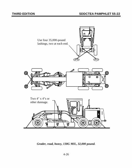
Grader, road, heavy, 130G MIL, 32,000 pound.
Use four 35,000-pound lashings, two at each end.
Two 4" x 4"s or other dunnage.
THIRD EDITION SDDCTEA PAMPHLET 55-22
4-27
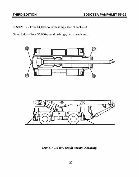
FSS/LMSR - Four 14,100-pound lashings, two at each end. Other Ships - Four 35,000-pound lashings, two at each end.
Crane, 7-1/2-ton, rough terrain, Koehring.
THIRD EDITION SDDCTEA PAMPHLET 55-22
5-1
Section V. Lashing Trailers This section provides guidance that applies to lashing trailers. Whenever possible, trailers should be towed aboard ship by, and stowed with, their prime movers as shown on page 5-10. Likewise, fifth-wheel semitrailers should always be coupled to their prime mover when stowed (see page 5-10). In both cases, the trailer and prime mover should be lashed as if they were separate, using Table 5-1 to determine the number and strength of the lashings required. This eliminates the need for blocking under the lunette or kingpin. When semitrailers are stowed without their prime mover, they must be placed on a stanchion. If the semitrailer is not loaded, the landing legs may be used instead of a stanchion. See page 5-5 for details. The stanchion should be centered under the kingpin. Place shoring under the landing legs, and lower them until they make contact with the shoring. Plywood cut slightly larger than the landing leg works well. If a trailer is loaded without its prime mover, a front support will be required if the trailer is loaded or used as a machinery platform such that equipment is in danger of tipping over (see page 5-16). If a front support is not required, plywood or similar blocking should be placed under the tow bar to prevent metal-to-metal contact with the deck as shown on page 5-6. The diagrams in this section typically show trailers that illustrate generic lashing procedures. For example, page 5-6 applies to all one and two-axle trailers. Table 5-2 lists trailers addressed in this handbook.
THIRD EDITION SDDCTEA PAMPHLET 55-22
5-2
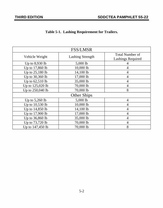
Table 5-1. Lashing Requirement for Trailers.
FSS/LMSR Vehicle Weight Lashing Strength Total Number of
Lashings Required Up to 8,930 lb 5,000 lb 4 Up to 17,860 lb 10,000 lb 4 Up to 25,180 lb 14,100 lb 4 Up to 30,360 lb 17,000 lb 4 Up to 62,510 lb 35,000 lb 4
Up to 125,020 lb 70,000 lb 4 Up to 250,040 lb 70,000 lb 8
Other Ships Up to 5,260 lb 5,000 lb 4 Up to 10,530 lb 10,000 lb 4 Up to 14,850 lb 14,100 lb 4 Up to 17,900 lb 17,000 lb 4 Up to 36,860 lb 35,000 lb 4 Up to 73,720 lb 70,000 lb 4
Up to 147,450 lb 70,000 lb 8
THIRD EDITION SDDCTEA PAMPHLET 55-22
5-3
Table 5-2. Trailers (Lashing).
Model Item Curb Gross Page Weight Weight (lb) (lb) M101A2 Trlr, Cargo, 3/4-ton 1,280 2,780 5-6 M105A2 Trlr, Cargo 1-1/2-ton 2,750 5,750 5-6 M107A1/A2 Trlr, Tank, Water, 1-1/2-ton 2,280 5,280 5-6 M116A2 Trlr, Cargo, 3/4-ton, 2 wheel 740 2,780 5-6 M118A1 Semitrlr, Stake, 6-ton 8,060 20,090 5-8 M119A1 Semitrlr, Van, Cargo, 6-ton 8,140 20,470 5-8 M127A1C Semitrlr, Stake, 12-ton 13,840 36,840 5-8 M128A1C Semitrlr, Van, Cargo, 12-ton 15,220 39,220 5-8 M129A2C Semitrlr, Van, Supply, 12-ton 15,400 39,400 5-8 M131A4 Semitrlr, Fuel, 5000 Gal. 12,900 36,165 5-9 M146 Semitrlr, Van, Shop, 6-ton 7,300 19,330 5-8 M149A2 Trlr, Tank, Water, 1-1/2-ton 2,730 6,062 5-6 M172A1 Semitrlr, Lowbed, 15-25-ton 16,600 16,600 5-10 M270A1 Semitrlr, Lowbed 17,500 17,500 5-10 M310 Trlr, Cable, Reel, 3-1/2-ton 2,950 9,950 5-6 M313 Semitrlr, Van, Expand, 6-ton 15,350 27,350 5-8 M332 Trlr, Ammo/Gen 2,875 5,875 5-6 Cargo, 1-1/2-ton M349A1 Semitrlr, Van, Refr, 7-1/2-ton 8,750 23,750 5-8 M373A2 Semitrlr, Van, Electronic, 6-ton 9,430 21,430 5-8 M416A1 Trlr, Cargo, 1/4-ton Semitrlr, 670 1,170 5-6 Van, Shop, 6-ton M447 Semitrlr, Van, Shop, 6-ton 13,080 25,080 5-8 M747 Semitrlr, Lowbed, HET, 60-ton 31,000 71,000 5-11 M777 Lightweight, 155mm Howitzer 9,400 9,400 5-12 M870A1 Trlr, Lowbed, 40-ton 16,500 96,500 5-10 M871 Semitrlr, Flatbed, 22-1/2-ton 15,900 60,900 5-13 M871A1 Semitrlr, Flatbed, 22-1/2-ton 15,630 61,630 5-13 M871A3 Semitrlr, Flatbed 17,600 45,000 5-13 M872 Semitrlr, Flatbed, 22-1/2-ton 17,400 84,600 5-13
THIRD EDITION SDDCTEA PAMPHLET 55-22
5-4
Table 5-2. Trailers (Lashing), continued.
Model Item Curb Gross Page Weight Weight (lb) (lb) M872A1 Semitrlr, Flatbed, 34-ton 19,240 86,440 5-13 M902 PATRIOT Launcher Trlr 35,000 58,500 5-14 M967 Semitrlr, fuel, 5000 Gal. 13,000 46,950 5-9 M967A1 Semitrlr, fuel, 5000 Gal. 13,000 46,950 5-9 M967A2 Semitrlr, fuel, 5000 Gal. 16,700 48,200 5-9 M969 Semitrlr, fuel, 5000 Gal. 15,000 48,950 5-9 M969A1 Semitrlr, fuel, 5000 Gal. 15,000 48,950 5-9 M969A2 Semitrlr, fuel, 5000 Gal. 16,500 50,450 5-9 M969A3 Semitrlr, fuel, 5000 Gal. 17,600 52,300 5-9 M970A1 Semitrlr, fuel, 5000 Gal. 15,210 15,210 5-9 M970A2 Semitrlr, fuel, 5000 Gal. 16,810 16,810 5-9 M989A1 Trlr, (HEMAT) 10,650 10,650 5-15 M1000 Semitrlr, HET 50,400 100,400 5-11 M1048 Trlr, MTSS, 6-1/2-ton 7,940 19,940 5-16 M1061 Trlr, Flatbed, 5-ton 5,850 15,000 5-6 M1061A1 Trlr, Gen. Purp, 5-ton 5,850 15,000 5-6 M1073 Trlr, Flatbed, 7-1/2-ton 6,640 20,255 5-6 M1082 FMTV 2-1/2-ton Trlr 6,860 11,500 5-6 M1095 FMTV 5-ton Trlr 9,202 20,000 5-6 M1098 Semitrlr, fuel, 5000 Gal. 16,810 55,810 5-9 M1112 400 Gallon Water Trlr 3,945 11,200 5-6 HP15T Trlr, Flatbed, Tilt Deck, 15-ton 8,000 38,000 5-6 PU-732/M Trlr, Power Unit N/A 6,080 5-6 ISO container on chassis 10,710 52,000 5-17
THIRD EDITION SDDCTEA PAMPHLET 55-22
5-5
NOTES
These are nominal dimensions and are in inches.
Lengths may vary depending on the height of the kingpin.
Semitrailer stanchions.
2 x 8
2 x 4
2 x 42 x 4
4 x 4
2 x 4
2 x 4
2 x 4
2 x 4
4 x 4
Center Under Kingpin
Place Against Back Side of Kingpin
THIRD EDITION SDDCTEA PAMPHLET 55-22
5-6
One- and two-axle trailers.
Do not allow tiedowns to pinch hoses or wires.
Run lashings under trailer tongue if necessary.
WARNING
Dunnage, 2" x 6" lumber or larger
NOTE Refer to Table 5-1, page 5-2, for strength and number of
lashings.
THIRD EDITION SDDCTEA PAMPHLET 55-22
5-7
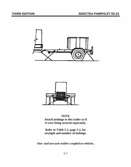
NOTE Attach lashings to the trailer as if it were being secured separately.
Refer to Table 5-1, page 5-2, for strength and number of lashings.
One- and two-axle trailers coupled to vehicles.
THIRD EDITION SDDCTEA PAMPHLET 55-22
5-8
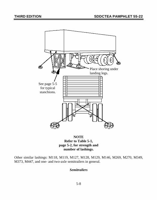
NOTE Refer to Table 5-1,
page 5-2, for strength and number of lashings.
Other similar lashings: M118, M119, M127, M128, M129, M146, M269, M270, M349, M373, M447, and one- and two-axle semitrailers in general.
Semitrailers
Place shoring under landing legs.
See page 5-5 for typical stanchions.
THIRD EDITION SDDCTEA PAMPHLET 55-22
5-9
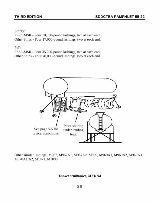
Empty: FSS/LMSR - Four 10,000-pound lashings, two at each end. Other Ships - Four 17,000-pound lashings, two at each end. Full: FSS/LMSR - Four 35,000-pound lashings, two at each end. Other Ships - Four 70,000-pound lashings, two at each end.
Other similar lashings: M967, M967A1, M967A2, M969, M969A1, M969A2, M969A3, M970A1/A2, M1071, M1098.
Tanker semitrailer, M131A4
See page 5-5 for typical stanchions.
Place shoring under landing
legs.
THIRD EDITION SDDCTEA PAMPHLET 55-22
5-10
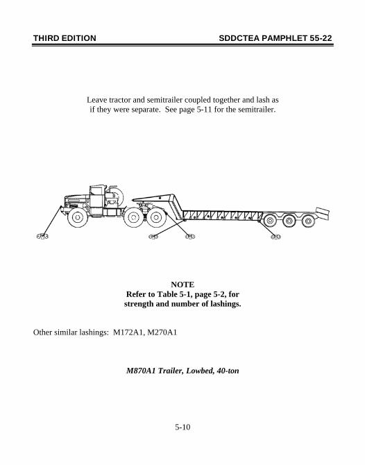
Leave tractor and semitrailer coupled together and lash as if they were separate. See page 5-11 for the semitrailer.
NOTE Refer to Table 5-1, page 5-2, for strength and number of lashings.
Other similar lashings: M172A1, M270A1
M870A1 Trailer, Lowbed, 40-ton
THIRD EDITION SDDCTEA PAMPHLET 55-22
5-11
NOTE Refer to Table 5-1,
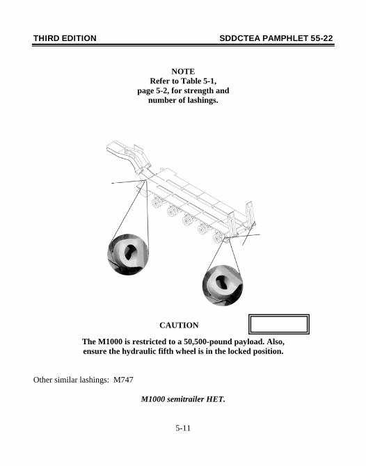
page 5-2, for strength and number of lashings.
The M1000 is restricted to a 50,500-pound payload. Also, ensure the hydraulic fifth wheel is in the locked position.
Other similar lashings: M747
M1000 semitrailer HET.
CAUTION
THIRD EDITION SDDCTEA PAMPHLET 55-22
5-12
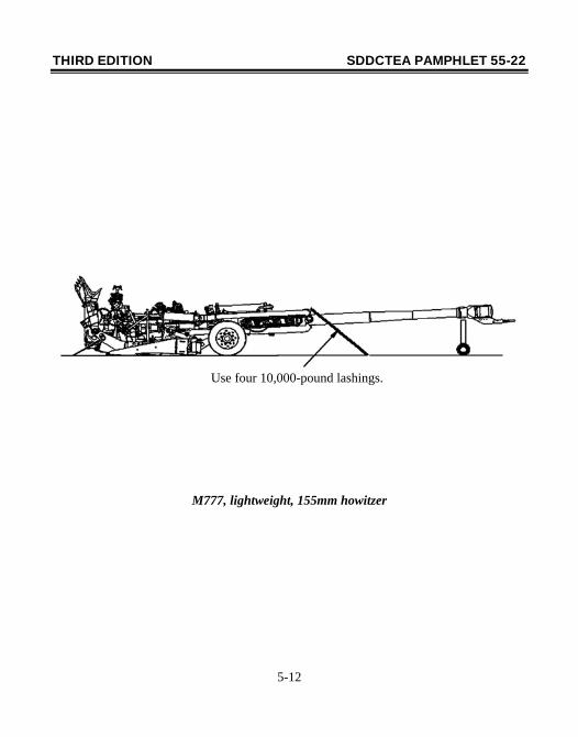
M777, lightweight, 155mm howitzer
Use four 10,000-pound lashings.
THIRD EDITION SDDCTEA PAMPHLET 55-22
5-13
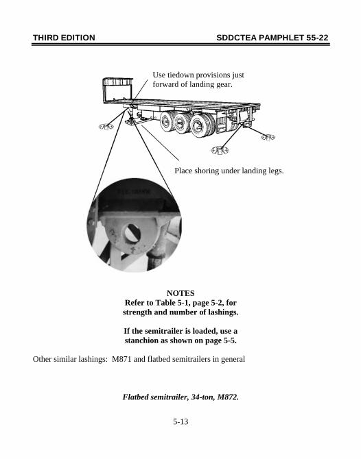
NOTES Refer to Table 5-1, page 5-2, for strength and number of lashings.
If the semitrailer is loaded, use a stanchion as shown on page 5-5.
Other similar lashings: M871 and flatbed semitrailers in general
Flatbed semitrailer, 34-ton, M872.
Use tiedown provisions just forward of landing gear.
Place shoring under landing legs.
THIRD EDITION SDDCTEA PAMPHLET 55-22
5-14
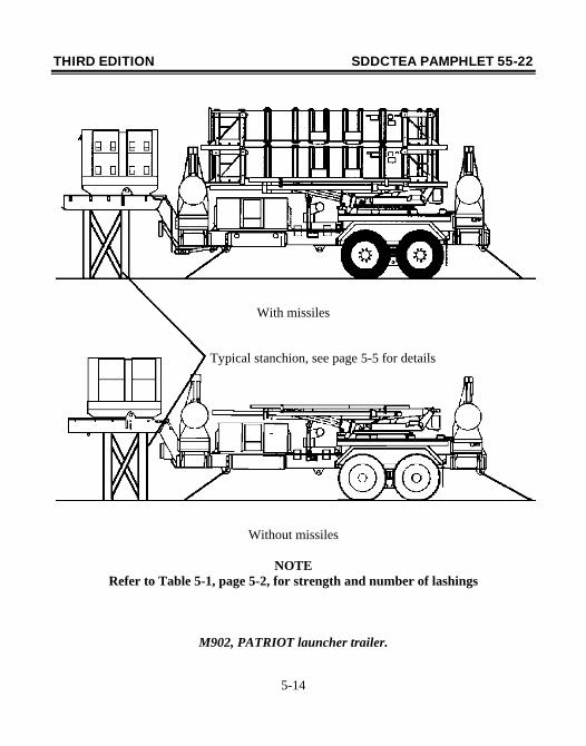
Without missiles
NOTE Refer to Table 5-1, page 5-2, for strength and number of lashings
M902, PATRIOT launcher trailer.
With missiles
Typical stanchion, see page 5-5 for details
THIRD EDITION SDDCTEA PAMPHLET 55-22
5-15
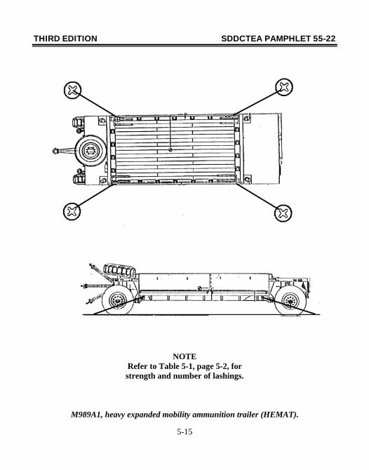
NOTE Refer to Table 5-1, page 5-2, for strength and number of lashings.
M989A1, heavy expanded mobility ammunition trailer (HEMAT).
THIRD EDITION SDDCTEA PAMPHLET 55-22
5-16
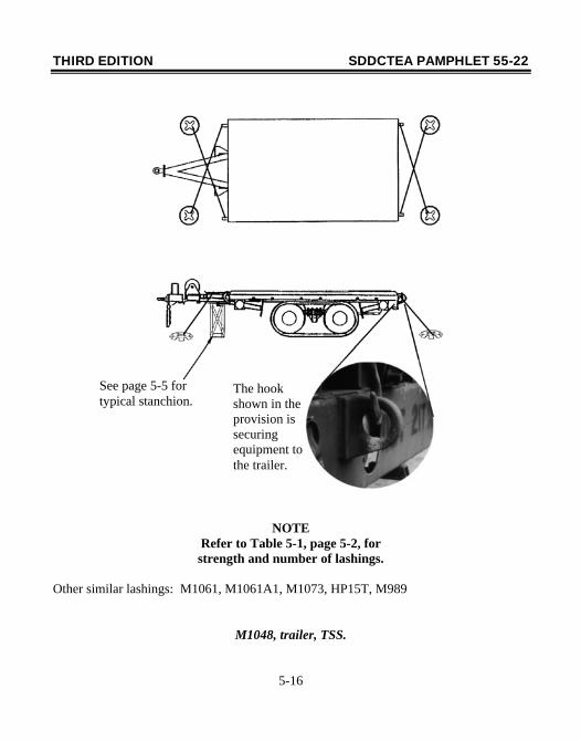
NOTE Refer to Table 5-1, page 5-2, for strength and number of lashings.
Other similar lashings: M1061, M1061A1, M1073, HP15T, M989
M1048, trailer, TSS.
See page 5-5 for typical stanchion.
The hook shown in the provision is securing equipment to the trailer.
THIRD EDITION SDDCTEA PAMPHLET 55-22
5-17
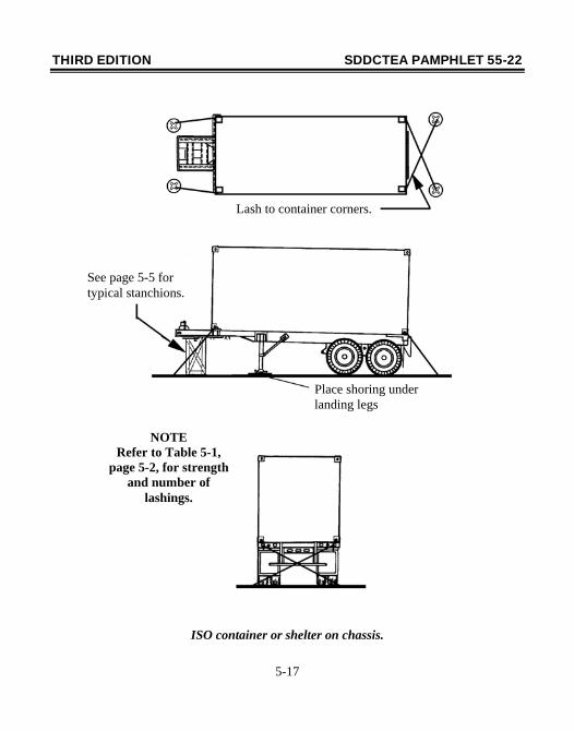
ISO container or shelter on chassis.
Lash to container corners.
See page 5-5 for typical stanchions.
Place shoring under landing legs
NOTE Refer to Table 5-1,
page 5-2, for strength and number of
lashings.
THIRD EDITION SDDCTEA PAMPHLET 55-22
6-1
Section VI. Lashing Tracked Vehicles This section provides guidance on lashing tracked vehicles. Throughout this section, lashing requirements are based on the universal four-lashing pattern - two fore and two aft. However, eight or more lashings may be required, depending on the vehicle weight and available lashing strength. For example, an M1 tank combat loaded to 137,360 pounds would require eight 70,000-pound lashings or sixteen 35,000-pound lashings. Table 6-1 should be used to determine the actual number of lashings required for a given vehicle weight. Note that in some cases, diagrams are shown for unique vehicles and in others for vehicles that illustrate generic lashing procedures. For example, page 6-5 illustrates the D7 Caterpillar tractor with blade and ripper so that shoring requirements are not overlooked. Page 6-10, on the other hand, is a generic medium tracked vehicle representing the M113 family and similar vehicles. This approach helps reduce the size and complexity of the pamphlet. Note that tracked vehicles are typically classified as high density loads. Therefore, they are usually stowed below the weatherdeck to help optimize the ship’s trim and stability by keeping the ship's overall center of gravity as low as possible (combats the tendency to roll). This will likely ensure that these vehicles will not experience the full effect of the load factors described in Appendix A. Based on these observations, Table 6-1 is considered to be conservative to the extent that lashing requirements shown therein should not be exceeded. Table 6-2 lists the tracked vehicles included in this handbook.
THIRD EDITION SDDCTEA PAMPHLET 55-22
6-2
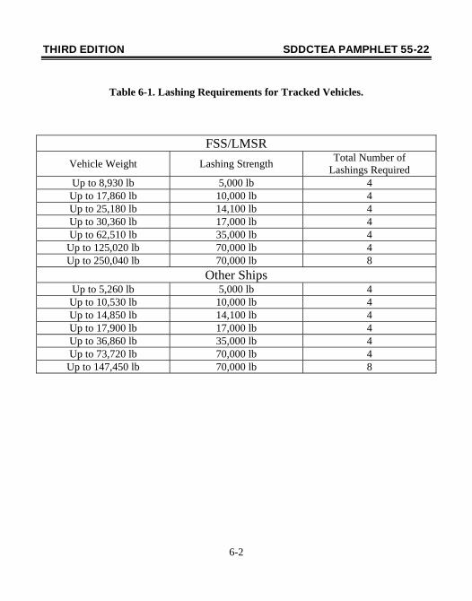
Table 6-1. Lashing Requirements for Tracked Vehicles.
FSS/LMSR Vehicle Weight Lashing Strength Total Number of
Lashings Required Up to 8,930 lb 5,000 lb 4 Up to 17,860 lb 10,000 lb 4 Up to 25,180 lb 14,100 lb 4 Up to 30,360 lb 17,000 lb 4 Up to 62,510 lb 35,000 lb 4
Up to 125,020 lb 70,000 lb 4 Up to 250,040 lb 70,000 lb 8
Other Ships Up to 5,260 lb 5,000 lb 4 Up to 10,530 lb 10,000 lb 4 Up to 14,850 lb 14,100 lb 4 Up to 17,900 lb 17,000 lb 4 Up to 36,860 lb 35,000 lb 4 Up to 73,720 lb 70,000 lb 4
Up to 147,450 lb 70,000 lb 8
THIRD EDITION SDDCTEA PAMPHLET 55-22
6-3
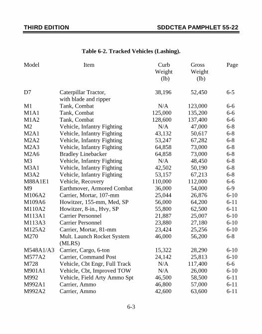
Table 6-2. Tracked Vehicles (Lashing).
Model Item Curb Gross Page Weight Weight (lb) (lb)
D7 Caterpillar Tractor, 38,196 52,450 6-5 with blade and ripper M1 Tank, Combat N/A 123,000 6-6 M1A1 Tank, Combat 125,000 135,200 6-6 M1A2 Tank, Combat 128,600 137,400 6-6 M2 Vehicle, Infantry Fighting N/A 47,000 6-8 M2A1 Vehicle, Infantry Fighting 43,132 50,617 6-8 M2A2 Vehicle, Infantry Fighting 53,247 67,282 6-8 M2A3 Vehicle, Infantry Fighting 64,858 73,000 6-8 M2A6 Bradley Linebacker 64,858 73,000 6-8 M3 Vehicle, Infantry Fighting N/A 48,450 6-8 M3A1 Vehicle, Infantry Fighting 42,502 50,190 6-8 M3A2 Vehicle, Infantry Fighting 53,157 67,213 6-8 M88A1E1 Vehicle, Recovery 110,000 112,000 6-6 M9 Earthmover, Armored Combat 36,000 54,000 6-9 M106A2 Carrier, Mortar, 107-mm 25,044 26,876 6-10 M109A6 Howitzer, 155-mm, Med, SP 56,000 64,200 6-11 M110A2 Howitzer, 8-in., Hvy, SP 55,800 62,500 6-11 M113A1 Carrier Personnel 21,887 25,007 6-10 M113A3 Carrier Personnel 23,880 27,180 6-10 M125A2 Carrier, Mortar, 81-mm 23,424 25,256 6-10 M270 Mult. Launch Rocket System 46,000 56,200 6-8 (MLRS) M548A1/A3 Carrier, Cargo, 6-ton 15,322 28,290 6-10 M577A2 Carrier, Command Post 24,142 25,813 6-10 M728 Vehicle, Cbt Engr, Full Track N/A 117,400 6-6 M901A1 Vehicle, Cbt, Improved TOW N/A 26,000 6-10 M992 Vehicle, Field Arty Ammo Spt 46,500 58,500 6-11 M992A1 Carrier, Ammo 46,800 57,000 6-11 M992A2 Carrier, Ammo 42,600 63,600 6-11
THIRD EDITION SDDCTEA PAMPHLET 55-22
6-4
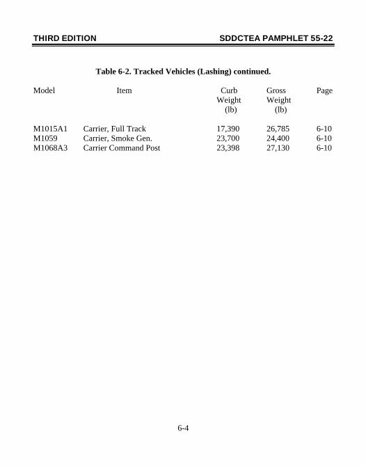
Table 6-2. Tracked Vehicles (Lashing) continued.
Model Item Curb Gross Page Weight Weight (lb) (lb) M1015A1 Carrier, Full Track 17,390 26,785 6-10 M1059 Carrier, Smoke Gen. 23,700 24,400 6-10 M1068A3 Carrier Command Post 23,398 27,130 6-10
THIRD EDITION SDDCTEA PAMPHLET 55-22
6-5
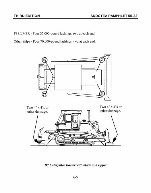
FSS/LMSR - Four 35,000-pound lashings, two at each end. Other Ships - Four 70,000-pound lashings, two at each end.
D7 Caterpillar tractor with blade and ripper
Two 4" x 4"s or other dunnage.
Two 4" x 4"s or other dunnage.
THIRD EDITION SDDCTEA PAMPHLET 55-22
6-6
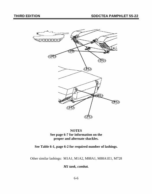
NOTES See page 6-7 for information on the
proper and alternate shackles.
See Table 6-1, page 6-2 for required number of lashings.
Other similar lashings: M1A1, M1A2, M88A1, M88A1E1, M728
M1 tank, combat.
THIRD EDITION SDDCTEA PAMPHLET 55-22
6-7
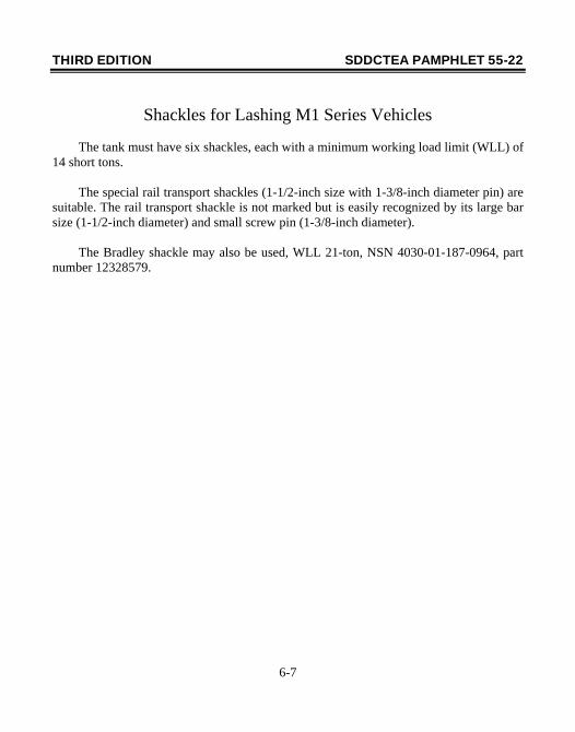
Shackles for Lashing M1 Series Vehicles The tank must have six shackles, each with a minimum working load limit (WLL) of 14 short tons. The special rail transport shackles (1-1/2-inch size with 1-3/8-inch diameter pin) are suitable. The rail transport shackle is not marked but is easily recognized by its large bar size (1-1/2-inch diameter) and small screw pin (1-3/8-inch diameter). The Bradley shackle may also be used, WLL 21-ton, NSN 4030-01-187-0964, part number 12328579.
THIRD EDITION SDDCTEA PAMPHLET 55-22
6-8
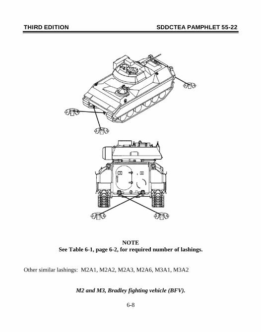
NOTE See Table 6-1, page 6-2, for required number of lashings.
Other similar lashings: M2A1, M2A2, M2A3, M2A6, M3A1, M3A2
M2 and M3, Bradley fighting vehicle (BFV).
THIRD EDITION SDDCTEA PAMPHLET 55-22
6-9
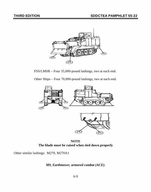
NOTE
The blade must be raised when tied down properly
Other similar lashings: M270, M270A1
M9, Earthmover, armored combat (ACE).
FSS/LMSR – Four 35,000-pound lashings, two at each end. Other Ships – Four 70,000-pound lashings, two at each end.
THIRD EDITION SDDCTEA PAMPHLET 55-22
6-10
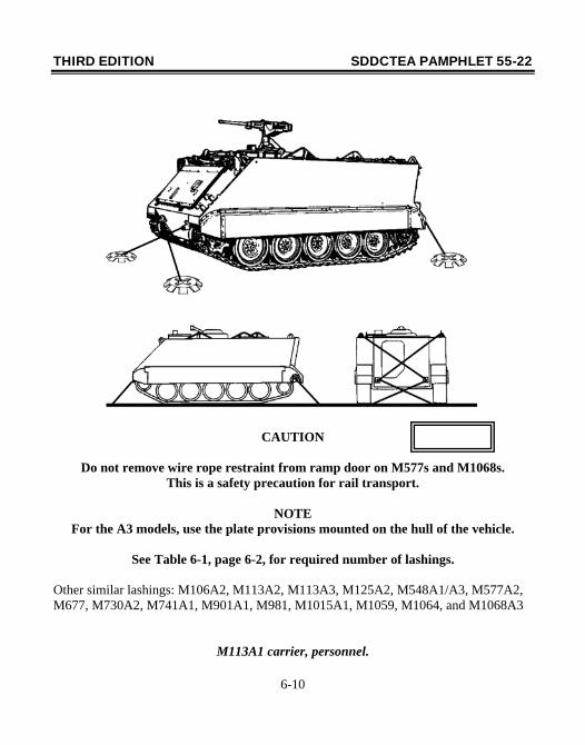
CAUTION
Do not remove wire rope restraint from ramp door on M577s and M1068s. This is a safety precaution for rail transport.
NOTE
For the A3 models, use the plate provisions mounted on the hull of the vehicle.
See Table 6-1, page 6-2, for required number of lashings.
Other similar lashings: M106A2, M113A2, M113A3, M125A2, M548A1/A3, M577A2, M677, M730A2, M741A1, M901A1, M981, M1015A1, M1059, M1064, and M1068A3
M113A1 carrier, personnel.
THIRD EDITION SDDCTEA PAMPHLET 55-22
6-11
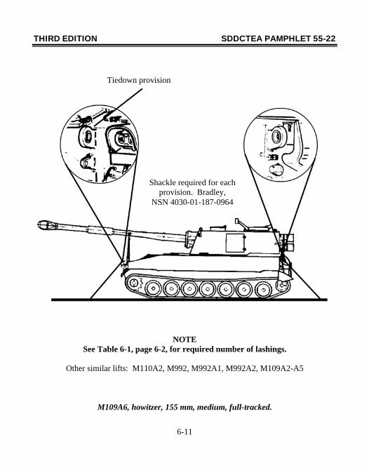
NOTE See Table 6-1, page 6-2, for required number of lashings.
Other similar lifts: M110A2, M992, M992A1, M992A2, M109A2-A5
M109A6, howitzer, 155 mm, medium, full-tracked.
Tiedown provision
Shackle required for each provision. Bradley,
NSN 4030-01-187-0964
THIRD EDITION SDDCTEA PAMPHLET 55-22
7-1
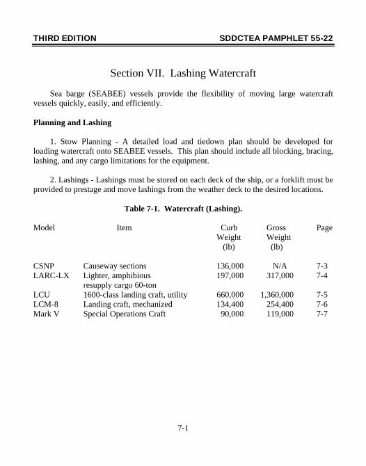
Section VII. Lashing Watercraft
Sea barge (SEABEE) vessels provide the flexibility of moving large watercraft vessels quickly, easily, and efficiently. Planning and Lashing 1. Stow Planning - A detailed load and tiedown plan should be developed for loading watercraft onto SEABEE vessels. This plan should include all blocking, bracing, lashing, and any cargo limitations for the equipment. 2. Lashings - Lashings must be stored on each deck of the ship, or a forklift must be provided to prestage and move lashings from the weather deck to the desired locations.
Table 7-1. Watercraft (Lashing).
Model Item Curb Gross Page Weight Weight (lb) (lb) CSNP Causeway sections 136,000 N/A 7-3 LARC-LX Lighter, amphibious 197,000 317,000 7-4 resupply cargo 60-ton LCU 1600-class landing craft, utility 660,000 1,360,000 7-5 LCM-8 Landing craft, mechanized 134,400 254,400 7-6 Mark V Special Operations Craft 90,000 119,000 7-7
THIRD EDITION SDDCTEA PAMPHLET 55-22
7-2
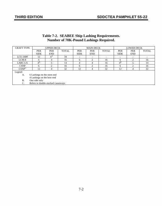
Table 7-2. SEABEE Ship Lashing Requirements.
Number of 70K-Pound Lashings Required.
CRAFT TYPE UPPER DECK MAIN DECK LOWER DECK PER SIDE
PER END
TOTAL PER SIDE
PER END
TOTAL PER SIDE
PER END
TOTAL
LCU-1600 12 6A 34 - - - - - - LCM-8 6 4 16 6 2 16 6 2 16
LARC-LX 4B 5 14 4 4 16 4B 5 14 CSNP 6 2 16 6 2 16 6 2 16 CSNPC 12 4 32 12 4 32 12 4 32
Legend: A. 6 Lashings on the stern end
4 Lashings on the bow end B. One side only C. Refers to double-stacked causeways
THIRD EDITION SDDCTEA PAMPHLET 55-22
7-3
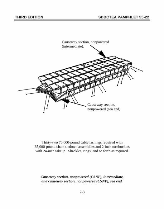
Thirty-two 70,000-pound cable lashings required with 35,000-pound chain tiedown assemblies and 2-inch turnbuckles with 24-inch takeup. Shackles, rings, and so forth as required.
Causeway section, nonpowered (CSNP), intermediate, and causeway section, nonpowered (CSNP), sea end.
Causeway section, nonpowered (intermediate).
Causeway section, nonpowered (sea end).
THIRD EDITION SDDCTEA PAMPHLET 55-22
7-4
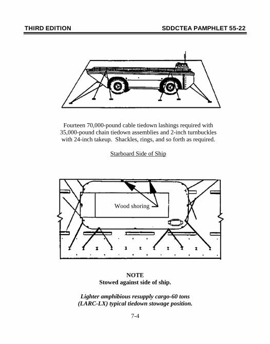
NOTE Stowed against side of ship.
Lighter amphibious resupply cargo-60 tons
(LARC-LX) typical tiedown stowage position.
Fourteen 70,000-pound cable tiedown lashings required with 35,000-pound chain tiedown assemblies and 2-inch turnbuckles with 24-inch takeup. Shackles, rings, and so forth as required.
Starboard Side of Ship
Wood shoring
THIRD EDITION SDDCTEA PAMPHLET 55-22
7-5
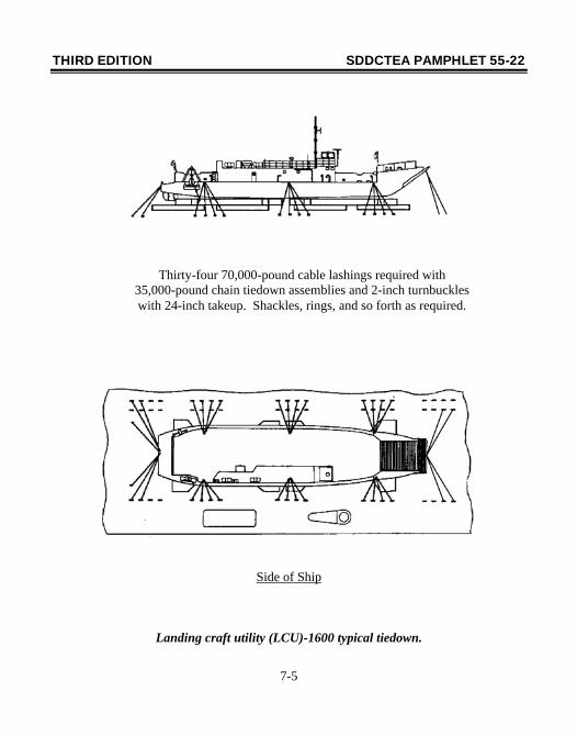
Side of Ship
Landing craft utility (LCU)-1600 typical tiedown.
Thirty-four 70,000-pound cable lashings required with 35,000-pound chain tiedown assemblies and 2-inch turnbuckles with 24-inch takeup. Shackles, rings, and so forth as required.
THIRD EDITION SDDCTEA PAMPHLET 55-22
7-6
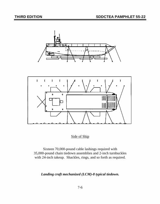
Side of Ship
Sixteen 70,000-pound cable lashings required with 35,000-pound chain tiedown assemblies and 2-inch turnbuckles with 24-inch takeup. Shackles, rings, and so forth as required.
Landing craft mechanized (LCM)-8 typical tiedown.
THIRD EDITION SDDCTEA PAMPHLET 55-22
7-7
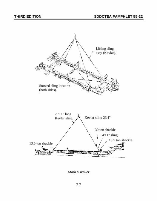
Mark V trailer
Lifting sling assy (Kevlar).
Stowed sling location (both sides).
13.5 ton shackle 4'11" sling
30 ton shackle
Kevlar sling 23'4"29'11" long Kevlar sling
13.5 ton shackle
THIRD EDITION SDDCTEA PAMPHLET 55-22
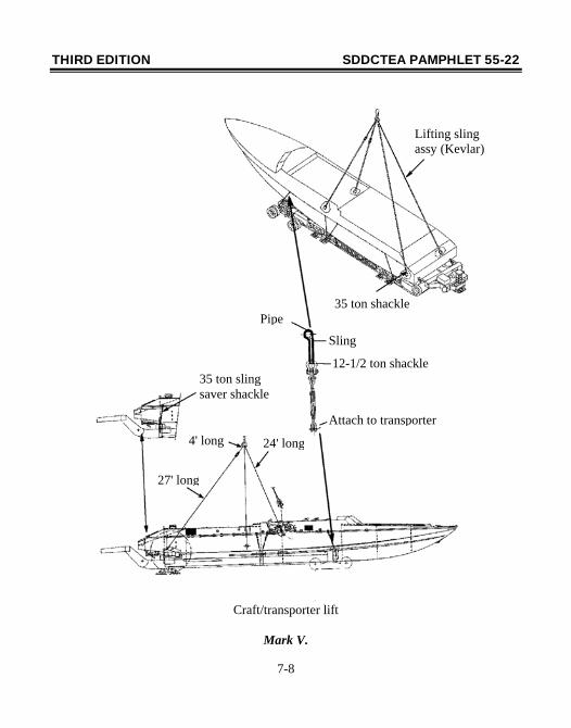
7-8
Craft/transporter lift
Mark V.
Lifting sling assy (Kevlar)
35 ton shacklePipe
Sling
12-1/2 ton shackle
Attach to transporter
35 ton sling saver shackle
4' long
27' long
24' long
THIRD EDITION SDDCTEA PAMPHLET 55-22
7-9
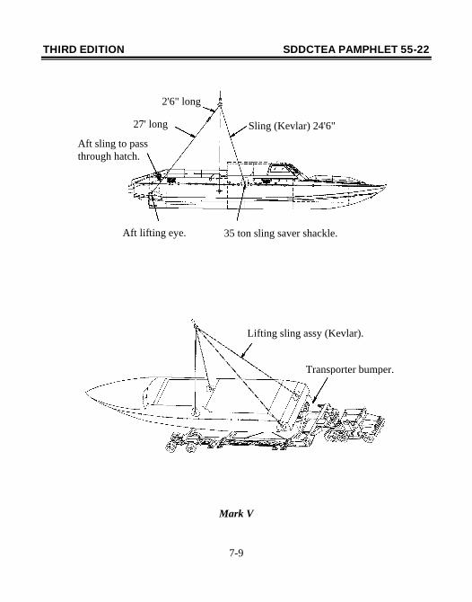
Mark V
2'6" long
27' long Sling (Kevlar) 24'6"
Aft sling to pass through hatch.
Aft lifting eye. 35 ton sling saver shackle.
Lifting sling assy (Kevlar).
Transporter bumper.
THIRD EDITION SDDCTEA PAMPHLET 55-22
7-10
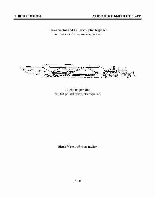
Leave tractor and trailer coupled together and lash as if they were separate.
12 chains per side 70,000-pound restraints required.
Mark V restraint on trailer
THIRD EDITION SDDCTEA PAMPHLET 55-22
A-1
Appendix A
Cargo Restraint Criteria for Marine Transport: Development and Implementation
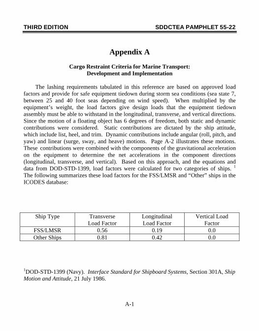
The lashing requirements tabulated in this reference are based on approved load factors and provide for safe equipment tiedown during storm sea conditions (sea state 7, between 25 and 40 foot seas depending on wind speed). When multiplied by the equipment’s weight, the load factors give design loads that the equipment tiedown assembly must be able to withstand in the longitudinal, transverse, and vertical directions. Since the motion of a floating object has 6 degrees of freedom, both static and dynamic contributions were considered. Static contributions are dictated by the ship attitude, which include list, heel, and trim. Dynamic contributions include angular (roll, pitch, and yaw) and linear (surge, sway, and heave) motions. Page A-2 illustrates these motions. These contributions were combined with the components of the gravitational acceleration on the equipment to determine the net accelerations in the component directions (longitudinal, transverse, and vertical). Based on this approach, and the equations and data from DOD-STD-1399, load factors were calculated for two categories of ships. 1 The following summarizes these load factors for the FSS/LMSR and “Other” ships in the ICODES database:
Ship Type Transverse Load Factor
Longitudinal Load Factor
Vertical Load Factor
FSS/LMSR 0.56 0.19 0.0 Other Ships 0.81 0.42 0.0
1DOD-STD-1399 (Navy). Interface Standard for Shipboard Systems, Section 301A, Ship Motion and Attitude, 21 July 1986.
THIRD EDITION SDDCTEA PAMPHLET 55-22
A-2
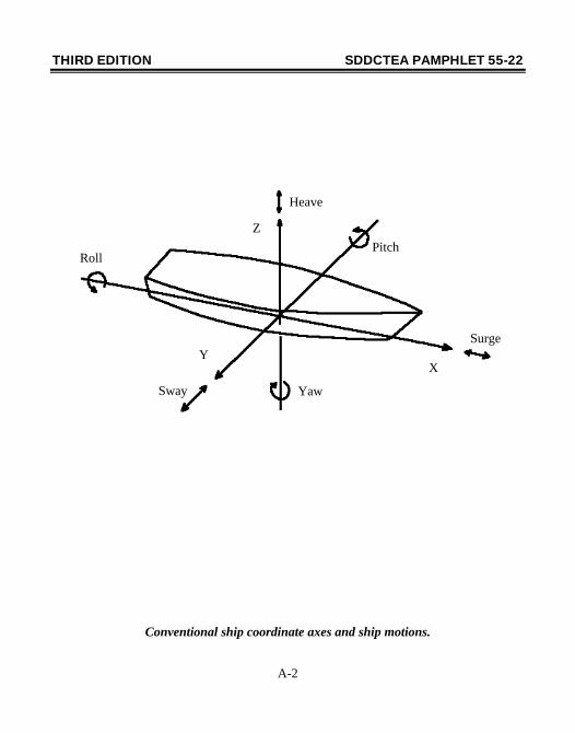
Conventional ship coordinate axes and ship motions.
Z
XY
Pitch
Heave
Surge
YawSway
Roll
THIRD EDITION SDDCTEA PAMPHLET 55-22
A-3
NOTES 1. Ship data was furnished by MSC and MARAD. 2. Load factors are based on sea state 7 conditions (between 29 and 40 ft seas). 3. Load factors were calculated IAW DOD-STD-1399, Section 301A, Ship Motion and Attitude. 4. Load factors were calculated at farthest stowage location from ship’s center of gravity. 5. Load factors were based on a partially loaded ship with respect to the metacentric height. Once developed, the load factors on page A-1 became the foundation for the lashing requirements tabulated in this reference. During a decision briefing to MSC and MARAD, the following load factor implementation plan was agreed to by consensus2:
1. Apply load factors simultaneously versus independently to account for each factor peaking at the same time. 2. Assume friction forces between equipment and deck are negligible (water and lubricant on deck). 3. Assume a 25° angle between deck and lashing. 4. Assume equipment center of gravity is in the geometric center. 5. Base lashing requirements on known lashing capacities and corresponding equipment weight ranges. 2MTMCTEA Decision Briefing at Washington Navy Yard, 12 Apr 94, subject: Implementation of Load Factors for Cargo Restraint During Marine Transport.
THIRD EDITION SDDCTEA PAMPHLET 55-22
A-4
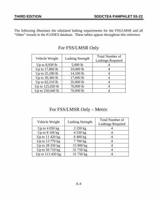
The following illustrates the tabulated lashing requirements for the FSS/LMSR and all "Other" vessels in the ICODES database. These tables appear throughout this reference.
For FSS/LMSR Only
For FSS/LMSR Only – Metric
Vehicle Weight Lashing Strength Total Number of Lashings Required
Up to 4 050 kg 2 250 kg 4 Up to 8 100 kg 4 550 kg 4 Up to 11 420 kg 6 400 kg 4 Up to 13 770 kg 7 700 kg 4 Up to 28 350 kg 15 900 kg 4 Up to 56 710 kg 31 750 kg 4
Up to 113 420 kg 31 750 kg 4
Vehicle Weight Lashing Strength Total Number of Lashings Required
Up to 8,930 lb 5,000 lb 4 Up to 17,860 lb 10,000 lb 4 Up to 25,180 lb 14,100 lb 4 Up to 30,360 lb 17,000 lb 4 Up to 62,510 lb 35,000 lb 4 Up to 125,020 lb 70,000 lb 4 Up to 250,040 lb 70,000 lb 4
THIRD EDITION SDDCTEA PAMPHLET 55-22
A-5
For Other Ships Only
Vehicle Weight Lashing Strength Total Number of Lashings Required
Up to 5,260 lb 5,000 lb 4 Up to 10,530 lb 10,000 lb 4 Up to 14,850 lb 14,100 lb 4 Up to 17,900 lb 17,000 lb 4 Up to 36,860 lb 35,000 lb 4 Up to 73,720 lb 70,000 lb 4 Up to 147,450 lb 70,000 lb 4
For Other Ships Only – Metric
Vehicle Weight Lashing Strength Total Number of Lashings Required
Up to 2 390 kg 2 250 kg 4 Up to 4 780 kg 4 550 kg 4 Up to 6 740 kg 6 400 kg 4 Up to 8 120 kg 7 700 kg 4
Up to 16 720 kg 15 900 kg 4 Up to 33 440 kg 31 750 kg 4 Up to 66 880 kg 31 750 kg 4
Note: “Other” ships are all ships except FSS and LMSR.
THIRD EDITION SDDCTEA PAMPHLET 55-22
B-1
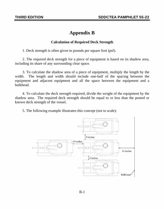
Appendix B
Calculation of Required Deck Strength 1. Deck strength is often given in pounds per square foot (psf). 2. The required deck strength for a piece of equipment is based on its shadow area, including its share of any surrounding clear space. 3. To calculate the shadow area of a piece of equipment, multiply the length by the width. The length and width should include one-half of the spacing between the equipment and adjacent equipment and all the space between the equipment and a bulkhead. 4. To calculate the deck strength required, divide the weight of the equipment by the shadow area. The required deck strength should be equal to or less than the posted or known deck strength of the vessel. 5. The following example illustrates this concept (not to scale):
THIRD EDITION SDDCTEA PAMPHLET 55-22
B-2
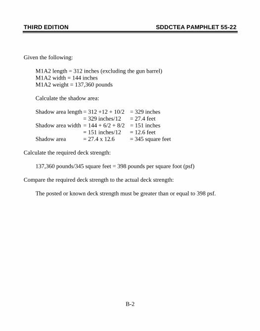
Given the following: M1A2 length = 312 inches (excluding the gun barrel) M1A2 width = 144 inches M1A2 weight = 137,360 pounds Calculate the shadow area: Shadow area length = 312 +12 + 10/2 = 329 inches = 329 inches/12 = 27.4 feet Shadow area width = 144 + 6/2 + 8/2 = 151 inches = 151 inches/12 = 12.6 feet Shadow area = 27.4 x 12.6 = 345 square feet Calculate the required deck strength: 137,360 pounds/345 square feet = 398 pounds per square foot (psf) Compare the required deck strength to the actual deck strength: The posted or known deck strength must be greater than or equal to 398 psf.
THIRD EDITION SDDCTEA PAMPHLET 55-22
C-1
Appendix C
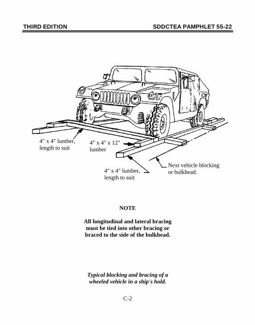
Recommended Blocking and Bracing Procedures Under normal circumstances, blocking and bracing is not required for marine transport. Military vehicles, shelters, and trailers are equipped with tiedown provisions that are more than adequate to provide restraint under the worst sea conditions. An exception to this applies when lumber is placed under steel tracks to prevent metal-to-metal contact. However, the following circumstances could dictate that blocking and bracing are required to secure the equipment. 1. Deck fittings do not have adequate strength to restrain the equipment. In this case, blocking and bracing may be required to supplement the restraint provided by the lashings. 2. The ship is not equipped with deck fittings to accommodate lashing gear. When this occurs, blocking and bracing will be the only means to achieve restraint requirements. 3. The number and location of the deck fittings do not adequately accommodate standard lashing procedures. Again, blocking and bracing may be necessary to achieve the required restraint. 4. The ship has adequate deck fittings but is not equipped with lashing gear. When the above situations arise, blocking may be the only means to secure the cargo. If this is the case, proper procedures are critical. Wheels must be chocked on all four sides and braced to the ship's bulkhead or each other as shown on page C-2. Failure to brace to the bulkhead defeats the purpose of the blocking since it leaves the entire assembly (vehicle and surrounding lumber) free to shift during transit.
THIRD EDITION SDDCTEA PAMPHLET 55-22
C-2
NOTE
All longitudinal and lateral bracing must be tied into other bracing or braced to the side of the bulkhead.
Typical blocking and bracing of a wheeled vehicle in a ship's hold.
4" x 4" lumber, length to suit
4" x 4" x 12" lumber
4" x 4" lumber, length to suit
Next vehicle blocking or bulkhead.
THIRD EDITION SDDCTEA PAMPHLET 55-22
C-3
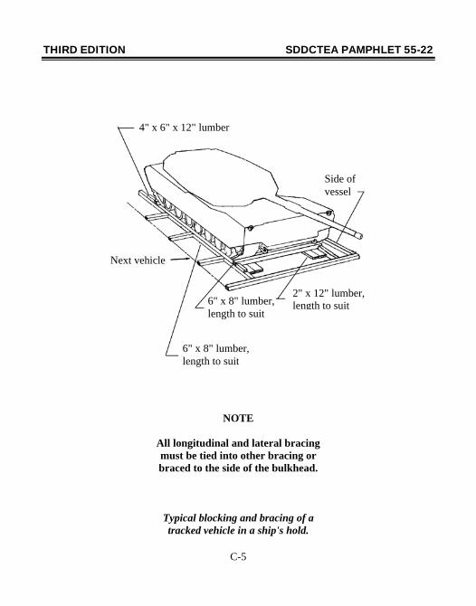
Whenever possible, trailers and semitrailers should remain attached to their respective prime movers and blocked and braced in accordance with the wheeled vehicle diagrams. This helps simplify the blocking and bracing requirements by eliminating the need for stanchions, front supports, and so forth. Page C-4 applies to trailers and semitrailers separated from their prime movers. For tracked vehicles, refer to page C-5. In addition to the blocking and bracing shown, lumber may be required under the tracks to prevent metal-to-metal contact with the deck.
THIRD EDITION SDDCTEA PAMPHLET 55-22
C-4
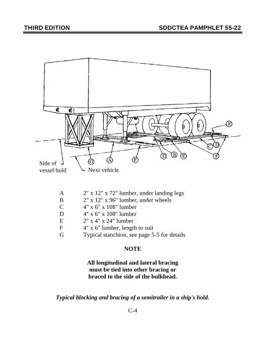
A 2" x 12" x 72" lumber, under landing legs B 2" x 12" x 96" lumber, under wheels C 4" x 6" x 108" lumber D 4" x 6" x 108" lumber E 2" x 4" x 24" lumber F 4" x 6" lumber, length to suit G Typical stanchion, see page 5-5 for details
NOTE
All longitudinal and lateral bracing must be tied into other bracing or braced to the side of the bulkhead.
Typical blocking and bracing of a semitrailer in a ship's hold.
Next vehicleSide of vessel hold
THIRD EDITION SDDCTEA PAMPHLET 55-22
C-5
NOTE
All longitudinal and lateral bracing must be tied into other bracing or braced to the side of the bulkhead.
Typical blocking and bracing of a tracked vehicle in a ship's hold.
4" x 6" x 12" lumber
6" x 8" lumber, length to suit
2" x 12" lumber, length to suit6" x 8" lumber,
length to suit
Next vehicle
Side of vessel