thin bonded concrete overlay with fast track concrete · thin bonded concrete overlay with fast...
TRANSCRIPT
THIN BONDED CONCRETE OVERLAY
WITH FAST TRACK CONCRETE
Final 'Report for lowa DOT Project HR-531
Federal Highway Administration Project DTFH 71 -86-502-IA-22
November 1990
Highway Division
f lowa Department f Transportation 0

Final Report for
Iowa Department of Transportation Project HR-531
Thin Bonded Concrete Overlay With
Fast Track Concrete
by Georqe Calvert
Iowa Department of Transportation (Retired)
and
0. J. (John) Lane Jr., P.E. Testing Engineer 515-239-1237
Iowa Department of Transportati.on Ames, Iowa 50010
and
Chris Anderson 515-239-1392
Office of Materials Highway Division
Iowa Department of Transportation Ames, Iowa 50010
November 1990

TABLE OF CONTENTS
Page
Abstract ............................................ 1
........................................ Introduction 2
........................................... Objective 3
Project Description ................................. 4
Materials ......................................... 5
Construction ...................................... 6
Test Data ........................................... 13
Evaluation at One Year .............................. 15
Tests Conducted at One Year ......................... 16
Summary ............................................. 21
Conclusions ..................................... 23
Appendix - Figures of Sketches and Graphs ........... 24
DISCLAIMER
The contents of this report reflect the views of the authors and do not necessarily reflect the official views of the Iowa Department of Transportation . This report does not constitute a standard. specifi- cation or regulation .
PAGE 1
ABSTRACT
Pavements have been overlaid with thin bonded portland cement
concrete (PCC) for several years. These projects have had
traffic detoured for a period of 5-10 days. These detours are
unacceptable to the traveling public and result in severe
criticism. The use of thin bonded fast track overlay was pro-
moted to allow a thin bonded PCC overlay with minimal dis-
ruption of local traffic.
This project demonstrated the concept of using one lane of the
roadway to maintain traffic while the overlay was placed on
the other and then with the rapid strength gain of the fast
track concrete, the construction and local traffic is main-
tained on the newly placed, thin bonded overlay.
The goals of this project were:
1. Traffic usage immediately after placement and finishing.
2. Reduce traffic disruption on a single lane to less than 5
hours.
3. Reduce traffic disruption on a given section of two-lane
roadway to less than 2 days.
4. The procedure must be economically viable and competitive
with existing alternatives.
5. Design life for new construction equivalent to or in ex-
cess of conventional pavements.
6. A 20 year minimum design life for rehabilitated pavements.

PAGE 2
INTRODUCTION
The highway construction industry has undergone major changes
in the last 25 years. During the 1950's and 1960's the pri-
mary function of the highway department was to construct
interstate and primary highways on new alignments. Now, the
department is mainly concerned with maintaining this highway
system rather than building new roads. Typical highway con-
struction projects now included in the program would be
quarter-mile approaches to bridges that are being replaced, or
quarter to half-mile long spot improvements to correct hori-
zontal or vertical sight distance. Additional lanes are also
being placed along existing highways to increase the traffic
carrying capacity. In addition to this, short by-passes of
urban areas are being built, but new highways or highways on a
new alignment are less frequent.
Pavements have been overlaid with thin bonded PCC for several
years. These projects have had traffic detoured off-site to
accommodate a five to ten day curing period. This cure period
has been unacceptable to the traveling public, resulting in
severe criticism. Most of the highway work planned for the
future is system preservation type work. This work will in-
volve reconstruction on present alignment, with minimum delay
and inconvenience to the traveling public. Although much of
the technology and know-how exists to construct a fast track
thin bonded project, many new ideas and equipment and the as-
sociated costs must be evaluated. Contractor fears associated
with working with very rapid setting concrete must be over-
come.
OBJECTIVE
The principal goal of this project was to evaluate the materi-
als, equipment and procedures developed to facilitate con-
structing PCC under traffic and opening the new construction
to legal traffic loads in less than one day. The early bond
strength between old and new concrete is important primarily
for early pavement loading.
The work required gathering extensive amounts of concrete
strength and temperature data. This data was used to develop
future projects requiring opening of pavement to traffic in
eight hours or less.
Solutions to problems associated with placing large volumes of
rapid setting concrete in hot weather were evaluated. This
project permitted analysis of most of these problems, includ-
ing: 1) construction under local traffic conditions; 2) con-
struction of one 12-foot lane at a time; 3) high early
strength concrete mixes; 4) use of accelerators and water
reducers to further speed strength growth; 5) use of insu-
lation to speed hydration of cement; and 6) evaluation of
grouted and ungrouted bond strengths.
PAGE 4
PROJECT DESCRIPTION
This project was located on US 71 in Buena Vista County. It
was approximately 7.5 miles long. This section of 20-foot
wide pavement was in good condition with original curb
sections removed.
This pavement was originally constructed 20-feet wide in 1937
out of very high quality aggregate. Under this project the
pavement was widened to 24 feet and strengthened with a bonded
overlay. The actual paving operation was to take place in two
elements. The first was from the centerline of the roadway to
the outside edge of-the widening unit in one direction and
second to pave the other side of the road in exactly the same
manner. Accompanying this overlay work was the placement of a
longitudinal drain almost the full length of this project un-
der the outside edge of the slab. Iowa has in excess of 30"
of rain per year and subdrains have been found to be very ef-
fective in increasing the K-value for subgrades during the ex-
treme wet conditions in the spring and thus prolonging the
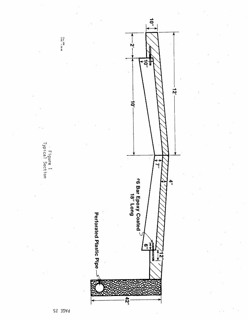
life of the concrete slab. This 4" perforated plastic pipe
was placed approximately 42" deep in a 10" wide trench with
porous backfill (Figure I). This has been proven to be very
successful on other projects.
The overall plan for this project was to overlay and widen
one-half of the roadway, place the shoulder material adjacent
to it the following day, and open it to contractor and local
traffic while the other side of the roadway is being prepared
for overlay and widening (Figure 11).

MATERIALS
This research-type project included a number of innovative
features. Each one of which was intended to solve a specific
problem. The number one item was the use of strength acceler-
ators. Calcium chloride was tried in small amounts on this
project to ensure that the concrete at driveways and county
road intersections would be sufficiently strong to open to
traffic the following day. This was very successful. This
particular project specified a special Type 111 cement. Part
of the specifications required that this material meet AASHTO
M-85 Type I11 portland cement. In addition, the ASTM C309
compressive mortar strength must reach at least 1300 PSI in 12
hours. This was necessary because of a wide variation found
in the strength of concrete from cements that met the regular
Type 111 requirements.
Epoxy-coated reinforcing steel was used to tie across longi-
tudinal random cracks to eliminate or control reflective
cracks. Additionally, in an attempt to better control exist-
ing transverse random cracks and reflection through the sur-
face, four-mil plastic tape 4 inches wide with pressure
sensitive adhesive was placed over random cracks and a control
joint was sawed within the limits of the tape. The intent was
to yield a transverse saw cut that could be maintained much
easier than a random crack.
A thermal blanket was used over this special. Type 111 cement.
It was recognized that a lot of heat is generated chemically
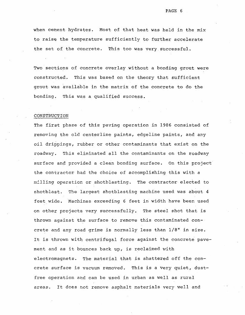
when cement hydrates. Most of that heat was held in the mix
to raise the temperature sufficiently to further accelerate
the set of the concrete. This too was very successful.
Two sections of concrete overlay without a bonding grout were
constructed. This was based on the theory that sufficient
grout was available in the matrix of the concrete to do the
bonding. This was a qualified success.
CONSTRUCTION
The first phase of this paving operation in 1986 consisted of
removing the old centerline paints, edgeline paints, and any
oil drippings, rubber or other contaminants that exist on the
roadway. This eliminated all the contaminants on the roadway
surface and provided a clean bonding surface. On this project
the contractor had the choice of accomplishing this with a
milling operation or shotblastiny. The contractor elected to
shotblast. The largest shotblasting machine used was about 4
feet wide. Machines exceeding 6 feet in width have been used
on other projects very successfully. The steel shot that is
thrown against the surface to remove this contaminated con-
crete and any road grime is normally less than 1/8" in size.
It is thrown with centrifugal force against the concrete pave-
ment and as it bounces back up, is reclaimed with
electromagnets. The material that is shattered off the con-
crete surface is vacuum removed. This is a very quiet, dust-
free operation ahd can be used in urban as well as rural
areas. It does not remove asphalt materials very well and

PAGE 7
quite often requires two or more passes to remove tightly ad-
hered materials like centerline paint. The end result, how-
ever, is very satisfactory.
Because this project called for a 2' widened section to be at-
tached to the old pavement and a stabilized crushed stone
shoulder to be placed outside the widening unit, the contrac-
tor's next operation involved removing the shoulder material
with a CMI subgrader working from a nylon stringline. The
stringline was placed with vertical reference to the outside
edge of the slab and with horizontal reference to the
centerline of the slab so that future passes of other equip-
ment could coincide with both the elevation of the finished
slab and the location of the centerline. The removal of this
subgrade material from the shoulder with the CMI equipment
proved to be a very intelligent move on the part of the con-
tractor. These shoulder materials tend to form hard clay
balls which would have been difficult to shape and grade at
later stages of the work. The loose grained material removed
by the subgrader was easily finished to the desired cross sec-
tion.
The next operation the contractor performed was to drill holes
3" down from the top of the edge of the slab at 2-foot centers
6" deep. These holes were to receive # 6 epoxy-coated tie bars
18" in length whose primary purpose was to tie the widening
unit to the main slab. The contractor had a drill rig de-
signed that would drill four holes at a time. These were hy-

draulic drills that had compressed air to blow the holes clean
once they had been drilled. This is a very satisfactory unit
and the rate of progress of this machine was estimated to be
1-1/2 miles in a day. Once the holes had been blown clean,
the contractor had to glue the rebars in place with a pull-out
strength of 1 0 , 0 0 0 pounds or more. This was accomplished with
a special two-component epoxy that was blended in the applica-
tion nozzle. This was then injected into the back of the hole
for a metered period of time. The rebar was stuck into the
hole and tapped into place to make sure that it had penetrated
the full 6 inches of the depth of the hole. This left approx-
imately one foot of rebar in the widening unit. Tests on the
pull-out strength of these bars were very satisfactory, reach-
ing approximately 1 5 , 0 0 0 pounds in four hours.
A number of surface spalls on this project were corrected by
milling partial depth with a milling machine and placing par-
tial depth patches at the time that the 4" overlay was placed.
Past experience had indicated that it was beneficial to place
reinforcing steel in these partial depth patches to prevent
reflective cracking in or around the patch itself. The main
problem with these partial depth patches being open and ex-
posed is that the batch trucks bent the rebars and that the
paver dropped down into the excavated hole, causing a rougher
ride than would have been produced had the patches been placed
prior to paving.

One of the very pleasant parts of this project was the success
of placing reinforcing bars across random cracks at approxi-
mately 30" intervals to control the random cracks. These # 5
bars were 36" long and epoxy coated. Very good strengths de-
veloped across these cracks and reflective cracking was re-
duced. This is probably partially due to the fact that the
concrete slab did not go into tension or shrink until the bond
strength, as measured by flexural strength, had exceeded 400
PSI. This process of placing tie bars across existing cracks
and some joints was very liberally used. By placing the tie
bars at right angles to the cracks and joints, it was antic-
ipated that the crack would not reflect through the 4" over-
lay.
The contractor was required to sandblast and airblast the sur-
face to be overlaid immediately in front of the paver. New
specifications may require the shotblasting equipment to oper-
ate immediately in front of the paver to remove any soil or
contaminants from the surface. This would ensure maximum bond
strength. The overlay and widening operation was basically
the same for attaching the second unit to the existing slab
except the centerline joint had to be kept clean. This was a
minor problem due to the rainy season and wind causing some
contamination of the roadway surface. This seemed to accumu-
late against the vertical edge of the centerline joint that
was exposed. It required substantial effort on the part of
the contractor to keep the prepared surface clean so that a
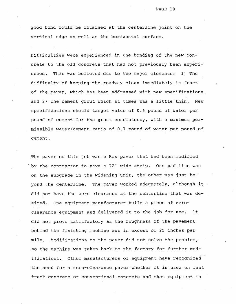
good bond could be obtained at the centerline joint on the
vertical edge as well as the horizontal surface.
Difficulties were experienced in the bonding of the new con-
crete to the old concrete that had not previously been experi-
enced. This was believed due to two major elements: 1) The
difficulty of keeping the roadway clean immediately in front
of the paver, which has been addressed with new specifications
and 2) The cement grout which at times was a little thin. New
specifications should target value of 0.6 pound of water per
pound of cement for the grout consistency, with a maximum per-
missible water/cement ratio of 0.7 pound of water per pound of
cement.
The paver on this job was a Rex paver that had been modified
by the contractor to pave a 12' wide strip. One pad line was
on the subgrade in the widening unit, the other was just be-
yond the centerline. The paver worked adequately, although it
did not have the zero clearance at the centerline that was de-
sired. One equipment manufacturer built a piece of zero-
clearance equipment and delivered it to the job for use. It
did not prove satisfactory as the roughness of the pavement
behind the finishing machine was in excess of 25 inches per
mile. Modifications to the paver did not solve the problem,
so the machine was taken back to the factory for further mod-
ifications. Other manufacturers of equipment have recognized
the need for a zero-clearance paver whether it is used on fast
track concrete or conventional concrete and that equipment is

now available. The bonded overlay specifications required a
smoothness measured with the 25-Foot Profilometer not greater
than 15 inches per mile. When the operation was going well,
smoothness in the vicinity of 8 " to 10'' per mile was obtained.
It would be desirable on future projects that traffic be main-
tained in the lane adjacent to the paver. Although local
traffic was maintained on this project at all times, some
flagging took place at the paver as the paving operation did
extend into the adjacent lane. The contractor, from time to
time, had problems with the vertical edge at the centerline
and his finishing crews had to intrude into the traffic lane.
It is proposed that this will be restricted on future
projects. In paving the second pass with the paving machine,
one tread of the paver had to operate in the trench that was
cut for the widening unit and one tread of the machine trav-
eled on the previously placed thin bonded overlay. This
worked very satisfactory.
The pavement texture was obtained by a longitudinal astro-
grass drag followed by transverse grooving. A liquid curing
compound was then applied as soon as the texturing was com-
pleted in order to minimize the evaporation of water from the
surface. This step was necessary, because it was the plan to
saw the transverse joints prior to applying the thermal blan-
ket. The contractor was allowed to make the transverse cuts 3
to 4 hours after placement. At that time, it was very plain
to see that although the concrete had set up, the curing com-
pound was not entirely dry, and the tracks of the saw machine
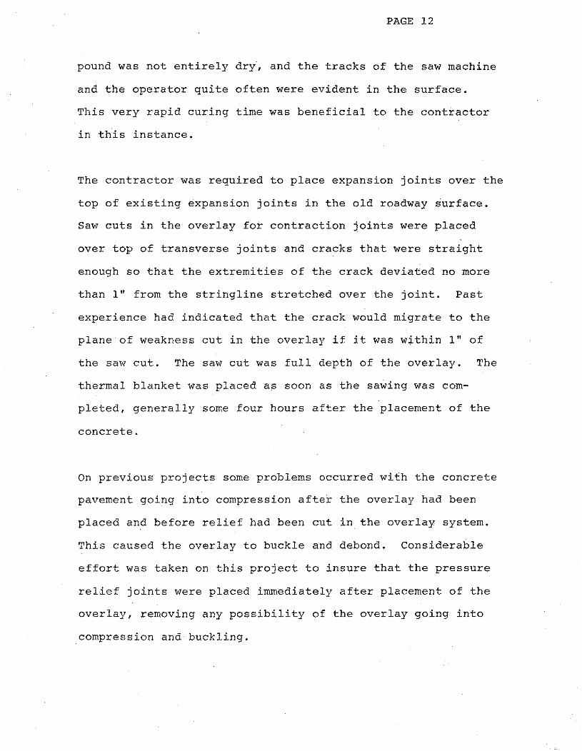
and the operator quite often were evident in the surface.
This very rapid curing time was beneficial to the contractor
in this instance.
The contractor was required to place expansion joints over the
top of existing expansion joints in the old roadway surface.
Saw cuts in the overlay for contraction joints were placed
over top of transverse joints and cracks that were straight
enough so that the extremities of the crack deviated no more
than 1" from the stringline stretched over the joint. Past
experience had indicated that the crack would migrate to the
plane of weakness cut in the overlap if it was within 1" of
the saw cut. The saw cut was full depth of the overlay. The
thermal blanket was placed as soon as the sawing was com-
pleted, generally some four hours after the placement of the
concrete.
On previous projects some problems occurred with the concrete
pavement going into compression after the overlay had been
placed and before relief had been cut in the overlay system.
This caused the overlay to buckle and debond. Considerable
effort was taken on this project to insure that the pressure
relief joints were placed immediately after placement of the
overlay, removing any possibility of the overlay going into
compression and buckling.

It was intended that the new centerline joint be as close to i
the old centerline joint as possible. The paver was con-
trolled by a nylon line from the shoulder and the centerline
joint was usually within an inch of the old centerline joint
and it was anticipated that the crack would reflect within an
inch of the old joint. In some instances the inspection per-
sonnel wrote on the surface of the pavement prior to the sec-
ond pass on the machine, which way the centerline joint was to
be moved when it was sawed so that the joint would reflect
through immediately over top of the old joint and prevent two
centerline joints in the area. In spite of all this effort,
there are some areas where cracks exist adjacent to sawed
joints.
The completed roadway is 24' wide, has 6' crushed stone stabi-
lized shoulders and. is very adequate to carry the projected
3,000 vehicles per day.
ICEST DATA
Much of the concrete placed had a temperature of approximately
90°F at the time of placement (Figure 111). After consol-
idation, placement, sawing of joints, and covering with a
thermal blanket, the temperature rise continued under the
thermal blanket for several hours but by the next morning it
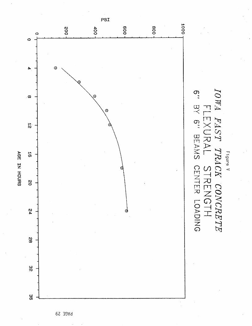
had started to cool (Figure IV). The average strength of
beams which were tested with center point loading on this
project was 390 psi in eight hours and 490 psi in twelve hours
(Figure V ) . The 24-hour beam strength was 600 psi. The

seven-day strength was 720 psi and the 14-day 820 psi. These
values show that this was a high strength concrete and it did
gain flexural strength rapidly. The rise in compressive
strength was not quite as dramatic but was very good. The
8-hour compressive strength of 6 inch by 12 inch cylinders was
approximately 1900 psi, over 2500 psi in 12 hours, 3500 psi in
24 hours, 5,000 psi in seven days and 5,300 psi in 14 days
(Figure VI and VII) .
The mix that was used on this project is paramount to the suc-
cess of the fast track concrete. The contractor elected to
use 640 pound of special Type I11 cement, and 70 pounds of
Type C approved fly ash. It was targeted for 6 1/2 percent
entrained air and an approved and compatible water reducing
agent was used. Forty-five percent fine a.ggregate and fifty-
five percent coarse aggregate was incorporated into the mix
The slump was maintained at about 1 1/2 inches. The water-
cement ratio was generally in the area of 0.43 to 0.45 pounds
of water per pound of cement. This concrete was placed during
the month of July when the temperatures are in the vicinity of
90°F during the day and slightly over 60°F at night. The tem-
perature under the thermal blanket, the evening following the
day that it was placed, generally reached 115OF or slightly
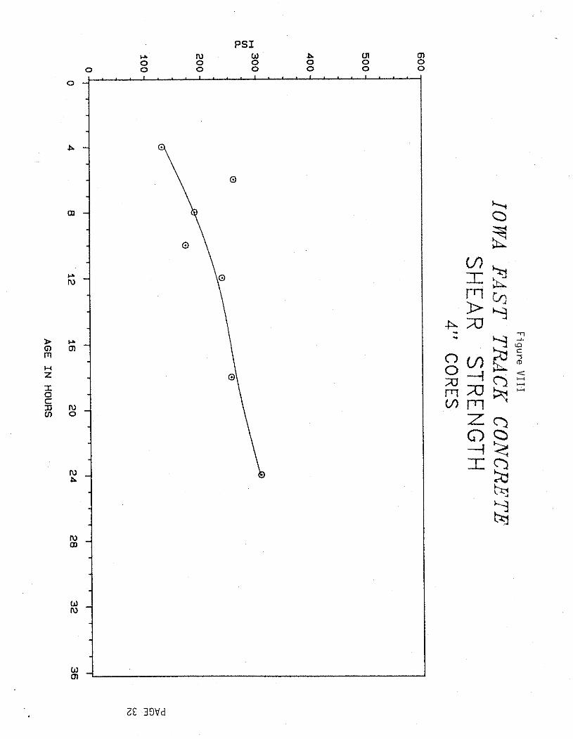
more. The flexural strength (center point loading of 6 inch
by 6 inch beams) was approximately 600 psi in 24 hours and the
bond strength measured by a direct shear test was slightly
sidered to be very adequate.

PAGE 15
The results from this project have been very successful to
date. Test data indicates that this is a very acceptable
method of placing concrete and opening it to traffic in 24
hours. As additional data on this type of work is gained and
specifications and special provisions are fine tuned, results
will be even better than that attained on this first project.
EVALUATION AT ONE YEAR
The project was evaluated again in May 1987 after the first
winter. Testing at one year included visual observations,
core conditions, and various test results including core
compressive strength, direct shear tests on cores for bond
strength, profilomet.er results and Delamtect test results.
In general terms, the pavement condition appeared the same af-
ter one year as it was immediately after completion. There
was no apparent distress related to traffic usage or to the
severe winter conditions.
A close examination revealed a small amount of additional
transverse cracking which appeared after one year. This addi-
tional cracking is associated with the reflective cracking at
mid-panel in the old pavement and apparently was not visible
when the majority of reflective cracks were sawed with a crack
saw and sealed. Initially, those joints that deviated more
than one inch from the stringline were allowed to reflective
crack. About six months after construction of the overlay, a

small diameter crack saw was used to yield a reservoir. The
reservoir was then filled with Sof Seal joint seal material.
As estimated, 3500 feet of additional crack sawing and sealing
was done.
At isolated locations a multiple transverse crack pattern has
developed in the vicinity of the mid-panel cracks in the old
pavement and there is also a tendency for minor debonding to
occur at the mid-panel cracks. The Delamtect report is at-
tached and shows delamination in the direct vicinity of the
transverse reflective cracks. Debonding is very minor and
based on past experience is not considered a serious threat to
long term performance.
The cause of the debonding is thought to be related to the
slight crack closure in the old pavement after overlay place-
ment and during the time of maximum temperature while the in-
sulated covers were in place. Even though crack closure was
restricted by incompressibles in the crack, it appears there
was enough minor closure to cause a tendency for debonding.
This same condition appears to have caused the minor amount of
multiple transverse cracks in these same areas.
TESTS CONDUCTED AT ONE YEAR
Compressive strength of the concrete as shown by the strength
of cores is very high and shows normal continued strength gain
since the previous summer. In general, the concrete contain-

ing calcium chloride is a little higher strength than concrete
without calcium chloride (Figure XI).
The average strength of age 2 9 5 days was as follows:
Noncalcium Chloride 1% Calcium Chloride
Avg. of 3 - 6160 PSI, Avg. of 3 - 6690 PSI
Direct shear testing at the bond line shows the average bond
strength has decreased slightly. The decrease is considered
minor and not significant. The bond strength is a little
lower than anticipated but is satisfactory and well above the
minimum considered necessary to cause the old pavement and the
new overlay to work together as a structural unit.
Surface Treatment
Shear Strength (PSI
Avg. Shear Strength (PSI)
Type I Grout 338
2 9 4 316
Type I11 Grout
Non Grouted

PAGE 1 8
Type I Grout & Double Shot Blast
Three 1 0 0 0 feet long test sections were selected for debonding
study. The Delamtect tested along centerline in each direc-
tion within one or two feet of centerline. Results are shown
in the attached Delamtect survey tabulations. The abbrevi-
ations LT and RT represent left and right wheel tracks respec-
tively. It is noted nearly all delamination occurs in the
left track near centerline.
Based on these results delamination percentage could be calcu-
lated as follows:
3 linear feet of delamination = 0.05%
6000 x 100
41 linear feet of delamination = 0 .68%
6000 x 100

Although delaminations have increased since initial testing,
it is considered minor and is not cause for concern.
Road Rater deflection testing was completed June 23, 1986 just
prior to overlay construction. It was repeated April 4, 1987.
The average structural rating (SR) at mid-panel in 1986 prior
to overlay was 3.49 and at the joints was 3.27. The average
soil K values in 1986 were 58 at mid-panel and 76 at the
joints. In 1987 the average SR at mid-panel is 6.04 and at
the joints is 4.21. The average soil K values in 1987 are 144
at mid-panel and 175 at the joints.
These test results show significant improvement in the pave-
ment structural system, which is thought to result from se-
veral beneficial features: additional composite pavement
thickness, relocating the outside wheel track to a position
where the pavement thickness is at a maximum, improved sub-
grade conditions resulting from longitudinal drains and sur-
face joint sealing, and improved structural capacity because
of the tied and monolithic widening.
Road Rater test results show the new composite unit is struc-
turally adequate to carry current and projected traffic.
Profilometer testing was accomplished by the contractor in
1986 following overlay placement. Profilometer testing was
accomplished by the Iowa Department of Transportation
April 10, 1987.

Results for representative sections are as follows:
Profile Index (in./mi.) 1986 1987
Station 498+94 to 502+26 SB 13.50 11.50
521+41 to 526+69 NB 8.00 7.50
576+00 to 581+28 NB 18.50 20.50
628+60 to 633+88 NB 16.50 13.00
719+64 to 724+92 NB 9.50 8.50
These results are interpreted to show there was no perceptible
deterioration of the ride quality since rehabilitation con-
struction in 1986.
Debonding tape was placed over three transverse cracks in the
old pavement just prior to overlay placement. The tape was 4
mil plastic by 4 inches wide with adhesive on one side. It
was placed transversely across the driving lane and about 8
inches wide (two widths alongside each other) so that the
total tape width covered the old transverse crack. The over-
lay was then placed and contraction joint was sawed full depth
of the overlay inside the bounds of the debonding tape. The
goal was to control reflective cracking in the overlay and
transform a crack in the old pavement into a straight sawed
joint in the overlay.
PAGE 21
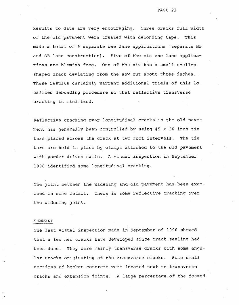
Results to date are very encouraging. Three cracks full width
of the old pavement were treated with debonding tape. This
made a total of 6 separate one lane applications (separate NB
and SB lane construction). Five of the six one lane applica-
tions are blemish free. One of the six has a small scallop
shaped crack deviating from the saw cut about three inches.
These results certainly warrant additional trials of this lo-
calized debonding procedure so that reflective transverse
cracking is minimized.
Reflective cracking over longitudinal cracks in the old pave-
ment has generally been controlled by using # 5 x 30 inch tie
bars placed across the crack at two foot intervals. The tie
bars are held in place by clamps attached to the old pavement
with powder driven nails. A visual inspection in September
1990 identified some longitudinal cracking.
The joint between the widening and old pavement has been exam-
ined in some detail. There is some reflective cracking over
the widening joint.
SUWfARY
The last visual inspection made in September of 1990 showed
that a few new cracks have developed since crack sealing had
been done. They were mainly transverse cracks with some angu-
lar cracks originating at the transverse cracks. Some small
sections of broken concrete were located next to transverse
cracks and expansion joints. A large percentage of the foamed

PAGE 22
expansion joint material has partially or completely come out
of the sawed four-inch expansion joints.
In summary, the pavement condition and performance is consid-
ered very satisfactory and is expected to give good service
for an extended number of years. The concept of single lane
construction to permit usage of the adjacent lane for public
and construction traffic is considered viable.
Additional information and experience in needed on future
projects to explore controlling reflective transverse crack by
using debonding tape. If this is successful, debonding near
the transverse cracks and associated multiple cracking because
of elevated curing temperature will be eliminated or mini-
mized.
An Iowa Department of Transportation review panel of design,
construction and materials pavement specialists viewed this
project along with 8 other bonded overlay projects in April
1987 and based on their judgment projected a service life for
this project of 20 to 30 years.

CONCLUSIONS
This research on thin bonded concrete overlay with fast track
concrete supports the following conclusions:
I . The bonded overlay is performing well with a projected
life of 20 to 30 years.
2. Random reflective transverse cracking has been minimized
with the use of debonding tape.
3. The use of fast track concrete makes it possible to open
roads to the public in 24 hours.

PAGE 2 4
Appendix F igu re s of Ske tches and Graphs
#6 Bar E
po
xy Co
ated
Perfo
rated P
lastic Pip
e
Fig
ure
I T
yp
ica
l S
ec
tion

PAGE 26

Fig
ure I11
IOW
A
FA
ST
T
RA
CK
C
ON
CR
ET
E
CO
NC
RE
TE
M
IX TE
MP
ER
ATU
RE

r(
ISd
Fig
ure
V
IO?t<
4 FA
ST
T
R4C
Ic C
ON
CR
ET
E
FLE
XU
RA
L STR
EN
GTH
6"
3Y
6" E3EAM
S C
EN
TER
LO
AD
ING
1000
800 -
60
0 -
H
(I) a
400 -
200 -
0
0,
".
1"
'1
."
IS
.
'I
'"
I"
'l
"'
l"
'l
"'
l
0
4
8
12
1
6
20
2
4
28
32
36
AG
E IN
HOURS

ISd

Figu
re VII
A
FA
ST
T
RA
CK
C
OLITC
RE
TE:
CO
MP
RE
SS
IVE
S
TRE
NG
TH
6" B
Y
12
" C
YLIN
DER
S
AG
E IN
DA
YS
Figu
re VIII
IOW
A
FA
ST
T
RA
CK
C
ON
CR
ET
E
SH
EA
R
STR
EN
GTH
4"
CO
RE
S
0
4
8
12
16
20
24
28
32
36
AG
E IN H
OU
RS

ISd