thick ysz films prepared via a modified sol–gel route: thickness control (8–80 μm)
TRANSCRIPT

A
DwtoFt
©
K
1
cccttp
etasimro
B2
0d
Journal of the European Ceramic Society 26 (2006) 3153–3160
Thick YSZ films prepared via a modified sol–gel route:Thickness control (8–80 �m)
M. Gaudon a, Ch. Laberty-Robert a,∗, F. Ansart a, P. Stevens b
a CIRIMAT, LCMIE, UPS, Bat II R1, 118 route de Narbonne, 31062 Toulouse, Cedex 04, Franceb EDF, European Institute for Energy Research, Karlsruhe, Germany
Received 14 February 2005; received in revised form 30 August 2005; accepted 16 September 2005Available online 19 October 2005
bstract
ip-coated suspensions were used for preparing YSZ layers on both dense and porous substrates. The microstructure of the as-obtained thick filmsas studied by varying the characteristics of the organic YSZ suspensions (concentration, viscosity, etc.) used as coating bath. The thickness and
he microstructure of the films were found to depend on the YSZ powder content and on the polymeric sol/dispersant solution (EtOH–MEK) ratiof the suspensions. The porosity created in the films depends on the rm ratio, e.g., the volume fraction of polymeric chains in the green layers.
inally, a comparison of the film thickness on dense and porous substrates showed that films prepared on porous substrates tend to exhibit higherhicknesses.Accordingly, YSZ ceramic films with thickness varying in between 8 and 80 �m were prepared.2005 Elsevier Ltd. All rights reserved.
thods
etmate
iSicsnt(
eywords: Solid oxide fuel cell (SOFC); Suspensions; YSZ; ZrO2; Sol–gel me
. Introduction
A lower operating temperature (<700 ◦C) for solid oxide fuelells (SOFCs) enables high temperature steels to be used as inter-onnect materials, which significantly decreases the cost of theell, and increases the reliability of SOFC stacks.1–6 However,he major drawback in decreasing the working temperature ishat it greatly decreases the performance of the other cell com-onents, especially the electrolyte.
Current SOFC development focuses on the research of newlectrolyte materials exhibiting better ionic conductivity thanhe conventional yttria-stabilized zirconia (YSZ) at intermedi-te temperatures.7 However, a thin film concept for electrode-upported designs based on the well-known YSZ is more promis-ng, even though it has a lower ionic conductivity than other new
aterials. Keeping yttria-stabilized zirconia as electrolyte mate-ial, the electrolyte membrane should be as thin as possible inrder to have ohmic losses in a cell at a tolerable level but thick
∗ Corresponding author at: Naval Research Laboratory, Surface Chemistryranch, Code 6171, 4555 Overlook Avenue, South West, Washington, DC0375, USA. Tel.: +1 202 767 1344; fax: +1 202 767 3321.
E-mail address: [email protected] (Ch. Laberty-Robert).
iuotppup
955-2219/$ – see front matter © 2005 Elsevier Ltd. All rights reserved.oi:10.1016/j.jeurceramsoc.2005.09.026
; Films
nough to maintain gas tightness and avoid pin-holes. Amonghe other advantages of using thin electrolytes are the reduced
aterials costs and the improved fuel cell characteristics.8 Innode supported SOFCs, good cell performances includingimelife and power density were obtained with 10–20 �m YSZlectrolytes.9–11
So far, various thin film deposition methods have been usedn the fabrication of electrolytes for intermediate temperatureOFC such as electrochemical vapor deposition (EVD),12 phys-
cal vapor deposition (PVD),13 vacuum plasma spraying,14 tape-asting,15 screen-printing,16 and spray pyrolisis.17 However, theol–gel process method has seldom been applied for SOFC tech-ology. The dip-coating of sol or gel is a coating technologyhat has the potential to produce thin (0.1–1 �m) and gas-tightcrack-free) ceramic layers on dense substrates.18–22 However, its difficult to prepare gas-tight film on a porous substrate, even bysing multiple layer technology. In this work, a suspension madef sol and particles was investigated in order to increase the filmhickness. To our knowledge, only few studies of the use of sus-
ensions with the dip-coating technique have been presented torepare films with a controlled thickness. Xia et al.23 reported these of YSZ powders in ethanol as dip-coated suspensions for thereparation of yttria-stabilized zirconia membranes on porous
3 ean C
siliatsalp
patmdctfidaowhtsstiE
2
2
t3sFewmpbc1ow
2fi
ddc
afocmcuf
iaweaTi3ootwabasi5s
pamrsr
fi1(aTmarafi
2
2
is
154 M. Gaudon et al. / Journal of the Europ
ubstrates. Their YSZ powders were obtained via a soft chem-stry route, namely coprecipitation. However, the films exhibitow thickness and cracks. A multilayer process was consideredn order to prevent cracks and to obtain higher thickness. Someuthors also mentioned the use of hybrid sol/powder systemso impregnate honeycomb.24 The advantage of using a hybridystem is to limit the sol infiltration into the support pores whilechieving satisfactory loading. These results are mostly corre-ated to the combination of the properties of the sols and theowders.
In this study, we develop a sol–gel-based strategy for theroduction of YSZ thick films with controlled thickness. Ourpproach to synthesize these films is based on the formulation ofhe dip-coated suspensions. These suspensions are obtained by
ixing optimized slurries for tape casting and polymeric sol forip-coating. A well-dispersed suspension of polymeric sol anderamic particles was achieved by particles surface modifica-ion, which is very important in order to get homogeneous thicklms. Upon mixing the two solutions (polymeric sol and YSZispersed in ethanol/methylethylcetone (60/40) (EtOH–MEK)zeotropic solution), a flocculation of particles with polymerccurs via electrostatic attraction and/or steric effect. Comparedith common methods used to prepare thick films, our strategyas several advantages among which the fact that the forma-ion of flocculated suspensions makes it possible to deposit theuspension via the dip-coating process on YSZ dense or porousubstrates and to obtain homogeneous films. The morphology ofhe films, their porosity as well as their thickness, can be read-ly adjusted by changing the volume ratio of polymeric sol totOH–MEK solution and the powder content in the suspensions.
. Experimental
.1. Materials
Yttria-stabilized zirconia (8 mol% yttria cubic zirconia crys-als) powders (TOSOH, Co) with an average particles size of0 nm were used as materials in the experiments. The disper-ant was commercial MELIORAN®, anionic surfactant (CECArance, Archema Group, viscosity: 30–35 mPa s). Two differ-nt substrates, with different microstructure and compositionere used for the YSZ films synthesis. NiO–YSZ Cermetsanufactured by InDEC,BV Company, Holland, were used as
orous substrates. These substrates present pore sizes varyingetween 200 nm and 5 �m and an open porosity of ≈15%. YSZeramic pellets manufactured by LEPMI, INPG, Grenoble ofmm thick × 20 mm diameter were used as dense substrates. Inrder to get good adhesion on the YSZ ceramics, the substratesere first polished down to an average roughness of 10 nm.
.2. Formulation of the suspensions and processing for YSZlms
YSZ thick films were prepared by dip-coating both porous orense substrates in the suspension. The YSZ powder was firstispersed in EtOH–MEK (60–40) azeotropic mixtures by using aommercial dispersant (MELIORAN®). This dispersive solvent
st
s
eramic Society 26 (2006) 3153–3160
nd dispersant were chosen according to Chartier’s work on theormulation of slurries for tape-casting process.25–27 In order tobtain a homogeneous suspension, 2.5% in weight of dispersantompared to YSZ powder was first dispersed in the azeotropicixture and then powder (>20% in weight) was added under
onstant magnetic stirring. Attempts to synthesize suspensionssing YSZ/MEK–EtOH solution had shown that no film wasormed on the YSZ substrates using the dip-coating technique.28
A polymeric matrix may then be introduced to the suspensionn order to obtain suitable wettability and viscosity (>5 mPa s),nd then formation of uniform film. The polymeric solutionas obtained from polycondensation reactions between hexam-
thylenetetramine (HMTA) and acetylacetone (Acac) in aceticcid. The molar ration between HMTA and Acac was 1:1.he viscosity of the polymeric matrix was adjusted by heat-
ng (∼70 ◦C, under constant stirring) and was kept constant to0 mPa s. Preliminary investigations had shown that the statef dispersion of powders in this new mixture is affected by therder of introduction of the different additives.28 Accordingly,his polymeric matrix was first added to the azeotrope media inhich YSZ powders were first well dispersed by using Melioran
s dispersant. The mixing of both solutions was then achievedy vigorous magnetic stirring during a couple of hours. Previousttempts had shown that in order to obtain films with a thicknessuperior to 1 �m, the powder content must be superior to 20%n weight. Lower powder content gave rise to film’s thickness of0–150 nm. This is mostly correlated to the low viscosity of theuspension for this powder loading (5 mPa s).
The rheological behavior of the dip-coated suspensions (YSZowder/polymeric sol/MEK–EtOH solution) was then studiednd it was shown to depend on the powder content and the volu-etric ratio of polymeric sol/ azeotropic EtOH–MEK, so-called
m. The number of polymeric chains in these dip-coated suspen-ions is correlated to the rm ratio. In the flowchart of Fig. 1 areeported the key points of the synthesis process.
A withdrawal speed of 1.2 cm min−1 was used to prepare thelms. After the dip-coating process, the YSZ films were dried at00 ◦C and were then finally heated to the desired temperature1300 ◦C) by using a ramp of 2 ◦C min−1, kept at this temper-ture for 6 h and then allowed to cool to ambient temperature.hermal treatments were performed in air. Preliminary experi-ents had shown that the drying rate of the as-prepared films
ffects the cracks number and morphology. The lower dryingate conduces to the formation of fewer cracks.27 Accordingly,mbient temperature drying was first used for the as-preparedlms.
.3. Characterization
.3.1. RheologyA rheometer (Rheomat-115) was used to determine rheolog-
cal properties of all suspensions at 25 ◦C. Each suspension wasubjected to an increasing shear rate from 5 to 1000 s−1 with a
peed varying in the range of 5 to 780 min−1. The shear rate washen subsequently reduced to 5 s−1.Apparent viscosity of sols was measured with a rotating-pindle viscometer (Tve-05). The shear stress was 66.5 s−1.

M. Gaudon et al. / Journal of the European Ceramic Society 26 (2006) 3153–3160 3155
-coate
Tbi
2
gSssus
2
u
pceC
ufia
3
Fig. 1. Schematic of the YSZ dip
he apparent viscosity of sols was measured at this shear stressecause it represents the conditions, which are reached at thenterface suspension/substrate during the dip-coating process.
.3.2. Sedimentation testsSedimentation tests were performed by pouring 50 mL of a
iven suspension into a 50 mL graduated Pyrex glass cylinder.ediment heights were recorded after 72 h. In a typical suspen-ion, 10 g of YSZ powder was first dispersed in EtOH–MEKolution and the polymeric sol was then added to it. The vol-metric ratio between the polymeric sol and the EtOH–MEKolution (rm) varied between 0.05 and 0.5.
.3.3. Characterization of filmsThick films with different microstructures were prepared by
sing different powders content and rm ratio.
3
p
d suspensions used in this work.
XRD analysis was performed in order to confirm that therocessing (heating, dip-coated process) has no influence on therystallographic structure of the YSZ powders. Siemens D501quipment was used for collecting X-rays diffraction data. Theu K� lines were used as a source.
Scanning electron microscopy (SEM) (JEOL-JSM6400) wassed to investigate the morphology evolution of the as-depositedlms after heat-treatment. The YSZ powder morphology waslso determined from SEM analyses.
. Results and discussion
.1. Films on dense substrates
The microstructure of the films is highly dependent on theroperties of the starting materials and the suspension prop-
3156 M. Gaudon et al. / Journal of the European Ceramic Society 26 (2006) 3153–3160
epmgwoi
3o
sso
TuarrtrbwIlfl
ns
Tn
r
τ
An
Fr
Tlrpo
tivrri
cptFdasTpa
ltfs
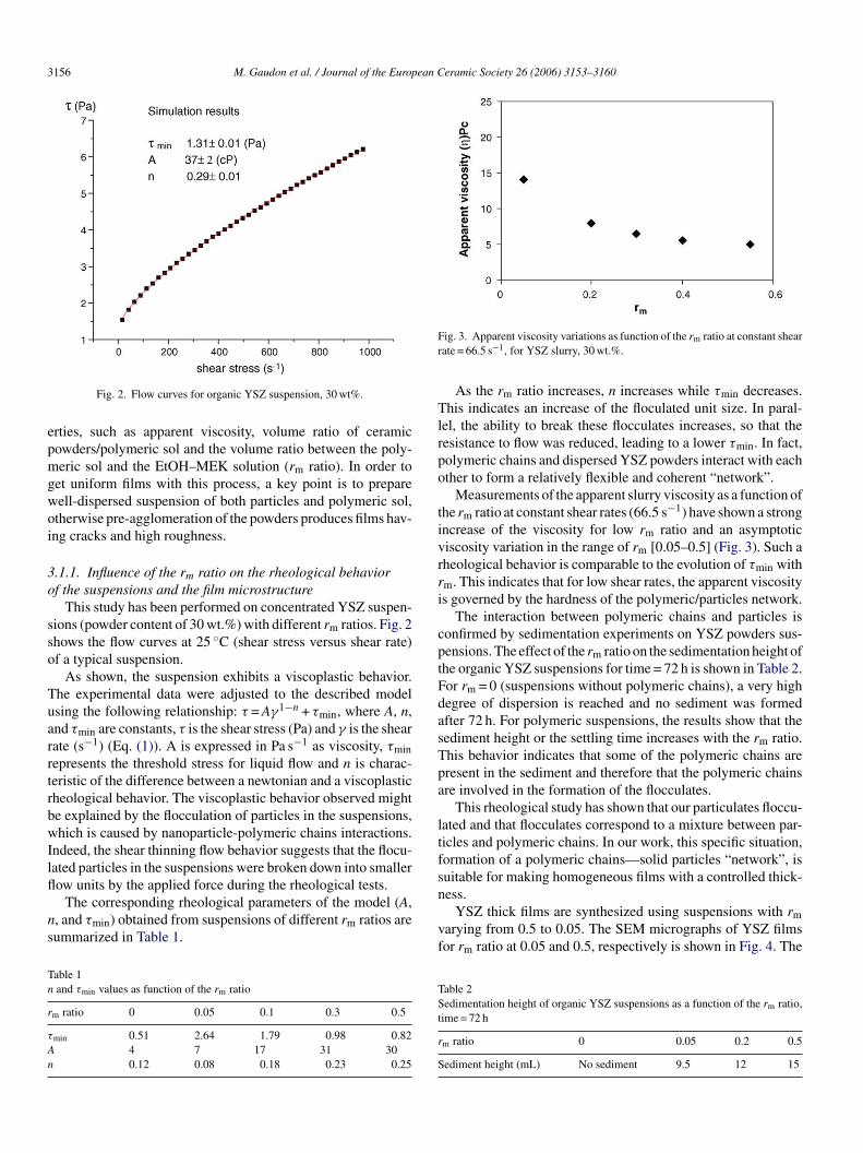
Fig. 2. Flow curves for organic YSZ suspension, 30 wt%.
rties, such as apparent viscosity, volume ratio of ceramicowders/polymeric sol and the volume ratio between the poly-eric sol and the EtOH–MEK solution (rm ratio). In order to
et uniform films with this process, a key point is to prepareell-dispersed suspension of both particles and polymeric sol,therwise pre-agglomeration of the powders produces films hav-ng cracks and high roughness.
.1.1. Influence of the rm ratio on the rheological behaviorf the suspensions and the film microstructure
This study has been performed on concentrated YSZ suspen-ions (powder content of 30 wt.%) with different rm ratios. Fig. 2hows the flow curves at 25 ◦C (shear stress versus shear rate)f a typical suspension.
As shown, the suspension exhibits a viscoplastic behavior.he experimental data were adjusted to the described modelsing the following relationship: τ = Aγ1−n + τmin, where A, n,nd τmin are constants, τ is the shear stress (Pa) and γ is the shearate (s−1) (Eq. (1)). A is expressed in Pa s−1 as viscosity, τminepresents the threshold stress for liquid flow and n is charac-eristic of the difference between a newtonian and a viscoplasticheological behavior. The viscoplastic behavior observed mighte explained by the flocculation of particles in the suspensions,hich is caused by nanoparticle-polymeric chains interactions.
ndeed, the shear thinning flow behavior suggests that the flocu-ated particles in the suspensions were broken down into smaller
ow units by the applied force during the rheological tests.The corresponding rheological parameters of the model (A,, and τmin) obtained from suspensions of different rm ratios areummarized in Table 1.
able 1and τmin values as function of the rm ratio
m ratio 0 0.05 0.1 0.3 0.5
min 0.51 2.64 1.79 0.98 0.824 7 17 31 300.12 0.08 0.18 0.23 0.25
n
vf
TSt
r
S
ig. 3. Apparent viscosity variations as function of the rm ratio at constant shearate = 66.5 s−1, for YSZ slurry, 30 wt.%.
As the rm ratio increases, n increases while τmin decreases.his indicates an increase of the floculated unit size. In paral-
el, the ability to break these flocculates increases, so that theesistance to flow was reduced, leading to a lower τmin. In fact,olymeric chains and dispersed YSZ powders interact with eachther to form a relatively flexible and coherent “network”.
Measurements of the apparent slurry viscosity as a function ofhe rm ratio at constant shear rates (66.5 s−1) have shown a strongncrease of the viscosity for low rm ratio and an asymptoticiscosity variation in the range of rm [0.05–0.5] (Fig. 3). Such aheological behavior is comparable to the evolution of τmin withm. This indicates that for low shear rates, the apparent viscositys governed by the hardness of the polymeric/particles network.
The interaction between polymeric chains and particles isonfirmed by sedimentation experiments on YSZ powders sus-ensions. The effect of the rm ratio on the sedimentation height ofhe organic YSZ suspensions for time = 72 h is shown in Table 2.or rm = 0 (suspensions without polymeric chains), a very highegree of dispersion is reached and no sediment was formedfter 72 h. For polymeric suspensions, the results show that theediment height or the settling time increases with the rm ratio.his behavior indicates that some of the polymeric chains areresent in the sediment and therefore that the polymeric chainsre involved in the formation of the flocculates.
This rheological study has shown that our particulates floccu-ated and that flocculates correspond to a mixture between par-icles and polymeric chains. In our work, this specific situation,ormation of a polymeric chains—solid particles “network”, isuitable for making homogeneous films with a controlled thick-ess.
YSZ thick films are synthesized using suspensions with rmarying from 0.5 to 0.05. The SEM micrographs of YSZ filmsor rm ratio at 0.05 and 0.5, respectively is shown in Fig. 4. The
able 2edimentation height of organic YSZ suspensions as a function of the rm ratio,
ime = 72 h
m ratio 0 0.05 0.2 0.5
ediment height (mL) No sediment 9.5 12 15

M. Gaudon et al. / Journal of the European Ceramic Society 26 (2006) 3153–3160 3157
t 1000
fiuwotttc
oes
dOoa
pts
3
ii
Fs
Ttaptwtrw0
h
wsdtctcrp
Fig. 4. Scanning electron micrographs of YSZ films heat-treated a
lms are continuous and homogeneous whatever the rm ratiosed in the suspensions. Fig. 4 shows that the films are poroushatever the rm ratio. Their porosity is correlated to the presencef polymeric chains in the dip-coated suspensions. Nevertheless,he microstructure (film thickness and porosity) is sensitive tohe rm ratio. High rm ratio in dip-coated suspensions correspondso thinner green films with high volume fraction of polymerichains. This is why thinner films still have porosity.
Note that for rm = 0, no value is reported on the graph becausef the inhomogeneity in the films that made the film thicknessvaluation impossible. This particular point corresponds to auspension without any polymer solution.
The evolution of the thickness as a function of the rm ratio isescribed by a decreasing asymptotic function, shown in Fig. 5.ne can see that the evolution of the layer thickness as a functionf the rm ratio presents similarities with the evolution of thepparent viscosity of the suspension (or shearing stress τmin).
Thus, for an identical powder content in the suspensions, it isossible to reach films with different thicknesses and microstruc-ure by changing the amount of polymeric chains in the suspen-ions.
.1.2. Study of the powder contentThe powder content in the suspensions is optimized in order to
ncrease the film density. Note that changing the powder contentn the YSZ suspension modifies, of course, the film thickness.
ig. 5. Film thickness as a function of rm ratio for 30 wt.% YSZ in the suspen-ions.
rortf
η
wcc
toic
figcco
◦C in air for 2 h from slurries with rm = 0.05 (a) and rm = 0.5 (b).
he SEM images of the cross-sectional view of YSZ films sin-ered at 1000 ◦C for 2 h for 60, 35, and 20 wt.% powder contentsre shown in Fig. 6. The thickness of the films evolves with theowder content, and the cross-section microstructure remainshe same whatever the thickness of the film. The film thicknessas then determined from these data. Its evolution as a func-
ion of the powder content in the suspensions for rm = 0.25 iseported in Fig. 7a. No linear variation of the film thicknessith a coefficient of about 1.8 with a correlation factor R2 of.9991 according to the following equation:
= KexpT%1.8 (1)
here h represents the film thickness, Kexp an experimental con-tant including the viscosity of the dip-coated solution, theirensity, the withdrawal speed and, T% the powder content inhe dip-coated suspension. Note that the viscosity of the dip-oated solution had been previously studied. It had been shownhat the films’ thickness evolves as a function of the powderontent inside the dip-coated solution. This behavior is compa-able to the evolution of the films’ thickness as a function of theowder content.
The increase in the film thickness with the powder content,anging from 0 to 60%, is correlated to the apparent viscosityf the suspensions for a shear rate of 66.5 s−1. In the studiedange, the apparent viscosity of the suspension as a function ofhe powder content is reported in Fig. 7b, it follows a powerunction with a coefficient of 1.2:
= K1T%1.2 (2)
ith a correlation factor R2 of 0.9996, where T% is the powderontent, η the viscosity of the suspension and K1 an experimentalonstant.
This increase in the apparent viscosity with the powder con-ent can be related to two phenomena: the strong influencef the flocculated network or a stronger network due to anncrease in the interactions between particulates and polymerichains.
In the Landau and Levich law,29 the authors showed that thelm thickness (h0) is a balance of three forces: the forces of
ravity, the viscous drag force and the capillary force. In thisase, the thickness of the film (h, �m) is proportional to the vis-osity η (mPa s−1), the surface tension (σ, mJ m−2), the densityf the coating bath (ρ, g cm−3), the substrate speed withdrawal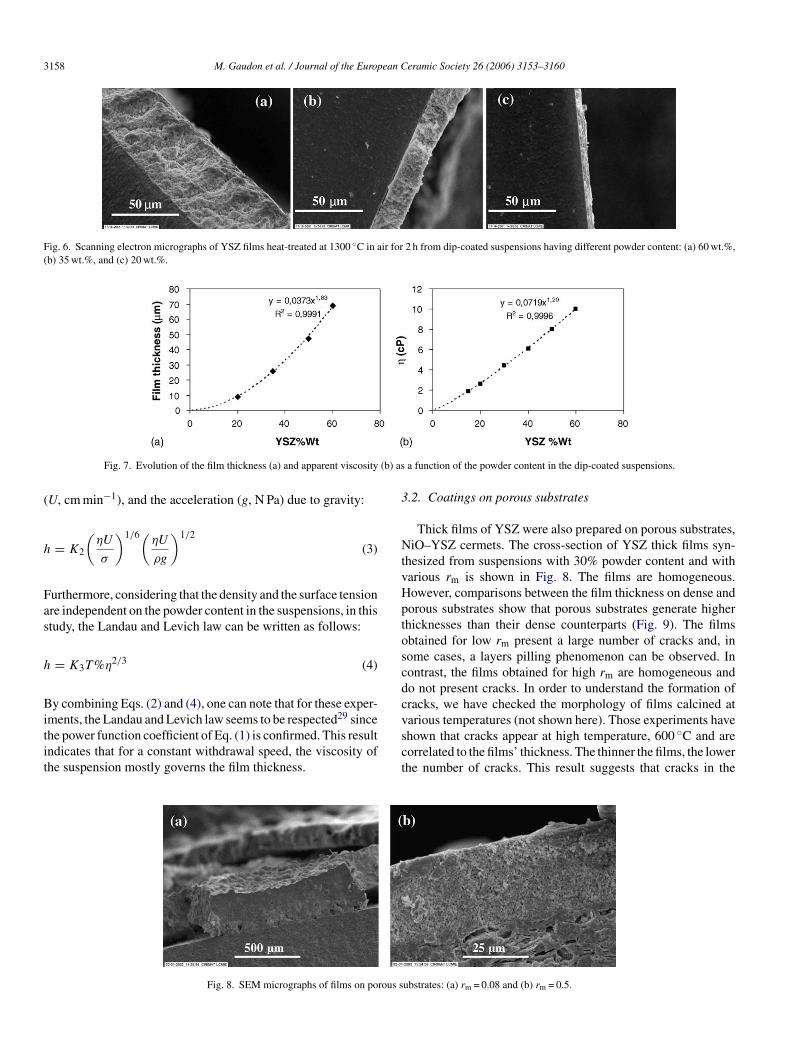
3158 M. Gaudon et al. / Journal of the European Ceramic Society 26 (2006) 3153–3160
Fig. 6. Scanning electron micrographs of YSZ films heat-treated at 1300 ◦C in air for 2 h from dip-coated suspensions having different powder content: (a) 60 wt.%,(b) 35 wt.%, and (c) 20 wt.%.
(b) as
(
h
Fas
h
Bitit
3
NtvHptoscdc
Fig. 7. Evolution of the film thickness (a) and apparent viscosity
U, cm min−1), and the acceleration (g, N Pa) due to gravity:
= K2
(ηU
σ
)1/6(ηU
ρg
)1/2
(3)
urthermore, considering that the density and the surface tensionre independent on the powder content in the suspensions, in thistudy, the Landau and Levich law can be written as follows:
= K3T%η2/3 (4)
y combining Eqs. (2) and (4), one can note that for these exper-
ments, the Landau and Levich law seems to be respected29 sincehe power function coefficient of Eq. (1) is confirmed. This resultndicates that for a constant withdrawal speed, the viscosity ofhe suspension mostly governs the film thickness.vsct
Fig. 8. SEM micrographs of films on porous s
a function of the powder content in the dip-coated suspensions.
.2. Coatings on porous substrates
Thick films of YSZ were also prepared on porous substrates,iO–YSZ cermets. The cross-section of YSZ thick films syn-
hesized from suspensions with 30% powder content and witharious rm is shown in Fig. 8. The films are homogeneous.owever, comparisons between the film thickness on dense andorous substrates show that porous substrates generate higherhicknesses than their dense counterparts (Fig. 9). The filmsbtained for low rm present a large number of cracks and, inome cases, a layers pilling phenomenon can be observed. Inontrast, the films obtained for high rm are homogeneous ando not present cracks. In order to understand the formation ofracks, we have checked the morphology of films calcined at
arious temperatures (not shown here). Those experiments havehown that cracks appear at high temperature, 600 ◦C and areorrelated to the films’ thickness. The thinner the films, the lowerhe number of cracks. This result suggests that cracks in theubstrates: (a) rm = 0.08 and (b) rm = 0.5.

M. Gaudon et al. / Journal of the European
Fa
fiadfigct
tsifdbspr
staihid
4
scpfpdt
mhaTmd
A
A(
R
1
1
1
1
1
1
1
1
1
1
2
2
ig. 9. Evolution of the film thickness as function of the rm ratio for: (a) porousnd (b) dense substrates. Powder content in the suspension of 50 wt.%.
lms are mostly due to the decomposition of organics in thes-prepared films for porous substrates. Indeed, the higher theeposited film thickness, the higher the organic content in thelms (even if the volume fraction of polymeric chains in thereen films decrease with the thickness). That is why cracksannot be suppressed during the heat-treatment step because ofhe high-level of the organic content.
The influence of the powder content in the suspensions, onhe film thickness has been studied. As was the case for denseubstrates, their thickness increases with the powder contentn the suspensions. Nevertheless, this evolution is more rapidor porous substrates and cannot be described by the Lan-au and Levich law. An additional capillarity effect causedy the infiltration of a part of the suspension into the sub-trates pores may explain why thicker films are formed onorous substrate and why the Landau and Levich law is notespected.
The processing technique used in this work enables us toynthesize homogeneous films with a controlled thickness. Thehickness can vary in the range of 8–80 �m. Nevertheless, filmsre still porous even after changing rm and powder contentn the dip-coated suspensions. However, this characteristicas to be optimized in order to be able to use this processn the manufacturing of gas-tight electrolytes for SOFCevices.
. Conclusion
Thick porous YSZ films were deposited on dense and porousubstrates by the dip-coating technology. This technique washosen because it is a simple and low cost technology to coatlanar or three-dimensional surface, which can be further used
or industrial applications. A suspension composed of solvent,owder and polymeric sols was dip-coated on both porous andense substrates. The thickness of the coating was adjusted byhe powder content in the suspensions and the fraction of poly-2
2
Ceramic Society 26 (2006) 3153–3160 3159
eric chains added (rm ratio). The as-synthesized films wereomogeneous and crack-free after heat treatment at 1300 ◦C inir. However, whatever the rm ratio, the sintered films have pores.he thickness obtained so far varies between 8 and 80 �m. Theajor parameters affecting the film’s microstructure are the pow-
er content and the rm ratio.
cknowledgements
This work results from a joint program funded by EDF andDEME. The authors would like to thank Nathalie Thibaud
ADEME) for her support.
eferences
1. Steele, B. C. H., Solid State Ionics, 2000, 134(1/2), 3–20.2. Minh, T. N. Q. and Takahashi, T., Science and Technology of Ceramic
Fuel Cells. Elsevier, Amsterdam, 1995, pp. 165–198 and 233–306.3. Brylewski, T., Namko, M., Maruyama, T. and Prybylski, K., Solid State
Ionics, 2001, 143(2), 131–150.4. Huang, K. Q., Hou, P. Y. and Goodenough, J. B., Solid State Ionics,
2000, 129(1–4), 237–250.5. Stambouli, A. B. and Traversa, E., Renewable Sustainable Energy Rev.,
2002, 6, 433.6. Winkler, W. and Koeppen, J., J. Power Sources, 1996, 61(1/2), 201–
204.7. Minh, N. Q., Proceedings of the 4th International Symposium on Solid
Oxide Fuel Cells, eds. M. Dokiya, M. Yamamoto, H. Tagawa and S. C.Singhal. 1995, pp. 138–145.
8. Barnett, S., Energy, 1990, 15(1), 1–9.9. Simwonis, D., Thulens, H., Dias, F. J., Naoumidis, A. and Stover, D., J.
Mater. Process. Technol., 1999, 92/93, 107–111.0. Charpentier, P., Fragnaud, P., Schleich, D. M. and Gehain, E., Solid State
Ionics, 2000, 135(1–4), 373–380.1. Fuel cell energy, In Seca Annual Meeting, Inc and Versa Power Systems,
Pacific Grove, CA. 2005.2. Carolan, M. F. and Michaels, J. N., Solid State Ionics, 1990, 37(2/3),
189–196.3. Honegger, K., Batawi, E., Spercher, C. and Diethelm, R., Proceedings of
the 5th International Symposium on Solid Oxide Fuel Cells, vol. 97-18,ed. U. Stimming, S. C. Singhal, H. Tagawa and W. Lehnert. Electro-chemical Society, Pennington, NJ, 1997, pp. 321–329.
4. Lang, M., Henne, R., Shaper, S. and Schiller, G., J. Therm. Spray Tech-nol., 1997, 10(4), 618.
5. Minh, N. Q. and Montgomery, K., Proceedings of the 5th InternationalSymposium on Solid Oxide Fuel Cells, vol. 97-18, ed. U. Stimming, S. C.Singhal, H. Tagawa and W. Lehnert. Electrochemical Society, Pennington,NJ, 1997, pp. 153–159.
6. Van Herle, J., Ihringer, R., Cavieres, R. V., Constantin, L. and Bucheli,O., J. Eur. Ceram. Soc., 2001, 21(10/11), 1855–1860.
7. Perednis, D. and Gauckler, L. J., Solid State Ionics, 2004, 166(3/4),229–240.
8. Chen, C. C., Nasrallah, M. M. and Anderson, H. U., Solid State Ionics,1994, 70/71, 101–108.
9. Gaudon, M., Laberty-Robert, Ch., Ansart, F., Stevens, P. and Rousset,A., J. New Mater. Electrochem. Syst., 2002, 5(1), 57–61.
0. Fontaine, M. L., Laberty-Robert, Ch., Ansart, F. and Tailhades, P., J.Solid State Chem., 2004, 177(4/5), 1471–1478.
1. Okubo, T., Takahashi, T., Sadakata, M. and Nagamoto, H., J. Membr.
Sci., 1996, 118, 151–157.2. Okubo, T., Takahashi, T., Nair, B. N., Sadakata, M. and Nagamoto, H.,J. Membr. Sci., 1997, 125, 311–317.
3. Xia, C., Zha, S., Yang, W., Peng, R., Peng, D. and Meng, G., Solid StateIonics, 2000, 133(3/4), 287–294.

3 pean
2
2
2
27. Chartier, T., Merle, D. and Besson, J. L., J. Eur. Ceram. Soc., 1995,
160 M. Gaudon et al. / Journal of the Euro
4. Agrafiotis, G., Tsetsekou, A., Stournavas, C. J., Julbe, A., Dalmazio, L.
and Guizard, C., J. Eur. Ceram. Soc., 2002, 22(1), 15–26.5. Raeder, H., Simon, C., Chartier, T. and Toftegaard, H. L., J. Eur. Ceram.Soc., 1994, 13(6), 485–492.
6. Chartier, T., Hinczewski, C. and Corbel, S., J. Eur. Ceram. Soc., 1999,19(1), 67–74.
22
Ceramic Society 26 (2006) 3153–3160
15(2), 101–108.8. Gaudon, M., Thesis University of Toulouse, 2001, pp. 163–165.9. Landau, L. D. and Levich, V. G., Acta Phys. Chim. USSR, 1942, 17,
42–54.