thermoelastic vibration and damping for circular timoshenko beams
TRANSCRIPT

R.-C. Shieh Structural Dynamics Section,
Transportation Salety Department, Calspan Corporation,
Buffalo, N. Y.
Thermoelastic Vibration and Damping for Circular Timoshenko Beams Within the framework of the theories of coupled linear thermoelasticity and Timoshenko beams, the vibration and thermoelastic damping (with emphasis on the transverse ones) of circular cross-section beams are studied. The governing equations are derived for the case of general mechanical boundary conditions and special thermal boundary conditions that follow the Newton surface heat transfer law. A variational principle governing the eigenfunctions associated with an eigenvalue is formulated. An exact solution, together with the thermoelastic damping coefficient, is obtained for the case of transverse vibrations of a simply supported beam with lateral surfaces thermally insulated and end surfaces kept at constant temperature. Numerical results, together with the discussion for the first two eigenvalues and the thermoelastic damping coefficients, are also presented.
1 Introduction
The analytical study of the thermoelastic vibration and thermoelastic damping mechanism of Timoshenko beams is of interest from both mathematical and physical viewpoints. Existing experimental and analytical results [1-8]1 indicate that material damping in the elastic range of deformation for a wide class of metals can be closely predicted by coupled linear thermoelasticity theory. Through thermomechanical coupling, the stiffness of beam is modified and material damping of thermoelastic nature is introduced. Although this damping is usually small, it has an important effect on the dynamic instability of elastic continuous systems (solid bodies) subjected to nonconservative forces as shown in recent studies [3, 4].
The first systematic study of the thermoelastic damping mechanism for beams based on coupled linear thermoelasticity theory was given by Zener [5, 6] in 1937-1938. Without accounting the effect of longitudinal heat flows (heat currents induced by thermomechanical coupling), he has obtained formulas for the transverse thermoelastic damping coefficients in an infinite series form for both circular and rectangular cross-section beams under adiabatic thermal boundary conditions. A similar study (in connection with the dynamic instability of a nonconservative system) has been made in [3, 4]. Closed-form formulas for the transverse thermoelastic damping coefficients have been obtained in [3] for
1 Numbers in brackets designate References at end of paper. Contributed by the Applied Mechanics Division and presented at the
Applied Mechanics Summer Conference, Rensselaer Polytechnic institute, Troy, N. Y., June 23-25, 1975, of THE AMERICAN SOCIETY OF MECHANICAL ENGINEERS.
Discussion on this paper should be addressed to the Editorial Department, ASME, United Engineering Center, 345 East 47th Street, New York, N.Y. 10017, and will be accepted until August 15, 1975. Discussion received after this date will be returned. Manuscript received by ASME Applied Mechanics Division, July, 1974; final revision, November, 1974. Paper No. 75-APM-16.
rectangular cross-section beams under both adiabatic and isothermal boundary conditions, and in [4] for thin panel (plate) under
•the adiabatic thermal boundary condition. In the present paper, an exact analysis of free vibration and thermoelastic damping is made for circular cross-section beams within the context of the theories of coupled linear thermoelasticity and Timoshenko beams. This means the inclusion of the effects of both transverse and longitudinal heat flows (induced by thermomechanical coupling) in the analysis.
A circular cross-section beam is assumed to be initially unstressed and at rest under a constant absolute temperature T0. The thermal boundary conditions are assumed to follow the Newton surface heat exchange law. General formulation of the vibration boundary-value problem and of a variational principle is given in Section 2 and in the Appendix, respectively. Solutions for the special case of a simply supported beam with the lateral surfaces thermally insulated and end surfaces kept at constant temperature To are given in Section 3. Numerical results together with a discussion for eigenvalues and thermoelastic damping are presented in Section 4.
2 F o r m u l a t i o n of B o u n d a r y - V a l u e P r o b l e m Consider a circular cross-section elastic beam of radius a and
length /. Let t be the time, x the axial coordinate, and y the thickness coordinate of the beam, Fig. 1. Let the beam vibrate transversely in the xy -plane and denote the displacement components in the x and y-directions by ux and uy, respectively. Assuming that the Poisson ratio is zero (as in the elementary or Timoshenko beam theory), and a plane cross section originally normal to the undeformed centroidal axis (i.e., x-axis) remains plane (but need not remain normal to the deformed axis) after deformation, the displacement components may be written as
ux = u(x, t) + yy(x,t),
= v{x,t) (1)
Journal of Applied Mechanics JUNE 1975 / 405 Copyright © 1975 by ASME
Downloaded From: http://appliedmechanics.asmedigitalcollection.asme.org/ on 08/27/2013 Terms of Use: http://asme.org/terms

1
I
• 1
.
X
A i
i •*Tfl>
.
V
) 1 1
Fig. 1 Coordinate systems Fig. 2 Free-body diagram of beam element
Here u represents the axial displacement of the beam centroidal axis and y the angular rotation of a generic beam cross section in the xy-plane.
Let o-j and rxy be the axial and shear stresses, respectively. Within the framework of linear thermoelasticity theory, these stress components are related to the displacement components by
\dy 3xJ \ r SxJ (26)
where E is Young modulus, G the shear modulus, a the coefficient of linear thermal expansion, and T the temperature change from the uniform initial absolute temperature To of the beam.2 Let N (x, t) be the axial force, V (x, t) the shear force, and M (x, t) the bending moment at section x. They are related to the stresses and thus functions u, v, y, and T by
N = f vxdA = EA^ - NT
JA * dX L
= ^KAT„dA =KAGA(Y + g )
M - \ oxydA = EI^ - MT J A O X
(3)
(4)
(5)
Here, KA = 10/9 is the shear correction factor, A is the cross-sectional area, / is the second moment of inertia about the y-axis, and
N7 = Ea I TdA, MT = Ea I yTdA J& ^A
(6)
Let p be the mass density, m (x, t) and / (x, t) the applied couple and transverse force per unit length of the beam and the dots indicate material time derivatives. With reference to Fig. 2 and also use of equations (3)-(5), the following equations are established from principles of balance of linear and angular momentums:
SN 8x
pAVi = EA—-j - - r -T dXd &X
5X + f - pA'v = KAGA
(dy
\dx dx'
pAu - 0 (7a)
^ - pA'v + f = 0 (76)
2 Since the temperature change T caused by thermomechanical coupling is usually small, the material constants E, G, a will be assumed to be independent of T.
—— - V + m - ply = EI dx H dx'
dMT
dX
for a free vibration • ( * • £ )
/ = m = 0
ply + 0 (7c)
(8)
For the mechanical boundary conditions, one specifies at x = 0 and / (i) either JV or u, (ii).M or y, and (iii) V or u. If the variations of u, v, and y are denoted by Su, 5v, and dy which vanish at the boundaries where u, v, and y are prescribed, then the boundary conditions may be conveniently expressed as (cf., equations (3)-(5))
(EAJ! - NT)du = 0 at x = 0 ,1
KAGA ( y + | ^ 6« = 0 at x = 0 ,1
[EI^ - MT W = 0 at x = 0,1
(9a)
(96)
(9c)
The temperature change T is governed by the coupled heat-conduction equation [9] (specialized for beams) as
\_r dr\ Br /
1 32T 32T H o —T5 + rl 8i|r Sx'
( ait
+ pCET
+ EaT\Tx + r c o s * S ) 0 (10)
where k is the coefficient of heat conductivity, CE is the specific heat at constant deformation, and (r, \p, x) are the cylindrical coordinates. It should be pointed out that the temperature distribution resulting from the solution of equation (10) must be such that it is consistent with the assumption of plane beam vibrations. For the thermal boundary conditions, they are assumed to be governed by the Newton surface heat exchange law
dr
^ ± KLT = dX L
0 at r = a
0 at x -G) (lia)
(116)
where Kn (n = T, L) are the coefficients of surface heat conductivity with Kn = 0 corresponding to the thermally insulated boundary
406 / JUNE 1975 Transactions of the ASME
Downloaded From: http://appliedmechanics.asmedigitalcollection.asme.org/ on 08/27/2013 Terms of Use: http://asme.org/terms

condition and T = 0 the isothermal boundary condition. Equations (7)-(9), together with equations (10) and (11 a, b), constitute a coupled thermoelastic vibration boundary-value problem for circular cross-section Timoshenko beam. In solving the thermoelastic vibration boundary problem, the following continuity conditions and physical consideration must also be taken into account:
T(r,ip,x,t) = T(r,ip + 2mr,x,t) (n = 1 , 2 . . .)
l im T{r, ip, x, t) = finite (12)
For the solution of the thermoelastic vibration boundary-value problem, the expressions
u = u(x)eKt, v = v(x)eAt
y{x)eAt, T = T(r,ip,x)eAt y (13)
are substituted into equations (7)-(12). The resulting equations, which are called eigenvalue equations, govern the associated eigenvalue problem in A and u, v, y, and T. This eigenvalue problem is then solved to yield infinitely many eigenvalues A = An (n = 1, 2, . . . ) and the associated eigenfunctions un, vn, yn, and Tn. A variational principle in terms of these eigenfunctions is formulated in the Appendix.
In the remainder of this paper, the eigensolution and thermoelastic damping coefficients for a simply supported beam with lateral surfaces thermally insulated and end surfaces kept at constant temperature are considered.
3 Solution for the Case of Simply Supported Beam With La te ra l Surfaces Thermal ly Insulated and End Surfaces Kept a t Constant Tempera tu re
The boundary-value problem for this case is governed by the differential equations (7) and (10), the boundary conditions
w(0,1) = u{l, t) = 0
r8!
(14a)
v = 0, M = EJV- - MT = 0 at x = 0,1 (146) ox
ST/or = 0 at r = a
T = 0 at x = 0,1
(15a)
(156)
and the side conditions (12). The longitudinal and transverse vibrations (u and v) can be uncoupled by the following procedure.
Integration of equations (10) and (156) over cross-sectional area leads to
, 9 ^ •TxT
pcENt = Eid>T«Afx
NT(x, t) = 0 at x = 0,1
(16a)
(166)
where conditions (12) and (15d) have been used. Equations (7a), (14a), and (16 a, 6) govern the eigenvalue problem'for longitudinal vibrations of the beam. It is seen that the longitudinal vibrations are uncoupled from the transverse ones (although converse may not be true). Therefore, if no initial longitudinal disturbance is imposed on the system at t = 0, i.e., NT(X, 0) = u(x, 0) = u(x, 0) = 0, it is apparent that the solution of equations (7a), (14a), and (16 a, 6) is
NT{x, t) = u{x, t) = 0 (17)
Thus, under the assumption of zero initial longitudinal disturbances (because only transverse vibrations are concerned here), the equations governing the exact transverse vibration of the beam in question are equations (7 6, e), (10) (with u = 0), (12), (146), and (15 a, b). These equations are then nondimensionalized according to
* x J'
R = a aT &
(18a)
Journal of Applied Mechanics
t = c V , c = a/l, (3 = Ea2T0/pcE, T = W 0T 0
s = KAGAf/EI (18a) {Cont.)
where /3 is the thermomechanical coupling parameter, s is the shear stiffness parameter, and
w0 = (EI/pAl^, T 0 = pcBa2/k (186)
are, respectively, the reference frequency and relaxation time of thermal diffusion. Upon substitution of
v = W{i)eu, ~T - 9{R,ip,£,)en
y = cipU)eM (19)
into these nondimensionalized equations, there are obtained
s<p' + sW" - X2W = 0, (20a)
~ - I "STRl c o s $dRdrl> = 0 (206) n Jo Jo d ?
W(0) = W(l) = 0 (21a)
<p'(0) = cp'(l) = 0 (216)
" (s +^T"V~ sW
and
R dR \ 3RJ
+ | s 0 - *T0 = P*TRtp'(li) cos ip (22)
9(R, ip, 0) = 8{R, ip,l) = 0
30 dR ( 1 , <P, 5) = 0
(23a)
(236)
(23c)
9{R,ip,£) = 6{R,ip + 2WTT, £)(w = 1,2, . . .) (23d)
l im 6(R, tp, 0 = finite
Here, primes indicate differentiations of a function with its argument and where the thermal boundary conditions (23a) have been used in obtaining equations (216).
We seek a solution of these equations in the form
<p = A„ cos mr£, W = Bn s in wnt,
8 = Xn(R,ip) s in W7r|(w = 1, 2 . . . ; An, Bn = cons ts )
(24a)
which satisfy all boundary conditions at both ends of the beam. Consequently, the remaining equations to be satisfied are equations (20), (22), and (236)-(23d). Thus equations (20a) and (24a) immediately give
B„ = -nusAn/[\2 + s{nir)2] (246)
After substituting equations (24a) into equations (22), (23c), and (23d), the resulting equations are solved by using the standard separation of variables technique to yield
X„{R,ip) = £ Jm{ii±nR)(Am cos mip
_!_ r> • ,\ , Anp\TmrR cos i[> , „ . . + Bm s in mtp) + —a —j 1 (24c)
in which Jm is the mth order Bessel function of first kind, Amn and Bmn are constants and
Hn = [XT + (WCTT)2]1/2 (24d)
JUNE 1975 / 4 0 7
Downloaded From: http://appliedmechanics.asmedigitalcollection.asme.org/ on 08/27/2013 Terms of Use: http://asme.org/terms

The solution, equation (24c), in view of equations (23b) and (24a), becomes
(24e)
Substitution of equations (24 a, b, e) into equation (206) and observing that for nontrivial solution, An ^ 0 yield the characteristic equation
M 4 ( l + fA) + (XMCTT)V4 + X2 /[ l + X2/s(w7T)2] = 0 (25)
where n = 1, 2 , . . . , and
fA{\T, nc,P) = — j l + i V-„J\ 'U'M„)J
= TT^I1 - T T M 1 - Jo(iMB)/J2(iM„)]} (26)
The roots X = Xr(r = 1, 2, . . . ) of the characteristic equation (25) are the eigenvalues of the system. Finally, upon substitution of equations (24 6, e) into equations (24a), we obtain the eigenfunc-tions
<M£) = A„ cos WTT£,
W{£) = -A„snir s in «7r£/[X2 + s(w7r)2] (27a)
8(R, >P, 0
= A„p\TniT I" _ J^ijinR)
M7~L ili„Ji'(ilJ-„).
(X = Xr; r = 1 ,2 ,
cos $ s in «7r£. (276)
Solution Corresponding to Bernoulli-Euler Beam Theory. It is well known that the Bernoulli-Euler beam theory is a special case of Timoshenko beam theory in which both rotatory inertia and shear deformation effects are neglected. Mathematically, the governing equations based on the former can be obtained by a limiting process from those of the latter (equations (76)-(9c)) in which the shear stiffness KAGA (or s in equations (20a, 6)) is made to approach infinity and rotary inertia force ply (or equivalently, parameter c2 in equation (206)) to approach zero. Therefore, the consistent coupled thermoelastic Bernoulli-Euler beam equations and the corresponding solution can be obtained, respectively, from equations (20)-(23) and equations (25)-(27) by letting s - • <» and c —• 0. Thus the heat-conduction equation now is given by equation (22) with the longitudinal heat flow gradient term c2320/d|2
omitted and, correspondingly, the two thermal end conditions, equations (23a), must be ignored; also the first two of equations (20) now are combined to give
-W (28a)
WlY + X2W + 4_ f2* r 1 8 ir J„ J„ "9 72 R2 cos i[> dRdip = 0 (286)
The corresponding solution is (cf., equations (25)-(27))
W{£) = A„* s in rnii, ( A „ * =
• 9(R, ip, £)
A. nit'
n - 1,2 . . . ) (29. a)
= -A„*{m)'1 (i R Jt(ijA~TR)
«/XrJ'1'(«/xf)
in which X is a root of the characteristic equation
(WTT)4[1 + / 0 ( X T , /3)] + X2 = 0
cos tp s in rmi, (296)
(30)
and f0 is the corresponding thermomechanical coupling function given by
10"
10-5
,n-6 l,
- - ' •
/ -Re t A 2)
/ y
• • —
—
i r
'l>
I m U , !
bj * - " * P 1 -?•*
' rfm A2>
j \
a
~:_:.
= 0.00
= 0.25 (6.35 mm)
411*
1I2
LENGTHS - RADIUS RATIO 1/c = 1 la.
Fig. 3 Damping and frequency of the first two eigenvalues \, and X2 for the aluminum shaft
/ O ( * T , (3) = (3 1 +
4 T h e r m o e l a s t i c D a m p i n g , N u m e r i c a l R e s u l t s and D i s c u s s i o n
The first two eigenvalues Xi and X2 (Im (Xi) < Im (X2) < Im (X3) . . . ) of the system satisfying equation (25) are plotted in Fig. 3 for the aluminum beam of radius a = 0.25 in. (6.35 mm). The values of /? and T for this beam at absolute room temperature To = 537 deg R (298K) are computed as /? = 0.005 and r = 1.18 X 10⁶c2. Within the range of slenderness ratio 1/c = l/a shown in Fig. 3, the absolute values of the damping (real) part v of X (v = Re (X) < 0) increase as 1/c increases while the values of frequency (imaginary) part w = Im (X) of X are almost independent of 1/c for 1/c > 10. The sharp decrease in eigenfrequencies wn = Im (X„) (n = 1, 2) as 1/c approaches 0 from 1/c = 10 is primarily due to the effect of shear deformation and rotatory inertia rather than due to that of thermomechanical coupling; that is, the main effect of thermomechanical coupling on a dynamic system is in introducing damping into the system.
Thermoelastic Damping. The thermomechanical coupling function fA given by equation (26) represents the effect of thermomechanical coupling on the dynamic system. The real part of this function characterizes the stiffening effect while the imaginary part
gA(i>T,o>T,nc,P) = Im {fA(\T,nc,P)} (32)
characterizes the damping effect, and is the thermoelastic damping coefficient for simply supported circular cross-section Timoshenko beam with the mixed boundary conditions (15 a, 6).
Thus the thermoelastic damping coefficient is a function of the damping parameter VT, frequency parameter cor = pcga2Q/fe(Q = woo) = real frequency), wavelength parameter f = 1/rac and thermomechanical coupling parameter /J. The limiting case
g0(vT, COT, p) = Im {/„(XT, /3)} (33)
of gA as nc approaches 0, i.e., wavelength parameter f approaches infinity is the corresponding damping coefficient for Bernoulli-Euler beam. It should be noted that Zener has obtained the thermoelastic damping coefficient corresponding to g0 in a series form of which the first term under v = 0 (i.e., X = io>; u>2 > 0) is [6]
408 / JUNE 1975 Transactions of the ASME
Downloaded From: http://appliedmechanics.asmedigitalcollection.asme.org/ on 08/27/2013 Terms of Use: http://asme.org/terms
. .* 10'
< 10'
10"
1
• 2
• 3
// , /' /
-J^
/ / /
V -
/
/ :
/ /
/
A : : o>
* +<f \ , / Af/
# /
&T-/-/
/ /
/ /
/
-// / /
/
/ /
y / / /
-y /
2 ' .+-
TL
/ /
/ /
/• /
<>?/ / /
4/ ----?&
/ 'z
/* /
/ y_ / ' /
/
/ /:. /
J /
;*
r
- M - " " ^ -
S^7 ^
XN\ / S.
7 ^ -
/ /
/ V
\ - • -
/
K ^s * ^ -
^ ^ - \ ss b.^
1
-?S
\ \
:^_ \ \ ^ s \
^O. \ ^ x \ \
^ N g z / / 3 , « r . CURVE
(ZENER'S FORMULA) L_L.
1 1 t t l ' 111 ujf- CURVE
—^—
\
V "* " \
J^x • S C v ^
\
• -
05 " ^ J r
W
/>CEa.* FREQUENCY PARAMETER u>T =
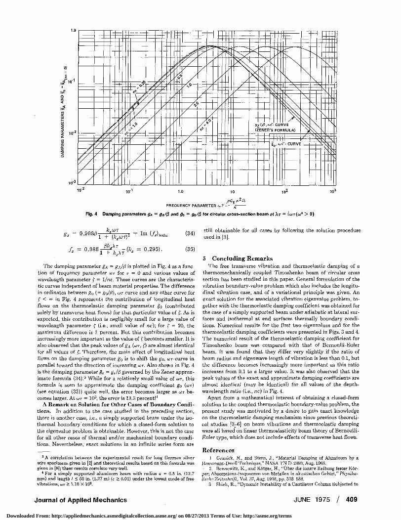
Fig. 4 Damping parameters §A - g^/ft and g0 = gt,/f} for circular cross-section beam at AT = J<I)T(CO2 > 0)
&,0JT
*' = °-988^l +\k.oD* = Im (/^=< Pk^XT
f, = 0.988 i + ' f e x r ^ ' = 0>295)-
(34)
(35)
The damping parameter gA = gA/fi is plotted in Fig. 4 as a function of frequency parameter COT for v = 0 and various values of wavelength parameter f = 1/nc. These curves are the characteristic curves independent of beam material properties. The difference in ordinates between g0 (= go/0), cor curve and any other curve for f < <° in Fig. 4 represents the contribution of longitudinal heat flows on the thermoelastic damping parameter g0 (contributed solely by transverse heat flows) for that particular value of f. As is expected, this contribution is negligibly small for a large value of wavelength parameter f (i.e., small value of nc); for f = 20, the maximum difference is 1 percent. But this contribution becomes increasingly more important as the value of f becomes smaller. It is also observed that the peak values of gA (MT, f) are almost identical for all values of f. Therefore, the main effect of longitudinal heat flows on the damping parameter ga is to shift the go, coT-curve in parallel toward the direction of increasing COT. Also shown in Fig. 4 is the damping parameter gz = gz/fj governed by the Zener approximate formula (34).3 While for a relatively small value of COT, this formula is seen to approximate the damping coefficient go (COT) (see equation (33)) quite well, the error becomes larger as COT becomes larger. At COT = 103, the error is 13.3 percent!4
A Remark on Solution for Other Cases of Boundary Conditions. In addition to the case studied in the preceding section, there is another case, i.e., a simply supported beam under the isothermal boundary conditions for which a closed-form solution to the eigenvalue problem is obtainable. However, this is not the case for all other cases of thermal and/or mechanical boundary conditions. Nevertheless, exact solutions in an infinite series form are
3 A correlation between the experimental result for long German silver wire specimens given in [2] and theoretical results based on this formula was given in [8]; these results correlate very well.
4 For a simply supported aluminum beam with radius a = 0.5 in. (12.7 mm) and length ( < 50 in. (1.27 m) (c > 0.01) under the lowest mode of free vibrations, COT > 1.16 X 10³.
still obtainable for all cases by following the solution procedure used in [3].
5 Concluding Remarks The free transverse vibration and thermoelastic damping of a
thermomechanically coupled Timoshenko beam of circular cross section has been studied in this paper. General formulation of the vibration boundary-value problem which also includes the longitudinal vibration case, and of a variational principle was given. An exact solution for the associated vibration eigenvalue problem, together with the thermoelastic damping coefficient was obtained for the case of a simply supported beam under adiabatic at lateral surfaces and isothermal at end surfaces thermally boundary conditions. Numerical results for the first two eigenvalues and for the thermoelastic damping coefficients were presented in Figs. 3 and 4. The numerical result of the thermoelastic damping coefficient for Timoshenko beam was compared with that of Bernoulli-Euler beam. It was found that they differ very slightly if the ratio of beam radius and eigenwave length of vibration is less than 0.1, but the difference becomes increasingly more important as this ratio increases from 0.1 to a larger value. It was also observed that the peak values of the exact and approximate damping coefficients are almost identical (may be identical) for all values of the depth-wavelength ratio (i.e., nc) in Fig. 4.
Apart from a mathematical interest of obtaining a closed-form solution to the coupled thermoelastic boundary-value problem, the present study was motivated by a desire to gain exact knowledge on the thermoelastic damping mechanism since previous theoretical studies [3-6] on beam vibrations and thermoelastic damping were all based on linear thermoelasticity beam theory of Bernoulli-Euler type, which does not include effects of transverse heat flows.
References 1 Granick, N., and Stern, J., "Material Damping of Aluminum by a
Reasonant-Dwell Technique," NASA TN D-2893, Aug. 1965. 2 Bennewitz, K., and Kotger, H., "Uber die innere Reibung fester Kor-
per; Absorptions-frequenzen von Metallen in akustischen Gebiet," Physika-lische Zeitschrift, Vol. 37, Aug. 1936, pp. 578-588.
3 Shieh, R., "Dynamic Instability of a Cantilever Column Subjected to
Journal of Applied Mechanics JUNE 1975 / 409
Downloaded From: http://appliedmechanics.asmedigitalcollection.asme.org/ on 08/27/2013 Terms of Use: http://asme.org/terms

a Follower Force Including Thermomechanicai Coupling Effect," JOURNAL OF APPLIED MECHANICS, Vol. 38, No. 4, TRANS. ASME, Vol. 93, Series E, Dec. 1971, pp. 839-846.
4 Shieh, R., "Thermoelastic Damping and Its Effect on Flutter of Stressed Panels Situated in a Supersonic Airflow," NASA TN D-6448, Nov. 1971.
5 Zener, C, "Theory of Internal Friction in Reeds," Physical Review Vol. 52,1937, pp. 230-235.
6 Zener, C., "General Theory of Thermoelastic Internal Friction," Physical Review, Vol. 53,1938, pp. 90-99.
7 Zener, C, Otis, W., and Nuckolls, R., "Internal Friction in Solids, III. Experimental Demonstration of Thermoelastic Internal Friction," Physical Review, Vol. 53,1938, pp. 100-101.
8 Lazan, B., Damping of Materials and Members in Structural Mechanics, Pergamon Press, N. Y., 1968.
9 Boley, B., and Weiner, J., Theory of Thermal Stresses, Wiley, N. Y., 1960, p. 31 and Chapters 10 and 13.
10 Mikhlin, S., Approximate Methods for Solution of Differential and Integral Equations, American Elsevier Publication Co., N. Y., 1967.
APPENDIX A Variational Principle. As is the standard way of formulating a variational principle, the eigenvalue equations corresponding to equations (7a), (76), (7c) and (10) are first multiplied by &u, SO, By and oT/Ta, respectively. The first three equations are then integrated over x = 0 to / and last one over the volume. Finally, adding these equations together and making use of the eigenvalue boundary conditions corresponding to equations (9 a, b, c) and (11 a, b) in the last resulting equation, yields to the variational equation SV = 0, where
V = - [\pAK2u2 + EAu'2 - 2NTu' + pAk2v2
+ KAGA(Y + v')2 + pIA2y2 + Ely'2 - 2MTr']dx - U (36)
and whe re
and
+ £2*T*}dAdx + ±jlf2'j2rT2(a,t,x)adil,dX
+ f ^r[r2(r,il>,T) + T\r,i>,V)}dA (37)
In arriving at equation (36), the results of equations (12) after substitution of equations (13) have been used. If one defines a function to be admissible if it satisfies the kinematical (geometrical) boundary conditions,5 one may state the following variational principle:
Of all admissible functions u, u, y, and T, the set of eigenfunc-tions associated with the eigenvalue A is characterized by the stationary value of V, i.e., 6V = 0, where V is given by equation (36).
It is a simple matter to extend this principle to include the case in which external forces are present in the system. This variational principle is especially useful in an approximate analysis similar to that of Ritz [10] by choosing a complete set of trail functions for u, v, y, and f.
8 Here the zero temperature change condition is also regarded as a kinematical boundary condition.
410 / JUNE 1975 Transactions of the ASME
Downloaded From: http://appliedmechanics.asmedigitalcollection.asme.org/ on 08/27/2013 Terms of Use: http://asme.org/terms