thermo-mechanical properties of siliconnitrate ceramic...
TRANSCRIPT
Thermo-mechanical properties of siliconnitrate ceramic composites……….
978-93-82163-46-6 All rights reserved 166
THERMO-MECHANICAL PROPERTIES OF SILICONNITRATE CERAMIC COMPOSITES
FOR FUSED DEPOSITION MODELING
S.Sreenivasulua and A chennakeshava Reddyb a Asst.professor in Department of Mechanical
Engineering,RGMCET,Nandyal- 518501, bProfessor in Department of Mechanical Engineering, JNTUCE, Hyderabad
Abstract: This paper presents an investigation of thermal and mechanical properties of new metal-particle filled silicon nitrate composites for applications in Fused Deposition Modeling rapid prototyping process. Test samples of Iron/ silicon nitrate and Copper/ silicon nitrate composites involving metal content up to 40% by volume have been made by controlled centrifugal mixing, thermally compounded through a single-screw extruder and compression moulding. Dynamic Mechanical Analysis (DMA) techniques were used in order to characterize viscoelastic properties of these newly developed composites materials for use in Fused Deposition Modeling process. It has been shown that significant improvements of Si3N4 thermal and mechanical properties due to incorporation of metallic fillers can potentially promote processing of high performance and functional prototypes on the existing FDM platform for a wide range of applications. Sample prototypes from the new composite materials have been successfully made and tested. KEYWORDS: Fusion deposition modeling, composite materials, thermal properties, filements
Corresponding author: e-mail:[email protected]
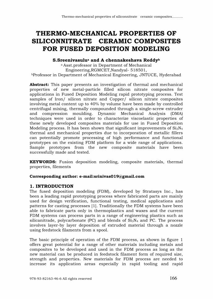
1. INTRODUCTION The fused deposition modeling (FDM), developed by Stratasys Inc., has been a leading rapid prototyping process where fabricated parts are mainly used for design verification, functional testing, medical applications and patterns for casting processes [1]. Traditionally the FDM systems have been able to fabricate parts only in thermoplastics and waxes and the current FDM systems can process parts in a range of engineering plastics such as silicanitrade, polycarbonate (PC) and blends of Si3N4 and PC. The process involves layer-by layer deposition of extruded material through a nozzle using feedstock filaments from a spool. The basic principle of operation of the FDM process, as shown in figure 1 offers great potential for a range of other materials including metals and composites to be developed and used in the FDM process as long as the new material can be produced in feedstock filament form of required size, strength and properties. New materials for FDM process are needed to increase its application areas especially in rapid tooling and rapid
International Conference on Advanced Materials and manufacturing Technologies (AMMT)
December 18-20, 2014
JNTUH College of Engineering Hyderabad
Paramount Publishing House, Hyderabad 167
manufacturing. There has been very limited amount of research conducted over the years to develop new materials for the FDM process. Researchers at Rutgers University were the first to develop some new metallic and ceramic based materials for the FDM process for rapid fabrication of functional components with improved mechanical properties [2, 3]. They have used the process to fabricate functional parts in a variety of materials such as silicon nitride, aluminum oxide, hydroxyapatite, lead–zirconium–titanate (PZT) and lead–magnesium niobate (PMN) as well as stainless steel for structural and bioceramic applications.
Figure 1: Schematic of Stratasys FDM process.
They created such components on the FDM system using metal/ceramics powders mixed with organic binder system. The properties of the mixed feedstock filament meet the flexibility, stiffness, and viscosity required for successful FDM processing. But the fabricated green parts need to undergo further processing to remove the organic binder and are subjected to sintering to achieve densification. Sintered part may be infiltrated with other type of metal materials. Based on the FDM principle, researchers at Rutgers have also developed a separate process of fused deposition of multi-materials, where up to four different materials can be deposited for applications in multi-material actuators [4].Work has also been done to develop new thermoplastic composites or to improve the properties of the existing thermoplastics for the FDM process. GrayIv et al. [5] developed composites of thermotropic liquid crystalline ceramics (TLCP) in polypropylene (PP) matrix for the FDM process with the aim of enhancing the tensile properties and the functionality of the FDM made prototypes. They used dual extrusion process to develop the filaments and investigated the effects of various factors on the tensile properties and morphology of the prototypes. Zhong et al. [6] have investigated the development of short fiber reinforced ABS composites to improve the strength of the ABS filament for FDM processing. They also studied the effects of plasticizer and compatibilizer to further enhance other properties. Shofner et al. [7] have developed nanofibre-reinforced based composites for Fused Deposition Modeling process combining single-walled carbon nanotubes with ABS materials. They used nanofibres up to 10% by weight and achieved an average of around 40% increase in tensile strength in the composites. A major focus of research in material development for FDM has been in the area of tissue engineering scaffolds. Attempts have been made to develop
Thermo-mechanical properties of siliconnitrate ceramic composites……….
978-93-82163-46-6 All rights reserved 168
biocompatible materials for processing in DM for fabrication of scaffolds for tissue engineering applications.
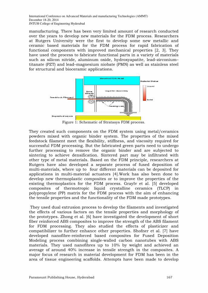
Table 1: Metal/ceramic composites constituents
Type of matrix Type of filler
material
Size of
Filler (µ m)
Filler loading
(%)
Designation of
composite
silicon nitrate silicon nitrate silicon nitrate silicon nitrate silicon nitrate silicon nitrate silicon nitrate silicon nitrate silicon nitrate silicon nitrate silicon nitrate silicon nitrate silicon nitrate silicon nitrate silicon nitrate
Cu Cu Cu Cu Cu Cu Cu Cu Cu Cu Fe Fe Fe Fe Fe
10 10 10 10 10 45 45 45 45 45 45 45 45 45 45
5 10 20 30 40 5 10 20 30 40 5 10 20 30 40
A1 A2 A3 A4 A5 B1 B2 B3 B4 B5 C1 C2 C3 C4 C5
Researchers at the University of Singapore have processed PCL and several composites (PCL/HA, PCL/TCP etc.) on the FDM systems [8]. Endres et al. [9] and Rai et al. [10] have used PCL and CaP composite scaffolds developed by FDM for bone tissue engineering. Woodfield et al. [11] have used FDM process for making scaffolds made of PEGT/PBT composites with a range of mechanical properties for articular cartilage application. Kalita et al. [12] have developed particulate-reinforced ceramic–ceramic composites using polypropylene (PP) ceramic and tricalcium phosphate (TCP) ceramic for scaffolds fabrication on the FDM system. From published literature, it is noted that, while some efforts have been made to improve the existing FDM ceramics or to develop new materials for tissue engineering applications using the FDM process, very little research has been directed to develop materials for other engineering applications such as tooling and functional parts with enhanced properties. For tooling and functional applications, strong metal based composites are needed to be processed by the FDM process with desirable, mechanical and thermal properties. This paper presents the development and characterization of metal-filled FDM-grade composite materials for direct FDM processing without the need of binder removal or infiltration process. The aim is to develop the new composites with desirable thermo-mechanical properties with direct rapid tooling for injection moulding applications. This research focuses on developing a proper formulation and mixture of constituent materials for obtaining certain properties of the
International Conference on Advanced Materials and manufacturing Technologies (AMMT)
December 18-20, 2014
JNTUH College of Engineering Hyderabad
Paramount Publishing House, Hyderabad 169
composite material so that they can be produced in filament form for use in the Fused Deposition Modeling process. The success of this unique work depends upon careful selection of proportion of constituent materials and fillers to result in the desired properties of the composite material. The main outcome of this major breakthrough is the manufacture of a strong, flexible and spoolable feed stock filaments made by extrusion from the composite materials for use in the existing FDM system without any hardware or software modification. In this investigation, three main types of constituent materials are used to develop the new composite materials. The first material,used as the matrix, is the silica nitrate (Si3N4) thermoplastic, which is the most commonly used material used in the FDM systems. The Si3N4 has good mechanical properties and fluidity, desirable flexibility and stiffness, which are required for successful FDM processing. The other constituent materials are the commercial grade iron powder, and copper powder, which have properties of high strength, toughness and conductivity. Two separate composites are prepared, one with iron powder mixed in Si3N4 matrix and the other with copper powder mixed in Si3N4 matrix, which are then used to make the feedstock material. The required properties for the matrix material are appropriate stiffness,flow,flexibility,strength and modulus. In addition to forming the part with the layers deposited, the filament also acts as a piston at the entrance of the liquefier head in FDM machine, forcing the molten material out of the nozzle. In addition to forming the part with the layers deposited, the filament also acts as a piston at the entrance of liquefier head ,forcing the molten metal out of the nozzle. Filaments require a high stiffness and lower melt viscosity to a useable level. Due to the high metal powder loading in the ceramic matrix, the viscosity of the composite is increased and dispersion gets worse. Therefore additives, such as surfactants and plasticisers are necessary to this composite material formulation
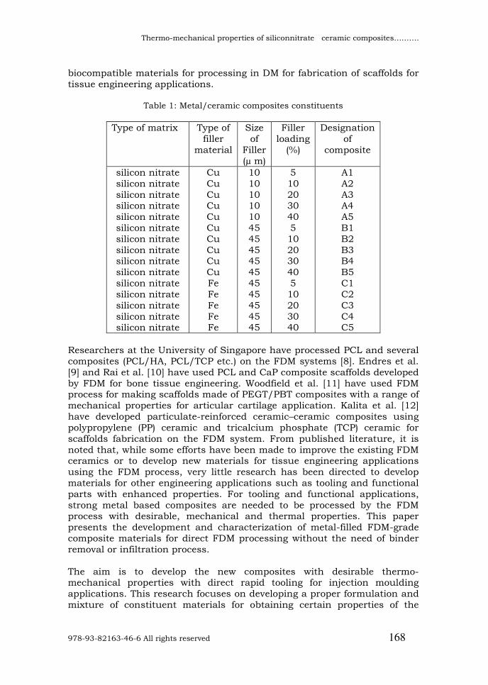
2. MATERIALS AND METHODS In this experiment the silicon nitrate is used as a matrix material, the metal used for filler material is copper powder and iron powder of size10µm&45µm.Table 1 represent the Metal/ceramic composites constituents,The filler material is loaded in 5%, 10%, 20%, 30% and 40%. Figure 2 shows the representation of Si3N4& metal particles.
Figure 2: Representing silica nitrate and copper and iron particles
2.1. Preparation of Metal/ Si3N4 Composites
Thermo-mechanical properties of siliconnitrate ceramic composites……….
978-93-82163-46-6 All rights reserved 170
To develop the new metal–ceramic composites, mixtures of iron powder with Si3N4powder and copper powder with Si3N4 powder, as representative metal–ceramic elements, were chosen with varying volume fractions of metal powder with the aim of producing appropriate feed stock filament for FDM processing. The main reasons for selection of iron and copper powders as short fiber fillers were their reasonably good mechanical and thermal properties as well as their capabilities of mixing and surface bonding with ceramics. The metal powders were purchased from Sigma–Aldrich in Australia. The purity of both metal powders was 99.7% with one particle size, 45 µm, was used for iron and two particle sizes, 10µm and 45µm, were used for copper for this investigation. The specific gravity of iron powder was 7.88 gr/cm3 and the shape of the powder particles was irregular for iron and spherical for copper. composite designations and the constituents used for each composite investigated in this study. The Si3N4 is prepared by heating powdered silicon between 1300 °C and 1400 °C in an atmosphere of nitrogen. The specific gravity of Si3N4 was 3.2 gr/cm3. To produce Si3N4 micro particles, sufficient amount of P400 filament was first pelletized on a mechanical chopper. Then the Si3N4 pellets were ground to fine powders using the cryogenic grinding technique. The machine used for this purpose was a SORVALL OMNI high speed grinder operating at temperatures well below glass-transition temperature of the ceramic. During this process, the Si3N4 pellets were frozen by the surrounding liquid nitrogen which resulted in lower molecular energy of the pellets. Simultaneously, high speed rotation of stainless steel blades within the chamber containing the Si3N4 pellets could easily break them below the glass-transition temperature. This process does not damage or alter chemical composition of material making it a very efficient ceramic powder production technique In order to achieve a homogeneous mixture with higher packing factor when mixed with metal particles an Si3N4/metal particle size ratio of approximately 10–1 or over was required [13]. Therefore, the Si3N4 pellets were ground to a particle size of approximately 450–500 µm. To get the same size for Si3N4 particles, grinding process was done in three time-interval of 5 min between which the particles were sieved to the appropriate size. This helped to screen the particles of different size range than 450–500 µm. The composite mixtures were then loaded in a multi-variable speed homogenizer to achieve maximum possible homogeneous-distribution of metal powder in Si3N4 matrix. Scanning electron microscopy (SEM) images of the prepared samples were analyzed to make sure a homogeneous matrix of metal–ceramic composite is achieved. At the end, a very small percentage by volume of a surfactant was added to the mixtures. According to the previous studies carried out at Swinburne regarding composition of metal and plastic particulates [14], the addition of surfactant increased homogeneous dispersion of metal particles in ceramic matrix. The
International Conference on Advanced Materials and manufacturing Technologies (AMMT)
December 18-20, 2014
JNTUH College of Engineering Hyderabad
Paramount Publishing House, Hyderabad 171
surfactant powder is coated on the metal particles, which reduces the high free energy surfaces of the metal fillers, and that in turn results in much lower interfacial tension between composite particles in melt stage. The coated metal particles give good link to lower free energy surfaces of ceramic particles.
2.2. Fabrication of FDM filaments In order to create a part on the FDM system using the new composite material, a certain amount of this composite is required to create the filaments for FDM machine. This amount of required composite material must have exact amount of its constituent elements, which include Si3N4, iron, and surfactant. The amount of each of these elements will depend upon the volume of the filaments required for FDM processing. In this experiment, the exact amount of constituents was determined by considering the CAD model volume. For example, the weight of the Iron/ Si3N4 composite was calculated by the following relationship:
%)1(
43
s
NSiFe
CW
WWW
−
+
= (1)
where Wc, WFe, W43 NSiare the weight of composite, iron, silica nitrate
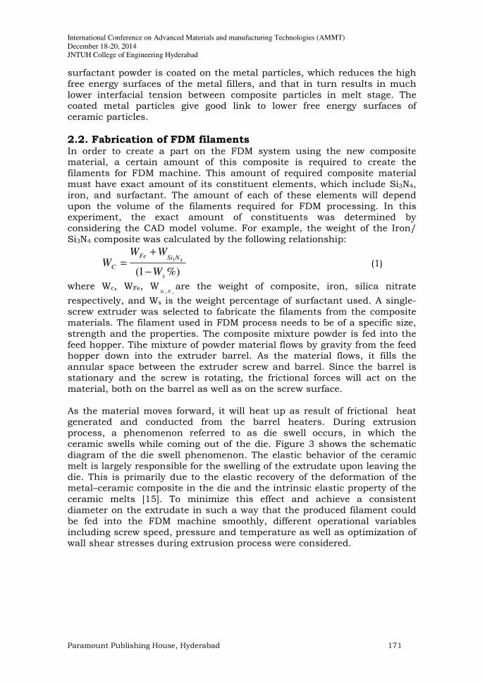
respectively, and Ws is the weight percentage of surfactant used. A single-screw extruder was selected to fabricate the filaments from the composite materials. The filament used in FDM process needs to be of a specific size, strength and the properties. The composite mixture powder is fed into the feed hopper. Tihe mixture of powder material flows by gravity from the feed hopper down into the extruder barrel. As the material flows, it fills the annular space between the extruder screw and barrel. Since the barrel is stationary and the screw is rotating, the frictional forces will act on the material, both on the barrel as well as on the screw surface. As the material moves forward, it will heat up as result of frictional heat generated and conducted from the barrel heaters. During extrusion process, a phenomenon referred to as die swell occurs, in which the ceramic swells while coming out of the die. Figure 3 shows the schematic diagram of the die swell phenomenon. The elastic behavior of the ceramic melt is largely responsible for the swelling of the extrudate upon leaving the die. This is primarily due to the elastic recovery of the deformation of the metal–ceramic composite in the die and the intrinsic elastic property of the ceramic melts [15]. To minimize this effect and achieve a consistent diameter on the extrudate in such a way that the produced filament could be fed into the FDM machine smoothly, different operational variables including screw speed, pressure and temperature as well as optimization of wall shear stresses during extrusion process were considered.
Thermo-mechanical properties of siliconnitrate ceramic composites……….
978-93-82163-46-6 All rights reserved 172
Figure 3: Schematic of ceramic melt swell.
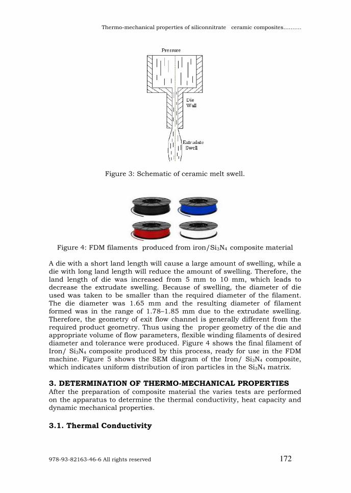
Figure 4: FDM filaments produced from iron/Si3N4 composite material
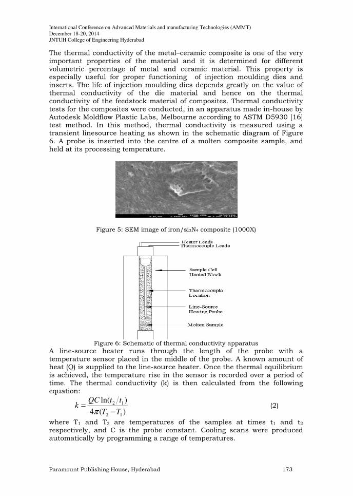
A die with a short land length will cause a large amount of swelling, while a die with long land length will reduce the amount of swelling. Therefore, the land length of die was increased from 5 mm to 10 mm, which leads to decrease the extrudate swelling. Because of swelling, the diameter of die used was taken to be smaller than the required diameter of the filament. The die diameter was 1.65 mm and the resulting diameter of filament formed was in the range of 1.78–1.85 mm due to the extrudate swelling. Therefore, the geometry of exit flow channel is generally different from the required product geometry. Thus using the proper geometry of the die and appropriate volume of flow parameters, flexible winding filaments of desired diameter and tolerance were produced. Figure 4 shows the final filament of Iron/ Si3N4 composite produced by this process, ready for use in the FDM machine. Figure 5 shows the SEM diagram of the Iron/ Si3N4 composite, which indicates uniform distribution of iron particles in the Si3N4 matrix.
3. DETERMINATION OF THERMO-MECHANICAL PROPERTIES After the preparation of composite material the varies tests are performed on the apparatus to determine the thermal conductivity, heat capacity and dynamic mechanical properties.
3.1. Thermal Conductivity
International Conference on Advanced Materials and manufacturing Technologies (AMMT)
December 18-20, 2014
JNTUH College of Engineering Hyderabad
Paramount Publishing House, Hyderabad 173
The thermal conductivity of the metal–ceramic composite is one of the very important properties of the material and it is determined for different volumetric percentage of metal and ceramic material. This property is especially useful for proper functioning of injection moulding dies and inserts. The life of injection moulding dies depends greatly on the value of thermal conductivity of the die material and hence on the thermal conductivity of the feedstock material of composites. Thermal conductivity tests for the composites were conducted, in an apparatus made in-house by Autodesk Moldflow Plastic Labs, Melbourne according to ASTM D5930 [16] test method. In this method, thermal conductivity is measured using a transient linesource heating as shown in the schematic diagram of Figure 6. A probe is inserted into the centre of a molten composite sample, and held at its processing temperature.
Figure 5: SEM image of iron/si3N4 composite (1000X)
Figure 6: Schematic of thermal conductivity apparatus
A line-source heater runs through the length of the probe with a temperature sensor placed in the middle of the probe. A known amount of heat (Q) is supplied to the line-source heater. Once the thermal equilibrium is achieved, the temperature rise in the sensor is recorded over a period of time. The thermal conductivity (k) is then calculated from the following equation:
)(4
)ln(
12
12
TT
ttQCk
−
=
π
(2)
where T1 and T2 are temperatures of the samples at times t1 and t2 respectively, and C is the probe constant. Cooling scans were produced automatically by programming a range of temperatures.
Thermo-mechanical properties of siliconnitrate ceramic composites……….
978-93-82163-46-6 All rights reserved 174
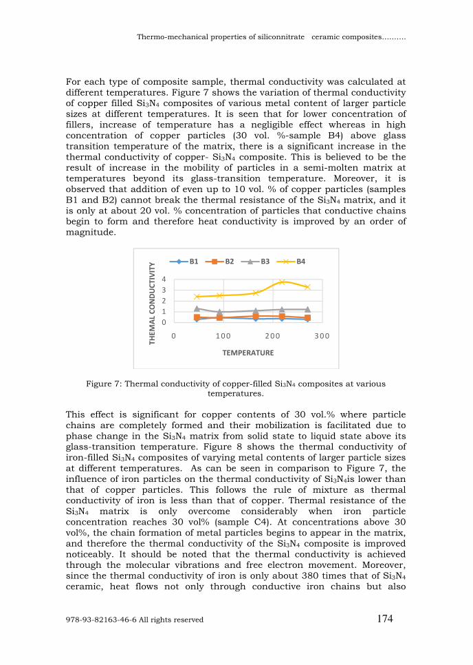
For each type of composite sample, thermal conductivity was calculated at different temperatures. Figure 7 shows the variation of thermal conductivity of copper filled Si3N4 composites of various metal content of larger particle sizes at different temperatures. It is seen that for lower concentration of fillers, increase of temperature has a negligible effect whereas in high concentration of copper particles (30 vol. %-sample B4) above glass transition temperature of the matrix, there is a significant increase in the thermal conductivity of copper- Si3N4 composite. This is believed to be the result of increase in the mobility of particles in a semi-molten matrix at temperatures beyond its glass-transition temperature. Moreover, it is observed that addition of even up to 10 vol. % of copper particles (samples B1 and B2) cannot break the thermal resistance of the Si3N4 matrix, and it is only at about 20 vol. % concentration of particles that conductive chains begin to form and therefore heat conductivity is improved by an order of magnitude.
Figure 7: Thermal conductivity of copper-filled Si3N4 composites at various temperatures.
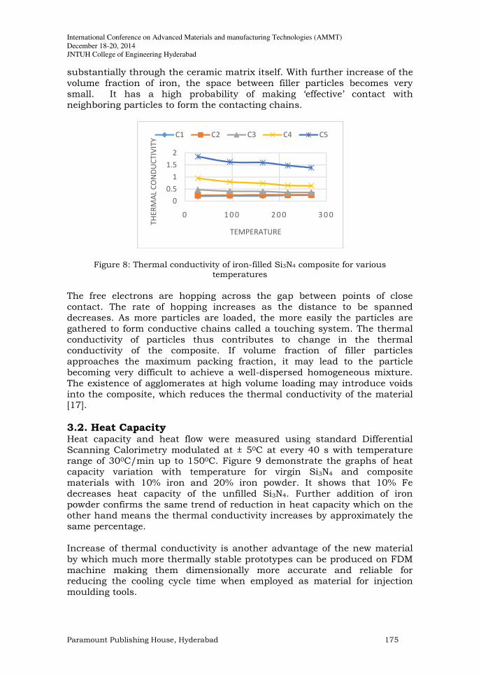
This effect is significant for copper contents of 30 vol.% where particle chains are completely formed and their mobilization is facilitated due to phase change in the Si3N4 matrix from solid state to liquid state above its glass-transition temperature. Figure 8 shows the thermal conductivity of iron-filled Si3N4 composites of varying metal contents of larger particle sizes at different temperatures. As can be seen in comparison to Figure 7, the influence of iron particles on the thermal conductivity of Si3N4is lower than that of copper particles. This follows the rule of mixture as thermal conductivity of iron is less than that of copper. Thermal resistance of the Si3N4 matrix is only overcome considerably when iron particle concentration reaches 30 vol% (sample C4). At concentrations above 30 vol%, the chain formation of metal particles begins to appear in the matrix, and therefore the thermal conductivity of the Si3N4 composite is improved noticeably. It should be noted that the thermal conductivity is achieved through the molecular vibrations and free electron movement. Moreover, since the thermal conductivity of iron is only about 380 times that of Si3N4 ceramic, heat flows not only through conductive iron chains but also
0
1
2
3
4
0 1 0 0 2 0 0 3 0 0
TH
EM
AL C
ON
DU
CT
IVIT
Y
TEMPERATURE
B1 B2 B3 B4
International Conference on Advanced Materials and manufacturing Technologies (AMMT)
December 18-20, 2014
JNTUH College of Engineering Hyderabad
Paramount Publishing House, Hyderabad 175
substantially through the ceramic matrix itself. With further increase of the volume fraction of iron, the space between filler particles becomes very small. It has a high probability of making ‘effective’ contact with neighboring particles to form the contacting chains.
Figure 8: Thermal conductivity of iron-filled Si3N4 composite for various temperatures
The free electrons are hopping across the gap between points of close contact. The rate of hopping increases as the distance to be spanned decreases. As more particles are loaded, the more easily the particles are gathered to form conductive chains called a touching system. The thermal conductivity of particles thus contributes to change in the thermal conductivity of the composite. If volume fraction of filler particles approaches the maximum packing fraction, it may lead to the particle becoming very difficult to achieve a well-dispersed homogeneous mixture. The existence of agglomerates at high volume loading may introduce voids into the composite, which reduces the thermal conductivity of the material [17].
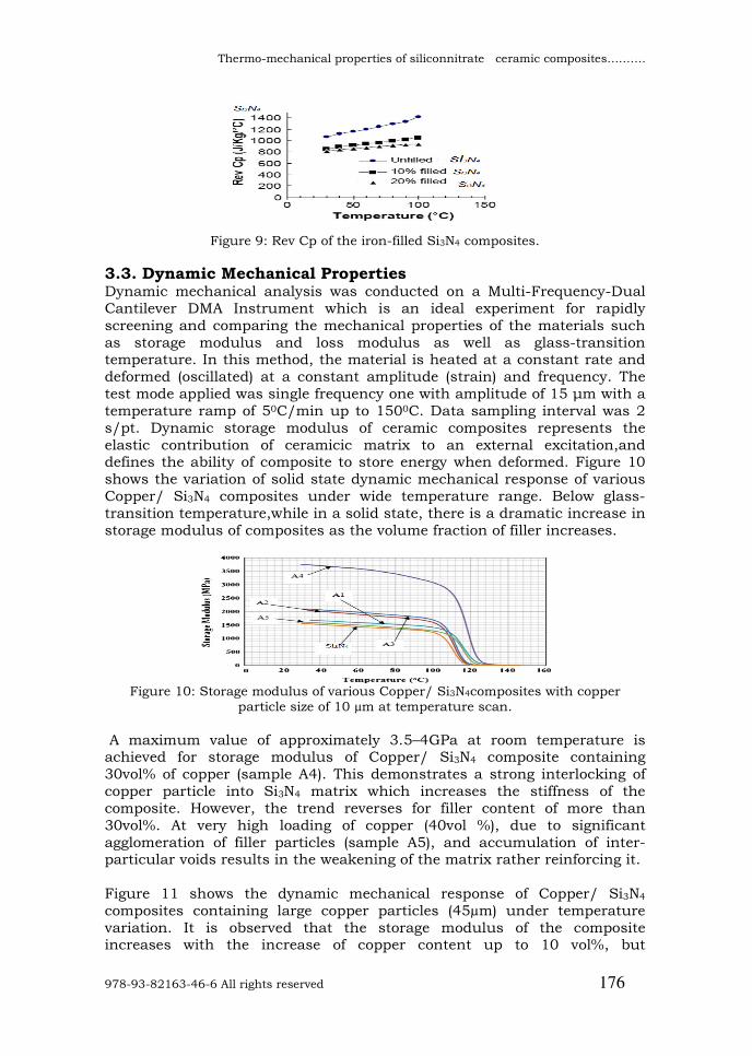
3.2. Heat Capacity Heat capacity and heat flow were measured using standard Differential Scanning Calorimetry modulated at ± 50C at every 40 s with temperature range of 300C/min up to 1500C. Figure 9 demonstrate the graphs of heat capacity variation with temperature for virgin Si3N4 and composite materials with 10% iron and 20% iron powder. It shows that 10% Fe decreases heat capacity of the unfilled Si3N4. Further addition of iron powder confirms the same trend of reduction in heat capacity which on the other hand means the thermal conductivity increases by approximately the same percentage. Increase of thermal conductivity is another advantage of the new material by which much more thermally stable prototypes can be produced on FDM machine making them dimensionally more accurate and reliable for reducing the cooling cycle time when employed as material for injection moulding tools.
0
0.5
1
1.5
2
0 1 0 0 2 0 0 3 0 0
TH
ER
MA
L C
ON
DU
CT
IVIT
Y
TEMPERATURE
C1 C2 C3 C4 C5
Thermo-mechanical properties of siliconnitrate ceramic composites……….
978-93-82163-46-6 All rights reserved 176
Figure 9: Rev Cp of the iron-filled Si3N4 composites.
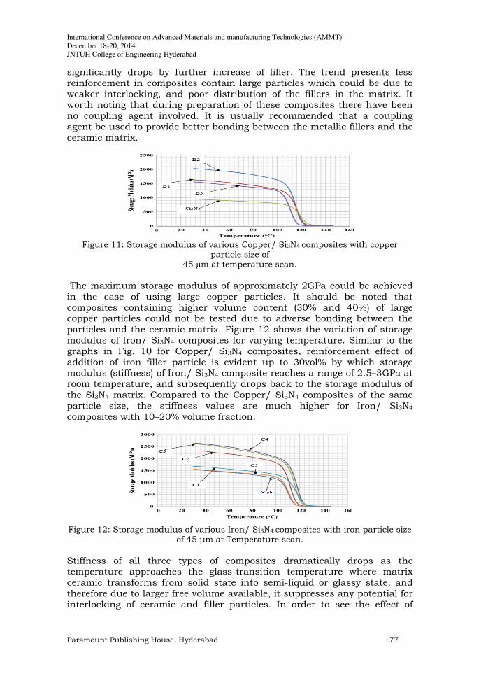
3.3. Dynamic Mechanical Properties Dynamic mechanical analysis was conducted on a Multi-Frequency-Dual Cantilever DMA Instrument which is an ideal experiment for rapidly screening and comparing the mechanical properties of the materials such as storage modulus and loss modulus as well as glass-transition temperature. In this method, the material is heated at a constant rate and deformed (oscillated) at a constant amplitude (strain) and frequency. The test mode applied was single frequency one with amplitude of 15 µm with a temperature ramp of 50C/min up to 1500C. Data sampling interval was 2 s/pt. Dynamic storage modulus of ceramic composites represents the elastic contribution of ceramicic matrix to an external excitation,and defines the ability of composite to store energy when deformed. Figure 10 shows the variation of solid state dynamic mechanical response of various Copper/ Si3N4 composites under wide temperature range. Below glass-transition temperature,while in a solid state, there is a dramatic increase in storage modulus of composites as the volume fraction of filler increases.
Figure 10: Storage modulus of various Copper/ Si3N4composites with copper
particle size of 10 µm at temperature scan.
A maximum value of approximately 3.5–4GPa at room temperature is achieved for storage modulus of Copper/ Si3N4 composite containing 30vol% of copper (sample A4). This demonstrates a strong interlocking of copper particle into Si3N4 matrix which increases the stiffness of the composite. However, the trend reverses for filler content of more than 30vol%. At very high loading of copper (40vol %), due to significant agglomeration of filler particles (sample A5), and accumulation of inter-particular voids results in the weakening of the matrix rather reinforcing it. Figure 11 shows the dynamic mechanical response of Copper/ Si3N4
composites containing large copper particles (45µm) under temperature variation. It is observed that the storage modulus of the composite increases with the increase of copper content up to 10 vol%, but
International Conference on Advanced Materials and manufacturing Technologies (AMMT)
December 18-20, 2014
JNTUH College of Engineering Hyderabad
Paramount Publishing House, Hyderabad 177
significantly drops by further increase of filler. The trend presents less reinforcement in composites contain large particles which could be due to weaker interlocking, and poor distribution of the fillers in the matrix. It worth noting that during preparation of these composites there have been no coupling agent involved. It is usually recommended that a coupling agent be used to provide better bonding between the metallic fillers and the ceramic matrix.
Figure 11: Storage modulus of various Copper/ Si3N4 composites with copper
particle size of 45 µm at temperature scan.
The maximum storage modulus of approximately 2GPa could be achieved in the case of using large copper particles. It should be noted that composites containing higher volume content (30% and 40%) of large copper particles could not be tested due to adverse bonding between the particles and the ceramic matrix. Figure 12 shows the variation of storage modulus of Iron/ Si3N4 composites for varying temperature. Similar to the graphs in Fig. 10 for Copper/ Si3N4 composites, reinforcement effect of addition of iron filler particle is evident up to 30vol% by which storage modulus (stiffness) of Iron/ Si3N4 composite reaches a range of 2.5–3GPa at room temperature, and subsequently drops back to the storage modulus of the Si3N4 matrix. Compared to the Copper/ Si3N4 composites of the same particle size, the stiffness values are much higher for Iron/ Si3N4 composites with 10–20% volume fraction.
Figure 12: Storage modulus of various Iron/ Si3N4 composites with iron particle size
of 45 µm at Temperature scan.
Stiffness of all three types of composites dramatically drops as the temperature approaches the glass-transition temperature where matrix ceramic transforms from solid state into semi-liquid or glassy state, and therefore due to larger free volume available, it suppresses any potential for interlocking of ceramic and filler particles. In order to see the effect of
Thermo-mechanical properties of siliconnitrate ceramic composites……….
978-93-82163-46-6 All rights reserved 178
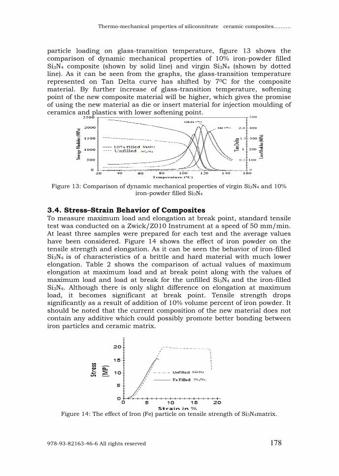
particle loading on glass-transition temperature, figure 13 shows the comparison of dynamic mechanical properties of 10% iron-powder filled Si3N4 composite (shown by solid line) and virgin Si3N4 (shown by dotted line). As it can be seen from the graphs, the glass-transition temperature represented on Tan Delta curve has shifted by 70C for the composite material. By further increase of glass-transition temperature, softening point of the new composite material will be higher, which gives the promise of using the new material as die or insert material for injection moulding of ceramics and plastics with lower softening point.
Figure 13: Comparison of dynamic mechanical properties of virgin Si3N4 and 10%
iron-powder filled Si3N4
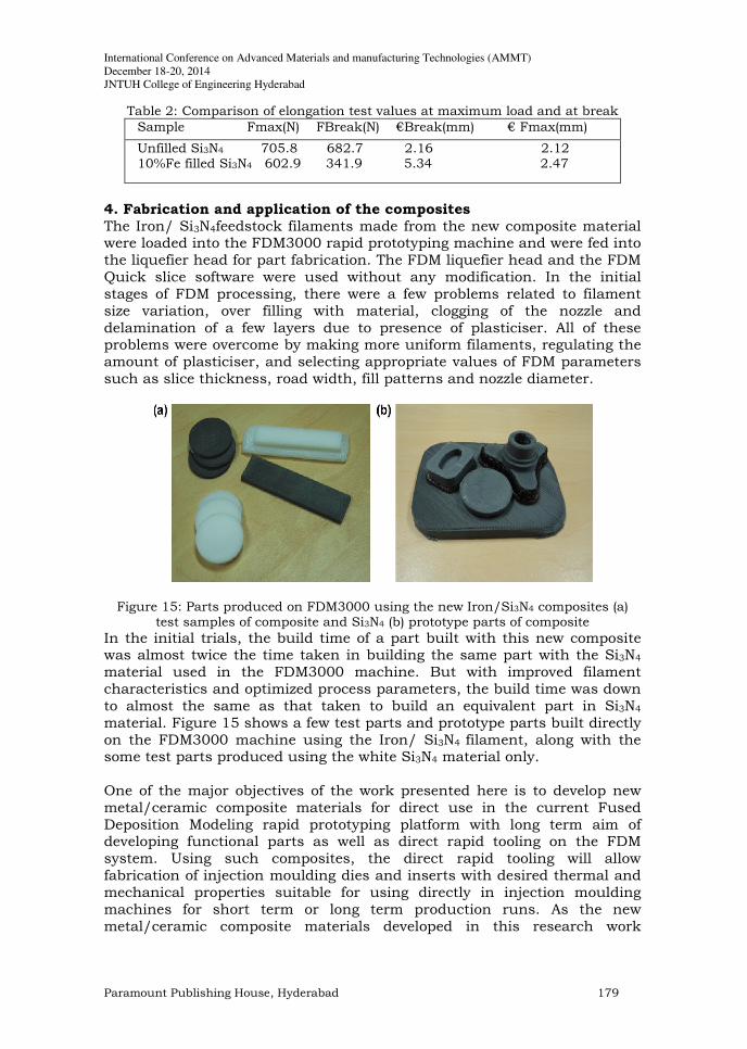
3.4. Stress–Strain Behavior of Composites To measure maximum load and elongation at break point, standard tensile test was conducted on a Zwick/Z010 Instrument at a speed of 50 mm/min. At least three samples were prepared for each test and the average values have been considered. Figure 14 shows the effect of iron powder on the tensile strength and elongation. As it can be seen the behavior of iron-filled Si3N4 is of characteristics of a brittle and hard material with much lower elongation. Table 2 shows the comparison of actual values of maximum elongation at maximum load and at break point along with the values of maximum load and load at break for the unfilled Si3N4 and the iron-filled Si3N4. Although there is only slight difference on elongation at maximum load, it becomes significant at break point. Tensile strength drops significantly as a result of addition of 10% volume percent of iron powder. It should be noted that the current composition of the new material does not contain any additive which could possibly promote better bonding between iron particles and ceramic matrix.
Figure 14: The effect of Iron (Fe) particle on tensile strength of Si3N4matrix.
International Conference on Advanced Materials and manufacturing Technologies (AMMT)
December 18-20, 2014
JNTUH College of Engineering Hyderabad
Paramount Publishing House, Hyderabad 179
Table 2: Comparison of elongation test values at maximum load and at break
Sample Fmax(N) FBreak(N) €Break(mm) € Fmax(mm)
Unfilled Si3N4 705.8 682.7 2.16 2.12 10%Fe filled Si3N4 602.9 341.9 5.34 2.47
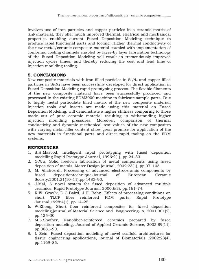
4. Fabrication and application of the composites The Iron/ Si3N4feedstock filaments made from the new composite material were loaded into the FDM3000 rapid prototyping machine and were fed into the liquefier head for part fabrication. The FDM liquefier head and the FDM Quick slice software were used without any modification. In the initial stages of FDM processing, there were a few problems related to filament size variation, over filling with material, clogging of the nozzle and delamination of a few layers due to presence of plasticiser. All of these problems were overcome by making more uniform filaments, regulating the amount of plasticiser, and selecting appropriate values of FDM parameters such as slice thickness, road width, fill patterns and nozzle diameter.
Figure 15: Parts produced on FDM3000 using the new Iron/Si3N4 composites (a) test samples of composite and Si3N4 (b) prototype parts of composite
In the initial trials, the build time of a part built with this new composite was almost twice the time taken in building the same part with the Si3N4 material used in the FDM3000 machine. But with improved filament characteristics and optimized process parameters, the build time was down to almost the same as that taken to build an equivalent part in Si3N4 material. Figure 15 shows a few test parts and prototype parts built directly on the FDM3000 machine using the Iron/ Si3N4 filament, along with the some test parts produced using the white Si3N4 material only. One of the major objectives of the work presented here is to develop new metal/ceramic composite materials for direct use in the current Fused Deposition Modeling rapid prototyping platform with long term aim of developing functional parts as well as direct rapid tooling on the FDM system. Using such composites, the direct rapid tooling will allow fabrication of injection moulding dies and inserts with desired thermal and mechanical properties suitable for using directly in injection moulding machines for short term or long term production runs. As the new metal/ceramic composite materials developed in this research work
Thermo-mechanical properties of siliconnitrate ceramic composites……….
978-93-82163-46-6 All rights reserved 180
involves use of iron particles and copper particles in a ceramic matrix of Si3N4material, they offer much improved thermal, electrical and mechanical properties enabling current Fused Deposition Modeling technique to produce rapid functional parts and tooling. Higher thermal conductivity of the new metal/ceramic composite material coupled with implementation of conformal cooling channels enabled by layer-by layer fabrication technology of the Fused Deposition Modeling will result in tremendously improved injection cycles times, and thereby reducing the cost and lead time of injection moulding tooling.
5. CONCLUSIONS New composite materials with iron filled particles in Si3N4 and copper filled particles in Si3N4 have been successfully developed for direct application in Fused Deposition Modeling rapid prototyping process. The flexible filaments of the new composite material have been successfully produced and processed in the existing FDM3000 machine to fabricate sample parts. Due to highly metal particulate filled matrix of the new composite material, injection tools and inserts are made using this material on Fused Deposition Modeling, will demonstrate a higher stiffness comparing to those made out of pure ceramic material resulting in withstanding higher injection moulding pressures. Moreover, comparison of thermal conductivity and dynamic mechanical test values of the new composites with varying metal filler content show great promise for application of the new materials in functional parts and direct rapid tooling on the FDM systems.
REFERENCES 1. S.H.Masood, Intelligent rapid prototyping with fused deposition
modelling.Rapid Prototype Journal, 1996:2(1), pp.24–33. 2. G.Wu, Solid freeform fabrication of metal components using fused
deposition of metals. Mater Design journal, 2002:23(1), pp.97–105. 3. M. Allahverdi, Processing of advanced electroceramic components by
fused depositiontechnique,Journal of European Ceramic Society,2001:21(10–11),pp.1485–90.
4. J.Mal, A novel system for fused deposition of advanced multiple ceramics. Rapid Prototype Journal, 2000:6(3), pp.161–74.
5. R.W. GrayIv, D.G.Baird, J.H. Bøhn, Effects of processing conditions on short TLCP fiber reinforced FDM parts, Rapid Prototype Journal,1998:4(1), pp.14–25.
6. W.Zhong, Short fiber reinforced composites for fused deposition modeling,journal of Material Science and Engineering- A, 2001:301(2), pp.125–30.
7. M.L.Shofner, Nanofiber-reinforced ceramics prepared by fused deposition modeling, Journal of Applied Ceramic Science, 2003:89(11), pp.3081–90.
8. I. Zein, Fused deposition modeling of novel scaffold architectures for tissue engineering applications, journal of Biomaterials ,2002:23(4), pp.1169–85.
International Conference on Advanced Materials and manufacturing Technologies (AMMT)
December 18-20, 2014
JNTUH College of Engineering Hyderabad
Paramount Publishing House, Hyderabad 181
9. M.Endres, D.W.Hutmacher, Osteogenic induction of human bone marrow-derived mesenchymal progenitor cells in novel synthetic ceramic-hydrogel matrices,Journal of Tissue Eng 2003:9(4), pp.689–702.
10. B. Rai, The effect of rhBMP-2 on canine osteoblasts seeded onto 3D bioactive polycaprolactone scaffolds, International Journal of Biomaterials 2004:25(24), pp.5499–506.
11. T.B.F. Woodfield, Design of porous scaffolds for cartilage tissue engineering using a three-dimensional fiber-deposition technique, International Journal of Biomaterials, 2004:25(18), pp.4149–61.
12. S.J.Kalita, Development of controlled porosity ceramic–ceramic composite scaffolds via fused deposition modeling, Journal of Material Science and Engineering-C, 2003:23(5), pp.611–20.
13. S.C.Tsai, D.Botts, and J.Plouff, Effects of particle properties on the rheology of concentrated noncolloidal suspensions, Journal of Rheology, 1992:36(7), pp.1291–305.
14. S.H.Masood, W.Q.Song, Thermal characteristics of a new metal/ceramic material for FDM rapid prototyping process. Assembly Automation, 2005: 25(4), pp. 309–15.
15. C. Rauwendaal, Ceramic extrusion. Munich: Hanser Publishers 2001: pp.460-61
16. American society for testing of material-D5930. Standard test method for thermal conductivity of plastics by means of a transient line-source technique. ASTM International: West Conshohocken, PA: 2009.
17. D.M.Bigg, Mechanical, thermal, and electrical properties of metal fiber-filled ceramic composites, Journal of Ceramic Engineering science1979:19(16), pp.1188–92.