thermal strategy sam heys rutherford appleton laboratory
DESCRIPTION
Thermal Strategy Sam Heys Rutherford Appleton Laboratory. Mission Overview. Orbit: Nominal Phase Solar Distance: 0.21 - 0.8AU. Cruise Phase Maximum Aphelion Distance:1.21A. 149 day orbital period. Mission Phases: Cruise Phase: 0 -1.86 years Nominal Mission:1.86 -4.74 years - PowerPoint PPT PresentationTRANSCRIPT
Thermal Strategy Sam Heys, RAL
EUV Spectrometer Proto-Consortium Meeting November 28th 2001 Coseners House
1
Thermal Strategy
Sam HeysRutherford Appleton Laboratory
Thermal Strategy Sam Heys, RAL
EUV Spectrometer Proto-Consortium Meeting November 28th 2001 Coseners House
2
Mission Overview
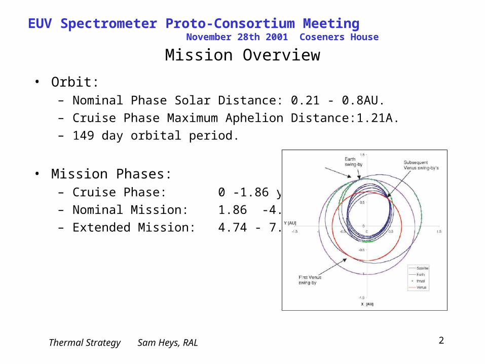
• Orbit:– Nominal Phase Solar Distance: 0.21 - 0.8AU.
– Cruise Phase Maximum Aphelion Distance:1.21A.
– 149 day orbital period.
• Mission Phases:– Cruise Phase: 0 -1.86 years
– Nominal Mission: 1.86 -4.74 years
– Extended Mission: 4.74 - 7.01 years
Thermal Strategy Sam Heys, RAL
EUV Spectrometer Proto-Consortium Meeting November 28th 2001 Coseners House
3
Mission Overview
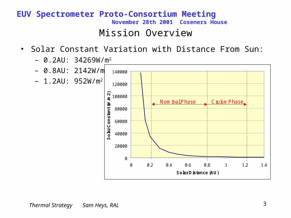
• Solar Constant Variation with Distance From Sun:– 0.2AU: 34269W/m2
– 0.8AU: 2142W/m2
– 1.2AU: 952W/m2
Solar Orbiter -Mission Range
0
20000
40000
60000
80000
100000
120000
140000
0 0.2 0.4 0.6 0.8 1 1.2 1.4
Solar Distance (AU)
So
lar
Co
ns
tan
t (W
/m2
)
Nominal Phase Cruise Phase
Thermal Strategy Sam Heys, RAL
EUV Spectrometer Proto-Consortium Meeting November 28th 2001 Coseners House
4
Spacecraft Design
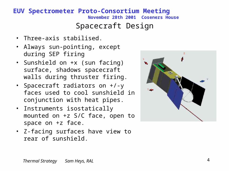
• Three-axis stabilised.• Always sun-pointing, except during
SEP firing• Sunshield on +x (sun facing) surface,
shadows spacecraft walls during thruster firing.
• Spacecraft radiators on +/-y faces used to cool sunshield in conjunction with heat pipes.
• Instruments isostatically mounted on +z S/C face, open to space on +z face.
• Z-facing surfaces have view to rear of sunshield.
Thermal Strategy Sam Heys, RAL
EUV Spectrometer Proto-Consortium Meeting November 28th 2001 Coseners House
5
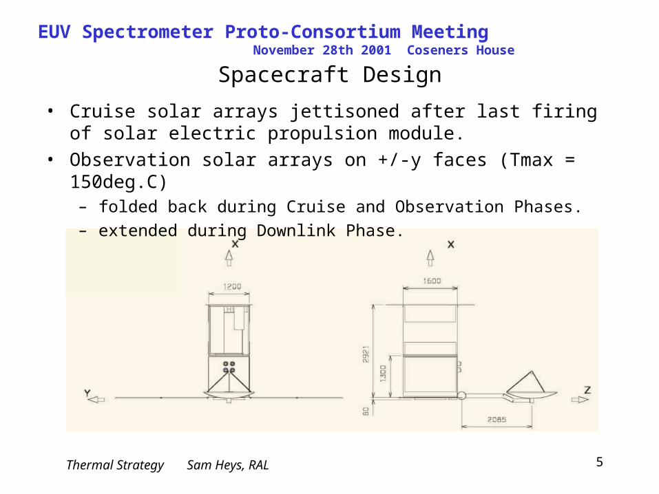
Spacecraft Design
• Cruise solar arrays jettisoned after last firing of solar electric propulsion module.
• Observation solar arrays on +/-y faces (Tmax = 150deg.C)– folded back during Cruise and Observation Phases.
– extended during Downlink Phase.
Thermal Strategy Sam Heys, RAL
EUV Spectrometer Proto-Consortium Meeting November 28th 2001 Coseners House
6
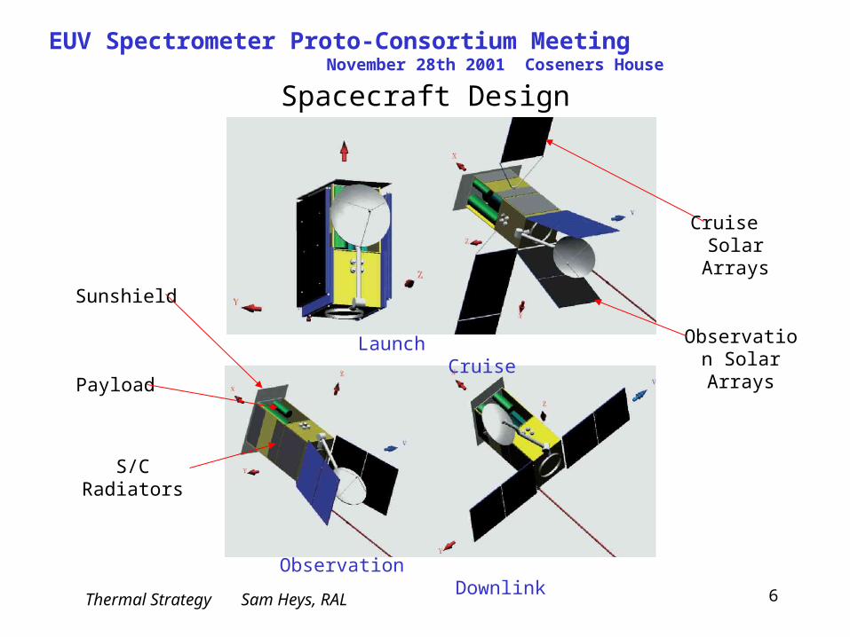
Spacecraft Design
Launch Cruise
Observation Downlink
Payload
Sunshield
Observation Solar Arrays
S/C Radiators
Cruise Solar Arrays
Thermal Strategy Sam Heys, RAL
EUV Spectrometer Proto-Consortium Meeting November 28th 2001 Coseners House
7
Instrument Thermal Requirements
• Thermal control system must accommodate changes in solar constant from 952W/m2 (1.2AU) to 34,269W/m2 (0.2AU).
• Structure and Optics Temperature:– Multilayer coatings on optics are assumed to be the limiting factor in
defining the instrument bulk temperature.
– A temperature limit for such coatings of <100deg.C is assumed.
• Detector Temperature: target<-80deg.C, requirement <-60deg.C.• Minimise temperature gradients through instrument.• Minimise temperature fluctuations around orbit / throughout mission.• Size and mass limitations (e.g. instrument radiators).• Heater power limitations (cruise/aphelion)• Control heat loads to/from spacecraft to ‘acceptable’ level.
Thermal Strategy Sam Heys, RAL
EUV Spectrometer Proto-Consortium Meeting November 28th 2001 Coseners House
8
Thermal Design -General
• Aperture size: minimise as far as possible.• Reflect incoming solar load to Space where possible.• Multilayer Coatings -control absorbed thermal load on optics.• Optics absorbed loads dumped to Space via radiators on +z face.• Dedicated cold radiator for detector cooling.• High conductance cold fingers or looped heat pipes (LHP) to radiators.• Heat switches / LHPs used to disconnect radiators during cold periods, as
necessary. • Use of compensating heaters during Nominal Phase (around aphelion),
and Cruise Phase.• High conductivity materials for main structure, or radiative isolation of
structure, to reduce temperature gradients.• Low CTE materials for structure (CFRP, SiC)
Thermal Strategy Sam Heys, RAL
EUV Spectrometer Proto-Consortium Meeting November 28th 2001 Coseners House
9
Hardware: Radiator Conductive Links
• High conductance links required in order to transfer absorbed heat from optics components to instrument radiators with minimum temperature differential.
• Necessary to disconnect radiators during cold phases to limit survival heater power and temperature fluctuations.
• Options:– Conventional Cold Finger and Heat switch: relatively low conductance.
Heat switch results in additional thermal impedance in link -not suitable for very high loads due to high resulting temperature differential.
– Looped Heat Pipe (LHP): Two-phase, passive heat transfer device - small temperature differentials and high heat transport power densities.
Thermal Strategy Sam Heys, RAL
EUV Spectrometer Proto-Consortium Meeting November 28th 2001 Coseners House
10
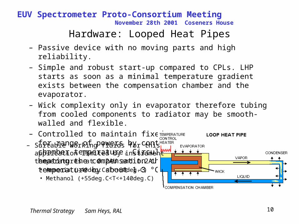
Hardware: Looped Heat Pipes– Passive device with no moving parts and high reliability.
– Simple and robust start-up compared to CPLs. LHP starts as soon as a minimal temperature gradient exists between the compensation chamber and the evaporator.
– Wick complexity only in evaporator therefore tubing from cooled components to radiator may be smooth-walled and flexible.
– Controlled to maintain fixed evaporator temperatures for range of powers by controlling the compensation chamber temperature. Circulation can be stopped by heating the compensation chamber above the evaporator temperature by about 1-3 °C.
– Suitable working fluids for this application limited by instrument temperatures at 0.2AU and 1.2AU
• Ammonia (-40deg.C<T<+80deg.C)• Methanol (+55deg.C<T<+140deg.C)
Thermal Strategy Sam Heys, RAL
EUV Spectrometer Proto-Consortium Meeting November 28th 2001 Coseners House
11
Hardware: Looped Heat Pipes
Thermal Strategy Sam Heys, RAL
EUV Spectrometer Proto-Consortium Meeting November 28th 2001 Coseners House
12
Hardware: Multilayer Technology• Incoming thermal loads on the various optics surfaces can be controlled
through the use of coatings with specific thermo-optical properties, which also meet optical requirements.
• Optical surfaces must reflect in the imaging wavelength ranges: – 17nm-22nm, 58nm to 63nm and >91.2nm.
• In order to control the thermal load from the sun, the surfaces must either reflect or absorb in the range 0.3m to 2.5m.– Reflective Multilayer:
• Si-C/Gold/10 layers Silicon-Platinum/Silicon/Carbon• reflectivity (vis/IR) = 0.9• reflectivity (imaging) = 0.24
– Absorbing Multilayer: • Si-C/Gold/10 layers Silicon-Platinum/Platinum• reflectivity (vis/IR) = 0.3• reflectivity (imaging) = 0.24
Thermal Strategy Sam Heys, RAL
EUV Spectrometer Proto-Consortium Meeting November 28th 2001 Coseners House
13
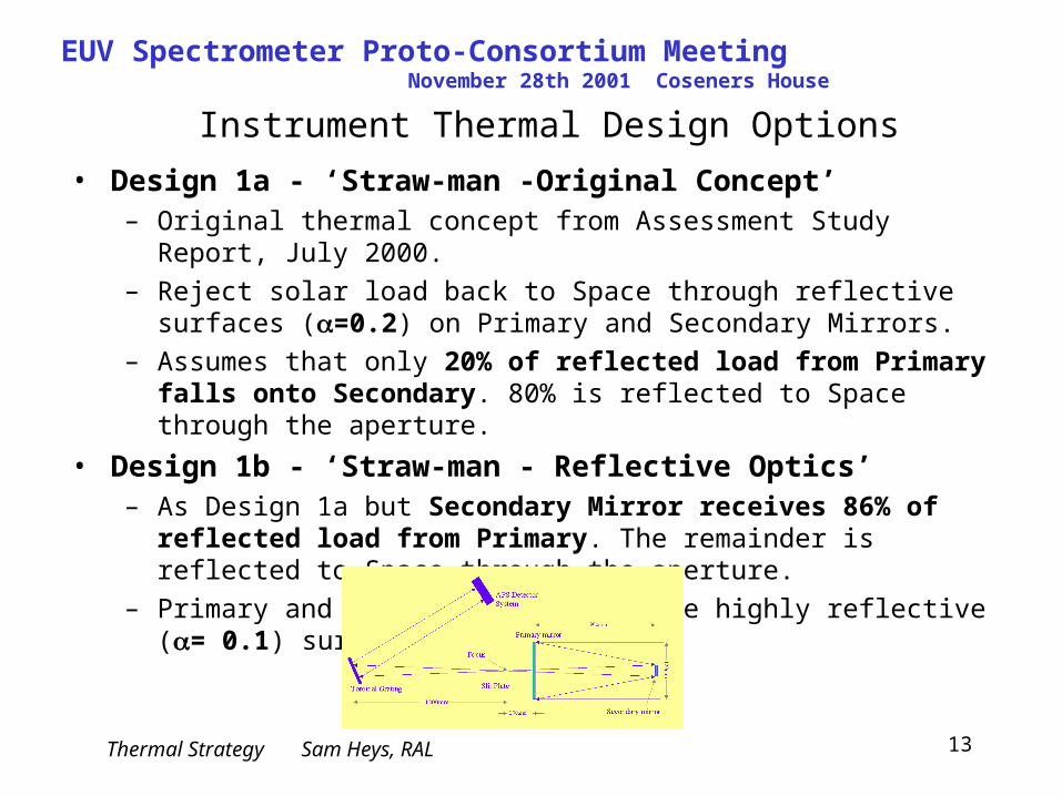
Instrument Thermal Design Options
• Design 1a - ‘Straw-man -Original Concept’– Original thermal concept from Assessment Study Report, July 2000.
– Reject solar load back to Space through reflective surfaces (=0.2) on Primary and Secondary Mirrors.
– Assumes that only 20% of reflected load from Primary falls onto Secondary. 80% is reflected to Space through the aperture.
• Design 1b - ‘Straw-man - Reflective Optics’– As Design 1a but Secondary Mirror receives 86% of reflected load
from Primary. The remainder is reflected to Space through the aperture.
– Primary and Secondary Mirrors have highly reflective (= 0.1) surfaces.
Thermal Strategy Sam Heys, RAL
EUV Spectrometer Proto-Consortium Meeting November 28th 2001 Coseners House
14
Instrument Thermal Design Options
• Design 1c -‘Straw-man -Absorbing Optics’– Since cooling of the Secondary Mirror or Slit Plate appears challenging,
Primary Mirror surface made absorbing (=0.7).
– Heat absorbed by Primary transferred to radiator via looped heat pipe.
– Secondary Mirror receives 86% of reflected load from Primary. The remainder is reflected to Space through the aperture.
– Secondary Mirror reflecting (= 0.1).
– Heat absorbed by Secondary transferred to radiator via cold finger.
– Slit Plate loads conducted to radiator via cold finger.
• Design 1d -‘Straw-man -Absorbing Optics’– As Design 1c except Secondary Mirror absorbing (= 0.7) in the thermal
infra-red.
Thermal Strategy Sam Heys, RAL
EUV Spectrometer Proto-Consortium Meeting November 28th 2001 Coseners House
15
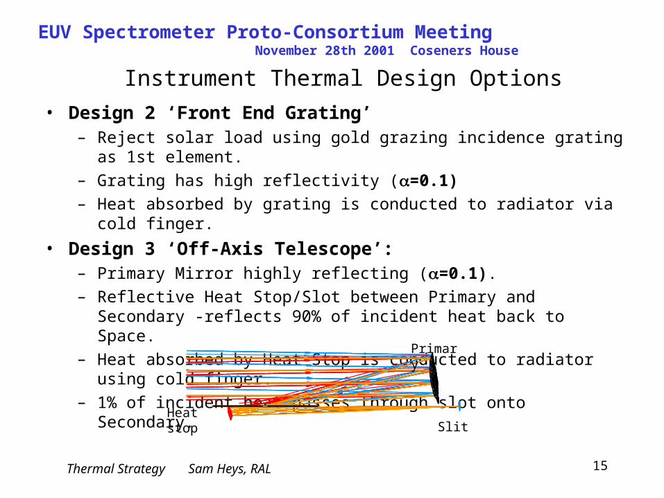
Instrument Thermal Design Options
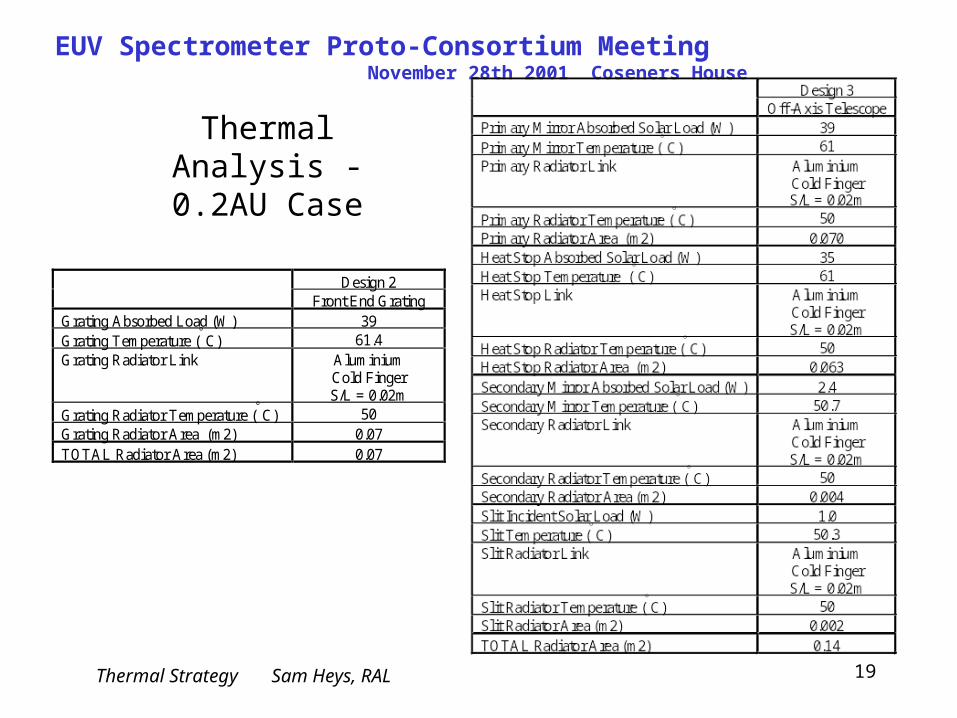
• Design 2 ‘Front End Grating’– Reject solar load using gold grazing incidence grating as 1st element.
– Grating has high reflectivity (=0.1)
– Heat absorbed by grating is conducted to radiator via cold finger.
• Design 3 ‘Off-Axis Telescope’:– Primary Mirror highly reflecting (=0.1).
– Reflective Heat Stop/Slot between Primary and Secondary -reflects 90% of incident heat back to Space.
– Heat absorbed by Heat Stop is conducted to radiator using cold finger.
– 1% of incident heat passes through slot onto Secondary.
Heat stop
Primary
Slit

Thermal Strategy Sam Heys, RAL
EUV Spectrometer Proto-Consortium Meeting November 28th 2001 Coseners House
16
Thermal Analysis
• Limited thermal analysis of the designs has been performed using Excel spreadsheets. Aim is to assess the thermal implications of the various optics designs.
• Solar loads calculated within spreadsheet, with inputs on beam path from optics team.
• Optics Assumptions– Aperture Diameter 0.12m– Primary Mirror Diameter 0.12m– Secondary Mirror Diameter 0.02m
• Results show approximate radiator areas required for cooling of optics components at the 0.2AU perihelion case.
Thermal Strategy Sam Heys, RAL
EUV Spectrometer Proto-Consortium Meeting November 28th 2001 Coseners House
17
Thermal Analysis
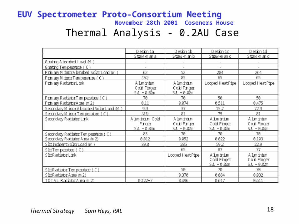
• Generally aim to maintain optics at approximately 80deg.C (20deg.C margin on multilayer Tmax).
• However where LHPs are used the temperature is reduced in order that working fluid maximum temperature is not exceeded (ammonia Tmax = +80deg.C).
• Calculations of radiator areas assume emissivity of 0.9 and perfect view to Space.
• In fact radiators on the +z surface have a significant view (~20%) to the rear face of the Spacecraft Sunshield.
• Therefore actual radiator sizes will be larger than those calculated.
Thermal Strategy Sam Heys, RAL
EUV Spectrometer Proto-Consortium Meeting November 28th 2001 Coseners House
18
Thermal Analysis - 0.2AU Case
Thermal Strategy Sam Heys, RAL
EUV Spectrometer Proto-Consortium Meeting November 28th 2001 Coseners House
19
Design 2Front End Grating
Grating Absorbed Load (W) 39Grating Temperature (° C) 61.4Grating Radiator Link Aluminium
Cold FingerS/L = 0.02m
Grating Radiator Temperature (° C) 50Grating Radiator Area (m2) 0.07TOTAL Radiator Area (m2) 0.07
Thermal Analysis - 0.2AU Case
Thermal Strategy Sam Heys, RAL
EUV Spectrometer Proto-Consortium Meeting November 28th 2001 Coseners House
20
Analysis Summary
– Design 1: Straw-man Optical Design (1a-d) requires large radiator area (>0.6m2) and LHPs to maintain optics at approximately 80deg.C at 0.2AU.
• Design 1a – Since shown that sizing of Secondary Mirror to receive 20% of reflected signal is
unacceptable to the optics design.
• Design 1b – Slit Plate loads unacceptable? - beam highly focussed at this point. LHP required
on Primary.
• Design 1c – High Slit Plate load - beam highly focussed at this point. LHP required on
Primary.
• Design 1d – High Secondary and Slit Plate loads. Issue of removing heat from Secondary.
LHP required on Primary.
Thermal Strategy Sam Heys, RAL
EUV Spectrometer Proto-Consortium Meeting November 28th 2001 Coseners House
21
Analysis Summary
– Design 2: • Significantly reduced instrument absorbed loads and hence radiator sizes and
temperatures.
– Design 3:• Significantly reduced instrument absorbed loads and hence radiator sizes and
temperatures.• Easier to remove heat from Heat Stop and Secondary since not in Primary beam.• Focussed load on Heat Stop may be cause for concern.
Thermal Strategy Sam Heys, RAL
EUV Spectrometer Proto-Consortium Meeting November 28th 2001 Coseners House
22
Summary
• Radiators used to dump absorbed optics heat to Space.• Straw-man design requires radiator area of >0.6m2 for 80deg.C
optics.• Alternative designs have significantly smaller radiators and lower
temperatures.• Separate cold (<-80deg.C) detector radiator.• High couplings from optics to radiators -may require LHP system.• Radiators may require decoupling during cold phases.• Compensation heaters required during cold phases.• Multilayers must control thermal/IR load in addition to imaging
wavelengths.
Thermal Strategy Sam Heys, RAL
EUV Spectrometer Proto-Consortium Meeting November 28th 2001 Coseners House
23
Future Work
• More detailed analysis of various design options, with iterations of current optical designs / alternative designs.
• Transient analysis of orbital fluctuations. • Assessment of survival heater power requirements during Cruise
and Nominal Phases. • Confirmation of maximum temperature of multilayers.• Further investigation of looped heat pipes -feasibility/ design/
working fluid/ temperature limitations/ performance/supplier/ mass/ volume, etc.
• Further investigations into heat switches -feasibility/ design/ temperature limitations/ performance/supplier/ mass/ volume, etc.
• Assessment of heat loads onto detector module and resulting detector radiator design.
• Spacecraft interface...