thermal profile dependence on embrittlement of … · thermal profile dependence on embrittlement...
TRANSCRIPT
1
Martin Karl AnselmProcess Research Engineer
Failure Analyst
Universal Instruments SMT Laboratory
Thermal Profile Dependence onEmbrittlement of Ni/SnPb/Cu Joints
2
Overview
• There have been two major failure analysis projects involving brittle ENIG BGA constructions.– In both cases (Cu,Ni)6Sn5 was produced to a high degree at the ENIG
pad surface.– DOE showed that brittle failure mode was eliminated by soldering ENIG
component to ENIG PCB.– Ball shear testing of “dead bug” BGAs at time zero and following
thermal aging did not produce failures.– In both cases the brittle failure rate was dependant on time above 183C
during convection assembly.
3
Failure Mode Classification
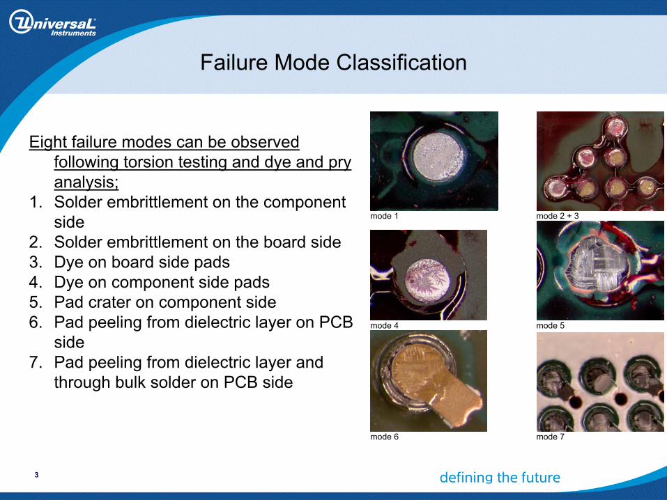
Eight failure modes can be observed following torsion testing and dye and pry analysis;
1. Solder embrittlement on the component side
2. Solder embrittlement on the board side3. Dye on board side pads4. Dye on component side pads5. Pad crater on component side6. Pad peeling from dielectric layer on PCB
side7. Pad peeling from dielectric layer and
through bulk solder on PCB side
mode 1 mode 2 + 3
mode 4 mode 5
mode 6 mode 7
4
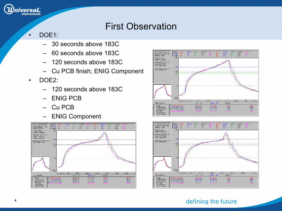
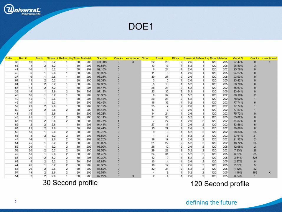
First Observation• DOE1:
– 30 seconds above 183C– 60 seconds above 183C– 120 seconds above 183C– Cu PCB finish; ENIG Component
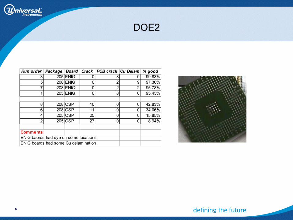
• DOE2:– 120 seconds above 183C– ENIG PCB– Cu PCB– ENIG Component
5
DOE1
Order Run # Block Stress # Reflow Liq Time Material Good % Cracks x-sectioned38 10 1 5.2 1 30 205 100.00% 0 X53 1 2 5.2 1 30 202 99.83% 041 16 1 5.2 1 30 202 99.16% 045 6 1 2.6 1 30 202 98.99% 037 6 1 2.6 1 30 202 98.31% 064 11 2 5.2 1 30 205 98.31% 061 1 2 5.2 1 30 202 97.98% 056 11 2 5.2 1 30 205 97.47% 039 14 1 2.6 2 30 202 97.13% 049 16 1 5.2 1 30 202 96.96% 040 15 1 2.6 1 30 205 96.46% 046 10 1 5.2 1 30 205 96.46% 059 23 2 2.6 1 30 202 96.12% 060 29 2 2.6 2 30 202 95.45% 048 15 1 2.6 1 30 205 95.28% 043 25 1 5.2 2 30 205 95.11% 065 19 2 2.6 2 30 205 94.77% 162 2 2 2.6 1 30 205 94.44% 067 23 2 2.6 1 30 202 94.44% 050 18 1 2.6 2 30 205 93.76% 055 8 2 5.2 2 30 202 93.59% 047 14 1 2.6 2 30 202 93.25% 051 25 1 5.2 2 30 205 93.09% 052 26 1 5.2 2 30 202 93.09% 058 20 2 5.2 2 30 205 92.58% 042 18 1 2.6 2 30 205 91.40% 066 20 2 5.2 2 30 205 90.39% 063 8 2 5.2 2 30 202 89.88% 044 26 1 5.2 2 30 202 89.38% 068 29 2 2.6 2 30 202 87.52% 057 19 2 2.6 2 30 205 86.51% 054 2 2 2.6 1 30 205 82.29% 0 X
Order Run # Block Stress # Reflow Liq Time Material Good % Cracks x-sectioned22 28 2 2.6 1 120 205 97.47% 0 X13 13 1 5.2 1 120 205 96.80% 36 24 1 2.6 1 120 202 95.78% 0
11 5 1 2.6 1 120 205 94.27% 030 28 2 2.6 1 120 205 93.93% 03 5 1 2.6 1 120 205 93.42% 05 13 1 5.2 1 120 205 88.70% 0
28 21 2 5.2 1 120 202 85.67% 023 30 2 5.2 1 120 205 83.64% 08 32 1 5.2 1 120 202 80.10% 2
20 21 2 5.2 1 120 202 78.92% 116 32 1 5.2 1 120 202 77.74% 625 7 2 2.6 1 120 202 77.74% 117 7 2 2.6 1 120 202 77.57% 114 24 1 2.6 1 120 202 75.72% 031 30 2 5.2 1 120 205 55.82% 07 27 1 2.6 2 120 202 34.57% 0
27 17 2 2.6 2 120 202 33.56% 615 27 1 2.6 2 120 202 30.86% 89 3 1 5.2 2 120 202 28.33% 251 3 1 5.2 2 120 202 23.61% 21
19 17 2 2.6 2 120 202 21.92% 221 22 2 5.2 2 120 202 18.72% 2626 12 2 2.6 2 120 205 12.98% 229 22 2 5.2 2 120 202 7.93% 2624 31 2 5.2 2 120 205 6.07% 8512 9 1 5.2 2 120 205 3.54% 52510 4 1 2.6 2 120 205 2.87% 018 12 2 2.6 2 120 205 2.87% 532 31 2 5.2 2 120 205 1.52% 524 9 1 5.2 2 120 205 1.18% 188 X2 4 1 2.6 2 120 205 0.84% 1
120 Second profile30 Second profile
6
DOE2
Run order Package Board Crack PCB crack Cu Delam % good3 205 ENIG 0 8 0 99.83%5 208 ENIG 0 2 9 97.30%7 208 ENIG 0 2 2 95.78%1 205 ENIG 0 8 0 95.45%
8 208 OSP 10 0 0 42.83%6 208 OSP 11 0 0 34.06%4 205 OSP 25 0 0 15.85%2 205 OSP 27 0 0 8.94%
Comments:ENIG baords had dye on some locationsENIG boards had some Cu delamination
7
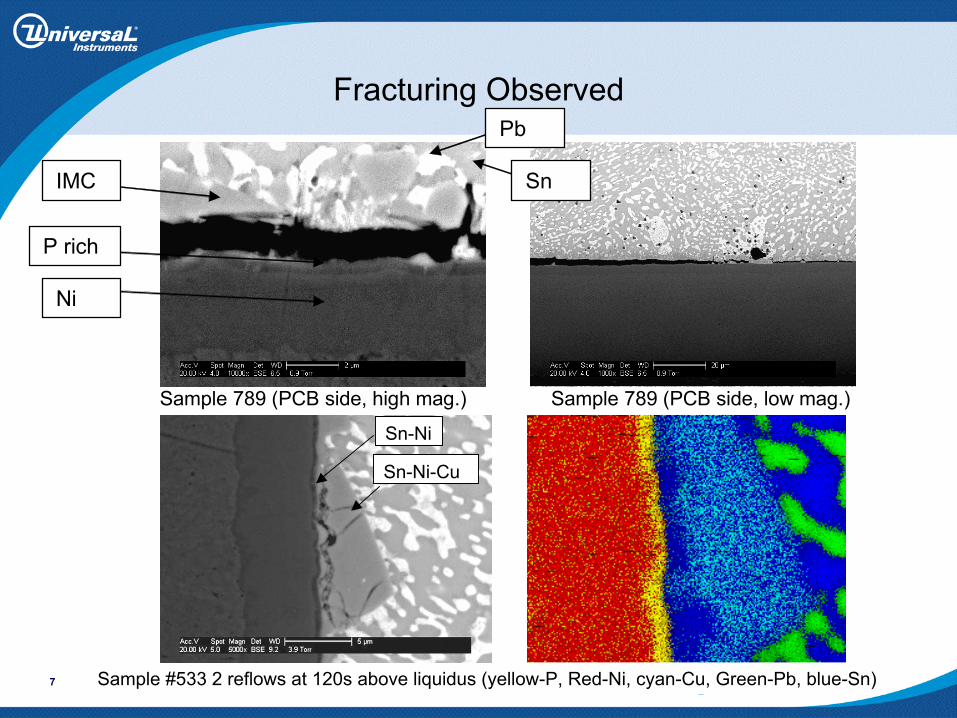
Fracturing Observed
Sample 789 (PCB side, high mag.) Sample 789 (PCB side, low mag.)
IMC
P rich
Ni
Pb
Sn
Sample #533 2 reflows at 120s above liquidus (yellow-P, Red-Ni, cyan-Cu, Green-Pb, blue-Sn)
Sn-Ni
Sn-Ni-Cu

8
Pad Fracture Surface
9
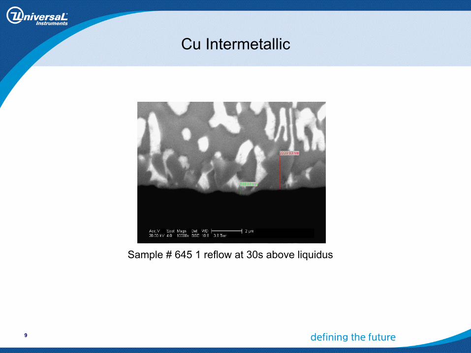
Cu Intermetallic
Sample # 645 1 reflow at 30s above liquidus

10
Second Assembly with Similar Failure Mode
• 20 mil ball vs. 30 mil ball• Profile:
– 50, 60, & 70 seconds above 183C• Little change to brittle failure mode
70 sec above 183°C sample
60 sec. above 183°C sample
Mapped area of bulk solder
Cu Map
Cracks in intermetallic region
11
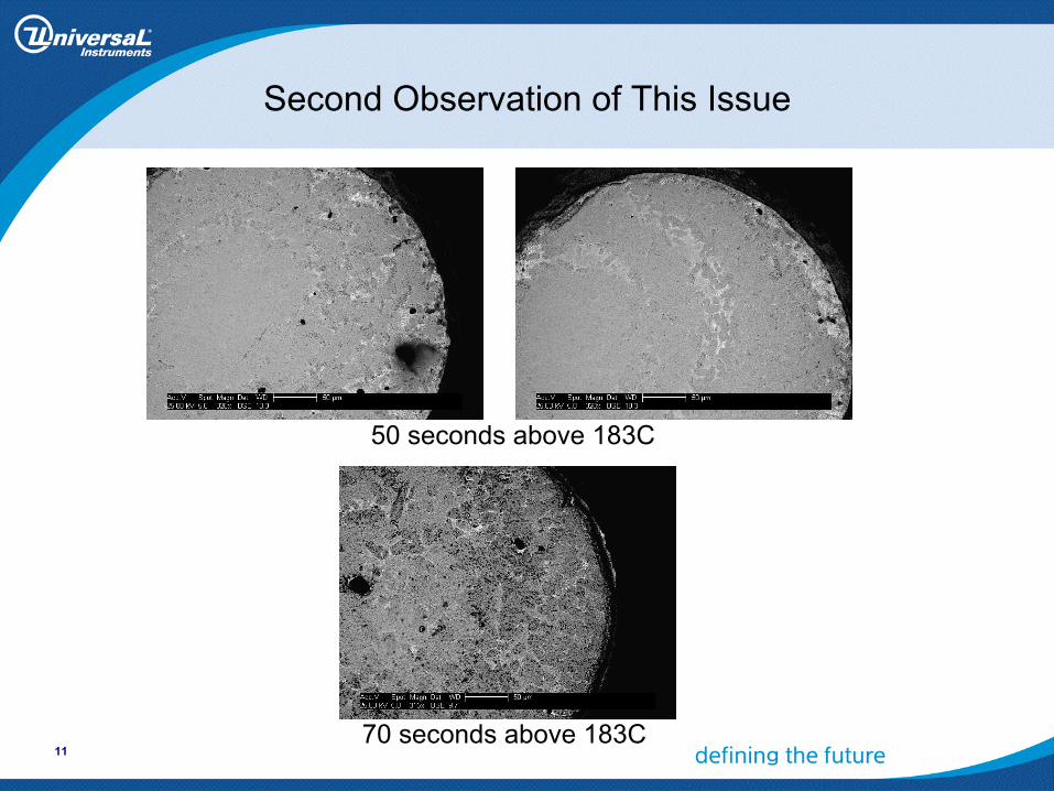
Second Observation of This Issue
50 seconds above 183C
70 seconds above 183C
12
Observations and Unknowns
• Condition of ENIG on component and Cu on PCB is not unusual in this industry.
• Dependence on thermal profile appears clear.• Components do not exhibit brittle condition as-received or attached to ENIG
PCBs.
• Is (Cu,Ni)6Sn5 formation on these component types unusual?• Can Cu dissolution rates effect the percentage of Cu in the bulk solder?
– In other words is this a Cu plating issue rather than a Ni issue?• Does this failure mode present a significant concern?
– This failure mode appears more susceptible to mechanical stress– Customer pry tests may cause qualification issues– We have observed some sporadic brittle issues on high I/O BGA
devices with these metallurgical combinations.• What Ni condition could exacerbate this issue?• Are micro-fractures being formed due to mismatch of IMC CTE or density