thermal conduction heating for in-situ thermal desorption of soils
TRANSCRIPT

THERMAL CONDUCTION HEATING FOR IN-SITU THERMAL DESORPTION OF SOILS
by
George L. Stegemeier and
Harold J. Vinegar
Reprinted with permission from Hazardous & Radioactive Waste Treatment Technologies Handbook, Ch. 4.6-1, Oh, Chang H. (Ed.)
Copyright 2001, CRC Press, Boca Raton, Florida.

A-1
THERMAL CONDUCTION HEATING FOR IN-SITU THERMAL DESORPTION OF SOILS
by George L. Stegemeier GLS Engineering, Inc.
and Harold J. Vinegar
Shell E&P Technology Applications and Research Co.
ABSTRACT In-Situ Thermal Conduction Heating is a soil remediation process in which heat and vacuum are applied simultaneously to subsurface soils, either with surface heater blankets or with an array of vertical heater/vacuum wells. Radiation heat transport dominates near the heaters, which are operated at 800 to 900°C; however, thermal conduction accounts for most of the heating at greater distances into the soil. As soil is heated, contaminants in the soil are vaporized or destroyed by a number of mechanisms, including (1) evaporation into the air stream, (2) steam distillation into the water vapor stream, (3) boiling, (4) oxidation, and (5) pyrolysis. The vaporized water, contaminants, and natural organic compounds are drawn by the vacuum in a direction countercurrent to the heat flow into the vacuum source at the blankets or wells. Compared to fluid injection processes, the conductive heating process is very uniform in its vertical and horizontal sweep. Furthermore, transport of the vaporized contaminants is improved by the creation of permeability, which results from drying and shrinking of the soil. Flow paths are created even in tight silt and clay layers, allowing escape and capture of the vaporized contaminants. The combined effectiveness of both heat and vapor flow yields nearly 100% sweep efficiency, leaving no area untreated. Furthermore, the contaminants in the heated soil are almost completely removed, with a displacement efficiency approaching 100%. This occurs because the entire treatment zone may be heated to high temperatures (in some cases, greater than 500°C) for many days. Laboratory treatability studies and field project experience have confirmed that the combination of high temperature and long time results in extremely high overall removal efficiency of even the high boiling point contaminants. In practice, most of the contaminants are destroyed in the soil before reaching the surface. Contaminants that have not been destroyed in-situ are removed from the produced vapor stream at the surface with an air pollution control system. The vapor treatment train consists of a thermal oxidizer, heat exchanger, carbon bed absorbers, and vacuum blowers. With this system, destruction and removal efficiencies in excess of 99.9999% have been achieved in the stack effluent. Several field research demonstrations and a number of field remediation projects at contaminated sites have been carried out by TerraTherm Environmental Services, Inc. Both thermal blankets and thermal wells have been proven to be highly effective in removing a variety of contaminants including polychlorinated biphenyls (PCBs), pesticides, chlorinated solvents, and heavy and light hydrocarbons.

THERMAL CONDUCTION HEATING FOR
IN-SITU THERMAL DESORPTION OF SOILS
by George L. Stegemeier GLS Engineering, Inc.
and Harold J. Vinegar
Shell E&P Technology Applications and Research Co.
Houston, Texas INTRODUCTION In-Situ Thermal Conduction Heating is a soil remediation process in which heat and vacuum are applied simultaneously to subsurface soils. In the past decade, it has been applied at a number of sites, and the process has been described in several patents and publications.1–11 In remediation applications, it is sometimes referred to as “In-Situ Thermal Desorption”(ISTD). ISTD has been used in various modes including surface heating with blankets, subsurface heating with an array of vertical heater/vacuum wells, and ex-situ blankets. Radiation heat transport dominates near the heaters, which are operated at 800 to 900°C; however, thermal conduction accounts for most of the heating at greater distances into the soil. As soil is heated, contaminants in the soil are vaporized or destroyed by a number of mechanisms, including (1) evaporation into the air stream, (2) steam distillation into the water vapor stream, (3) boiling, (4) oxidation, and (5) pyrolysis. The vaporized water, contaminants, and natural organic compounds are drawn by the vacuum into the blankets or wells in a direction countercurrent to the heat flow. Compared to fluid injection processes, the conductive heating process is very uniform in its vertical and horizontal sweep, evenly heating the entire volume of soil. Furthermore, transport of the vaporized contaminants is improved by the creation of permeability, which results from drying and shrinking of the soil. Flow paths are created even in tight silt and clay layers, allowing escape and capture of the vaporized contaminants. The combined effectiveness of both heat and vapor flow yields nearly 100% sweep efficiency, leaving no area untreated. Furthermore, the contaminants in the heated soil are almost completely removed, with a displacement efficiency approaching 100%. This occurs because the entire soil zone can be heated to high temperatures for many days. (If needed, soil may be heated to temperatures greater than 500°C.) Laboratory treatability studies and field project experience have confirmed that a combination of high temperature and long time results in extremely high overall removal efficiency of even the high boiling point contaminants. In practice, most of the contaminants are destroyed in the soil before reaching the surface. Contaminants that have not been destroyed in-situ are removed from the produced vapor stream at the surface with an air pollution control system. The basic vapor treatment train consists of a thermal oxidizer, heat exchanger, carbon bed absorbers, and vacuum blowers. With this system, destruction and removal efficiencies (DREs) in excess of six nines (99.9999%) have been

3
achieved in the stack effluent, with combined in-situ and aboveground DREs as high as 99.9999998% having been demonstrated.
The thermal conduction processes have been studied in laboratory and full-scale field research tests at Shell’s Gasmer Road Field Research Facility in Houston, Texas,1,5,8 and at General Electric’s Corporate Research and Development Center in Schenectady, New York.2,3 Both thermal wells and thermal blankets have been demonstrated to be highly effective in removing from soils a wide variety of low and high boiling point hydrocarbons, PCBs, pesticides, and chlorinated solvents. ISTD processes have been applied commercially at several contaminated sites by TerraTherm Environmental Services, Inc. (TESI)4,6,7,9,10,11,19 The operations were fast, clean, quiet, and odorless and caused little disruption of adjoining neighborhoods. In every case, the projects were successfully completed, and the residual contaminants were well below the remediation goals.
In January, 2000, the Thermal Conduction Technology was donated by Shell Oil Company to The Center for Petroleum and Systems Engineering at The University of Texas in Austin. The commercial license has been granted to TerraTherm, LLC.12 DESCRIPTION OF PROCESS The thermal conduction process can be used to heat soil for either in-situ or ex-situ remediation. In either application, it can be carried out on large volumes of contaminated materials in a single batch. The heat is injected either from areal surface blankets or from vertical or horizontal wells. See Figure 1. Thermal blankets are effective for surficial contamination down to about 3 feet, and thermal wells can be placed to virtually any depth. The fundamental processes, including heat flow, fluid flow, phase behavior, and chemical reactions, are similar for each method. In each case, heat is applied to a soil from a high-temperature surface in contact with the soil, so that radiation heat transfer is effective near the heater, and thermal conduction and convection occur in the bulk of the soil volume. Thermal conduction accounts for over 80% of the heat transfer. A significant feature of the process is the creation of a zone of very high temperature (>500°C), which causes destruction of many contaminants before they exit the soil. Thermal Blankets
Surface heating and vacuum extraction as an in-situ process for removing contaminants from surface and near-surface soils is achieved by evacuating the soil under a flexible, impermeable sheet and heating the soil surface up to as much as 900°C with a relatively flat electric blanket heater. See Figure 2. In commercial field application, thermal blanket modules (each 8 ft x 20 f t x 1 ft) are configured in groups to cover part or all of a site. Each module is a stainless steel box that contains (1) heating elements that are spaced about 3 inches apart in a furnace belt, and (2) a layer of vermiculite insulation. An impermeable, flexible sheet covers a group of modules and serves as the vapor seal. Modules contain vapor ports that are connected by a manifold system to the Process Trailer, where unreacted contaminants are oxidized or absorbed from the vapor stream. Each heat treatment of the soil requires 2 to 10 days, depending on the desired depth of treatment, water content of the soil, and other factors. With average soil conditions, about 500 watts/square foot of surface can be injected initially, declining to about 300 watts/square foot after several weeks of heating.

4
The heat flows downward by radiation and thermal conduction, and the consequent increase in soil temperature results in removal of contaminants from the soil by a number of mechanisms, including boiling, evaporation, steam distillation, pyrolysis, oxidation, and other chemical reactions. Contaminant vapors or volatile decomposition products are convected by the vacuum to the surface, where they are collected into the vapor treatment facility. At remediation sites where a large amount of water vapor is produced, it is sometimes preferable to maintain 100% vapor phase throughout the vacuum treatment system. In other applications, it may be more economic to trap liquids in condensers and treat a smaller stream of vapors. When a flexible vapor seal is used rather than a rigid module box, the differential pressure between the atmosphere above the flexible sheet and the vacuum under the sheet presses the sheet, insulation, and heater firmly against the soil. This improves conformance with the surface and increases thermal contact of the heater with the soil. The impermeable sheet may extend areally beyond the surface heater. In this peripheral region, the vacuum seals the sheet directly against the soil. Thus, air, moisture, and contaminants in the soil below the heater are pulled almost vertically to the surface. Atmospheric air, which enters the soil from outside the impermeable sheet, is also produced. Entry of outside air into the central vacuum system is restricted, however, since the air must travel some distance horizontally through the soil. The flow of air through the high-temperature soil serves to evaporate and oxidize contaminants in-situ, thereby supplementing the boiling and steam distillation mechanisms. Thermal Wells For soil contamination at depths greater than 3 feet, heating with surface blankets is ineffective and thermal wells are needed to attain high temperatures in the soil. The principle of in-situ thermal desorption with heater/suction wells is shown in Figure 3. A standard arrangement is a regularly spaced array of heaters emplaced in screened holes in the soil. The space between wells at the surface is covered with an impermeable sheet that enables a vacuum to be imposed by the wells on the entire targeted soil region. In most applications to date, vertical wells are used; however, slanted or horizontal wells offer attractive alternatives for remediation under buildings, foundations, roads, or other inaccessible areas. The vertical wells are installed on a triangular grid, typically with a spacing of 5 to 7 feet between wells. Several considerations affect the choice of spacing. First, the well spacing should not exceed the thickness of the heated interval, in order to avoid excessive heating above and below the target interval. Second, the well spacing, not the length of heated interval, determines the time required to heat the formation. The time required for a project is proportional to the square of the spacing, since each well has a nearly fixed power input, but must heat the soil in the hexagonal element of symmetry surrounding it. Third, the amount of power needed to heat the soil is determined by the soil type and moisture content. Fourth, the type of contaminant to be removed determines the temperature to which the soil must be heated. Using a well spacing of 5 feet, soil can be heated to >500°C in 30 to 40 days. Well spacing for thick contaminated zones can be considerably greater if lower temperatures are needed or if longer times are permitted The heater/vacuum well illustrated in Figure 4 is typically configured in a 6 inch diameter hole with (1) a 10-20 mesh sand-filled annulus between the soil face and the well casing/liner, (2) a 4 in. or 4.5 in OD stainless steel slotted (0.032 in. x 2 in.) and screened (40 mesh) liner, (3) a 2.5 in. OD pipe sealed at the bottom to provide a “heater can” to isolate the heater element from the product stream, and (4) Nichrome wire heater elements threaded through ceramic

5
insulators. The heaters normally extend 2 feet above and 2 feet below the contaminated layer of soil in order to apply full temperature to the targeted interval. In addition, to compensate for heat losses at the upper and lower boundaries, these 2-foot intervals are designed to deliver about 25% more power per linear foot than does the rest of the heater. This can be accomplished by adding an extra parallel heater or changing the Nichrome wire diameter (e.g., from 0.128 in. to 0.114 in.). At the surface, the well casing is cemented in the soil and is also sealed to the heater can, thereby providing an annular space in which to apply a vacuum to the well. Thus, the heater/vacuum well provides a means of injecting heat into the soil and countercurrently collecting vapors into the well. Wells may be completed either as heater/vacuum wells or heater-only wells. Heater-only wells are simply configured with a casing pipe that serves as the “heater can,” with the heater elements inside. Because the heater wells do not have countercurrent flow of vapor, they can inject more heat into the soil than do the heater/vacuum wells. One useful triangular array forms a series of hexagonal patterns, with a combination vacuum/heater or production well in the center of each hexagon surrounded by six heater-only wells. See Figure 5. This arrangement of wells is permitted when the producing capacity of the single producer is sufficient to capture vapors generated by all of the associated heater wells. Electric heater wells were originally developed for use at depths up to 2,000 feet for enhanced oil recovery; however, for ISTD remediation projects, the wells are usually less than 100 feet. Depth alone is not a limitation for application of ISTD; however, inflow of groundwater usually increases with depth. Where the recharge rate of groundwater into the site is greater than the boiling rate of the electric well heaters, the soil temperature cannot be raised above 100°C. In order to dry the soil and reach superheat temperatures in these cases, it will be necessary to control the water influx with temporary bulkheads, freeze walls, or de-watering, Before beginning heating in a remediation project, it is advisable to produce any liquids that can be pumped or drawn by vacuum from the screened wells. If the target layer is high in the vadose zone, or if the layer is a tight silt or clay, very little liquid will be produced; however, if there is active groundwater flow, it is essential to determine its extent before initiating heating. Groundwater can enter a remediation site from the edges, from the bottom, or from the top. Because horizontal permeability is almost always greater than vertical permeability, the edge-water influx can be the most troublesome. Vertical inflow is usually impaired by even thin clay layers; however, because the area available to inflow is larger than that at the sides, it is still of concern. Inflow from the top can be prevented by proper drainage design of the impermeable sheet covering the area. Often groundwater problems are seasonal, and in those cases, the project should be scheduled to avoid the rainy season. It is more economical to lift out liquid water by pumping than by boiling and producing it as vapor because of (1) the cost of electrical energy to boil the water, and (2) the increased operating costs resulting from the longer time required to reach the process temperature in a wet soil. Start-up of a remediation begins by imposing a vacuum on all of the screened wells with the vacuum blower. The vapor flow rate will be determined by the soil permeabilities and geometrical factors. The object of imposing the vacuum during heating is the capture of vapors that are generated and of any air that is drawn through the soil. A rule of thumb is that one standard cubic foot of vapor flow per minute is needed for every kilowatt of power injected. Common well headers and subsurface probes may be monitored to confirm that negative pressures are maintained on the heated soils throughout the remediation.

6
Thermocouples may be placed within the heater wells to control the power input and to monitor the performance of the heating elements. If well controllers are used, a high rate of electrical power is injected until the heater elements reach their maximum operating temperature. As the soil around the wells is heated, the maximum allowable power input slowly decreases. At heater temperatures of 1400 to 1600°F, the wells initially can inject about 500 watts/ft, declining to about 300 watts/ft over a period of weeks. Another mode of heating is to set the well heaters at the lower limit of power input so that they will not exceed the maximum allowable temperature during the life of the project. Designs for injecting heat without well temperature control are simpler to install and operate, but require somewhat longer times for heating. The progress of the heat-up of the soil between the heater wells is monitored with thermocouple wells. For triangular patterns, the thermocouples are generally located at the centroid of the triangular area. This location is the most distant from the heaters; consequently, it is expected to be the coldest spot. For sites as deep as 10 feet, thermocouple wells usually can be installed by driving a 1-inch OD, stainless-steel pipe into the soil. The pipes are sealed at the bottom and open to the atmosphere at the top, allowing temperature logging with traveling thermocouples during the heating operations. Heating at the thermal wells is continued until the target temperatures (based on contaminant properties) are reached at the coldest point between the wells. The temperature history of the soil consists of three periods: heat-up, boiling water, and superheating, as shown in Figure 6. During the first period, the soil minerals and fluids (mainly water) are heated to the boiling point of water. This heat-up is fairly rapid, especially if the soil is fairly dry, since the heat capacity of silicate and carbonate minerals is small. During the second period, the temperature stays at the boiling point until all the pore water is boiled off. The duration of this phase depends on the amount of pore water to be boiled; if additional groundwater flows into the target zone during heating, the boiling time is extended even further. When all the water has been vaporized, the dry soil can be superheated. During this third period, the soil temperature rise is even more rapid than during the first period, since only the soil minerals remain to be heated.
Figure 7 shows the actual temperature history of soils at 6 feet depth measured during an ISTD demonstration at the Missouri Electric Works Superfund site in Cape Girardeau, Missouri. The twelve thermocouples shown in Figure 7 were located at the centroids of twelve adjoining triangles with a 5-ft well spacing. The first (heat-up) phase lasted about 250 hours; the second (boiling) phase ended between 560 and 630 hours, with the center and adjoining triangles drying first and the outer triangles later. During the third (superheating) phase, soil temperatures rose rapidly until the heaters were turned off on day 42 (1000 hours). Maximum temperatures over 1000°F were reached at the centers of the triangles, and about 50% of the volume was over 1100°F.
As soil temperatures increase, water, volatile organic compounds (VOCs), semivolatile organic compounds (SVOCs), PCBs, petroleum aromatic hydrocarbons (PAHs), and volatile metals contained in the soil matrix are volatilized by the dynamic heat front and drawn to the wells by the vacuum. If air is present, the contaminants are rapidly oxidized in the hot soil near the heating elements where temperatures typically exceed 1,000°F. Remaining contaminants in the product stream (which is composed primarily of air, water, and oxidation products) are drawn through the manifold system to the Process Trailer for further treatment.

7
Ex-Situ Remediation Using Thermal Conduction Heating At many sites, contaminated soil has already been excavated or stockpiled. At other
sites, small amounts of widely scattered contaminants can be more easily gathered to a single location for treatment rather than dealt with separately in the ground. In these cases, it is more effective to modify the ISTD system and use thermal conduction heating at the surface.
Unlike other ex-situ processes that are carried out in reactors where residence times are only a few seconds or minutes, the modified in-situ thermal conduction heating allows treatment times ranging from hours to many days. These longer times are permitted because large volumes can be treated at one time. Thus, heating the interior of large, metallic objects, lumps of soil, concrete, etc., which is a particularly troublesome problem for batch reactors, is easily accomplished by ISTD. Furthermore, irregularly shaped metal objects, vessels, or pipes do not require metal shredding, as is required in conventional thermal desorption reactors or incinerators. Because the permeability of the soil is increased by the high-temperature drying, contaminants can be efficiently removed from even tight clays.
Another advantage of applying thermal conduction heating at the surface is the ease of positioning the heaters in the dirt pile. Heaters can be installed as the soil is being accumulated so the heating times can be minimized. For example, blanket heaters can be placed both at the top and at the bottom of a layer, or horizontal wells can be placed in shallow trenches.
The flexibility of the ISTD thermal well and thermal blanket system allows it to be adapted to many types of ex-situ operations. It has been used in a remote location, where the aboveground process equipment was skid-mounted and shipped as a complete unit. Figure 8 shows an ex-situ remediation on the island of Saipan in the Northern Mariana Islands.
ISTD is essentially a ‘closed loop’ system that eliminates the negative aspects of ex-situ operations including the noise, dust, fumes, odors, and material sorting that are inherent in ex-situ activities. Most on-site, batch-based systems aggravate these material handling problems due to the limitations on the amount that can be treated at a time, requiring constant loading and unloading, as well as increased sampling activities. Potential Applications for Thermal Conduction Heating Because thermal conduction is such a simple means of evenly heating the soil, it offers a variety of uses in soil remediation. Some of these applications are: 1. In its simplest form, widely spaced electric heaters could be driven into the ground to warm
the soil slowly over a period of months and thereby optimize temperature for bio-remediation of degradable contaminants. Warming to 30 or 40 oC would be especially helpful in cold regions where biological activity is low.
2. In the next level of complexity, driven heaters can be used in conjunction with Soil Vapor Extraction in several different modes: a. Thermally assisted soil vapor extraction (TSVE) can shorten project life and provide
complete clean-up in conventional SVE projects. For example, with conventional vapor extraction wells at service stations, dry-cleaning shops, or industrial sites contaminated with chlorinated solvents or fuels, heat injection from driven heaters will accelerate vaporization of contaminants and result in completion of the projects in weeks rather than years.
b. In another version, the conventional vapor extraction wells can also be heated to prevent condensation.

8
c. Thermally assisted dual phase extraction (TDPE) is still another application in which contaminants are extracted from soil in both liquid and vapor phases.
3. In the conventional use of thermal conduction heating, both heat and vacuum are applied in the manner described throughout this paper to volatilize and destroy or recover contaminants in the vapor phase. Thermal vacuum heating has the potential of complete containment and complete recovery of the contaminants. A wide variety of materials may be treated. a. Volatile organic compounds, including gasoline and chlorinated solvents such as
trichloroethene (TCE) and tetrachloroethene (PCE), can be removed at medium temperatures (100° to 200°C). Semi-volatile compounds, such as PCBs, dioxins, MGP wastes, will require higher temperatures (200° to 400°C).
b. Although not field tested, inorganic contaminants such as mercury, arsenic, antimony, and cadmium, and their compounds are also potential targets for removal or conversion to other less volatile or less water-soluble compounds.
c. Mixed wastes (those containing a combination of radionuclides and chlorinated hydrocarbons, carcinogens, etc.) present special challenges, but the thermal conduction/vacuum process is effective in removal of the volatile organic components and may reduce the water solubility of the radionuclides.
d. Contaminants heavier than water, also referred to as dense, non-aqueous-phase liquids (DNAPLs), when they have migrated below the water table into aquifers, may also be amenable to recovery by thermal conduction heating. If the water influx precludes complete vaporization, the DNAPL may be at least partly removed by steam distillation or by reduction in the liquid-phase viscosity.
4. In deep soil contamination, it may be acceptable to carry-out thermal conduction processes under a positive pressure rather than with a vacuum. If an active water drive provides containment, the heating and steam distillation could be carried out without significant migration of the contaminant. This method might be visualized as a controlled steam drive, with perfect sweep, not limited by areal or vertical heterogenieties of the soil.
Costs The cost of thermal conduction remediation, using the applications described above, will vary greatly, depending on the contaminant type and the level of remediation required. Factors that affect costs per ton of soil include size of the project site , cost of electricity , control of water recharge, depth of contamination, and air discharge limits. In almost all cases, simply injecting heat with electric heaters will be cost competitive with other in-situ thermal processes. The conventional ISTD thermal/vacuum process was designed with the assumption that contaminants should be removed from sites, not just dug up and put somewhere else, or capped with a temporary seal. A further assumption was that acceptable levels of contaminants remaining after treatment must be extremely low to meet environmental regulatory requirements. Furthermore, there were rigid constraints to avoid scattering the contaminants or other unwanted effects. With these ground rules, we concluded that remediation by full, high-temperature in-situ thermal conduction heating with vacuum and complex vapor treatment was the only process that would meet all of these requirements. TerraTherm has estimated the cost of such a complete process would be in the range of $50 to $250/ton of soil. Additional improvements and efficiencies in the process are expected to reduce these costs.

9
PROCESS AND CONTROL EQUIPMENT
Process and control trailers are connected to the heating modules and the vapor collection manifold to deliver and control electrical energy to the heating elements contained within the modules and to treat the vapor stream before venting to the atmosphere. Process trailer components include a cyclonic particle separator, a HCl scrubber, a thermal oxidizer, an air-to-vapor heat exchanger, carbon canisters, discharge blowers, back-up generator, control cabin, thermal monitoring system and continuous emission monitoring system (CEM). See Figures 9 and 10.
Process Trailer Operations Process gases removed from the heated soil (primary treatment) typically contain greatly reduced concentrations of original contaminants, oxidation products, water vapor, and atmospheric gases. For example, soil contaminated with chlorinated hydrocarbons will produce CO2, H2O, HCl, and small amounts of unreacted contaminant. If the soil naturally contains sufficient carbonates, HCl scrubbing may not be needed. The produced gas stream then receives its initial treatment on the process trailer in the flameless thermal oxidizer (secondary treatment). This operation generates conditions sufficient to reduce residual contamination concentrations in the recovered gas stream by four nines (99.99%) of destruction or more. When combined with oxidation processes occurring in the subsurface, over six nines (99.9999%) destruction is typically achieved. A high-efficiency thermal oxidizer is not always necessary. For VOCs or non-chlorinated SVOCs, a regenerative thermal oxidizer capable of 95% DRE followed by adsorption on activated carbon often provides sufficient treatment of the recovered gas stream
Heat Exchanger and Carbon Beds Effluent from the flameless thermal oxidizer passes through a cooler to reduce temperatures prior to carbon adsorption (tertiary treatment). Two carbon beds in series provide redundant adsorption of recovered process gases. When carbon bed adsorption is combined with in-situ and thermal oxidizer treatment, over eight nines (99.999999%) destruction has been achieved. Process blowers maintain negative pressure on the soils being treated and pull the gas stream through the secondary and tertiary treatment processes on the trailer. This feature prevents uncontrolled atmospheric emissions, in that small leaks anywhere in the treatment train upstream of the vacuum blower will flow into the stream rather than escape to the atmosphere.
Air Emission Controls The process vapor stream is monitored continuously. This Continuous Emission Monitoring (CEM) utilizes an extractive sample probe and conditioning system. The sample stream is analyzed with a non-destructive infrared analyzer for CO and CO2. O2 is measured using a zirconium oxide detector, and Total Hydrocarbons (THC) are measured using a flame ionization detector. CEM data are collected electronically and displayed graphically. The data are stored using computer software and can be retrieved at any time.
Stack Emissions Stack emissions are sampled during operations following EPA methods and procedures and analyzed to specific quality assurance and quality control criteria. Emission samples are collected from two sample points; the first is collected after secondary treatment at the post-oxidizer, pre-carbon position, and the second is collected downstream of the carbon beds (this second sample is representative of the actual stack emissions).
Electrical Power Generator and Safety Controls Once the soil has been heated, it is essential that a vacuum be maintained throughout the rest of the remediation. In the event of a power outage, emergency generators kick in to maintain power to the thermal oxidizer and

10
blowers to assure that gases are processed through the oxidizer and carbon beds. Heater power to the thermal blankets or wells is then automatically shut down to prevent the generation of additional gases.
Control System The overall process system is controlled by a supervisory programmable logic controller (PLC) located within the control room of the trailer. A visual monitor displays operating status of system components to the operator through a personal computer. An example of a visual display of the status of a project is shown in Figure 11. In addition to system control, the operator’s computer provides extensive data logging and graphing capabilities. The temperatures of the blankets and wells are monitored continuously using Inconel-sheathed thermocouples. This information allows the operator to control blankets or wells individually, if desired. If blanket or well heaters exceed the set operating level, an alarm sounds and the specific blanket or well is shut down. Throughout the air treatment process, vapor stream temperatures are monitored and recorded, with vapor flow rates monitored continuously using in-line analog meters. Vacuum pressure is measured continuously using Magnahelic gauges, and the temperatures within the oxidizer are monitored continuously using thermocouples. In the event of thermocouple malfunction, the system identifies the defective component, which is then replaced or repaired. The flow rate of combustion air is monitored to ensure that excess oxygen is emitted by the oxidizer. Heat exchanger temperatures are monitored at the hot and cold sides of the stream and tied to the process control system. The temperature and circulation rate of the air in the exchanger are adjusted to control the temperature of the vapor stream feeding the carbon beds to ensure efficiency and safety. REMOVAL MECHANISMS Heat Flow
Radiation Heat flow mechanisms in thermal/vacuum soil remediation processes are a combination of radiation, conduction, and convection. Although conduction heating accounts for most of the heat flow in the soil, radiation is important in transferring heat from the heater elements to the containment sheet or pipe. Efficient radiation requires temperatures greater than 600°C, but has the advantage of instantaneous transfer across empty space. See Appendix Equation (12). This characteristic can be utilized to spread heat evenly at the irregular soil surface under a thermal blanket or to increase the initial area to conductive flow into the soil around the thermal wells. In the latter case, a large-diameter casing allows better heat injectivity of the well. Conduction Because thermal conduction in soils is relatively slow acting, the application of heat can be closely controlled. Most remediation operations are carried out under transient heat flow conditions; that is, temperature at a given location changes with time. Since these changes occur very slowly, an operator can safely remediate soil near buildings or underground utilities. For example, thermal blankets have been placed less than a foot from foundations without overheating, and thermal wells, located inside buildings, have been used successfully a few feet from sewer or water lines. Heat flow by conduction has been described mathematically, both for blankets (linear flow13 downward into the soil) in Appendix Equations (5) and (6), and for wells (radial flow14,15 outward from the well casing) in Appendix Equations (7)–(10). These calculations predict a very fast temperature fall-off near the heat source, especially for radial flow from wells. For example, after a month of heating, a single heater well can scarcely raise the soil temperature to 500°F only 3 feet away (Figure 12). Fortunately, interwell temperatures reflect the superposition of thermal fronts

11
from all of the heaters in the patterns. See Equation (11). This results in a temperature peak close to each well, but a more uniform temperature rise over the rest of the soil pattern. (See Figure A-3.) Interwell soil temperatures become even more uniform after long times of heating. Initially, power input is held constant until the heater reaches its maximum temperature, usually in less than one day. If soil properties are uniform and constant, initial temperature changes can be approximated by the constant-power, line-source, exponential integral solution.14,15 Thereafter, a constant heater temperature is maintained by decreasing the power to the heaters. Temperatures around a constant-temperature cylindrical source are described by the Bessel function solution. Convection As evidenced by the propagation of thermal fronts away from typical ISTD heat/vacuum sources when vapors are being drawn into the source, convection heat transfer is smaller than conduction heat transfer. An exception to this occurs when large amounts of groundwater or air enter the target soil from outside the heated region. Thermal diffusion-driven, high-temperature convection of vapors is another mechanism tending to disperse heat, smoothing the heat fronts. In practice, in addition to the simple conduction/convection mechanisms discussed above, the actual temperature rise is also affected by the change in thermal conductivity of the soil as it dries and by latent enthalpy changes due to water evaporation and condensation. In addition, the temperature dependence of the thermal properties, and the effects of non-uniform geology, add complexity that is best understood with numerical simulators. Shell’s numerical simulator for oil reservoirs (THERM) has been modified for environmental applications and was used to design the initial commercial projects. As actual field experience has been acquired, the need for detailed numerical simulations has lessened, and average soil properties and temperature can be used in the design of most projects. Details of the energy balance, which determines the heating time, are given in Appendix Equation (29). Vaporization and Phase Behavior Depending on the process temperature, several mechanisms can contribute to the vaporization of liquids and solids in thermal conduction soil remediation. Contaminants having boiling points ranging from that of benzene (B.P. 80°C) to that of dibenzo(a,h)anthracene (B.P. 524°C) have been successfully removed by the process. Vaporization mechanisms are closely related to vapor pressure, which increases regularly with temperature. (See Figure 13.) Evaporation If a flowing stream of air or water vapor is present, it is not necessary to raise the temperature to the boiling point of a compound in order to vaporize it. An increase in the vapor pressure increases the mole fraction of a component in the vapor phase, as approximated by Dalton’s and Raoult’s Laws. (See Equations (13) and (16).) For heavy, high-boiling-point compounds, an increase in vapor pressure to only a few millimeters of Hg pressure will result in hundreds of parts per million in the vapor phase. See Equation (15). Thus, substances that normally are not considered volatile can be evaporated in a stream of air that is only mildly heated. Because the masses of flowing air and water are usually much larger than that of the contaminants in the ground, large amounts of even heavy contaminants can be removed in the vapor stream. Steam Distillation Water is almost always a major component of soils in the subsurface. As temperature is increased to the boiling point of water (100°C), steam distillation of immiscible compounds occurs. Steam is a more effective evaporant of heavy organic compounds than air because of steam’s lower molecular weight. (See Equation (18).)

12
Furthermore, the higher temperature (and higher vapor pressure) of the contaminants provides a richer contaminant fraction in the vapor stream. Boiling Even if an evaporant, such as air or water vapor, is not present, increasing the temperature to 300°C results in vaporization of most organic compounds by simple boiling. At these higher temperatures, thermal diffusion is the only transport mechanism available after all of the lower-boiling connate compounds have been produced. Therefore, some convection of outside air or in-flow water vapor is useful in transporting the remaining high-boiling-point contaminants through the soil to the vacuum source. Chemical Reactions At the highest temperatures, oxidation and pyrolysis become important vaporization and destruction mechanisms. Products of chemical reactions, with the exception of coke, are more volatile than are the original organic compounds. In-Situ Transport of Contaminants A critical requirement of any remediation process is the efficient transport and collection of the contaminants in the soil. Although contaminants can be vaporized by the heating, potential gradients need to be provided and effective flow paths need to be created to transport the fluids out of the soil. Vacuum Effects Maintenance of a vacuum is an important feature of the thermal conduction process. The imposition of a vacuum in the heated region of the thermal conduction process not only provides a gradient for flow, but also offers other advantages. Negative pressure in the heated region prevents pressure-driven gradients from spreading the contaminants outside the treatment volume, since the other physical flow mechanisms such as capillarity and diffusion also direct flow into the heated region. Imposing a vacuum on heater wells prevents the pressure rise that can occur near a heated well, thereby avoiding escape of vapors to the atmosphere. The liquids in the soil are volatilized by the temperature increase and drawn into the heater/vacuum wells countercurrently to outward heat flow. This flow arrangement also exposes all of the flowing contaminants to high reaction rates in the high-temperature regions near the heater wells. See Equations (19)–(22). Flow into the hot heater-vacuum wells can yield high in-situ destruction efficiency (90 to 99%) and minimize the amount of treating needed in surface facilities. Vapor-Phase Flow/Recovery Another important feature of the thermal conduction process is the opportunity of heating the soil above the boiling point of water, thereby creating a continuous vapor-phase flow regime. The production vapor stream consists of (1) air drawn in from outside the heated zone and from the lesser amount originally in the pores of the vadose zone, (2) water vaporized from pore liquid water in the soil and any groundwater drawn in from outside the heated region, (3) vaporized organic compounds, either naturally occurring or contaminants, and (4) gas-phase combustion products from oxidation and pyrolysis of organic components. All flow in the heated region occurs in the vapor phase except for peripheral groundwater influx and a small amount of capillary wicking into the heated regions. Creation of a continuous gas phase throughout the soil provides high-relative-permeability flow paths for removal of contaminants. By vaporizing the last bits of residual liquids, the process also avoids capillary trapping of residual liquid phases that occurs in all of the multiphase flow processes. This feature distinguishes thermal conduction heating from other remediation processes in that it permits complete removal of contaminants.
Creation of Permeability Still another feature of thermal conduction processes is the creation of permeability in the heated, dry regions of subsurface formations. This is important because steam and other vapors that are generated when soils are heated will build positive

13
pressures unless the soil has sufficient permeability to allow the vapors to be withdrawn by an applied vacuum. The permeabilities required to prevent pressure buildup are quite high. For example, Equation (30) predicts that a permeability of 1 darcy is needed to produce the vapors generated by a 900°C heat source with a vacuum of 10 inches of water. Many natural soils, such as clays and silts, are almost impermeable to fluid flow (< 1 millidarcy); however, heating these soils sufficiently to dry them greatly increases the pore permeability and, in some cases, creates a secondary network of high-transmissibility fractures that allows effective transport of the vapors over long distances. The creation of polygonal fractures by the shrinkage of the hydrated minerals, such as clays, is a well-known phenomenon that can be observed at the surface of dry lake beds. Typically, the frequency of these fracture polygons in dry mud is of the order of 1 foot and the width of fractures is as much as 1 inch. Assuming the development of a similar fracture network in the subsurface, we might expect a flow path sequence consisting of a few inches of high-temperature diffusive flow out of the polygons into the fractures and then many feet of convective flow along the fractures to the wells. Even in formations that do not have much shrinkage upon drying, a small local buildup of pressure is sufficient to lift the overburden soil slightly, thereby increasing porosity or creating minute horizontal fractures to the wells.
Experience in field operations has verified that vacuum can be maintained over considerable distances in dry soils, even when a large amount of water vapor is being generated. When vacuum is applied at every heat source, the increase in permeability in the soil occurs faster than the propagation of the boiling front, and no pressure buildup is observed.
In some cases, heat may be applied to the soil at locations that do not have a coincident vacuum. For example, a hexagonal heater well pattern with a single heater/vacuum well at the center of the hexagon may be used. See Figure 5. When mixed well patterns are used, care must be taken to develop permeability with the heater/vacuum wells before full power is applied to the heater-only wells. A reduced rate of heating may be applied initially to the heater-only wells until permeability is created by the drying.
An alternative design may be used in which the heater-only wells are sealed at the surface under an impermeable barrier. In that case, permeability is developed in the region immediately around the heater. This local permeability increase provides a vertical flow path for the vapors produced by heater-only wells to escape to the surface. There, they may be collected by a vacuum applied to a permeable layer.
Thermal conduction is the only process capable of uniformly drying the formation and heating above the boiling point of water. In view of the adverse experience with soil vapor extraction (SVE) in low-permeability silts and clays, the creation of permeability by thermal conduction drying may be the most critical improvement needed for SVE remediation.
In summary, the ability of thermal conduction heating to achieve dryness and superheat satisfies the requirements for complete vaporization and transport of contaminants via vapor phase to the extraction wells. Chemical Reactions In addition to the physical changes in contaminant properties that occur with increases in temperature, a number of chemical changes are also known to occur in these compounds. Products of these chemical reactions are usually more volatile than the original contaminants; hence they are more easily vaporized. With even gentle warming, biological activity in soils will increase and promote destruction of organic compounds. Generally, chemical reactions at low temperatures are not

14
expected to be useful in batch treatments of contaminants; however, in the in-situ thermal processes, where the residence time of reactants is sufficiently long, some of these reactions become important. Oxidation of hydrocarbons and chlorinated hydrocarbons is known to be effective at very high temperatures, but can destroy contaminants even at low temperatures if the residence time for reaction is large. We can reasonably expect a considerable amount of oxidation of contaminants during heating in the 100° to 200°C range, since slow oxidation of most organic compounds in air occurs at room temperature, and hydrogen-rich hydrocarbons will spontaneously combust at temperatures above 300°C. In thermal conduction remediation projects, a large amount of air can be drawn through the soil and be made available for these reactions. At higher temperatures (>550°C), even carbon-rich compounds can be oxidized, and pyrolysis will occur in the absence of air. Both oxidation and pyrolysis of contaminants produce volatile compounds that can be more easily mobilized in the vapor phase. Pyrolysis also deposits inert solids such as “dead” carbon that can be safely left in the soil. The gas flowing out of the soil typically contains water vapor, carbon dioxide, and HCl (when chlorinated organic contaminants are present), plus any unreacted components from the soil. See Equations (23)–(25). In addition to air oxidation, the reactions of organic compounds with water are well known in the production of “water gas” at very high temperatures. Hydrous oxidation reactions have been proposed as a potential method for destroying contaminants at moderate temperatures in in-situ thermal remediation processes.16 In all thermal conduction remediation projects, a large amount of naturally occurring water is available for such reactions. Not much quantitative information is available on chemical reaction as a means of destroying contaminants in thermal remediation; however, in the treatability studies discussed in the next section, a significant disappearance of high-boiling-point compounds is observed well below their boiling points. TREATABILITY STUDIES Contaminants A variety of contaminants have been examined as to their suitability for remediation from soils by the thermal conduction process. These include (1) light hydrocarbons, — benzene, toluene, xylene, and the gasoline range distillates; (2) light chlorinated hydrocarbon solvents — TCE, PCE, DCE, etc.; (3) insecticides — chlordane, lindanes (α-,β-,γ-,δ), 4,4′-DDT, 4,4′-DDE, and 4,4′-DDD; (4) high-boiling-point hydrocarbons — diesel, lube oils, and tar; (5) heavy chlorinated hydrocarbons — including polychlorinated biphenyls (PCB-1248, PCB-1260), dibenzo-dioxins (TCDD and OCDD), and dibenzo-furans (TCDF); and (6) manufactured gas plant (MGP) wastes. The removal occurs either by vaporizing and collecting them in the vacuum system or by destroying them in the ground.
Treatability Tests Treatability tests were devised to determine the temperature and time required for removal of contaminants from soil samples taken from prospective remediation sites. Several kinds of tests were considered, including a heating/convection test with flow through of air or water vapor; however, a simple heating test with the soil sample in a ceramic crucible has proven adequate for design of field projects. The treatability tests were carried out by placing soil samples in uncovered crucibles and heating them in a muffle oven.8 The treatment temperatures were chosen based on the boiling points of the primary constituents of concern. The temperatures were increased over a period of several hours and then held constant at the desired treatment temperature for 1 to 3 days. Pre-

15
and post-treatment analyses were performed to determine the initial and final concentrations of contaminants. Treatability Results Although the treatability tests are not scaled to field dimensions and do not replicate the convective mechanisms operative in the field, they appear to be a reasonable guide for field behavior. Table 1 is a summary of some results of these tests together with results from pre- and post-treatment sampling at field remediation project sites. The results clearly show that contaminants are removed from soils at temperatures considerably below their boiling points. This would not be surprising if the removal mechanism were only evaporation, since efficient drying of water occurs almost 100°C below its boiling point. Because there are a number of vaporization mechanisms that can be operative, the removal of contaminants from soil is more complex. Soil mineral surfaces are known to tenaciously hold a “recalcitrant“ fraction of contaminants, and desorption appears to be time dependent.17 As shown in Figure 14, compounds boiling in the range of 400–480°C are largely removed by heating to 400°C for 1 day, but they are even more effectively removed by heating to 300°C for 3 days. Every compound that has been studied can be removed from soil by heating for only a few days. Concentrations of benzene in coal tar were reduced from 39,000 µg/kg initially to only 22 µg/kg after as little as 1 day of heating at 200°C. Benzo(a)-pyrene and other PAHs boiling in the range of 500–525°C were reduced by a factor of 10,000 as a result of heating 3 days at 300°C. See Figure 15. Field projects typically maintain even higher temperatures for longer periods of time; consequently, they can be expected to attain better destruction efficiency. FIELD PROJECTS In addition to an active field research and development program at Shell’s Gasmer Road Field Research Facility in Houston, Texas,1,5,8 there have been a number of field remediation demonstrations2,3,4,6,7 and commercial field projects9,10,11,19 at contaminated sites. ISTD has been used in a number of modes (surface heating, heating from wells, ex-situ blankets, coincident heat/vacuum sources, and separate heaters and vacuum sources). A wide variety of high- and low-boiling-point contaminants have been remediated in these and other projects (Table 2). A few of these field projects will be reviewed to show the range of applications. MISSOURI ELECTRIC WORKS (PCBS) Both thermal wells and thermal blankets have been demonstrated to be highly effective in removing PCBs from soils. In a field demonstration at the Missouri Electric Works (MEW) Superfund site in Cape Girardeau, Missouri, ISTD thermal blankets and wells were shown to remediate high-concentration PCB contamination from shallow and deep clay soils.6–7 The MEW site was contaminated with PCBs in both shallow and deep soils during past operations that included servicing and remanufacturing transformers, and recycling dielectric fluids containing PCBs. The natural stratigraphy is brown clay soil; the water table is located about 40 feet below ground surface. The objectives of the MEW field test were (1) to clean up clay soils contaminated with high concentrations of the highest-boiling-point PCB, Aroclor 1260, to less than 2 ppm, (2) to demonstrate that stack discharges were in compliance with state and federal standards for PCBs and polychlorinated dibenzodioxins/polychlorinated dibenzofurans (PCDDs/PCDFs), and (3) to obtain a system DRE for PCBs greater than 99.9999%. The demonstration was conducted in

16
support of TerraTherm Environmental Services’ application for a modification of the TSCA permit for alternate PCB treatment. EPA Region VII and the Missouri Department of Natural Resources (MODNR) monitored the demonstration.
For the blanket demonstration, two heater blankets were placed side-by-side in an area where PCB concentrations had averaged 510 ppm near the surface and 2.7 ppm at 12–18 inches. The target treatment depth was 18 inches.
For the well demonstration, twelve heater/vacuum wells were completed in a multiple triangular array with a 5-foot well spacing to a depth of 12 feet. The area chosen had PCB contamination as high as 19,900 ppm near the surface and still above 2 ppm at the target depth of 10 ft. During the demonstration, electrical heating and vacuum were applied to the wells for a period of 42 days.
In the blanket demonstration, the soil was successfully remediated to a depth of 18 inches. The upper 1 foot of soil was non-detect for PCBs (i.e., < 33 ppb) and averages at all depths met the remedial objective of < 2 ppm.
In the well demonstration, temperatures above 1000°F were achieved in the interwell regions. Maximum temperatures over 1000°F were reached at the center of the triangles, and about 50% of the volume was over 1100°F. Sampling after 42 days showed complete clean-up of all contaminants to levels below 1 ppm to a depth of 10 ft below ground surface. Eighty-one samples in the treatment zone were non-detect (< 33 ppb) by EPA Method 8080. Sampling down to 15 ft in the center of the treated zone showed that no vertical migration of contamination had occurred.
Emission stack sampling by EPA methods demonstrated that the discharge of PCBs and combustion byproducts complied with state and federal ambient air requirements. Stack testing of emissions from the process indicated 99.9999998% DRE of the PCBs by combined in-situ and surface treatment. The sampling and analysis results of the EPA Method 680 analysis performed on the stack samples indicate that a total of 0.10 mg of PCB was emitted from the stack from a conservative estimate of 40 kilograms of PCB in the treated area.
Post-treatment soil samples composited vertically and areally from the treated zone were analyzed for PCDD and PCDF and exhibited 2,3,7,8-tetrachlorodibenzodioxin equivalent (TEQ) levels from non-detect to 6.84 parts per trillion, with an average of 3 ppt. This is below the background level of 8 ppt for uncontaminated soil in North America. CENTERVILLE BEACH, CALIFORNIA (PCBS)
A commercial PCB remediation utilizing 53, 15-ft deep heater wells was successfully performed at a Navy base at Centerville Beach, California. Residual PCB levels below 1 ppm were achieved in all target zones. PORTLAND, INDIANA (CHLORINATED SOLVENTS)
The first full-scale commercial application of ISTD was performed by Shell Technology Ventures Inc. at a Shell site in Portland, Indiana.9–10 (See Figure 16.) The site contained difficult-to-remediate, tight clay soils contaminated with high concentrations of tetrachloroethene (PCE) to depths as great as 18 feet. The size of the Indiana project included an area of about 6,500 sq. ft to a depth of 18 feet, or about 5600 tons. The impacted area was adjacent to and beneath a loading dock at a plastics manufacturing facility, which was located across the street from a residential neighborhood. (See Figure 17.) At the Indiana site, as at many other sites,

17
there is a wide variation in permeabilities ranging from tight clays to the high-permeability fill located above the target zone. A large amount of surface run-off water at the site drained into the vadose zone above the normal water table at 22 feet. Water influx during heating was partially controlled with perimeter drains.
This area was treated with 130 vacuum/heater wells on 7.5-foot triangular spacing, including 26 wells that had to be drilled through the concrete loading dock to remediate the underlying soil. The site was successfully remediated by reducing initial concentrations of PCE that were as high as 3,500 ppm to less than the Tier 2 Industrial Standards established for the site (< 8.01 ppm for depths greater than 2 feet). In fact, after thermal treatment, all samples below 2 feet had less than 0.5 ppm of PCE remaining.
A separate smaller area (30 x 20 ft) of 1,1-dichloroethene (1,1-DCE) contaminated soil at the same facility was also treated successfully with 18 vacuum/heater wells installed on 7.5-foot spacing to depths of 12 feet. The entire site was remediated in-situ without disruption to the adjacent residential neighborhood from noise, dust, and odors that would have likely been associated with alternative remedial options such as excavation.
Before the heating was discontinued, soil samples were taken with a hollow sampling probe at the coldest locations (centroids of the triangular patterns) furthest from each heater well. These were analyzed and used to decide whether additional heating was required. The sampling data, temperature profiles, and absence of HCl in the stack were all used to determine when remediation was complete. For quality assurance, confirmatory samples were taken after heating when the soil had cooled below 100°F.
After the remediation operation was completed, the wells were removed and the holes were grouted to the surface. After the winter, new grass growth reappeared naturally, without re-seeding. Later, revegetation was accelerated by resodding, and after one year the site was completely restored. No damage was observed to the nearby trees. EUGENE, OREGON (DIESEL AND BENZENE)
The largest ISTD field project to date was a ¾-acre Shell diesel loading facility in Eugene, Oregon.11 This site had free-product LNAPL (diesel and gasoline with benzene). Hydrocarbon contamination was observed in cores to depths of 12 feet. The lithology was gravel and sand fill above silty sands, with a water table that varied seasonally from 5 ft depth to 12 ft depth.
The project utilized 761 wells, with an ISTD well pattern that included hexagonal heater-only wells surrounding center heater-vacuum wells. (The ratio of heater-only wells to heater-vacuum wells was 2 to 1.) A ring of dewatering wells was used to control the water influx. A visual display of the Eugene project heater wells from the computer display inside the instrument truck is shown in Figure 11. About one-fourth of the heater wells were drilled inside buildings through the concrete floors. The wells also extended down an alley way adjacent to apartment buildings and straddled a sewer line in the alley way.
The site was heated for 110 days, utilizing 4.5 Mw of electric power. During the heating, some 250,000 pounds of organic compounds were removed from the soil. After the remediation, sampling wells showed no remaining free product, and all samples were non-detect for benzene.

18
SAFETY In-Situ Thermal Desorption operations have been carried out by TerraTherm
Environmental Services Inc. with careful attention to safety and health of on-site operators and nearby residents and with concern for the long-term impact of operations on the environment. Enclosed by fencing, the operations were so clean, quiet, and trouble-free that normal activities of nearby businesses and residents were continued with scarcely any interruption.
In future ISTD projects, attention to safety is of continuing importance. Because the process uses large amounts of electrical power and high temperatures, it is essential to keep a high profile on safety with active management controls of ongoing activities and with continuing education of site personnel. As expected with all new technologies, a number of concerns have been expressed by regulators and site owners. These have been addressed by TESI’s R&D efforts as follows: Underground Fires
Ignition of hydrocarbons and other organic materials in soils during heating by the ISTD Process was examined to assess the possibility of uncontrolled subsurface fires. Typically, the oxidation reactions take place in porous soils that consist of about 60% by volume of rock minerals (either silicates or carbonates) and 40% pore space. The large amount of rock minerals absorbs reaction energy, so that even for a soil laden with 10,000 ppm THC (total hydrocarbons), complete combustion would raise the temperature to only about one-half of a flame temperature. To burn that much hydrocarbon would require hundreds of pore volumes of air. In practice, the amount of air present in the pore space of even a dry vadose zone is sufficient to burn only about 20 ppm of the THC, and that amount of combustion would raise the soil temperature only a few degrees. These are the reasons sand is used to extinguish fires.
Underground fires associated with coal mines occur because of oxygen supplied by the coal itself and the presence of large mine shafts that can convect large amounts of air. In soil remediation, uncontrolled fires are not likely, and if oxidation ever became excessive, it could easily be quenched by drawing water into the soil with the vacuum. Migration of Contaminants Theoretical and numerical simulation studies have indicated that ISTD can be used to remove contaminants from a region of subsurface soils without dispersion of contaminants beyond the boundaries of the treated zone. One reason for this is the negative pressure imposed by the vacuum wells in the soil that draws the mobilized contaminants inward. Because of continued questions on this matter, TESI made a large effort to detect migration in our field experiments and demonstrations. None of these investigations found evidence of migration after a completed thermal treatment. The reason for this is the abruptness with which the temperature falls off with distance from the heat sources. In large projects, the potential edge dispersion zone is miniscule compared to the dimensions of the treated zone. Contaminants naturally migrate due to subsurface flow of water driven by hydraulic gradients. Removing this influence by de-watering, and removing the source of the plume by superheating with ISTD, prevents further migration. Formation of Toxic By-Products The question of whether dioxins and furans are formed in the wells as by-products of the ISTD may be addressed by noting that the reaction rate of formation is slower than the destruction rate of a by-product at the process temperatures of the heaters through which all of the products pass. In addition, by-products have comparable volatility to the original compounds

19
so that even if they had been formed in the soil, they would be vaporized and drawn to the wells. Aside from these theoretical arguments, we have proven in field experiments that dioxins or furans remaining after thermally treating PCB-contaminated soils were less than the average concentration in uncontaminated soils in North America.6 Fugitive Emissions Toxic stack emissions in the field projects are typically two orders of magnitude below EPA’s ambient air criteria. This is a result of the in-situ destruction, highly efficient thermal oxidizers, and final carbon-bed absorbers. The escape of fugitive emissions at the edge and at the surface of the treated soil is prevented by a combination of an impermeable sheet covering the surface and the imposition of a vacuum on the entire region. Verification of the absence of escape of contaminants was carried out at field sites. Details of these results may be found in Reference 6. Fate of Buried Drums Many sites contain wastes that had been placed in sealed drums and buried in shallow ditches. Typically these drums corrode after a few years and no longer present any hazard of over-pressuring when heated. To investigate the potential problem with new sealed drums, we conducted field tests on new 30-gallon drums, crimped at the ends and sealed with conventional rubber-gasketed bungs. The drums were filled with liquid ethanol and buried, standing vertically and lying horizontally, two feet below the surface. These drums were heated by several nearby heater wells, and the ethanol was successfully remediated from the drums without any event recorded on a nearby seismometer. The experiment was repeated with the bungs welded in. At about 100 psi internal pressure, the vertical drum failed and blew out the overburden two feet of sand. These experiments demonstrated the hazard of tightly sealed vessels that might build sufficient pressure to fail and erupt at the surface. As a precautionary measure, buried drums near the surface could be perforated with a driven rod. Deeply buried drums will leak at the crimped ends before building sufficient internal pressure to burst and crater. A hazardous condition exists at any site containing unexploded ordnance or high-pressure gas bottles. At suspected sites, detailed location of metallic objects with ground-penetrating detectors will be required, and during remediation, the site area must be shielded and isolated from personnel. DISCUSSION After ten years of development and field applications, thermal conduction heating with vacuum extraction is now a technically mature soil remediation process. Being versatile and robust, it has met or exceeded remediation goals at every contaminated site where it has been used. The reason for this success is that, although simple in concept, thermal conduction heating has a number of unexpected advantages for soil remediation:
(1) Thermal conduction heating from high-temperature heaters allows large amounts of heat energy to be injected without fluid injection. Avoidance of fluid injection is an important advantage in that the entire subsurface region being heated can be maintained at sub-atmospheric pressure, thereby preventing spreading of contaminants to surrounding regions.
(2) The injection of heat energy by thermal conduction is very uniform compared to convective heat flow. The high sweep efficiency results from the regularity of areal patterns of heat injection wells and the uniformity of heat flow into the variable layers of natural soils.

20
Thermal conductivities of dry soils differ by a factor of only about two for various soil types. In contrast fluid flow permeabilities of sedimentary layers may vary by a factor of 100,000,000. Furthermore, unlike fluid flow, heat flow is self correcting, since thermal conductivity decreases with an increase in temperature, whereas, permeability increases with displacing phase saturation. Use of electric heaters allows heat to be injected exactly where it is needed over the vertical profile. The net result is that the entire volume of contaminated soil can be heated to a desired process temperature, regardless of variability in the subsurface geology.
(3) Because the soil can be heated to high temperatures, the process is effective in recovering any contaminant that can be volatilized. The high displacement efficiency results from the nature of the vaporization in the microscopic pores of the soil. Several mechanisms contribute to the vaporization of contaminants. If soil is heated to the boiling point of a contaminant, it is readily mobilized in the vapor state; however, even heating below the boiling point increases the vapor pressure of the contaminants and permits evaporation into a carrier stream of air that may be drawn in by the vacuum. Steam distillation is even more effective in vaporizing the contaminants. Most natural formations contain large amounts of liquid water compared to contaminants. Boiling this pore water provides a water vapor stream that is an important means of volatilizing the contaminant. If air is present when contaminants pass through soils that have been heated, they are destroyed in-situ by oxidation. At higher temperatures (>350°C), air oxidation is nearly instantaneous, and even reactions with water occur. In the absence of air and water at these high temperatures, the contaminants are altered by pyrolysis to form more volatile compounds. The overall result is that low- and high-boiling-point contaminants are all efficiently volatilized and made available for vapor-phase transport. Treatability studies of soil samples in the laboratory have shown that removal of contaminants from soils can be a function of both temperature and time. Unlike ex-situ thermal processes, the in-situ processes have very long residence times, which are favorable to the removal mechanisms that might be time dependent. Heating times for natural soils are necessarily longer than vaporization or desorption times; thus, complete removal can be achieved if the soil is heated to an adequate temperature, which is nominally the boiling point of the contaminant.
(4) Another important feature of the in-situ thermal conduction process is the creation of permeability in heated dry regions of subsurface formations. The increase in permeability allows the process to be applied to low-permeability clays and silts where other processes cannot be used effectively. The major increase in microscopic permeability can occur in soils when the pore water is evaporated. In addition, the drying of a layer of clay-rich soil creates a polygonal network of wide cracks. Such a drainage network would explain the effective removal of contaminants out of dried silt/clay soils that is observed with widely spaced wells in field projects.
The ability of thermal conduction heating to achieve dryness and to superheat the soil fulfills both process requirements essential for perfect remediation: complete vaporization of contaminants and effective transport via vapor phase to the extraction wells.

21
ACKNOWLEDGEMENTS A large number of people in Shell, General Electric, RT Environmental, Woodward–Clyde, Haley & Aldrich, Metcalf & Eddy, Hart Crowser, ENSR, and TerraTherm Environmental Services participated in the development of thermal conduction heating. With the certainty that we will be omitting many who worked on these projects, we wish to recognize the contributions to the technology and to the contents of this review of F.G. Carl, L.J. Bielamowicz, K.L. Tschiedel, E. deRouffignac, W.A. Edelstein, R.B. Sheldon, G.R. Brown, W.B. Silverstein, S.R. Blaha, J.M. Hirsch, D.S. Christensen, P.D. Uhlman, R.L. Rosen, J.L. Menotti, J.M. Coles, B.G. Hunsucker, E.M. Matuszak, K.S. Hansen, F.S. Mowat, Y. Deng, J.O. Reed, D.M. Conley, B.H. Snead, C.A. Whitaker, S.L. Walker, W.M. Savage, R.R. Burnett, H.F. Clough, and R.S. Baker. REFERENCES 1. Stegemeier, G.L. and Vinegar, H.J. (1995), “Soil Remediation by Surface Heating and Vacuum Extraction,” SPE 29771, SPE/EPA Exploration and Production Environmental Conference, Houston, Texas, March 27–29. 2. Iben, I.E.T, Edelstein, W.A., Sheldon, R.B., Shapiro, A.P., Uzgiris, E.E., Scatena, C.R., Blaha, S.R., Silverstein, W.B., Brown, G.R., Stegemeier, G.L., and Vinegar, H.J. (1996), “Thermal Blanket for In-Situ Remediation of Surficial Contamination: A Pilot Test,” Environmental Science and Technology, Vol. 30, No. 11, November, pp. 3144–3154. 3. Sheldon, R.B., Iben, I.E.T., Edelstein, W.A., Vinegar, H.J., de Rouffignac, E.P., Carl, F.G., Menotti, J.L., Coles, J., Hirsch, J.M., Silverstein, W.B., Blaha, S.R., Scatena, C.R., and Siegel, G.W. (1996), “Field Demonstration of a Full-Scale In Situ Thermal Desorption System for the Remediation of Soil Containing PCBs and Other Hydrocarbons,” HAZWaste World Superfund XVII, Washington, D.C., October 15-17. 4. Bay Area Defense Conversion Action Team, BADCAT (1997), Final Report for Environmental Technology Partnership (ETP) Demonstration, In-Situ Thermal Desorption, February. 5. Vinegar, H.J., Menotti, J.L., Coles, J.M., Stegemeier, G.L., Sheldon, R.B., and Edelstein, W.A. (1997), “Remediation of Deep Soil Contamination Using Thermal Vacuum Wells,” SPE 39291, 1997 Soc. Pet. Eng. Annual Technical Conference, San Antonio, Texas, October 5–8. 6. Vinegar, H.J., de Rouffignac, E.P., Rosen, R.L., Stegemeier, G.L., Bonn, M. M., Conley, D. M., Phillips, S.H., Hirsch, J. M., Carl, F.G., Steed, J.R., Arrington, D.H., Brunette, P.T., Mueller, W.M. and Siedhoff, T.E. (1997), “In Situ Thermal Desorption (ISTD) of PCBs,” HAZWaste World Superfund XVIII, Volume 2, pp. 453-462,Washington, D.C., December 2–4. 7. France–Isetts, P. (1998), “In Situ Thermal Blankets and Wells for PCB Removal in Tight Clay Soils,” CLU-IN: Tech Trends, EPA Region 7, February.

22
8. Hansen, K.S., Conley, D.M., Vinegar, H.J., Coles, J.M., Menotti, J.L., and Stegemeier, G.L. (1998), “In-Situ Thermal Desorption of Coal Tar,” IGT/GRI International Symposium on Environmental Biotechnologies, and Site Remediation Technologies, Orlando, Florida, December 7–9. 9. Baker, R.S., Vinegar, H.J., and Stegemeier, G.L. (1999), “Use of Thermal Conduction to Enhance Soil Vapor Extraction,” Contaminated Soils, Volume 4, pp. 39-58, edited by E.J. Calabrese, and P.T. Kostecki, Amherst Scientific Publishers, Amherst, MA. 10. Vinegar, H.J., Stegemeier, G.L., Stevenson, J.D., Carl, F.G., and Dudley, R.J. (1999), “In-Situ Thermal Desorption of Soils Impacted with Chlorinated Solvents,” Paper #99-450, presented at the Air and Waste Management Association Annual Meeting, St. Louis, June 22. 11. Conley, D.M., Hansen, K.S., Stegemeier, G.L., Vinegar, H.J., Fossati, F.R., Carl, F.G., and Clough, H.J. (2000), “In-Situ Thermal Desorption of Refined Petroleum Hydrocarbons from Saturated Soil,” Proceedings of the 2nd International Conference of Remediation of Chlorinated and Recalcitrant Compounds, Physical and Thermal Technologies, pp. 197-206, Edited by Wickramanayake, G.B. and Gavaskar A.R., Battelle Press, Columbus, OH, May 23. 12. TerraTherm LLC, 356-B Broad Street, Fitchburg, MA 01420, www.terratherm.com. 13. Carslaw, H.S. and Jaeger, J.C. (1959), “Conduction of Heat in Solids,” Second Ed., Oxford Univ. Press, London, p. 261. 14. Ibid, p. 335. 15. Abramowitz, M. and Stegun, I.A. (1965), Handbook of Mathematical Functions, Dover Publications, New York, p. 231, Eqn. 5.1.54, Ref. C. Hastings, Jr., Note 143, MTAC 7, 68 (1953). 16. Newmark, RL., Aines, R.D., Leif, R., and Knauss, K., (1998), “Thermal Treatment: Dynamic Underground Stripping and Hydrous Pyrolysis Oxidation,” paper presented at the EPA Technical Innovation Office Seminar on In-Situ Thermal Treatment, Atlanta, GA, December 16. 17. Uzgiris, E,E., Edelstein, W,A., Philipp, H.R., and Iben, I.E.T. (1995), “Complex Thermal Desorption of PCBs from Soil,” Chemosphere, Vol. 30., No. 2, pp. 377–387. 18. Stegemeier, G.L. (1998), “Design Equations for In-Situ Thermal Desorption,” presented at the U.S. EPA, Technical Innovation Office Seminar on In-Situ Thermal Treatment, Atlanta, GA, December 16. 19. Conley, D.M. and Lonie, C.M. (2000), “Field Scale Implementation of In Situ Thermal Desorption Thermal Well Technology.”, Physical and Thermal Technologies: Remediation of Chlorinated and Recalcitrant Compounds, pp. 175-182, Edited by G.B. Wickramanayake and A.R. Gavaskar, Battelle Press, Columbus, OH.

TABLE 1
SUMMARY OF TREATABILITY TESTS AND FIELD PROJECTS
TYPE / TREATMENT
BEGINNING CONCENTRATION
ENDING CONCENTRATION
MATRIX
OCDD 6.9 ppb 0.014 ppb Silty Clay Chlordane 1 day, 200°°°°C 41 ppb < 0.033 ppb Sandy Silt 4,4′′′′-DDT 1 day, 200°°°°C 3,500 ppb < 0.033 ppb Sandy Silt Lindane 1 day, 200°°°°C 476 ppb < 0.066 ppb Sandy Silt 4,4′′′′-DDE 1 day, 200°°°°C 750 ppb < 0.033 ppb Sandy Silt 4,4′′′′-DDD 1 day, 200°°°°C 510 ppb < 0.033 ppb Sandy Silt PCB 1260 *Field ~500°°°°C 20,000 ppm ≤≤≤≤ 0.300 ppm Clay PCB 1248 *Field ~200°°°°C 5,200 ppm ≤≤≤≤ 0.950 ppm Sand 1,1-DCE *Field ~250°°°°C 650 ppb ≤≤≤≤ 0.53 ppb Clay TCE *Field ~250°°°°C 79 ppm < 0.005 ppm Clay PCE *Field ~250°°°°C 3,500 ppm < 0.005 ppm Clay Diesel *Field ~100°°°°C 9,300 ppm < 100 ppm Silt
MGP WASTE
BEGINNING CONCENTRATION
ENDING CONCENTRATION
1 day, 400°°°°C
ENDING CONCENTRATION
3 day, 300°°°°C Naphthalene 18,000 ppm < 0.033 ppm < 0.017 ppm Acenaphthylene 1,300 ppm < 0.033 ppm < 0.017 ppm Acenaphthene 750 ppm < 0.083 ppm < 0.042 ppm Fluorene 3,200 ppm < 0.083 ppm < 0.042 ppm Phenanthrene 7,600 ppm < 0.033 ppm < 0.017 ppm Anthracene 2,100 ppm < 0.033 ppm < 0.017 ppm Fluoranthene 4,500 ppm 0.091 ppm < 0.043 ppm Pyrene 3,700 ppm 0.160 ppm < 0.046 ppm Dibenzofuran 15 ppm < 0.033 ppm < 0.033 ppm Chrysene 1,300 ppm 0.200 ppm < 0.032 ppm Benzo (a) anthracene 1,000 ppm 0.130 ppm < 0.025 ppm Benzo (b) fluoranthene 960 ppm 0.410 ppm < 0.054 ppm Benzo (k) fluoranthene 390 ppm 0.140 ppm < 0.020 ppm Benzo (a) pyrene 1,100 ppm 0.360 ppm < 0.037 ppm Dibenzo (a,h) anthracene 44 ppm < 0.033 ppm < 0.017 ppm Benzo (g,h,I) perylene 690 ppm 0.570 ppm < 0.041 ppm Indeno (1,2,3-cd) pyrene 400 ppm 0.380 ppm < 0.071 ppm 1-Methylnaphthalene 2,700 ppm < 0.066 ppm < 0.033 ppm 2-Methylnaphthalene 8,000 ppm < 0.066 ppm < 0.033 ppm
( ≤ represents a detectable quantity where multiple samples were tested. )

TABLE 2
SUMMARY OF THERMAL CONDUCTION FIELD PROJECTS
LOCATION PROJECT SOIL TYPE DEPTH (feet)
PROCESS NUMBER OF BLANKETS-or WELLS
S. Glens Falls, NY Demo Sand 0 – 0.5 Blanket 5 – 8’ x 20’
Cape Girardeau, MO Demo Clay 0 – 1.5 Blanket 2 – 8’ x 20’
Cape Girardeau, MO Demo Clay 0 – 12 Wells 12
Mare Island , CA Demo Silt/Clay 0 – 14 Wells 12
Portland, IN Commercial Clay 0 – 12 Wells 15
Portland, IN Commercial Clay 0 – 20 Wells 130
Tanapag, Saipan Commercial Carbonate/Sand 0 – 2 Blanket Box 28 – 8’ x 20’
Eugene, OR Commercial Sand/Silt/Clay 0 – 11 Wells 761
Centerville Beach, CA Commercial Sand 0 – 15 Wells 53
LOCATION CONTAMINANT INITIAL CONCENTRATION
(ppm)
FINAL CONCENTRATION
(ppm) S. Glens Falls, NY PCB 1248/1254 5,000 < 0.8
Cape Girardeau, MO PCB 1260 500 < 1
Cape Girardeau, MO PCB1260 20,000 < 0.033
Mare Island , CA PCB 1254/1260 2,200 < 0.033
Portland, IN 1,1 DCE 0.65 0.053
Portland, IN PCE/TCE 3,500/79 < 0.5/0.02
Tanapag, Saipan PCB 1254/1260 10,000 < 1
Eugene, OR Gasoline/Diesel 3,500/9,300
+ free product
N.D. benzene 250,000 # free
product removed Centerville Beach, CA PCB 1254 800 < 0.17

Figure 1 Thermal Conduction Heati
POWER TRAILER
CONTROL TRAILER
VAPOR TREATMENT SYSTEM
THERMAL OXIDIZER
CYCLONE SEPERATOR
HEAT EXCH.
CARBON BED
EXHAUST STACK
BLOWERS
THERMAL BLANKETS
THERMAL WELLS
ng with Wells and Blankets

Figure 2 In-Situ Thermal Desorption with Thermal Blankets
Figure 3 In-Situ Thermal Desorption with Thermal Wells

Figure 4 Heater Vacuum Well Figure 5 Hexagonal Well Patterns

Figure 6 Theoretical Temperature Rise in Soil
Figure 7 Temperature Rise in MEW Triangular Patterns
Thermocouple at 50% Soil Volume
Thermocouples at Pattern Centroids
0
200
400
600
800
1000
0 10 20 30 40
HEATING TIME ( days )
AVE
RA
GE
TEM
PER
ATU
RE
( o F
)
Superheat
BoilingHeat-up
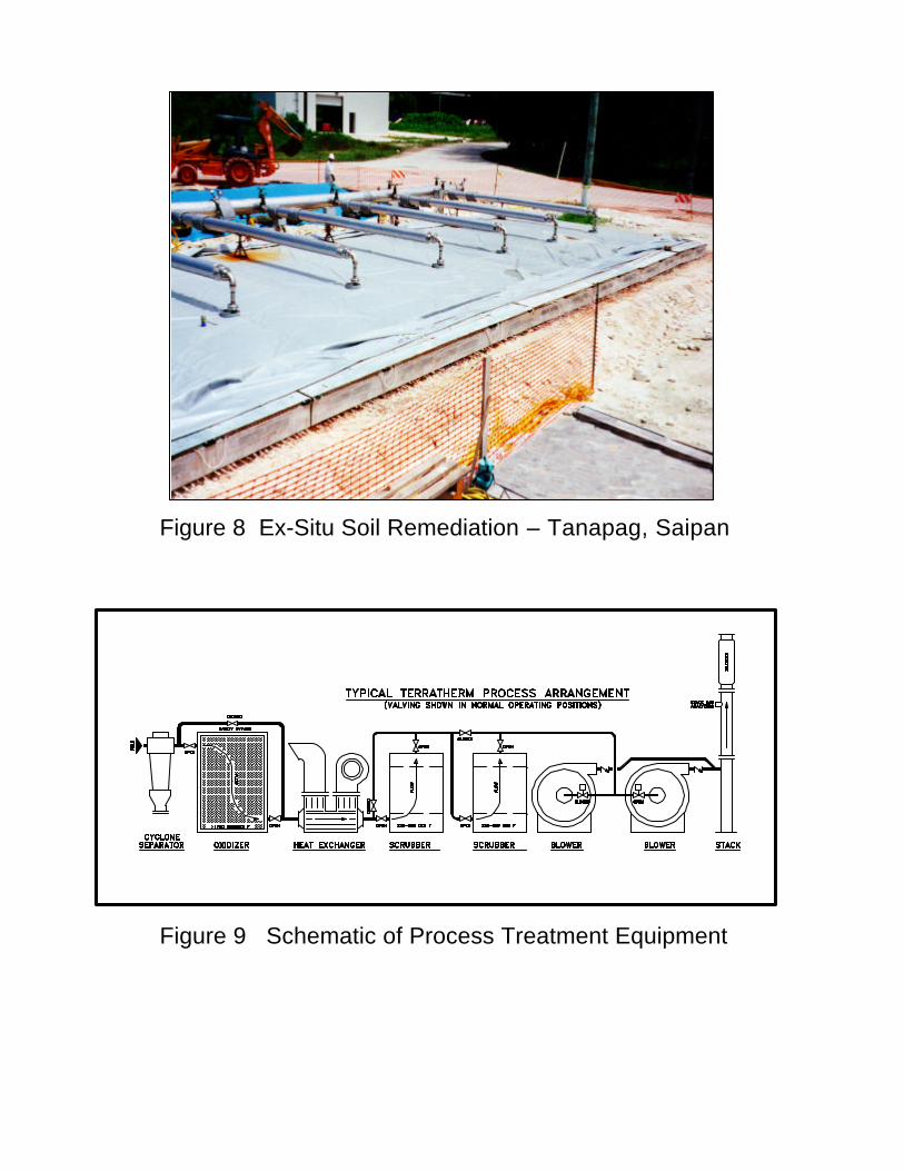
Figure 8 Ex-Situ Soil Remediation – Tanapag, Saipan
Figure 9 Schematic of Process Treatment Equipment

Figure 10 MU 1800 Process Trailer

Figure 11 Interactive Visual Display Eugene Project
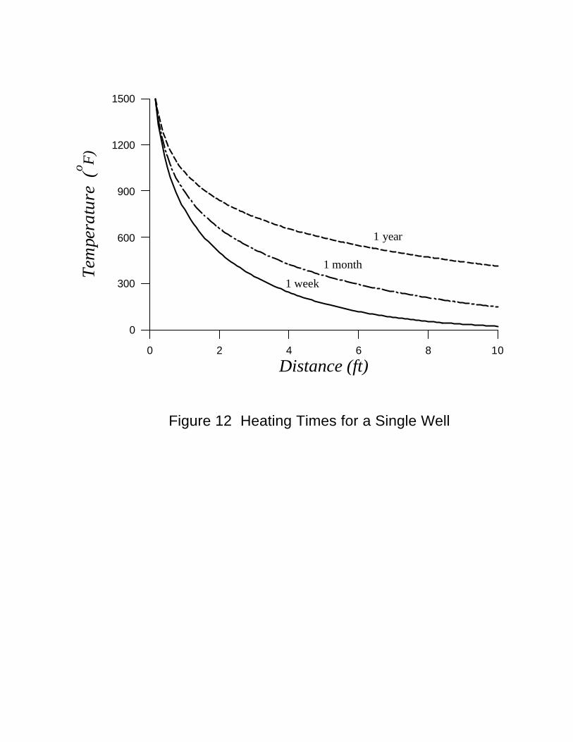
Figure 12 Heating Times for a Single Well
0 2 4 6 8 10
Distance (ft)
0
300
600
900
1200
1500Te
mpe
ratu
re (
o F)
1 week
1 month
1 year

1.E-07
1.E-06
1.E-05
1.E-04
1.E-03
1.E-02
1.E-01
1.E+00
1.E+01
1.E+02
1.E+03
1.3 1.5 1.7 1.9 2.1 2.3 2.5 2.7 2.9 3.1 3.3 3.5 3.7 3.91000/T [ 1000 / deg K ]
PRES
SUR
E (m
m H
g)
PCB 1242
TCDD Dioxin
PCB 1260
Water
Mercury
BenzeneTCE
Naphthalene
PCE
n-C16H34
n-C29H60
PCP
As
n-C10H22
Dieldrin
Pb Zn
TELB(a)Pyrene
CdCl2
As2O3
Sb
SbCl3
400 300 200 T oC 100 25 0760 mm
1.5 2.0 2.5 3.0 3.5 1000 / T ( 1000 / oK )
TEMPERATURE (oC)
400 300 200 100 25 0 760 mm
Figure 13 Vapor Pressure of Various Contaminants
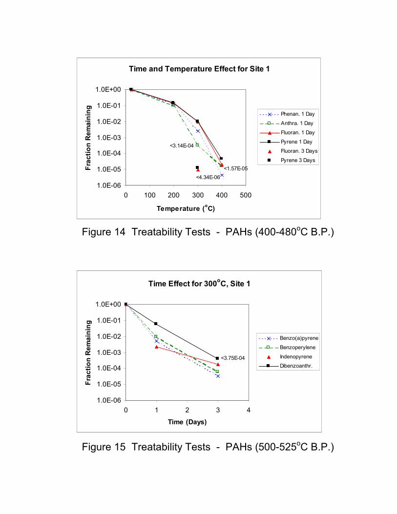
Figure 14 Treatability Tests - PAHs (400-480oC B.P.) Figure 15 Treatability Tests - PAHs (500-525oC B.P.)
Time and Temperature Effect for Site 1
<4.34E-06<1.57E-05
<3.14E-04
1.0E-06
1.0E-05
1.0E-04
1.0E-03
1.0E-02
1.0E-01
1.0E+00
0 100 200 300 400 500
Temperature (oC)
Frac
tion
Rem
aini
ng Phenan. 1 Day
Anthra. 1 Day
Fluoran. 1 Day
Pyrene 1 Day
Fluoran. 3 Days
Pyrene 3 Days
Time Effect for 300oC, Site 1
<3.75E-04
1.0E-06
1.0E-05
1.0E-04
1.0E-03
1.0E-02
1.0E-01
1.0E+00
0 1 2 3 4
Time (Days)
Frac
tion
Rem
aini
ng
Benzo(a)pyrene
Benzoperylene
Indenopyrene
Dibenzoanthr.

Figure 16 Portland, Indiana - Thermal Wells
Figure 17 Portland, Indiana - Remediation Site

A-1
APPENDIX
DESIGN EQUATIONS FOR IN SITU THERMAL DESORPTION18
The proper design of an In-Situ Thermal Desorption (ISTD) project depends on an
understanding of several mechanisms that occur in the soil during application of heat. These mechanisms are described by the fundamental equations that predict (1) fluid and heat flow, (2) vaporization and chemical reactions of contaminants, and (3) mass and energy balances. Although actual design computations are usually carried out in numerical simulators, the simplified analytical expressions, given below, will illustrate the in-situ process behavior. FLUID FLOW (Steady State)
Flow of fluids in a porous medium is described by a Darcy equation for each of the flowing phases. In most in-situ soil remediation processes, we need to account for flow of aqueous and oleic liquid phases and of a gas phase composed of air, water vapor, and lesser amounts of oleic vapors. The linear form of Darcy’s equation, as given in Equation (1), generally describes flow in the thermal blanket process. The radial form, as given in Equation (2), describes flow in the thermal well process.
In the Darcy equations, the soil properties (absolute permeability and porosity) are differentiated from fluid properties (viscosity and density). The interference of dissimilar fluids in multiphase flow is described by a relative permeability correction that is a function of the saturations of each of the phases. All properties may vary with temperature, and in this way the flow of viscous oil, water, and vapors is properly described throughout the entire process. HEAT FLOW Conduction (Steady State)
Heat flow by conduction in porous media is described by the temperature–heat flow equations that are similar in form to the pressure–fluid flow equations. For steady-state, linear, conductive heat flow, Fourier’s equation, given in Equation (3), is applicable. The Fourier equation for steady-state, radial, conductive heat flow is given in Equation (4). Conduction (Transient)
Because heat flow is so much slower than fluid flow, transient solutions are needed to describe this process. For linear flow, the rise in temperature as a function of time and distance from a plane heater blanket is given by Equation (5). This equation incorporates the bulk thermal properties of soil and the heat input rate per unit area of the heater. For pure conduction without convection, the temperature fall-off with distance is described by the complementary error function as given in Equation (6) and Figure A-1. The line source solution, given in Equation (7), is a good approximation for radial conduction heat flow from a thermal well. The shape of the resulting temperature profile with radial distance from the line source is defined by the exponential-integral function given in Equations (8) and (10) and Figure A-2. When an array of heater wells is installed in a volume of soil, the temperature rise at any interwell location is the

A-2
superposition sum of each of the heaters in the pattern, as shown in Equation (11) and Figure A-3. Although the contribution to the temperature rise from distant wells is less than from closer ones, each well in the array contributes to the temperature rise. The effects of this superposition in the regions between the wells become most important after long heating times, when the soil heat-up is surprisingly uniform. Radiation
Radiation heating is important only in the very high-temperature region near the heaters. Typically, at heater temperatures less than 1000°F, radiation heat transfer becomes insufficient for practical heating rates from blankets or wells. The Stephan–Boltzmann equation shows radiation heat transfer to have a fourth-power dependence on the absolute temperatures. This is given in Equation (12). VAPORIZATION Dalton’s Law
At moderate levels of heating, most in-situ liquids will vaporize by boiling, evaporation into air, or steam distillation. For immiscible liquids, the fractions of individual components in the gaseous phase are described by Dalton’s Law, which states that the total pressure of a gaseous mixture is the sum of the partial pressures of the components. See Equation (13). Because the liquids are immiscible, each component vaporizes independently of the others, as determined by its single-component vapor pressure, which is a function only of the temperature. The mole fraction of a component is directly related to the partial pressure, as shown in Equations (14) and (15). Raoult’s Law
If the liquids are miscible, the partial pressure of a component is reduced by its mole fraction in the liquid phase. See Equation (16). For example, the slight solubility of benzene in water will reduce the partial pressure of benzene in the vapor phase, provided there is no excess liquid benzene present. This will retard vaporization of the last trace of benzene until all of the liquids are vaporized. Steam Distillation/Air Evaporation
The weight fraction of an oleic contaminant that can be carried in a stream of air or of steam is given in Equations (17) and (18). This formulation assumes that a liquid contaminant residue is being evaporated in a stream either of air or of water vapor. Equation (18) shows that the weight fraction of contaminant in the vapor stream is dependent on the molecular weights and the pure component vapor pressures. (Subscript 1 refers to the contaminant and subscript 2 refers to either air or steam.) In the in-situ thermal conduction processes, the total pressure of the vapor stream is slightly below one atmosphere. Therefore, for high-boiling-point contaminants, the partial pressure of the air or steam is very nearly equal to the total pressure. Because steam has a lower molecular weight than air, it is a more effective distilling medium than air. The large amount of water vapor present in the subsurface also makes steam distillation an important mechanism for recovery of contaminants at temperatures well below their boiling points.

A-3
CHEMICAL REACTION KINETICS
When high temperatures are generated in-situ and sufficient air is present, most of the contaminants are destroyed in the subsurface. The long residence time of reactants at elevated temperatures in the ISTD process favors completion of chemical reactions. Assuming first-order reactions, we may represent the kinetic behavior as shown in Equations (19) and (20). These equations, when combined with Arrhenius’ Equation (21), provide a combined expression for completion of a chemical reaction, as a function of time and temperature. See Equation (22). Our experience in field projects has shown that 90 to 99% of the chemical reactions take place in the subsurface soil. The remaining unreacted compounds are reacted in a high-temperature thermal oxidizer, achieving as much as 99.999999+% destruction efficiency for the combined process. The resulting products are carbon dioxide, water, and hydrochloric acid, all of which are readily vaporized at even moderate effluent temperatures. STOICHIOMETRY
A generalized stoichiometric equation for reaction of chlorinated hydrocarbons with air is given in Equation (23). This formulation assumes the air stream to be composed of 20% oxygen by volume. By monitoring the effluent stream for carbon dioxide, the amount of remediated hydrocarbon removed from the soil can be calculated. See Equation (24). Similarly, by monitoring the effluent stream for hydrochloric acid, the amount of remediated chlorinated hydrocarbon can be determined. See Equation (25). MATERIAL BALANCE Material balances of fluid components in the ISTD process are carried out at a particular site with the following conditions and assumptions: 1. The system volume is that bounded by the periphery of the treated volume of subsurface soil
and the surface treatment equipment out to the effluent stack. 2. The simple balance may be stated: (the mass of a component initially present in the soil) +
(the mass of component flowing into the treated volume from adjacent soil) = (the mass of component produced during the treatment) + (mass of component remaining in the treated soil at the end of the process).
3. Individual components include (a) the oleic contaminant, Equation (26), (b) water, Equation (27), and (c) air, Equation (28).
4. The initial mass of oleic contaminant in the soil is obtained by analysis of soil samples. Depending on the frequency of this sampling at the site, the total contaminant target can be readily obtained by construction of iso-concentration maps and comparing the initial amount in place with the produced amount as determined by Equation (24) or (25). In a well-designed project, essentially no contaminant is released to the atmosphere, no contaminant is allowed to resaturate the cleaned volume, and almost no residual contaminant will be left in the heated volume.
5. The initial amount of water in the target zone may also be determined from core sampling. Generally, there is much more water than oleic contaminant. In addition, the movement of groundwater into the target region occurs at many sites and in some cases may even exceed the amount of water initially present in the target region. All of this water must be vaporized if it is not removed by dewatering wells. Typically, the amount of water in the product

A-4
stream is 20 to 50% by volume. At the end of a successful project, all of the liquid water will have been vaporized. The mass of water vapor remaining in the target zone is negligible.
6. The mass of air initially in the soil is negligible, even in dry soils, because of the low density of air compared to the liquid components. Because of the high mobility of air, we normally expect to draw in a large volume from outside the heated region. Thus, the produced air almost entirely originates from outside the treatment area.
ENERGY BALANCE
An energy balance for the process is more easily obtained than the mass balance of components. Since the soil temperatures are a good measure of the completeness of remediation, the energy balance, which takes into account electrical and thermal energies, provides an independent means of monitoring progress of the operations. This is accomplished by using the heat capacity of the soil and the thermal properties of the liquids and gas to estimate the average temperature attained from injection of a quantity of electrical energy. Equation (29) is a simple energy balance that does not take into account conductive heat losses from the surfaces of the heated region or water that originates from outside the treated volume.
Also not included in this energy balance are the exothermic oxidation reactions of in-situ organic compounds with the inflowing air. This additional energy source, however, is not easily incorporated into the process design since the distribution of hydrocarbon contaminants and the flow paths of air are not well defined. When the amount of heat energy released by oxidation reactions is large, there is incentive for allowing air to enter some wells in patterns that evenly distribute the air in the heated zone and for varying the power input in the heater wells in order to avoid overheating. PERMEABILITY–HEAT FLOW/GAS FLOW BALANCE An estimate of the permeability required to withdraw the vapors as they are generated by a thermal conduction heat front can be obtained by equating Fourier’s equation (3) with Darcy’s equation (1). See Equation 30. Pressure drop is assumed to be small compared to absolute pressure so that the incompressible Darcy equation is used. The solution is identical for either linear or radial flow. Gas flow rate is equated to the rate of generation of steam at the boiling front. For simplicity in this calculation, the gas flow is assumed to be a linear, steady-state stream of water vapor. NUMERICAL SIMULATORS IN PROCESS DESIGN
Successful design of in-situ thermal remediation projects requires an understanding of the wide range of technical concepts described above. Processes may be applied in complex geological settings, in which multiphase, multicomponent fluids flow in response to the heat injection. In addition, a number of options exist for optimizing injection and production of fluids. In these cases, the use of numerical thermal simulators that incorporate the formulations discussed above provides additional insight for the successful design of a project.

A-5
EQUATIONS USED IN CALCULATION OF IN-SITU THERMAL DESORPTION
FLUID FLOW (Steady State) Linear
q k k A plL
r=µ
∆∆
(1)
Radial
( )we
rR rr
phkkqln
2µπ ∆
= (2)
HEAT FLOW (Steady State) Linear
LTAqhL ∆
∆= λ (3)
Radial
( )wehR rr
Thqln2 ∆= λπ (4)
HEAT FLOW – Conduction (Transient) Linear
−
=∆
−
txerfcxetFtxT t
xo
απα
λα
222
),( 42
1 2
(5)
( ) ( )∑∫∞
=
+−−
+−=−=
0
12
0!!12
2212122
k
kkX
X
t
kXedteXerfc
ππ (6)
where ( ) ( )12531!!12 +⋅⋅⋅⋅⋅=+ kk
and t
xXα2
=

A-6
Radial
( )
−−=∆
trEiFtrTαλπ 44
,2
1 (7)
For 0 < Ei (–X) < 3:
( ) ( ) ( )Ei X X
Xn n
n
n
− = +−⋅
=
∞
∑ln!
γ1
(8)
where t
rXα4
2
=
and dtt
edtte tt
∫∫∞
−−
−−=
1
1
0
1lnγ (9)
∑∞
−++=
2
1ln11lnn
nn
γ (9a)
For 3 < Ei (–X) < 10:
( )
++++
=−
681534.13330657.3250621.0334733.21
2
2
XXXX
XeXEi X (10)
Well Patterns
( ) ( ) ( )
−+−−
−=∆ ∑
=
m
n
nn
tyyxxEiFtyxT
1
221
44,,
αλπ (11)
HEAT FLOW – Radiation (Steady State)
Linear
( )F S T T
e e
fo = −+ −
14
24
1 2
11 1 1
(12)

A-7
VAPORIZATION Dalton’s Law
nt ppppo
2
o
1
oK+= (13)
121 =++ nfff K (14)
oo
2
o
1
o
11
nppp
pfK++
= (15)
Raoult’s Law
oo
22
o
11 nnt pxpxpxp K++= (16)
Steam Distillation
21
11 ww
wfw += (17)
⋅+
=
o
1
o
2
1
21
11
p
pMM
f w (18)
KINETICS – 1st-Order Reactions
− =dcdt
k c1 (19)
cc
eo
k t= − 1 (20)
Arrhenius Equation
ln kk
ERTo
= −
∆ (21)
Combined Equation
cc
eo
k t eo
ERT
= −−∆
(22)

A-8
STOICHIOMETRIC REACTION OF CHLORINATED HYDROCARBONS
4 Cx Hy Clz + (4x + y – z) O2 + 4 (4x + y – z) N2 ⇒⇒⇒⇒
4x CO2 + 2 (y – z) H2O + 4z HCl + 4 (4x + y – z) N2
( )
( )5.351125.36
⋅+⋅+⋅⋅⋅=⋅=
zyxzw
MM
zww CHCCHC
HClCHCHCl (23)
dtqcMx
MV
Mw p
t
COCO
CHC
STPM
COCHC ∫
⋅
=
0@
22
2 (24)
dtqcMz
MV
Mw p
t
HClHCl
CHC
STPM
HClCHC ∫
⋅
=
0@
(25)
MATERIAL BALANCE
Contaminant
m i dt q dt rc c c
t
c c
t
c+ = +∫ ∫ρ ρ0 0
(26)
Water
m i dt q dt rw w w
t
w w
t
w+ = +∫ ∫ρ ρ0 0
(27)
Air
i dt q dta
t
a
t
0 0∫ ∫= (28)
ENERGY BALANCE
( )[ ] ( ){ } ( ) tFA
hwlTTCtqShTTSCChwl ifaaawwwifwwwRR 11 =−ρ+φρ+−φρ+φ−ρ
(29)

A-9
PERMEABILITY–HEAT FLOW/ SUPERHEAT GAS FLOW BALANCE
kg = [ ]{ }TCSTCTChMp
TV
gwwwrrwwvw
Mg
∆+ρφ∆ρφ−+∆+∆
∆λµ
/)1( (30)
NOMENCLATURE
Fluid Flow qL,R = flow rate [ l3 t–1 ]
k = absolute permeability [ l2 ]
kr = relative permeability [ – ]
A = area [ l2 ]
∆p = pressure drop [ m l–1 t–2 ]
∆l = flow path length [ l ]
µ = viscosity [ m l–1 t–1 ]
re = outer radius [ l ]
rw = well radius [ l ]
h = length of well [ l ]
Conductive Heat Flow ∆T = temperature change [ T ]
x = linear distance [ l ]
t = time [ t ]
Fo = heat injection rate / unit area [ m t–3 ]
λ = thermal conductivity of soil [ m l t–3 T–1 ]
α = thermal diffusivity of soil = λ/ρ C [ l2/t ]
ρ = density of soil [ m l–3 ]
C = heat capacity of soil [ l2 t–2 T–1 ]
F1 = heat injection rate / unit length [ m l t–3 ]
qhL = linear heat flow rate [ m l2/t2 ]

A-10
qhR = radial heat flow rate [ m l2/t2 ]
r = radial distance [ l ]
x,y = well distances N–S and E–W [ l ]
m = total well count [ – ]
X = argument of erfc and Ei functions [ – ]
k, n = integers [ – ]
ln γ = Euler’s constant = 0.577215665 [ – ]
Radiant Heat Flow S = Stephan–Boltzmann constant [ m t–3 T–4 ]
e = emissivities [ – ]
f = shape factor
T1 = emitting temperature [ T ]
T2 = absorbing temperature [ T ]
Vaporization
Dalton’s Law p = total pressure [ m l–1 t–2 ]
np K,2,1
o = vapor pressure of pure components [ m l–1 t–2 ]
nf K,2,1 = mole fraction of pure components in vapor [ – ]
Raoult’s Law
nx K,2,1 = mole fraction of miscible pure components in liquid [ – ]
np K,2,1
o = partial pressure of component in vapor [ m l–1 t–2 ]
Steam Distillation/Air Evaporation w1 = weight of high boiling point oleic contaminant in vapor [ m ]
w2 = weight of water or air in vapor [ m ]
1wf = weight fraction of oleic contaminant in vapor [ – ]
M1 = molecular weight of oleic contaminant [ m mole–1 ]
M2 = molecular weight of water or air [ m mole–1 ]
A-11
Kinetics c = concentration [ eq m–1 ]
co = base concentration [ eq m–1 ]
k1 = kinetic constant [ t–1 ]
ko = reference kinetic constant [ t–1 ]
∆E = activation energy [ m l2 t–2 mole–1 ]
R = gas constant [ m l2 t–2 T–1 mole–1 ]
T = temperature [ T ]
Stoichiometry wCHC = weight of chlorinated hydrocarbon produced [ m ]
wHCl = weight of HCl produced [ m ]
2COM = molecular weight of CO2 [ m mole–1 ]
MCHC = molecular weight of chlorinated hydrocarbon [ m mole–1 ]
MHCl = molecular weight of hydrogen chloride [ m mole–1 ]
VM@STP = molar volume of a gas [ l3 mole–1 ]
x = number of C atoms / molecule
z = number of Cl atoms / molecule
2COc = fractional concentration of CO2 in product streams [ – ]
cHCl = fractional concentration of HCl in product streams [ – ]
qp = total flow rate of gas in product stream [ l3 t–1 ]
Material Balance
mc = mass of contaminant [ m ]
ρc = density of contaminant [ m l–3 ]
ic = inflow rate [ l3 t–1 ]
qc = production rate [ l3 t–1 ]
rc = residual contaminant [ m ]

A-12
Energy Balance l = length of site [ l ]
w = width of site [ l ]
h = height of site [ l ]
ρw = density of water [ m l–3 ]
ρR = density of mineral grains [m l–3 ]
CR = heat capacity of mineral [ l2 t–2 T–1 ]
φ = porosity [ – ]
ρw = density of water [ m l–3 ]
Cw = heat capacity of water [ l2 t–2 T–1 ]
Sw = water saturation [ – ]
qa = flow rate of air [ l3 t–1 ]
ρa = density of air [ m l–3 ]
Ca = heat capacity of air [ l2 t–2 T–1 ]
Tf = final temperature [ T ]
Ti = initial temperature [ T ]
hw = heat of vaporization of water [ l2 t–2 ]
F1 = well heat injection rate / unit length [ m l t–3 ]
t = time of heating [ t ]
A = area / injection well [ l2 ]
Permeability –Heat Flow/Superheat Gas Flow Balance Cg = heat capacity of gas [ l2 / t2 T ]
Cw = heat capacity of liquid water [ l2 / t2 T ]
kg = gas permeability of heated soil [ l2 ]
hv = heat of vaporization of water [ l2 / t2 ]
Mw = molecular weight of water [ m / mole]
∆p = pb - ps , vacuum needed to maintain negative pressure in soil [ m / l t2 ]

A-13
Tb = boiling temperature [ T ]
To = initial soil temperature [ T ]
Ts = source heater temperature [ T ]
∆T = Ts – Tb , temperature change from vacuum source to boiling front [ T ]
∆Tw = Tb – To , temperature change from ambient to boiling [ T ]
µg = viscosity of gas [ m / l t ]

0
0.1
0.2
0.3
0.4
0.5
0.6
0.7
0.8
0.9
1
0 0.5 1 1.5 2 2.5
X = x/(4at)1/2
T/To
= e
rfc (X
)
Figure A-1COMPLEMENTARY ERROR FUNCTION
0
0.5
1
1.5
2
2.5
3
3.5
4
4.5
5
0 0.5 1 1.5 2 2.5
X = r2 / 4 a t
T / T
o =
- Ei
(- X
)
Figure A-2EXPONENTIAL INTEGRAL
FUNCTION

Figure A-3 Superposition of Exponential Integral Functions