the use of permeable reactive barriers to control contaminant dispersal during site remediation in...
TRANSCRIPT
Ž .Cold Regions Science and Technology 32 2001 157–174www.elsevier.comrlocatercoldregions
The use of permeable reactive barriers to control contaminantdispersal during site remediation in Antarctica
I. Snape a,), C.E. Morris b, C.M. Cole a,c
a Human Impacts Research, Australian Antarctic DiÕision, Channel Highway, Kingston, Tasmania 7050, Australiab Department of CiÕil, Mining and EnÕironmental Engineering, UniÕersity of Wollongong, Wollongong, NSW 2522, Australia
c DPIWE, GPO Box 44A, Hobart, Tasmania 7001, Australia
Received 9 October 2000; received in revised form 12 March 2001; accepted 12 March 2001
Abstract
When used as part of an integrated contaminated sites remediation program, permeable reactive barriers are a valuabletechnological application that can remove, retain or treat contaminated waters in seasonally frozen ground in remote areas.The main advantages of permeable reactive barriers for application in remote cold regions are that they are passivelow-technology systems that do not require power to operate; they can be left at short notice during extreme weather events;and most importantly, they have a minimal impact on the environment as they can be completely removed at the end of siteoperations. However, barrier technology was originally developed for use in temperate regions and site-specific adaptationsare required to ensure effective deployment and recovery from seasonally frozen ground. Experience gained from testing avariety of fill materials on site at Casey Station, Antarctica, indicates that fine-grained reactive materials are less suitable
Ž .than coarse-grained free-draining materials. Preliminary results from simple field trials using granular activated carbonindicate that a significant improvement in water quality is possible for waters that contain high concentrations of petroleumhydrocarbons and heavy metals. For remote area deployment, barriers are best pre-assembled in modular form to allow rapidemplacement in frozen ground before seasonal melting begins. Future developments that are needed for efficient applicationin cold regions include the need to quantify reactionradsorption rates at low temperatures for fill media and to establishbreakthrough curves for promising materials. q 2001 Elsevier Science B.V. All rights reserved.
Keywords: Permeable reactive barriers; Contaminant dispersal; Antarctica
1. Introduction
In-situ and on-site remediation of contaminatedsites associated with scientific research stations inAntarctica offers significant environmental and fi-nancial benefits when compared with the more tradi-tional management practices of excavation and re-
) Corresponding author.Ž .E-mail address: [email protected] I. Snape .
moval or the ‘do nothing’ option. However, develop-ing methodologies that are suitable for use in Antarc-tica requires considerable process-oriented researchand applied engineering. To be effective in Antarc-tica, remediation methodologies must be capable ofoperating under challenging environmental condi-tions. In summer, most coastal Antarctic stationsexperience a short but very dynamic melt period thatconsists of diurnal freezing and thawing in periods offine weather, interspersed with blizzards, high windsand fresh snow accumulations. Therefore, suitable
0165-232Xr01r$ - see front matter q 2001 Elsevier Science B.V. All rights reserved.Ž .PII: S0165-232X 01 00027-1
( )I. Snape et al.rCold Regions Science and Technology 32 2001 157–174158
remediation methodologies must be robust and capa-ble of operating at full capacity in fine-weatherwindows, but must also be designed in a manner thatwill allow the system to be left unattended for anextended time at short notice. The techniques chosenshould ideally require few people to install andoperate, have low energy and infrastructure require-ments and, above all, must have minimal impact onthe environment.
To develop techniques suitable for in-situ or on-site remediation in Antarctica, or more generally forArctic and High Alpine areas that have similar sitecharacteristics to those in Antarctica, our investiga-tions focused on how contaminants interact in theenvironment through physical, chemical and biologi-cal processes that are potentially unique to, or signif-icantly altered by, cold climates. The contaminatedsites we have studied in Antarctica contain one ormore of three main contaminant suites:
Ø heavy metals associated with abandoned tipswhere petroleum hydrocarbons may be minorconstituents;
ŽØ poorly contained petroleum sources e.g. frozen.rusty drums and petroleum-contaminated sedi-
ments;Ø nutrient-, heavy-metal- andror microbially-
contaminated wastewater effluent.
The control and treatment of wastewater is arelatively straightforward process that can be per-formed using traditional methods in heated buildings,and thus is not part of our present research. Success-ful technologies for treating heavy metals andpetroleum hydrocarbons have been developed for usein temperate climates, and we are currently focusingon modifying these for use in the Antarctic.
One methodology that we think will prove valu-able in the remediation of contaminated sites inAntarctica involves the use of permeable reactive
Ž .barriers PRBs to remove contaminants from sur-face and subsurface waters. Such barriers can poten-tially contribute to the management of most of thecontaminants found in the sites we studied, althoughwe are not considering using barriers as the solelong-term treatment strategy. As part of an integratedcontaminated site remediation program, PRBs mayreduce environmental risks associated with contami-
nated sites, especially where the contaminant trans-port mechanism is via flowing water. We foreseethat the main use for PRBs will be during theremoval of heavy-metal contaminated solid waste,drums that are leaking hydrocarbons, and during theremediation of contaminated soils. This is primarilybecause heavy metal and petroleum contaminantswill inevitably be released through the disturbanceassociated with the excavation and removal of tipmaterial, and when tilling or digging is undertaken toremediate contaminants in situ or on site. For PRBsto work effectively in Antarctica, they must be de-signed for the types of contaminants they will berequired to remediate, the local site characteristicsand conditions, and the discharge rates and volumesof water that will move through them.
We began our research and development programon the premise that the main environment- and site-specific limitations to barrier efficacy will be thefollowing:
Ø Freezing water clogging the outer membraneand inner reactive material of the barrier, therebyreducing permeability.
Ø Unfavourable kinetics slowing precipitation re-actions andror sorption at low temperatures.
Ø Pulsed water and contaminant fluxes duringdiurnal freeze-thaw cycles, and weekly variations inmelting associated with passing weather systems.
Ø Low ionic strength melt waters that are weaklycarbonic, have few dissolved complexes or ligands,and low buffering capacity. These features mean thatmelt waters are efficient cation scavengers and thusthe solubilities of heavy metals within them tend tobe high.
Ø A mixed cocktail of polar and non-polar con-taminants ranging from solvents, fuels and oils, toPCBs and heavy metals. Such a range and mixture ofcontaminants must be considered when designing thesorbent qualities of material that will retain them.
In this paper we describe how we envisage usingPRBs to reduce contaminant dispersal during reme-diation and rehabilitation of contaminated sites atCasey Station and the nearby abandoned WilkesStation, both in Australian Antarctic Territory. Theobjectives of our study are to provide a preliminaryindication of how PRBs might be usefully deployed
( )I. Snape et al.rCold Regions Science and Technology 32 2001 157–174 159
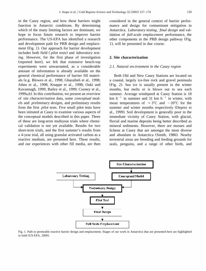
in the Casey region, and how these barriers mightfunction in Antarctic conditions. By determiningwhich of the many limiting factors are dominant, wehope to focus future research to improve barrierperformance. The US-EPA has identified a researchand development path for PRB design and emplace-
Ž .ment Fig. 1 . Our approach for barrier developmentŽ .includes both field pilot tests and laboratory test-
ing. However, for the first phase of investigationŽ .reported here , we felt that extensive bench-topexperiments were unwarranted, as a considerableamount of information is already available on thegeneral chemical performance of barrier fill materi-
Žals e.g. Blowes et al., 1998; Gharaibeh et al., 1998;Johns et al., 1998; Knappe et al., 1998; Ouki andKavannagh, 1999; Bailey et al., 1999; Cooney et al.,
.1999a,b . In this contribution, we present an overviewof site characterisation data, some conceptual mod-els and preliminary designs, and preliminary resultsfrom the first pilot tests. Five small pilot tests havebeen initiated at Casey to examine various aspects ofthe conceptual models described in this paper. Threeof these are long-term multiyear trials where chemi-cal validation is not yet available. Results for twoshort-term trials, and the first summer’s results froma 4-year trial, all using granular activated carbon as areactive medium, are presented here. These results,and our experiences with other fill media, are then
considered in the general context of barrier perfor-mance and design for contaminant mitigation inAntarctica. Laboratory testing, final design and val-idation of full-scale emplacement performance, the
Žother components in the PRB design pathway Fig..1 , will be presented in due course.
2. Site characterization
2.1. Natural enÕironment in the Casey region
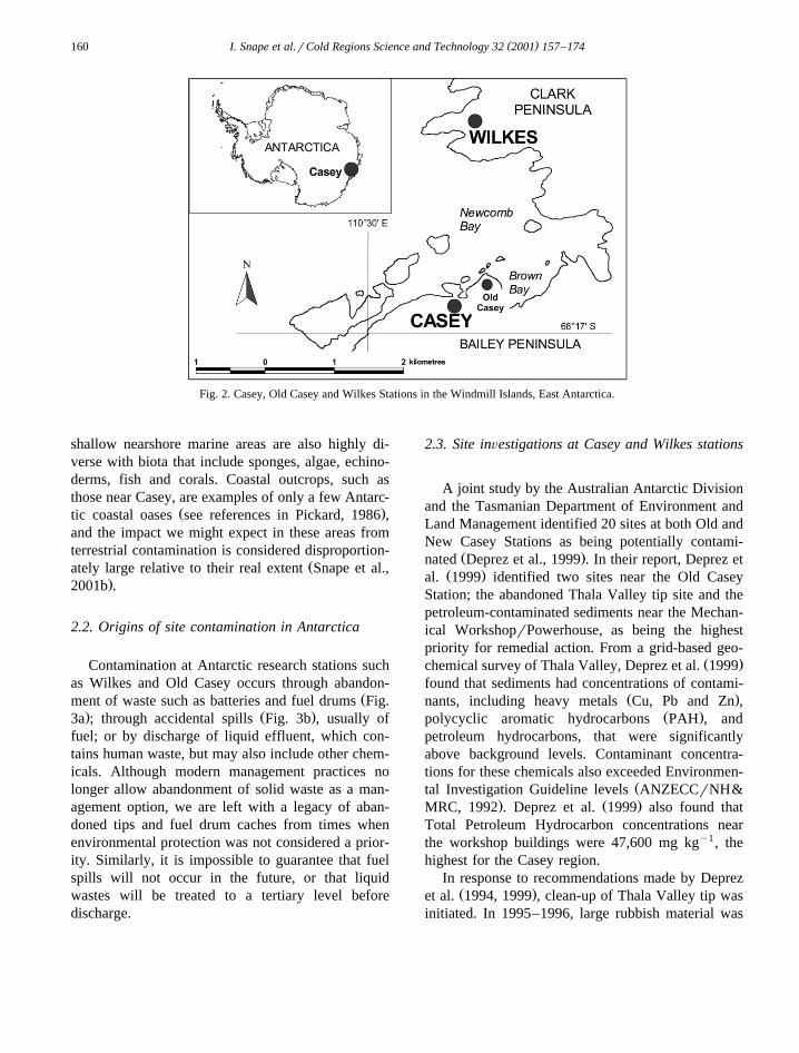
Both Old and New Casey Stations are located ona coastal, largely ice-free rock and gravel peninsulaŽ .Fig. 2 . Sea ice is usually present in the wintermonths, but melts or is blown out to sea eachsummer. Average windspeed at Casey Station is 18km hy1 in summer and 31 km hy1 in winter, withmean temperatures of ;38C and y208C for the
Žsummer and winter months respectively Deprez et.al., 1999 . Soil development is generally poor in the
immediate vicinity of Casey Station, with glacial,fluvial and marine deposits being better described asmineral sediments. However, there are mosses andlichens at Casey that are amongst the most diverse
Ž .and abundant in Antarctica Smith, 1986 . Nearbyterrestrial areas are breeding and feeding grounds forseals, penguins, and a range of other birds, and
Fig. 1. Path to permeable reactive barrier design and emplacement. Stages of our work in Antarctica that are presented here are highlightedŽ .in bold US-EPA, 2000 .
( )I. Snape et al.rCold Regions Science and Technology 32 2001 157–174160
Fig. 2. Casey, Old Casey and Wilkes Stations in the Windmill Islands, East Antarctica.
shallow nearshore marine areas are also highly di-verse with biota that include sponges, algae, echino-derms, fish and corals. Coastal outcrops, such asthose near Casey, are examples of only a few Antarc-
Ž .tic coastal oases see references in Pickard, 1986 ,and the impact we might expect in these areas fromterrestrial contamination is considered disproportion-
Žately large relative to their real extent Snape et al.,.2001b .
2.2. Origins of site contamination in Antarctica
Contamination at Antarctic research stations suchas Wilkes and Old Casey occurs through abandon-
Žment of waste such as batteries and fuel drums Fig.. Ž .3a ; through accidental spills Fig. 3b , usually of
fuel; or by discharge of liquid effluent, which con-tains human waste, but may also include other chem-icals. Although modern management practices nolonger allow abandonment of solid waste as a man-agement option, we are left with a legacy of aban-doned tips and fuel drum caches from times whenenvironmental protection was not considered a prior-ity. Similarly, it is impossible to guarantee that fuelspills will not occur in the future, or that liquidwastes will be treated to a tertiary level beforedischarge.
2.3. Site inÕestigations at Casey and Wilkes stations
A joint study by the Australian Antarctic Divisionand the Tasmanian Department of Environment andLand Management identified 20 sites at both Old andNew Casey Stations as being potentially contami-
Ž .nated Deprez et al., 1999 . In their report, Deprez etŽ .al. 1999 identified two sites near the Old Casey
Station; the abandoned Thala Valley tip site and thepetroleum-contaminated sediments near the Mechan-ical WorkshoprPowerhouse, as being the highestpriority for remedial action. From a grid-based geo-
Ž .chemical survey of Thala Valley, Deprez et al. 1999found that sediments had concentrations of contami-
Ž .nants, including heavy metals Cu, Pb and Zn ,Ž .polycyclic aromatic hydrocarbons PAH , and
petroleum hydrocarbons, that were significantlyabove background levels. Contaminant concentra-tions for these chemicals also exceeded Environmen-
Žtal Investigation Guideline levels ANZECCrNH&. Ž .MRC, 1992 . Deprez et al. 1999 also found that
Total Petroleum Hydrocarbon concentrations nearthe workshop buildings were 47,600 mg kgy1, thehighest for the Casey region.
In response to recommendations made by DeprezŽ .et al. 1994, 1999 , clean-up of Thala Valley tip was
initiated. In 1995–1996, large rubbish material was
( )I. Snape et al.rCold Regions Science and Technology 32 2001 157–174 161
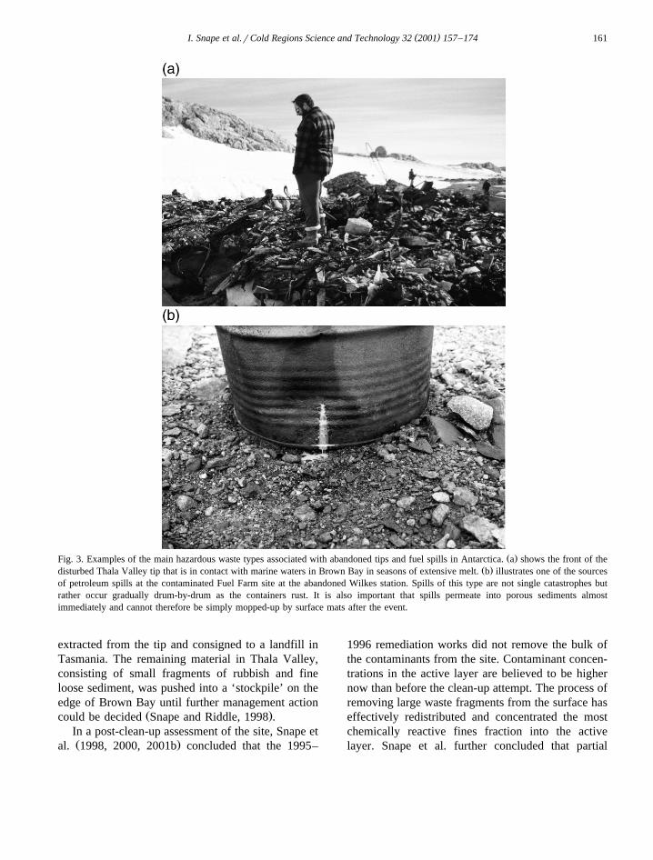
Ž .Fig. 3. Examples of the main hazardous waste types associated with abandoned tips and fuel spills in Antarctica. a shows the front of theŽ .disturbed Thala Valley tip that is in contact with marine waters in Brown Bay in seasons of extensive melt. b illustrates one of the sources
of petroleum spills at the contaminated Fuel Farm site at the abandoned Wilkes station. Spills of this type are not single catastrophes butrather occur gradually drum-by-drum as the containers rust. It is also important that spills permeate into porous sediments almostimmediately and cannot therefore be simply mopped-up by surface mats after the event.
extracted from the tip and consigned to a landfill inTasmania. The remaining material in Thala Valley,consisting of small fragments of rubbish and fineloose sediment, was pushed into a ‘stockpile’ on theedge of Brown Bay until further management action
Ž .could be decided Snape and Riddle, 1998 .In a post-clean-up assessment of the site, Snape etŽ .al. 1998, 2000, 2001b concluded that the 1995–
1996 remediation works did not remove the bulk ofthe contaminants from the site. Contaminant concen-trations in the active layer are believed to be highernow than before the clean-up attempt. The process ofremoving large waste fragments from the surface haseffectively redistributed and concentrated the mostchemically reactive fines fraction into the activelayer. Snape et al. further concluded that partial
( )I. Snape et al.rCold Regions Science and Technology 32 2001 157–174162
removal of the tip material without controlling andtreating the surface and subsurface waters that movedthrough the site would inevitably have caused agreater than ‘normal’ contaminant flux into BrownBay during the excavation operation.
An identification and assessment of sites at thenearby Wilkes Station revealed that both heavy-metal- and petroleum-contaminated waters wereflowing from the tip and fuel farm areas into the
Ž .nearby marine environment Snape et al., 1998 . Aswith the sites at Casey, two main areas and types of
Žcontaminants were identified at Wilkes: A large ;3. 320,000 m tip site, and up to 10,000 m of
petroleum-contaminated sediments at the abandonedŽ .Fuel Farm site Snape et al., 1998 . Although only
1r10 the size of the Wilkes contaminated sites,Thala Valley is highly disturbed and is consideredthe highest priority for management. It is for thisreason that our studies have concentrated on ThalaValley.
2.4. Contaminant types and concentrations
In both the Thala Valley and Wilkes tip sites,results from our work show that the heavy metalcontaminants are predominantly copper, lead, zinc,iron, cadmium, antimony and arsenic, with localisedhotspots of silver. Both water- and acid-extractableconcentrations of these metals in tip sediments wereseveral- to hundreds-of-times greater than back-
Ž .ground values Snape et al., 2001a,b . These mea-sured levels exceed Australian National Environ-mental Investigation Guideline levels by more than
Ž100-fold in some instances ANZECCrNH&MRC,.1992 . Similarly, metal concentrations in freshwater
runoff were also significantly above background val-ues and Australian National Environmental Guide-line Levels for the Protection of Aquatic EcosystemsŽ .ANZECC, 1992; Snape et al., 2001a,b .
Sediments in locations where major spills haveoccurred are greatly enriched in petroleum hydrocar-bons. In some instances, fuels and oils have been inthe ground for several years, or even decades, with
Žlittle apparent natural biodegradation Guille et al.,.1997; Snape et al., 2001a,b; cf. Gore et al., 1999 .
Detailed geochemical analysis of petroleum-con-taminated sediments at both Casey and Wilkes Sta-tions indicated that the major fuel type in the sedi-ments is largely undegraded Special Antarctic Blend
Ž .SAB diesel, with lesser amounts of lubrication oilŽ .Snape et al., 2001a,b .
2.5. Contaminant dispersal processes and site-specific conditions
By considering contaminant dispersal in the Caseyregion in a catchment context, it has been possible tosemi-quantitatively define the primary contaminanttransfer mechanisms and pathways for various con-taminants at different sites. For petroleum contami-
Ž .nants, Cole et al. 2000 concluded that pervasivesubsurface transport was the main transfer mecha-nism at the Old Casey WorkshoprPowerhouse site.Surface runoff tended to dominate with the initialmelt pulse, when the ground was still largely frozen,but for most of the 2–3 months of summer seasonthere was little or no surface runoff, and subsurfaceadvection through highly permeable sediments was amore important contaminant dispersal mechanism.Petroleum contaminants are visibly leaching into themarine environment, and at a rate that is greater thanthe rate of natural breakdown, which are importantobservations for the environmental management of
Ž .the region Snape et al., 2001a,b .For heavy metal contaminants, our studies of
water–contaminant–sediment interaction at ThalaValley and Wilkes tips show that lateral dispersal ofwater-borne contaminants occurs by both surface and
Žsubsurface runoff Snape et al., 2001a,b; cf. Shep-.pard et al., 2000 . Surface runoff through the tip
occurs in ephemeral channels that develop in ice andsediments, usually either at the ice–sediment or ac-tive-layer–permafrost interfaces. Lateral channel mi-gration is common. Contaminated subsurface watermovement occurs through pervasive dispersal and
Žadvection, but also via small channels mm- to dm-.scales within the sediment profile, usually at the
base of the active layer. Metal concentrations in bothsurface and subsurface waters typically vary fromless than mg ly1 levels prior to interaction with thetip contaminants, to mg ly1 levels as waters passthrough the tip, an increase of more than 1000-fold.
Recognising that subsurface transport and particu-late entrainment are key aspects of the dispersalprocess has important implications for catchmentmanagement. Although the main stream course in
( )I. Snape et al.rCold Regions Science and Technology 32 2001 157–174 163
Thala Valley can be diverted away from the tipduring excavation and removal, small streams andsubsurface water derived from melting snow over-burden cannot be effectively diverted by engineeringmeans. Installing an impermeable barrier without apump and treat system is not practicable becauseponded water would hamper the extraction process.Similarly, in the Old Casey Station WorkshoprPowerhouse catchment, an impermeable barrierwould also be unsuitable because of problems withponding and freezing. Sorbant mats placed on theground surface would be a largely ineffective meansby which to limit dispersal in this catchment, be-cause subsurface transport is the dominant dispersalmechanism for most of the year. It is for thesereasons that we are testing the use of PRBs for theremediation of the Thala Valley tip and WorkshoprPowerhouse sites.
3. Conceptual models
3.1. Methodology
Permeable barrier systems are a relatively newmethodology that are being employed in site remedi-ation scenarios that require treatment of contami-nated surface and subsurface waters. In a generalsense permeable reactive barriers are:
An emplacement of materials designed to inter-cept a contaminant plume, provide a flow paththrough the system, and to transform the contami-nants into environmentally acceptable forms, or tootherwise remove the contaminants to attain theremediation concentration goals down gradient of
Žthe barrier modified from Powell and Powell,.1998 .
The methodology is usually passive, relying onhydraulic gradients to transport the contaminatedwater through the treatment process, with retentionor remediation occurring as the plume moves throughthe barrier. The underlying principle is that porous
Ž .media will interact with the contaminant s throughphysical, chemical and biological processes that rangefrom simple filtration of contaminants adsorbed tosoil particles, through to more complex chemicalŽ .e.g. oxidationrreduction, absorption, complexation
and biological reactions that result in the destructionŽ .or precipitation of the contaminant s from the flow-
Ž .ing water e.g. US-EPA, 1998, 1999 .
3.2. Rationale for application in Antarctica
Permeable barriers are being proposed and testedas a possible remediation methodology for use in theAntarctic because they:
Ø are easy to install and have few infrastructurerequirements;
Ø require minimal monitoring and maintenance;Ø are passive systems that do not require energy
input;Ø are suitable for both surface and subsurface
flow regimes;Ø will function well in varied temperature and
water flow conditions.
3.3. Emplacement and construction techniques
The constructionrinstallation of permeable barri-ers in the Antarctic is similar in many ways to thoseinstalled in temperate climates throughout the world.However, cold temperatures, seasonally and diur-nally frozen ground and the requirement to removeall barrier materials upon completion of the remedia-tion effort requires modifications to standard prac-tices. The requirement in Antarctica to remove andtransport barriers back to country of origin for ulti-mate disposal, coupled with the need to minimiselabour on-site for installation of the systems, led usto focus our initial efforts on modular systems. Fab-ricating the barrier system as a portable single unit oras a series of modules that are installed and con-nected on-site will reduce the time spent in gettingthe system operational. This will also simplify theremoval process after remediation, providing mod-ules are sufficiently robust to withstand extraction.
In most cases, permeable barriers will be requiredto treat contaminated subsurface water. This willrequire trench excavation for installation. In the areaswe investigated in the Casey area, the depth topermafrost is usually less than 1.5 m; therefore, thetrenches only need to be very shallow in comparison
Žto most sites in temperate regions e.g. US-EPA,
( )I. Snape et al.rCold Regions Science and Technology 32 2001 157–174164
.1998 . Experience to date indicates that excavationand installation will be best early in the summerseason before extensive melting occurs. Althoughtrench excavation of frozen ground at this time is
Žproblematic e.g. Sellmann, 1989; Sellmann and.Brockett, 1992; Snape and Riddle, 1998 , the prepa-
ration of the trench and barrier construction is easierwhen sediments are still frozen. Moreover, contami-nants remain trapped in frozen water and are thusless likely to be disturbed and dispersed by barrierinstallation.
4. Preliminary designs
We are currently developing three types of perme-able barriers for use in the Casey region. All aretemporary systems that we envisage will have gen-eral applicability as part of remediation schemes inAntarctica and possibly other Polar or High Alpineareas.
The first type of system is designed to be installeddown-gradient from sites requiring excavation andremoval of rubbish and soils where short-term con-trol of heavy metal and petroleum-hydrocarbon con-
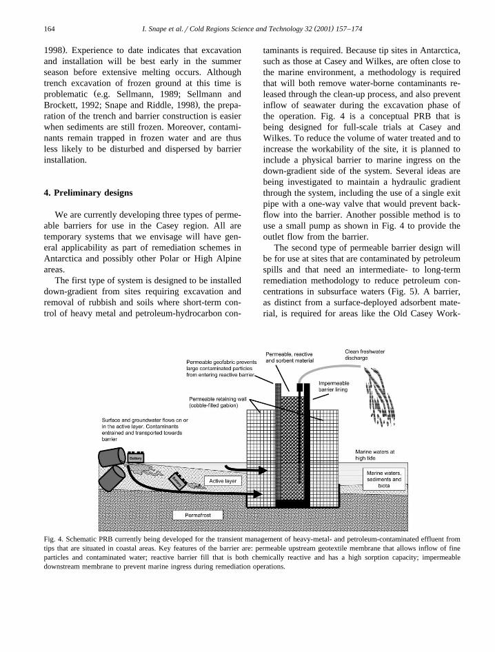
taminants is required. Because tip sites in Antarctica,such as those at Casey and Wilkes, are often close tothe marine environment, a methodology is requiredthat will both remove water-borne contaminants re-leased through the clean-up process, and also preventinflow of seawater during the excavation phase ofthe operation. Fig. 4 is a conceptual PRB that isbeing designed for full-scale trials at Casey andWilkes. To reduce the volume of water treated and toincrease the workability of the site, it is planned toinclude a physical barrier to marine ingress on thedown-gradient side of the system. Several ideas arebeing investigated to maintain a hydraulic gradientthrough the system, including the use of a single exitpipe with a one-way valve that would prevent back-flow into the barrier. Another possible method is touse a small pump as shown in Fig. 4 to provide theoutlet flow from the barrier.
The second type of permeable barrier design willbe for use at sites that are contaminated by petroleumspills and that need an intermediate- to long-termremediation methodology to reduce petroleum con-
Ž .centrations in subsurface waters Fig. 5 . A barrier,as distinct from a surface-deployed adsorbent mate-rial, is required for areas like the Old Casey Work-
Fig. 4. Schematic PRB currently being developed for the transient management of heavy-metal- and petroleum-contaminated effluent fromtips that are situated in coastal areas. Key features of the barrier are: permeable upstream geotextile membrane that allows inflow of fineparticles and contaminated water; reactive barrier fill that is both chemically reactive and has a high sorption capacity; impermeabledownstream membrane to prevent marine ingress during remediation operations.
( )I. Snape et al.rCold Regions Science and Technology 32 2001 157–174 165
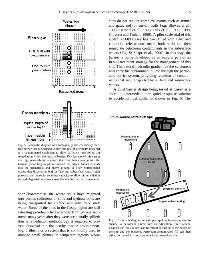
Fig. 5. Schematic diagram of a biologically and chemically reac-tive barrier that is designed to slow the rate of petroleum dispersalin a contaminated catchment to allow sufficient time for in-situremediation within the reactive barrier. Key features of this designare: high permeability to ensure that flow lines converge into thebarriers preventing migration around the edges; barrier extendsinto the permafrost and above ground to filter contaminatedwaters that disperse as both surface and subsurface runoff; highporosity and microbial retaining capacity to allow bioremediation
Ž .through degradation enhancement bioreactive barrier component .
shoprPowerhouse site where spills have migratedinto porous sediments or soils and hydrocarbons arebeing transported by surface and subsurface meltwater. Some of the sites in the Casey region are stillreleasing petroleum hydrocarbons from porous sedi-ments many years after they were accidentally spilled;thus a remediation methodology is required to pre-vent dispersal into the nearby marine environment.Fig. 5 illustrates a system that is commonly used tomanage small plumes in temperate regions where
sites do not require complex layouts such as funnelŽand gates andror cut-off walls e.g. Blowes et al.,
1998; Herbert et al., 1998; Puls et al., 1998, 1999;.Cravotta and Trahan, 1999 . A pilot-scale trial of this
system at Old Casey has been filled with GAC andcontrolled release nutrients to both retain and thenremediate petroleum contaminants in the subsurface
Ž .waters Fig. 5; Snape et al., 2000 . In this way, thebarrier is being developed as an integral part of anin-situ treatment strategy for the management of thissite. The natural hydraulic gradient of the catchmentwill carry the contaminant plume through the perme-able barrier system, providing retention of contami-nants that are transported by surface and subsurfacewaters.
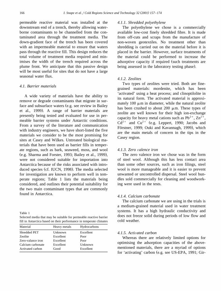
A third barrier design being tested at Casey as ashort- to intermediate-term quick response solutionto accidental fuel spills, is shown in Fig. 6. The
Fig. 6. Schematic diagram of a simple rapid deployment system tochannel a petroleum plume into an adsorption filter system.Channel and fill volumes can be varied according to the nature ofthe site and the incident. Petroleum-contaminated fill can theneither be treated in situ or removed and treated ex situ.
( )I. Snape et al.rCold Regions Science and Technology 32 2001 157–174166
permeable reactive material was installed at thedownstream end of a trench, thereby allowing water-borne contaminants to be channelled from the con-taminated area through the treatment media. Thedown-gradient face of the trench has been coveredwith an impermeable material to ensure that waterspass through the reactive fill. This design reduces thetotal volume of treatment media required and min-imises the width of the trench required across theplume front. We anticipate that this passive designwill be most useful for sites that do not have a largeseasonal water flux.
4.1. Barrier materials
A wide variety of materials have the ability toremove or degrade contaminants that migrate in sur-
Žface and subsurface waters e.g. see review in Bailey.et al., 1999 . A range of barrier materials are
presently being tested and evaluated for use in per-meable barrier systems under Antarctic conditions.From a survey of the literature and communicationwith industry engineers, we have short-listed the fivematerials we consider to be the most promising forsites at Casey and Wilkes. Untreated biological ma-terials that have been used as barrier fills in temper-ate regions, such as bark, seaweed, moss, and woolŽ .e.g. Sharma and Forster, 1993; Bailey et al., 1999 ,were not considered suitable for importation intoAntarctica because of the risks associated with intro-
Ž .duced species cf. IUCN, 1998 . The media selectedfor investigation are known to perform well in tem-perate regions; Table 1 lists the materials beingconsidered, and outlines their potential suitability forthe two main contaminant types that are commonlyfound in Antarctica.
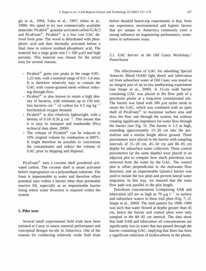
Table 1Selected media that may be suitable for permeable reactive barrierfill in Antarctica based on their performance in temperate climates
Material Heavy metals Hydrocarbons
Shredded PET Unknown ExcellentZeolite Excellent PoorZero-valance iron Excellent PoorCalcium carbonate Excellent UnknownActivated carbon Good Excellent
4.1.1. Shredded polyethyleneThe polyethylene we chose is a commercially
available low-cost finely shredded fibre. It is madefrom off-cuts and scraps from the manufacture ofnon-woven geotextiles. No treatment other thanshredding is carried out on the material before it isplaced in the barrier. However, surface treatments ofthe material could be performed to increase the
Žadsorptive capacity if required such treatments are.being assessed in the laboratory testing phase .
4.1.2. ZeolitesTwo types of zeolites were tried. Both are fine-
grained materials: mordenite, which has been‘activated’ using a heat process; and clinoptilolite inits natural form. The activated material is approxi-mately 100 mm in diameter, while the natural zeolitehas been crushed to about 200 mm. These types ofzeolite are well known for their high ion-exchangecapacity for heavy metal cations such as Pb2q, Zn2q,
2q 2q ŽCd and Cu e.g. Leppert, 1990; Jacobs and.Forstner, 1999; Ouki and Kavannagh, 1999 , which¨
are the main metals of concern in the tips in theCasey region.
4.1.3. Zero Õalence ironThe zero valence iron we chose was in the form
of steel wool. Although this has less contact areathan some other sources, such as iron filings, steelwool is more manageable and it is easier to preventunwanted or uncontrolled dispersal. Steel wool bun-dles sold commercially for cleaning and woodwork-ing were used in the tests.
4.1.4. Calcium carbonateThe calcium carbonate we are using in the trials is
a medium-grained material used in water treatmentsystems. It has a high hydraulic conductivity anddoes not freeze solid during periods of low flow andcold weather.
4.1.5. ActiÕated carbonWhereas there are relatively limited options for
optimising the adsorption capacities of the above-mentioned materials, there are a myriad of options
Žfor ‘activating’ carbon e.g. see US-EPA, 1991; Gir-
( )I. Snape et al.rCold Regions Science and Technology 32 2001 157–174 167
gis et al., 1994; Toles et al., 1997; Johns et al.,.1998 . We opted to try two commercially available
w Ž .materials: Picabiol granular activated carbon GACand PicaFoamw. Picabiolw is a low cost GAC de-rived from pine. The wood is dehydrated with phos-phoric acid and then thermally activated before afinal rinse to remove residual phosphoric acid. The
Ž .material has a large grain size )500 mm and highporosity. This material was chosen for the initialtests for several reasons:
Ø Picabiolw grain size peaks in the range 0.85–1.25 mm, with a nominal range of 0.5–1.4 mm.It is therefore relatively easy to contain theGAC with coarse-grained mesh without reduc-ing through-flow.
Ø Picabiolw is also known to retain a high den-sity of bacteria, with estimates up to 150 mil-lion bacteria cmy3 of carbon for 0.5 mg kgy1
biochemical oxygen demand.Ø Picabiolw is also relatively lightweight, with a
density of 0.18–0.26 g cmy3. This means thatŽit is easy to transport and manhandle Pica
.technical data sheet, 2000 .Ø The volume of Picabiolw can be reduced to
10% original volume by combustion at 6008C.It might therefore be possible to concentratethe contaminants and reduce the volume ofGAC prior to shipping and disposal.
PicaFoamw uses a coconut shell powdered acti-vated carbon. The coconut shell is steam activatedbefore impregnation on a polyurethane substrate. Thefoam is impermeable to water and therefore offerspotential uses within a barrier other than permeablereactive fill, especially as an impermeable barrierlining where water diversion is required within thesystem.
5. Pilot tests
Several small experimental field trials have beeninitiated at Casey to assess material performance andconceptual designs on-site in Antarctica. One of thereasons for conducting relatively crude field trials
before detailed bench-top experiments is that, fromour experience, environmental and logistic factorsthat are unique to Antarctica commonly exert astrong influence on engineering performance, some-times in unforeseen ways.
5.1. GAC barrier at the Old Casey WorkshoprPowerhouse
The effectiveness of GAC for adsorbing SpecialŽ .Antarctic Blend SAB light diesel and lubrication
oil from subsurface water at Old Casey was tested asan integral part of an in-situ landfarming experimentŽ .see Snape et al., 2000 . A 15-cm wide barriercontaining GAC was placed in the flow path of apetroleum plume at a long-term contaminated site.The barrier was lined with 500 mm nylon mesh toretain the GAC, which was combined with an openshell of PicaFoamw to maximise surface area andslow the flow rate through the system, but withoutcreating significant impedance for water flow through
Ž .the barrier see Fig. 5 . The barrier is 1.5 m high,extending approximately 15–20 cm into the per-mafrost and a similar height above ground. Threepiezometers were placed in the barrier with samplingintervals of 15–20 cm, 45–50 cm and 80–85 cmdepths for subsurface water collection. Three control
Ž .piezometers at the same depths were placed in anadjacent plot to compare how much petroleum wasremoved from the water by the GAC. The controlplot is offset perpendicular to the meltwater flow
Ž .direction, and an impermeable plastic barrier wasused to isolate the two plots and prevent lateral watermigration. In this way, we ensured that the mainflow path was parallel to the plot length.
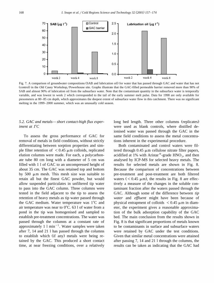
ŽPetroleum concentrations comprising SAB and. y1lubrication oil are as high as 70 mg l in surface
Žand subsurface waters in these trial plots Fig. 7; cf..Snape et al., 2000 . The melt pattern for 1998–1999
was such that water flowed at depths greater than 45cm, hence the barrier and control plots were onlysampled in the 80–85 cm interval. The data showthat both SAB and lubrication oil concentrations aresignificantly less in water that has passed through thebarrier containing GAC, implying that there has beena significant reduction of hydrocarbons in the plume.
( )I. Snape et al.rCold Regions Science and Technology 32 2001 157–174168
Ž .Fig. 7. A comparison of groundwater compositions SAB and lubrication oil for water that has passed through GAC and water that has notŽ .control in the Old Casey WorkshoprPowerhouse site. Graphs illustrate that the GAC-filled permeable barrier removed more than 90% ofSAB and almost 90% of lubrication oil from the subsurface water. Note that the contaminant quantity in the subsurface water is temporallyvariable, and was lowest in week 2 which corresponded to the tail of the early summer melt pulse. Data for 1998 are only available forpiesometers at 80–85 cm depth, which approximates the deepest extent of subsurface water flow in this catchment. There was no significantmelting in the 1999–2000 summer, which was an unusually cold season.
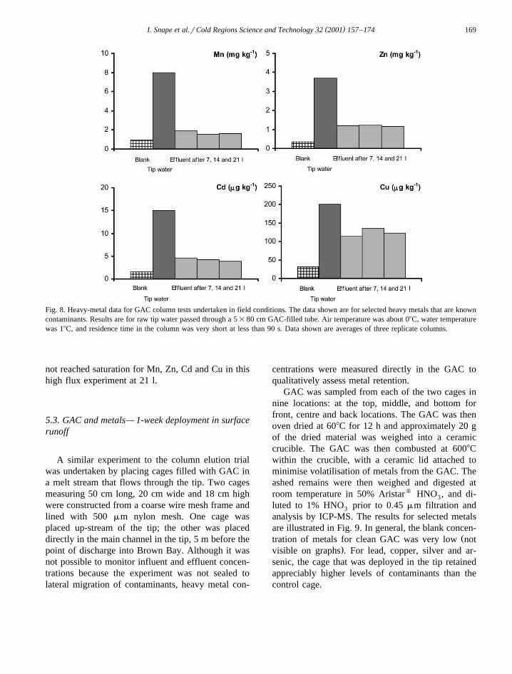
5.2. GAC and metals— short contact-high flux exper-iment at 18C
To assess the gross performance of GAC forremoval of metals in field conditions, without strictlydifferentiating between sorption properties and sim-ple filter retention of -0.45 mm colloids, replicatedelution columns were made. For each, a polycarbon-ate tube 80 cm long with a diameter of 5 cm wasfilled with 1 l of GAC to an uncompressed height ofabout 35 cm. The GAC was retained top and bottomby 500 mm mesh. This mesh size was suitable toretain all but the finest GAC powder, but wouldallow suspended particulates in unfiltered tip waterto pass into the GAC column. Three columns weretested in the field adjacent to the tip to assess theretention of heavy metals as tip water passed throughthe GAC medium. Water temperature was 18C andair temperature was near to 08C. 63 l of water from apond in the tip was homogenised and sampled toestablish pre-treatment concentrations. The water waspassed through the columns at a constant rate ofapproximately 1 l miny1. Water samples were takenafter 7, 14 and 21 l has passed through the columns
Ž .to establish which if any metals were being re-tained by the GAC. This produced a short contacttime, at near freezing conditions, over a relatively
Ž .long bed length. Three other columns replicateswere used as blank controls, where distilled de-ionised water was passed through the GAC in thesame field conditions to assess the metal concentra-tions inherent in the experimental procedure.
Both contaminated and control waters were fil-tered through 0.45 mm cellulose nitrate filter papers,acidified at 1% with Aristarw-grade HNO , and then3
analysed by ICP-MS for selected heavy metals. Theresults for selected metals are shown in Fig. 8.Because the comparison of concentrations betweenpre-treatment and post-treatment are both filtered
Ž .waters -0.45 mm , the results in Fig. 8 are effec-tively a measure of the changes in the soluble con-taminant fraction after the waters passed through theGAC. Although some of the difference between tipwater and effluent might have been because ofphysical entrapment of colloids -0.45 mm in diam-eter, the experiment gives a reasonable approxima-tion of the bulk adsorption capability of the GACbed. The main conclusion from the results shown inFig. 8 is that significant proportions of metals knownto be contaminants in surface and subsurface waterswere retained by GAC under the test conditions.Given that similar metal concentrations were attainedafter passing 7, 14 and 21 l through the columns, theresults can be taken as indicating that the GAC had
( )I. Snape et al.rCold Regions Science and Technology 32 2001 157–174 169
Fig. 8. Heavy-metal data for GAC column tests undertaken in field conditions. The data shown are for selected heavy metals that are knowncontaminants. Results are for raw tip water passed through a 5=80 cm GAC-filled tube. Air temperature was about 08C, water temperaturewas 18C, and residence time in the column was very short at less than 90 s. Data shown are averages of three replicate columns.
not reached saturation for Mn, Zn, Cd and Cu in thishigh flux experiment at 21 l.
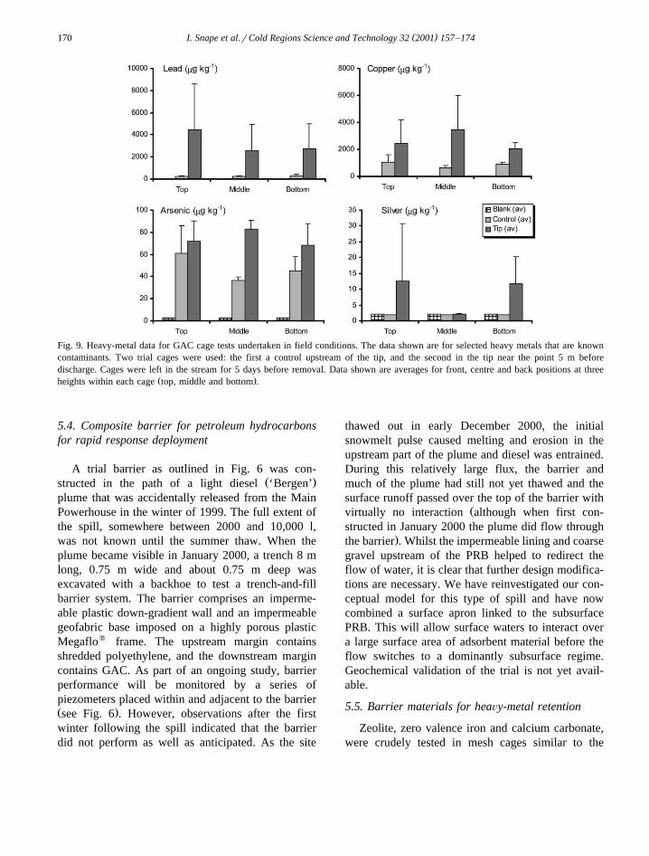
5.3. GAC and metals— 1-week deployment in surfacerunoff
A similar experiment to the column elution trialwas undertaken by placing cages filled with GAC ina melt stream that flows through the tip. Two cagesmeasuring 50 cm long, 20 cm wide and 18 cm highwere constructed from a coarse wire mesh frame andlined with 500 mm nylon mesh. One cage wasplaced up-stream of the tip; the other was placeddirectly in the main channel in the tip, 5 m before thepoint of discharge into Brown Bay. Although it wasnot possible to monitor influent and effluent concen-trations because the experiment was not sealed tolateral migration of contaminants, heavy metal con-
centrations were measured directly in the GAC toqualitatively assess metal retention.
GAC was sampled from each of the two cages innine locations: at the top, middle, and bottom forfront, centre and back locations. The GAC was thenoven dried at 608C for 12 h and approximately 20 gof the dried material was weighed into a ceramiccrucible. The GAC was then combusted at 6008Cwithin the crucible, with a ceramic lid attached tominimise volatilisation of metals from the GAC. Theashed remains were then weighed and digested atroom temperature in 50% Aristarw HNO , and di-3
luted to 1% HNO prior to 0.45 mm filtration and3
analysis by ICP-MS. The results for selected metalsare illustrated in Fig. 9. In general, the blank concen-
Žtration of metals for clean GAC was very low not.visible on graphs . For lead, copper, silver and ar-
senic, the cage that was deployed in the tip retainedappreciably higher levels of contaminants than thecontrol cage.
( )I. Snape et al.rCold Regions Science and Technology 32 2001 157–174170
Fig. 9. Heavy-metal data for GAC cage tests undertaken in field conditions. The data shown are for selected heavy metals that are knowncontaminants. Two trial cages were used: the first a control upstream of the tip, and the second in the tip near the point 5 m beforedischarge. Cages were left in the stream for 5 days before removal. Data shown are averages for front, centre and back positions at three
Ž .heights within each cage top, middle and bottom .
5.4. Composite barrier for petroleum hydrocarbonsfor rapid response deployment
A trial barrier as outlined in Fig. 6 was con-Ž .structed in the path of a light diesel ‘Bergen’
plume that was accidentally released from the MainPowerhouse in the winter of 1999. The full extent ofthe spill, somewhere between 2000 and 10,000 l,was not known until the summer thaw. When theplume became visible in January 2000, a trench 8 mlong, 0.75 m wide and about 0.75 m deep wasexcavated with a backhoe to test a trench-and-fillbarrier system. The barrier comprises an imperme-able plastic down-gradient wall and an impermeablegeofabric base imposed on a highly porous plasticMegaflow frame. The upstream margin containsshredded polyethylene, and the downstream margincontains GAC. As part of an ongoing study, barrierperformance will be monitored by a series ofpiezometers placed within and adjacent to the barrierŽ .see Fig. 6 . However, observations after the firstwinter following the spill indicated that the barrierdid not perform as well as anticipated. As the site
thawed out in early December 2000, the initialsnowmelt pulse caused melting and erosion in theupstream part of the plume and diesel was entrained.During this relatively large flux, the barrier andmuch of the plume had still not yet thawed and thesurface runoff passed over the top of the barrier with
Žvirtually no interaction although when first con-structed in January 2000 the plume did flow through
.the barrier . Whilst the impermeable lining and coarsegravel upstream of the PRB helped to redirect theflow of water, it is clear that further design modifica-tions are necessary. We have reinvestigated our con-ceptual model for this type of spill and have nowcombined a surface apron linked to the subsurfacePRB. This will allow surface waters to interact overa large surface area of adsorbent material before theflow switches to a dominantly subsurface regime.Geochemical validation of the trial is not yet avail-able.
5.5. Barrier materials for heaÕy-metal retention
Zeolite, zero valence iron and calcium carbonate,were crudely tested in mesh cages similar to the
( )I. Snape et al.rCold Regions Science and Technology 32 2001 157–174 171
GAC cages described in Section 5.3. The cages wereplaced in the tip stream for 1 year over the winter of2000. Laboratory results from other work predictedhigh adsorption capacities for zeolites with, for ex-
Ž .ample, trials on fine-grained ;150 mm zeolitesŽyielding of the order 150 g Pbrkg zeolites e.g.
.Leppert, 1990; see also Bailey et al., 1999 , but wefound that the use of fine-grained zeolites in Antarc-tica was severely hampered by the small grain-sizeand associated low porosity. Both zeolite types andthe CaCO were difficult to contain and prevent3
entrainment, and hence dispersal, by subsurface wa-ters. Retention in a sufficiently fine mesh to preventthis effectively led to clogging at the barrier–sedi-ment interface, and prevented particulates and thecontaminant plume from entering the barrier. A moreserious problem concerns the response to diurnalfreeze-thaw. We found in trials using fine-grainedmaterials in the trench experiments, that water wouldfreeze in the fine materials rather than drain freely,and that the barrier would not remain as permeable
Žas the surrounding coarse-grained and hence free-.draining contaminated sediments. For these reasons,
we are now considering coarse-grained, aggregated,and impregnated zeolite for future testing. By com-parison, zero valence iron, shredded PET, and GACwere all relatively straightforward to emplace andrecover from frozen ground if properly contained ina robust shell or cage. Also, because they arecoarse-grained andror highly porous, we predictfrom preliminary observations that adequate though-flow will be possible for the duration of a remedia-tion operation. Chemical results for these multiyearfield trials, and a comparison with low temperaturecolumn tests are not yet available.
6. Discussion
Our results indicate that PRBs could be importantcomponents within an integrated management strat-egy that would typically involve both bulk removaland in-situ or on-site remediation. However, ourlimited experiences to date indicate that many off-the-shelf applications developed for temperate re-gions are either inappropriate or will need modifica-tion if they are to be effective in Antarctica.
Geochemical validation of a simple permeablereactive barrier of Picabiolw GAC showed excellentpetroleum hydrocarbon retention during subsurfacerunoff at the Old Casey WorkshoprPowerhouse site.If long-term monitoring of the experiment supportsthe preliminary results presented here, a full-scalebarrier will be considered for installation on site atOld Casey prior to a catchment-scale landfarmingtrial. The deployment of such a barrier would servetwo main functions: primarily the barrier would slowthe down-catchment transport of petroleum to a ratethat would allow enhanced bioremediation to be
Žeffective at low temperatures bioremediation ratesare slower than commonly observed in temperate
.regions; Snape et al., 2000 . Also, by adding con-trolled-release nutrients directly into the barrier fill,the barrier would also form a focal bioreactive zonein the catchment where petroleum hydrocarbonscould be concentrated and treated. In this narrowzone, amendments other than simple nutrientŽ ."water addition might also be economically vi-able. In particular, oxygenation and active heatingmight be possible in the small volume of the barrier,whereas such treatments are not viable for large
Ž .volumes see Snape et al., 2000; Morris et al., 2000 .Although the quality of water discharged during
remediation works in the Thala Valley tip site cannotbe predicted yet, compared with the clean-up opera-tion in 1995–1996, a PRB of the type shown in Fig.4 would significantly reduce the short-term dispersalof metals such as lead and zinc. However, compre-hensive assessment of the long-term performance ofPRBs in Antarctica is essential because removal andremediation operations for most large contaminatedsites will, by logistic necessity, take place over sev-
Ž .eral seasons e.g. Snape et al., 1998 . It is encourag-ing though that one of our multiyear experimentsinvolving a GAC barrier at the Old Casey Work-shoprPowerhouse catchment appears to have hadlittle effect on the hydrology of the catchment for thethree summer seasons that it has been installed.
Finally, in conjunction with the field trials thatform the basis of this contribution, the behaviour ofbarrier materials is presently being investigated inthe laboratory at both near y08C and 208C to deter-mine differences in physico-chemical processes atthe two temperatures. In our laboratory tests aspectsof barrier design such as reaction rates at low tem-
( )I. Snape et al.rCold Regions Science and Technology 32 2001 157–174172
peratures, prediction of contaminant breakthroughcurves, bed loading, porosity reduction, and effluentwater quality are being quantified. These factors willinfluence the bed length required to achieve thenecessary reduction in contaminants in water leavingthe barrier, and therefore the dimensions of theinstalled system.
7. Conclusions
Preliminary results reported here provide a posi-tive indication that PRBs will contribute significantlyto the transient management of contaminated surfaceand subsurface waters in Antarctica. PRBs are viewedas an ideal remediation methodology for use inAntarctica since they are passive, simple to install,require little to no maintenance and should be able tocope well with the changing flow regimes andweather conditions that occur during the summermonths. By considering contaminant sources anddispersal mechanisms and pathways in the context ofenvironmental conditions found in coastal cold re-gions such as Casey, we have provided a rationaleand outline of the methodology for the deploymentof PRBs in Antarctica. This has led us to proposethree generic barrier designs: a barrier that might besuitable for tip remediation in coastal areas, a quickresponse trench-and-fill system for petroleum spills,and a PRB that can be integrated with bioremedia-tion as part of a landfarming strategy.
Our experiences with field trials indicate thatfine-grained reactive materials, although commonlyemployed in temperate regions because of their highadsorption and cation exchange capacity, are unsuit-able for deployment in Antarctica because they aredifficult to manage and do not retain high permeabil-ity flow-through characteristics in seasonally or diur-nally frozen ground.
Heavy metals and petroleum hydrocarbons havebeen identified as two important contaminant suitesthat require site management if environmental im-pacts are to be reduced at Casey, Wilkes and possi-bly other Antarctic stations. Preliminary results usingPicabiolw GAC indicate that excellent adsorption
Žwas obtained for the petroleum products Special.Antarctic Blend light diesel and lubrication oil that
are commonly used and subsequently spilled duringAntarctic station operations. Picabiolw GAC wasalso an effective adsorbent for selected heavy metals,with good retention for metals such as lead, copperand zinc which are the main contaminants associatedwith the abandoned tips in Antarctica. Nevertheless,further research will be needed to develop the modu-lar concept for barrier fabrication to enable rapiddeployment in remote areas. It is hoped that suchsystems will also meet the need to ensure efficientrecovery from frozen ground at the end of the treat-ment phase.
Our focus now is to refine sequential reactive fillassociations to utilise different physicalrchemicalproperties of materials to ensure retention of mix-tures of organic and inorganic contaminants. It isalso desirable to optimise fill volumes based on athorough laboratory quantification of breakthroughcurves and reaction and adsorption rates at tempera-tures near to 08C. Nevertheless, final validation ofour permeable reactive barriers will only be com-plete once contaminant discharge demonstrably meetstarget requirements in the full-scale removal andremediation operations that are being considered forcontaminated sites in this Antarctic region.
Acknowledgements
We gratefully acknowledge the financial and lo-gistic support of the Australian National Antarctic
Ž .Research Expeditions ANARE and the practicalhelp of expeditioners at Casey, especially NadiaBabicka. Andy Revill at CSIRO, Hobart, analysedgroundwaters for petroleum hydrocarbons. Beck
Ž .Scouller AAD undertook the sample preparation ofthe GAC. The research reported in this paper wasundertaken through ASAC grants 1163 and 1089.Support by the Trans-Antarctic Association is alsogratefully acknowledged. The ideas presented in thispaper have benefited from discussions with MartinCallinan, Damian Gore, Geoff Stevens, Martin Rid-dle, John Aulich and Jibba Nixon. Scott Stark.Damian Gore, Mike Connor, John Poland and ananonymous referee are thanked for reviewing andsignificantly improving the final version of themanuscript.
( )I. Snape et al.rCold Regions Science and Technology 32 2001 157–174 173
References
ANZECC, 1992. Australian Water Quality Guidelines for Freshand Marine Waters. Australian and New Zealand Environmentand Conservation Council, 69 pp.
ANZECCrNH&MRC, 1992. Australian and New Zealand Guide-lines for the Assessment and Management of ContaminatedSites. Australian and New Zealand Environment and Con-servation CouncilrNational Health and Medical ResearchCouncil.
Bailey, S.E., Olin, T.J., Bricka, R.M., Adrian, D.D., 1999. Areview of potentially low-cost sorbents for heavy metals.
Ž .Water Research 33 11 , 2469–2479.Blowes, D.W., Ptacek, C.J., Benner, S.G., McRae, C.W.T., 1998.
Treatment of dissolved metals using permeable reactive barri-ers. Groundwater Quality: Remediation and Protection. IAHS,Tubingen, pp. 483–490.
Cole, C.M., Snape, I., Gore, D.B., Revill, A.T., Riddle, M.J.,2000. Contaminants in the Antarctic Environment III: Chemi-cal and physical processes that influence contaminants in cold
Ž .regions. In: Hughson, T., Ruckstuhl, C. Eds. , ISCORD 2000,Hobart, Tasmania, pp. 128–131.
Cooney, E.L., Booker, N.A., Shallcross, D.C., Stevens, G.W.,1999a. Ammonia removal from wastewaters using naturalAustralian zeolite. I. Characterization of the zeolite. Separation
Ž .Science and Technology 34 12 , 2307–2327.Cooney, E.L., Booker, N.A., Shallcross, D.C., Stevens, G.W.,
1999b. Ammonia removal from wastewaters using naturalAustralian zeolite: II. Pilot-scale study using continuous packed
Ž .column process. Separation Science and Technology 34 14 ,20 pp.
Cravotta III, C.A., Trahan, M.K., 1999. Limestone drains toincrease pH and remove dissolved metals from acidic minedrainage. Applied Geochemistry 14, 581–606.
Deprez, P.P., Arens, M., Locher, H., 1994. Identification andPreliminary Assessment of Contaminated Sites in the Aus-tralian Antarctic Territory: 1. Casey Station, AustralianAntarctic Division.
Deprez, P.P., Arens, M., Locher, H., 1999. Identification andassessment of contaminated sites at Casey station, Wilkes
Ž .Land, Antarctica. Polar Record 35 195 , 299–316.Gharaibeh, S.H., Moore, S.V., Buck, A., 1998. Effluent treatment
of industrial wastewater using processed solide residue ofOlive Mill products and commercial activated carbon. Journalof Chemical Technology and Biotechnology 71, 291–298.
Girgis, B.S., Khalil, L.B., Tawfik, T.A.M., 1994. Activated car-bon from sugarcane bagasse by carbonisation in the presenceof inorganic acids. Journal of Chemical Technology andBiotechnology 61, 87–92.
Gore, D.B., Guille, D., Revill, A., 1999. Long-term fate ofpetroleum contaminants at a helipad, Bunger Hills, East
Ž .Antarctica. Antarctic Science 11 4 , 427–429.Guille, D., Revill, A., Bowman, J., 1997. Long-Term Fate
of Petroleum Contaminations at Casey Station, Antarctica,Hobart.
Herbert Jr., R.B., Benner, S.G., Blowes, D.W., 1998. Reactivebarrier treatment of groundwater contaminated by acid mine
drainage: sulphur accumulation and sulphide formation.Groundwater Quality: Remediation and Protection. IAHS,Tubingen, Germany, pp. 451–457.
IUCN, 1998. Introduction of non-invasive species in the AntarcticTreaty Area: an increasing problem. XXII Antarctic TreatyConsultative Meeting, Norway.
Jacobs, P.H., Forstner, U., 1999. Concept of subaqueous capping¨Ž .of contaminated sediments with active barriers systems ABS
using natural and modified zeolites. Water Research 33,2083–2087.
Johns, M.M., Marshall, W.E., Toles, C.A., 1998. Agriculturalby-products as granular activated carbons for adsorbing dis-solved metals and organics. Journal of Chemical Technologyand Biotechnology 71, 131–140.
Knappe, D.R.U., Matsui, Y., Snoeyink, V.L., 1998. Predicting thecapacity of powdered activated carbon for trace organic com-pounds in natural waters. Environment Science and Technol-ogy 32, 1694–1698.
Leppert, D., 1990. Heavy metal adsorption with clinoptilolitezeolite: alternatives for treating contaminated soil and water.Mining Engineering 42, 604–609.
Morris, C.E., Cole, C.M., Snape, I., Deprez, P.P., 2000. Contami-nants in the Antarctic Environment VIII: problems of contami-nated site clean-up and engineering solutions. In: Hughson, T.,
Ž .Ruckstuhl, C. Eds. , Proceedings of the Sixth InternationalSymposium on Cold Region Development, pp. 151–154.
Ouki, S.K., Kavannagh, M., 1999. Treatment of metals-con-taminated wastewaters by use of natural zeolites. Water Sci-
Ž .ence Technology 39 10–11 , 115–122.Ž .Pickard, J. Ed. , 1986. Antarctic Oasis: Terrestrial Environments
and History of the Vestfold Hills. Academic Press, Sydney,465 pp.
Powell, R.M., Powell, P.D., 1998. Iron metal for subsurfaceŽ .remediation. In: Myers, R.A. Ed. , The Encyclopaedia for
Environmental Analysis and Remediation, vol. 8, Wiley, NewYork, pp. 4729–4761.
Puls, R.W., Blowes, D.W., Gillham, R.W., 1998. EmplacementVerification and Long-Term Performance Monitoring of aPermeable Reactive Barrier at the USCG Support Center,Elizabeth City, NC, Groundwater Quality: Remediation andProtection. IAHS, Tubingen, Germany, pp. 459–466.
Puls, R.W., Paul, C.J., Powell, R.M., 1999. The application of inŽ .situ permeable reactive zero-valent iron barrier technology
for the remediation of chromate-contaminated groundwater: afield test. Applied Geochemistry 14, 989–1000.
Sellmann, P.V., 1989. Strength of soils and rocks at low tempera-tures. Cold Regions Science and Technology, Short Communi-cations 17, 189–190.
Sellmann, P.V., Brockett, B.E., 1992. Digging frozen ground withŽ .a ripper bucket. CRREL Special Report 92 15 9 pp.
Sharma, D.C., Forster, C.F., 1995. Continuous adsorption anddesorption of chromium ions by sphagnum moss peat. ProcessBiochemistry 30, 293–298.
Sheppard, D.S., Claridge, G.G.C., Campbell, I.B., 2000. Metalcontamination of soils at Scott Base, Antarctica. AppliedGeochemistry 15, 513–530.
Smith, L.R.I., 1986. Report: Plant ecological studies in the fell-
( )I. Snape et al.rCold Regions Science and Technology 32 2001 157–174174
field ecosystem near Casey station, Australian Antarctic Terri-tory, 1985–86. British Antarctic Survey Bulletin 72, 81–91.
Snape, I., Riddle, M.J., 1998. A technical report to considerextraction techniques and logistic arrangements for futureremoval of contaminated waste from the Thala Valley andWilkes tip sites, Australian Antarctic Territory, 27 pp.
Snape, I., Cole, C.M., Gore, D.B., Riddle, M.J., Yarnall, M.,1998. A preliminary assessment of contaminants at the aban-doned Wilkes Station, East Antarctica, with recommendationsfor establishing an environmental management strategy.
Snape, I., Ferguson, S.H., Franzmann, P.D., Morris, C.E., Revill,A.T., 2000. Contaminants in the Antarctic Environment VIII:remediation of petroleum hydrocarbons. In: Hughson, T.,
Ž .Ruckstuhl, C. Eds. , ISCORD 2000, Hobart, Tasmania, pp.148–150.
Snape, I., Gore, D.B., Cole, C.M., Riddle, M.J., 2001a. Contami-nant dispersal and mitigation at Casey Station: an example ofhow applied geoscience research can reduce environmentalrisks in Antarctica. Antarctic Earth Evolution and Process.Wellington, New Zealand, 22 pp.
Snape, I., Riddle, M.J., Cole, C.M., Stark, J.S., Gore, D.B.,2001b. Management and remediation of contaminated sites at
Ž .Casey Station, Antarctica. Polar Record 37 202 , 199–214.Toles, C.A., Marshal, W.E., Johns, M.M., 1997. Granular acti-
vated carbons from almond and pecan shells. Carbon 35,47–52.
US-EPA, 1991. Granular Activated Carbon Treatment, Washing-ton.
US-EPA, 1998. Permeable Reactive Barrier Technologies forContaminant Remediation, Washington. EPA600rR-98r125,Washington.
US-EPA, 1999. Treatment technologies for site cleanup: AnnualStatus Report, 9, Washington. EPA542rR-99r001, Washing-ton.
US-EPA, 2000. In situ permeable reactive barriers: applicationand design. Training manual EPA542rB-00r001, Washing-ton.