the transient signal analysis of the single phase grounding fault of small current ground power...
TRANSCRIPT
THE TRANSIENT SIGNAL ANALYSIS OF THE SINGLE- PHASE GROUNDING FAULT OF SMALL CURRENT GROUND POWER SYSTEM
YU-LING LUO I, HUI LUO 2
lJiangxi Vocational and Technical College of Electricity, 330032, Nanchang, Jiangxi
2School of Information Engineering, East China Jiao Tong University, 330013, Nanchang, Jiangxi
E-MAIL: [email protected]@163.com
Abstract: Firstly, we use MA TLAB to simulate the small current
grounding grid single-phase grounding fault. Secondly,we
apply the GHM multiwavelet transform to analyze the
transient electric signal caused by single-phase earth fault.
Keywords: GHM Multiwavelet Transform Theory; Single-Phase
Earth Fault Transient Electrical Signal Analysis
1. Introduction
Tn China, 6�35kV neutral grounding of the distribution system with neutral point ungrounded or neutral point arc suppression coil grounding manner, is often called the small current grounding system. When single-phase permanent ground fault occurs in a small current grounding system, fault phase to ground voltage becomes zero; the other two non-faulty phase voltage to
ground increase .J3 times, while the three-phase line
voltage is still symmetrical and has no effect on load power supply. Tn general, we allow the system with fault to continue running for 1 to 2 hours rather than tripping immediately. But in order to prevent the expansion of the fault, the system should send signals promptly for workers take measures.
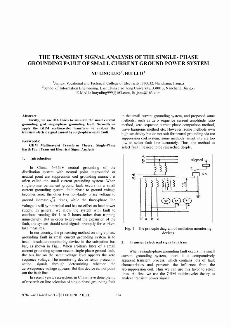
In our country, the processing method on single-phase grounding fault in small current grounding system is to install insulation monitoring device in the substation bus bar, as shown in Fig.l. When arbitrary lines of a small current grounding system occurs single-phase ground fault, the bus bar on the same voltage level appears the zero sequence voltage. The monitoring device sends protection action signals through determining whether the zero-sequence voltage appears. But this device cannot point out the fault line.
Tn recent years, researchers in China have done plenty of research on line selection of single-phase grounding fault
978-1-4673-4685-6112/$31.00 ©20 12 IEEE 334
in the small current grounding system, and proposed some methods, such as zero sequence current amplitude ratio method, zero sequence current phase comparison method, wave harmonic method etc. However, some methods own high sensitivity but do not suit for neutral grounding via arc suppression coil system; some methods' sensitivity are too low to select fault line accurately. Thus, the method to select fault line need to be researched deeply.
Fig. 1 The principle diagram of insulation monitoring devices
2. T ransient electrical signal analysis
When a single-phase grounding fault occurs in a small current grounding system, there is a comparatively apparent transient process, which contains lots of fault characteristics and prevents the influence trom the arc-suppression coil. Thus we can use this favor to select lines. At first, we use the OHM multiwavelet theory to analyze transient power signal.
2. 1. GHM multiwavelet theory overview
As a new digital technology, wavelet transform has been widely applied in image processing, data compression, signal analysis and other areas after being introduced to the engineering zone. Due to the quick attenuation and the transient waveform of wavelet function, it will be of the incomparable advantages applying wavelet transform to the transient process analysis domain. As a new development, multi wavelet is defined by two or more than two functions as wavelets generated by a scaling function. Symmetry, orthogonality, short support, high order vanishing moments are important properties in signal processing. It has been proved that real coefficient wavelet cannot have all the natures at the same time, which limits the application of wavelet. While multiwavelet can own these properties at the same time.
GHM [1] multiwavelet is a r=2 continuous, symmetrical compactly supported multiwavelet, which is constructed by Geronimo, Hardin, Massopust [2] using Fractal interpolation methods. The scaling
function f/J(t) = [¢I (t), ¢2 (t)]! and the multiwavelet
function VJ(t)=[vJ(t),vJ(t))I respectively satisfy the
corresponding scaling equations.
[91(t)] 3 [9\2t-k)] (1) (J(t)= 92(t) =..fit;,Hk 92(2t-k)' VtER
IfI{t) = [l/(t)] = J2Iq [¢:C2t-k)], 'litER (2)
vlCt) k�O ¢ C2t-k)
Tn which Hk and Gk (k = 0,1,2,3 ) are 2 x 2 coefficient matrix,
When k<O or k>3, Hk and Gk are zero matrix.
GHM multiwavelet has a secondary vanish moment. LxPI/(t)dt = 0, LxPIfI\t)dt = 0, p = 0,1 (4)
335
2.2. Using GHM multiwavelet transient analysis process
Due to the multiwavelet scale function is multidimensional. The Multiwavelet system is multi-input and multi-output systems, and one-dimensional signals need pretreatment. So before using GHM muItiwavelet for the transient analysis, signals should be decomposed into each scale of different frequency bands through multiwavelet transform. And then, to obtain and analyze the information of signals in each frequency band comprehensively, we can acquire the vector coefficient of transient characteristics.
The process of using GHM multiwavelet to multi-resolution [3] analysis: The pretreatment of original
data---->The Boundary Processing (adopting the periodic extension method)---->Decomposed to the first layer then calculation the coefficient matrix of the low frequency and high frequency---->Decomposed to the N layer and calculation the coefficient matrix of low frequency and high frequency----> the reconstruction in that layer---->A post processing for the reconstruction results.
The paper applies GHM multi wavelet to decompose a transient power quality signal to 3 layers and extract wavelet coefficients
c =[C.:,, ]N/ d =[d.l� ]
NJ ( '= 1 2 3 ' N=LI2J)(5) J ci
'J d i J " , J 2k k�l 2k k�l
Calculating energy of wavelet coefficients on each layer
(j = 1,2,3) (6)
U sing wavelet coefficients as feature vectors for classification.
(7)
The normalization processing
T = [�,�,�,QpQ2,QJT IIIEII (8)
in which, IIEII is the Euclidean norm of E.
2.3. The fault simulation of small current grounding power system single phase grounding
To acquire the amplitude of zero-sequence and simulation waveform of phase, we use Matlab to simulate the single phase grounding fault in a small current grounding system. And then we apply multiwavelet algorithm to analyze and detect features of different transient electrical signals, and determine the location of transient faults.
2.3. 1. System simulation model
The Fig.2 shows the model to simulate the single phase grounding fault in a small current grounding system.
� Power Transformer
Lmel
F I[SJ Faul t generator
rjL....-·-=--_:=: :[§. Li-,i,2 j 1 1 Load2 cd co� co{ l 1 1
*++
Fig. 2 The simulation model diagram of 10KV voltage distribution grid system
As shown in Fig.2, the 10kv voltage distribution grid has two outlets. The power is the ideal voltage source, line voltage is 10KV, frequency is 50Hz, the phase angle is 0 degrees, and the internal connection is Y connection.
As for the simulation parameter, the start time is Os, the stop time is 0.3s, the grounding time of phase A of line 1 is O.ls, the time of troubleshooting is O.2s, and sampling at 20KHZ and 400 points per cycle.
The type of solve program: ode23bt (stifflNDF), relative tolerance e-5, other parameters are automatic.
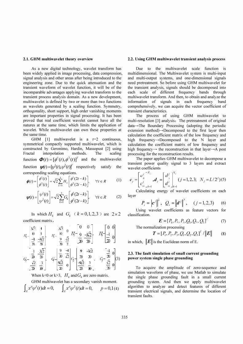
2.3.2. The result of simulation analysis
336
Zero-sequence current amli tude of the fault line
1 ��t ..
: u :1 : . :\ : � °O�--�----��---L-----L�--�----J 1 roo 2000 Wl 4000 5000 e:m
R�� i-t ___ m_o_l d _v...l;a: .... l�:*:��h e ���:._::""" a ::...er ... d_l ___ -J� o :a:: 1000 19]
mold value of the second layer d2
mold value ·of the third layer d3
Fig. 3(b). The zero sequence current amplitude of wavelet analysis diagram of fault line 1
The third layer of the decomposition result shows that the wavelet coefficients of 124-149 and 250-277 points are large, corresponding to 0.0992s � 0.1192s (Interval time is 0.02s), 0.2 � 0.2216 (Interval time is 0.0216s) in the time domain. This indicates that signal in these two periods appears transient phenomenon. After the fault occurring 0.02s, the zero sequence current reaches the maximum value, and the high frequency component becomes larger. While the system returned to normal after the troubleshooting 0.02216s, in the period of 0.1192s � 0.2216s, amplitude average is 64.897, phase average IS 156.94 degrees.
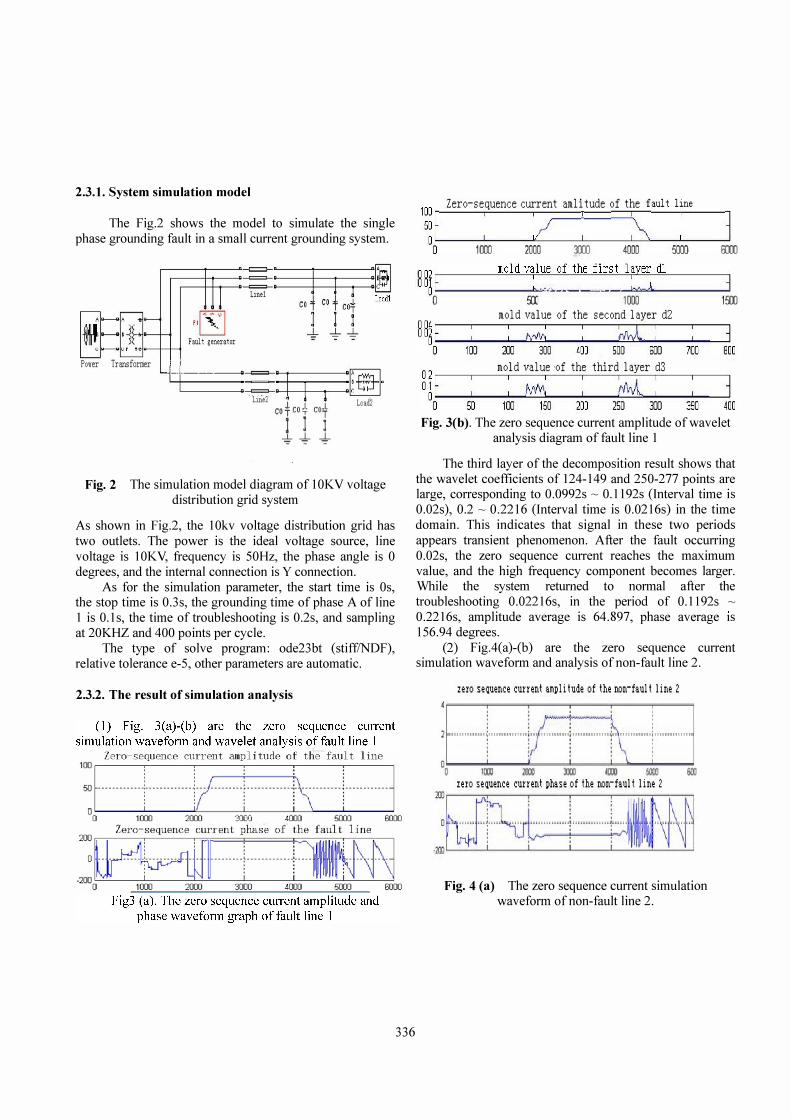
(2) Fig.4(a)-(b) are the zero sequence current simulation waveform and analysis of non-fault line 2.
zero sequence current am�l i tude of the non-taul t line 2
:l''''''''''''I'''''''''''''�''''''''l'''''-'''''E''''''''I''''''''''''''1 c � � � � m �
zero seQuence current �hase of the non-taul t line 1
Fig. 4 (a) The zero sequence current simulation waveform of non-fault line 2.

Zero-seQuence current am:Dl i tude of the non-faul t line 2
�L_: I \: D 1000 :lOOO 3Q(][ 4DOO flIIl !lOOO
mol d val ue of Ihe fi rsl layer dl
U��o!-f ___ .�� . _ � � _ . . ._. �_j. __ _ _ _ _ .J 6\ 0 I ! 1500
mol d val ue of Ihe second layer d2 'HM ---.,--_.- - - - __ --_ ...... --, 11.02
°0 100 :.al :lOll .000 em fiCO 700 8DQ
o�f mol d val ue of Ihe Ihi rd layer d3
: : � : : � : : j °0 50 100 150 XC) :I!iIJ 3tIO � .coo
Fig. 4 (b) The zero sequence current amplitude of wavelet analysis diagram of non-fault line 2.
The zero sequence current amplitude wavelet analysis result of non fault line 2 in the third layer shows that the wavelet modulus values is large since 124 points, corresponding to 0.0992s in time domain, from this point to the time of fault ending, amplitude average is 2.7173, phase average is 87.639 degrees.
(3) The multiwavelet statistical results of fault line 1 and non-faulty line 2 are shown in Table 1.
Table 1 the multiwavelet statistical results of zero sequence current amplitudes of fault lines 1 and non-faulty line 2
Fault line I Non-fault line 2
Wavelet Standard Standard
coeffi ci ent Mean deviation Mean deviation
model
DI 0.000321 0.000889 0.0001032 0.0002860
6 4
D2 0.001753 0.004748 0.0005927 0.0015236
6 7
D3 0.010252 0.026901 0.0035999 0.0079185
From the Table, we can see the wavelet coefficients of the zero sequence current of fault line are obviously higher than non-fault line. According to the analysis, the transient zero sequence amplitude and phase of fault line and non-fault line apparently exist different features. Moreover, the features are immune to the effect of the arc-suppression coil which is of great advantage for fault line selection.
Thus, we can use the transient zero sequence amplitude and phase, and multi wavelet coefficient energy as the basis of fault line selection
337
3. Conclusions
Due to the occurring randomness, short duration and non-stationary characteristics of the transient electrical signal [4], [5], traditional Fourier analysis cannot complete the extraction of the signal transient characteristics. However, Wavelet transform owns good time-frequency localization characteristic and its self-adaptive signal makes the signal singularity be characterized by the modulus maxima of wavelet. So, based on GHM multiwavelet to detect and analysis the transient electrical signal of single-phase grounding fault, we can accurately determine the start and end time of single-phase grounding fault of transient electrical signal, which is favorable to the extraction of fault characteristic parameters.
With the application and mature of modem microcomputer relay protection technology [6], [7], it is entirely achievable to collect, record and analyze the transient electrical signal of single-phase grounding fault, and select the fault line to protect the system.
References
[1] Geronimo J S, Hardin D P, Massopust P R, "Fractal functions and wavelet expansion based on a several scaling functions", SIAM. lApprox.Theory, vo1.78, pp.373-40 1,1994.
[2] Liu zhi gang, He zheng you, and Qian qing quan,"Research progress of multi wavelet and its application in power system", Automation of electric power systems, voI.28,no.ll ,pp.90-96,2004.
[3] Ren zheng, Huang qun gu, and Huang wen ying,"Multilevel multi-resolution analysis and its application in electric power system", Power system technology, vol.25, no.l0,pp. 5-8,Jun.2002.
[4] He jia Ii and Hong cong jU,"The principle of power system relay protection", Beijing: China Electric Power Press.
[5] IEEE Tutorial Course (Course coordinator: M. S. Sachdev),"Microprocessor Relays and Protection Systems", The Institute of Electrical and Electronics Engineering, Inc.1987.
[6] Wang wei jian,"the principle power system relay protection", Beijing: Tsinghua University press, 1992.
[7] Chen de shu,"the principle and technology of computer relay protection", Beijing: China Electric Power Press, 1998.