the sagnac effect and pure geometry - servizi nazionali · the sagnac effect and pure geometry...
TRANSCRIPT
The Sagnac effect and pure geometryAngelo Tartaglia and Matteo Luca Ruggiero Citation: American Journal of Physics 83, 427 (2015); doi: 10.1119/1.4904319 View online: http://dx.doi.org/10.1119/1.4904319 View Table of Contents: http://scitation.aip.org/content/aapt/journal/ajp/83/5?ver=pdfcov Published by the American Association of Physics Teachers Articles you may be interested in Temperature insensitive refractive index sensor based on single-mode micro-fiber Sagnac loop interferometer Appl. Phys. Lett. 104, 181906 (2014); 10.1063/1.4876448 Transmission and temperature sensing characteristics of a selectively liquid-filled photonic-bandgap-fiber-basedSagnac interferometer Appl. Phys. Lett. 100, 141104 (2012); 10.1063/1.3699026 Sagnac-loop phase shifter with polarization-independent operation Rev. Sci. Instrum. 82, 013106 (2011); 10.1063/1.3514984 Sagnac interferometric switch utilizing Faraday rotation J. Appl. Phys. 105, 07E702 (2009); 10.1063/1.3058627 Magnetic and electrostatic Aharonov–Bohm effects in a pure mesoscopic ring Low Temp. Phys. 23, 312 (1997); 10.1063/1.593401
This article is copyrighted as indicated in the article. Reuse of AAPT content is subject to the terms at: http://scitation.aip.org/termsconditions. Downloaded to IP:
130.192.119.93 On: Tue, 21 Apr 2015 17:40:31
The Sagnac effect and pure geometry
Angelo Tartagliaa) and Matteo Luca RuggieroDISAT, Politecnico di Torino, Corso Duca degli Abruzzi 24, Torino, Italy and INFN, Sezione di Torino,Via Pietro Giuria 1, Torino, Italy
(Received 24 July 2014; accepted 2 December 2014)
The Sagnac effect is usually deemed to be a special-relativistic effect produced in an
interferometer when the device is rotating. Two light beams traveling around the interferometer in
opposite directions require different times of flight to complete their closed path, giving rise to a
phase shift proportional to the angular velocity of the apparatus. Here, we show that the same result
can be obtained in the absence of rotation, when there is relative motion (be it inertial or not)
between the source/receiver of light and the interferometer. Our argument will use both a simple
algebraic analysis and a plain geometric approach in flat spacetime. We present an explicit
example to illustrate our point and briefly discuss other apparently correct interpretations of the
Sagnac effect, including an analogy to the Aharonov-Bohm effect. Finally, we sketch a possible
application of the non-rotational Sagnac effect. VC 2015 American Association of Physics Teachers.
[http://dx.doi.org/10.1119/1.4904319]
I. INTRODUCTION
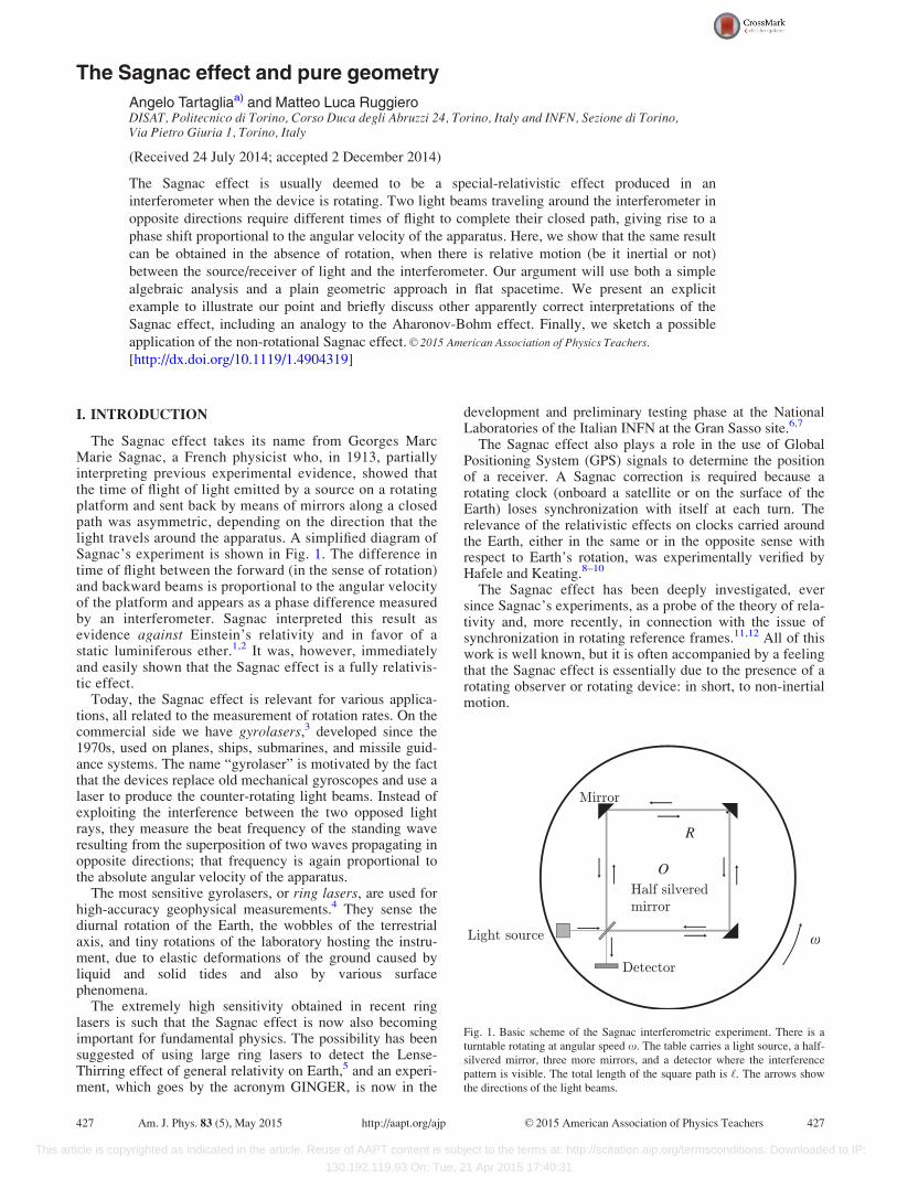
The Sagnac effect takes its name from Georges MarcMarie Sagnac, a French physicist who, in 1913, partiallyinterpreting previous experimental evidence, showed thatthe time of flight of light emitted by a source on a rotatingplatform and sent back by means of mirrors along a closedpath was asymmetric, depending on the direction that thelight travels around the apparatus. A simplified diagram ofSagnac’s experiment is shown in Fig. 1. The difference intime of flight between the forward (in the sense of rotation)and backward beams is proportional to the angular velocityof the platform and appears as a phase difference measuredby an interferometer. Sagnac interpreted this result asevidence against Einstein’s relativity and in favor of astatic luminiferous ether.1,2 It was, however, immediatelyand easily shown that the Sagnac effect is a fully relativis-tic effect.
Today, the Sagnac effect is relevant for various applica-tions, all related to the measurement of rotation rates. On thecommercial side we have gyrolasers,3 developed since the1970s, used on planes, ships, submarines, and missile guid-ance systems. The name “gyrolaser” is motivated by the factthat the devices replace old mechanical gyroscopes and use alaser to produce the counter-rotating light beams. Instead ofexploiting the interference between the two opposed lightrays, they measure the beat frequency of the standing waveresulting from the superposition of two waves propagating inopposite directions; that frequency is again proportional tothe absolute angular velocity of the apparatus.
The most sensitive gyrolasers, or ring lasers, are used forhigh-accuracy geophysical measurements.4 They sense thediurnal rotation of the Earth, the wobbles of the terrestrialaxis, and tiny rotations of the laboratory hosting the instru-ment, due to elastic deformations of the ground caused byliquid and solid tides and also by various surfacephenomena.
The extremely high sensitivity obtained in recent ringlasers is such that the Sagnac effect is now also becomingimportant for fundamental physics. The possibility has beensuggested of using large ring lasers to detect the Lense-Thirring effect of general relativity on Earth,5 and an experi-ment, which goes by the acronym GINGER, is now in the
development and preliminary testing phase at the NationalLaboratories of the Italian INFN at the Gran Sasso site.6,7
The Sagnac effect also plays a role in the use of GlobalPositioning System (GPS) signals to determine the positionof a receiver. A Sagnac correction is required because arotating clock (onboard a satellite or on the surface of theEarth) loses synchronization with itself at each turn. Therelevance of the relativistic effects on clocks carried aroundthe Earth, either in the same or in the opposite sense withrespect to Earth’s rotation, was experimentally verified byHafele and Keating.8–10
The Sagnac effect has been deeply investigated, eversince Sagnac’s experiments, as a probe of the theory of rela-tivity and, more recently, in connection with the issue ofsynchronization in rotating reference frames.11,12 All of thiswork is well known, but it is often accompanied by a feelingthat the Sagnac effect is essentially due to the presence of arotating observer or rotating device: in short, to non-inertialmotion.
Fig. 1. Basic scheme of the Sagnac interferometric experiment. There is a
turntable rotating at angular speed x. The table carries a light source, a half-
silvered mirror, three more mirrors, and a detector where the interference
pattern is visible. The total length of the square path is ‘. The arrows show
the directions of the light beams.
427 Am. J. Phys. 83 (5), May 2015 http://aapt.org/ajp VC 2015 American Association of Physics Teachers 427
This article is copyrighted as indicated in the article. Reuse of AAPT content is subject to the terms at: http://scitation.aip.org/termsconditions. Downloaded to IP:
130.192.119.93 On: Tue, 21 Apr 2015 17:40:31
In reality, however, non-inertial motion is not necessary,and examples of papers elaborating on various aspects of theSagnac effect, without discussing the necessity of rotation,are Refs. 13–15. Indeed, a few years ago some experimentalpapers were published that claim that even if no rotation ispresent, a “generalized Sagnac effect” arises in a uniformlymoving fiber.16,17 In the present paper, we aim at addressingthis issue. That is, we show that the real ingredients of theSagnac effect are: (1) a closed circuit followed by light inopposite directions; and (2) a relative (even inertial) motionof the emitter/receiver with respect to the physical apparatussupporting the closed light path. We believe that thisapproach could be useful in teaching the foundations of rela-tivity because the calculations involved are simple andbecause they allow a deep insight into the physics of theproblem (which ultimately is connected with the relativity ofsimultaneity).
II. THE SAGNAC EFFECT
The physical principles of the Sagnac effect are explainedin full detail in the well-known paper by Post;18 they can besummarized as follows.
The Sagnac effect can easily be described in classicalterms if one assumes that the speed of light is c with respectto a static ether. For the rotating platform described in theIntroduction, one can see that if the light is going around thedevice in the same direction as the rotation, then it will takelonger for it to reach the emission point because, meanwhile,the receiver will have moved forward by a distanceD‘þ¼ vtþ, where tþ is the total time of flight and v is thevelocity of the emitter with respect to the ether; the geomet-ric length of the path is ‘. Hence, the time of flight is readfrom the following relation (‘þD‘þ)=c¼D ‘þ=v. For lightgoing around in the opposite sense, the receiver will movetowards the returning beam so that the path will be shorterby D‘� ¼ vt�, whence ð‘� D‘�Þ=c ¼ D‘�=v. Solving for tþand t� gives the time of flight difference:
Dt ¼ tþ � t� ¼2‘v
c2 � v2: (1)
An equivalent deduction can be made adopting the view-point of the rotating observer. In the observer’s referenceframe, light will be expected to have speed c – v in one direc-tion (forward) and cþ v in the other; now the path length isthe same ‘ for both (see Fig. 1). The times of flight are againdifferent and a trivial calculation reproduces Eq. (1).
It is useful to rewrite Eq. (1) in terms of the angular veloc-ity x of the platform. If R is the distance of the emitter/detec-tor from the rotation axis, then we have v¼xR. We simplifythe geometry by assuming that the light path is a circle19 atradius R, so that ‘¼ 2pR. Considering that in all practicalcases v� c, Eq. (1) can be written as
Dt � 4A � x
c2: (2)
Here A is a vector whose magnitude is equal to the areaenclosed by the path of the light beams (pR2) and is orientedperpendicular to the plane of the trajectory,20 while x is the(vector) angular velocity; the dot product projects the areainto the plane of rotation. Equation (2) is the famous Sagnac
formula, where the � symbol is usually replaced by anequals sign, although the approximation is still present.
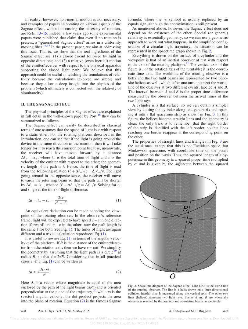
As mentioned above, however, the Sagnac effect does notdepend on the existence of the ether. Special (or general)relativity is essentially geometry, so we can use a geometricapproach to work out what happens. In the simplified config-uration of a circular light trajectory, the situation can berepresented in the spacetime graph shown in Fig. 2.
Everything is drawn on the surface of a cylinder and theviewpoint is that of an inertial observer at rest with respectto the axis of the rotating platform.21 The vertical axis of thefigure is not the rotation axis of the turntable; it is the coordi-nate time axis. The worldline of the rotating observer is ahelix and the two light beams are represented by two oppo-site helices as well, which, after one turn, intersect the world-line of the observer at two different events, labeled A and B.The interval between A and B is the proper time differencemeasured by the observer between the arrival times of thetwo light rays.
A cylinder is a flat surface, so we can obtain a simplerview by cutting the cylinder along one generatrix and open-ing it into a flat spacetime strip as shown in Fig. 3. In thisfigure, the helices become straight lines and the geometry isclear; the only trick is to remember that the right borderof the strip is identified with the left border, so that linesreaching one border reappear at the corresponding point onthe other.
The properties of straight lines and triangles in Fig. 3 arethe usual ones, except that this is not Euclidean space, butMinkowski spacetime, with coordinate time on the y-axisand position on the x-axis. Thus, the squared length of a hy-potenuse in this geometry is a squared proper time multipliedby c2 and is given by the difference between the squared
Fig. 2. Spacetime diagram of the Sagnac effect. Line OAB is the world line
of the rotating observer. The line is a helix drawn on a three-dimensional
cylinder. Inertial time is measured along the vertical axis. The other two
lines (helices) represent two light rays. Events A and B are where the
observer is reached by the counter- and co-rotating beams, respectively.
428 Am. J. Phys., Vol. 83, No. 5, May 2015 A. Tartaglia and M. L. Ruggiero 428
This article is copyrighted as indicated in the article. Reuse of AAPT content is subject to the terms at: http://scitation.aip.org/termsconditions. Downloaded to IP:
130.192.119.93 On: Tue, 21 Apr 2015 17:40:31
coordinate time span (times c2) and the square of the traveleddistance. A purely geometrical argument,21 applied to Fig. 3,leads again, to lowest order in v/c, to Eq. (2).
If one prefers to proceed analytically, the starting pointcan be the line element of Minkowski spacetime writtenusing cylindrical coordinates in space: ds2¼ c2dt2� dr2
� r2d/2� dz2. Introducing the constraints r¼R¼ constantand z¼ constant, corresponding to all physics taking placeon the rim of a disk perpendicular to the z-axis, the problemis reduced to two effective dimensions and the line elementbecomes
ds2 ¼ c2dt20 � R2d/2
0: (3)
The subscript 0 here means that the coordinates are those ofthe inertial observer.
To account for the rotation of the platform, it is convenientto introduce axes rotating together with the platform so thatthe angular coordinate becomes /¼/0�xt0. Then, weneed a Lorentz transformation between the inertial observerat rest with the axis of the platform and the inertial frameinstantaneously comoving with the observer on the rim ofthe turntable. Lorentz transformations leave the line elementunchanged, so that in the rotating reference frame it becomes
ds2 ¼ ðc2 � x2R2Þdt2 � R2d/2 � 2R2x d/ dt: (4)
On writing the previous expression in the form
ds2 ¼ g00 dt2 þ g// d/2 þ 2g0/ dt d/; (5)
and considering that for light we have ds¼ 0, we can solvefor dt:
dt ¼�g0/d/6
ffiffiffiffiffiffiffiffiffiffiffiffiffiffiffiffiffiffiffiffiffiffiffiffiffiffiffiffiffiffiffiffiffiffiffiffiffiffiffiffiffiffiffig2
0/ d/2 � g//g00 d/2q
g00
: (6)
We are interested in solutions located in the future, so wechoose dt> 0, i.e., the þ sign in Eq. (6). Under the simplifiedassumption that light moves along a circumference, if weintegrate in the two opposite directions (counterclockwise
with d/> 0 and clockwise with d/< 0) from the emissionto the absorption events, we get the expression for the co-rotating (tþ) and counter-rotating (t�) times of flight, and thedifference between them turns out to be
Dt ¼ tþ � t� ¼ �2
þ‘
g0/
g00
R d/; (7)
where ‘ is the circumference of a circle of radius R.22
Moreover, the observer measures the proper-time difference
Ds ¼ �2ffiffiffiffiffiffig00
p þ‘
g0/
g00
R d/: (8)
On substituting the explicit expressions in Eq. (4) for themetric coefficients, we obtain the following formulas for thecoordinate and proper time-of-flight differences:
Dt ¼ 4pR2x
c2 1� x2R2=c2ð Þ ; (9)
Ds ¼ 4pR2x
c2ffiffiffiffiffiffiffiffiffiffiffiffiffiffiffiffiffiffiffiffiffiffiffiffiffi1� x2R2=c2
p : (10)
At the lowest approximation order in xR=c these two expres-sions coincide, and they are in agreement with Eq. (2), withA ¼ pR2uz, where the unit vector uz points along the zdirection.
III. SAGNAC WITHOUT ROTATION
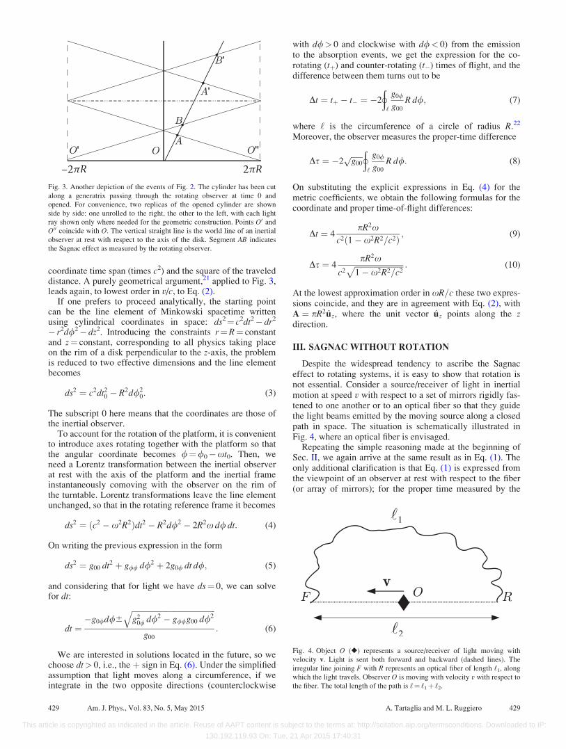
Despite the widespread tendency to ascribe the Sagnaceffect to rotating systems, it is easy to show that rotation isnot essential. Consider a source/receiver of light in inertialmotion at speed v with respect to a set of mirrors rigidly fas-tened to one another or to an optical fiber so that they guidethe light beams emitted by the moving source along a closedpath in space. The situation is schematically illustrated inFig. 4, where an optical fiber is envisaged.
Repeating the simple reasoning made at the beginning ofSec. II, we again arrive at the same result as in Eq. (1). Theonly additional clarification is that Eq. (1) is expressed fromthe viewpoint of an observer at rest with respect to the fiber(or array of mirrors); for the proper time measured by the
Fig. 3. Another depiction of the events of Fig. 2. The cylinder has been cut
along a generatrix passing through the rotating observer at time 0 and
opened. For convenience, two replicas of the opened cylinder are shown
side by side: one unrolled to the right, the other to the left, with each light
ray shown only where needed for the geometric construction. Points O0 and
O00 coincide with O. The vertical straight line is the world line of an inertial
observer at rest with respect to the axis of the disk. Segment AB indicates
the Sagnac effect as measured by the rotating observer.
Fig. 4. Object O (�) represents a source/receiver of light moving with
velocity v. Light is sent both forward and backward (dashed lines). The
irregular line joining F with R represents an optical fiber of length ‘1, along
which the light travels. Observer O is moving with velocity v with respect to
the fiber. The total length of the path is ‘¼ ‘1þ ‘2.
429 Am. J. Phys., Vol. 83, No. 5, May 2015 A. Tartaglia and M. L. Ruggiero 429
This article is copyrighted as indicated in the article. Reuse of AAPT content is subject to the terms at: http://scitation.aip.org/termsconditions. Downloaded to IP:
130.192.119.93 On: Tue, 21 Apr 2015 17:40:31
moving emitter/receiver we would instead have (withb¼ v/c)
Ds ¼ 2‘v
c2ffiffiffiffiffiffiffiffiffiffiffiffiffi1� b2
p � 2‘v
c2: (11)
No rotation, acceleration, or enclosed area appears in thisexpression. What matters is just the existence of relative(even inertial) motion and of a closed path in space. Ofcourse, with reference to Fig. 4, the velocity v is parallel tothe light rays along the path RF.
The effect we have just described and the related formula(11) have been experimentally verified by Wang, Zheng,Yao, and Langley (WZYL).16,17
Using the geometrical approach, this result is ratherobvious. In spacetime, the world lines are drawn again on a(non-circular) cylinder. The only difference is that in Fig. 2the cylinder had a circular cross section, while now the crosssection is irregular. In either case, the cylinder is a flatbidimensional Minkowski surface and, when opening it intoa plane, the graph is exactly as in Fig. 3.
It is worth noting that formula (1) also appears in Ref. 24,where it is related to the relativity of simultaneity typical ofspecial relativity.
Another aspect to clarify is related to the form of Eq. (2).The accidental presence of the area A suggested to somepeople (for instance, Refs. 25 and 26) an interpretation of theSagnac effect (at least for matter waves) as a sort ofAharonov-Bohm effect. However, this is just an analogy,which holds only at lowest relativistic order (see, e.g.,Ref. 23).
IV. A SIMPLE EXAMPLE
In order to obtain deeper insight into the Sagnac effect, letus consider a simple example where the calculation can becarried out in full detail.
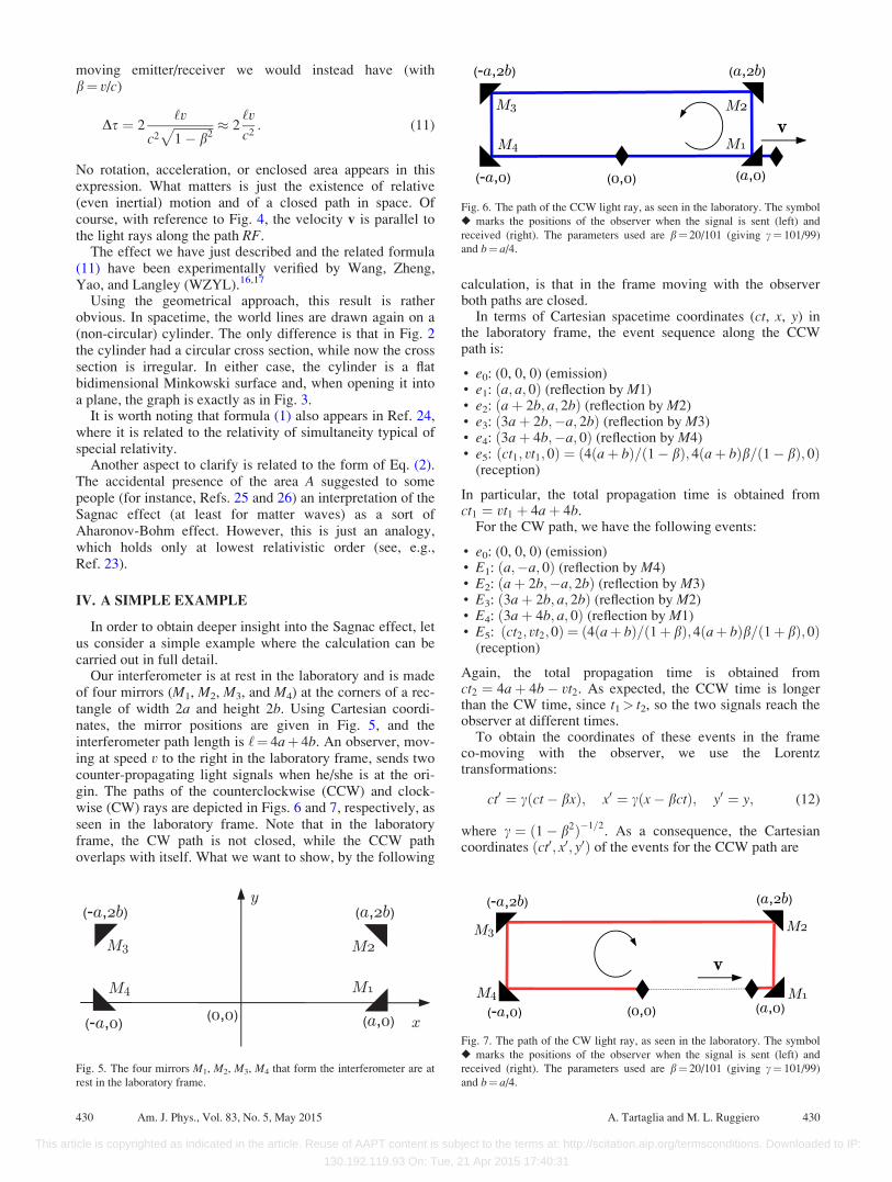
Our interferometer is at rest in the laboratory and is madeof four mirrors (M1, M2, M3, and M4) at the corners of a rec-tangle of width 2a and height 2b. Using Cartesian coordi-nates, the mirror positions are given in Fig. 5, and theinterferometer path length is ‘¼ 4aþ 4b. An observer, mov-ing at speed v to the right in the laboratory frame, sends twocounter-propagating light signals when he/she is at the ori-gin. The paths of the counterclockwise (CCW) and clock-wise (CW) rays are depicted in Figs. 6 and 7, respectively, asseen in the laboratory frame. Note that in the laboratoryframe, the CW path is not closed, while the CCW pathoverlaps with itself. What we want to show, by the following
calculation, is that in the frame moving with the observerboth paths are closed.
In terms of Cartesian spacetime coordinates (ct, x, y) inthe laboratory frame, the event sequence along the CCWpath is:
• e0: (0, 0, 0) (emission)• e1: ða; a; 0Þ (reflection by M1)• e2: ðaþ 2b; a; 2bÞ (reflection by M2)• e3: ð3aþ 2b;�a; 2bÞ (reflection by M3)• e4: ð3aþ 4b;�a; 0Þ (reflection by M4)• e5: ðct1; vt1;0Þ ¼ ð4ðaþ bÞ=ð1� bÞ; 4ðaþ bÞb=ð1� bÞ; 0Þ
(reception)
In particular, the total propagation time is obtained fromct1 ¼ vt1 þ 4aþ 4b.
For the CW path, we have the following events:
• e0: (0, 0, 0) (emission)• E1: ða;�a; 0Þ (reflection by M4)• E2: ðaþ 2b;�a; 2bÞ (reflection by M3)• E3: ð3aþ 2b; a; 2bÞ (reflection by M2)• E4: ð3aþ 4b; a; 0Þ (reflection by M1)• E5: ðct2; vt2;0Þ ¼ ð4ðaþ bÞ=ð1þ bÞ;4ðaþ bÞb=ð1þ bÞ;0Þ
(reception)
Again, the total propagation time is obtained fromct2 ¼ 4aþ 4b� vt2. As expected, the CCW time is longerthan the CW time, since t1> t2, so the two signals reach theobserver at different times.
To obtain the coordinates of these events in the frameco-moving with the observer, we use the Lorentztransformations:
ct0 ¼ cðct� bxÞ; x0 ¼ cðx� bctÞ; y0 ¼ y; (12)
where c ¼ ð1� b2Þ�1=2. As a consequence, the Cartesian
coordinates ðct0; x0; y0Þ of the events for the CCW path are
Fig. 5. The four mirrors M1, M2, M3, M4 that form the interferometer are at
rest in the laboratory frame.
Fig. 6. The path of the CCW light ray, as seen in the laboratory. The symbol
� marks the positions of the observer when the signal is sent (left) and
received (right). The parameters used are b¼ 20/101 (giving c¼ 101/99)
and b¼ a/4.
Fig. 7. The path of the CW light ray, as seen in the laboratory. The symbol
� marks the positions of the observer when the signal is sent (left) and
received (right). The parameters used are b¼ 20/101 (giving c¼ 101/99)
and b¼ a/4.
430 Am. J. Phys., Vol. 83, No. 5, May 2015 A. Tartaglia and M. L. Ruggiero 430
This article is copyrighted as indicated in the article. Reuse of AAPT content is subject to the terms at: http://scitation.aip.org/termsconditions. Downloaded to IP:
130.192.119.93 On: Tue, 21 Apr 2015 17:40:31
• e0: (0, 0, 0) (emission)• e1: ðcð1� bÞa; cð1� bÞa; 0Þ (reflection by M1)• e2: ðcð1� bÞaþ 2cb; cð1� bÞa� 2cbb; 2bÞ (reflection by
M2)• e3: ðcð3þ bÞaþ 2cb;�cð1þ 3bÞa� 2cbb; 2bÞ (reflection
by M3)• e4: ðcð3þ bÞaþ 4cb;�cð1þ 3bÞa� 4cbb; 0Þ (reflection
by M4)• e5: ð4cð1þ bÞðaþ bÞ; 0; 0Þ (reception)
For the CW path, we have the following coordinates:
• e0: (0, 0, 0) (emission)• E1: ðcð1þ bÞa;�cð1þ bÞa; 0Þ (reflection by M4)• E2: ðcð1þ bÞaþ 2cb;�cð1þ bÞa� 2cbb; 2bÞ (reflection
by M3)• E3: ðcð3� bÞaþ 2cb; cð1� 3bÞa� 2cbb; 2bÞ (reflection
by M2)• E4: ðcð3� bÞaþ 4cb; cð1� 3bÞa� 4cbb; 0Þ (reflection
by M1)• E5: ð4cð1� bÞðaþ bÞ; 0; 0Þ (reception)
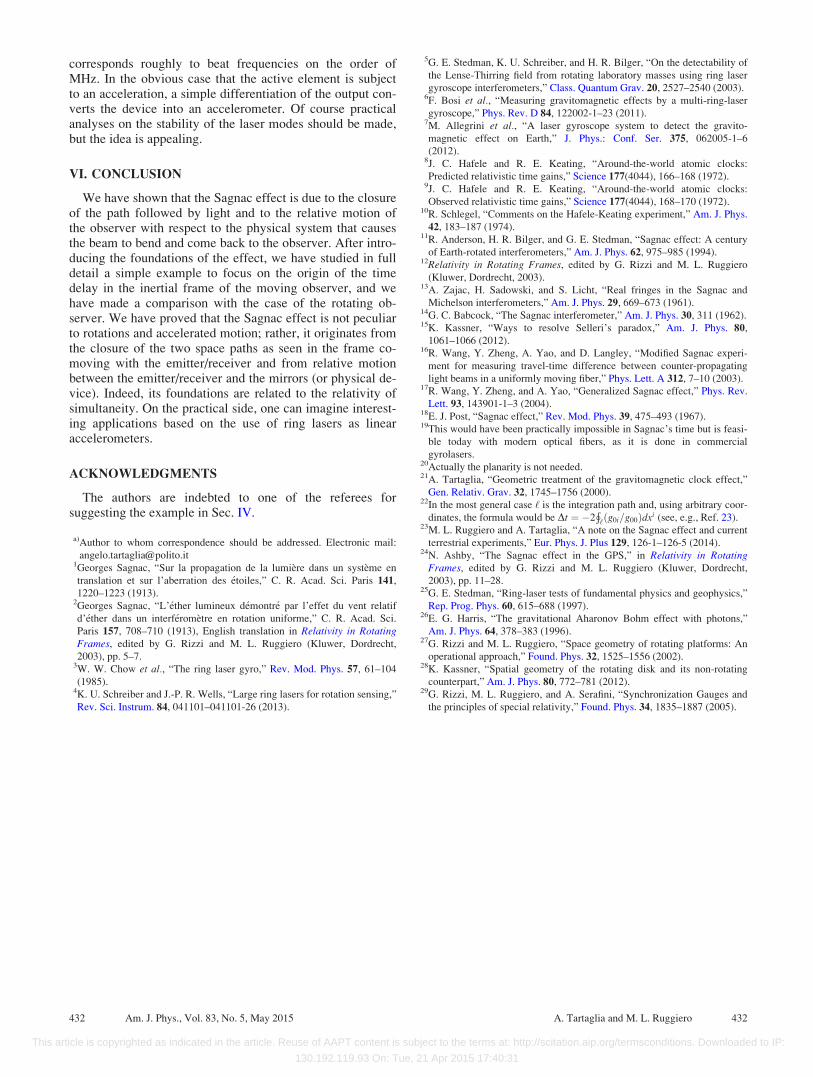
These collections of event coordinates show that in the mov-ing frame the two paths are closed. In particular, the CCWpath is a polygon whose vertices have the following ðx0; y0Þcoordinates: ð0; 0Þ; ðcð1� bÞa; 0Þ; ðcð1� bÞa� 2cbb; 2bÞ;ð�cð1þ 3bÞa� 2cbb; 2bÞ; ð�cð1þ 3bÞa� 4cbb; 0Þ. Theshape of this polygon is depicted in Fig. 8, and its perimeter isgiven by ‘1 ¼ 4cð1þ bÞðaþ bÞ. Since the traversal time isgiven from event e5 as t01 ¼ 4cð1þ bÞðaþ bÞ=c, we see thatthe average traversal speed is ‘1=t01 ¼ c.
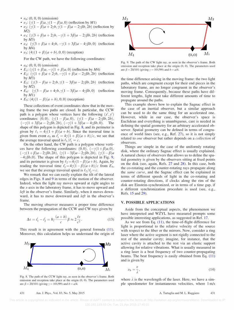
On the other hand, the CW path is a polygon whose verti-ces have the following coordinates: ð0;0Þ; ð�cð1þbÞa;0Þ;ð�cð1þbÞa�2cbb;2bÞ; ðcð1�3bÞa�2cbb;2bÞ; ðcð1�bÞa�4cbb;0Þ. The shape of this polygon is depicted in Fig. 9,and its perimeter is given by ‘2¼4cð1�bÞðaþbÞ. Again, byreading the traversal time t02¼4cð1�bÞðaþbÞ=c from E5,we see that the average traversal speed is ‘2=t02¼ c.
We remark that we can easily explain the tilt of the lateraledges in Figs. 8 and 9 in terms of the motion of the observer.Indeed, when the light ray moves upward at right angles tothe x-axis in the laboratory frame, it has to move upward andleft in the observer’s frame. Similarly, when it moves down-ward, it has to move downward and left in the observer’sframe.
The moving observer measures a proper time differencebetween the propagation of the CCW and CW rays given by
Ds ¼ t01 � t02 ¼ 8caþ bð Þ
cb � 2
‘v
c2: (13)
This result is in agreement with the general formula (11).Moreover, this calculation helps us understand the origin of
the time difference arising in the moving frame: the two lightpaths, which are congruent except for their end pieces in thelaboratory frame, are no longer congruent in the observer’smoving frame. Consequently, because these paths have dif-ferent lengths, light must take different amounts of time topropagate around the paths.
This example shows how to explain the Sagnac effect inthe case of an inertial observer, but a similar approachcan be used to do the same thing for an accelerated one.However, while in our case, the observer’s space isEuclidean and everything is unambiguous, care is needed indefining the spatial geometry for an arbitrary accelerated ob-server. Spatial geometry can be defined in terms of congru-ence of world lines (see, e.g., Ref. 27), so it is not simplyrelated to one observer but rather depends on a collection ofobservers.
Things are simple in the case of the uniformly rotatingdisk, where the ordinary Sagnac effect is usually explained.A natural choice of observers that allows us to define the spa-tial geometry is given by the observers sitting at fixed pointson the disk (see, again, Refs. 27 and 28). In this case, boththe co-rotating and the counter-rotating rays propagate alongthe same curve, and the Sagnac effect can be explained interms of different speeds of light in the co-rotating andcounter-rotating directions, if clocks along the rim of thedisk are Einstein-synchronized, or in terms of a time gap, ifa different synchronization procedure is used (see, e.g.,Refs. 15 and 29).
V. POSSIBLE APPLICATIONS
Aside from the conceptual aspects, the phenomenon wehave interpreted and WZYL have measured prompts somepossible interesting applications, as suggested in Ref. 17.
As we see from Eq. (11), the time-of-flight difference forlight is proportional to the relative velocity of the sourcewith respect to the fiber or the mirrors. Now, consider a ringlaser where the active segment is not rigidly connected to therest of the annular cavity; imagine, for instance, that theactive cavity is attached to the rest via an elastic supportallowing for relative vibrations. What is usually measured ina ring laser is a beat frequency of two counter-propagatingbeams. The beat frequency is easily obtained from Eq. (11)and is given by
�b ¼v
k; (14)
where k is the wavelength of the laser. Here, we have a sim-ple speedometer for instantaneous velocities, where 1 m/s
Fig. 8. The path of the CCW light ray, as seen in the observer’s frame. Both
emission and reception take place at the origin (0, 0). The parameters used
are b¼ 20/101 (giving c¼ 101/99) and b¼ a/4.
Fig. 9. The path of the CW light ray, as seen in the observer’s frame. Both
emission and reception take place at the origin (0, 0). The parameters used
are b¼ 20/101 (giving c¼ 101/99) and b¼ a/4.
431 Am. J. Phys., Vol. 83, No. 5, May 2015 A. Tartaglia and M. L. Ruggiero 431
This article is copyrighted as indicated in the article. Reuse of AAPT content is subject to the terms at: http://scitation.aip.org/termsconditions. Downloaded to IP:
130.192.119.93 On: Tue, 21 Apr 2015 17:40:31
corresponds roughly to beat frequencies on the order ofMHz. In the obvious case that the active element is subjectto an acceleration, a simple differentiation of the output con-verts the device into an accelerometer. Of course practicalanalyses on the stability of the laser modes should be made,but the idea is appealing.
VI. CONCLUSION
We have shown that the Sagnac effect is due to the closureof the path followed by light and to the relative motion ofthe observer with respect to the physical system that causesthe beam to bend and come back to the observer. After intro-ducing the foundations of the effect, we have studied in fulldetail a simple example to focus on the origin of the timedelay in the inertial frame of the moving observer, and wehave made a comparison with the case of the rotating ob-server. We have proved that the Sagnac effect is not peculiarto rotations and accelerated motion; rather, it originates fromthe closure of the two space paths as seen in the frame co-moving with the emitter/receiver and from relative motionbetween the emitter/receiver and the mirrors (or physical de-vice). Indeed, its foundations are related to the relativity ofsimultaneity. On the practical side, one can imagine interest-ing applications based on the use of ring lasers as linearaccelerometers.
ACKNOWLEDGMENTS
The authors are indebted to one of the referees forsuggesting the example in Sec. IV.
a)Author to whom correspondence should be addressed. Electronic mail:
[email protected] Sagnac, “Sur la propagation de la lumiere dans un systeme en
translation et sur l’aberration des �etoiles,” C. R. Acad. Sci. Paris 141,
1220–1223 (1913).2Georges Sagnac, “L’�ether lumineux d�emontr�e par l’effet du vent relatif
d’�ether dans un interf�erometre en rotation uniforme,” C. R. Acad. Sci.
Paris 157, 708–710 (1913), English translation in Relativity in RotatingFrames, edited by G. Rizzi and M. L. Ruggiero (Kluwer, Dordrecht,
2003), pp. 5–7.3W. W. Chow et al., “The ring laser gyro,” Rev. Mod. Phys. 57, 61–104
(1985).4K. U. Schreiber and J.-P. R. Wells, “Large ring lasers for rotation sensing,”
Rev. Sci. Instrum. 84, 041101–041101-26 (2013).
5G. E. Stedman, K. U. Schreiber, and H. R. Bilger, “On the detectability of
the Lense-Thirring field from rotating laboratory masses using ring laser
gyroscope interferometers,” Class. Quantum Grav. 20, 2527–2540 (2003).6F. Bosi et al., “Measuring gravitomagnetic effects by a multi-ring-laser
gyroscope,” Phys. Rev. D 84, 122002-1–23 (2011).7M. Allegrini et al., “A laser gyroscope system to detect the gravito-
magnetic effect on Earth,” J. Phys.: Conf. Ser. 375, 062005-1–6
(2012).8J. C. Hafele and R. E. Keating, “Around-the-world atomic clocks:
Predicted relativistic time gains,” Science 177(4044), 166–168 (1972).9J. C. Hafele and R. E. Keating, “Around-the-world atomic clocks:
Observed relativistic time gains,” Science 177(4044), 168–170 (1972).10R. Schlegel, “Comments on the Hafele-Keating experiment,” Am. J. Phys.
42, 183–187 (1974).11R. Anderson, H. R. Bilger, and G. E. Stedman, “Sagnac effect: A century
of Earth-rotated interferometers,” Am. J. Phys. 62, 975–985 (1994).12Relativity in Rotating Frames, edited by G. Rizzi and M. L. Ruggiero
(Kluwer, Dordrecht, 2003).13A. Zajac, H. Sadowski, and S. Licht, “Real fringes in the Sagnac and
Michelson interferometers,” Am. J. Phys. 29, 669–673 (1961).14G. C. Babcock, “The Sagnac interferometer,” Am. J. Phys. 30, 311 (1962).15K. Kassner, “Ways to resolve Selleri’s paradox,” Am. J. Phys. 80,
1061–1066 (2012).16R. Wang, Y. Zheng, A. Yao, and D. Langley, “Modified Sagnac experi-
ment for measuring travel-time difference between counter-propagating
light beams in a uniformly moving fiber,” Phys. Lett. A 312, 7–10 (2003).17R. Wang, Y. Zheng, and A. Yao, “Generalized Sagnac effect,” Phys. Rev.
Lett. 93, 143901-1–3 (2004).18E. J. Post, “Sagnac effect,” Rev. Mod. Phys. 39, 475–493 (1967).19This would have been practically impossible in Sagnac’s time but is feasi-
ble today with modern optical fibers, as it is done in commercial
gyrolasers.20Actually the planarity is not needed.21A. Tartaglia, “Geometric treatment of the gravitomagnetic clock effect,”
Gen. Relativ. Grav. 32, 1745–1756 (2000).22In the most general case ‘ is the integration path and, using arbitrary coor-
dinates, the formula would be Dt ¼ �2Þ‘ðg0i=g00Þdxi (see, e.g., Ref. 23).
23M. L. Ruggiero and A. Tartaglia, “A note on the Sagnac effect and current
terrestrial experiments,” Eur. Phys. J. Plus 129, 126-1–126-5 (2014).24N. Ashby, “The Sagnac effect in the GPS,” in Relativity in Rotating
Frames, edited by G. Rizzi and M. L. Ruggiero (Kluwer, Dordrecht,
2003), pp. 11–28.25G. E. Stedman, “Ring-laser tests of fundamental physics and geophysics,”
Rep. Prog. Phys. 60, 615–688 (1997).26E. G. Harris, “The gravitational Aharonov Bohm effect with photons,”
Am. J. Phys. 64, 378–383 (1996).27G. Rizzi and M. L. Ruggiero, “Space geometry of rotating platforms: An
operational approach,” Found. Phys. 32, 1525–1556 (2002).28K. Kassner, “Spatial geometry of the rotating disk and its non-rotating
counterpart,” Am. J. Phys. 80, 772–781 (2012).29G. Rizzi, M. L. Ruggiero, and A. Serafini, “Synchronization Gauges and
the principles of special relativity,” Found. Phys. 34, 1835–1887 (2005).
432 Am. J. Phys., Vol. 83, No. 5, May 2015 A. Tartaglia and M. L. Ruggiero 432
This article is copyrighted as indicated in the article. Reuse of AAPT content is subject to the terms at: http://scitation.aip.org/termsconditions. Downloaded to IP:
130.192.119.93 On: Tue, 21 Apr 2015 17:40:31