the pros and cons of 3d modeling paradigms: direct modeling and history-based modeling
TRANSCRIPT

The Pros and Cons of
3D Modeling Paradigms:
Direct Modeling and
History-based Modeling

Thank You To Our Sponsor

This webinar will be available afterwards at
www.designworldonline.com & email
Q&A at the end of the presentation
Hashtag for this webinar: #DWwebinar
Before We Start

Moderator Presenters
Barb Schmitz Design World
Brian Thompson PTC
Chad Jackson Lifecycle Insights
Dan Staples Siemens PLM
Software
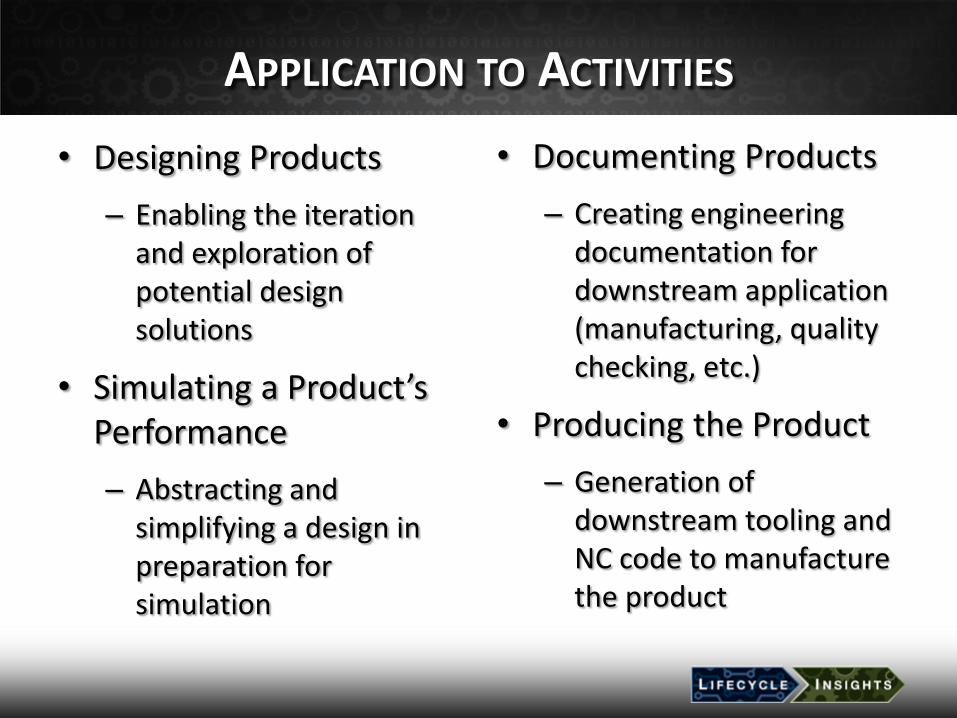
APPLICATION TO ACTIVITIES
• Designing Products
– Enabling the iteration and exploration of potential design solutions
• Simulating a Product’s Performance
– Abstracting and simplifying a design in preparation for simulation
• Documenting Products
– Creating engineering documentation for downstream application (manufacturing, quality checking, etc.)
• Producing the Product
– Generation of downstream tooling and NC code to manufacture the product
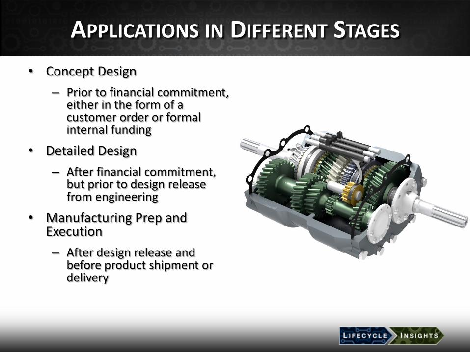
APPLICATIONS IN DIFFERENT STAGES
• Concept Design
– Prior to financial commitment, either in the form of a customer order or formal internal funding
• Detailed Design
– After financial commitment, but prior to design release from engineering
• Manufacturing Prep and Execution
– After design release and before product shipment or delivery

MODELING PARADIGMS: HISTORY-BASED
• Geometry built progressively with features (sketch-based, edge based, etc.)
• Interdependencies built up between features
• Build history of model is preserved in a specific order
• Changes enabled by modifying existing features

MODELING PARADIGMS: DIRECT
• Geometry selected, then manipulated
• Selection or manipulation not constrained by how the geometry was created
• Build history of model not preserved
• Can include parametric modifications

ITS NOT JUST ABOUT 3D
• Sketching Tools
– Constraints enforce properties like parallelism, tangency and the like
– Constraints on an entire set of 2D entities constantly applied during changes
• Drafting Tools
– Properties applied at creation, but not persisted during changes

Concept Design:
Industry Trends and CAD
Development Impacts
Brian Thompson
Vice President, PTC Creo Product Management
February 2014

11
Companies want more concept designs
created in existing time
Companies need Speed and Flexibility
to support the Concept Effort
Concept Design Business Challenges
© 2014 PTC
92% say that they would benefit immensely by exploring
more design alternatives during concept design
Only 16% use 3D modeling tools at this point in the process
* 2011 surveys conducted by PTC: CAD and Complexity (300+ respondents), Concept Design Challenges (200+ respondents),
and 2D and 3D CAD Trends (7,000+ respondents)

12
Teams are wasting time
during this stage recreating data
Teams are duplicating effort
not being able to re-use data
Concept Design Business Challenges
© 2014 PTC
68% say that concept designs typically evolve
by partially or heavily leveraging existing designs
61% say concept drawings/sketches need to be recreated to
support detailed engineering stages
* 2011 surveys conducted by PTC: CAD and Complexity (300+ respondents), Concept Design Challenges (200+ respondents),
and 2D and 3D CAD Trends (7,000+ respondents)

13
Concept Design CAD Implications
Concept Design
Industrial Design 61% say concepts need to
be recreated for detailed design1
• Improved Industrial Design Tools – Better Efficiency – Simpler Paradigm
• 100% Reuse of Freeform surfaces
1 PTC survey of 7,000 manufacturing organizations, October, 2011

14
Concept Design CAD Implications
Concept Design
Industrial Design 2D Engineering
Design
1 PTC survey of 7,000 manufacturing organizations, October, 2011
65% of new concepts
are captured in 2D1
• Purpose Built 2D Design Environment
• Collaborative Connection with 3D
• 100% Reuse of 2D Concepts
• Improved Industrial Design Tools – Better Efficiency – Simpler Paradigm
• 100% Reuse of Freeform surfaces

15
Concept Design CAD Implications
Concept Design
Industrial Design 2D Engineering
Design
3D Engineering
Design 68% leverage existing
designs in new concepts1
1 PTC survey of 7,000 manufacturing organizations, October, 2011
• Purpose Built 2D Design Environment
• Collaborative Connection with 3D
• 100% Reuse of 2D Concepts
• Greater Design Flexibility
• Maintain Existing Design Intent
• 3D Design Paradigm Choice
• Improved Industrial Design Tools – Better Efficiency – Simpler Paradigm
• 100% Reuse of Freeform surfaces
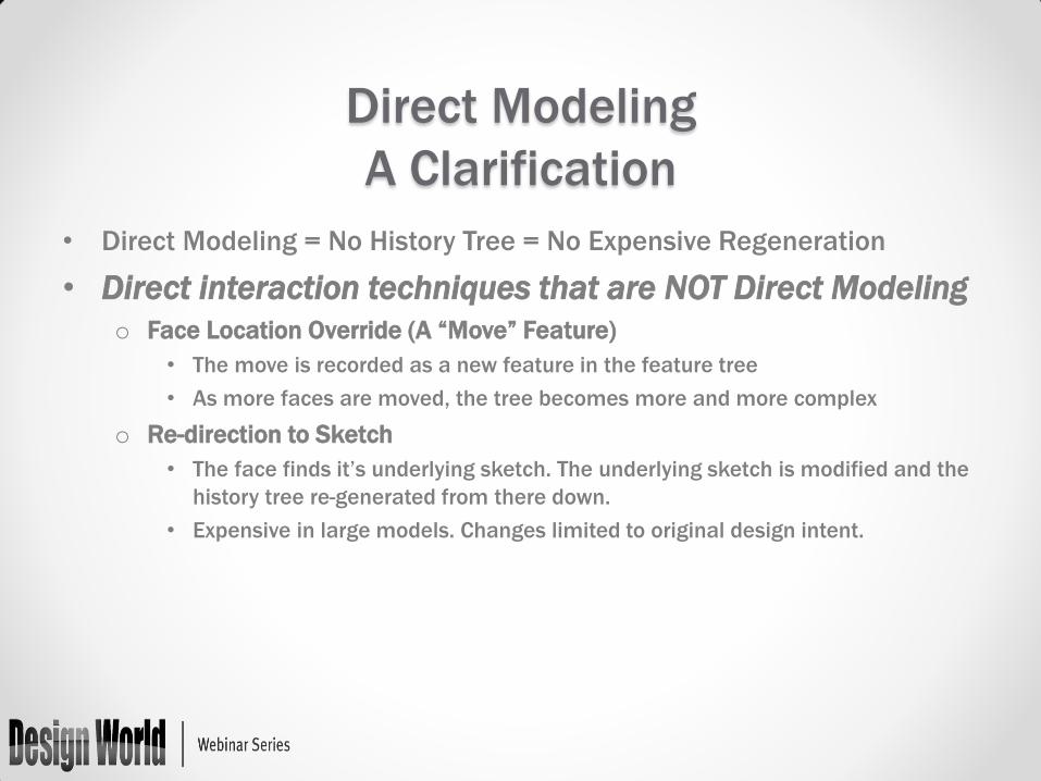
Direct Modeling
A Clarification
• Direct Modeling = No History Tree = No Expensive Regeneration
• Direct interaction techniques that are NOT Direct Modeling
o Face Location Override (A “Move” Feature)
• The move is recorded as a new feature in the feature tree
• As more faces are moved, the tree becomes more and more complex
o Re-direction to Sketch
• The face finds it’s underlying sketch. The underlying sketch is modified and the
history tree re-generated from there down.
• Expensive in large models. Changes limited to original design intent.

Pros and Cons of History-based Modeling
History-based Modeling
Dimension- Driven
Inflexible
Scales poorly on many-featured
parts
Requires pre-planning
Highly Automated
Feature-based
Indirect
More Desirable Less Desirable Less Desirable

History-free (Direct) Modeling
Flexible editing
Feature-less
Direct interaction
Weak dimension-driven
editing
Little design automation
Scales well
More Desirable Less Desirable Less Desirable
Pros and Cons of History-free (Direct) Modeling

Users Don’t Want to Have to Choose! Incorporating the best of both worlds
History-based Modeling
Dimension- Driven
Inflexible
Scales poorly on many-featured
parts
Flexible editing
Feature-less
Direct interaction
Optimal Solution
Weak dimension-driven
editing
Little design automation
Requires pre-planning
Highly Automated
Feature-based
Synchronized Solve
Procedural Features
Driving 3D Dimensions
More… Indirect
More Desirable Less Desirable Less Desirable
Scales well
History-free (Direct) Modeling

History-based Modeling
Single, Seamless System
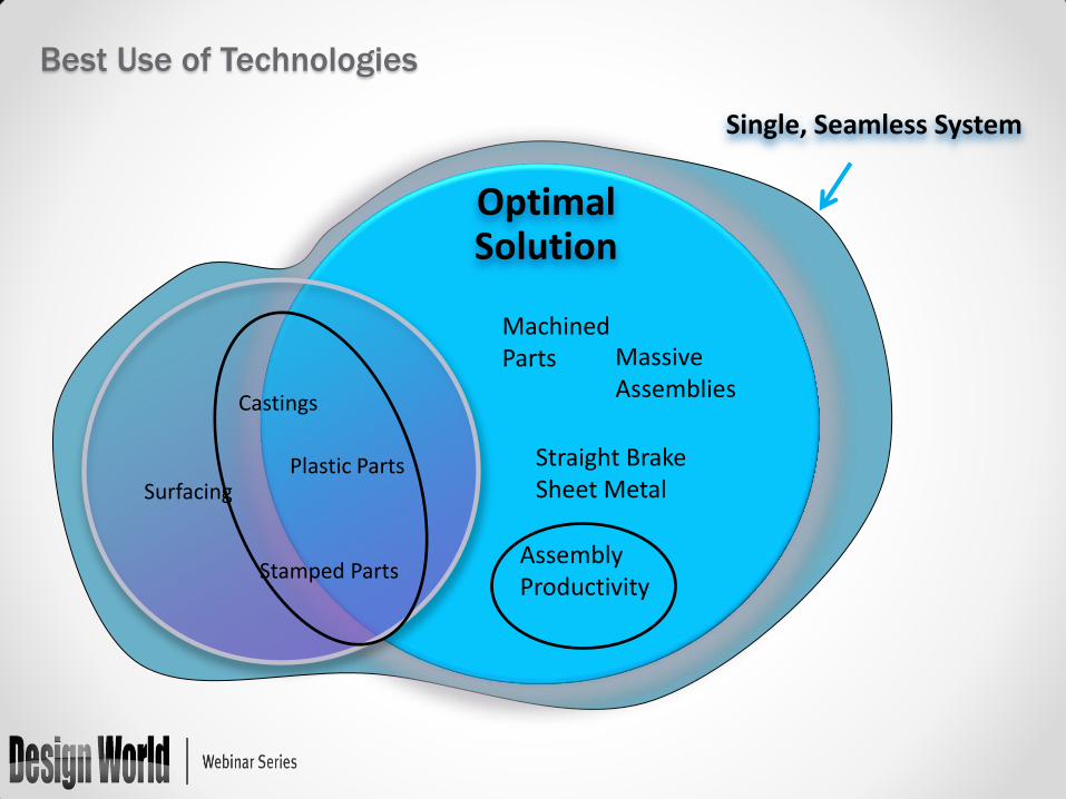
Surfacing
Castings
Plastic Parts
Stamped Parts
Massive Assemblies
Assembly Productivity
Machined Parts
Straight Brake Sheet Metal
Best Use of Technologies
Optimal Solution
Surfacing
Castings
Plastic Parts
Stamped Parts
Massive Assemblies
Assembly Productivity
Machined Parts
Straight Brake Sheet Metal
Best Use of Technologies
Single, Seamless System
Optimal Solution

Questions?
Barb Schmitz Design World [email protected]
Phone: 440-937-4251
Twitter: @DW_BarbSchmitz
Dan Staples Siemens PLM Software [email protected]
Twitter: @danstaples
Chad Jackson Lifecycle Insights [email protected]
Phone: (512) 284-8080
Twitter: @chadjackson
Brian Thompson PTC [email protected]
Phone: 781-370-5583

Thank You
This webinar will be available at
designworldonline.com & email
Tweet with hashtag #DWwebinar
Connect with Design World
Discuss this on EngineeringExchange.com
