the performer high-efficiency woodstove · 852171b-1903e u.s. environmental protection agency...
TRANSCRIPT
852171B-1903E
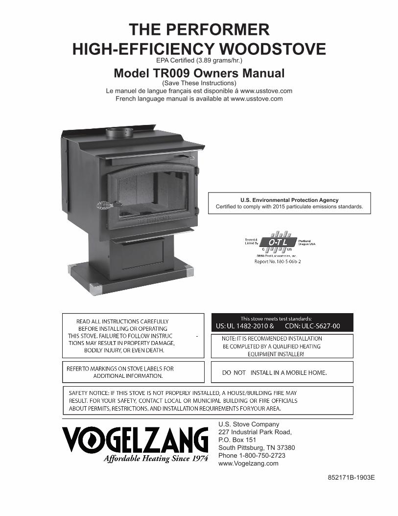
U.S. Environmental Protection Agency Certified to comply with 2015 particulate emissions standards.
THE PERFORMER HIGH-EFFICIENCY WOODSTOVE
EPA Certified (3.89 grams/hr.)
Model TR009 Owners Manual(Save These Instructions)
Le manuel de langue français est disponible á www.usstove.comFrench language manual is available at www.usstove.com
U.S. Stove Company 227 Industrial Park Road,P.O. Box 151South Pittsburg, TN 37380 Phone 1-800-750-2723www.Vogelzang.com
2
1. The installation of this stove must comply with your local building code rulings. Please observe the clearances to com-bustibles (see reference figures 10–12). Do not place furniture or other objects within the clearance area.
2. Verify that the stove is properly installed before firing the stove for the first time. After reading these instructions, if you have any doubt about your ability to complete your installation properly, you must obtain the services of a professional licensed installer familiar with all aspects of safe and correct installation.
3. DO NOT store wood, flammable liquids or other combustible materials too close to the unit. Refer to certification label on back of unit and reference figures 10–12 in this manual.
4. DO NOT INSTALL THIS STOVE IN A MOBILE HOME, MANUFACTURED HOME, TRAILER OR TENT NO EXCEP-TIONS! (HUD Federal Standard: 24 CFR Ch.XX).
5. DO NOT MODIFY THIS STOVE IN ANY WAY! DO NOT ELEVATE THIS STOVE BY ANY MEANS. (i.e. bricks under pedestal base, cement blocks) Stove base must set directly upon the solid-surface, non-combustible floor as specified in this stove instruction manual.
6. DO NOT MODIFY THIS STOVE IN ANY WAY! Stove must be installed with pedestal provided, attached as shown in the instructions. DO NOT OPERATE WITHOUT BOTTOM HEAT SHIELD – NO EXCEPTIONS. Heat Shield must be assembled and installed as shown in Assembly Instructions. Assemble only with original parts as supplied and shown in this manual. DO NOT OPERATE A STOVE THAT IS MISSING ANY PARTS! If any parts are missing or defective, please notify the dealer or manufacturer immediately. Replace missing, broken or worn parts with factory original or equivalent parts only.
7. Do not tamper with combustion air control beyond normal adjustment capacities.8. Always connect this stove to a chimney and vent to the outside. Never vent to another room or inside a building. DO
NOT CONNECT THIS UNIT TO A CHIMNEY FLUE SERVING ANOTHER APPLIANCE.9. DO NOT CONNECT A WOOD BURNING STOVE TO AN ALUMINIUM TYPE B GAS VENT. This is not safe. Use ap-
proved masonry or an Underwriters Laboratories Listed UL 103 HT / ULC-S629 Residential Type and Building Heating Appliance Chimney. Use a 6˝/152mm diameter chimney, that is high enough to give a good draft. (See specifics in Chimney Connections instructions).
10. Be sure that your chimney is safely constructed and in good repair. Have the chimney inspected by the fire depart-ment or a qualified inspector. Your insurance company should be able to recommend a qualified inspector. Chimney connector pipe must be in good condition. Replace if necessary before using stove.
11. Creosote or soot may build up in the chimney connector and chimney and cause a house/building fire. Inspect the chimney connector and chimney twice monthly during the heating season and clean if necessary. (see Service Hints).
12. In the event of a chimney fire, turn the air control to closed position, leave the building and CALL THE FIRE DEPART-MENT IMMEDIATELY! Have a clearly understood plan on how to handle a chimney fire by contacting your local fire authority for information on proper procedures in the event of a chimney fire. After the fire is out, the chimney must be cleaned and inspected for any stress or cracks before starting another fire. Check the condition of any combustibles surrounding the chimney.
13. Ashes should not be allowed to accumulate above the top of the lower primary air orifice (LPAO, air vent at front of firebox, just inside of door).
14. DISPOSAL OF ASHES Ashes should be placed in a steel container with a tight fitting lid and moved outdoors im-mediately. The closed container of ashes should be placed on a noncombustible floor or on the ground, well away from all combustible materials, pending final disposal. If the ashes are disposed of by burial in soil or otherwise locally dispersed, they should be retained in the closed container until all cinders have completely cooled. Other waste shall not be placed in this container.
15. To prevent injury, do not allow anyone to use this stove who is unfamiliar with the correct operation of the stove.16. Do not operate stove while under the influence of drugs or alcohol.17. The special paints used on your stove may give off some smoke and an odor while they are curing during the first
12 to 15 fires. Additional smoke and odor may be emitted from the light oils used in construction of the fire box. This should disappear after a short period of time and not occur again. Persons with lung conditions or owners of suscep-tible domestic pets (such as birds) should take prudent precautions. Open windows and doors as needed to clear smoke and/or odor. Paint discoloration will occur if the stove is over fired.
SAFETY INSTRUCTIONS-READ ALL INSTRUCTIONS CAREFULLY
NOTE: A PROFESSIONAL, LICENSED HEATING AND COOLING CONTRACTOR MUST BE CONSULTED IF YOU HAVE QUESTIONS REGARDING THE INSTALLATION OF THIS SOLID FUEL BURNING APPLIANCE.
This manual describes the installation and operation of the Vogelzang, TR009 wood heater. This heater meets the 2015 U.S. Environmental Protection Agency's crib wood emission limits for wood heaters sold after May 15, 2015. Under spe-cific test conditions this heater has been shown to deliver heat at rates ranging from 10,889 to 29,421 Btu/hr.Note: The BTU ratings mentioned above are based on the EPA test protocol burning dimensional Douglas Fir lumber. Our advertised BTU’s are based on the first hour of operation at high burn rate burning cordwood.
3
18. This stove has a painted surface which is durable but it will not stand rough handling or abuse. When installing your stove, use care in handling.
19. Clean exterior with soap and warm water when stove is not hot. Do not use any acids or scouring soap, as these solvents wear and dull the finish.
20. CLEAN STOVE FREQUENTLY as soot, creosote and ash may accumulate.21. ALERT ALL PERSONS TO THE HAZARDS OF HIGH SURFACE TEMPERATURES while stove is in operation –
especially young children. Keep away from a hot stove to avoid burns or clothing ignition.22. NEVER LEAVE SMALL CHILDREN UNSUPERVISED WHEN THEY ARE IN THE SAME ROOM AS THE STOVE. If
small children will be in the same room as the stove during operation, provide a sturdy barrier to keep them at a safe distance from the stove.
23. Keep stove area clear and free from all combustible materials, gasoline, engine oil, naphtha and other flammable vapors and liquids.
24. WHILE TENDING THE FIRE ALWAYS WEAR PROTECTIVE CLOTHING, fire retardant hearth gloves and eye pro-tection, to prevent burns.
25. Never operate this stove with the door open except when re-fueling. Such actions can result in very dangerous oper-ating conditions.
26. DO NOT OVER FIRE THE STOVE. Over firing will occur if combustion air is uncontrolled as when feed door is left open during operation. Such actions can result in very dangerous operating conditions. While in operation, keep the feed door closed and secured at all times except while tending the fire
27. When adding fuel be careful not to smother the fire. Do not build fires against glass and make sure the coal bed does not obstruct the air inlet. Do not load fuel to a height or in such a manner that it would be hazardous when opening the door.
28. NEVER LEAVE THE STOVE UNATTENDED when the door is open. Always close the door after ignition.29. DO NOT CONNECT TO OR USE IN CONJUNCTION WITH ANY AIR DISTRIBUTION DUCT WORK UNLESS SPE-
CIFICALLY APPROVED FOR SUCH INSTALLATIONS.30. A WOOD-BURNING STOVE MUST NEVER BE INSTALLED IN A HALLWAY OR NEAR A STAIRCASE, as it may
block egress in the event of a fire.31. DO NOT INSTALL IN A SLEEPING ROOM. DO NOT INSTALL IN AN ALCOVE OR INSIDE A FIREPLACE.32. Install at least one smoke detector on each floor of your home. Detectors should be located away from the heating
appliance to avoid false alarms. Detectors should be located close to sleeping areas. Follow the smoke detectors manufacturer’s placement and installation instructions. Maintain smoke detector per manufacturer’s instructions.
33. CARBON MONOXIDE (CO) HAZARD. A buildup of CO fumes is toxic and can be fatal. Carbon Monoxide is a color-less, odorless gas produced during combustion of wood, coal, oil, gas and by other fuel burning appliances. It is im-portant to have a proper draft and adequate replacement air ventilation so fumes are drawn out the chimney. Installed as instructed this stove is designed to be as safe as possible yet it is recommended to install a CO detector. Follow the manufacturer’s recommendations for proper installation and use. It is recommended to be placed at table-top level (not near the ceiling) to avoid false alarms. Realize that devices other than a stove (i.e. motor exhaust) can trigger CO alarms.
If alarm sounds:• Recognize the symptoms of CO poisoning (headaches, nausea & drowsiness).• Increase ventilation (open windows & doors).• Make sure stove doors and/or lids are closed and secured.• Check stove for smoking or puffing (open airflow controls).• Check chimney & connector pipe for leaks, blockage or down-draft conditions.• Check CO device for false alarm.
34. Keep power cords, electrical appliances and/or assemblies outside of the clearance area shown in this manual for combustible materials.
35. Consult your municipal building department or fire officials about restrictions, permits and installation requirements for your area.
36. For further information on using your stove safely, obtain a copy of the National Fire Protection Association (NFPA) publication, “Using Coal and Wood Stoves Safely” NFPA No. HS-10- 1978. The address of the NFPA is Batterymarch Park, Quincy, MA 02269.
SAFETY INSTRUCTIONS
4
ASSEMBLY INSTRUCTIONS
CAUTION: STOVE IS HEAVY. MAKE SURE YOU HAVE
ADEQUATE HELP AND USE PROPER LIFTING TECHNIQUES WHENEVER MOVING STOVE.
TOOLS AND MATERIALS REQUIRED FOR INSTALLATIONTools:• Pencil• 6 ft/2m Folding Rule or Tape Measure• Tin Snips• Drill: Hand or Electric• 1/8”/3mm dia. Drill Bit (for sheet metal screws)• Screwdrivers (blade and Phillips type)• 10mm Nut Driver or Ratchet with 10mm Socket• 11/16” socket or wrench• Safety Glasses• Gloves
Materials:(NOTE: The following items are NOT included with your stove) Flooring Protection: as specified (see page 7) Connector Pipe: 6”/152mm dia. minimum 24 MSG black or 26 MSG blue steel straight stove pipe or elbow(s). 1/2”/13mm Sheet Metal Screws Chimney: Existing 6”/152mm Code-approved Lined Masonry Chimney or 6”/152mm Inside Dia. UL/ULC Listed Type HT manufactured chimney. Furnace Ce-ment (manufacturer recommends Rutland Code 78 or equivalent)
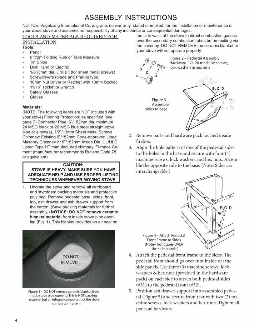
1. Uncrate the stove and remove all cardboard and styrofoam packing materials and protective poly bag. Remove pedestal base, sides, front, top, ash drawer and ash drawer support from the carton. (Save packing materials for further assembly.) NOTICE: DO NOT remove ceramic blanket material from inside stove pipe open-ing (Fig. 1). This blanket provides an air seal on
Figure 2 – Pedestal Assembly Hardware. 1/4-20 machine screws, lock washers & hex nuts
Figure 3 – Assemble
sides to base
Figure 4 – Attach Pedestal Front Frame to Sides.
(Note– front goes OVER the side panels.)
Figure 1 – DO NOT remove ceramic blanket from inside stove pipe opening. This is NOT packing material but an integral component of the stove
combustion system.
DO NOT REMOVE!
NOTICE: Vogelzang International Corp. grants no warranty, stated or implied, for the installation or maintenance of your wood stove and assumes no responsibility of any incidental or consequential damages.
the side walls of the stove to direct combustion gasses over the secondary combustion tubes before exiting via the chimney. DO NOT REMOVE the ceramic blanket or your stove will not operate properly.
2. Remove parts and hardware pack located inside firebox.
3. Align the hole pattern of one of the pedestal sides to the holes in the base and secure with four (4) machine screws, lock washers and hex nuts. Assem-ble the opposite side to the base. (Note: Sides are interchangeable.)
4. Attach the pedestal front frame to the sides. The pedestal front should go over (not inside of) the side panels. Use three (3) machine screws, lock-washers & hex nuts (provided in the hardware pack) on each side to attach both pedestal sides (#31) to the pedestal front (#32).
5. Position ash drawer support into assembled pedes-tal (Figure 5) and secure from rear with two (2) ma-chine screws, lock washers and hex nuts. Tighten all pedestal hardware.
5
ASSEMBLY INSTRUCTIONS
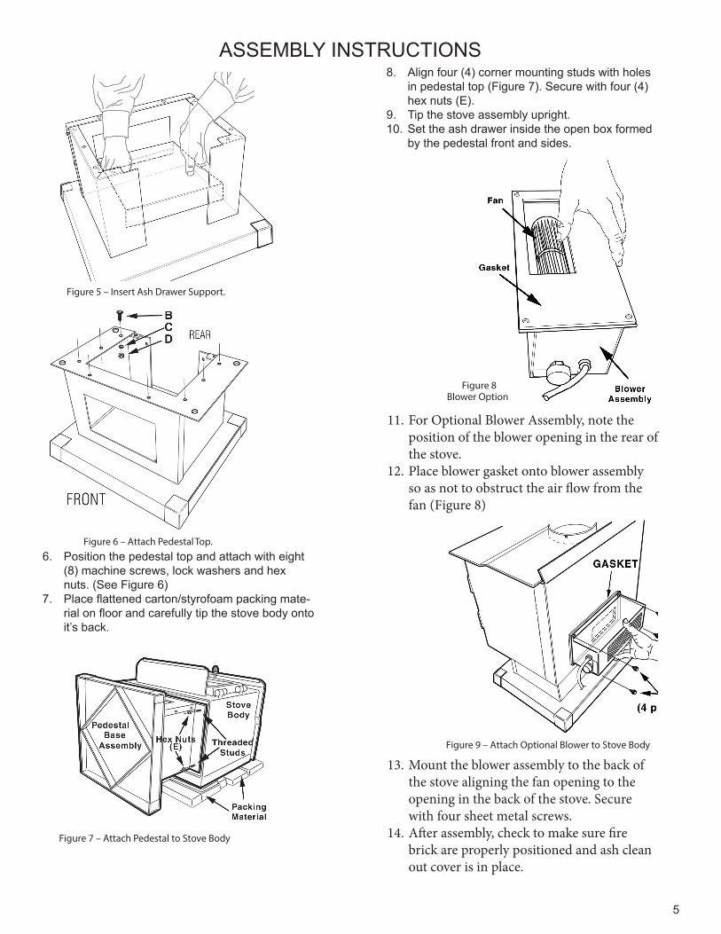
6. Position the pedestal top and attach with eight (8) machine screws, lock washers and hex nuts. (See Figure 6)
7. Place flattened carton/styrofoam packing mate-rial on floor and carefully tip the stove body onto it’s back.
Figure 6 – Attach Pedestal Top.
Figure 5 – Insert Ash Drawer Support.
Figure 7 – Attach Pedestal to Stove Body
Figure 8Blower Option
Figure 9 – Attach Optional Blower to Stove Body
8. Align four (4) corner mounting studs with holes in pedestal top (Figure 7). Secure with four (4) hex nuts (E).
9. Tip the stove assembly upright.10. Set the ash drawer inside the open box formed
by the pedestal front and sides.
11. For Optional Blower Assembly, note the position of the blower opening in the rear of the stove.
12. Place blower gasket onto blower assembly so as not to obstruct the air flow from the fan (Figure 8)
13. Mount the blower assembly to the back of the stove aligning the fan opening to the opening in the back of the stove. Secure with four sheet metal screws.
14. After assembly, check to make sure fire brick are properly positioned and ash clean out cover is in place.
6
LOCATING STOVE
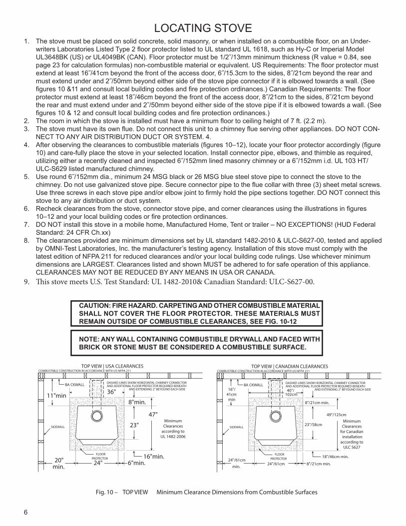
Fig. 10 – TOP VIEW Minimum Clearance Dimensions from Combustible Surfaces
FLOORPROTECTOR
DASHED LINES SHOW HORIZONTAL CHIMNEY CONNECTORAND ADDITIONAL FLOOR PROTECTOR REQUIRED BENEATH AND EXTENDING 2” BEYOUND EACH SIDE
COMBUSTIBLE CONSTRUCTION IN ACCORDANCE WITH US NFPA 211
BA CKWALL
SIDEWALL
8"min.
23"
47"
16"min.6"min.24" 20"
min.
11"min
TOP VIEW | USA CLEARANCES
36"
MinimumClearances
according toUL 1482-2006
FLOORPROTECTOR
DASHED LINES SHOW HORIZONTAL CHIMNEY CONNECTORAND ADDITIONAL FLOOR PROTECTOR REQUIRED BENEATH
AND EXTENDING 2” BEYOUND EACH SIDE
COMBUSTIBLE CONSTRUCTION IN ACCORDANCE WITH US NFPA 211
BA CKWALL
SIDEWALL23"/58cm
49"/125cm
18"/46cm min.
8"/21cm min.
8"/21cm min.
24"/61cm 24"/61cm
min.
16"/41cmmin
TOP VIEW | CANADIAN CLEARANCES
40"/102cm
MinimumClearances
for Canadian installationaccording to
ULC S627
1. The stove must be placed on solid concrete, solid masonry, or when installed on a combustible floor, on an Under-writers Laboratories Listed Type 2 floor protector listed to UL standard UL 1618, such as Hy-C or Imperial Model UL3648BK (US) or UL4049BK (CAN). Floor protector must be 1/2˝/13mm minimum thickness (R value = 0.84, see page 23 for calculation formulas) non-combustible material or equivalent. US Requirements: The floor protector must extend at least 16˝/41cm beyond the front of the access door, 6˝/15.3cm to the sides, 8˝/21cm beyond the rear and must extend under and 2˝/50mm beyond either side of the stove pipe connector if it is elbowed towards a wall. (See figures 10 &11 and consult local building codes and fire protection ordinances.) Canadian Requirements: The floor protector must extend at least 18˝/46cm beyond the front of the access door, 8˝/21cm to the sides, 8˝/21cm beyond the rear and must extend under and 2˝/50mm beyond either side of the stove pipe if it is elbowed towards a wall. (See figures 10 & 12 and consult local building codes and fire protection ordinances.)
2. The room in which the stove is installed must have a minimum floor to ceiling height of 7 ft. (2.2 m).3. The stove must have its own flue. Do not connect this unit to a chimney flue serving other appliances. DO NOT CON-
NECT TO ANY AIR DISTRIBUTION DUCT OR SYSTEM. 4. 4. After observing the clearances to combustible materials (figures 10–12), locate your floor protector accordingly (figure
10) and care-fully place the stove in your selected location. Install connector pipe, elbows, and thimble as required, utilizing either a recently cleaned and inspected 6˝/152mm lined masonry chimney or a 6˝/152mm i.d. UL 103 HT/ULC-S629 listed manufactured chimney.
5. Use round 6˝/152mm dia., minimum 24 MSG black or 26 MSG blue steel stove pipe to connect the stove to the chimney. Do not use galvanized stove pipe. Secure connector pipe to the flue collar with three (3) sheet metal screws. Use three screws in each stove pipe and/or elbow joint to firmly hold the pipe sections together. DO NOT connect this stove to any air distribution or duct system.
6. Recheck clearances from the stove, connector stove pipe, and corner clearances using the illustrations in figures 10–12 and your local building codes or fire protection ordinances.
7. DO NOT install this stove in a mobile home, Manufactured Home, Tent or trailer – NO EXCEPTIONS! (HUD Federal Standard: 24 CFR Ch.xx)
8. The clearances provided are minimum dimensions set by UL standard 1482-2010 & ULC-S627-00, tested and applied by OMNI-Test Laboratories, Inc. the manufacturer’s testing agency. Installation of this stove must comply with the latest edition of NFPA 211 for reduced clearances and/or your local building code rulings. Use whichever minimum dimensions are LARGEST. Clearances listed and shown MUST be adhered to for safe operation of this appliance. CLEARANCES MAY NOT BE REDUCED BY ANY MEANS IN USA OR CANADA.
9. This stove meets U.S. Test Standard: UL 1482-2010& Canadian Standard: ULC-S627-00.
CAUTION: FIRE HAZARD. CARPETING AND OTHER COMBUSTIBLE MATERIAL SHALL NOT COVER THE FLOOR PROTECTOR. THESE MATERIALS MUST REMAIN OUTSIDE OF COMBUSTIBLE CLEARANCES, SEE FIG. 10-12
NOTE: ANY WALL CONTAINING COMBUSTIBLE DRYWALL AND FACED WITH BRICK OR STONE MUST BE CONSIDERED A COMBUSTIBLE SURFACE.
7
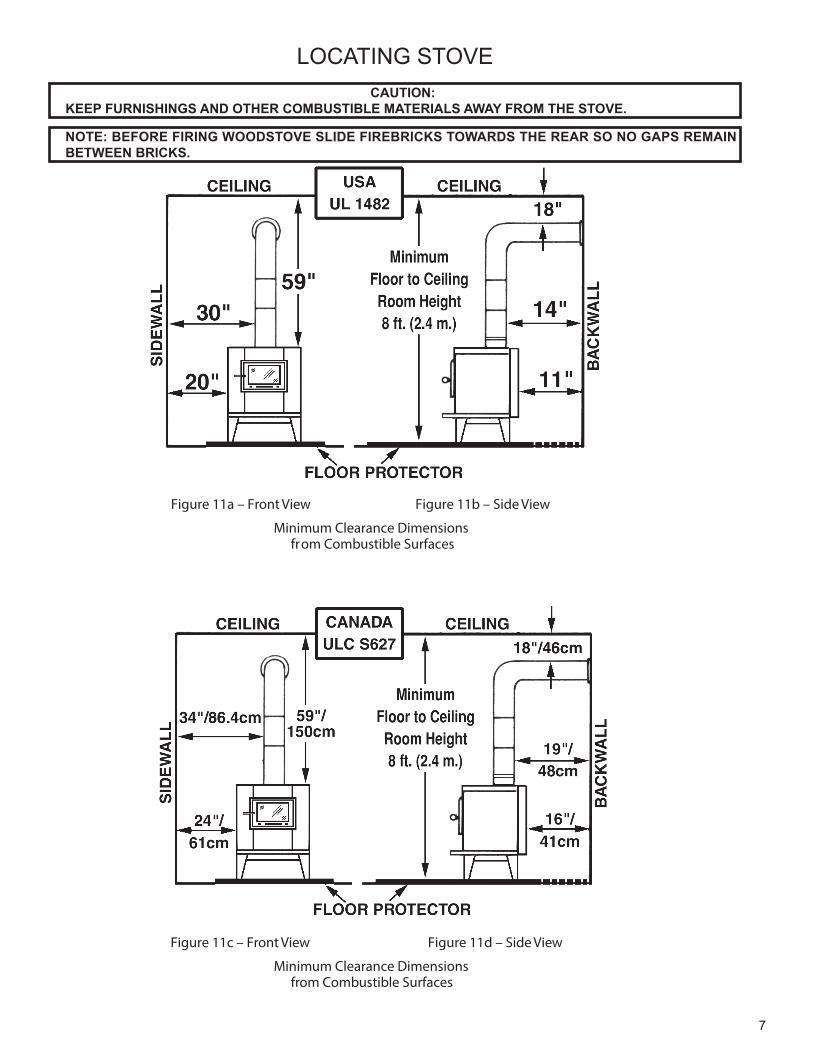
Figure 11a – Front View
Figure 11c – Front View
Figure 11b – Side View
Figure 11d – Side View
Minimum Clearance Dimensions from Combustible Surfaces
Minimum Clearance Dimensions from Combustible Surfaces
LOCATING STOVE CAUTION:
KEEP FURNISHINGS AND OTHER COMBUSTIBLE MATERIALS AWAY FROM THE STOVE.
NOTE: BEFORE FIRING WOODSTOVE SLIDE FIREBRICKS TOWARDS THE REAR SO NO GAPS REMAIN BETWEEN BRICKS.
8
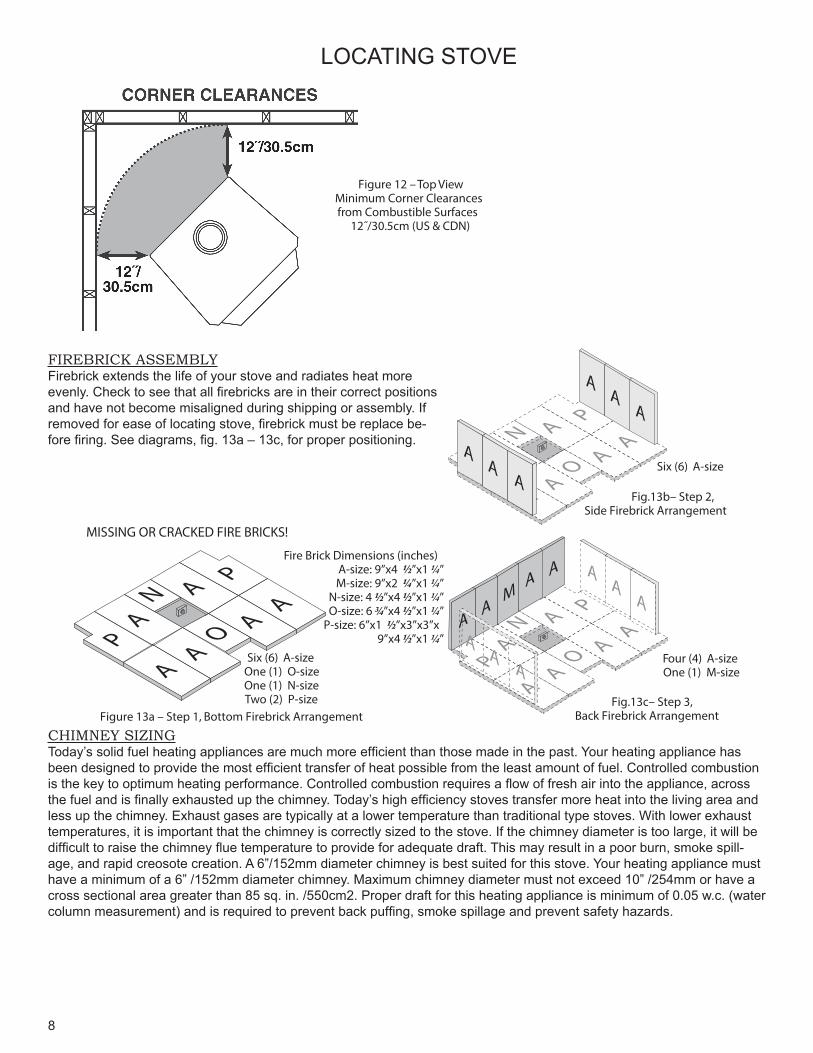
Figure 13a – Step 1, Bottom Firebrick Arrangement
Figure 12 – Top View Minimum Corner Clearances from Combustible Surfaces
12˝/30.5cm (US & CDN)
MISSING OR CRACKED FIRE BRICKS!
PA
AA
N
O
AP
AA
Six (6) A-sizeOne (1) O-sizeOne (1) N-sizeTwo (2) P-size
EA
AA
N
O
AP
AAA
AA
AA
A
Six (6) A-size
PA
AA
N
O
AP
AA
AA
A
AA
AM
AA
AA
Four (4) A-sizeOne (1) M-size
Fire Brick Dimensions (inches) A-size: 9”x4 ½”x1¼”M-size: 9”x2 ¼”x1¼”
N-size: 4½”x4½”x1¼”O-size: 6¾”x4½”x1¼”
P-size: 6”x1 ½”x3”x3”x 9”x4½”x1¼”
Fig.13b– Step 2, Side Firebrick Arrangement
Fig.13c– Step 3,Back Firebrick Arrangement
LOCATING STOVE
FIREBRICK ASSEMBLYFirebrick extends the life of your stove and radiates heat more evenly. Check to see that all firebricks are in their correct positions and have not become misaligned during shipping or assembly. If removed for ease of locating stove, firebrick must be replace be-fore firing. See diagrams, fig. 13a – 13c, for proper positioning.
CHIMNEY SIZINGToday’s solid fuel heating appliances are much more efficient than those made in the past. Your heating appliance has been designed to provide the most efficient transfer of heat possible from the least amount of fuel. Controlled combustion is the key to optimum heating performance. Controlled combustion requires a flow of fresh air into the appliance, across the fuel and is finally exhausted up the chimney. Today’s high efficiency stoves transfer more heat into the living area and less up the chimney. Exhaust gases are typically at a lower temperature than traditional type stoves. With lower exhaust temperatures, it is important that the chimney is correctly sized to the stove. If the chimney diameter is too large, it will be difficult to raise the chimney flue temperature to provide for adequate draft. This may result in a poor burn, smoke spill-age, and rapid creosote creation. A 6”/152mm diameter chimney is best suited for this stove. Your heating appliance must have a minimum of a 6” /152mm diameter chimney. Maximum chimney diameter must not exceed 10” /254mm or have a cross sectional area greater than 85 sq. in. /550cm2. Proper draft for this heating appliance is minimum of 0.05 w.c. (water column measurement) and is required to prevent back puffing, smoke spillage and prevent safety hazards.
9
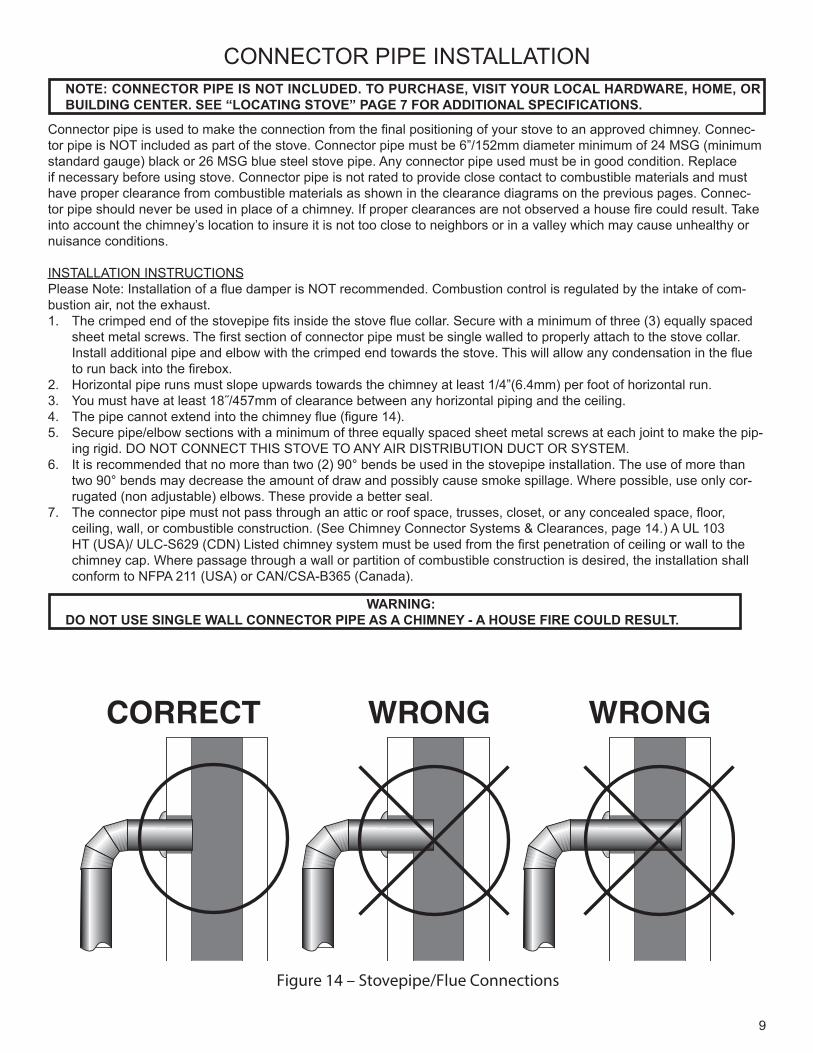
Figure 14 – Stovepipe/Flue Connections
CONNECTOR PIPE INSTALLATIONNOTE: CONNECTOR PIPE IS NOT INCLUDED. TO PURCHASE, VISIT YOUR LOCAL HARDWARE, HOME, OR BUILDING CENTER. SEE “LOCATING STOVE” PAGE 7 FOR ADDITIONAL SPECIFICATIONS.
WARNING: DO NOT USE SINGLE WALL CONNECTOR PIPE AS A CHIMNEY - A HOUSE FIRE COULD RESULT.
Connector pipe is used to make the connection from the final positioning of your stove to an approved chimney. Connec-tor pipe is NOT included as part of the stove. Connector pipe must be 6”/152mm diameter minimum of 24 MSG (minimum standard gauge) black or 26 MSG blue steel stove pipe. Any connector pipe used must be in good condition. Replace if necessary before using stove. Connector pipe is not rated to provide close contact to combustible materials and must have proper clearance from combustible materials as shown in the clearance diagrams on the previous pages. Connec-tor pipe should never be used in place of a chimney. If proper clearances are not observed a house fire could result. Take into account the chimney’s location to insure it is not too close to neighbors or in a valley which may cause unhealthy or nuisance conditions.
INSTALLATION INSTRUCTIONSPlease Note: Installation of a flue damper is NOT recommended. Combustion control is regulated by the intake of com-bustion air, not the exhaust. 1. The crimped end of the stovepipe fits inside the stove flue collar. Secure with a minimum of three (3) equally spaced
sheet metal screws. The first section of connector pipe must be single walled to properly attach to the stove collar. Install additional pipe and elbow with the crimped end towards the stove. This will allow any condensation in the flue to run back into the firebox.
2. Horizontal pipe runs must slope upwards towards the chimney at least 1/4”(6.4mm) per foot of horizontal run. 3. You must have at least 18˝/457mm of clearance between any horizontal piping and the ceiling.4. The pipe cannot extend into the chimney flue (figure 14).5. Secure pipe/elbow sections with a minimum of three equally spaced sheet metal screws at each joint to make the pip-
ing rigid. DO NOT CONNECT THIS STOVE TO ANY AIR DISTRIBUTION DUCT OR SYSTEM.6. It is recommended that no more than two (2) 90° bends be used in the stovepipe installation. The use of more than
two 90° bends may decrease the amount of draw and possibly cause smoke spillage. Where possible, use only cor-rugated (non adjustable) elbows. These provide a better seal.
7. The connector pipe must not pass through an attic or roof space, trusses, closet, or any concealed space, floor, ceiling, wall, or combustible construction. (See Chimney Connector Systems & Clearances, page 14.) A UL 103 HT (USA)/ ULC-S629 (CDN) Listed chimney system must be used from the first penetration of ceiling or wall to the chimney cap. Where passage through a wall or partition of combustible construction is desired, the installation shall conform to NFPA 211 (USA) or CAN/CSA-B365 (Canada).
10
CHIMNEY CONNECTIONSThe stove must be connected to either a lined masonry or manufactured metal chimney built and tested to the speci-fications listed on the previous pages. Chimneys perform two functions: 1. As a means of exhausting smoke and flue gases which
are the result of fuel combustion.2. The chimney (only) provides “draft” which allows oxy-
gen to be continuously introduced into the appliance, so that proper combustion is possible. This stove relies on natural draft to operate.
NOTICE: Always provide a source of fresh air into the room where the stove is located. Failure to do so may result in air starvation of other fuel burning appliances and the possible development of hazardous condi-tions.
A stove DOES NOT create draft. Draft is provided by the chimney. To achieve proper draft your chimney must meet the four minimum height requirements detailed in figures 16–18. If these minimum requirements are not met your stove will not operate properly. A minimum of 0.05 w.c. (measured in water column) is required for proper drafting to prevent back puffing, smoke spillage, and to maximize performance. (Gauges to measure draft are readily avail-able at stove stores and are economical to rent or pur-chase.) Factors such as wind, barometric pressure, trees, terrain and chimney temperature can have an adverse ef-fect on the draft. The manufacturer cannot be held respon-sible for external factors leading to less than optimal draft-ing. Should you have a problem with inadequate draft, you should contact a licensed heating and cooling contractor for assistance in solving the problem. For a more in-depth explanation see Chimney Draft on page 17.
IMPORTANT INSTALLATION POINTS1. Size chimney flue to stove collar. This stove requires a
minimum of a 6”/152mm diameter flue. 2. Never connect this unit to a chimney serving another
appliance.3. The chimney must meet all minimum height require-
ments.4. Never use a chimney to ventilate a cellar or basement.5. Contact your local building authority for approved
methods of installation and any necessary permits and/or inspections.
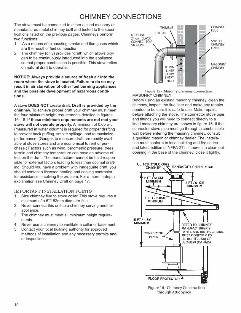
Figure 15 - Masonry Chimney Connection
CHIMNEYFLUE
5/8" TILECHIMNEYLINER
MASONRYCHIMNEY
THIMBLE
COLLAR6˝ ROUND24 ga . BLACKCONNEC TO RSTOVEPIPE
8˝ MIN.LINER
BELOWENTRY
HOLE
Figure 16 - Chimney Construction through Attic Space
MASONRY CHIMNEYBefore using an existing masonry chimney, clean the chimney, inspect the flue liner and make any repairs needed to be sure it is safe to use. Make repairs before attaching the stove. The connector stove pipe and fittings you will need to connect directly to a lined masonry chimney are shown in figure 15. If the connector stove pipe must go through a combustible wall before entering the masonry chimney, consult a qualified mason or chimney dealer. The installa-tion must conform to local building and fire codes and latest edition of NFPA 211. If there is a clean out opening in the base of the chimney, close it tightly.
11
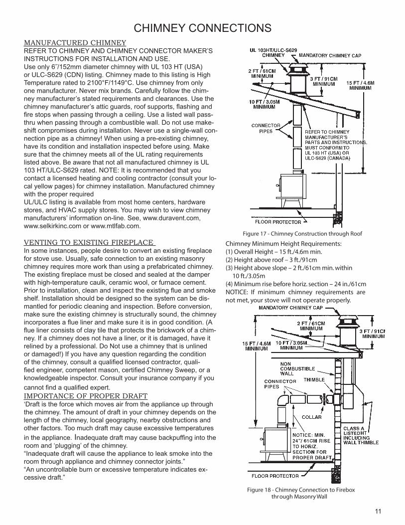
Figure 17 - Chimney Construction through Roof
Figure 18 - Chimney Connection to Firebox through Masonry Wall
Chimney Minimum Height Requirements:(1) Overall Height – 15 ft./4.6m min.(2) Height above roof – 3 ft./91cm(3) Height above slope – 2 ft./61cm min. within 10 ft./3.05m(4) Minimum rise before horiz. section – 24 in./61cmNOTICE: If minimum chimney requirements are not met, your stove will not operate properly.
CHIMNEY CONNECTIONSMANUFACTURED CHIMNEYREFER TO CHIMNEY AND CHIMNEY CONNECTOR MAKER’S INSTRUCTIONS FOR INSTALLATION AND USE.Use only 6˝/152mm diameter chimney with UL 103 HT (USA)or ULC-S629 (CDN) listing. Chimney made to this listing is High Temperature rated to 2100°F/1149°C. Use chimney from only one manufacturer. Never mix brands. Carefully follow the chim-ney manufacturer’s stated requirements and clearances. Use the chimney manufacturer’s attic guards, roof supports, flashing and fire stops when passing through a ceiling. Use a listed wall pass-thru when passing through a combustible wall. Do not use make-shift compromises during installation. Never use a single-wall con-nection pipe as a chimney! When using a pre-existing chimney, have its condition and installation inspected before using. Make sure that the chimney meets all of the UL rating requirements listed above. Be aware that not all manufactured chimney is UL 103 HT/ULC-S629 rated. NOTE: It is recommended that you contact a licensed heating and cooling contractor (consult your lo-cal yellow pages) for chimney installation. Manufactured chimney with the proper requiredUL/ULC listing is available from most home centers, hardware stores, and HVAC supply stores. You may wish to view chimney manufacturers’ information on-line. See, www.duravent.com, www.selkirkinc.com or www.mtlfab.com.
VENTING TO EXISTING FIREPLACE In some instances, people desire to convert an existing fireplace for stove use. Usually, safe connection to an existing masonry chimney requires more work than using a prefabricated chimney. The existing fireplace must be closed and sealed at the damper with high-temperature caulk, ceramic wool, or furnace cement. Prior to installation, clean and inspect the existing flue and smoke shelf. Installation should be designed so the system can be dis-mantled for periodic cleaning and inspection. Before conversion, make sure the existing chimney is structurally sound, the chimney incorporates a flue liner and make sure it is in good condition. (A flue liner consists of clay tile that protects the brickwork of a chim-ney. If a chimney does not have a liner, or it is damaged, have it relined by a professional. Do Not use a chimney that is unlined or damaged!) If you have any question regarding the condition of the chimney, consult a qualified licensed contractor, quali-fied engineer, competent mason, certified Chimney Sweep, or a knowledgeable inspector. Consult your insurance company if you cannot find a qualified expert.IMPORTANCE OF PROPER DRAFT‘Draft is the force which moves air from the appliance up through the chimney. The amount of draft in your chimney depends on the length of the chimney, local geography, nearby obstructions and other factors. Too much draft may cause excessive temperatures in the appliance. Inadequate draft may cause backpuffing into the room and ‘plugging’ of the chimney.“Inadequate draft will cause the appliance to leak smoke into the room through appliance and chimney connector joints.”“An uncontrollable burn or excessive temperature indicates ex-cessive draft.”
12
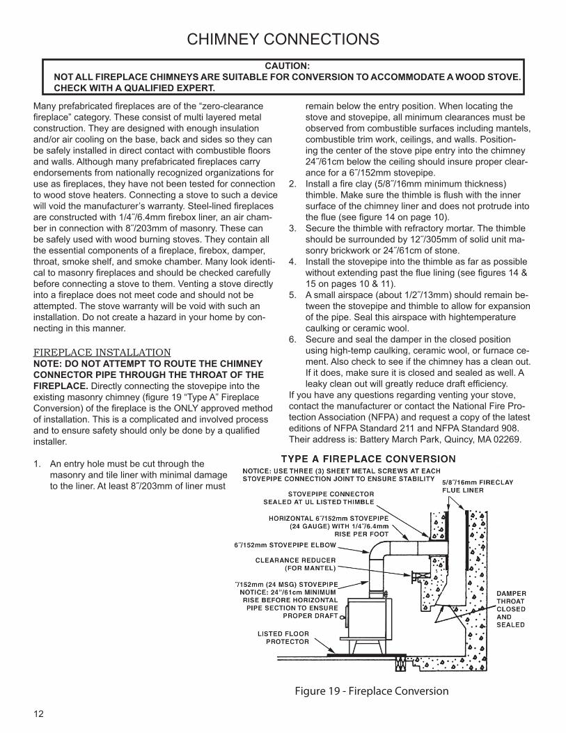
Figure 19 - Fireplace Conversion
CHIMNEY CONNECTIONSCAUTION:
NOT ALL FIREPLACE CHIMNEYS ARE SUITABLE FOR CONVERSION TO ACCOMMODATE A WOOD STOVE. CHECK WITH A QUALIFIED EXPERT.
Many prefabricated fireplaces are of the “zero-clearance fireplace” category. These consist of multi layered metal construction. They are designed with enough insulation and/or air cooling on the base, back and sides so they can be safely installed in direct contact with combustible floors and walls. Although many prefabricated fireplaces carry endorsements from nationally recognized organizations for use as fireplaces, they have not been tested for connection to wood stove heaters. Connecting a stove to such a device will void the manufacturer’s warranty. Steel-lined fireplaces are constructed with 1/4˝/6.4mm firebox liner, an air cham-ber in connection with 8˝/203mm of masonry. These can be safely used with wood burning stoves. They contain all the essential components of a fireplace, firebox, damper, throat, smoke shelf, and smoke chamber. Many look identi-cal to masonry fireplaces and should be checked carefullybefore connecting a stove to them. Venting a stove directly into a fireplace does not meet code and should not be attempted. The stove warranty will be void with such an installation. Do not create a hazard in your home by con-necting in this manner.
FIREPLACE INSTALLATIONNOTE: DO NOT ATTEMPT TO ROUTE THE CHIMNEY CONNECTOR PIPE THROUGH THE THROAT OF THE FIREPLACE. Directly connecting the stovepipe into the existing masonry chimney (figure 19 “Type A” Fireplace Conversion) of the fireplace is the ONLY approved method of installation. This is a complicated and involved process and to ensure safety should only be done by a qualified installer.
1. An entry hole must be cut through the masonry and tile liner with minimal damage to the liner. At least 8˝/203mm of liner must
remain below the entry position. When locating the stove and stovepipe, all minimum clearances must be observed from combustible surfaces including mantels, combustible trim work, ceilings, and walls. Position-ing the center of the stove pipe entry into the chimney 24˝/61cm below the ceiling should insure proper clear-ance for a 6˝/152mm stovepipe.
2. Install a fire clay (5/8˝/16mm minimum thickness) thimble. Make sure the thimble is flush with the inner surface of the chimney liner and does not protrude into the flue (see figure 14 on page 10).
3. Secure the thimble with refractory mortar. The thimble should be surrounded by 12˝/305mm of solid unit ma-sonry brickwork or 24˝/61cm of stone.
4. Install the stovepipe into the thimble as far as possible without extending past the flue lining (see figures 14 & 15 on pages 10 & 11).
5. A small airspace (about 1/2˝/13mm) should remain be-tween the stovepipe and thimble to allow for expansion of the pipe. Seal this airspace with hightemperature caulking or ceramic wool.
6. Secure and seal the damper in the closed position using high-temp caulking, ceramic wool, or furnace ce-ment. Also check to see if the chimney has a clean out. If it does, make sure it is closed and sealed as well. A leaky clean out will greatly reduce draft efficiency.
If you have any questions regarding venting your stove, contact the manufacturer or contact the National Fire Pro-tection Association (NFPA) and request a copy of the latest editions of NFPA Standard 211 and NFPA Standard 908. Their address is: Battery March Park, Quincy, MA 02269.
13
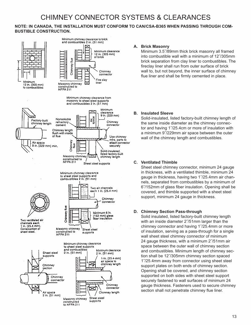
CHIMNEY CONNECTOR SYSTEMS & CLEARANCESNOTE: IN CANADA, THE INSTALLATION MUST CONFORM TO CAN/CSA-B365 WHEN PASSING THROUGH COM-BUSTIBLE CONSTRUCTION.
A. Brick Masonry Minimum 3.5˝/89mm thick brick masonry all framed
into combustible wall with a minimum of 12˝/305mm brick separation from clay liner to combustibles. The fireclay liner shall run from outer surface of brick wall to, but not beyond, the inner surface of chimney flue liner and shall be firmly cemented in place.
B. Insulated Sleeve Solid-insulated, listed factory-built chimney length of
the same inside diameter as the chimney connec-tor and having 1˝/25.4cm or more of insulation with a minimum 9˝/229mm air space between the outer wall of the chimney length and combustibles.
C. Ventilated Thimble Sheet steel chimney connector, minimum 24 gauge
in thickness, with a ventilated thimble, minimum 24 gauge in thickness, having two 1˝/25.4mm air chan-nels, separated from combustibles by a minimum of 6˝/152mm of glass fiber insulation. Opening shall be covered, and thimble supported with a sheet steel support, minimum 24 gauge in thickness.
D. Chimney Section Pass-through Solid insulated, listed factory-built chimney length
with an inside diameter 2˝/51mm larger than the chimney connector and having 1˝/25.4mm or more of insulation, serving as a pass-through for a single wall sheet steel chimney connector of minimum 24 gauge thickness, with a minimum 2˝/51mm air space between the outer wall of chimney section and combustibles. Minimum length of chimney sec-tion shall be 12˝/305mm chimney section spaced 1˝/25.4mm away from connector using sheet steel support plates on both ends of chimney section. Opening shall be covered, and chimney section supported on both sides with sheet steel support securely fastened to wall surfaces of minimum 24 gauge thickness. Fasteners used to secure chimney section shall not penetrate chimney flue liner.
14
OPERATING INSTRUCTIONSCAUTION: HOUSE FIRE HAZARDS
• DO NOT STORE WOOD ON FLOOR PROTECTOR, UNDERNEATH STOVEPIPE, OR ANYWHERE WITHIN MINIMUM CLEARANCES FROM COMBUSTIBLE SURFACES SPECIFIED FOR THIS STOVE.
• OVER FIRING MAY CAUSE A HOUSE FIRE. YOU ARE OVER FIRING IF A UNIT OR CHIMNEY CONNECTOR GLOWS RED.
WARNING: EXPLOSION HAZARD• DO NOT USE CHEMICALS OR FLUIDS TO START THE FIRE.• NEVER USE CHEMICALS, GASOLINE, GASOLINE-TYPE LANTERN FUEL, KEROSENE, CHARCOAL
LIGHTER FLUID, OR SIMILAR FLAMMABLE LIQUIDS TO START OR “FRESHEN- UP” A FIRE IN THE STOVE.• KEEP ALL FLAMMABLE LIQUIDS, ESPECIALLY GASOLINE, OUT OF THE VICINITY OF THE STOVE —
WHETHER IN USE OR IN STORAGE.
OPERATING SAFETY PRECAUTIONS1. NEVER OVER FIRE THIS STOVE BY BUILDING EXCESSIVELY HOT FIRES AS A HOUSE/ BUILDING FIRE MAY
RESULT. YOU ARE OVER FIRING THE STOVE IF UNIT OR STOVEPIPE BEGINS TO GLOW OR TURN RED.2. NEVER BUILD EXTREMELY LARGE FIRES IN THIS TYPE OF STOVE AS DAMAGE TO THE STOVE OR SMOKE
LEAKAGE MAY RESULT3. ON MODELS WITH GLASS DOOR, DO NOT BUILD FIRE TOO CLOSE TO GLASS.4. UNIT IS HOT WHILE IN OPERATION. KEEP CHILDREN, CLOTHING, AND FURNITURE AWAY. CONTACT MAY
CAUSE SKIN BURNS. DO NOT TOUCH THE STOVE AFTER FIRING UNTIL IT HAS COOLED.5. PROVIDE AIR INTO THE ROOM FOR PROPER COMBUSTION.6. INSPECT STOVEPIPE EVERY 60 DAYS. REPLACE IMMEDIATELY IF STOVEPIPE IS RUSTING OR LEAKING
SMOKE INTO THE ROOM. 7. ATTEMPTS TO ACHIEVE HEAT OUTPUT RATES THAT EXCEED HEATER DESIGN SPECIFICATIONS CAN RE-
SULT IN PERMANENT DAMAGE TO THE HEATER.
THIS STOVE IS DESIGNED TO BURN NATURAL WOOD FUEL ONLY!Hardwood, 18˝ to 20˝ / 45cm to 50cm should be air dried (seasoned), for a minimum of 6 months. Logs grater than 6˝/152mm in diameter should be split. Wood should be stored in a dry, well ventilated area. The humidity content for us-able firewood must be less than 20% of the weight of the log.This heater is designed to burn wood only. Higher efficien-cies and lower emissions generally result when burning air dried seasoned hardwoods, as compared to softwoods or to green or freshly cut hardwoods. Attempts to use wet or unseasoned wood will cause:- ignition problems - rapid creosote build-up resulting in chimney fire- incomplete combustion - low heat yield- blackened glass
DO NOT BURN:1. Garbage;2. Lawn clippings or yard waste;3. Materials containing rubber, including tires;4. Materials containing plastic;5. Waste petroleum products, paints or paint thinners, or
asphalt products;6. Materials containing asbestos;7. Construction or demolition debris;8. Railroad ties or pressure-treated wood;9. Manure or animal remains;
10. Salt water driftwood or other previously salt water satu-rated materials;
11. Unseasoned wood; or12. Paper products, cardboard, plywood, or particleboard.
The prohibition against burning these materials does not prohibit the use of fire starters made from paper, cardboard, saw dust, wax and similar substances for the purpose of starting a fire in an affected wood heater.
Burning these materials may result in release of toxic fumes or render the heater ineffective and cause smoke.Dead wood lying on the forest floor should be considered wet, and requires full seasoning time. Standing dead wood can usually be considered to be about 2/3 seasoned. Splitting and stacking wood before it is stored accelerates drying time. Storing wood on an elevated surface from the ground and under a cover or covered area from rain or snow also acceler-ates drying time. A good indicator if wood is ready to burn is to check the piece ends. If there are cracks radiating in all directions from the center then the wood should be dry enough to burn. If your wood sizzles in the fire, even though the surface is dry, it may not be fully cured, and should be seasoned longer
15
OPERATING INSTRUCTIONS
NOTICE: USE SOLID WOOD MATERIALS ONLY. DO NOT BURN GARBAGE OR FLAMMABLE FLUIDS SUCH AS GASOLINE, NAPHTHA OR ENGINE OIL. DO NOT USE COAL. THIS STOVE IS NOT DESIGNED TO ACCOMMODATE THE AIR FLOW (DRAFT) NECESSARY TO PROPERLY BURN COAL OR COAL PRODUCTS. DO NOT ELEVATE FIRE OR USE GRATES OR ANDIRONS. BUILD FIRE DIRECTLY ON BOTTOM OF FIREBOX.
OPTIMAL FUEL CONSUMPTIONThis stove is designed to get the most efficient transfer of heat energy from the wood fuel and radiate it into your living en-vironment. The fire box introduces combustion air through three sources. (1) Immediately beneath the door opening below the window is a Lower Primary Air Orifice (LPAO). (2) The primary air inlet control brings air into the firebox and controls the rate of burn (and the amount of heat the stove radiates). (3) The secondary air tubes at the top of the firebox are designed to ignite the combustion gases (smoke) given off by the burning wood and increases the efficiency of the stove and reduces chimney emissions. Smoke given off by burning fuel consists of very small organic liquid droplets. If these droplets condense, they form a sticky tar-like substance called creosote. When operated properly, this stove is designed to burn these droplets. Burning these droplets releases heat that would otherwise be lost up the chimney as smoke. Following the instructions below will help you operate your stove properly to maximize the stove’s performance. Actual performance is dependent on chimney height, weather, log size, wood species and moisture content. Some experimenta-tion will initially be required to find that “sweet spot” where your stove performs best. The following will give you a starting point to find your optimum settings.
When first loading fuel set the primary air inlet control at the wide open position for at least 15–20 minutes. When the stove is working properly you should be able to observe secondary combustion flames above the fuel pieces in front of the secondary air tubes at the top of the firebox. These secondary flames should continue to burn after the primary air inlet is reset from wide open to the desired operating setting. If the flames do not continue to burn, open the air control to re-establish the secondary flames then slowly reset the air control to the desired setting. Initially it may take several attempts to figure your stove out. But once you find the operating “sweet spot” and the correct mix of procedures to get there, only minor adjustments will be necessary. The best indicator of a properly operating stove is to look for smoke coming out of the chimney. You may see steam emissions that will quickly dissipate. Smoke will thin but continue to drift without totally disappearing. If you do detect smoke emissions, open the air control a little bit, let the stove adjust for 10–15 minutes and re-check your chimney. Remember – visible smoke represents lost heat.NOTICE - INITIAL BURNS TO CURE PAINT BECAUSE OF THE HIGH OPERATING TEMPERATURES, THIS STOVE USES A SPECIAL HIGH-TEMP PAINT WHICH REQUIRES A SERIES OF BURNS TO CURE THE PAINT FOR DURABIL-ITY AND A LIFETIME OF SERVICE.Proper curing of the high-temp paint requires a series of three initial burns. The stove should be allowed to cool off be-tween each burn. The first two burns should be small fires and low temperatures (250°F/120°C) for a duration of20 minutes each. The third fire should be at a medium-high temperature (500 to 700°F/260 to 370°C) for twenty minutes. Provide adequate cross ventilation to clear any smoke or odor caused by initial firings.
TAMPER WARNINGThis wood heater has a manufacturer-set minimum low burn rate that must not be altered. It is against federal regula-tions to alter this setting or otherwise operate this wood heater in a manner inconsistent with operating instructions in this manual.
EFFICIENCIES Efficiencies can be based on either the lower heating value (LHV) or the higher heating value (HHV) of the fuel. The lower heating value is when water leaves the combustion process as a vapor, in the case of woodstoves the moisture in the wood being burned leaves the stove as a vapor. The higher heating value is when water leaves the combustion process completely condensed. In the case of woodstoves this would assume the exhaust gases are room temperature when leav-ing the system, and therefore calculations using this heating value consider the heat going up the chimney as lost energy. Therefore, efficiency calculated using the lower heating value of wood will be higher than efficiency calculated using the higher heating value. In the United States all woodstove efficiencies should be calculated using the higher heating value. The best way to achieve optimum efficiencies is to learn the burn characteristic of you appliance and burn well-seasoned wood. Higher burn rates are not always the best heating burn rates; after a good fire is established a lower burn rate may be a better option for efficient heating. A lower burn rate slows the flow of usable heat out of the home through the chim-ney, and it also consumes less wood.
16
OPERATING INSTRUCTIONSSTARTING A FIREDO NOT LEAVE STOVE UNATTENDED WITH DOOR OPEN!The top down method of fire building is recommended for this appliance. After making sure that the stove air intake con-trols are fully open (completely pull-out towards you), Place the largest pieces of wood on the bottom, laid in parallel and close together. Smaller pieces are placed in a second layer, crossways to the first. A third layer of still smaller pieces is laid crossways to the second, this time with some spaces between. Then a fourth layer of loose, small kindling and twisted newspaper sheets tops off the pile. Add large pieces of wood as the fire progresses being careful not to overload. (Do not fill firebox beyond firebrick area.) An ideal coal bed of 1 –2” should be established to achieve optimum performance. This unit is designed to function most effectively when air is allowed to circulate to all areas of the firebox. TIP: If ash or coals remain in the stove, make sure to clear them away from the Lower Primary Air Orifice (LPAO) and rake a slight (1-to-2 inch wide) trough down the center of the coal bed from front to back prior to loading the fuel. Once fuel has been loaded, close the door and leave the air inlet control fully open until fire is well established (at least 15–20 minutes) being careful not to overfire (if any of the exterior parts of the stove or chimney connections begin to glow you are overfiring the stove). Re-adjust the door air inlet control to desired burn rate. (If excessive smoke fills the firebox, open air inlet control slightly until flames resume and wood is sufficiently ignited.) The basic rule of thumb is “closed - low,” “half way open - medium” and “fully open - high.” NOTE: The four (4) inlet holes in the primary air inlet control slide are designed to remain partially open with slide in the closed position.
VISIBLE SMOKE The amount of visible smoke being produced can be an effective method of determining how efficiently the combustion process is taking place at the given settings. Visible smoke consist of unburned fuel and moisture leaving your stove. Learn to adjust the air settings of your specific unit to produce the smallest amount of visible smoke. Wood that has not been seasoned properly and has a high wood moisture content will produce excess visible smoke and burn poorly.
ADDING FUEL If the coal bed is not hot and glowing, rake the coals to the front of the stove, close the door and adjust the air inlet control to the wide open position. Let the coals reheat for 10–15 minutes. When hot and glowing, spread them out and place your next fuel load into the stove (make sure no coals or ashes block the LPAO). Leave the door air inlet control in the wide open position for 15–20 minutes. Fuel load size can vary but should be kept 1–2˝ (25mm-50mm) below the secondary air tubes. Also position the fuel to leave space so the air from the inlet can work down between the pieces of fuel. This reduces the time it takes for new fuel to burn properly. 1. When refueling, adjust air inlet control to the fully open position. When fire brightens, slowly and carefully open the
door. This procedure will prevent gases from igniting causing smoke and flame spillage.2. When adding fuel be careful not to hit, bump or damage the ceramic baffle board located at the top of the firebox.3. Add fuel being careful not to overload or over fire the stove.4. When adding fuel be careful not to smother the fire. Do not build fires against glass and make sure the coal bed does
not obstruct the air inlet. Do not load fuel to a height or in such a manner that it creates a hazard when opening the door.
5. Close the feed door and secure tightly. 6. Adjust the air inlet control as described above.7. Empty ashes regularly. Do not allow ashes to pile up (see Safety Instructions #14 on page 2.)8. Properly dispose of hot ashes (see Safety Instructions, item #14 on page 2.)9. Do not over fire the stove (over firing is when any part of the stove exterior or chimney connections glow).
OPERATIONAL TIPSOperational Tips for Good, Efficient, and Clean Combustion• Get the appliance hot and establish a good coal bed before adjusting to a low burn rate (this may take 30 minutes or
more depending on your wood)• Use smaller pieces of wood during start-up and a high burn rate to increase the stove temperature • Be considerate of the environment and only burn dry wood
CAUTION: A CHIMNEY FIRE MAY CAUSE IGNITION OF WALL STUDS OR RAFTERS WHICH WERE ASSUMED TO BE A SAFE DISTANCE FROM THE CHIMNEY. IF A CHIMNEY FIRE HAS OCCURRED, HAVE YOUR CHIMNEY INSPECTED BY
A QUALIFIED EXPERT BEFORE USING AGAIN.
17
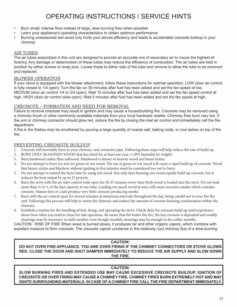
OPERATING INSTRUCTIONS / SERVICE HINTS
CAUTION: DO NOT OVER FIRE APPLIANCE. YOU ARE OVER FIRING IF THE CHIMNEY CONNECTORS OR STOVE GLOWS RED. CLOSE THE DOOR AND SHUT DAMPER IMMEDIATELY TO REDUCE THE AIR SUPPLY AND SLOW DOWN
THE FIRE.
CAUTION: SLOW BURNING FIRES AND EXTENDED USE MAY CAUSE EXCESSIVE CREOSOTE BUILDUP. IGNITION OF CREOSOTE OR OVER FIRING MAY CAUSE A CHIMNEY FIRE. CHIMNEY FIRES BURN EXTREMELY HOT AND MAY IGNITE SURROUNDING MATERIALS. IN CASE OF A CHIMNEY FIRE CALL THE FIRE DEPARTMENT IMMEDIATELY.
BLOWER OPERATIONIf your stove is equipped with the blower attachment, follow these instructions for optimal operation. LOW (door air control is fully closed to 1/4 open): Turn the fan on 30 minutes after fuel has been added and set the fan speed at low.MEDIUM (door air control 1/4 to 3/4 open): Wait 15 minutes after fuel has been added and set the fan speed control at high. HIGH (door air control wide open): Wait 5 minutes after fuel has been added and set the fan speed at high.
CREOSOTE – FORMATION AND NEED FOR REMOVALFailure to remove creosote may result in ignition and may cause a house/building fire. Creosote may be removed using a chimney brush or other commonly available materials from your local hardware retailer. Chimney fires burn very hot. If the unit or chimney connector should glow red, reduce the fire by closing the inlet air control and immediately call the fire department.A fire in the firebox may be smothered by pouring a large quantity of coarse salt, baking soda, or cool ashes on top of the fire.
PREVENTING CREOSOTE BUILDUP1. Creosote will inevitably form in your chimney and connector pipe. Following these steps will help reduce the rate of build up.2. BURN ONLY SEASONED WOOD that has dried for at least one year. (<20% humidity by weight)3. Burn hardwood rather than softwood. Hardwood is denser or heavier wood and burns hotter.4. Do not attempt to burn (or mix in) green or wet wood. The use of green or wet wood will cause a rapid build up of creosote. Wood
that hisses, sizzles and blackens without igniting in five minutes must be considered too wet to burn.5. Do not attempt to extend the burn time by using wet wood. Not only does burning wet wood rapidly build up creosote, but it
reduces the heat output by up to 25 percent.6. Burn the stove with the air inlet control wide open for 10-25 minutes every time fresh wood is loaded into the stove. Do not load
more than ¼ to ½ of the fuel capacity at one time. Loading too much wood at once will cause excessive smoke which contains creosote. Mature fires or coals produce very little creosote-producing smoke.
7. Burn with the air control open for several minutes at numerous intervals throughout the day, being careful not to over fire the unit. Following this process will help to warm the chimney and reduce the amount of creosote forming condensation within the chimney.
8. Establish a routine for the handling of fuel, firing, and operating the stove. Check daily for creosote build up until experience shows how often you need to clean for safe operation. Be aware that the hotter the fire, the less creosote is deposited and weekly cleanings may be necessary in mild weather even though monthly cleanings may be enough in the colder months.
CAUTION: RISK OF FIRE When wood is burned slowly, it produces tar and other organic vapors, which combine with expelled moisture to form creosote. The creosote vapors condense in the relatively cool chimney flue of a slow-burning
• Burn small, intense fires instead of large, slow burning fires when possible • Learn your appliance’s operating characteristics to obtain optimum performance • Burning unseasoned wet wood only hurts your stoves efficiency and leads to accelerated creosote buildup in your
chimney
AIR TUBESThe air tubes assembled in this unit are designed to provide an accurate mix of secondary air to insure the highest ef-ficiency. Any damage or deterioration of these tubes may reduce the efficiency of combustion. The air tubes are held in position by either screws or snap pins. Locate these to either side of the tube and remove to allow the tube to be removed and replaced.
18
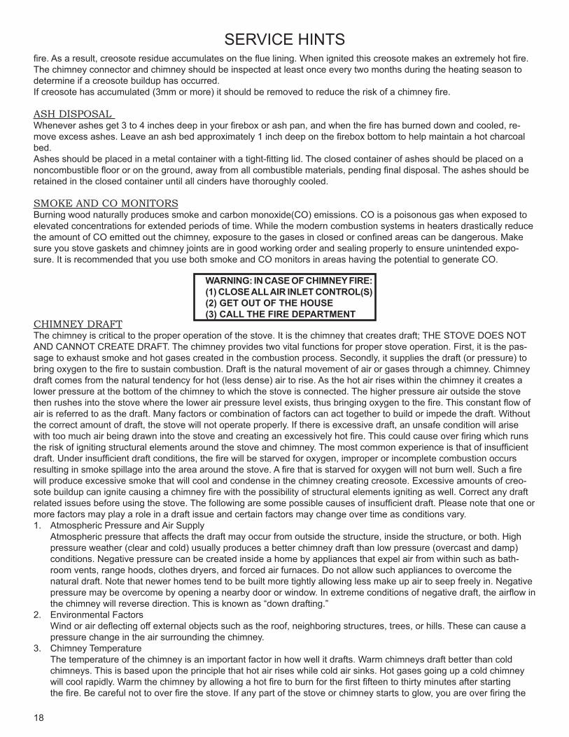
CHIMNEY DRAFTThe chimney is critical to the proper operation of the stove. It is the chimney that creates draft; THE STOVE DOES NOT AND CANNOT CREATE DRAFT. The chimney provides two vital functions for proper stove operation. First, it is the pas-sage to exhaust smoke and hot gases created in the combustion process. Secondly, it supplies the draft (or pressure) to bring oxygen to the fire to sustain combustion. Draft is the natural movement of air or gases through a chimney. Chimney draft comes from the natural tendency for hot (less dense) air to rise. As the hot air rises within the chimney it creates a lower pressure at the bottom of the chimney to which the stove is connected. The higher pressure air outside the stove then rushes into the stove where the lower air pressure level exists, thus bringing oxygen to the fire. This constant flow of air is referred to as the draft. Many factors or combination of factors can act together to build or impede the draft. Without the correct amount of draft, the stove will not operate properly. If there is excessive draft, an unsafe condition will arise with too much air being drawn into the stove and creating an excessively hot fire. This could cause over firing which runs the risk of igniting structural elements around the stove and chimney. The most common experience is that of insufficient draft. Under insufficient draft conditions, the fire will be starved for oxygen, improper or incomplete combustion occurs resulting in smoke spillage into the area around the stove. A fire that is starved for oxygen will not burn well. Such a fire will produce excessive smoke that will cool and condense in the chimney creating creosote. Excessive amounts of creo-sote buildup can ignite causing a chimney fire with the possibility of structural elements igniting as well. Correct any draft related issues before using the stove. The following are some possible causes of insufficient draft. Please note that one or more factors may play a role in a draft issue and certain factors may change over time as conditions vary. 1. Atmospheric Pressure and Air Supply Atmospheric pressure that affects the draft may occur from outside the structure, inside the structure, or both. High
pressure weather (clear and cold) usually produces a better chimney draft than low pressure (overcast and damp) conditions. Negative pressure can be created inside a home by appliances that expel air from within such as bath-room vents, range hoods, clothes dryers, and forced air furnaces. Do not allow such appliances to overcome the natural draft. Note that newer homes tend to be built more tightly allowing less make up air to seep freely in. Negative pressure may be overcome by opening a nearby door or window. In extreme conditions of negative draft, the airflow in the chimney will reverse direction. This is known as “down drafting.”
2. Environmental Factors Wind or air deflecting off external objects such as the roof, neighboring structures, trees, or hills. These can cause a
pressure change in the air surrounding the chimney. 3. Chimney Temperature The temperature of the chimney is an important factor in how well it drafts. Warm chimneys draft better than cold
chimneys. This is based upon the principle that hot air rises while cold air sinks. Hot gases going up a cold chimney will cool rapidly. Warm the chimney by allowing a hot fire to burn for the first fifteen to thirty minutes after starting the fire. Be careful not to over fire the stove. If any part of the stove or chimney starts to glow, you are over firing the
WARNING: IN CASE OF CHIMNEY FIRE:(1) CLOSE ALL AIR INLET CONTROL(S)(2) GET OUT OF THE HOUSE(3) CALL THE FIRE DEPARTMENT
SERVICE HINTSfire. As a result, creosote residue accumulates on the flue lining. When ignited this creosote makes an extremely hot fire. The chimney connector and chimney should be inspected at least once every two months during the heating season to determine if a creosote buildup has occurred. If creosote has accumulated (3mm or more) it should be removed to reduce the risk of a chimney fire.
ASH DISPOSAL Whenever ashes get 3 to 4 inches deep in your firebox or ash pan, and when the fire has burned down and cooled, re-move excess ashes. Leave an ash bed approximately 1 inch deep on the firebox bottom to help maintain a hot charcoal bed.Ashes should be placed in a metal container with a tight-fitting lid. The closed container of ashes should be placed on a noncombustible floor or on the ground, away from all combustible materials, pending final disposal. The ashes should be retained in the closed container until all cinders have thoroughly cooled.
SMOKE AND CO MONITORSBurning wood naturally produces smoke and carbon monoxide(CO) emissions. CO is a poisonous gas when exposed to elevated concentrations for extended periods of time. While the modern combustion systems in heaters drastically reduce the amount of CO emitted out the chimney, exposure to the gases in closed or confined areas can be dangerous. Make sure you stove gaskets and chimney joints are in good working order and sealing properly to ensure unintended expo-sure. It is recommended that you use both smoke and CO monitors in areas having the potential to generate CO.
19
SERVICE HINTS
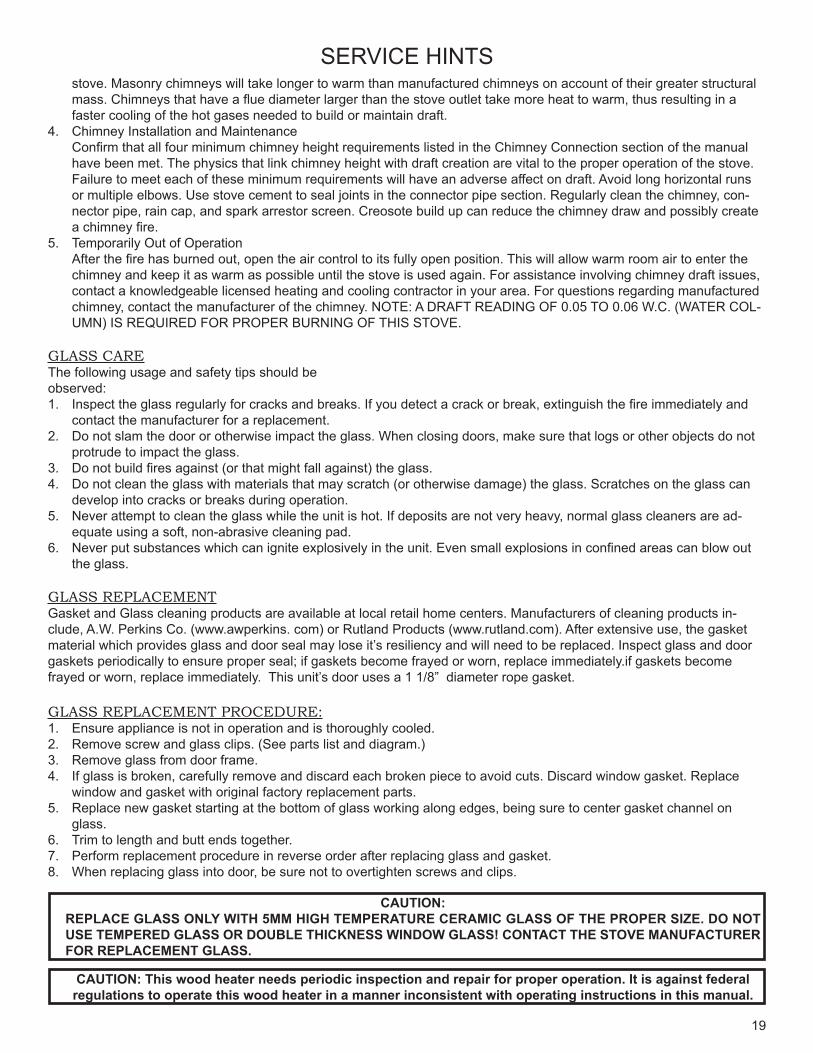
CAUTION: REPLACE GLASS ONLY WITH 5MM HIGH TEMPERATURE CERAMIC GLASS OF THE PROPER SIZE. DO NOT USE TEMPERED GLASS OR DOUBLE THICKNESS WINDOW GLASS! CONTACT THE STOVE MANUFACTURER FOR REPLACEMENT GLASS.
CAUTION: This wood heater needs periodic inspection and repair for proper operation. It is against federalregulations to operate this wood heater in a manner inconsistent with operating instructions in this manual.
stove. Masonry chimneys will take longer to warm than manufactured chimneys on account of their greater structural mass. Chimneys that have a flue diameter larger than the stove outlet take more heat to warm, thus resulting in a faster cooling of the hot gases needed to build or maintain draft.
4. Chimney Installation and Maintenance Confirm that all four minimum chimney height requirements listed in the Chimney Connection section of the manual
have been met. The physics that link chimney height with draft creation are vital to the proper operation of the stove. Failure to meet each of these minimum requirements will have an adverse affect on draft. Avoid long horizontal runs or multiple elbows. Use stove cement to seal joints in the connector pipe section. Regularly clean the chimney, con-nector pipe, rain cap, and spark arrestor screen. Creosote build up can reduce the chimney draw and possibly create a chimney fire.
5. Temporarily Out of Operation After the fire has burned out, open the air control to its fully open position. This will allow warm room air to enter the
chimney and keep it as warm as possible until the stove is used again. For assistance involving chimney draft issues, contact a knowledgeable licensed heating and cooling contractor in your area. For questions regarding manufactured chimney, contact the manufacturer of the chimney. NOTE: A DRAFT READING OF 0.05 TO 0.06 W.C. (WATER COL-UMN) IS REQUIRED FOR PROPER BURNING OF THIS STOVE.
GLASS CAREThe following usage and safety tips should beobserved:1. Inspect the glass regularly for cracks and breaks. If you detect a crack or break, extinguish the fire immediately and
contact the manufacturer for a replacement.2. Do not slam the door or otherwise impact the glass. When closing doors, make sure that logs or other objects do not
protrude to impact the glass.3. Do not build fires against (or that might fall against) the glass.4. Do not clean the glass with materials that may scratch (or otherwise damage) the glass. Scratches on the glass can
develop into cracks or breaks during operation.5. Never attempt to clean the glass while the unit is hot. If deposits are not very heavy, normal glass cleaners are ad-
equate using a soft, non-abrasive cleaning pad.6. Never put substances which can ignite explosively in the unit. Even small explosions in confined areas can blow out
the glass.
GLASS REPLACEMENTGasket and Glass cleaning products are available at local retail home centers. Manufacturers of cleaning products in-clude, A.W. Perkins Co. (www.awperkins. com) or Rutland Products (www.rutland.com). After extensive use, the gasket material which provides glass and door seal may lose it’s resiliency and will need to be replaced. Inspect glass and door gaskets periodically to ensure proper seal; if gaskets become frayed or worn, replace immediately.if gaskets become frayed or worn, replace immediately. This unit’s door uses a 1 1/8” diameter rope gasket.
GLASS REPLACEMENT PROCEDURE:1. Ensure appliance is not in operation and is thoroughly cooled.2. Remove screw and glass clips. (See parts list and diagram.)3. Remove glass from door frame.4. If glass is broken, carefully remove and discard each broken piece to avoid cuts. Discard window gasket. Replace
window and gasket with original factory replacement parts.5. Replace new gasket starting at the bottom of glass working along edges, being sure to center gasket channel on
glass.6. Trim to length and butt ends together.7. Perform replacement procedure in reverse order after replacing glass and gasket.8. When replacing glass into door, be sure not to overtighten screws and clips.
20
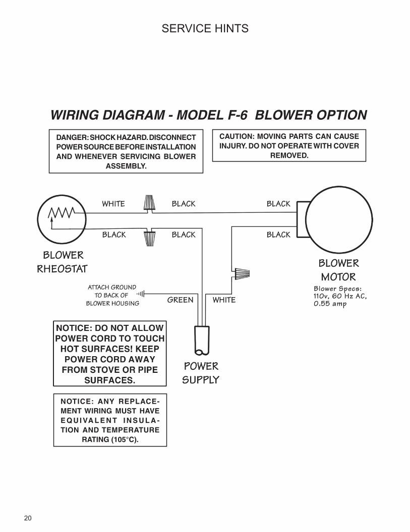
WIRING DIAGRAM - MODEL F-6 BLOWER OPTION
NOTICE: ANY REPLACE-MENT WIRING MUST HAVE E Q U I VA L E N T I N S U L A -TION AND TEMPERATURE
RATING (105°C).
CAUTION: MOVING PARTS CAN CAUSE INJURY. DO NOT OPERATE WITH COVER
REMOVED.
DANGER: SHOCK HAZARD. DISCONNECT POWER SOURCE BEFORE INSTALLATION AND WHENEVER SERVICING BLOWER
ASSEMBLY.
SERVICE HINTS
21
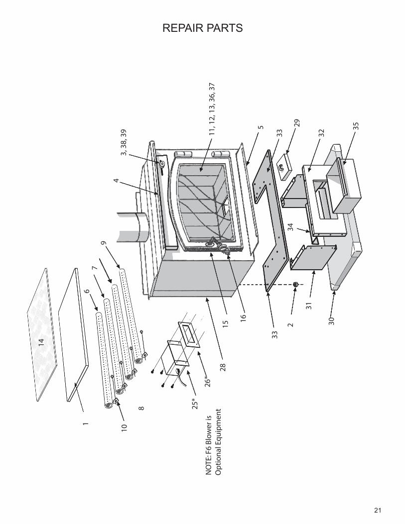
REPAIR PARTS
8
14
97
43,
38,
39 5
6
11, 1
2, 1
3, 3
6, 3
7
16
15
1
30
292
31
32
35
3433
33
28
25*
26*
10
NO
TE: F
6 Bl
ower
is
O
ptio
nal E
quip
men
t
22
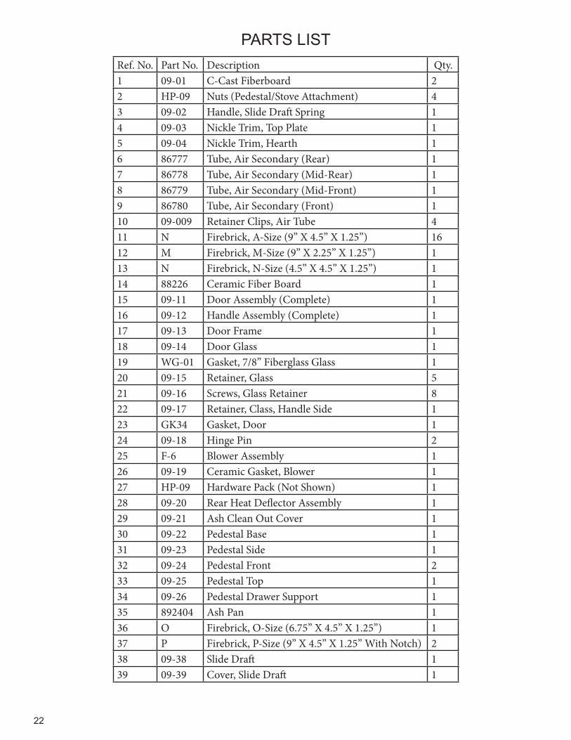
Ref. No. Part No. Description Qty.1 09-01 C-Cast Fiberboard 22 HP-09 Nuts (Pedestal/Stove Attachment) 43 09-02 Handle, Slide Draft Spring 14 09-03 Nickle Trim, Top Plate 15 09-04 Nickle Trim, Hearth 16 86777 Tube, Air Secondary (Rear) 17 86778 Tube, Air Secondary (Mid-Rear) 18 86779 Tube, Air Secondary (Mid-Front) 19 86780 Tube, Air Secondary (Front) 110 09-009 Retainer Clips, Air Tube 411 N Firebrick, A-Size (9” X 4.5” X 1.25”) 1612 M Firebrick, M-Size (9” X 2.25” X 1.25”) 113 N Firebrick, N-Size (4.5” X 4.5” X 1.25”) 114 88226 Ceramic Fiber Board 115 09-11 Door Assembly (Complete) 116 09-12 Handle Assembly (Complete) 117 09-13 Door Frame 118 09-14 Door Glass 119 WG-01 Gasket, 7/8” Fiberglass Glass 120 09-15 Retainer, Glass 521 09-16 Screws, Glass Retainer 822 09-17 Retainer, Class, Handle Side 123 GK34 Gasket, Door 124 09-18 Hinge Pin 225 F-6 Blower Assembly 126 09-19 Ceramic Gasket, Blower 127 HP-09 Hardware Pack (Not Shown) 128 09-20 Rear Heat Deflector Assembly 129 09-21 Ash Clean Out Cover 130 09-22 Pedestal Base 131 09-23 Pedestal Side 132 09-24 Pedestal Front 233 09-25 Pedestal Top 134 09-26 Pedestal Drawer Support 135 892404 Ash Pan 136 O Firebrick, O-Size (6.75” X 4.5” X 1.25”) 137 P Firebrick, P-Size (9” X 4.5” X 1.25” With Notch) 238 09-38 Slide Draft 139 09-39 Cover, Slide Draft 1
PARTS LIST
23
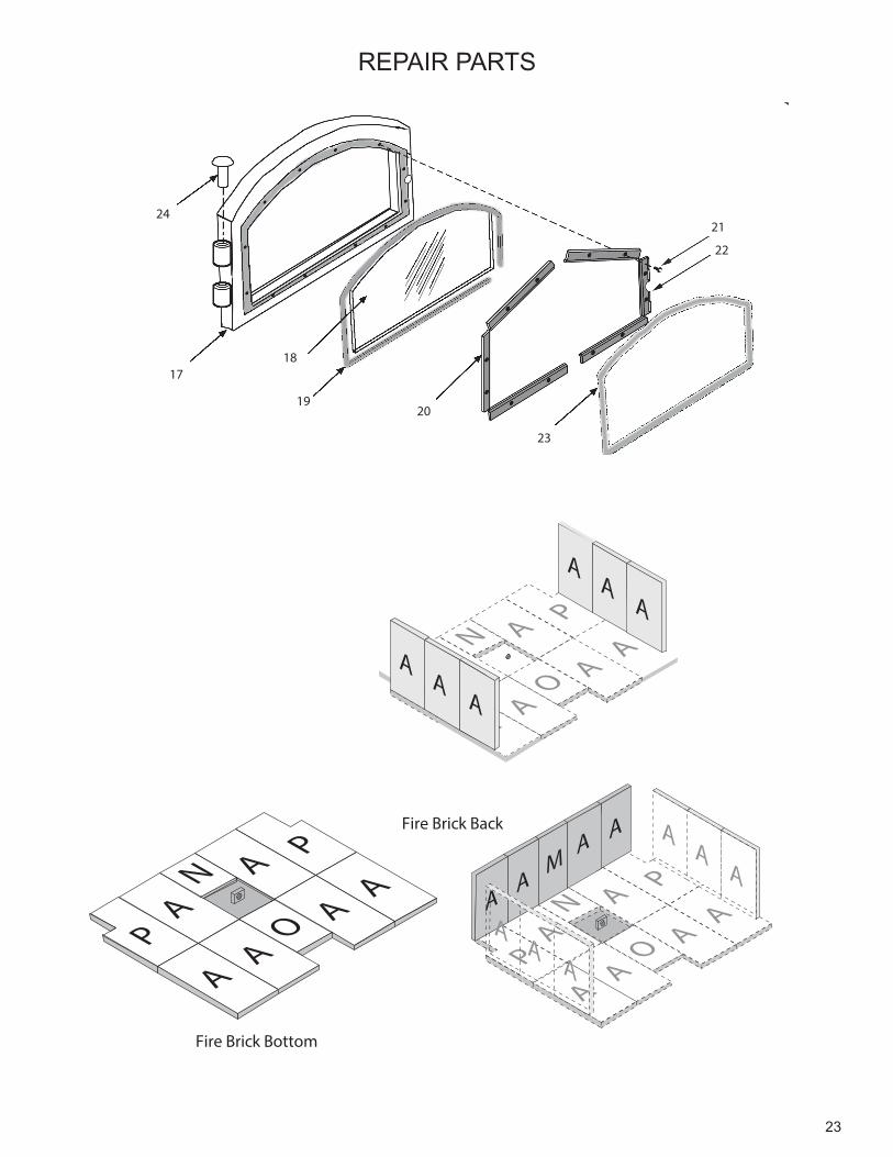
1718
1920
23
2421
22
23
Fire Brick Bottom
PA
AA
N
O
AP
AA
Fire Brick Sides
EA
AA
N
O
AP
AAA
AA
AA
A
PA
AA
N
O
AP
AA
AA
A
AA
AM
AA
AA
Fire Brick Back
REPAIR PARTS

24
NOTES

25
NOTES

26
NOTES
27
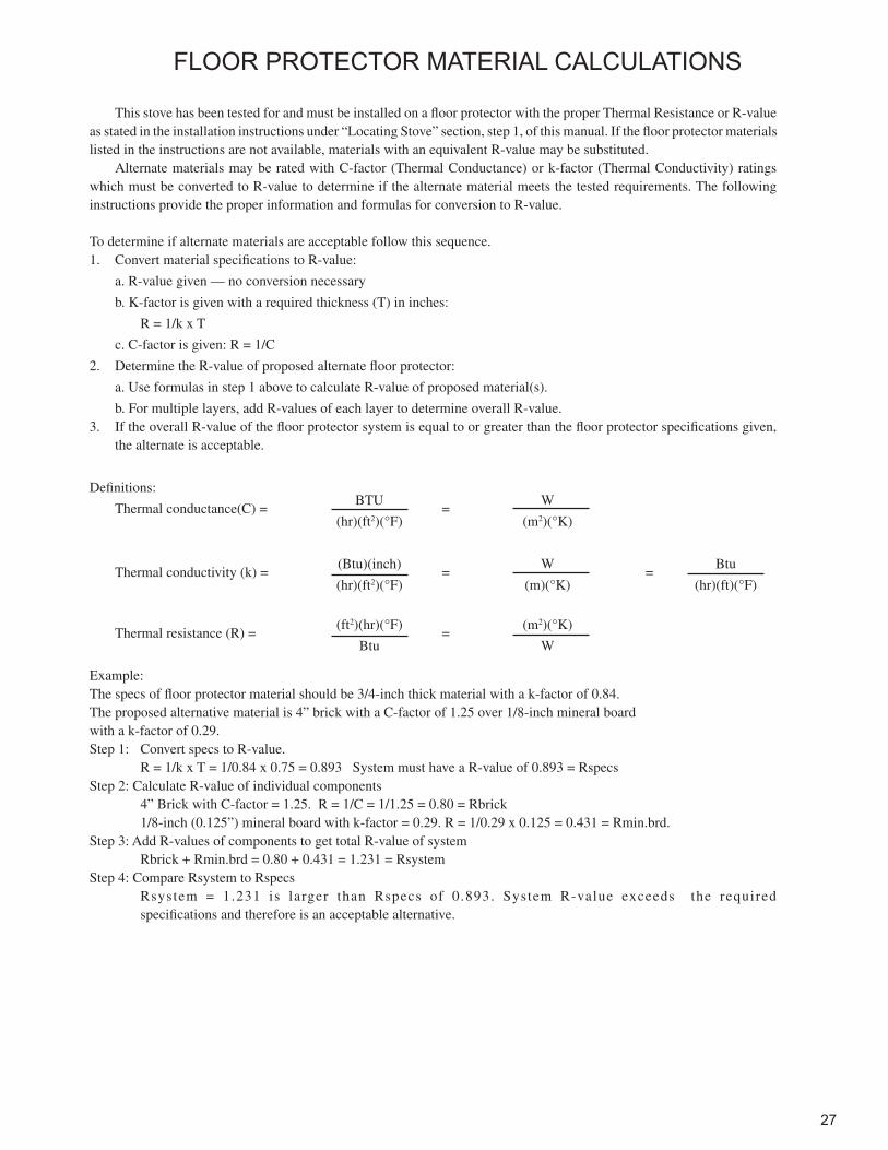
This stove has been tested for and must be installed on a floor protector with the proper Thermal Resistance or R-value as stated in the installation instructions under “Locating Stove” section, step 1, of this manual. If the floor protector materials listed in the instructions are not available, materials with an equivalent R-value may be substituted.
Alternate materials may be rated with C-factor (Thermal Conductance) or k-factor (Thermal Conductivity) ratings which must be converted to R-value to determine if the alternate material meets the tested requirements. The following instructions provide the proper information and formulas for conversion to R-value.
To determine if alternate materials are acceptable follow this sequence.1. Convert material specifications to R-value:
a. R-value given — no conversion necessary
b. K-factor is given with a required thickness (T) in inches:
R = 1/k x T
c. C-factor is given: R = 1/C
2. Determine the R-value of proposed alternate floor protector:
a. Use formulas in step 1 above to calculate R-value of proposed material(s).
b. For multiple layers, add R-values of each layer to determine overall R-value.3. If the overall R-value of the floor protector system is equal to or greater than the floor protector specifications given,
the alternate is acceptable.
Definitions:
Thermal conductance(C) = BTU
= W
(hr)(ft2)(°F) (m2)(°K)
Thermal conductivity (k) = (Btu)(inch)
= W
= Btu
(hr)(ft2)(°F) (m)(°K) (hr)(ft)(°F)
Thermal resistance (R) = (ft2)(hr)(°F)
= (m2)(°K)
Btu W
Example:The specs of floor protector material should be 3/4-inch thick material with a k-factor of 0.84.The proposed alternative material is 4” brick with a C-factor of 1.25 over 1/8-inch mineral board with a k-factor of 0.29.Step 1: Convert specs to R-value. R = 1/k x T = 1/0.84 x 0.75 = 0.893 System must have a R-value of 0.893 = RspecsStep 2: Calculate R-value of individual components 4” Brick with C-factor = 1.25. R = 1/C = 1/1.25 = 0.80 = Rbrick 1/8-inch (0.125”) mineral board with k-factor = 0.29. R = 1/0.29 x 0.125 = 0.431 = Rmin.brd.Step 3: Add R-values of components to get total R-value of system Rbrick + Rmin.brd = 0.80 + 0.431 = 1.231 = RsystemStep 4: Compare Rsystem to Rspecs Rsystem = 1.231 is larger than Rspecs of 0.893. System R-value exceeds the required specifications and therefore is an acceptable alternative.
FLOOR PROTECTOR MATERIAL CALCULATIONS
U. S. Stove Company227 Industrial Park RoadSouth Pittsburg, Tennessee 37380www.usstove.comPhone: 800-750-2723