the perfect fit - lund universitylup.lub.lu.se/student-papers/record/8875364/file/8875371.pdf ·...
TRANSCRIPT

gsgsgsgg
DIVISION OF PRODUCT DEVELOPMENT | DEPARTMENT OF DESIGN SCIENCES
FACULTY OF ENGINEERING LTH | LUND UNIVERSITY
2016
MASTER THESIS
Emelie Strömshed
The Perfect Fit Development process for the use of 3D technology in the
manufacturing of custom-made prosthetic arm sockets


The Perfect Fit
Development process for the use of 3D technology in the
manufacturing of custom-made prosthetic arm sockets
Emelie Strömshed

The Perfect Fit Development process for the use of 3D technology in the
manufacturing of custom-made prosthetic arm sockets
Copyright © 2016 Emelie Strömshed
Published by
Department of Design Sciences
Faculty of Engineering LTH, Lund University
P.O. Box 118, SE-221 00 Lund, Sweden
Subject: Technical Design (MMK920)
Division: Product Development
Supervisor: Olaf Diegel
Co-supervisor: Christian Antfolk
Examiner: Giorgos Nikoleris

i
Preface
This master thesis is the result of the final stage of my studies in Mechanical
Engineering with Industrial Design. The thesis has been conducted at the Division of
Product Development, the Faculty of Engineering at Lund University and in
collaboration with Aktiv Ortopedteknik.
There are several people who in different ways have been part of this project and to
whom I would like to direct my gratitude;
Christian Veraeus, prosthetist and my supervisor at Aktiv Ortopedteknik, who has
provided his assistance throughout all stages of the work process. Thank you for your
inspiring enthusiasm and commitment to this project.
Professor Olaf Diegel, my supervisor at Lund University, for giving me the
opportunity to work on this project and for his valuable input on both practical and
theoretical aspects of the process.
I would also like to thank the two patients who were willing to volunteer in the case
studies performed during the validation phase, Sven-Olof Frank, manager at Aktiv
Ortopedteknik who has shared his knowledge and experience from the prosthetics
industry and my assisting supervisor Christian Antfolk, Postdoc at the Department of
Biomedical Engineering, Lund University, for offering his guidance whenever it was
needed in the project.
Last but not least, I would like to thank Jonny Nyman, research engineer at the ID-A
workshop at Lund University, for all his help involving the 3D printing of the
prototypes in this project.
Lund, March 2016
Emelie Strömshed


iii
Abstract
This report describes the development of a manufacturing process for creating
custom-made prosthetic arm sockets using 3D scanning and 3D printing. The process
is intended to function as a guide for a prosthetist without requiring an extensive
experience in CAD. The project aims to offer a viable alternative to the often time
consuming and manual labour-intensive conventional manufacturing method, as well
as to provide amputee patients with perfectly fitted prosthetic sockets.
Prior to initiating the process development, a thorough pre-study was performed in
order to gain an understanding of both the medical and technical aspects concerning
the project.
The first development phase involved performing a user study to determine what was
required from the new process both from a user and a patient perspective. Findings
from the user study were then converted into process requirements to be used as
guidelines in the further development.
A main structure for the process was then established based on the generic approach
to create products using 3D scanning and 3D printing. To adapt the process to
creating a prosthetic socket, the key focus was to evaluate and select an appropriate
software and modelling method that also would align with the process requirements.
By creating socket prototypes, both quality and design could be assessed together
with the user. After minor adjustments, case studies involving two patients were
conducted, which resulted in a successful validation of the process.
The final process offers the possibility to produce both passive and myoelectric
sockets. It consists of seven main steps, each with their own set of substeps. The
majority of these substeps are core activities performed regardless of the type of
socket to be created, whereas a handful of substeps are added to the process when
creating a myoelectric socket or applying a pattern.
In the final phase, learning material was elaborated in order to facilitate a possible
implementation of the process. A time and cost comparison was also performed and
showed time savings of 400 h/year and cost reductions of up to 60 %, corresponding
to 261 000 SEK/year by using the new process.
Keywords: Process development, amputation, prosthetic socket, 3D printing, 3D
scanning


v
Sammanfattning
Denna rapport beskriver utvecklingen av en tillverkningsprocess ämnad för
framtagning av skräddarsydda armproteshylsor. De huvudsakliga verktygen för
processen är 3D-scanning och 3D-printing och utan att kräva omfattande kunskaper i
CAD ska processen kunna fungera som vägledning för en ortopedingenjör.
Övergripande målen med projektet har varit att erbjuda ett användbart alternativ till
dagens tillverkningsmetod, vilken involverar ett flertal manuella arbetsmoment som
ofta både är tidskrävande och har brister i precision, samt att kunna förse amputerade
patienter med individuellt anpassade hylsor.
Innan starten av själva processutvecklingen genomfördes en förstudie med syftet att
få en grundläggande förståelse för både de medicinska och tekniska aspekterna
aktuella för projektet. Detta följdes sedan av den första utvecklingsfasen där en
användarstudie utfördes med avsikt att identifiera behov hos användaren. Dessa
omsattes sedan till processpecifikationer att använda som riktlinjer under
utvecklingsarbetet.
En övergripande processtruktur upprättades sedan, vilken grundades på en allmän
metod för produktframtagning med 3D-scanning och 3D-printing. För anpassning av
processen till framtagningen av en proteshylsa lades fokus på utvärdering och val av
lämplig mjukvara och modelleringsmetod. Dessa användes sedan för att tillverka
prototyper som tillät en tidig bedömning av design och kvalitet tillsammans med
användaren och resulterade i mindre justeringar av processen. Efter detta utfördes två
patientfallstudier, vilka resulterade i en framgångsrik validering av processen.
Den slutliga processen utgörs av sju huvudsakliga steg och möjliggör tillverkning av
både passiva och myoelektriska hylsor. Varje huvudsteg har en egen uppsättning
delsteg där majoriteten utförs oavsett hylstyp, medan ett fåtal delsteg inkluderas då en
myoelektrisk eller mönstrad hylsa skall tillverkas.
I projektets avslutande fas togs utbildningsmaterial fram för att underlätta en
eventuell implementering av processen. En jämförelse med avseende på tid och
kostnad utfördes även och visade på möjliga tidsbesparingar av nära 400 timmar/år
samt en kostnadsreduktion på upp till 60 %, motsvarande 261 000 SEK/år genom att
använda den framtagna processen.
Nyckelord: Processutveckling, amputation, proteshylsa, 3D-printing, 3D-scanning


vii
Table of Contents
1 Introduction ............................................................................................... 1
1.1 Company presentation ............................................................................................ 1
1.2 Background ............................................................................................................. 1
1.3 Aims and purpose ................................................................................................... 2
1.3.1 Objectives .......................................................................................................................... 2
1.4 Scope ...................................................................................................................... 2
1.5 Delimitations ............................................................................................................ 3
2 Method........................................................................................................ 5
2.1 Project Plan ............................................................................................................. 5
2.2 Pre-Study ................................................................................................................ 5
2.3 Development Methodology ..................................................................................... 5
2.3.1 The Ulrich & Eppinger Product Development Process ....................................................... 5
2.3.2 The Double Diamond Model .............................................................................................. 7
2.3.3 Thesis Methodology ........................................................................................................... 8
3 Pre-study .................................................................................................. 13
3.1 Amputation ............................................................................................................ 13
3.1.1 Amputation Level ............................................................................................................. 13
3.2 The Prosthesis ...................................................................................................... 15
3.2.1 The Passive Prosthesis.................................................................................................... 16
3.2.2 The Body-Powered Prosthesis ......................................................................................... 16
3.2.3 The Myoelectric Prosthesis .............................................................................................. 17
3.3 The Prosthetic Socket ........................................................................................... 17
3.3.1 Suspension Systems ....................................................................................................... 20
3.3.2 Conventional Manufacturing Method ............................................................................... 21
3.4 3D Technology ...................................................................................................... 25
3.4.1 3D Scanning .................................................................................................................... 25
3.4.2 3D Printing ....................................................................................................................... 26

viii
3.4.3 Applications in the Field of Medicine & the Prosthetics Industry ...................................... 28
4 Define ....................................................................................................... 31
4.1 Process Start and End Point ................................................................................. 31
4.2 User Study............................................................................................................. 31
4.2.1 The User .......................................................................................................................... 31
4.2.2 User Needs ...................................................................................................................... 32
4.3 Process Requirements .......................................................................................... 33
5 Identify...................................................................................................... 35
5.1 From Scan to Print - Generic Approach ................................................................ 35
5.2 From Generic to Adapted Approach ..................................................................... 36
5.3 Software ................................................................................................................ 37
6 Explore & Evaluate .................................................................................. 39
6.1 Options for Collecting Patient Data ....................................................................... 39
6.2 Software Use ......................................................................................................... 40
6.3 Socket Modelling Methods .................................................................................... 40
6.3.1 Main Shape ...................................................................................................................... 40
6.3.2 Electrodes ........................................................................................................................ 43
6.3.3 Evaluation and Selection of Modelling Method ................................................................ 44
6.4 Software Evaluation & Selection ........................................................................... 45
7 Create ....................................................................................................... 47
7.1 Hardware ............................................................................................................... 47
7.1.1 iSense 3D Scanner .......................................................................................................... 47
7.1.2 EOS Formiga p110 3D Printer ......................................................................................... 47
7.2 Socket Prototypes ................................................................................................. 48
7.2.1 First Prototype .................................................................................................................. 49
7.2.2 Second Prototype ............................................................................................................ 50
7.2.3 Third Prototype ................................................................................................................ 50
7.3 Assessment ........................................................................................................... 51
7.4 Iteration ................................................................................................................. 51
8 Integrate ................................................................................................... 53
8.1 Compilation of Final Process ................................................................................ 53
8.1.1 Collect Patient Data ......................................................................................................... 53
8.1.2 Repair Scan ..................................................................................................................... 54
8.1.3 Design Socket .................................................................................................................. 54

ix
8.1.4 Prepare for Printing .......................................................................................................... 56
8.1.5 Print Socket ...................................................................................................................... 56
8.1.6 Post-Processing ............................................................................................................... 57
8.1.7 Ready-To-Use Socket ...................................................................................................... 57
9 Validate..................................................................................................... 59
9.1 Case Studies ......................................................................................................... 59
9.1.1 Case Study 1 ................................................................................................................... 59
9.1.2 Case Study 2 ................................................................................................................... 61
9.2 Validation Assessment .......................................................................................... 62
9.3 Extension of Case Study 1 .................................................................................... 63
10 Deliver .................................................................................................... 65
10.1 Process Instructions ............................................................................................ 65
10.1.1 Booklet User Guide ........................................................................................................ 65
10.1.2 Video Tutorial ................................................................................................................. 66
10.1.3 User Evaluation .............................................................................................................. 66
10.2 Process Comparison ........................................................................................... 66
10.2.1 Lead Time ...................................................................................................................... 67
10.2.2 Cost ............................................................................................................................... 70
11 Conclusions ........................................................................................... 73
11.1 Process Conclusions ........................................................................................... 73
12 Discussion ............................................................................................. 75
12.1 Methodology ........................................................................................................ 75
12.2 Work Process & Results ..................................................................................... 75
12.3 Recommendations for Further Development ...................................................... 77
13 References ............................................................................................. 79
Appendix A: Project Plan ........................................................................... 85
A.1 Initial Project Plan ................................................................................................. 85
A.2 Actual Project Plan ............................................................................................... 86
A.3 Comments to Time Deviations ............................................................................. 87
Appendix B: Ranking of Process Requirements ...................................... 89
Appendix C: Evaluation Matrices .............................................................. 91
Appendix D: Material Data Sheet PA2200 ................................................. 93
Appendix E: Booklet User Guide ............................................................... 95

ii

1
1 Introduction
1.1 Company presentation
Aktiv Ortopedteknik is a Swedish company that offers orthopedic services and
products such as prostheses, orthoses and sitting aids to the Swedish market.
The company has over 300 employees and is established in nearly 25 Swedish cities
whereof 18 have orthopedic centres. At a centre, patients can see specialists within
fields such as orthopedic engineering, physiotherapy and occupational therapy. The
specialist team cooperates to provide the best possible solution with regard to
individual needs and wishes of each patient.
Aktiv Ortopedteknik is for the past 20 years owned by the German prosthetics
company Ottobock Healthcare, one of the world’s leading suppliers of orthopedic
services and products. Through Ottobock, Aktiv Ortopedteknik is part of a global
PatientCare-network comprising more than 70 orthopedic centres worldwide, guided
by the motto “Quality for life” in the mission to improve and restore mobility and
independence among their patients [1].
1.2 Background
A prosthesis is a tool to enable an amputee patient to more independently perform
their daily life activities. The purpose is to restore as much as possible of the
functionality and many times also the appearance of the missing body part [2, p.177].
The comfort and effectiveness of the prosthesis, however, is determined by how well
it fits on the residual limb of the patient. A crucial role for the fit is therefore played
by the prosthetic socket. The socket serves as the interface between the prosthesis and
the patient’s body by enclosing the residual limb.
Due to its importance, the socket is made according to the anatomy, requirements and
preferences of each individual patient [3, p.178].
At Aktiv Ortopedteknik, prosthetic arm sockets are currently manufactured using the
most commonly practised method within the prosthetics industry where a plaster
model is made from a cast created directly from the patient’s residual limb. This is
followed by a number of steps involving manual processing of the plaster model,
creating a test socket, patient fittings, adjustments and the fabrication of the final
socket, resulting in a rather time consuming process.

1 Introduction
2
In spite of the socket being moulded directly from the patient’s residual limb, a good
fit can still be difficult to obtain. The many manual steps open up for human error and
going back in the process to make detailed adjustments is not always possible [4].
With today’s 3D technology, such as scanners, printers and various software, precise
re-creation, design and production of complex geometries have become reality [5].
How could Aktiv Ortopedteknik use 3D technology when creating an arm socket, in
order to facilitate the manufacturing process and offer their patients a perfectly fitted
product?
1.3 Aims and purpose
The purpose of this project is to develop a complete step-by-step process describing
the approach to create a custom-made, 3D printed socket for upper limb prosthetics.
The process is to function as a guide for a prosthetist or other person involved in the
manufacturing of a prosthetic socket, without requiring an extensive experience in
CAD. The aim is to offer the prosthetist a viable alternative to the conventional
manufacturing process as well as to provide amputee patients with perfectly fitted
prosthetic sockets.
1.3.1 Objectives
The main objectives of the project are to:
Define process requirements based on user needs.
Establish an overall process structure.
Test and select a suitable software and modelling method to be used in the
process.
Create prototypes and validate the process with amputee patients.
Present learning material to the user in order to facilitate an implementation
of the developed process.
Provide a comparison between the conventional and the developed process in
terms of lead time and cost.
1.4 Scope
The process to be developed will extend from the 3D-scanning of a patient’s residual
limb to the modelling of the socket in relevant software preparing it for 3D-printing,
ultimately resulting in a ready-to-use prosthetic socket.
The project will revolve around Aktiv Ortopedteknik’s centre in Lund and the focus
will be on the creation of upper limb prosthetic sockets, specifically for patients with
transradial amputation. This is due to transradial amputation being the most common
amputation level among upper limb patients treated at Aktiv Ortopedteknik [4].
1 Introduction
3
1.5 Delimitations
The step-by-step process will be developed by using a low-cost 3D scanner and a
mid-range to high-end 3D printer available at Lund University. No 3D printer is
available at Aktiv Ortopedteknik.
It is assumed that all necessary hardware and software will be in place when the
finished process is being carried out. Instructions on how to assemble hardware and
install software will therefore not be included in this project.
Due to limited financial resources available for the project, only free software and
software licenses provided by Lund University are considered.
Important is also to emphasise that when the term ready-to-use or finished socket is
mentioned, further work of completing the entire prosthesis for the patient still
remains, such as aligning the finished socket to the artificial limb or connecting
required electronics. These manufacturing steps are left outside of the scope when
developing the process and therefore not further discussed in this report.


5
2 Method
This chapter describes the development methodology used throughout this project. It is
inspired by several aspects of the Ulrich & Eppinger Development Process and the
Double Diamond Model, both familiar to the writer. Phases and activities were
modified and added to better suit the purpose of the project.
2.1 Project Plan
As a tool to assist in structuring the thesis work, a tentative time plan was created and
updated as the project proceeded. Both the initial and the actual project plan together
with comments on time deviations can be found in Appendix A.
2.2 Pre-Study
Before initiating the work of creating the process, a pre-study is performed consisting
of literature studies on medical and technical aspects relevant to the project.
The purpose of the pre-study was to gain a deeper knowledge of the current
manufacturing process, the anatomy of an upper-limb amputee and the function as
well as significance of a prosthetic socket. The pre-study also contains an overview of
the 3D technology used in the course of this project and its scope of use within the
field of medicine in general and the prosthetics industry in particular.
2.3 Development Methodology
2.3.1 The Ulrich & Eppinger Product Development Process
The development process elaborated by Karl T. Ulrich and Steven D. Eppinger
extensively describes an approach to taking a product from idea to market [6]. The
process consists of six phases, starting with an initial planning phase followed by five
phases from concept development to production ramp-up, as seen in Figure 2.1.
Many of the phases use an iterative approach and involve several important functions
at a company, such as marketing, design and manufacturing.

2 Method
6
Figure 2.1 The six phases of the Ulrich & Eppinger Product Development Process.
The phase most relevant for this project is the concept development phase, which
comprises seven steps shown in Figure 2.2.
Figure 2.2 The seven steps of the Ulrich & Eppinger concept development phase.
Starting with a mission statement created during the planning phase, the concept
development involve identifying customer needs and transforming these needs into
target specifications. The specifications are exact descriptions of what a product
should do, expressed in technical terms. This is followed by concept generation where
various possible solutions or parts of solutions are explored. The activity often
involves a blend of external search, creative problem solving and systematic
exploration of generated ideas [6, pp.13-17].
One or several concepts are selected for further development by using a concept
screening or concept scoring matrix. Generated concepts are evaluated and ranked in
relation to each other according to criteria derived from identified customer needs.
Concept screening is a rather quick and approximate method where the concepts are
rated as better, equal or worse than a chosen reference. Concept scoring is performed
in a similar manner, but with the difference of providing a more detailed evaluation
since the criteria are weighted according to their relative importance [6, pp.149-157].
The most promising concept(s) is tested to verify that customer needs are fulfilled. If
necessary, some earlier performed activities may be repeated.
After a concept has been selected and tested with customers, the previously
established specifications are revised. Final specifications are set by taking limitations
that have been identified during the process, into consideration. This can, for
example, be constraints regarding available technology or trade-offs between cost and
performance.

2 Method
7
Finally, a detailed development plan is created, containing customer needs, final
specifications, detailed descriptions of the selected concept and the resources required
to materialize the product [6, p.17].
2.3.2 The Double Diamond Model
The Double Diamond Model is a design methodology developed by the UK Design
council [7]. The model divides the design process into four distinct phases –
Discover, Define, Develop and Deliver – and is characterised by alternating a
divergent and convergent way of thinking while moving through the phases to the
final solution (see Figure 2.1).
Figure 2.3 The Double Diamond Model and its four phases.
The Discover phase initiates the project. Market and user research is performed to
gain new insights to the problem and generate an initial idea or an inspiration.
In the Define phase, the information gathered in the previous phase is analysed and
interpreted. A clear image of the problem should be established and user needs
converted into project objectives.
During the Develop phase, potential solutions and concepts are generated, prototyped,
tested and iterated in order to improve and refine good ideas and discard weak ones.
In the fourth and final Delivery phase, the project is finalized, produced and launched
in the relevant market.

2 Method
8
2.3.3 Thesis Methodology
Important to mention is that both of the previously described methodologies first and
foremost were created as processes for developing a physical product and not the
development of a process itself. However, just as in the case of a physical product, a
process has a user and several of the activities performed can also be directly applied
to the design of a process. Relevant activities and structures were therefore adopted
from the described methodologies to the thesis methodology. Some phases were
modified or removed, while others were added to better suit the purpose of this
project. This resulted in a 7-phase process development model, shown in Figure 2.4.
Figure 2.4 The 7-phase process development model applied to the thesis work.
Key characteristics of the 7-phase model, similar to the Double Diamond model and
the Ulrich & Eppinger methodology, are the sequences of broadening and narrowing
down the perspective while working through the phases and the use of an iterative
trial-and-error approach to finding a suitable and viable solution.
The seven phases of the created model are more closely described in the following
subchapters.
2.3.3.1 Define
In the Define phase, similar to its namesake in the Double Diamond (DD) model, a
clear image of the problem is established [7]. The primary input and desired output
are determined, setting the start and end point of the process.
By following the first two steps of the Ulrich & Eppinger (U&E) methodology, a user
study is conducted in order to identify user needs that can be transformed into process
requirements in terms of functionality and usability1.
The user study is performed by means of an in-depth interview with two prosthetists
at Aktiv Ortopedteknik. During the interview, the conventional way of manufacturing
1 The ease of use and learnability of an object created by a human. The object can be a physical product, a
process or anything a human interacts with.
CREATEDEFINE IDENTIFYEXPLORE
&EVALUATE
INTEGRATE VALIDATE
TROUBLESHOOT
DELIVER
OK?
Yes
No
Re
fin
e
Re
fine
Re
fine
Re
fin
e

2 Method
9
the sockets is discussed including its advantages and disadvantages. Moreover, the
role of the prosthetist, patient diversity and interaction and finally the importance of
the socket are also topics for the interview.
Due to the process being developed for the prosthetist as a user, no interviews are
performed with amputee patients at this stage. The patient is nevertheless the user of
the product derived from the future process. It is therefore of great importance to have
an understanding for the diversity among patients in terms of preferences and
requirements regarding the fit of a prosthetic socket. Such information can however,
according to the writer and in agreement with the prosthetists, be obtained from
statements by the interviewees, supported by their extensive experience from the
profession and contact with patients.
Identified needs are rated by the user according to importance, followed by being
categorised and converted into process requirements [6, p.86].
In the U&E methodology, user needs are converted into target specifications for the
product. These are presented as detailed metrics with ideal and marginally acceptable
target values to be achieved [6, pp.16-17]. However, since this project aims to
develop a process consisting of several different steps and not one specific product,
using overall requirements are considered by the author to be more suitable. These
requirements can instead of being detailed values, function as general guidelines
throughout the development of the process ensuring that user needs are fulfilled for
each step.
2.3.3.2 Identify
This phase was created by the writer to complement the two described methodologies
and to better suit the development of this type of process. The phase involves
identifying the main steps of creating a 3D printed object from a scan. Essential tasks
of the process are analysed and literature on 3D scanning used in combination with
3D printing is consulted in order to establish a clear image of the necessary overall
structure of the process being developed.
Finally, options regarding potential software to use in the process are identified for
further testing.
2.3.3.3 Explore & Evaluate
As the name indicates, the first part of this phase is of exploratory nature and involves
becoming familiarised with the potential software to be used in the process. The work
is characterised by a combination of comprehensive studies of existing software
tutorials and a more practical learning-by-doing approach where different methods of
creating a prosthetic socket are distinguished and explored, corresponding to the
concept generation-step of U&E and the first part of the DD Develop phase.
2 Method
10
The knowledge gained while exploring is in the second part of this phase used to
evaluate the modelling methods and software according to criteria based on
previously established requirements. The evaluation is performed with the assistance
of U&E’s concept screening and concept scoring and will result in the selection of the
software and modelling method best suited for the process [6, pp.149-157].
2.3.3.4 Create
In this phase, the selected software and modelling method are used together with all
necessary hardware to create 3D printed socket prototypes. By prototyping, both
process and socket quality and design can be better assessed.
This phase can be considered an initial test or a pre-validation of the process since no
patients are yet involved. However, to imitate the shape of a residual limb, a plaster
model from Aktiv Ortopedteknik is used.
The prototypes are 3D printed in the product lab at Ingvar Kamprad Design Centre
(IKDC) at Lund University and assessed together with a prosthetist at Aktiv
Ortopedteknik.
The iteration of exploring, evaluating and creating will continue until a satisfying
result is obtained, similar to the DD Develop phase and the concept testing of the
U&E methodology.
2.3.3.5 Integrate
The Integrate phase was created by the writer to compile and combine the knowledge
and data collected thus far into a clear and concise overview of the complete process.
Main steps are broken down into substeps and necessary line of action is further
described.
2.3.3.6 Validate
This phase can be considered an extension of the previous Create phase and the
concept testing of U&E. The testing now involves actual patients and is partly
performed in the natural environment of the user. As proof-of-concept, a set of case
studies with amputee patients at Aktiv Ortopedteknik is therefore performed. Custom-
fitted sockets are produced in each separate case in order to determine the viability of
the elaborated process.
The participating patients are persons willing to volunteer in the project after being
selected and informed by the prosthetist. The selection aims to reflect the diversity
among patients in terms of socket requirements, shape and size of the residual limb.
Due to the necessary software and 3D printer currently not being available at Aktiv
Ortopedteknik, only scanning and socket fitting are performed at the company.
Activities involving software and printing are conducted at IKDC, Lund University
without the presence of the patients or the prosthetist. The printed sockets are later

2 Method
11
taken back to the company for fitting and evaluation. The results, based on statements
from the patients and the prosthetist, determine whether or not the process is
validated.
An unsuccessful validation will initiate a troubleshooting activity where the phases in
need of refinement are identified and revised, followed by a new validation - an
iterative approach adopted from the two previously described methodologies.
2.3.3.7 Deliver
This phase corresponds to the last phase of the DD model, where the product is
finalised and launched in the relevant market [7]. For this project this means fully
adapting the validated process to the user, i.e. the prosthetist, in terms of how the
process instructions are presented. By what means these instructions are delivered is
determined by consulting the previous user study and through further discussions with
the user. The result is to function as a manual allowing the user to quickly learn and
independently follow the process step-by-step, producing a custom-fit socket for the
patient and if time allows, an evaluation of the full process will be conducted together
with the user.
Finally, a comparison between the new and the conventional process in terms of
approximate lead times and costs is performed. Statistics and other information
provided by Aktiv Ortopedteknik regarding the conventional process will be used as
well as calculations concerning time and costs for the new process.


13
3 Pre-study
This chapter gives a medical and technical background to the project. A description of
amputation, the prosthesis and the role of a prosthetic socket is given and the
conventional manufacturing process of the socket is further explained. The technical
aspects are covered by an overview of the 3D technology used in the course of the
project and its use within the field of medicine in general and the prosthetics industry
in particular.
3.1 Amputation
Amputation is the removal of all or part of a limb such as an arm, hand, finger, leg,
foot or toe, due to disease, injury or a congenital deficiency.
The most common reason for amputation overall, is circulation issues. This is often a
consequence of diabetes or atherosclerosis2, impeding the blood flow from reaching
the extremities and subsequently causing dying tissue and infections.
Amputation is normally a planned procedure while some cases require an unexpected
amputation, for example after a traumatic injury from an accident where the injured
limb cannot be restored. During the procedure, dead tissue and bone are removed.
The bone is smoothened to facilitate future use of an artificial limb and as much
healthy skin as possible is saved to cover the residual limb [2, pp.169-171].
3.1.1 Amputation Level
An amputation is either upper or lower-limb related but to describe the location of the
amputation more specifically, the term amputation level is used. The amputation level
is determined by a doctor before the surgery and the decision is based on the reason
for the amputation [8]. Figure 3.1 illustrates the various levels of upper-limb
amputees.
2 Accumulation of plaque on the inner walls of arteries.

3 Pre-study
14
Figure 3.1 The various upper-limb amputation levels.
3.1.1.1 Transradial amputation
Transradial amputation, the focus of this project and also known as below-elbow
amputation (see Figure 3.2), is an amputation level where the hand and part of the
forearm is removed through the ulna and radius bone [8]. The most common reason
for this particular amputation is traumatic injury [9].
Figure 3.2 An example of a transradial amputation.
The transradial amputation level can be further classified according to the length of
the remaining forearm. These sub-levels can affect the appearance of the resulting

3 Pre-study
15
residual limb; a more proximal amputation leaves a greater amount of muscle to cover
the bones of the forearm, whereas a distal amputation exposes more of the radius and
ulna, resulting in a more irregular shape of the residual limb [2, p.170]. Figure 3.3
shows the sub-levels of a transradial amputation.
Figure 3.3 Sub-levels of transradial amputations.
3.2 The Prosthesis
An entire or part of a limb that has been lost through amputation or as a result of a
congenital deficiency can be replaced by an artificial limb - a prosthesis.
The prosthesis is a tool to enable the patient to more independently perform their
daily life activities, restoring as much as possible of the functionality and many times
also the appearance of the missing part of the body. How well the prosthesis enables
the user is determined by several factors; fit, type and the user’s goals, age, health and
general mindset [2], [4].
The prosthesis is designed, build and fit by a prosthetist who generally is part of a
larger clinical team. The design is determined by the patient’s amputation level,
physical ability and needs.
The creation of a prosthesis can however be a complicated process where skill and
often sophisticated technology are necessary to take the many differences in human
anatomy into consideration. Advancements in material science and technology have,
nonetheless, made it possible to create even more lifelike prostheses in terms of both
form and function. Materials such as carbon fibre, titanium and lightweight
thermoplastics are commonly used in contemporary higher-end prostheses [10].
Radius
Ulna

3 Pre-study
16
A prosthesis replacing a missing limb consists primarily of three parts; the socket
(thoroughly explained in subchapter 3.3), the components and the cover. The features
of these parts depend on the type of prosthesis chosen, based on the needs and
preferences of the patient. The three main types of prostheses are passive, body-
powered and myoelectric prostheses [4]. These are, in the case of a transradial
prosthesis, further described in the three following sub-chapters.
3.2.1 The Passive Prosthesis
A passive prosthesis, such as the one shown in Figure 3.4, is primarily used for
cosmetic purposes and has little functionality on its own. The realistic appearance is
created by using a custom or non-custom cosmetic glove, often made from silicone.
The prosthesis does not contain any mechanical or electrical components but can,
however, support the healthy arm in tasks such as holding and placing an object [3,
p.181].
Figure 3.4 Passive transradial prosthesis.
3.2.2 The Body-Powered Prosthesis
A body-powered prosthesis (see Figure 3.5) is a functional prosthesis that also could
fulfil cosmetic purposes. By using cables and a shoulder harness system the prosthesis
allows the amputee to perform more tasks than with a passive prosthesis. Movements
of the shoulder or the arm are used to pull the cables, in order to open or close a so
called terminal device. The terminal device can for example be a hand, hook or a
prehensor.
The prosthesis can be either voluntary-opening or voluntary-closing; the former
requires applied force to open the terminal device but is automatically closed with the
help of rubber bands, while the latter requires body force to close the terminal device
giving the user more control over the strength of the grip. The mode of operating the
voluntary-closing prosthesis can be compared to the way a handbrake system of a
bicycle works [11].
3 Pre-study
17
Figur 3.5 Body-powered transradial prosthesis with hook as terminal device.
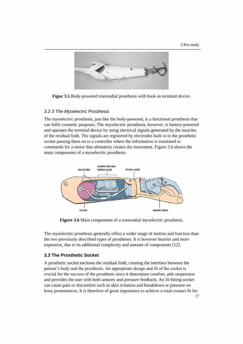
3.2.3 The Myoelectric Prosthesis
The myoelectric prosthesis, just like the body-powered, is a functional prosthesis that
can fulfil cosmetic purposes. The myoelectric prosthesis, however, is battery-powered
and operates the terminal device by using electrical signals generated by the muscles
of the residual limb. The signals are registered by electrodes built in to the prosthetic
socket passing them on to a controller where the information is translated to
commands for a motor that ultimately creates the movement. Figure 3.6 shows the
main components of a myoelectric prosthesis.
Figure 3.6 Main components of a transradial myoelectric prosthesis.
The myoelectric prosthesis generally offers a wider range of motion and function than
the two previously described types of prostheses. It is however heavier and more
expensive, due to its additional complexity and amount of components [12].
3.3 The Prosthetic Socket
A prosthetic socket encloses the residual limb, creating the interface between the
patient’s body and the prosthesis. An appropriate design and fit of the socket is
crucial for the success of the prosthesis since it determines comfort, aids suspension
and provides the user with both sensory and pressure feedback. An ill-fitting socket
can cause pain or discomfort such as skin irritation and breakdown or pressure on
bony prominences. It is therefore of great importance to achieve a total-contact fit for

3 Pre-study
18
an even distribution of pressure while at the same time providing relief to mentioned
sensitive areas. By doing this, the residual limb is stabilised in the socket, minimising
energy and motion loss and increasing control of and response from the prosthesis.
Factors also necessary to take into consideration when designing the socket are
Amputation level – length of the residual limb.
Type of prosthesis – a myoelectric prosthesis, for example, require a socket
with space for placement of electrodes.
Intended use of the prosthesis – everyday use or specific purpose.
Type of suspension – how the socket attaches to the body.
The socket consequently needs to be custom-fabricated according to the anatomy,
requirements and preferences of each individual amputee. In addition, since the shape
and size of the residual limb tend to change over time, due to weight gain or loss,
swollenness or, as in the case of a child, growth, a new socket needs to be created
from time to time.
Several materials can be used when creating the socket; common is to laminate the
socket with plastic resin and carbon fibre or fibreglass as reinforcements, resulting in
a lightweight, durable but expensive socket, or using a thermoplastic – easy to
modify, less expensive but also less durable and slightly heavier. Different options are
also available for the inner surface of the socket that is in direct contact with the
residual limb; the hard, laminated socket or its thermoplastic counterpart can be used
as they are or a gel liner interface can be added [3, pp.178-187, 281]. Common is also
to create an inner socket made from silicone stabilised with a laminated outer support
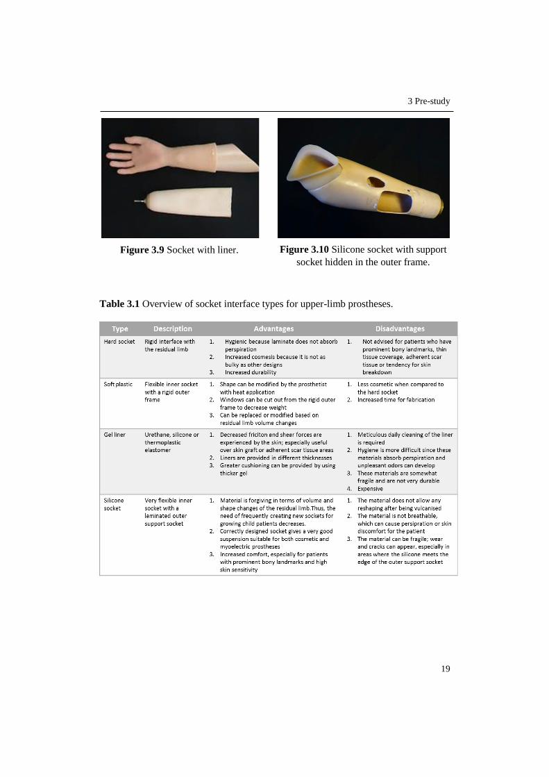
socket [4]. Examples of these four options are given in Figure 3.7-3.10 and their
respective advantages and disadvantages are further described in Table 3.1.
Figure 3.7 Laminated hard socket. Figure 3.8 Thermoplastic socket.
3 Pre-study
19
Table 3.1 Overview of socket interface types for upper-limb prostheses.
Figure 3.9 Socket with liner. Figure 3.10 Silicone socket with support
socket hidden in the outer frame.
3 Pre-study
20
3.3.1 Suspension Systems
The suspension system determines how the prosthetic socket attaches to the user’s
body and can be either self-suspending or non-self-suspending. Self-suspension is
achieved by using the anatomy of the residual limb, either by indirect skeletal
attachment, soft tissue constriction/friction or suction/skin friction.
Self-suspension is the most common type for transradial sockets and the indirect
skeletal attachment is the method most frequently used to achieve that suspension.
Indirect skeletal attachment involves contouring of the bone prominences of the
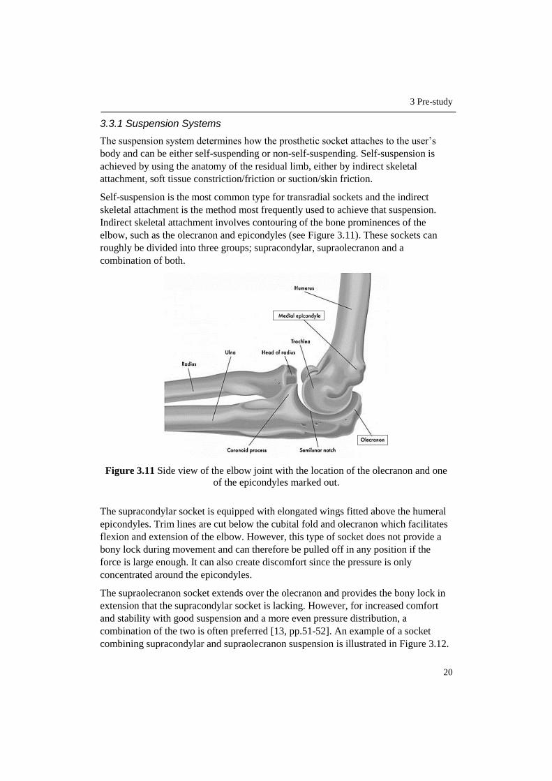
elbow, such as the olecranon and epicondyles (see Figure 3.11). These sockets can
roughly be divided into three groups; supracondylar, supraolecranon and a
combination of both.
Figure 3.11 Side view of the elbow joint with the location of the olecranon and one
of the epicondyles marked out.
The supracondylar socket is equipped with elongated wings fitted above the humeral
epicondyles. Trim lines are cut below the cubital fold and olecranon which facilitates
flexion and extension of the elbow. However, this type of socket does not provide a
bony lock during movement and can therefore be pulled off in any position if the
force is large enough. It can also create discomfort since the pressure is only
concentrated around the epicondyles.
The supraolecranon socket extends over the olecranon and provides the bony lock in
extension that the supracondylar socket is lacking. However, for increased comfort
and stability with good suspension and a more even pressure distribution, a
combination of the two is often preferred [13, pp.51-52]. An example of a socket
combining supracondylar and supraolecranon suspension is illustrated in Figure 3.12.

3 Pre-study
21
Figure 3.12 Line drawing of an example of a transradial socket using a combination
of supracondylar and supraolecranon suspension.
Self-suspension for a transradial socket can also be achieved by using a liner or
sleeve, often made from silicone. This method is more common in cases where the
socket does not suspend over the elbow. The liner or sleeve is pulled over the residual
limb and used in combination with suction, friction or by adding a pin at the bottom
to lock it to the prosthesis.
The non-self-suspending sockets are dependent on external devices to stay in place
over the residual limb. Most commonly used is a harness across the torso and
shoulders. A harness can be used for self-suspending sockets as well, but in such case
with the purpose of controlling the terminal device of a body-powered prosthesis [3,
pp.178-187, 281].
3.3.2 Conventional Manufacturing Method
Within the prosthetics industry, including Aktiv Ortopedteknik, the most widely used
method of fabricating a prosthetic socket is by first creating a plaster model of the
patient’s residual limb. This is followed by the creation of a test socket, one or several
fittings and adjustments before the final socket can be created and incorporated with
the prosthesis.
It is a rather tedious process involving several manual steps [4]. Figure 3.13 shows an
overview of the conventional manufacturing process. These steps are also further
described in the following sub-chapters according to a publication on upper-extremity
limb fitting by the Amputee Coalition of America [14].
Figure 3.13 Workflow displaying the steps and approximate timeframe of the
conventional manufacturing method for a prosthetic socket.

3 Pre-study
22
3.3.2.1 Measurement & Casting
Before initiating the casting procedure, the prosthetist covers the patient’s residual
limb with a thin casting sock or a liner, whereupon instructions are given to the
patient on how to position the limb. Measurements are then taken of the length of the
residual limb as well as of the opposite arm, in order to have a corresponding
prosthesis. To document the volume of the residual limb, the circumference of several
areas are also measured.
When the measurements are taken, the location of bony prominences, e.g. olecranon
and condyles, and sensitive areas in need of pressure relief are marked by the
prosthetist on the casting sock (see Figure 3.14). If the socket is intended for a
myoelectric prosthesis, placement of the electrodes are also marked out.
Figure 3.14 Bony prominences, electrode placement and trim lines marked out on the
casting sock.
Wet plaster bandage is then wrapped around the residual limb to create a negative
mould. The plaster is shaped by the prosthetist to closely fit over the limb while also
relieving sensitive and bony areas. After the cast has set it is removed from the
patient’s body (see Figure 3.15). This needs to be done carefully to avoid discomfort
for the patient and distortion of the cast. Liquid plaster is then poured into the cast to
create a positive mould of the residual limb and is left to dry and harden.
Figure 3.15 Removal of the cast from the patient’s residual limb.

3 Pre-study
23
3.3.2.2 Modification of Mould
When the liquid plaster has dried and hardened, it is removed from the bandage cast.
The marks previously made on the casting socket have now been transferred via the
cast to the filled mould and can be used as guidelines for modifications. Plaster is
added to bony areas (see Figure 3.16) while plaster in areas with more soft tissue is
removed with a file. This is a crucial stage for the fit of the resulting socket and the
skill and experience of the prosthetist plays an important role. Extra time is taken to
create a smooth finish since the outer surface of the mould will form the inner surface
of the socket.
Figure 3.16 Manual modifications of the positive plaster mould.
3.3.2.3 Create Test Socket
After modifications are made of the positive plaster mould it is used to create a test
socket. It is commonly made from transparent thermoplastic that is vacuum formed
around the mould, see Figure 3.17.
Figure 3.17 Vacuum forming of the test socket.
Consideration to space for myo-electrodes is also taken when creating the test socket.
The electrodes are represented by so-called dummies, which have the same shape and
size as the electrodes but without the electrical function, see Figure 3.18.

3 Pre-study
24
Figure 3.18 Actual electrodes to the left, electrode dummies to the right.
The dummies are attached to the mould before the vacuum forming, according to the
previously made placement markings.
In cases where the socket interface is intended to be made from silicone, no test
socket is created before the final socket. This is due to the difficulty of imitating the
properties of silicone with another material. The created silicone socket is therefore
used for the finished prosthesis and if it ends up not fitting, a new one has to be made
from scratch [4]. The silicone is shaped over the plaster mould and later cured in an
oven through vulcanisation [15].
3.3.2.4 Fitting & Adjustments
The test socket, such as the one shown in Figure 3.19, is used to assess the fit of the
socket on the patient. Volume, trimlines, motion range of the joint and the ease of
donning and doffing the socket are evaluated. If necessary, adjustments are made by
softening the plastic with a heat gun, allowing the socket to be reshaped. To increase
motion range and comfort, the trimlines can be cut, lowered or flared out.
Figure 3.19 Example of a transparent test socket with windows created for placement
of electrodes.
Alignment marks for the prosthesis are also made. In case of a myoelectric prosthesis,
the arm can be roughly assembled to investigate the impact of the weight on the
socket fit as well as the positioning of the electrodes.
When the prosthetist and the patient have agreed on the shape and fit of the socket,
the construction of the final socket can commence.

3 Pre-study
25
3.3.2.5 Create Final Socket
The initially created plaster mould often breaks during the removal of the test socket.
Therefore, when fabricating the final socket, the test socket is filled with liquid plaster
in order to create a new mould. After the plaster has dried the test socket is cut off the
mould. The final socket is then constructed by either laminating plastic resin (see
Figure 3.20) with reinforcing materials such as fibreglass or carbon fibre or by
vacuum forming a thermoplastic over the mould, just as in the procedure of the test
socket [4].
Figure 3.20 Lamination of the socket with plastic resin.
In the case where the socket interface is made from silicone, a support socket is
laminated on top of the silicone to add stability and an attachment surface for
prosthetic components. The silicone socket is later glued to the inside of the support
socket [15].
When the socket is finished and again fitted to the patient, further work of completing
the prosthesis and aligning its components can begin.
3.4 3D Technology
3.4.1 3D Scanning
3D scanning is the process of creating a 3D digital copy of an already existing object.
A variety of scanning technologies are available and based on the use of lasers, lights
or x-rays to capture the size, shape and colour of an object.
3D scanning has evolved from exclusively being an expensive technology in
professional and industrial devices to offering a wider scope including more
affordable options of hand held scanners and even smaller scanners that can be
integrated with a regular iPad or smartphone. Companies such as Google and
Microsoft have even developed hardware that allow their users to create 3D scanners
in their own homes. An example of this is Microsoft’s XBOX game controller Kinect
[5].

3 Pre-study
26
3.4.2 3D Printing
3D printing, also known as additive manufacturing, is a process of creating three
dimensional objects from a digital file. The file can be created from a CAD-drawn
model or from a 3D scan of an existing object. A software slices the model into thin
layers given as instructions to the printer that builds the physical object layer by layer.
The technology allows the creation of more complex geometries than what is offered
by many conventional manufacturing methods and also contributes to a more efficient
use of materials, reducing the amount of waste material in the manufacturing process
[5].
Three of the most common 3D printing processes relevant and available for this
project are further described in the following three subchapters.
3.4.2.1 Fused Deposition Modelling (FDM)
Fused deposition modelling is a material extrusion process where a plastic filament or
a metal wire from a spool is heated, melted and distributed through a nozzle, see
Figure 3.21.
The most commonly used plastic materials for the FDM process is ABS
(Acrylonitrile Butadiene Styrene) and PLA (Polylactic acid). The material is
deposited on a building platform, one layer at a time and hardens and bonds to the
previous layer immediately after being extruded. This continues until the complete
object has been built. If the object has overhanging geometry, support material needs
to be added. This extra material can however be removed after the print is finished
[5].
Figure 3.21 The principle of the FDM process.

3 Pre-study
27
3.4.2.2 Stereolithography (SLA)
Stereolithography, or SLA, is a process where an ultraviolet laser is used to cure a
liquid photopolymer resin held in a container, see Figure 3.22. The object is built
layer by layer as a result of the laser tracing a cross-section of the object on the
surface of the resin. The resin cures, hardens and bonds to the previous layer when
exposed to the laser. In between creating the layers, the elevator platform descends a
distance equal to the thickness of a layer, allowing a new coat of liquid resin to cover
the part. This process is repeated until the object is complete. The object is then
cleaned with a liquid solvent in order to remove excess resin and then further cured in
an ultraviolet oven.
As with the FDM technology, support material is necessary in this process for
overhanging geometries, to attach the object to the platform and keep it from floating
in the liquid resin. The support material can be removed after printing is finished.
SLA is considered to be one of the most precise 3D printing technologies due to the
excellent surface finish of the printed objects. Disadvantages, however, are the post-
processing steps and the tendency of the materials to become more brittle over time
[16].
Figure 3.22 The principle of the SLA process.
3.4.2.3 Selective Laser Sintering (SLS)
The SLS technology, as seen in Figure 3.23, is in many ways similar to the one of
SLA, but instead of liquid resin, SLS uses a powder of plastic, metal, ceramic or
glass. A high power laser fuses the powder particles together by tracing layers of the
3D object one by one on a powder bed. In between each layer the powder bed
descends by the thickness of one layer followed by a levelling drum or roller
distributing a new layer of powder on top. This procedure continues until the whole
object is finished.

3 Pre-study
28
As opposed to the FDM and SLA process, SLS does not need any separate support
material since all unused powder remains around the object providing a natural
support structure. Much of the remaining powder can also be reused for the next print
session [5].
Figure 3.23 The principle of the SLS process.
3.4.3 Applications in the Field of Medicine & the Prosthetics Industry
As the 3D technology has evolved, so has its application in various fields. When it
comes to medicine, 3D printing is for example used to fabricate anatomical models
for surgeons to simulate complex operations, in pharmaceutical research to
personalize dosages and creating multi-dosages and in the new, evolving application
bio-printing where living cells are used for 3D printing of human tissue for organs
and body parts. Bio-printing is however still at an early development stage.
Furthermore, 3D scanning and printing have enabled the customisation of prostheses,
orthoses and implants [17]. However, in the prosthetics industry, the largest
manufacturers have not yet adopted 3D printing on a larger scale. Most prostheses are
created according to a range of standardised sizes and appearances of the components,
often by using more traditional machining processes based on subtractive
manufacturing, while other prosthetic parts that are more customised, such as the
socket, often involve a great deal of manual work to produce [18], [4]. Nevertheless,
some collaborations between large prosthetic manufacturers and smaller companies
focusing on 3D technology and the personalisation of prostheses are starting to appear
[19], [20].

3 Pre-study
29
Several projects involving the creation and implementation of custom-made
prostheses using 3D technology have received public attention. One of these is “A
Leg That Fits”, see Figure 3.24 - a prosthetic leg where not only function but also
aesthetics was given a central role, demonstrating much of the potential of using 3D
technology in the manufacturing and personalisation of prostheses [21].
Figure 3.24 A Leg That Fits - a customized 3D printed prosthetic leg.
Over the last few years, a number of non-profit organisations using 3D printing to
create custom-made and affordable prostheses have emerged. One of the most
established is e-Nable, an open source community where 3D printed prosthetic hands
(see Figure 3.25) and arms are provided for free to those in need [22].
Figure 3.25 The Raptor Reloaded, one of the hand designs from e-Nable.
Other organisations such as Project Daniel, Nia Technologies and 3D LifePrints focus
on using 3D technology to provide amputees in developing countries with prosthetic
devices [23], [24] & [25].


31
4 Define
In this chapter the start and end points of the process are defined and results of a user
study is presented. The user study clarifies who the main user is and the identified needs
of the user with regards to the process. The needs are interpreted and converted into
process requirements that are ranked in relation to each other and used as guidelines
in the future work of developing the new process.
4.1 Process Start and End Point
As previously stated, the desired output of the process to be developed is a perfectly
fitted prosthetic arm socket. Hence, when the patient has been provided with a ready-
to-use socket, the end point of the process has been reached. However, in order to
give the socket its customised features, patient data regarding shape and size of the
residual limb is necessary. This data will be the primary input to the process and the
activity of collecting the data, the start point. Together with start and end points, all
intermediate steps are to be determined, adapted and described to ultimately form the
new process.
A simple visualisation of the input-output relation is shown in Figure 4.1.
Figur 4.1 Primary input and output of the process.
4.2 User Study
4.2.1 The User
The primary user of the new process is the maker of the socket, generally a
prosthetist. The prosthetist takes part in all stages from measuring, designing,
producing, and fitting of the socket with a patient in the current process.

4 Define
32
4.2.2 User Needs
An in-depth interview was conducted with two employees at Aktiv Ortopedteknik in
Lund; Christian Veraeus, prosthetist and Sven-Olof Frank, prosthetist and orthopaedic
manager.
Table 4.1 shows statements from the interviewees interpreted into user needs. The
importance of these needs where later rated by the user on a scale of 1-5, where 5 is
Critical process feature and 1 is Unnecessary process feature.
Table 4.1 User statements interpreted into user needs and their rated importance.
Topic Statement User Need Imp. Issues with the
current way of
manufacturing.
There are many steps to create the mould of the
residual limb. Fewer steps to
create the socket. 4
A socket can take up to 2 weeks, +- a few days,
from start to finish.
Shorter lead time
of the socket. 4
There are many human errors and manual
processing involved, hence a constant error
margin.
The process is
accurate. 5
It is difficult to go back in the process to make
changes with precision. Ability to make
detailed changes. 4
Making the initial cast mould is a rather messy
and smudgy procedure, which is not very
appreciated.
The process is
tidy. 3
The cast has to remain on the patient’s residual
limb until it has dried and hardened. The process
of later removing the cast can sometimes create
discomfort for the patient. Methods are
gentle to the
patients.
4 Child patients often need to be held down when
making the initial cast mould. This can be an
unpleasant experience.
Advantages of
the current
way of
manufacturing.
The current manufacturing method gives you a
type of muscle memory knowing where the soft
and bony parts are located.
Ability to identify
and visualise the
patient’s anatomy. 4
Material-wise, making the cast mould is cheap. Material is
inexpensive. 3
Important
aspects of a
new process.
I want to feel that I am in control of the process. The process is
easy to manage. 4
I want the result to be what I envision beforehand.
The process can
create a product
aligned with the
initial idea.
4
When learning a new method, I prefer a
combination of theoretical and practical
instructions.
Process
instructions are
presented both in
writing and
practise.
3

4 Define
33
Previous
experience.
CAD/CAM and scanners do exist in the company
but are used for orthoses and lower-limb sockets
preparing them for milling. It is not exactly a part
of the work tasks to use CAD, but we have a
software for creating insoles, however, it is very
simple and customised for the purpose of just
making insoles.
3D technology
and software are
easy to learn.
3
We don't have any 3D printers so the experience
is very low.
The patient.
Every patient is unique which also applies to the
sockets. Possibility to
create different
types of sockets.
4
Most patients start with a cosmetic prosthesis,
some decide to have both a cosmetic and a
myoelectric. When making the socket for a myoelectric
prosthesis, dummies need to be used to create
space for electrodes.
If the amputation is due to e.g. an accident, the
look of the residual limb can differ a lot and have
more areas that are sensitive or sore. The process is
adaptable.
4 Some amputations leave a lot of soft tissue while
others have mostly bony parts. This affects how
the feel of different materials are experienced and
also the look of the socket.
4.3 Process Requirements
User needs identified in the previous subchapter were categorised and converted into
process requirements. By using the importance rating of the needs, the requirements
were given a relative ranking, see Appendix B. These requirements are to function as
guidelines throughout the development of the process to ensure that user needs are
fulfilled.
In descending order of importance, the process requirements are:
Effective
Flexible
Efficient
Patient-friendly
Easy to learn and manage
Economical
The process should be effective in the sense of successfully producing the desired
result, allowing the user to go from idea to finished product and doing so in an
efficient way reducing the lead time of the socket.
Process flexibility is essential in order to meet each patient’s individual needs and
preferences in terms of comfort and fit of the socket and also since the socket design
differs depending on which type of prosthesis the patient chooses.

4 Define
34
The process should also be patient-friendly, not inflicting any pain or discomfort on
neither adult nor child patients.
Owing to the user’s limited experience in 3D technology the process should be easy
to learn and manage, giving the user a feeling of being in control of every step along
the way.
Furthermore, the process should be economical, financially competitive when
compared to the conventional way of manufacturing.
35
5 Identify
In this chapter essential steps to create an object with 3D technology are first identified.
This is followed by the steps being adapted to the case of producing a prosthetic socket.
Moreover, potential software to be used in the process is considered for further testing.
5.1 From Scan to Print - Generic Approach
As known from the very beginning of this project, the main tools to be used are 3D
scanning and 3D printing. When these tools are used in combination with each other
the scanner is essential in the initial step of capturing and digitalising the desired
object, whereas the printer is part of the production stage, creating the physical object
[26 pp.4-6], [27]. To get from start to finish, however, a series of intermediate as well
as additional finalising steps need to be completed in order to have an object ready to
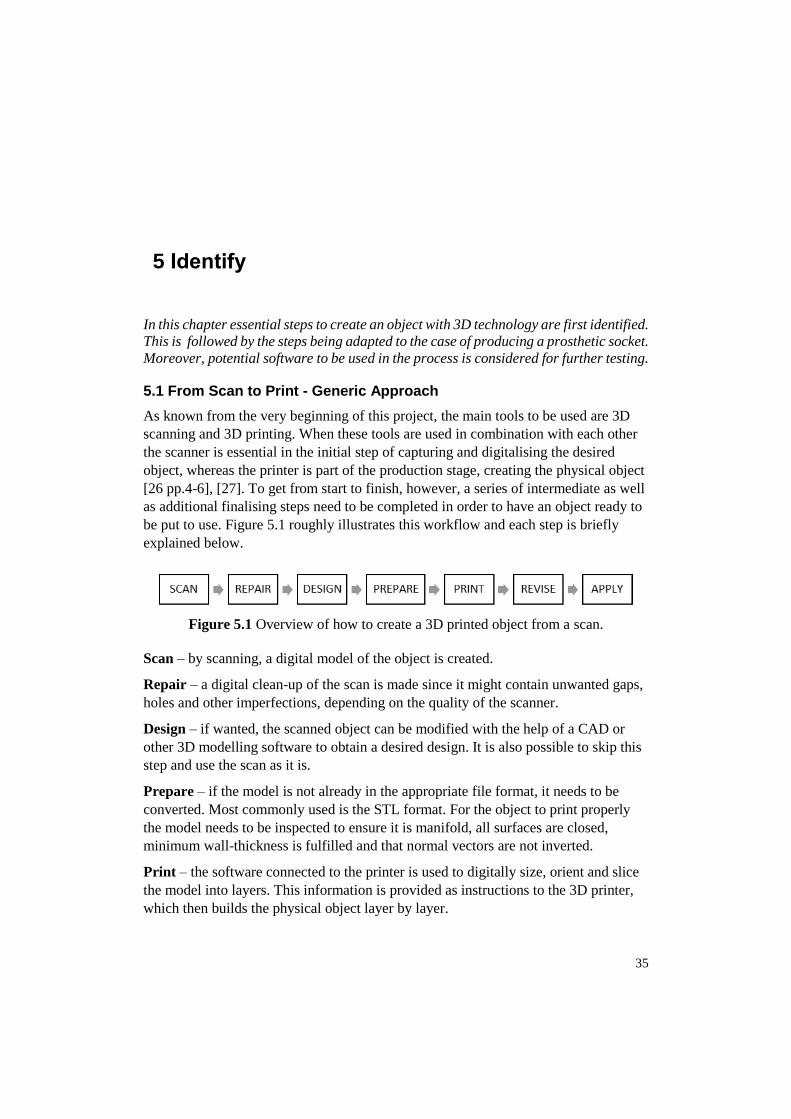
be put to use. Figure 5.1 roughly illustrates this workflow and each step is briefly
explained below.
Figure 5.1 Overview of how to create a 3D printed object from a scan.
Scan – by scanning, a digital model of the object is created.
Repair – a digital clean-up of the scan is made since it might contain unwanted gaps,
holes and other imperfections, depending on the quality of the scanner.
Design – if wanted, the scanned object can be modified with the help of a CAD or
other 3D modelling software to obtain a desired design. It is also possible to skip this
step and use the scan as it is.
Prepare – if the model is not already in the appropriate file format, it needs to be
converted. Most commonly used is the STL format. For the object to print properly
the model needs to be inspected to ensure it is manifold, all surfaces are closed,
minimum wall-thickness is fulfilled and that normal vectors are not inverted.
Print – the software connected to the printer is used to digitally size, orient and slice
the model into layers. This information is provided as instructions to the 3D printer,
which then builds the physical object layer by layer.

5 Identify
36
Revise – the printed object is inspected and post-processing such as removal of
excess material, painting etc. is performed if necessary.
Apply – the printed object is put to use.
5.2 From Generic to Adapted Approach
In chapter 4, the process start and end points were defined as “Collect patient data”
and “Provide patient with ready-to-use socket”. With this in mind and by using the
generic approach from the previous subchapter, an approach adapted to the case of
producing a prosthetic socket, see Figure 5.2, could be created and used as a main
structure for the further work of developing the process.
Figure 5.2 Adapted approach to creating a prosthetic socket with 3D technology.
Collect Patient Data – by 3D scanning the patient’s residual limb, data in terms of
shape and size is collected, resulting in a digital model of the limb.
Repair Scan – the digital scan might contain incomplete sections such as gaps and
holes. By using appropriate software these sections can be filled in and surface touch-
ups can be made to obtain a scan as corresponding to the actual limb as possible.
Create 3D Model of Socket – with the scan of the patient’s residual limb as
reference, a 3D model of the socket is designed. A CAD or 3D sculpting program is
required in this stage. Furthermore, adjustments of pressure points as well as space for
possible electrodes need to be taken into consideration when designing.
Prepare Socket for Printing – convert the socket model to the appropriate file
format and ensure that the file is printable.
Print Socket – the physical socket is 3D printed according to instructions generated
by the printer software.
Post-Processing – the printed socket is inspected and depending on the type of 3D
printer used, sanding or other surface processing methods might be necessary to
smoothen surfaces or remove sharp edges and excess material.
Ready-To-Use Socket – the patient can be provided with the custom fitted socket. If
electrodes are required, they are added in this stage.
As from now, further work of aligning the finished socket with the artificial limb can
begin.

5 Identify
37
5.3 Software
In order to edit the scan and create the socket before printing, 3D software is
necessary. A number of relevant software was therefore identified to eventually be
tested further along in the project. Due to time limitations, the number of software to
test was confined to three different options.
The list below comprises software already familiar to the writer of the thesis, as well
as software described in studied material [28], [29].
Blender – free software for 3D modelling, animation and rendering.
Meshmixer – free 3D modelling software from Autodesk.
Creo Parametrics 2.0 – sophisticated CAD software. License provided by Lund
University.
These software programs were selected to achieve a broad range in terms of interface
style, offered functions and sophistication.


39
6 Explore & Evaluate
This chapter describes the work of exploring different options when collecting patient
data and methods of modelling the socket. It involves becoming familiarised with
potential software followed by the evaluation and ultimately the selection of the best
suited modelling method and software to be used in the process.
6.1 Options for Collecting Patient Data
The first step of the new as well as the conventional process involves collecting
patient data. Since this, together with providing the finished socket, is the only step of
the new process where the patient is physically involved, the requirement “Patient-
friendly” needs to be taken into consideration.
Using a 3D scanner as the main tool for the initial step of the new process was known
from before. The scan of the residual limb will provide the foundation for shaping a
customised socket for each individual patient. Nevertheless, the scan itself does not
provide specific information of sensitive or less sensitive areas. This information has
to be obtained in dialogue with the patient.
As found during the pre-study, information regarding bony prominences, skin
sensitivity and soft tissue areas of the patient is crucial for the prosthetist to collect in
order to create a comfortable, well-fitting socket. In the conventional manufacturing
process this information is marked out with a water-soluble pen on the patient’s
residual limb when making the initial cast and transferred to the following plaster
model.
The only thinkable option to the method already in use would be to avoid the
markings. In this case, it would be necessary to rely solely on the prosthetist’s
memory from examining and speaking to the patient as well as making many
assumptions when modelling the socket. Naturally, the risk of creating an ill-fitting
socket would in this case be considered far greater than if the information was
visually available from the beginning and throughout the modelling procedure.
Since the 3D scanner to be used is able to capture colour, markings made on the
residual limb prior to scanning will subsequently be visible also on the digital model,
facilitating more precise adjustments when designing the socket. The activity of
making the markings is from the conventional process known to be rather swift and
also not a cause of discomfort or pain for the patient. The latter consequently verifies
the fulfilment of the established requirement “Patient-friendly”.
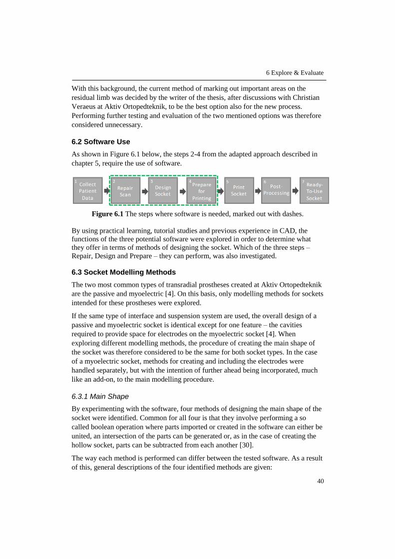
6 Explore & Evaluate
40
With this background, the current method of marking out important areas on the
residual limb was decided by the writer of the thesis, after discussions with Christian
Veraeus at Aktiv Ortopedteknik, to be the best option also for the new process.
Performing further testing and evaluation of the two mentioned options was therefore
considered unnecessary.
6.2 Software Use
As shown in Figure 6.1 below, the steps 2-4 from the adapted approach described in
chapter 5, require the use of software.
Figure 6.1 The steps where software is needed, marked out with dashes.
By using practical learning, tutorial studies and previous experience in CAD, the
functions of the three potential software were explored in order to determine what
they offer in terms of methods of designing the socket. Which of the three steps –
Repair, Design and Prepare – they can perform, was also investigated.
6.3 Socket Modelling Methods
The two most common types of transradial prostheses created at Aktiv Ortopedteknik
are the passive and myoelectric [4]. On this basis, only modelling methods for sockets
intended for these prostheses were explored.
If the same type of interface and suspension system are used, the overall design of a
passive and myoelectric socket is identical except for one feature – the cavities
required to provide space for electrodes on the myoelectric socket [4]. When
exploring different modelling methods, the procedure of creating the main shape of
the socket was therefore considered to be the same for both socket types. In the case
of a myoelectric socket, methods for creating and including the electrodes were
handled separately, but with the intention of further ahead being incorporated, much
like an add-on, to the main modelling procedure.
6.3.1 Main Shape
By experimenting with the software, four methods of designing the main shape of the
socket were identified. Common for all four is that they involve performing a so
called boolean operation where parts imported or created in the software can either be
united, an intersection of the parts can be generated or, as in the case of creating the
hollow socket, parts can be subtracted from each another [30].
The way each method is performed can differ between the tested software. As a result
of this, general descriptions of the four identified methods are given:

6 Explore & Evaluate
41
A1. Create a generic solid socket by using sketch planes at adjustable distances in
a CAD software. Each plane contains an ellipse, also with adjustable
dimensions. By using a blend or loft tool between the ellipses, a solid socket is
created. An adjusted scan of the residual limb is then imported and used to
subtract material from the solid shape created between the planes. This leaves
a hollow socket with the interface formed according to the residual limb.
A2. Import the scanned residual limb to the software and add or remove material
as necessary, according to previously made markings. Create a copy and scale
it slightly larger followed by shaping the trimlines. The original adjusted scan
is then used to subtract material, leaving a hollow socket with an interface
shaped according to the residual limb.
A3. Import the scanned residual limb to the software and add or remove material
as necessary. Create and keep a copy of the adjusted scan while using the
original to create an offset of selected areas. The offset value is set according
to the desired thickness of the socket. The created copy is now used to subtract
material from the offset scan, leaving a hollow socket.
A4. Scan a finished socket. Scale, thicken and manually adjust the shape in the
software followed by importing a scan of the residual limb that is modified
according to markings. Subtract the scan of the residual limb to create the
hollow socket.
In Table 6.1, advantages and disadvantages, as experienced by the writer, are
described for the respective modelling method and an overview showing which of the
software that can perform each method is given. Included is also which of the steps
Repair, Design and Prepare the software can manage.

6 Explore & Evaluate
42
Ta
ble
6.1
Ad
van
tages
and d
isad
van
tages
of
the
resp
ecti
ve
model
ling m
ethod a
s w
ell
as w
hic
h m
eth
od
an
d p
roce
ss s
tep
are
off
ered
by e
ach
so
ftw
are.
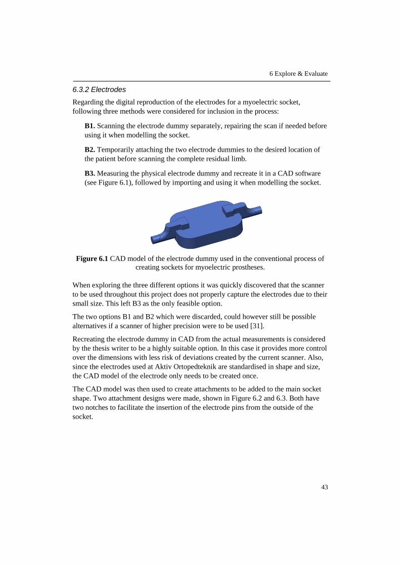
6 Explore & Evaluate
43
6.3.2 Electrodes
Regarding the digital reproduction of the electrodes for a myoelectric socket,
following three methods were considered for inclusion in the process:
B1. Scanning the electrode dummy separately, repairing the scan if needed before
using it when modelling the socket.
B2. Temporarily attaching the two electrode dummies to the desired location of
the patient before scanning the complete residual limb.
B3. Measuring the physical electrode dummy and recreate it in a CAD software
(see Figure 6.1), followed by importing and using it when modelling the socket.
Figure 6.1 CAD model of the electrode dummy used in the conventional process of
creating sockets for myoelectric prostheses.
When exploring the three different options it was quickly discovered that the scanner
to be used throughout this project does not properly capture the electrodes due to their
small size. This left B3 as the only feasible option.
The two options B1 and B2 which were discarded, could however still be possible
alternatives if a scanner of higher precision were to be used [31].
Recreating the electrode dummy in CAD from the actual measurements is considered
by the thesis writer to be a highly suitable option. In this case it provides more control
over the dimensions with less risk of deviations created by the current scanner. Also,
since the electrodes used at Aktiv Ortopedteknik are standardised in shape and size,
the CAD model of the electrode only needs to be created once.
The CAD model was then used to create attachments to be added to the main socket
shape. Two attachment designs were made, shown in Figure 6.2 and 6.3. Both have
two notches to facilitate the insertion of the electrode pins from the outside of the
socket.

6 Explore & Evaluate
44
After discussions with Christian Veraeus at Aktiv Ortopedteknik, attachment design 2
was chosen since it has a smoother transition to the socket, which would facilitate the
following work of completing the entire prosthesis.
The file containing the attachment and the dummy was saved and can easily be
imported every time it is needed during modelling.
6.3.3 Evaluation and Selection of Modelling Method
The identified modelling methods for the main socket shape were evaluated by using
a concept screening matrix, see Appendix C. Evaluation criteria were:
Ease of learning
Accuracy
Adaptability
Efficiency
Adjustability
Ease of learning refers to the possibility of quickly mastering the method of
modelling the socket.
The accuracy of the method is important in order to create the complete socket with
an overall precision and according to the initial idea.
Adaptability relates to being able to form the socket according to the shape and size
of the scanned residual limb.
In order to shorten the lead time, the efficiency of the method is highly relevant.
Adjustability is important to allow both minor and major design modifications while
modelling.
The concept screening resulted in the selection of modelling method A3 (Offset) as
the best suited option.
Figure 6.2 Attachment design 1.
Figure 6.3 Attachment design 2.

6 Explore & Evaluate
45
6.4 Software Evaluation & Selection
Since a central part of the process and determining factor for the process output is the
user’s interaction with the software, the requirements established for the complete
process in chapter 4 were used as criteria to evaluate the tested software. The
requirement “Patient-friendly”, however, was not included since the patient does not
interact with the software.
The evaluation was conducted by using a concept scoring matrix with the following
criteria:
Effective
Flexible
Efficient
Easy to learn and manage
Economical
For further descriptions of these criteria, refer to chapter 4.
The concept scoring, found in Appendix C, resulted in the selection of Meshmixer to
be used as software for the process.
According to the thesis writer, the chosen software is the most suitable for the
purpose of this project since the simple, uncluttered user interface enables an intuitive
navigation where key functions are easily accessed in the software - important aspects
when the user has little to no previous experience in 3D modelling.
The software is free and allows the user to easily adapt the design of the socket to
each individual patient. It is easy to undo operations and make detailed changes,
giving the user control over the process. The software can also perform all three of
the process steps – repair, design and prepare, which adds to process efficiency
compared to having to use several different software.


47
7 Create
This chapter describes the first round of process testing. Socket prototypes are created
by using the selected software and modelling method together with all necessary
hardware in order to better assess both process and socket quality and design before
involving actual patients.
7.1 Hardware
The hardware used for prototyping, as well as for the validation further ahead, is the
hand-held iSense 3D scanner and the EOS Formiga p110 3D printer. Both are
provided by the Department of Design Sciences at Lund University and further
described in the following two subchapters.
7.1.1 iSense 3D Scanner
The iSense scanner, see Figure 7.1, is a low-cost scanning device mounted on a
regular iPad. It uses laser technology where an invisible infrared laser pattern is
projected onto the surroundings and picked up by an infrared sensor to determine
distance. The iSense also has two cameras, where one captures geometry and the
other captures colour. All the collected data is then, by the scanner using a complex
algorithm, turned into a 3D model of the scanned object [32], [33].
Figure 7.1 The iSense 3D scanner used throughout this project.
7.1.2 EOS Formiga p110 3D Printer
The EOS Formiga p110, seen in Figure 7.2, uses the SLS technology described in
chapter 3.
After consulting Professor Olaf Diegel at the Division of Product Development at
Lund University, it was decided that the SLS technology is the most suitable for

7 Create
48
printing the sockets since it creates objects with high accuracy, close to equal quality
in all xyz-directions and with a good surface finish, requiring little post processing.
Figure 7.2 The EOS Formiga p110 3D printer available at the IKDC product lab at
Lund University.
7.1.2.1 Printing Material
The EOS Formiga p110 can print objects in a variety of materials, but the one used at
the product lab and thus for the sockets is PA2200, also known as polyamide 12 or
nylon 12. It is a thermoplastic that gives the printed parts a white colour. It can
however be dyed or painted to achieve a variety of other colours as well [34].
PA2200 has material properties such as flexibility, high strength, excellent long-term
constant behavior and biocompatibility – properties that make it suitable to use e.g.
for prosthetic parts [35]. For more detailed information regarding material properties,
refer to the Material Data Sheet in Appendix D.
7.2 Socket Prototypes
To create the first prototype, a plaster model from Aktiv Ortopedteknik was used to
imitate the residual limb, see Figure 7.3. Due to the lack of flexibility in the plaster
model, as opposed to an actual limb, the fit of the prototype could not be tested at this
stage.
For the second prototype, a scan of an actual limb was used, see Figure 7.4. Since no
amputee patients were yet involved, a healthy arm was scanned and adjusted in the
scanner software. This was decided by the writer of the thesis in order to practice
modelling sockets for different shapes of residual limbs. As in the case of the first
prototype, the socket fit could not be tested. However, markings to indicate trimlines,
condyles, electrode placement and areas to remove or add material were still made on
the plaster model and healthy arm to simulate the initial step of the actual future
process.

7 Create
49
After discussions with the prosthetist Christian Veraeus and Jonny Nyman, research
engineer at the ID-A workshop at Lund University, the general wall-thickness of the
sockets was set to two millimeters. Due to the fact that it is the average wall-thickness
of the current sockets made at Aktiv Ortopedteknik and also after inspecting
previously printed objects at the product lab, two millimeters was decided to be a
suitable first choice.
After being modelled and printed, post-processing of the sockets was made in terms
of removing excess powder and smoothening of surfaces by sanding with 800-1000-
grit sandpaper.
7.2.1 First Prototype
A socket intended for a passive prosthesis was first prototyped, see Figure 7.5 for
both the digital and printed version.
Figure 7.5 Digital and printed version of the first socket prototype.
Figure 7.3 Plaster model used
for the first prototype.
Figure 7.4 Scan of healthy arm
adjusted in the scanner software
and used for the second prototype.

7 Create
50
7.2.2 Second Prototype
Secondly, a myoelectric socket was prototyped where the previously created electrode
attachment was twice added to the model, one on each side. After being printed, an
electrode was fitted to each attachment. Figure 7.6 shows both the digital and physical
version of the prototype.
Figure 7.6 The digital and printed version of the second socket prototype, intended
for a myoelectric prosthesis.
7.2.3 Third Prototype
The two previously created prototypes are firm and robust, much alike the hard
laminated sockets made in the conventional way of manufacturing. Similar to a
laminated socket, they lack the flexibility provided by a thermoplastic or silicone
socket.
In order to provide a more flexible option when it comes to the 3D printed sockets, a
third prototype was later designed and printed, see Figure 7.7. Just as the first two
prototypes, the third was modelled using the previously selected software Meshmixer.
Figure 7.7 The digital and printed version of the third, more flexible socket
prototype.

7 Create
51
The prototype design has an added lattice pattern and an overall wall-thickness of two
millimeters, were the pattern constitutes one millimeter and the smooth solid part of
the socket was reduced to one millimeter. This provides the socket with increased
flexibility while maintaining stability.
Obtaining a socket with equal flexibility and softness as a silicone socket is however
not possible due to the difference in properties of the available printing material.
7.3 Assessment
The prototypes were assessed by consulting the prosthetist Christian Veraeus. Socket
design was discussed and a summary of expressed opinions are listed below.
Two millimeter wall-thickness works well for the sockets. Reducing the
thickness to one and a half millimeter for the standard smooth socket could also
be an alternative if a slightly more flexible socket is needed.
The trimline shape of the second prototype should be more similar to the ones
of the first and the third prototype – a deeper opening in the front near the bend
of the arm and reach slightly higher above olecranon.
The third prototype with the lattice pattern is a very good complement to the
standard smooth socket, both in terms of aesthetics and function. The pattern
provides a structure that facilitates the attachment of fairings in the further
work of assembling the entire prosthesis.
The overall shape of the electrode attachments would also work very well in
the further work of completing the prosthesis. The cavity created for the
electrode itself could however be slightly narrowed and the notches added to
facilitate the insertion of the electrode pins, rotated 180 degrees to the inside
of the socket. This is to avoid the risk of the electrodes being pushed out of the
attachments when exposed to pressure from the residual limb. These
adjustments would mean that the electrodes need to be inserted from the inside
of the socket instead of the outside, which, according to Christian Veraeus, will
not be an issue in the assembly.
Based on the discussion, a mutual decision was made that after minor adjustments of
the electrode attachment and by keeping the assessment result in mind, the process
was ready to be tested with actual patients.
7.4 Iteration
To ensure that the desired adjustments of the electrode attachments are correctly
made before proceeding, one attachment was 3D printed and fitted with an electrode,
see Figure 7.8.

7 Create
52
Figure 7.8 The digital and printed version of the revised electrode attachment.
The width and inner edge radius of the attachment cavity were reduced by one
millimeter each and the notches were rotated 180 degrees from the top of the
attachment to the bottom.
As desired, the adjustments secured the positioning of the electrode, preventing it
from being pushed out of its attachment when exposed to pressure from the residual
limb.

53
8 Integrate
The knowledge and information acquired thus far is in this chapter used to compile the
complete process. In order to have a clear overview of the procedure, each of the seven
previously defined steps is divided into several substeps.
8.1 Compilation of Final Process
By integrating the findings from preceding phases with the structure of the adapted
approach established in chapter 5, see Figure 8.1, the main steps of the elaborated
process were broken down into substeps.
Following subchapters describe these steps and related substeps further.
Figure 8.1 The seven steps of the adapted approach described in chapter 5.
8.1.1 Collect Patient Data
As described in Figure 8.2, the process starts with the prosthetist, in dialogue with the
patient, marking out important areas of the residual limb that need to be taken into
consideration when modelling the socket. These involve areas in need of pressure
relief or additional pressure. Shape and location of trimlines are also marked out as
well as placement of electrodes if the socket is intended for a myoelectric prosthesis.
This is followed by the prosthetist instructing the patient on how to position the
residual limb. Thus far the procedure follows the conventional way.
Finally, the residual limb is scanned by the prosthetist and the file is saved to the iPad
connected to the scanner.

8 Integrate
54
Figure 8.2 Substeps of collecting patient data.
8.1.2 Repair Scan
The saved file containing the scanned residual limb is transferred from the iPad to the
computer, where it is imported into the software Meshmixer.
The scan is inspected to determine if it contains any incomplete sections such as holes
or other unwanted features. These sections can be filled in either by using the
automatic repair function of the software or by manually performing necessary
surface touch-ups, in order to obtain a scan as corresponding to the actual residual
limb as possible.
Figure 8.3 below summarises the subtasks of this process step.
Figure 8.3 Substeps of repairing the scan of the residual limb.
8.1.3 Design Socket
By digitally adding or removing material according to the markings made before
scanning, necessary pressure points as well as trimlines are adjusted in the software.

8 Integrate
55
Copies are made of the scan to keep as reference and for hollowing out the socket
further ahead in the modelling procedure.
The areas needed for the socket are selected on the adjusted scan and used to create
an offset with the same value as the desired thickness of the finished socket. One of
the previously created copies of the adjusted scan is now used in a boolean operation
to subtract material, leaving a hollow socket.
After this, complementary shaping of the trimlines and surface smoothening of the
socket is performed. For a plain socket intended for a passive prosthesis, this is the
last substep of designing the socket.
In the case of a myoelectric prosthesis, two additional substeps are included, marked
as blue in Figure 8.4 below. These involve importing the file containing the electrode
module and placing one on each side of the socket, followed by subtracting the
accompanied electrodes. This is also performed through a boolean operation, in order
to create the necessary cavity all the way through the socket wall.
To apply a pattern to the passive or the myoelectric socket, similar to the third
prototype created in chapter 7, another substep, marked as orange in Figure 8.4, is
added to the process.
Figure 8.4 Subtsteps of designing the socket.

8 Integrate
56
8.1.4 Prepare for Printing
To ensure that the modelled socket is printable, it needs to be inspected. Just as in the
Repair Scan step, this can be done by using the Inspector function in the software.
The function will indicate if the model contains imperfections such as holes, non-
manifold edges or disconnected parts. These imperfections are corrected either by
using the automatic repair function or by manual correction, one by one.
When no imperfections remain, the model is finally exported as an STL-file. The
whole sequence of substeps can be seen in Figure 8.5 below.
Figure 8.5 Substeps of preparing the socket for printing.
8.1.5 Print Socket
Since no 3D printer is currently available at Aktiv Ortopedteknik, the STL-file
containing the modelled socket can be sent to a prototype workshop, such as the
product lab at Lund University. An alternative is online 3D printing services such as
Shapeways and Sculpteo, where an uploaded file can be printed and shipped to the
customer. For additional fees, the printed object can also be post-processed and
coloured. The use of online printing services will however not be further investigated
in this report.
The only action necessary from the prosthetist, is providing the STL-file to the chosen
printing service. All tasks involving the actual printing procedure and the removal of
the model from the machine are handled by the printer operator. These tasks, such as
generating printer instructions, operating the printer in general as well as rinsing or
blastering the model after cooling, were therefore consolidated under the name Print,
without being further specified or described, see Figure 8.6.

8 Integrate
57
Figure 8.6 Substeps of printing the socket.
8.1.6 Post-Processing
The printed socket is inspected by the prosthetist to identify areas particularly in need
of refinement. Excess powder left from printing is removed and the inside of the
socket that will be in direct contact with the patient’s skin may require extra surface
smoothening. This can be performed by polishing the surface with a fine-grit
sandpaper.
Figure 8.7 below shows the three substeps of post-processing the socket.
Figure 8.7 Substeps of post-processing.
8.1.7 Ready-To-Use Socket
For a myoelectric socket, the electrodes are mounted to the attachments in this stage.
This additional substep is marked as blue in Figure 8.8 below.
The socket can now be fitted with the patient and a myo-test of the electrodes are
performed when needed. If necessary, minor adjustments are made and could involve
using sandpaper to further smoothen the socket surface or a heat gun for reshaping
smaller areas of the socket.
Hereafter, the finished socket can be used in the further work of completing the entire
prosthesis for the patient.

8 Integrate
58
Figure 8.8 Substeps of the last step in the process.
59
9 Validate
This chapter describes the validation of the elaborated process, where case studies
involving two patients are performed as proof-of-concept. By following the previously
established steps, a custom fitted socket is produced for each patient in order to
determine process viability.
9.1 Case Studies
The case studies were performed partly at Aktiv Ortopedteknik and partly at Lund
University. The first and the last step of the in total seven step process, described in
chapter 8, were performed at Aktiv Ortopedteknik. These are Collect Patient Data
and Ready-To-Use Socket. Step two to six; Repair Scan, Design Socket, Prepare for
Printing, Print Socket and Post-Processing were performed at Lund University.
The task handled by the prosthetist in the first step was marking out important areas
of the residual limb. For the last step, the patient fitting was handled by the
prosthetist. Remaining tasks were performed by the thesis writer.
After consulting Professor Olaf Diegel, performing two case studies were considered
to be sufficient as proof-of-concept for the process. Moreover, after discussions with
the prosthetist, it was decided that both case studies should involve a myoelectric
socket. This is due to the process of creating the socket for a myoelectric prosthesis is
identical to the one for a passive, except for the added electrode attachments. Hence,
by using myoelectric sockets the validation applies to both processes.
9.1.1 Case Study 1
9.1.1.1 Patient Information
The patient is a two-and-a-half-year-old girl with a congenital, transradial amputation
on her left arm.
The residual limb, see Figure 9.1, is of medium length and with normal amount of
soft tissue for her age and reason for amputation. There is no scarring or additional
bone prominences to take into consideration, except for olecranon.
The patient has had a passive prosthesis since the age of five months and will soon
receive her first myoelectric prosthesis.

9 Validate
60
Figure 9.1 The residual limb of the first patient.
9.1.1.2 Result
The 3D printed socket was donned on the patient with the help of some vaseline,
which is common during patient fittings. Figure 9.2 shows the patient wearing the
socket.
Figure 9.2 The patient wearing the socket.
According to the prosthetist, the socket had a perfect volume and the myo-test
indicated a good contact between the electrodes and the skin surface.
Due to the young age of the patient, evaluating statements from the patient herself
was difficult to obtain. However, the fact that the patient was wearing the socket for a
long time and with no complaints is according to the prosthetist a very good sign.
In addition, statements from the parent of the patient was very positive with regards to
aesthetics - slimlined design and the added pattern.

9 Validate
61
9.1.2 Case Study 2
9.1.2.1 Patient Information
The patient is a 34-year-old man with a congenital, transradial amputation on his left
arm.
The residual limb, seen in Figure 9.2, is of medium length and has a normal
distribution of soft tissue and bone prominences. There is no scarring.
The patient has been using a prosthesis since the age of three months. He currently
has both a passive and a myoelectric prosthesis, however the myoelectric is more
frequently used.
Figure 9.3 The residual limb of the second patient.
9.1.2.2 Result
The socket was donned and doffed independently by the patient, who can be seen
wearing the socket in Figure 9.4.
The fit and the material was considered by the patient to be comfortable, light and
with a perfect amount of space in the front of the socket.

9 Validate
62
Figure 9.4 The patient wearing the socket.
The shape of the trimlines were considered to be very good, not causing any chafing
against the skin.
The myo-test indicated a good contact between the electrodes and the skin surface.
The personal preference of the patient was however for the socket to be slightly
tighter over the electrode attachments, approximately one millimeter.
9.2 Validation Assessment
A follow-up discussion was held with the prosthetist after finishing the case studies.
By looking at opinions and statements from both the patients and the prosthetist
regarding fit, feel and appearance as well as the outcome of the myo-tests, both case
results were considered successful.
The one millimeter fit adjustment that would be necessary in the second case study in
order to achieve the perfect fit, is considered to be more a result of the thesis writer
lacking orthopedic and patient experience rather than a process flaw. Such a small
adjustment can be performed simply by using a heat gun. However, an important
learning from this, when keeping a dialogue with the patient during the Collect
Patient Data step, is to actively seek this type of information in order to detect
specific preferences of the patient regarding the fit. This can then be used when later
designing the socket.
Moreover, what could be done is to add slightly more flexibility in the movement of
the electrodes. This can easily be adjusted by, for example, increasing the diameter of
parts of the holes created for insertion of the rubber pins of the electrode, which
would allow for a freer perpendicular movement of the electrode in relation to the
residual limb. This, together with the one millimeter fit adjustment in the second case
study were however not considered to affect the process itself in terms of structure or
line of action. On this basis, the process was considered to be validated and thus no
iterative troubleshooting activity was carried out.

9 Validate
63
9.3 Extension of Case Study 1
After the validation sessions had been performed it was decided together with
Professor Diegel to extend the first case study. The extension involved the creation of
a complete cosmetic arm prosthesis integrated with a passive socket, see Figure 9.5.
This was however kept outside of the original process validation, but included in the
thesis as a way of displaying the role of the socket as well as to further demonstrate
some of the possibilities offered by 3D technology in the manufacturing of
prosthetics.
Figure 9.5 The 3D printed cosmetic arm prosthesis integrated with a passive socket.
Just as the previously made sockets, the arm was created using Meshmixer. The
intention was to 3D scan the healthy arm of the patient, mirror it and integrate it with
the socket. However, due to lack of time, an existing file of an arm was used instead.
It was then redesigned and resized according to patient measurements previously
obtained by the prosthetist.
The patient wearing the 3D printed arm can be seen in Figure 9.6.
Figure 9.6 The patient wearing the 3D printed arm.


65
10 Deliver
This chapter describes how the validated process is presented to the user in terms of
theoretical and practical instructions. The instructions are also evaluated together with
the user and lastly, a comparison between the new and the conventional process with
regard to lead times and costs is performed.
10.1 Process Instructions
By consulting the previous user study and in further discussions with the prosthetist,
the need of having access to a combination of theoretical and practical process
instructions was identified.
In order to facilitate the learning and implementation of the process, it was therefore
decided that a booklet and a video tutorial were to be created as learning material.
10.1.1 Booklet User Guide
The booklet, see Figure 10.1, was created as a complete step-by-step manual to the
elaborated process. It uses both images and text to describe each step, guiding the
user from start to finish.
Figure 10.1 The printed booklet user guide.
The finished booklet was printed in an A5-format and provided to the user both in
digital and printed versions. A version of the booklet, formatted to suit this report, can
be found in Appendix E.

10 Deliver
66
10.1.2 Video Tutorial
As a more hands-on complement to the written instructions, a video tutorial was
created to guide the user in the interaction with the software. This involves process
steps 2-4, Repair Scan, Design Socket and Prepare for Printing. When designing the
socket, the tutorial demonstrates the creation of the two traditional sockets types – the
plain passive and the plain myoelectric. To apply a pattern to the socket, the user is
referred to the written instructions.
Interacting with the software is, according to the thesis writer, the part of the process
requiring the most practice. A video tutorial was therefore considered to be a good
option to assist the user in quickly gaining proficiency. It can also be used alone or in
combination with the written instructions.
The video tutorial was provided to the user as a media file and an online link to the
video sharing platform Vimeo [36].
10.1.3 User Evaluation
Due to time limitations of this project, no extensive user evaluation was conducted
where the prosthetist independently could carry out the full process. Nevertheless, the
created learning material was presented to the user, who was asked to evaluate it in
terms of structure, content and comprehensibility.
Although not being able to perform the various tasks while going through the
material, the user expressed an overall positive review on all three evaluation points
and was of the opinion that the material would be of valuable assistance in gaining
proficiency in the process. However, by request of the user, a minor modification of
the video tutorial was made, where the part of demonstrating the adjustments of
pressure points and trimlines was slightly extended.
10.2 Process Comparison
The comparison between the conventional and the new process is made with regard to
lead-time and cost and allows to further determine the fulfilment of the two process
requirements Efficient and Economical that were defined together with four additional
requirements in chapter 3.
The comparison is done with regard to a plain, myoelectric socket made from plastic.
To be comparable, only sockets from the conventional process that have similar
properties as the ones that can be achieved with the current 3D printing material,
nylon 12, will be considered. Sockets made from silicone are therefore not taken into
account when comparing the processes.
During one year, an average of 150 transradial sockets are produced at Aktiv
Ortopedteknik in Lund. Out of these, 90 are plastic sockets that are distributed in
three different categories; Thermoplastic, Laminated and Thermoplastic with
laminated support socket. Due to the flexibility and softness of half of the sockets in

10 Deliver
67
the third category, these 50% will not be part of the comparison. This results in a total
of 67.5 sockets per year with properties comparable to the current 3D printing
material. This corresponds to 75% of the plastic sockets and 45% of all 150
transradial sockets produced during one year.
The relative distribution between the three categories of plastic sockets from the
conventional process as well as the number of sockets applicable for the process
comparison can be found in Table 10.1.
Table 10.1 Relative distribution between the three categories of plastic sockets as
well as the number of sockets created with the conventional process that are
applicable for the comparison.
PLASTIC SOCKETS
THERMOPLASTIC LAMINATED THERMOPLASTIC
WITH LAMINATED SUPPORT SOCKET
Transradial plastic sockets produced by the prosthetist (sockets/year)
90
Distribution (%) 15% 35% 50%
Distribution (sockets/year) 13.5 31.5 45
Applicable for comparison with Nylon 12 (%)
100 100 50
Applicable for comparison with Nylon 12 (sockets/year)
13.5 31.5 22.5
67.5
10.2.1 Lead Time
The total lead time for each process includes both time actively spent by the
prosthetist on the socket as well as time needed for drying of the plaster, cooling or
curing of the plastic, 3D printing time etc, i.e. time when the prosthetist is not bound
to the process.
Time approximations are based on a high level of proficiency for the conventional
process and an intermediate to high level of proficiency for the new process and with
the assumption that no step needs to be redone. Furthermore, for the new process,
time for printing of the socket is based on the use of Lund University as printing
service. Due to its proximity to Aktiv Ortopedteknik, no consideration is taken to
shipping time.
10.2.1.1 Conventional Process
An overview of the main steps of the conventional process is shown in Figure 10.2.
Figure 10.2 Main steps of the conventional manufacturing process.

10 Deliver
68
Based on time approximations from the prosthetist, lead time and active time for each
of the three categories of plastic sockets are specified for these five steps. Time
distribution and total time can be found in Table 10.2.
Table 10.2 Total lead time and active time per socket for the three categories of
plastic sockets using the conventional manufacturing process.
STEP
THERMOPLASTIC LAMINATED THERMOPLASTIC
WITH LAMINATED SUPPORT SOCKET
Total lead time (h)
Active time (h)
Total lead time (h)
Active time (h)
Total lead time (h)
Active time (h)
1. Measurements & Casting 2.5 1.5 2.5 1.5 2.5 1.5
2. Modification of Mould 1.5 1.5 1.5 1.5 1.5 1.5
3. Create Test Socket 2.5 1.25 2.5 1.25 2.5 1.25
4. Fitting & Adjustment 1.5 1.5 1.5 1.5 1.5 1.5
5. Create Final Socket 2.75 2 15 2.75 6 3.75
TOTAL 10.75 7.75 23 8.5 14 9.5
10.2.1.2 New Process
The time distribution of the new process, shown in Table 10.3, results in a total lead
time of 14.85 hours from start to finish, based on approximations made by the thesis
writer when carrying out the process.
Important to note is that the twelve hours required for the step Print Socket are six
hours for the printing itself and six hours for cooling of the plastic in the printer.
These twelve hours are time that can be spent doing other things. In other words, only
2.85 hours of the entire process requires the prosthetist to actively work on the socket.
Table 10.3 Total lead time and active time per socket, using the new process.
STEP
3D PRINTED SOCKET
Total lead time (h)
Active time (h)
1. Collect Patient Data 0.5 0.5
2. Repair Scan 0.2 0.2
3. Design Socket 0.75 0.75
4. Prepare for Printing 0.1 0.1
5. Print Socket 12 0
6. Post-Processing 0.3 0.3
7. Ready-To-Use Socket 1 1
TOTAL 14.85 2.85

10 Deliver
69
10.2.1.3 Time Comparison
Due to the difference in lead time and active time between the three categories of
plastic sockets in the conventional process, the comparison with the new process is
first made for each category separately, see Table 10.4.
Table 10.4 Comparison between the conventional and the new process with regard to
total lead time and time actively spent working on a transradial socket.
THERMOPLASTIC LAMINATED THERMOPLASTIC
WITH LAMINATED SUPPORT SOCKET
Total lead time (h)
Active time (h)
Total lead time (h)
Active time (h)
Total lead time (h)
Active time (h)
10.75 7.75 23 8.5 14 9.5
3D PRINTED SOCKET 14.85 2.85 14.85 2.85 14.85 2.85
Difference with regard to the new process (h/socket)
+ 4.1 - 4.9 - 8.15 - 5.65 + 0.85 - 6.65
Sockets produced by the prosthetist (sockets/year)
13.5 31.5 22.5
Difference (h/year) + 55.35 - 66.15 - 256.73 - 177.98 + 19.13 - 149.63
Difference (%) + 38 - 63.2 - 35 - 66.5 + 6 - 70
By using the new process, the total lead time is increased in comparison to a
thermoplastic and a thermoplastic with laminated support socket, while it is reduced
for the laminated type.
What is more interesting to look at, however, is how the time actively spent on the
socket is affected; by using the new process the active time is significantly reduced
(63.2-70%) for all three categories of plastic sockets, resulting in an overall reduction
of 67%.
Over a year, with the current amount of transradial sockets that are comparable with
the 3D printed ones, the total liberated time would be 394 hours by using the new
process, see Table 10.5. Based on an 8-hour workday, this corresponds to 50
complete workdays.

10 Deliver
70
Table 10.5 Total amount of hours liberated per year by using the new process and the
relative percentage distribution of these hours.
ACTIVE TIME REDUCED WITH NEW PROCESS
(h/year)
RELATIVE DISTRIBUTION OF REDUCED
TIME (%)
THERMOPLASTIC 66.15 16.8
LAMINATED 177.98 45.2
THERMOPLASTIC WITH LAMINATED SUPPORT SOCKET
149.63 38
TOTAL 393.76 100
10.2.2 Cost
Cost calculations are based on the direct costs of creating the socket, i.e. labour cost
and material cost. Hourly labour cost is data provided by Aktiv Ortopedteknik (650
SEK/h) and total labour costs are with regard to time actively spent on the socket.
Tooling and machine costs are not taken into consideration. However, the one-time-
cost of purchasing the iSense scanner and an iPad for the new process will be taken
into account in the final result of the comparison.
10.2.2.1 Conventional Process
Average material cost per socket in the conventional process is, according to Aktiv
Ortopedteknik, 1000 SEK. Total cost per socket for the three categories of plastic
sockets is shown in Table 10.6 below.
Table 10.6 Cost per socket for each category of plastic socket in the conventional
process.
COST THERMOPLASTIC LAMINATED THERMOPLASTIC
WITH LAMINATED SUPPORT SOCKET
Labour cost (SEK/h) 650 650 650
Active time (h/socket) 7.75 8.5 9.5
Total labour cost (SEK/socket) 5037.5 5525 6175
Material cost (SEK/socket) 1000 1000 1000
TOTAL 6037.5 6525 7175
10.2.2.2 New Process
The labour cost for sockets manufactured with the new process is based on the hourly
labour cost provided by Aktiv Ortopedteknik. Material cost is based on printing prices
at Lund University.

10 Deliver
71
Printing price is determined by the volume the object occupies in the printer and is
currently 1 SEK/cm3. For a standard myoelectric child socket, the total average price
is 450 SEK and for the corresponding adult socket 1400 SEK.
Important to note is that if several sockets are printed in the same session, smaller
sized sockets can be placed inside larger sockets, resulting in a significantly reduced
price. As an example, if a child socket completely fits inside an adult socket, the final
price is only calculated based on the space occupied by the adult socket.
In this comparison, however, the price for printing one socket is considered. Since the
sockets created per year by the prosthetist are approximately 50 % child and 50%
adult, the mean price of 925 SEK is used.
Table 10.7 below shows the total cost of creating a socket using the new process.
Table 10.7 Cost of creating a socket with the new process.
COST 3D PRINTED
SOCKET
Labour cost (SEK/h) 650
Active time (h/socket) 2.85
Total labour cost (SEK/socket) 1852.5
Material cost (SEK/socket) 925
TOTAL 2777.5
10.2.2.3 Cost Comparison
As in the previous time comparison, also the cost comparison is first made for each
socket category of the conventional process separately, see Table 10.8.
Table 10.8 Comparison between the conventional and the new process with regard
to cost.
THERMOPLASTIC LAMINATED
THERMOPLASTIC WITH LAMINATED SUPPORT SOCKET
SEK/socket
6037.5 6525 7175
3D PRINTED SOCKET 2777.5 2777.5 2777.5
Difference in cost with regard to the new process (SEK/socket)
- 3260 - 3747.5 - 4397.5
Sockets produced by the prosthetist (sockets/year)
13.5 31.5 22.5
Difference (SEK/year) - 44 010 - 118 046 - 98 944
Difference (%) - 54 - 57.4 - 61.3

10 Deliver
72
By using the new process, costs are reduced by 54-61.3% over the three categories of
plastic sockets, resulting in an overall cost reduction of 58%. This amounts to a total
of 261 000 SEK per year, see Table 10.9.
Taking the one-time-cost of purchasing an iSense scanner and iPad Air for the new
process into account, the cost reduction for the first year would be 253 000 SEK and
the previously mentioned amount of 261 000 SEK the following years if the current
number of sockets produced per year would remain unchanged.
Table 10.9 Total cost reduction per year by using the new process and the relative
percentage distribution of the reduced cost.
COST REDUCED WITH NEW PROCESS
(SEK/year)
RELATIVE DISTRIBUTION
OF COST REDUCTION
(%)
THERMOPLASTIC 44 010 17
LAMINATED 118 046 45
THERMOPLASTIC WITH LAMINATED SUPPORT SOCKET
98 944 38
TOTAL 261 000 100
iSense 3D scanner - 4500
iPad Air - 3500
TOTAL (first year) 253 000
73
11 Conclusions
This chapter presents conclusions regarding the development of the process as well as
the results derived from using it.
11.1 Process Conclusions
This project was set out to develop a complete step-by-step process to creating
custom-fitted, prosthetic arm sockets by using 3D scanning and 3D printing and
without requiring an extensive experience in CAD. The aim was to, through the
developed process, offer the user – the prosthetist – a viable alternative to the often
time-consuming conventional manufacturing process, while at the same time
providing amputee patients with perfectly fitted sockets.
The generic approach to creating products using a combination of 3D scanning and
3D printing served well as a main structure for developing and adapting the process to
prosthetic arm sockets.
The final process comprises seven main steps, each with their respective substeps, see
Figure 11.1. Which substeps are performed is determined by the type of socket to be
created; the process offers the possibility to produce both passive and myoelectric
sockets as well as adding a pattern to the socket.
The developed process proved to produce ready-to-use, custom-fitted sockets when
tested with actual amputee patients. This applies to both passive as well as
myoelectric sockets. The process enables the adaption of each socket to the individual
needs and preferences of the patient and provides the user with full control over
socket thickness while reducing the number of manual processing steps that could
open up for human error. If larger modifications of the socket would be necessary, the
patient data is saved and available in the form of a digital scan as opposed to the
conventional method where a completely new cast mould of the residual limb would
have to be made.
It is clear that the socket fit plays an important role for the overall performance of the
prosthesis. The results obtained during process validation indicate that the use of the
new process would provide good conditions for achieving a successful prosthetic
treatment of the patient.
Based on data from Aktiv Ortopedteknik in Lund, the developed process using nylon
12 as printing material is considered to be a viable substitute to the conventional

11 Conclusions
74
manufacturing method for 45% of all transradial sockets currently produced at the
company. Although not yet completely replacing all types of sockets, the developed
process could be used as a time and cost saving complement to the conventional way
of manufacturing.
By implementing the new process, manufacturing efficiency with regard to active
time spent by the prosthetist on the socket would improve significantly; calculations
based on the current amount of sockets produced, show that close to 400 hours or 50
workdays per year would be liberated for the prosthetist. This liberated time could for
instance be used for spending more time with patients, producing more sockets or
completing entire prostheses and other orthopedic products.
In terms of cost, the new process is highly competitive; calculations show that
implementing the new process would result in a total cost reduction of nearly 60 %,
corresponding to 253 000 SEK the first year and 261 000 SEK the following years if
the number of sockets produced would remain unchanged. Implementation costs are
low if an external printing service is used; the modelling software is free and a one-
time cost would be purchasing the scanner, which in the case of the iSense scanner
together with an iPad would amount to approximately 8000 SEK – a rather
insignificant sum in relation to the cost reductions achieved by using the new process.
Figure 11.1 The seven main steps of the developed process with their respective
substeps. Substeps marked in black are performed for all socket types, whereas blue
substeps are added when creating a myoelectric socket and the orange substep is
added when applying a pattern to the socket.

75
12 Discussion
In this chapter the applied methodology, the work process and the result of it are
discussed and reflected upon. Recommendations for further development are also
presented.
12.1 Methodology
The generic product development process by Ulrich & Eppinger and the Double
Diamond model by the UK Design Council provided an important base on which to
build the thesis methodology. However, due to the nature of this project, where a
complete process was to be developed and not a physical product alone, it was at
times necessary to diverge from the two generic processes and add, remove or modify
phases and activities. This was mainly done before initiating the work process and
based on the author’s idea of what was needed in order to create a line of action with
a clear and logical structure. In hindsight, the resulting 7-phase process development
model applied as methodology has suited the purpose of the thesis well, allowing an
exploratory and iterative approach to the project.
12.2 Work Process & Results
The user study conducted during the initial Define phase played an important role in
the subsequent work of developing the new process. The study provided an
understanding of what was required from the process both from a user and patient
point of view as well as under which conditions and in what environment it would be
carried out. Two prosthetists participated and the process requirements that were later
established are derived from the output of the study – the user needs. By interviewing
several users from this category of profession, the study would naturally have been
more representative and perhaps additional needs would have been identified.
However, the needs that actually were identified were considered by the thesis writer
to provide a solid foundation to establish an extensive set of process requirements.
Out of these requirements, five out of six could be fully confirmed as fulfilled by the
thesis writer during the project; Effective and Flexible were fulfilled by successfully
producing customised sockets and by allowing the creation of different types of
sockets - both passive, myoelectric and sockets with an added pattern as well as
adapting the design according to different shapes and sizes of residual limb. Patient-
friendly was considered fulfilled when no signs of the process inflicting any pain or
discomfort to the patient were discovered or expressed during the validation phase.
12 Discussion
76
Efficient and Economical were confirmed in chapter 10 where the process
comparison showed a significant reduction of both cost and time spent on the socket.
However, Easy to learn and manage is a qualitative requirement whose fulfilment
thus far only is based on the opinion of the author. It is not possible to fully confirm
the fulfilment of this particular requirement until the complete process has been
carried out and evaluated by the prosthetist.
The choice of modelling method and software are considered the key determining
factors of how easy to learn and manage the process is since they are so far the parts
most unfamiliar to the user. Out of the three evaluated software, Meshmixer was
without a question considered the most suitable for the purpose. Nevertheless, due to
the numerous software available, it cannot be excluded that equally or even better
suited alternatives may have been selected if more time were available for the project.
The prototyping phase has been of great value for the work of developing the process.
Both process and socket quality and design could be better assessed and important
feedback could be acquired from the prosthetist, which allowed for necessary fine-
tuning of the process before involving actual patients.
The two case studies conducted as validation proved the process to be viable. The
case studies were performed directly after each other, and although resulting in an
overall successful validation, an alternative approach could have been to perform
them at separate occasions. In this way, allowing to more thoroughly reflect upon the
results and procedure together with the prosthetist.
The lack of orthopedic experience of the author has at times been a challenge during
the project, especially when collecting patient data and modelling the sockets. In
order to obtain a correctly shaped socket in regard to appropriate angles and shape of
trimlines, the prosthetist Christian Veraeus needed to be consulted at several
occasions. Although requiring additional time of the project, this also lead to valuable
insights that could be integrated into the process.
The 3D scanner that has been used during the project is very straightforward and has
been sufficient to capture the residual limbs. However, smaller sized or detailed
objects, such as the electrodes were not possible to scan correctly. The scanner also
had minor difficulties capturing details of the small residual limb of the child patient
in the first case study. Nevertheless, after a few attempts a sufficient scanning result
was obtained.
Achieving a proper digitalisation of the residual limb is an essential factor in reaching
a perfect fit since it is the primary input to the process and the base from which the
socket is modelled. With this background, a scanner of higher precision would be
recommended in order to avoid unsuccessful collection of patient data if the residual
limb were to be smaller than the one of the first case study. High precision scanners
are currently very expensive, but as the technology advances it is likely that higher
precision will be introduced in low-cost scanners as well.

12 Discussion
77
The chosen modelling procedure of creating a passive socket or the main socket shape
of a myoelectric socket is exactly the same regardless of the shape and size of the
residual limb. However, for the add-on electrode module it was discovered during
modelling of the sockets for the validation, that the individual curvature of the
residual limb in some cases, and particularly for smaller sizes, can cause incomplete
contact with the flat bottom surface of the electrode attachment. As a result, gaps
between the socket and attachment surface can appear and/or parts of the attachment
can protrude on the inside of the socket. To solve this, an attempt to create a universal
one-fits-all attachment was made, but discarded since no satisfying result was
accomplished and an alternative solution was found where the original attachment
with the flat bottom surface could be kept as a standard. The solution was included in
the learning material and can be applied to the process if the issue would appear.
Moreover, it is important to clarify that the results of the process comparison in terms
of lead time and cost provide an approximation of the potential savings of
implementing the new process if the same resources and conditions as in this project
are used. If important factors such as choice of printing service or material would
change, the results would most certainly differ.
12.3 Recommendations for Further Development
Although the work performed during this project has shown results of a viable
process in producing custom-made transradial sockets as well as reductions in both
lead time and cost, there are still certain areas in which improvements and further
development would be recommended in order to refine the process or to adopt it on a
larger scale.
A main area to focus on is material; currently 45% of the produced transradial sockets
would be possible to substitute with sockets printed in the material nylon 12. To also
cover the remaining 55% of transradial sockets, printing materials with other
properties need to be used, which means both the conventionally made silicone
sockets as well as the thermoplastic sockets with a laminated support socket that were
too soft to replace with the current printing material. A suggestion would be to look
into the possibilities for silicone printing and multi-material printing, both from a
technological as well as financial perspective.
Recommended is also to perform finite element analysis on the sockets to determine,
for example, load resistance. This would also be important if the process were to be
applied to lower limb sockets as well. Naturally, lower-limb sockets are subject to
additional load in comparison to the upper-limb socket.
Adjusting pressure points and trimlines of the residual limb in the new process is,
although performed digitally, still much of a free-hand sculpting activity just as in the
conventional process. To further increase precision and speed of the new process, a
suggestion is to develop a script adapted to the socket-making-process that would
allow for a more control over the exact removal or adding of material. It could also

12 Discussion
78
include parameters to quicker generate the socket as well as to adapt and place the
electrode attachments.
Since time limitations of the project did not allow for the prosthetist to independently
perform the full process, a follow-up testing and evaluation by the user is
recommended for any further development of the process. The elaborated learning
material may then be subject to change as a direct effect of this evaluation.
Important to note is that the process has been developed in collaboration with a
prosthetist who, although not having an extensive experience in 3D modelling, is not
a complete novice to such software. However, that is not the case for all people active
in this category of profession. It is therefore suggested to test the developed process
also with prosthetists without any previous modelling experience to see if the process
would be suitable under those conditions as well.
Furthermore, a more extensive financial investigation would be relevant to perform,
comparing the new and conventional process using different scenarios and
alternatives in terms of hardware, materials, use of other printing services as well as
looking in to possibly investing in an in-house 3D printer if the process were to be
implemented on a larger scale
79
13 References
Written, electronic & personal references
[1] Aktiv Ortopedteknik. (n.d.). En introduktion. Retrieved September 3, from
http://www.aktivortopedteknik.se/documents/45/1/3/Articles/850/1/introduktion_akti
v.pdf
[2] Stolov, W.C., Clowers, M.R. (2000). Handbook of Severe Disability: A Text for
Rehabilitation Counselors, Other Vocational Practitioners, and Allied Health
Professionals. Phildadelphia: Diane Publishing.
[3] Spires, M.C., Kelly, B.M., Davis, A.J. (2013). Prosthetic Restoration and
Rehabilitation of the Upper and Lower Extremity. New York: Demos Medical
Publishing.
[4] Frank, S-O., prosthetist and orthopaedic manager at Aktiv Ortopedteknik,
Veraeus, C., prosthetist at Aktiv Ortopedteknik, Lund, Sweden. Interview (2015, 14
September).
[5] 3Dprinting.com. (n.d.). What is 3D printing?. Retrieved September 20, 2015, from
http://3dprinting.com/what-is-3d-printing/
[6] Ulrich, K.T., Eppinger, S.D. (2012). Product Design and Development (5th ed.).
New York: McGraw-Hill.
[7] The Design Council. (n.d.). Double Diamond Model. Retrieved September 9,
2015, from http://www.designcouncil.org.uk/news-opinion/design-process-what-
double-diamond
[8] Ottobock. (n.d.). Information for upper limb amputees and their families.
Retrieved September 18, 2015, from http://www.ottobockus.com/prosthetics/info-for-
new-amputees/information-for-upper-limb-amputees-and-their-families/
[9] Region skåne. (n.d.). Armamputation. Retrieved September 18, 2015, from
https://www.skane.se/sv/Webbplatser/Skanes-universitetssjukhus/Organisation-A-
O/Handkirurgiska-kliniken/For-patienter/Sjukdomar1/Armamputation/
[10] Monroe Orthotics & Prosthetics. (n.d.). What is Prosthetics. Retrieved September
18, 2015, from http://www.monroeoandp.com/what_is_prosthetics2.html

13 References
80
[11] Bowers, R. (2014, July 12). Prosthetic Devices for Upper-Extremity Amputees.
Amputee Coalition of America. Retrieved September 12, 2015, from
http://www.amputee-coalition.org/military-instep/prosthetic-devices-upper.html
[12] Ottobock. (n.d.). Myoelectric prosthetics 101. Retrieved September 17, 2015,
from http://www.ottobockus.com/prosthetics/info-for-new-amputees/prosthetics-
101/myoelectric-prosthetics-101/
[13] Broomfield, M. (2004). International Committee of the Red Cross Technical
Manual Upper Limb Prosthetics. Retrieved September 15, 2015, from
http://www.fitzfoot.com/ICRC_Upper_Limb_Prosthetics_Manual.pdf
[14] Stark, G. (2001). Prosthetic Primer:Upper-Extremity Limb Fitting. In Motion,
11(4). Retrieved September 18, 2015 from http://www.amputee-
coalition.org/inmotion/jul_aug_01/primer.html
[15] Jönsson, S. (2001). En hylsa att växa i. Ortopediskt Magasin, 3(01). Retrieved
September 16, 2015, from http://old.ortopedisktmagasin.se/nyhylsa.html
[16] 3D Printing Industry. (n.d.). 3D Printing Processes: The Free Beginner’s Guide.
Retrieved September 26, 2015, from http://3dprintingindustry.com/3d-printing-
basics-free-beginners-guide/processes/
[17] Ventola, C.L. (2014). Medical Applications for 3D Printing: Current and
Projected Uses. Pharmacy and Therapeutics, 39(10), 704-71. Retrieved February 17,
2016, from http://www.ncbi.nlm.nih.gov/pmc/articles/PMC4189697/
[18] Angrish, A. (2014, May 27). The Role of 3D Printing in The Design and
Manufacture of Prosthetic Devices. Med Device Online. Retrieved February 17, 2016,
from http://www.meddeviceonline.com/doc/the-role-of-d-printing-in-the-design-and-
manufacture-of-prosthetic-devices-0001
[19] Pedersen, A. (2014, July 14). Ottobock reselling Artec 3-D scanners for
prosthesis manufacturing. Medical Device Daily. Retrieved February 17, 2016, from
http://www.medicaldevicedaily.com/servlet/com.accumedia.web.Dispatcher?next=bio
WorldHeadlines_article&forceid=86955
[20] Ottobock. (2015, February 7). Ottobock i unikt samarbete med UNYQ. Retrieved
February 17, 2016, from http://www.ottobock.se/nyheter/news-detail-
page_32192.html
[21] Joudrie, K. (n.d.). 3D Printing Makes Thinkers into Doers. Retrieved February
19, 2016, from http://www.3dsystems.com/learning-center/case-studies/3d-printing-
makes-thinkers-doers
[22] Enabling the future – About us. (n.d.) Retrieved February 19, 2016, from
http://enablingthefuture.org/about/

13 References
81
[23] Project Daniel: 3-D Printing Prosthetic Arms for Children in Sudan. Retrieved
February 19, 2016, from http://www.notimpossiblenow.com/labs/project-daniel
[24] Nia Technologies. (n.d.). Retrieved February 19, 2016, from http://niatech.org/
[25] 3D LifePrints. (n.d.). Retrieved February 19, 2016, from
http://www.3dlifeprints.com/humanitarian/
[26] Gibson, I., Rosen, D., Stucker, B. (2014). Additive Manufacturing Technologies:
3D Printing, Rapid Prototyping, and Direct Digital Manufacturing (2nd ed). New
York: Springer.
[27] Creaform. (n.d.). Simplified Scan-to-CAD/Scan-to-Print Workflow with
VXmodel. Retrieved October 9, 2015, from
http://www.creaform3d.com/en/metrology-solutions/vxmodel-and-goscan-3d-perfect-
partner-3d-printers
[28] Schmidt, R., Ratto, M. (2013). Design-to-Fabricate Maker Hardware Requires
Maker Software. IEEE Computer Graphics and Applications, 33(6), 26-34. Retrieved
October 16, 2015, from
http://ieeexplore.ieee.org/xpl/articleDetails.jsp?tp=&arnumber=6682940
[29] Hess, R. (2007). The Essential Blender: Guide to 3D Creation with the Open
Source Suite Blender. San Francisco: No Starch Press.
[30] Ernst, P.H. (1995 October). Boolean set operations with solid models. Hewlett-
Packard Journal, 46(5), 74. Retrieved November 11, 2015, from
http://www.hpl.hp.com/hpjournal/95oct/oct95a8.pdf
[31] Diegel, O., Professor at the Division of Product Development, Department of
Design Sciences LTH, Lund University, Lund, Sweden. Personal conversation (2015,
December 16).
[32] 3D Systems. (n.d.). Support: 3D scanners. Retrieved December 14, 2015, from
http://www.3dsystems.com/shop/support/isense/faq
[33] Gizmodo. (2014, September 7). Structure Sensor Review: A Tiny 3D Scanner
with Huge Potential. Retrieved December 14, 2015, from
http://gizmodo.com/structure-sensor-review-a-tiny-3d-scanner-with-huge-po-
1602007227
[33] 3D Central. (n.d.). Nylon PA 2200. Retrieved January 6, 2016, from
http://www.direct3dprinting.com.au/nylon.html
[35] EOS. (2010, 21 March). Material Data Sheet PA2200. Retrieved January 11,
from http://eos.materialdatacenter.com/eo/standard/main/ds

13 References
82
[36] Strömshed, E. (2016, March 4). Tutorial – The Perfect Fit [video file]. Retrieved
from https://vimeo.com/157694307 Password: ThePerfectFit3D
Figures & tables
Figure 2.1 The six phases of the Ulrich & Eppinger Product Development Process.
Adopted from [6].
Figure 2.2 The seven steps of the Ulrich & Eppinger concept development phase.
Adopted from [6].
Figure 2.3 The Double Diamond Model and its four phases. Adopted from [7].
Figure 3.1 The various upper-limb amputation levels.
http://clinicalgate.com/rehabilitation-and-prosthetic-restoration-in-upper-limb-
amputation/
Figure 3.2 An example of a transradial amputation. Adopted from [13].
Figure 13.3 Sub-levels of transradial amputations. Adopted from [2, p.170]
Figure 3.4 Passive transradial prosthesis.
https://www.pinterest.com/pin/412149803377977692/
Figure 13.5 Body-powered transradial prosthesis with hook as terminal device.
https://www.pinterest.com/pin/412149803377977692/
Figure 3.6 Main components of a transradial myoelectric prosthesis.
http://kids.britannica.com/comptons/art-167510/The-myoelectric-prosthesis-such-as-
the-below-elbow-model-fits
Figure 3.7 Laminated hard socket.
http://www.oandp.com/articles/2012-05_08.asp
Figure 13.8 Thermoplastic socket.
Murphy, D. (2013). Fundamentals of Amputation Care and Prosthetics. (p.134). New
York: Demos Medical Publishing.
Figure 13.9 Socket with liner.
Murphy, D. (2013). Fundamentals of Amputation Care and Prosthetics. (p.134). New
York: Demos Medical Publishing.
Table 3.1 Overview of socket interface types for upper-limb prostheses. Created
based on information from [3], [4] & [15].
Figure 3.11 Side view of the elbow joint with the location of the olecranon and one
of the epicondyles marked out.
http://www.noonanlawma.com/broken-bones-fractures/forearm-fracture-ulna-and-
radius-bone.html

13 References
83
Figure 3.12 Line drawing of an example of a transradial socket using a combination
of supracondylar and supraolecranon suspension.
http://www.lakeprosthetics.com/published/JPOOctober2003.pdf
Figure 3.14 Bony prominences, electrode placement and trim lines marked out on the
casting sock Adopted from [13].
Figure 3.15 Removal of the cast from the patient’s residual limb. Adopted from [13].
Figure 3.16 Manual modifications of the positive plaster mould.
http://assets.ossur.com/library/13935/Upper-X-Transradial-HandCasting.pdf
Figure 3.17 Vacuum forming of the test socket.
http://www.stokosaclinic.com/html/the_process.html
Figure 3.19 Example of a transparent test socket with windows created for placement
of electrodes Adopted from [13].
Figure 3.20 Lamination the socket with plastic resin.
Adopted from [13].
Figure 3.21 The principle of the FDM process.
http://www.lboro.ac.uk/research/amrg/about/the7categoriesofadditivemanufacturing/
materialextrusion/
Figure 3.22 The principle of the SLA process.
https://www.whiteclouds.com/3dpedia-index/stereolithography
Figure 3.23 The principle of the SLS process.
http://www.sd3d.com/fff-vs-sla-vs-sls/
Figure 3.24 A Leg That Fits - a customized 3D printed prosthetic leg.
http://www.fabbaloo.com/blog/2014/5/7/theres-a-lot-more-to-natashas-3d-printed-leg
Figure 3.25 The Raptor Reloaded, one of the hand designs from e-Nable.
http://enablingthefuture.org/2014/12/18/raptor-reloaded-design-and-intent/
Figure 5.1 Overview of how to create a 3D printed object from a scan.
Created by Emelie Strömshed based on information from [26] & [27].
Figure 7.1 The iSense 3D scanner used throughout this project.
http://cubify.com/compare/scanners
Figure 13.1 The EOS Formiga p110 3D printer available at the IKDC product lab at
Lund University.
http://www.eos.info/systems_solutions/plastic/systems_equipment/formiga_p_110

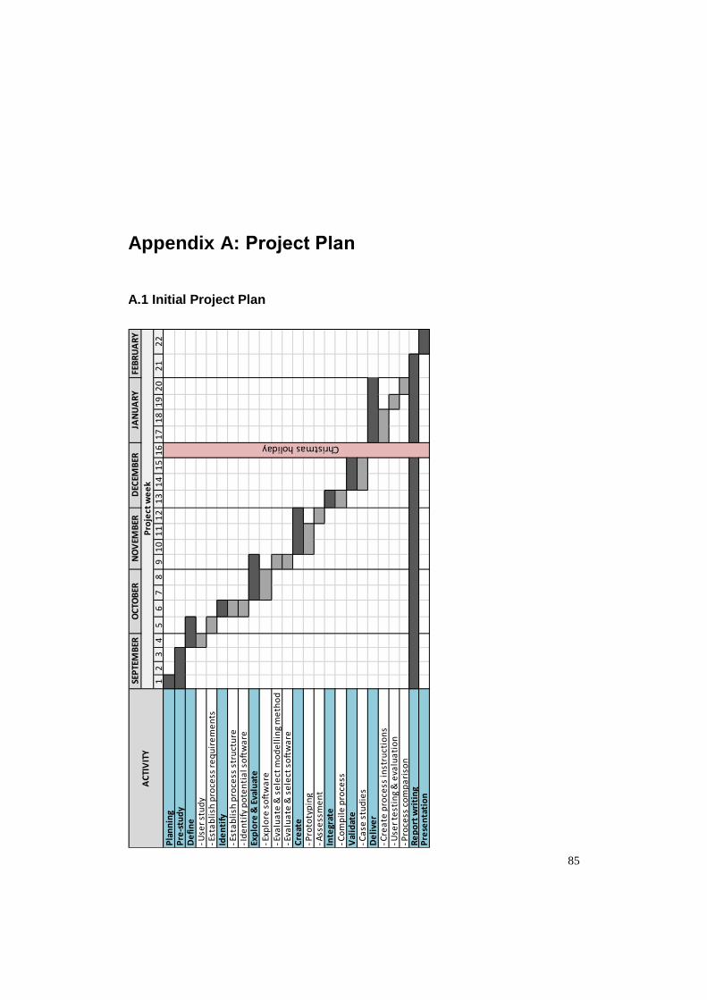
85
Appendix A: Project Plan
A.1 Initial Project Plan
12
34
56
78
91
01
11
21
31
41
51
61
71
81
92
02
12
2P
lan
nin
gP
re-s
tud
yD
efi
ne
Use
r st
ud
y E
sta
bli
sh p
roce
ss r
eq
uir
em
en
tsId
en
tify
Est
ab
lish
pro
cess
str
uct
ure
Id
en
tify
po
ten
tia
l so
ftw
are
Exp
lore
& E
valu
ate
Exp
lore
so
ftw
are
Eva
lua
te &
se
lect
mo
de
llin
g m
eth
od
Eva
lua
te &
se
lect
so
ftw
are
Cre
ate
Pro
toty
pin
g A
sse
ssm
en
tIn
tegr
ate
Co
mp
ile
pro
cess
Val
idat
e C
ase
stu
die
sD
eli
ver
Cre
ate
pro
cess
inst
ruct
ion
s U
ser
test
ing
& e
valu
ati
on
Pro
cess
co
mp
ari
son
Re
po
rt w
riti
ng
Pre
sen
tati
on
FEB
RU
AR
Y
Pro
ject
we
ek
Christmas holiday
AC
TIV
ITY
JAN
UA
RY
SEP
TEM
BER
OC
TOB
ERN
OV
EMB
ERD
ECEM
BER

Appendix A: Project Plan
86
A.2 Actual Project Plan
12
34
56
78
91
01
11
21
31
41
51
61
71
81
92
02
12
22
32
42
52
62
72
82
93
0P
lan
nin
gP
re-s
tud
yD
efi
ne
Use
r st
ud
y E
sta
bli
sh p
roce
ss r
eq
uir
em
en
tsId
en
tify
Est
ab
lish
pro
cess
str
uct
ure
Id
en
tify
po
ten
tia
l so
ftw
are
Exp
lore
& E
valu
ate
Exp
lore
so
ftw
are
Eva
lua
te &
se
lect
mo
de
llin
g m
eth
od
Eva
lua
te &
se
lect
so
ftw
are
Cre
ate
Pro
toty
pin
g A
sse
ssm
en
t I
tera
tio
nIn
tegr
ate
Co
mp
ile
pro
cess
Val
idat
e C
ase
stu
die
s, 1
st m
ee
tin
g P
rin
t so
cke
ts C
ase
stu
die
s, p
ati
en
t fi
ttin
gs E
xte
nsi
on
of c
ase
stu
dy
1, c
rea
te a
rm E
xte
nsi
on
of c
ase
stu
dy
1, p
ati
en
t fi
ttin
gD
eli
ver
Cre
ate
pro
cess
inst
ruct
ion
s P
roce
ss c
om
pa
riso
nR
ep
ort
wri
tin
gP
rese
nta
tio
n P
rep
ara
tio
ns
Fin
al p
rese
nta
tio
n
Christmas holiday
AP
RIL
Pro
ject
we
ek
FEB
RU
AR
YM
AR
CH
AC
TIV
ITY
SEP
TEM
BER
OC
TOB
ERN
OV
EMB
ERD
ECEM
BER
JAN
UA
RY

Appendix A: Project Plan
87
A.3 Comments to Time Deviations
The project ended up being eight weeks longer than initially anticipated. This was
mainly an effect of the extension of the first case study in the Validation phase, where
a complete cosmetic arm prosthesis integrated with a socket was designed and 3D
printed for the patient. This activity was not previously planned for but included
further on since it was considered relevant for the project as a whole. Moreover, the
Validation phase was further delayed due to difficulties to synchronise meeting time
and date between all parties involved.
The development phase Explore & Evaluate also required additional time in order to
get familiarised with the three software, distinguish alternative ways of modelling the
socket and integrating the electrodes and finally evaluate these to be able to select the
most suitable options. To be able to thoroughly learn all three identified software,
additional weeks would have been necessary. The knowledge gained during the
weeks already spent exploring the software was however considered sufficient to
perform a proper evaluation.
As a result of necessary iterations of the electrode attachment design, the Create
phase had to be extended. Furthermore, deciding to create both a booklet and video
tutorial as learning material, the Delivery phase required more time than accounted
for initially. The total amount of delays unfortunately lead to having to exclude the
activity of letting the user test and evaluate the complete process.


89
Appendix B: Ranking of Process Requirements
User needs categorised and converted into requirements that were ranked according to
average relative importance.
User Need Imp. Requirement Average imp. (Requirement)
Rank
The process is
adaptable.
4
Flexible 4 2 Possibility to create
different types of
sockets.
4
Ability to make detailed
changes. 4
Fewer steps to create
the socket. 4
Efficient 4 2 Shorter lead time of the
socket. 4
The process is easy to
manage. 4
Easy to learn and
manage 3.3 3
Process instructions are
presented both in
writing and practise. 3
3D technology and
software are easy to
learn.
3
Material is inexpensive. 3 Economical 3 4
Methods are gentle to
the patients.
4 Patient-friendly 4 2
The process can create a
product aligned with the
initial idea. 4
Effective 4.3 1 Ability to identify and
visualise the patient’s
anatomy. 4
The process is accurate. 5
The process is tidy. 3 Other 3 4


91
Appendix C: Evaluation Matrices
Concept screening matrix for evaluation and selection of modelling methods.
Criteria
Modelling Method
A1 (ref)
Adjustable Planes
A2 Scale
A3 Offset
A4 Scanned Socket
Ease of learning 0 + + +
Accuracy 0 0 + -
Adaptability 0 + + -
Efficiency 0 + + +
Adjustability 0 0 + -
Sum +’s 0 3 5 2
Sum 0’s 5 2 0 0
Sum –‘s 0 0 0 3
Net score 0 3 5 -1
Rank 3 2 1 4
Continue? NO NO YES NO
+ = Better than reference, 0 = Same as reference, - = Worse than reference
Concept scoring matrix for evaluation and selection of software. The weight
percentage was determined from the user’s previous rating of needs.
Criteria Weight
Software
Blender (reference)
Meshmixer Creo
Parametrics
Rating Weighted
Score Rating
Weighted Score
Rating Weighted
Score
Effective 23.2% 3 0.696 4 0.928 2 0.464
Flexible 21.4% 3 0.642 3 0.642 3 0.642
Efficient 21.4% 3 0.642 4 0.856 2 0.428
Easy to learn and manage
17.9% 3 0.537 5 0.895 2 0.358
Economical 16.1% 3 0.483 3 0.483 1 0.161
Total score 3 3.804 2.053
Rank 2 1 3
Continue? NO YES NO
1=Much worse than reference, 2=Worse than reference, 3=Same as reference, 4=Better than reference, 5=Much better than reference Blender is selected as overall reference. Reference point for each criterion has the rated value marked in bold.

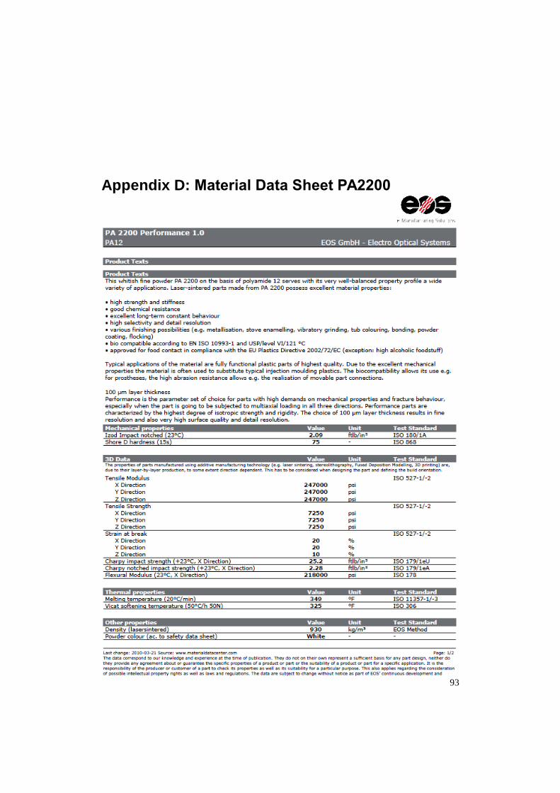
93
Appendix D: Material Data Sheet PA2200

Appendix D: Material Data Sheet PA2200
94

95
Appendix E: Booklet User Guide
The following pages of this appendix contains a version of the booklet user guide,
reformatted from the original booklet to suit this report.


The Perfect FitUser Guide
to creating custom-made transradial prosthetic
sockets by using 3D technology

Created by
Emelie Strömshed
as part of the final project in my master’s studies in mechanical engineering with industrial design at Lund University
2015/2016

Table of ContentsSTEP 1: Collect Patient Data
STEP 2: Repair Scan
STEP 3: Design Socket
STEP 4: Prepare for Printing
STEP 5: Print Socket
STEP 6: Post-Processing
STEP 7: Ready-To-Use Socket
1-2
3-4
5-12
13
14
15
16

STEP 1: Collect Patient Data
Explain the procedure.
Are there certain areas of the residual limb that need to be taken into consider-ation?
Position the residual limb in preferred angle.
Instruct the patient to hold the position while being scanned.
Condyles and olecranon.
Areas in need of additional pressure or pressure relief.
Shape of trimlines.
Electrode placement for a myoelectric socket.
Start the iSense application in the iPad.
Hold the scanner ≈40 cm from the residual limb and keep the limb centered on the screen. Zoom in/out to size the outlined box. Make sure it encloses the complete resid-ual limb.
Mark out with a water-soluble pen:
SCANNING BEST PRACTICELight should be distributed as equal as possible over the residual limb to enhance colours and reduce shadows.Position the patient and residual limb so that there is 360°-clearance, allowing you to scan from all angles.For the most accurate result, the residual limb should be as still as possible during the scanning session.Optimal distance range when scanning is 40-150 cm from the residual limb.
1
3
2
4
DIALOGUE WITH PATIENT
POSITION RESIDUAL LIMB
MARKINGS ON RESIDUAL LIMB
SCAN
1

STEP 1: Collect Patient Data Start scan .
Move the scanner slowly and steadily around the residual limb while watching the screen.
Use the Crop tool to drag a box around the part of the scan you want to keep. Tap Crop again to turn off the tool. If necessary, use the Erase tool to remove any unwanted, smaller portions of the scan by dragging your finger over them. Make sure not to erase parts that are important for the final fit of the socket. Tap Erase again to turn off the tool. Tap Solidify to fill in holes and make the scan solid. In the next stage of editing, use Auto Enchance if the scan needs increased brightness, clarity or contrast. It is important that the previously made markings are visible. If unwanted areas around the scanned residual limb still remain, use the Trim tool to slice these areas away by drawing a line with your finger. The smaller area will be re-moved. Tap Trim again to turn off the tool. When satisfied with editing, tap the right arrow to move on to saving. Tap to ensure the file format is set to OBJ. This format will allow saving the colour of the scan as well. Tap to save the scan to the iPad. Name the scan “patient’s name_scan number”.
NAVIGATION
Undo last change. Reset view to initial position & orientation. Return to start screen. Settings for the current work flow. Help menu.
AB
E
CD
Rotate Zoom Pan
When satisfied with the scan, tap the right arrow to finish and move on to editing.
When needed, tap to pause scan. Tap to resume.
Fill unwanted gaps in the scan by passing multple times or holding the scanner still over the gap.
2

Meshmixer Navigation & Handy Hotkeys
Tumble
Pan
Zoom
Select
Transform (object or selection) (move/scale/rotate)
Show Wireframe
Select All
Deselect
Cancel
Accept
Expand Selection
Invert Selection
Undo
Brush Size
Invert Brush Property
Show Object Browser
Redo
Strength
Alt + or
Alt + or Shift + or Alt + Shift +
Ctrl + Shift + O
Alt + or Alt + Ctrl +
Ctrl + Z
Ctrl +
Ctrl + Y
S
W
Ctrl + A
Ctrl +
Enter
I
T
(Selection & Sculpt mode)
(Sculpt mode)
(Sculpt mode)
Esc
E
NA
VIG
ATIO
NA
CTIO
NTO
OL
SELE
CTIO
NBR
USH
3

STEP 2: Repair Scan
2
1
4
IMPORT SCAN TO SOFTWARE
TRANSFER FILES TO COMPUTER
DIGITAL CLEAN-UP
3INSPECT SCAN
Start Meshmixer.
Click Import to find and import the scan of the resid-ual limb to the software.
Click Analysis Inspector to check the scan for any incom-plete sections. pink sphere = disconnected blue sphere = hole red sphere = non-manifold edges
If incomplete sections appear, first try running the Auto Re-pair All function.
If the auto repair leaves an unsatisfying result, then manually fix the sections by right-clicking the spheres one by one.
Run the Inspector again until no incomplete sections remain.
Click Done to leave the tool.
Connect the iPad to a computer.
Open iTunes and click the Apps tab iSense.
Select the file(s) under iSense Documents and click Save to.
Select which folder on the computer you want to transfer the file(s) to.
4

STEP 3: Design Socket
1ADJUST PRESSURE POINTS AND TRIMLINES
Duplicate the scan of the residual limb, using the Object Browser window. If the window is not visible press Ctrl + Shift + O.
Hide the created copy and keep it for reference if needed when making the adjustments.
Click Sculpt.
Expand the Brushes menu and choose a suitable brush to add/remove material on the scan according to the markings. If no original colours are showing on the scan, click Shaders Drag & drop the globe onto the scan.Recommended brushes are the BubbleSmooth brush and the Inflate brush.
Alternate between the brush types and experiment with Size and Strength of the brush depending on the amount of ma-terial that needs to be added/removed.
Use to add material and Ctrl + to remove.
If necessary, alternate between the grey and the globe shad-er in order to better see how the surface changes as you are making the adjustments.
Finish sculpting by refining the surface using the BubbleSmooth brush with a low strength (≈6-9). Smoothen the sur-face without distorting the adjustments you have just made.
Press S to activate the Select tool.
Click the scan and press Ctrl + A to select the whole part. It should now be completely orange.
Hide/Show Object
Duplicate Delete
TIPS WHILE MODELLINGMake sure there is always a copy of the original scan and, further ahead, the adjusted scan in the Object Browser. It is very helpful to keep them as reference while modelling.In order to have a good overview of all the parts in the Object Browser, rename them by double clicking the name. Save often, especially after finishing each substep.
For a plain socket intended for a passive prosthesis, follow substeps 1-4. For a myoelectric socket, add substeps 5 & 6 and for a patterned socket, add substep 7.
5

5
2OFFSET ADJUSTED SCAN
Duplicate the adjusted scan twice and Hide the created copies.
Use the brush to select the areas to be used for the socket.
Click Modify Smooth Boundary or press B to im-prove the shape of the selected trimline.
In the tool, drag the handles to increase the values until a desired shape is reached Accept.
While still in the Select tool, click Edit Offset or Ctrl + D.
In the Distance box, type in the desired socket thickness. Press Tab to update. Child: 1-1.5 mm Adult: 1.5-2 mm Patterned socket child/adult: 0.7-1 mm
Increase Accuracy slightly.
Make sure the boxes Connected and Pre-serve Groups are checked.
Click Accept followed by Esc to leave the Select tool.
Press W to show the wireframe.
Press R to start the Remesh tool.
Set the Remesh Mode to Relative Density.
Reduce the mesh density to in between -10 and -30 %. Make sure there is no noticeable change in the shape of the adjusted scan, but that the mesh density is evenly distributed over the socket surface.
When satisfied with the result, click Accept followed by Esc to leave the Select tool.
Press W to hide the wireframe.
6

3HOLLOW SOCKET
Show one of the previously made copies of the adjusted scan.
Activate the offsetted scan either by clicking directly on the part or on its name in the Object Browser list.
Hold Ctrl while also clicking on the now visible copy of the adjust-ed scan in the Object Browser.
A new menu will appear. Click Boolean Difference to subtract the adjusted scan, creating the hollow socket.
Click Accept.
Zoom in on the trimline.
Press S to activate the Select tool.
Reduce the brush size and double-click on the trim-line edge.
Hold & drag to expand the selection further.
Click Deform Smooth.
Drag the handles in the tool to experiment with the trimline shape. When a desired shape is reached Accept.
4COMPLEMENTARY SHAPING & SMOOTHING
7

If necessary, continue shaping the trimlines using the Sculpt tool.
Press S to activate the Select tool.
Double-click on the outer and the inner surface of the socket to select them both.
Click Deform Smooth to smoothen the surfaces.
> For a plain socket intended for a passive prosthesis, the step of designing the socket is now completed. Proceed to Step 4: Prepare for Printing, p. 13.
> To create a myoelectric socket, continue with substeps 5 & 6, pp. 8-11.
> To apply a pattern to the socket, add substep 7, pp. 11-12
Click Import to add the electrode module to the current modelling scene.
Hold Shift and click on the attachment and the electrode dummy to activate them both.
Press T to start the Transform tool.
Drag the arrows to move/rotate the complete electrode module as necessary, placing it on the outer surface of the socket. Only the bottom surface of the electrode dummy should be visible from the inside of the socket with a pro-trusion of ≈1 mm.
When satisfied with the placement, click Accept.
With the attachment and dummy still activated, click Dupli-cate in the Object Browser to create a copy of them both.
Press T to start the Transform tool and continue by placing the electrode module on the opposite side of the socket, using the same manner as when placing the first one.
5IMPORT & PLACE ELECTRODE MODULES
NOTE! The curvature of the socket can in some cases result in the flat bottom surface of the attachment not providing full contact with the outside of the socket, leaving a small gap. In this case, perform the following tasks (marked ) before continuing the regular procedure:
8

Place the two modules so that the lower surface of the electrode dummies are visible from the inside of the socket with a protrusion of ≈1 mm. Some areas of the attachment itself might also protrude slightly on the inside.
Click one of the attachment to activate it.
Temporarily hide the socket in the Object Browser.
Press S to start the Select tool.
Double-click the flat bottom surface of the attachment so it turns orange.
Press D to start the Extrude tool.
Show the recently hidden socket.
Drag the handle, or type in a value large enough to close the gap between the attachmentand the outer surface of the socket. Zoom in to make sure the two parts fully intersect.
Repeat the procedure for the second attachment.
Click the socket to activate it.
Duplicate the socket to create a copy.
Hide the original socket.
Press S to start the Select tool.
Double-click the inner surface of the socket copy and press Ctrl + D to start the Offset tool.
Adjust the distance value until the attachments are no longer visible on the inside of the socket.
Click Accept followed by Esc to leave the Select tool.
Duplicate the thickened socket that was just created.
Activate one of the attachments by clicking on it.
Hold Ctrl while also clicking one of the two thickened socketsin the Object Browser.
In the menu that appears, click Boolean Difference to remove material from the bottom of the attachment creating a curvature according to the socket shape.
Repeat the Boolean Difference procedure, using the second attachment and the remaining copy of the thickened socket.
9

The bottom surfaces of the attachments are now completely aligned with the outer surface of the socket. To be 3D-printable, however, the parts need to be intersected and merged.
Show the original socket, which is now intersected with both attachments.
Click one of the attachment to activate it. Press S to start the Select tool.
Double-click the curved bottom surface of the attachment so it turns orange.
Press D to start the Extrude tool.
Set the value to 0.8 mm and click Accept.
Repeat the procedure for the second attachment.
Click to activate one of the attachments.
Hold Ctrl while also clicking the original socket in the Object Browser or Shift while clicking directly on the part in the modelling scene. In the menu that appears, click Boolean Union to join the socket and the attachment into one part.
Repeat the procedure to join the second attach-ment to the socket as well.
Press S to activate the Select tool.
Double-click the outer surfaces of the socket. Make sure all of it is selected, including the two attachments.
Click Deform Smooth.
Click Accept followed by Esc to leave the Select tool.
> To create a myoelectric socket with an added pattern, proceed to substep 7, p. 11.
10

6SUBTRACT ELECTRODES
7ADD PATTERN
Click to activate the socket.
Hold Shift while clicking one of the two electrode dummies.
In the menu that appears, click Boolean Difference to sub-tract the electrode dummy, creating a cavity all the way through the attachment and the socket wall.
Repeat the procedure using the second electrode dummy.
Press S to start the Select tool.
Double-click or use the brush to select the entire outer surface of the socket.
Press Ctrl + D to start the Offset tool.
Set the distance value to ≈0.2 mm and make sure the Connected box is unchecked. This creates a surface 0.2 mm from the original socket.
Click Accept.
With the surface still selected, click Edit Separate or press Y to make the created surface and the socket into separate parts in the Object Browser.
Press S to start the Select tool.
Select the entire surface that was just created.
Press W to show the wireframe.
Press R to start the Remesh tool.
> For a myoelectric socket, the step of designing the socket is now completed. Proceed to Step 4: Prepare for Printing, p. 13.
11

Reduce the mesh density to -50 % Accept.
With the surface still selected, press R to start the Remesh tool again.
Reduce the mesh density to -50 % Accept. Repeat if necessary until a mesh size similar to the image is achieved. A larger sized mesh will generate a less dense pattern.
Press W to hide the wireframe and Esc to leave the Select tool.
Click Edit Make Pattern.
In the menu that appears, choose desired Pattern Type and experiment with the values for Element Dimension and Element Spacing until a desired result is achieved. 1-1.5 mm as Element Dimension is recommended.
Click Accept to create the pattern.
Click to activate the pattern.
Hold Shift while also clicking the original socket. If it is currently hidden, show it by clicking the eye in the Object Browser.
For best results, choose Solid Type - Accurate and maximum value for both Solid Accuracy and Mesh Density.
Click Update followed by Accept to perform the operation.
In the menu that appears, click Combine to make the pattern and the socket into one part.
Click Edit Make Solid to create a water-tight model, suitable for 3D printing.
> For a patterned socket intended for a passive prosthesis, the step of designing the socket is now completed. Proceed to Step 4: Prepare for Printing, p. 13.
> For a myoelectric socket with an added pattern, the electrodes can now be subtracted as described in the previous substep 6, p. 11.
12

STEP 4: Prepare for Printing
1
2
3
INSPECT MODEL
CORRECT IMPERFECTIONS
EXPORT AS STL
Click Analysis Inspector to check the model for any incomplete sections. pink sphere = disconnected blue sphere = hole red sphere = non-manifold edges
If incomplete sections appear, first try running the Auto Repair All.
If the auto repair leaves an unsatisfying result, then manually fix the sections by right-clicking the spheres one by one.
Run the Inspector again until no incomplete sections remain.
Click Done to leave the tool.
Click File Export or press Ctrl + E.
In the Export Mesh dialogue box that appears, set the file format to STL Binary Format (*.stl)
Name the file and place it in desired folder.
Click Save.
13

STEP 4: Prepare for Printing STEP 5: Print Socket
1
2
SEND STL-FILE
E-mail or upload the STL-file to the chosen 3D printing service.
All activities involving the printing procedure are handled by the 3D printing service.
Depending on the choice of printing service, the finished socket can either be shipped to the customer or collected by the customer at the printing service.
14

STEP 6: Post-Processing
1
3
2
INSPECT SOCKET
SMOOTHEN SURFACES
REMOVE EXCESS MATERIAL
Inspect the printed socket to identify areas in need of refinement.
Where necessary, use a fine-grit sandpaper (800-1000) to smoothen surfaces of the socket. Be particularly thorough with areas that will be in direct contact with the patient’s skin.
Depending on the chosen 3D printing method, excess material may need to be removed. For the SLS technology that uses powdered material, excess powder is much likely to have accumulated in the holes created for the electrodes in a myoelectric socket. Remove this powder by using a needle, a metal wire or any object small enough to fit in the hole, preferably with a slightly bent shape for better accessibility.
15

STEP 6: Post-Processing
15
1
3
2
INSERT ELECTRODES
FIT ADJUSTMENTS
PATIENT FITTING
Hereafter, the finished socket can be used in the further work of completing the entire prosthesis for the patient.
For a myoelectric socket, insert the two electrodes in the attachments on the socket.
If necessary, use a heat gun or sandpaper to to make smaller fit adjustments to the socket.
Try the socket fit on the patient.
For a myoelectric socket, perform a myo-test to get an indication of the level of contact between the electrodes and the patient’s residual limb.
STEP 7: Ready-To-Use Socket
16
