the mechanical design portfolio sam …samgoldberg.com/pdfs/sam-goldberg-portfolio.pdf · apparatus...
TRANSCRIPT

The MECHANICAL DESIGN PORTFOLIO of SAM GOLDBERG
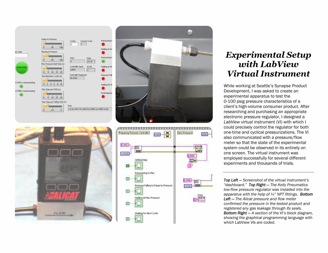
Experimental Setup
with LabView Virtual Instrument
While working at Seattle’s Synapse Product
Development, I was asked to create an
experimental apparatus to test the
0-100 psig pressure characteristics of a
client’s high-volume consumer product. After
researching and purchasing an appropriate
electronic pressure regulator, I designed a
LabView virtual instrument (VI) with which I
could precisely control the regulator for both
one-time and cyclical pressurizations. The VI
also communicated with a pressure/flow
meter so that the state of the experimental
system could be observed in its entirety on
one screen. The virtual instrument was
employed successfully for several different
experiments and thousands of trials.
Top Left — Screenshot of the virtual instrument’s
“dashboard.” Top Right — The Kelly Pneumatics
low-flow pressure regulator was installed into the
apparatus with the help of ¼” NPT fittings. Bottom
Left — The Alicat pressure and flow meter
confirmed the pressure in the tested product and
registered any gas leakage through its seals.
Bottom Right — A section of the VI’s block diagram,
showing the graphical programming language with
which LabView VIs are coded.

Formula SAE Brake Pedal
I engineered this brake pedal assembly for
use on the 2012 University of Washington
Formula Motorsports race car. After
interviewing the team’s drivers and brake
engineer for their preferences, I wrote a multi-
hundred line-long MATLAB script to analyze
resultant force vectors and to optimize the
pedal’s geometry. Using ANSYS Workbench, I
developed and built two iterations of a safe
and lightweight design that could withstand
450lb of force with a minimum factor of safety
of 2.0. The race-ready second iteration was
constructed using water jet-cut 6061-T6
aluminum and machined brass and 7050-
T4571 aluminum. With military-grade
fasteners, it weighs just 1.13lb.
Top Left — Two views of the 3D SolidWorks pedal
model. The left view includes the hydraulic master
cylinders that actuate the brake rotors when the
pedal is depressed. Top Right — An ANSYS
Workbench model of the strain induced during one
of the three separate worst-case loading
scenarios. Bottom Left — The final version of the
brake pedal (left) was built upon the successes
and failures of its first iteration (right). Bottom
Right — Brass bushings were press fit to the
bracket and pedal after each was cut on a three-
axis CNC mill with Siemens NX.

Formula SAE Brake Pedal
Design Intent
This lightweight, easy-to-manufacture foot
contact surface was cut with a water jet from
6061-T6 aluminum. Bent gussets add strength.
I-beam-like design allows the pedal to be both
strong and low-mass. The thin member opposes
hydraulic master cylinder forces in tension.
The pedal was designed around the master
cylinder bracket and assembly. Multiple hole
locations enable the bracket position to be
adjusted for ideal driver-over-master cylinder
mechanical advantage.
Weight reduction slots stop briefly to allow
pedal surface gussets to meet a flat surface. The multi-slot hinge and internal bushings
eliminate lateral slop when depressing the pedal.
The lowered step forward of the hinge stops
the pedal from rotating too far and shearing off the
master cylinders’ hydraulic fittings.
The “heel well” has two functions. First, it
captures the driver’s heel, keeping his or her foot
in place during high-G maneuvers. Second, it
advantageously redistributes internal stresses to
the bracket’s rear chassis connection bolt.
Like the brake pedal surface, the kill switch
bracket is water jet-cut. Simple bent gussets
strengthen the kill switch bracket and prevent it
from rotating with respect to its attachment bolt.
Brass spacers keep the master cylinders
rotating in-plane, while the support arms prevent
nearby wiring from interfering with rotation.

Formula SAE
Throttle Pedal
This throttle pedal assembly was engineered
for use on the 2012 University of Washington
Formula Motorsports race car. For safety, the
pedal connects to the engine throttle via two
(rather than one) bicycle shifter cables. With
military-grade fasteners, it weighs less than a
pound.
Top Left — Two views of the 3D SolidWorks throttle
pedal model. Top Right — UW Formula
Motorsports racer competing at FSAE German,
where it finished 14th overall. Bottom Left — The
brake pedal and throttle pedal in situ. The brown
pole in the middle of the photo is the steering
column. Bottom Right — An ANSYS Workbench
analysis of the worst case stress scenario for the
first iteration of the 4130 steel throttle bracket.

Formula SAE Throttle Pedal
Design Intent
This lightweight, easy-to-manufacture foot
contact surface was cut with a water jet from
6061-T6 aluminum. Bent gussets add strength
and help retain the driver’s foot during high-G
maneuvers.
Weight-saving grooves stop briefly for the
surface attachment screws to mount and to allow
a surface to for the stop screw to contact.
Holes on the pedal—along with cable
tensioners—allow the team to position the throttle
cables for just the right amount of pedal travel.
The easily adjusted and locked stop screw
prevents the pedal from over-rotating. This V-shaped bent steel bracket keeps the
cable ferrules and cables pointing precisely at the
cable connection points on the pedal.
The aluminum heel cup keeps the driver’s foot
locked in place, and along with an unseen tension
spring helps the driver return the pedal to the
“throttle closed” position.
Lightweight chassis bracket comprises two
pieces of 4043 steel that are welded together.
Nylon bumpers stop the pedal from over-
rotating past the throttle-closed position, without
damaging the chassis bracket.

Fishing Vessel Evacuation Device
Our team’s senior capstone project sponsor
asked us to investigate if life rafts used by the
fishing industry could be improved. After
extensive interviews with rescue swimmers,
fishing captains, survival trainers, and others,
we found that what was actually needed is a
device to prevent evacuees from being swept
away by wind, waves, and currents as they
swim from distressed vessels to their life rafts.
As the team manager, I led our team through
the quarter-long design process. After my
“claw” design won an internal design
competition, I machined a proof-of-concept
device that we tested in a diving pool.
How it works: Before entering the water,
evacuees insert the painter line (a rope
connecting the distressed vessel to the life
raft) into the claw device. During the jump,
evacuees use one hand to secure the seat
between their legs. A webbed safety lanyard
connects the claw to the seat and limits
deceleration shock. Upon surfacing, the
evacuee discards the seat and uses the claw
to traverse the painter line to the life raft.
Top Left — A 3D SolidWorks model of the “claw”
concept. Top Right, Bottom Left — The proof-of-
concept device used dynamic climbing line to
connect a plywood disc seat to the claw. A
commercially available cam cleat controlled the
painter line. Bottom Right — A team member
traverses the painter line during pool testing.

Fishing Vessel
Evacuation Device
Design Intent
Once in the water, evacuees can use this
handle to slide the device along the painter line.
By doing so, evacuees can traverse the painter line
more easily toward the life raft.
The cam cleats allow for passage along the
painter line in only one direction—toward the life
raft. The cleats lock up when the device attempts
to move back toward the vessel, but do so without
harming the painter line.
Elastic cords keep the lynchpin retracted in
position. The corrosive marine environment makes
elastic preferable to steel springs.
The aluminum lynchpin extends well beyond
the cleat box so that evacuees in gloved
immersion suits may easily grasp it. At the same
time, the lynchpin penetrates only slightly past the
painter line slot to cut down on the amount of
lynchpin travel needed to open the slot.
The lynchpin opens perpendicularly to the
direction of travel so that forces exerted by the
painter line do not unpin it. The prongs are set low
to the fore and aft of the cleat to keep the painter
line moving in the plane of the cleat and to prevent
an untaught painter line from bowing above the
cleat.
This hole serves as a mounting point for the
webbed safety lanyard that connects the claw to
the seat.
Lightweight, high-strength plastic keeps the
device buoyant. High-contrast orange color allows
for quick detection in dark sea water.
The painter line
Toward the
life raft

Balsa Car Chassis
What a fun project! Could a team of
engineering design students create a balsa
car chassis that would protect an imaginary
family from a crushing force? Most teams
strove to build the strongest frame possible.
Our team took a different approach: barely
fulfilling the requirements through a series of
clever cheats. Our quarter-pound chassis
withstood 285 lbs. of force, saving our make-
believe occupants and producing a class-
leading 995:1 strength-to-weight ratio. Visit
www.samgoldberg.com to watch a video of
the frame being crushed… And yes, I know it
looks nothing like a car.
Top Left — Our three-sled-blade design was meant
to use as little balsa as possible. We hung the
cube-like passenger cabin so as to prevent it from
ever seeing crushing forces. Top Right — The
agony and the ecstasy of watching success in
action. Bottom Left — No matter what level of
force transmitted through the sled blades, none
reaches the passenger cabin. Bottom Right — The
short post extending from the top of the passenger
cabin and the toothpick windshield and hood
beams fulfill dimensional requirements without
providing any structural support.
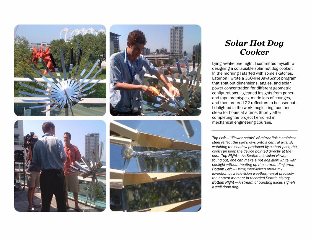
Solar Hot Dog Cooker
Lying awake one night, I committed myself to
designing a collapsible solar hot dog cooker.
In the morning I started with some sketches.
Later on I wrote a 350-line JavaScript program
that spat out dimensions, angles, and solar
power concentration for different geometric
configurations. I gleaned insights from paper-
and-tape prototypes, made lots of changes,
and then ordered 22 reflectors to be laser-cut.
I delighted in the work, neglecting food and
sleep for hours at a time. Shortly after
completing the project I enrolled in
mechanical engineering courses.
Top Left — “Flower petals” of mirror-finish stainless
steel reflect the sun’s rays onto a central axis. By
watching the shadow produced by a short post, the
cook can keep the device pointed directly at the
sun. Top Right — As Seattle television viewers
found out, one can make a hot dog glow white with
sunlight without heating up the surrounding area.
Bottom Left — Being interviewed about my
invention by a television weatherman at precisely
the hottest moment in recorded Seattle history.
Bottom Right — A stream of bursting juices signals
a well-done dog.

Bonus: INTERACTIVE EXHIBIT DESIGN for Pacific Science Center
The process of developing interactive exhibits is similar to that of
designing mechanical devices. Each begins with a client’s wild idea.
Research and conversation distill a focus and a strategy. Concepts
are turned into models, and prototypes are tested so that developers
can work through technical and resetting issues. Finally, a device
emerges that is built durable enough to withstand anything a seven-
year-old might contemplate doing to it.

The Wellbody Academy
Wondermine’s Ken Burns and I conceived The
Wellbody Academy to be an entirely new
breed of exhibition. Much more than a tired ol’
demonstration of physiology, the exhibition
immerses visitors in a mythical school where
they can explore how their lifestyles affect
their wellbeing. In addition to leading a team
that developed over 30 interactive devices, I
wrote every word in the fundraising book that
helped raise $7 million for construction. The
6,000 sq. ft. exhibition opened in late 2012.
Top Left — The Sneeze Wall’s spray of fine mist
convinces visitors to sneeze into their sleeves. Top
Center — Conceptual drawing of Professor
Wellbody and his academy. Top Right — With a
Little Help from My Friends reveals how teamwork
can reinforce wellness goals. Middle Left —
Conceptual drawing of the exhibition’s physical
activities. Middle Center — The Sleepability System
Maximizer clues visitors in to some of the most
common obstacles to a good night’s sleep. Middle
Right — This fast food drive-thru window allows for
role play about choosing better food options.
Bottom Left — In the Cafedium, visitors can
analyze a conveyor belt of different foods and build
a day’s worth of healthful meals. Bottom Center —
The Sleep Machine explains hour-by-hour what
happens inside a sleeping body. Bottom Right —
Gross! This interactive device projects an open
wound onto a visitor’s forearm to simulate the
area affected by poor periodontal health.
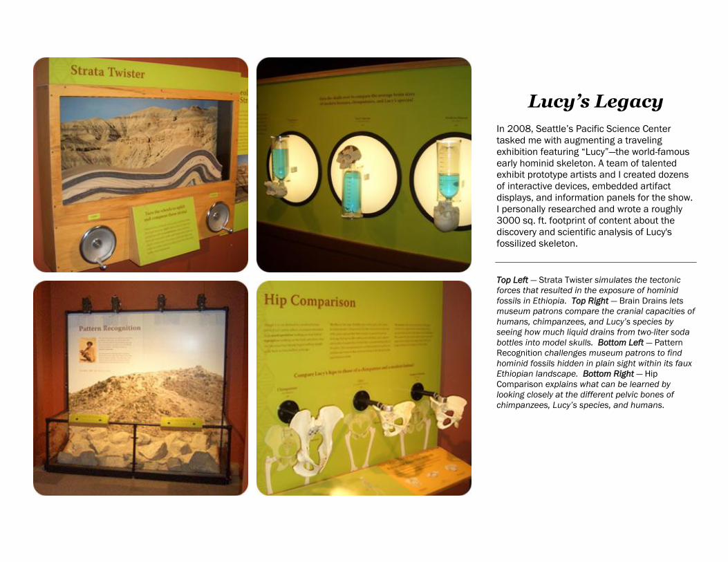
Lucy’s Legacy
In 2008, Seattle’s Pacific Science Center
tasked me with augmenting a traveling
exhibition featuring “Lucy”—the world-famous
early hominid skeleton. A team of talented
exhibit prototype artists and I created dozens
of interactive devices, embedded artifact
displays, and information panels for the show.
I personally researched and wrote a roughly
3000 sq. ft. footprint of content about the
discovery and scientific analysis of Lucy's
fossilized skeleton.
Top Left — Strata Twister simulates the tectonic
forces that resulted in the exposure of hominid
fossils in Ethiopia. Top Right — Brain Drains lets
museum patrons compare the cranial capacities of
humans, chimpanzees, and Lucy’s species by
seeing how much liquid drains from two-liter soda
bottles into model skulls. Bottom Left — Pattern
Recognition challenges museum patrons to find
hominid fossils hidden in plain sight within its faux
Ethiopian landscape. Bottom Right — Hip
Comparison explains what can be learned by
looking closely at the different pelvic bones of
chimpanzees, Lucy’s species, and humans.

Harvesting Science “Cosechando la Ciencia”
Pacific Science Center partnered with MESA to
produce this popular bilingual exhibition
meant for Washington’s farming communities.
Its 15 interactive devices help agriculture
workers talk to their children about the
everyday science and engineering involved in
their work. I researched, developed, and wrote
copy for each of the devices and helped
ensure that each could collapse into a box or
suitcase for easy storage. Two copies of the
exhibition travel on vans to fairs, festivals, and
schools throughout the state.
Top Left — Kids love using Pump It Up’s hand-
cranked wind turbine to deliver well water to
livestock. Top Right — Splice of Life shows how
viticulturists graft grapevines onto stumps of
different grape species. Bottom Left — Pick up this
'manure clump' to see which parasites are
infecting your horse. Bottom Right — Some of
Harvesting Science’s 15 interactive devices.

Washington State Science at Work
The sequel to Harvesting Science, this
Spanish-English bilingual exhibition highlights
some of Washington’s most important STEM
fields, including aerospace, seismology,
fisheries science, and hydroelectricity. I
researched and helped to develop the
concepts and prototypes that were later
turned into the collapsible interactive devices
and posters this make up this traveling show.
Top Left — Test you salmon identification skills with
Which Fish. Top Right — Washington is known for
its many bridges. Try your hand at piecing together
two different types: a cable bridge (above) and a
truss bridge (below). Bottom Left — Balancing Act
teaches why wings are placed where they are on
Washington's biggest exports—airplanes. Bottom
Right — Can you design an earthquake-safe
building? Engineer a structure and try shaking it to
the ground with Shake, Rattle & Roll.