the mac motor ac-servo motor with integrated driver mac50 ... · ac-servo motor with integrated...
TRANSCRIPT
�
The MAC motor®.AC-servo motor withIntegrated driverMAC50, 95, 140 and 141
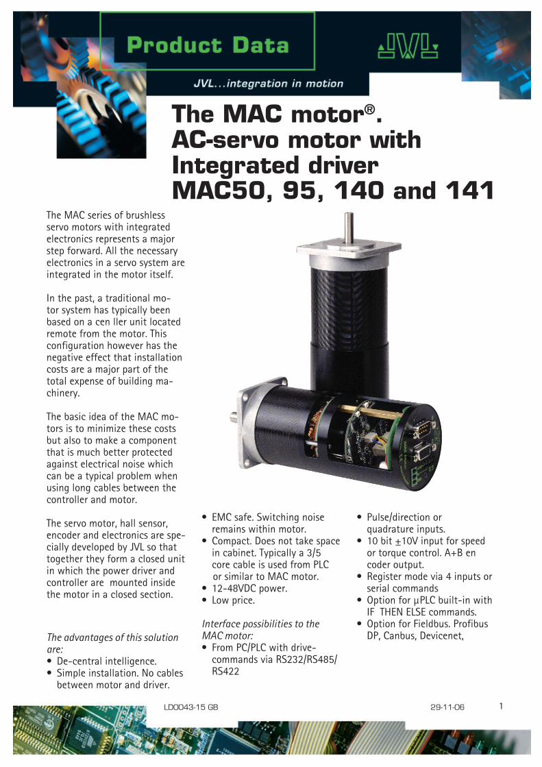
The MAC series of brushless servo motors with integrated electronics represents a major step forward. All the necessary electronics in a servo system are integrated in the motor itself.
In the past, a traditional mo-tor system has typically been based on a cen ller unit located remote from the motor. This configuration however has the negative effect that installation costs are a major part of the total expense of building ma-chinery.
The basic idea of the MAC mo-tors is to minimize these costs but also to make a component that is much better protected against electrical noise which can be a typical problem when using long cables between the controller and motor.
The servo motor, hall sensor, encoder and electronics are spe-cially developed by JVL so that together they form a closed unit in which the power driver and controller are mounted inside the motor in a closed section.
The advantages of this solution are:• De-central intelligence. • Simple installation. No cables between motor and driver.
• Pulse/direction or quadrature inputs. • �0 bit ±�0V input for speed or torque control. A+B en coder output.• Register mode via 4 inputs or serial commands• Option for µPLC built-in with IF THEN ELSE commands.• Option for Fieldbus. Profibus DP, Canbus, Devicenet,
LD0043-15 GB 29-11-06
• EMC safe. Switching noise remains within motor. • Compact. Does not take space in cabinet. Typically a 3/5 core cable is used from PLC or similar to MAC motor.• �2-48VDC power. • Low price.
Interface possibilities to the MAC motor: • From PC/PLC with drive- commands via RS232/RS485/ RS422
2
The MAC motor can be con-trolled with ±�0V for speed or torque control with encoder feedback to one master motion controller.
Furthermore the MAC motor can replace an arbitrary step or ser-vo system, being based on pulse and direction signals. There is a built-in electronic gear so that the MAC motor can simulate all possible step resolutions.
The MAC motor can thus replace all step- and servo-systems without change in the PLC/PC/controller software. Adaptation/replacement of existing step motor/servo systems can there-fore be achieved quickly.
Parameters are set up via the RS232 port from a Windows program.The supply voltage is 24VDC which is industry standard.
The motor can be delivered in 3 models: 46, 92 or �34W. A NEMA23 flange is standard so that the MAC motor can replace a step motor directly without mechanical changes.
The connector can be chosen as DSUB, Phoenix connector, Mili-tary plug or cable out. Backlash free and planetary gears in ratios of 3, 5, �0, 20, �00 can be delivered from stock.
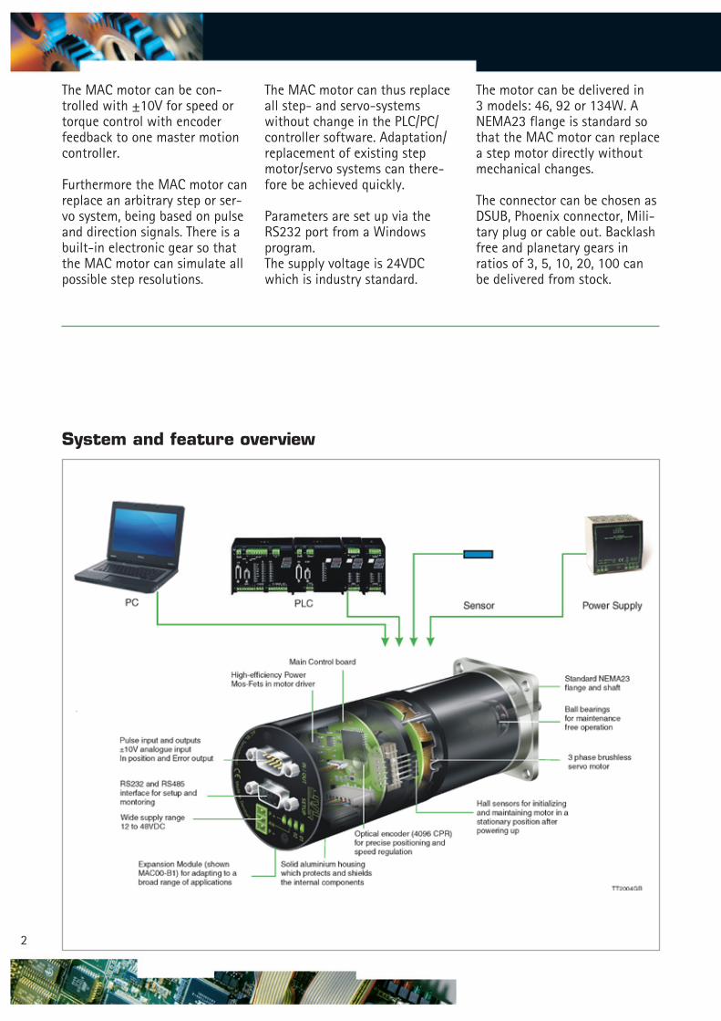
System and feature overview
3
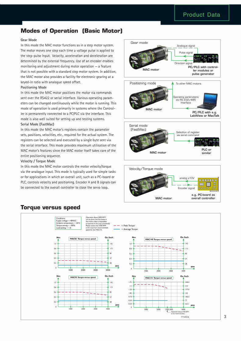
Modes of Operation (Basic Motor)Gear ModeIn this mode the MAC motor functions as in a step motor system. The motor moves one step each time a voltage pulse is applied to the step-pulse input. Velocity, acceleration and deceleration are determined by the external frequency. Use of an encoder enables monitoring and adjustment during motor operation — a feature that is not possible with a standard step motor system. In addition, the MAC motor also provides a facility for electronic gearing at a keyed-in ratio with analogue speed offset.Positioning ModeIn this mode the MAC motor positions the motor via commands sent over the RS422 or serial interface. Various operating param-eters can be changed continuously while the motor is running. This mode of operation is used primarily in systems where the Control-ler is permanently connected to a PC/PLC via the interface. This mode is also well suited for setting up and testing systems.Serial Mode (FastMac)In this mode the MAC motor’s registers contain the parameter sets, positions, velocities, etc., required for the actual system. The registers can be selected and executed by a single byte sent via the serial interface. This mode provides maximum utilisation of the MAC motor’s features since the MAC motor itself takes care of the entire positioning sequence.Velocity / Torque ModeIn this mode the MAC motor controls the motor velocity/torque via the analogue input. This mode is typically used for simple tasks or for applications in which an overall unit, such as a PC-board or PLC, controls velocity and positioning. Encoder A and B signals can be connected to the overall controller to close the servo loop.
Pulse signal
MAC motor PC/PLC with control-
ler modules or pulse generator
Operating parameters via RS 232/485
Interface
Selection of register via serial command
MAC motor
analog ±10V
MAC motor e.g. PC-board as overall controller
Direction signal
PC/PLC with e.g. LabWiew or MacTalk
MAC motor
PLC or similar
Gear mode
Positioning mode
Serial mode (FastMac)
Encoder signal
Analogue signal
To other MAC motors
Velocity/Torque mode
Torque versus speed
TT2005GB
= Peak Torque
= Average Torque
Operation above 4000 RPMcan be done, but the losses inthe motor make it impossibleto operate in this area continouslyPlease notice that 2700 RPM is the maximum recommendedspeed for the MAC141.
Conditions:Supply voltage = 48VDCAmbient temperature = 20°CTorque setting = 100%Load setting = 1.0
Nm Oz./Inch
Oz./InchNm
1000
1000
1.0 142
1421.0
0.8 113
1130.8
0.6 85
850.6
0.4 57
570.4
0.2 28
280.2
0
0
2000
2000
3000
3000
4000
4000
RPM
RPM
MAC50 Torque versus speed
MAC95 Torque versus speed
Oz./Inch
Oz./Inch
Nm
Nm
1000
1000
142
248.5
1.0
1.75
113
213
0.8
85
177.5
142
0.6
57
106.5
71
0.4
28
35.5
0.2
0
0
2000
2000
3000
30002700Operation above 2700 RPMis not recommended.
4000
4000
RPM
RPM
MAC140 Torque versus speed
MAC141 Torque versus speed
4
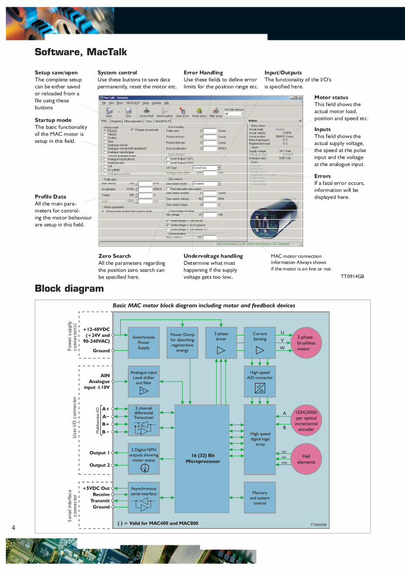
Software, MacTalk
Block diagram
3-phasebrushlessmotor
1024(2000)ppr optical incremental
encoder
Hall elements
+12-48VDC(+24V and
90-240VAC)
Ground
AINAnalogue
input ±10V
A+
A
B+
B
Output 1
Output 2
TransmitGround
( ) = Valid for MAC400 and MAC800
Receive+5VDC Out
SwitchmodePowerSupply
Power Dumpfor absorbingregenerative
energy
3-phasedriver
Current Sensing
High speedA/D converter
High speeddigital logic
array
Analogue inputLevel shifter
and filter
2 channeldifferentialTransceiver
Asynchronousserial interface Memory
and systemcontrol
2 Digital NPNoutputs showing
motor status16 (32) Bit
Microprocessor
A
HU
HV
B
W
V
U
HW
Pow
er s
uppl
yco
nnec
tor(
s)U
ser
I/O c
onne
ctor
Ser
ial i
nter
face
conn
ecto
r
Basic MAC motor block diagram including motor and feedback devices
TT2002GB
Startup modeThe basic functionalityof the MAC motor issetup in this field.
Setup save/openThe complete setupcan be either savedor reloaded from afile using thesebuttons
System controlUse these buttons to save datapermanently, reset the motor etc.
Error HandlingUse these fields to define errorlimits for the position range etc.
Input/OutputsThe functionality of the I/O'sis specified here.
Motor statusThis field shows theactual motor load,position and speed etc.
ErrorsIf a fatal error occurs,information will be displayed here.Profile Data
All the main para-meters for control-ing the motor behaviourare setup in this field.
Zero SearchAll the parameters regardingthe position zero search canbe specified here.
Undervoltage handlingDetermine what must happening if the supplyvoltage gets too low..
MAC motor connectioninformation Always showsif the motor is on line or not.
InputsThis field shows theactual supply voltage,the speed at the pulseinput and the voltageat the analogue input.
TT0914GB
5
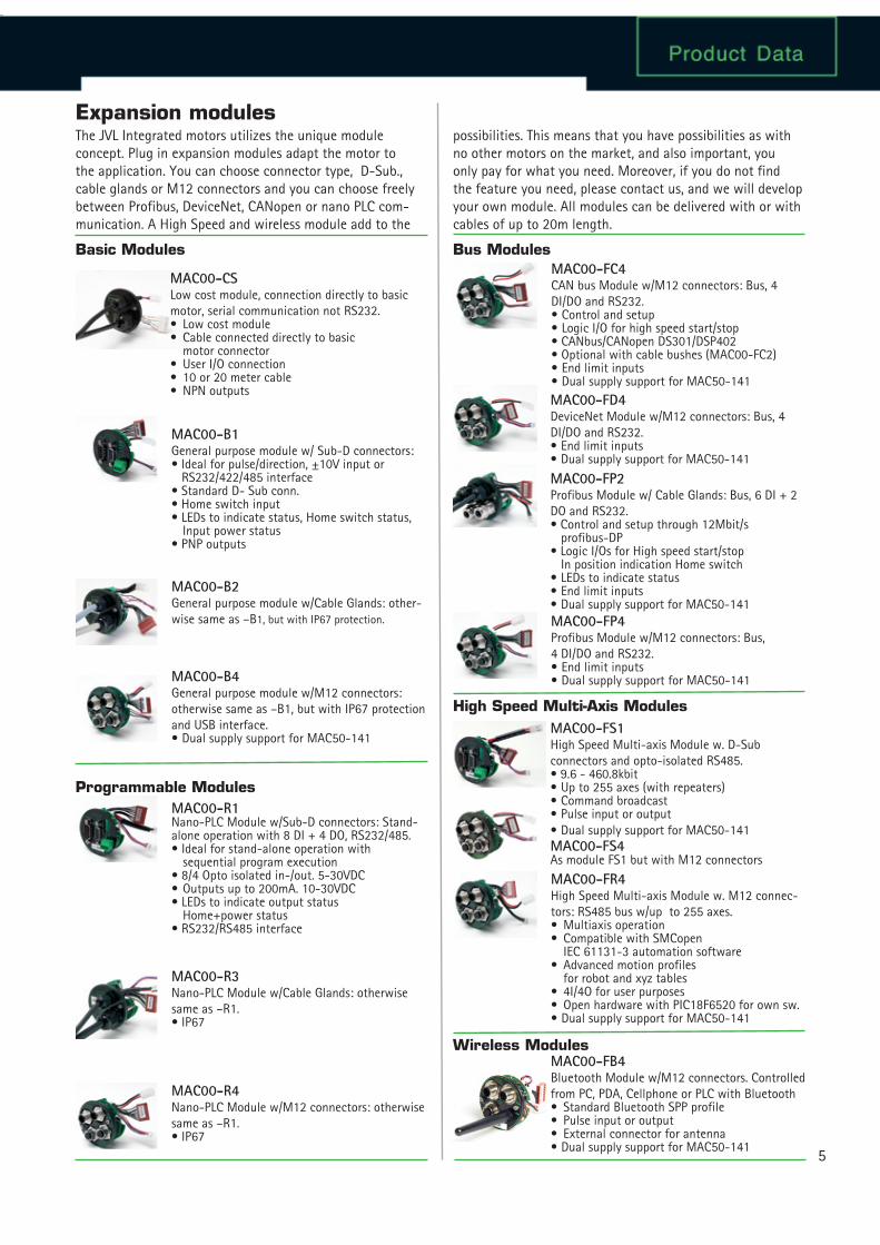
Expansion modules
MAC00-FR4High Speed Multi-axis Module w. M�2 connec-tors: RS485 bus w/up to 255 axes.• Multiaxis operation• Compatible with SMCopen IEC 6��3�-3 automation software• Advanced motion profiles for robot and xyz tables• 4I/4O for user purposes• Open hardware with PIC�8F6520 for own sw.• Dual supply support for MAC50-�4�
MAC00-CSLow cost module, connection directly to basic motor, serial communication not RS232.• Low cost module• Cable connected directly to basic motor connector• User I/O connection• �0 or 20 meter cable• NPN outputs
MAC00-B1General purpose module w/ Sub-D connectors: • Ideal for pulse/direction, ±�0V input or RS232/422/485 interface• Standard D- Sub conn.• Home switch input• LEDs to indicate status, Home switch status, Input power status• PNP outputs
MAC00-B2General purpose module w/Cable Glands: other-wise same as –B�, but with IP67 protection.
MAC00-B4General purpose module w/M�2 connectors: otherwise same as –B�, but with IP67 protection and USB interface.• Dual supply support for MAC50-�4�
MAC00-R1Nano-PLC Module w/Sub-D connectors: Stand-alone operation with 8 DI + 4 DO, RS232/485.• Ideal for stand-alone operation with sequential program execution• 8/4 Opto isolated in-/out. 5-30VDC• Outputs up to 200mA. �0-30VDC• LEDs to indicate output status Home+power status• RS232/RS485 interface
MAC00-R3Nano-PLC Module w/Cable Glands: otherwise same as –R�.• IP67
MAC00-R4Nano-PLC Module w/M�2 connectors: otherwise same as –R�.• IP67
MAC00-FS1High Speed Multi-axis Module w. D-Sub connectors and opto-isolated RS485.• 9.6 - 460.8kbit• Up to 255 axes (with repeaters)• Command broadcast• Pulse input or output• Dual supply support for MAC50-�4�MAC00-FS4As module FS� but with M�2 connectors
MAC00-FP2Profibus Module w/ Cable Glands: Bus, 6 DI + 2 DO and RS232.• Control and setup through �2Mbit/s profibus-DP• Logic I/Os for High speed start/stop In position indication Home switch• LEDs to indicate status• End limit inputs• Dual supply support for MAC50-�4�MAC00-FP4Profibus Module w/M�2 connectors: Bus, 4 DI/DO and RS232.• End limit inputs• Dual supply support for MAC50-�4�
MAC00-FC4CAN bus Module w/M�2 connectors: Bus, 4 DI/DO and RS232.• Control and setup• Logic I/O for high speed start/stop• CANbus/CANopen DS30�/DSP402• Optional with cable bushes (MAC00-FC2)• End limit inputs• Dual supply support for MAC50-�4�MAC00-FD4DeviceNet Module w/M�2 connectors: Bus, 4 DI/DO and RS232.• End limit inputs• Dual supply support for MAC50-�4�
MAC00-FB4Bluetooth Module w/M�2 connectors. Controlled from PC, PDA, Cellphone or PLC with Bluetooth• Standard Bluetooth SPP profile• Pulse input or output• External connector for antenna• Dual supply support for MAC50-�4�
Basic Modules Bus Modules
Programmable Modules
High Speed Multi-Axis Modules
Wireless Modules
The JVL Integrated motors utilizes the unique module concept. Plug in expansion modules adapt the motor to the application. You can choose connector type, D-Sub., cable glands or M�2 connectors and you can choose freely between Profibus, DeviceNet, CANopen or nano PLC com-munication. A High Speed and wireless module add to the
possibilities. This means that you have possibilities as with no other motors on the market, and also important, you only pay for what you need. Moreover, if you do not find the feature you need, please contact us, and we will develop your own module. All modules can be delivered with or with cables of up to 20m length.
6
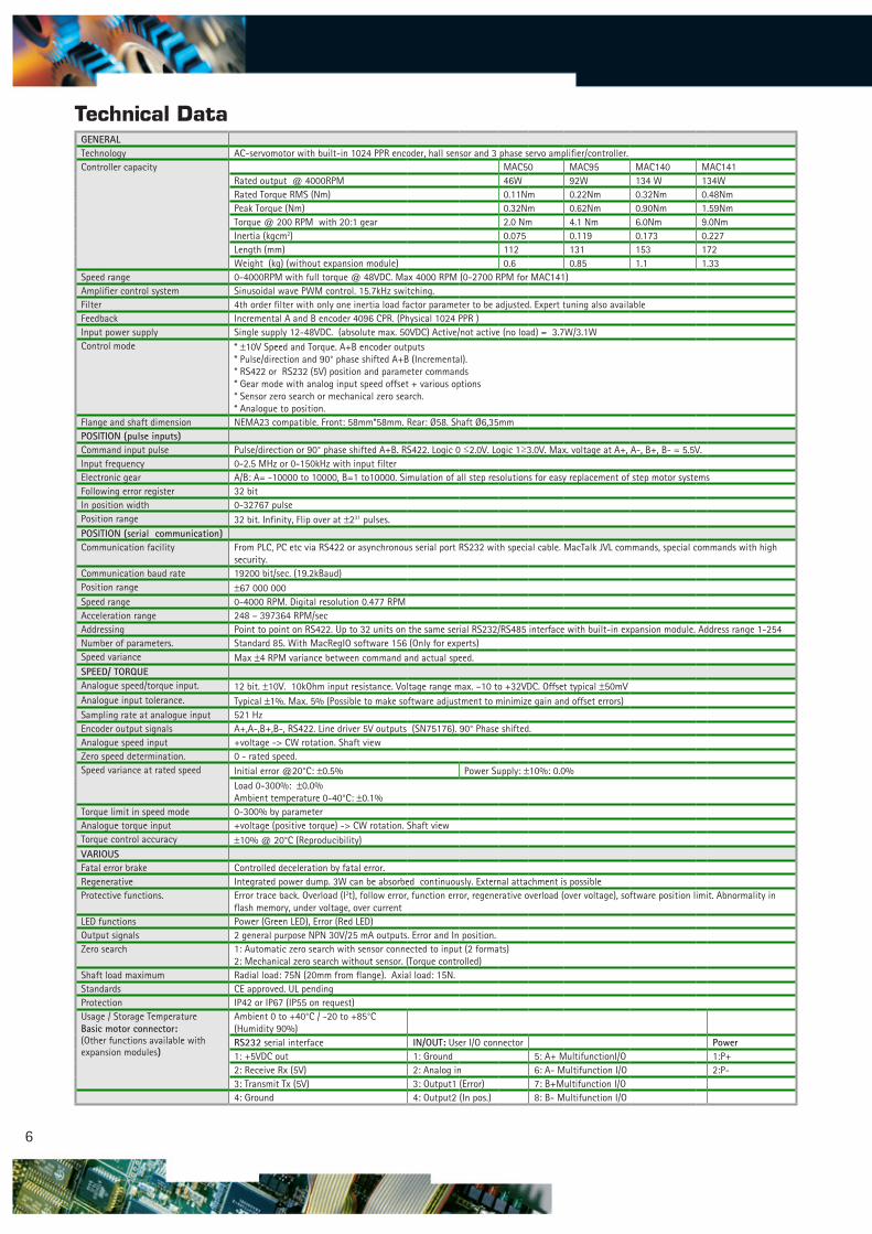
Technical DataGENERAL Technology AC-servomotor with built-in �024 PPR encoder, hall sensor and 3 phase servo amplifier/controller. Controller capacity MAC50 MAC95 MAC�40 MAC�4�
Rated output @ 4000RPM 46W 92W �34 W �34WRated Torque RMS (Nm) 0.��Nm 0.22Nm 0.32Nm 0.48NmPeak Torque (Nm) 0.32Nm 0.62Nm 0.90Nm �.59NmTorque @ 200 RPM with 20:� gear 2.0 Nm 4.� Nm 6.0Nm 9.0NmInertia (kgcm2) 0.075 0.��9 0.�73 0.227Length (mm) ��2 �3� �53 �72Weight (kg) (without expansion module) 0.6 0.85 �.� �.33
Speed range 0-4000RPM with full torque @ 48VDC. Max 4000 RPM (0-2700 RPM for MAC�4�)Amplifier control system Sinusoidal wave PWM control. �5.7kHz switching.Filter 4th order filter with only one inertia load factor parameter to be adjusted. Expert tuning also availableFeedback Incremental A and B encoder 4096 CPR. (Physical �024 PPR ) Input power supply Single supply �2-48VDC. (absolute max. 50VDC) Active/not active (no load) = 3.7W/3.�W Control mode * ±�0V Speed and Torque. A+B encoder outputs
* Pulse/direction and 90° phase shifted A+B (Incremental).* RS422 or RS232 (5V) position and parameter commands* Gear mode with analog input speed offset + various options* Sensor zero search or mechanical zero search.* Analogue to position.
Flange and shaft dimension NEMA23 compatible. Front: 58mm*58mm. Rear: Ø58. Shaft Ø6,35mmPOSITION (pulse inputs) Command input pulse Pulse/direction or 90° phase shifted A+B. RS422. Logic 0 ≤2.0V. Logic �≥3.0V. Max. voltage at A+, A-, B+, B- = 5.5V.Input frequency 0-2.5 MHz or 0-�50kHz with input filterElectronic gear A/B: A= -�0000 to �0000, B=� to�0000. Simulation of all step resolutions for easy replacement of step motor systemsFollowing error register 32 bit In position width 0-32767 pulsePosition range 32 bit. Infinity, Flip over at ±23� pulses.POSITION (serial communication) Communication facility From PLC, PC etc via RS422 or asynchronous serial port RS232 with special cable. MacTalk JVL commands, special commands with high
security. Communication baud rate �9200 bit/sec. (�9.2kBaud)Position range ±67 000 000Speed range 0-4000 RPM. Digital resolution 0.477 RPMAcceleration range 248 – 397364 RPM/sec Addressing Point to point on RS422. Up to 32 units on the same serial RS232/RS485 interface with built-in expansion module. Address range �-254 Number of parameters. Standard 85. With MacRegIO software �56 (Only for experts) Speed variance Max ±4 RPM variance between command and actual speed. SPEED/ TORQUE Analogue speed/torque input. �2 bit. ±�0V. �0kOhm input resistance. Voltage range max. –�0 to +32VDC. Offset typical ±50mV Analogue input tolerance. Typical ±�%. Max. 5% (Possible to make software adjustment to minimize gain and offset errors) Sampling rate at analogue input 52� HzEncoder output signals A+,A-,B+,B-, RS422. Line driver 5V outputs (SN75�76). 90° Phase shifted.Analogue speed input +voltage -> CW rotation. Shaft viewZero speed determination. 0 - rated speed.Speed variance at rated speed Initial error @20°C: ±0.5% Power Supply: ±�0%: 0.0%
Load 0-300%: ±0.0% Ambient temperature 0-40°C: ±0.�%
Torque limit in speed mode 0-300% by parameterAnalogue torque input +voltage (positive torque) -> CW rotation. Shaft viewTorque control accuracy ±�0% @ 20°C (Reproducibility)VARIOUS Fatal error brake Controlled deceleration by fatal error.Regenerative Integrated power dump. 3W can be absorbed continuously. External attachment is possibleProtective functions. Error trace back. Overload (I2t), follow error, function error, regenerative overload (over voltage), software position limit. Abnormality in
flash memory, under voltage, over currentLED functions Power (Green LED), Error (Red LED) Output signals 2 general purpose NPN 30V/25 mA outputs. Error and In position. Zero search �: Automatic zero search with sensor connected to input (2 formats)
2: Mechanical zero search without sensor. (Torque controlled)Shaft load maximum Radial load: 75N (20mm from flange). Axial load: �5N.Standards CE approved. UL pending Protection IP42 or IP67 (IP55 on request)Usage / Storage TemperatureBasic motor connector:(Other functions available with expansion modules)
Ambient 0 to +40°C / -20 to +85°C (Humidity 90%)RS232 serial interface IN/OUT: User I/O connector Power�: +5VDC out �: Ground 5: A+ MultifunctionI/O �:P+2: Receive Rx (5V) 2: Analog in 6: A- Multifunction I/O 2:P-3: Transmit Tx (5V) 3: Output� (Error) 7: B+Multifunction I/O
4: Ground 4: Output2 (In pos.) 8: B- Multifunction I/O
7
MAC motor selection chart
Planetary and cycloidal gearheads
• Sealed Ball Bearings• High Reliability, High Efficiency Design• NEMA Mounting Standards• High Shaft Loading Capacity
• Low Backlash Design• Strong, Caged Roller Bearings• Precision Input Pinion with Balanced Clamp Collar
L�: Gear length incl. flange, D2: Gear housing diameter, D2:Output shaft diameter
HTRG type gears:
HSPG type gears:
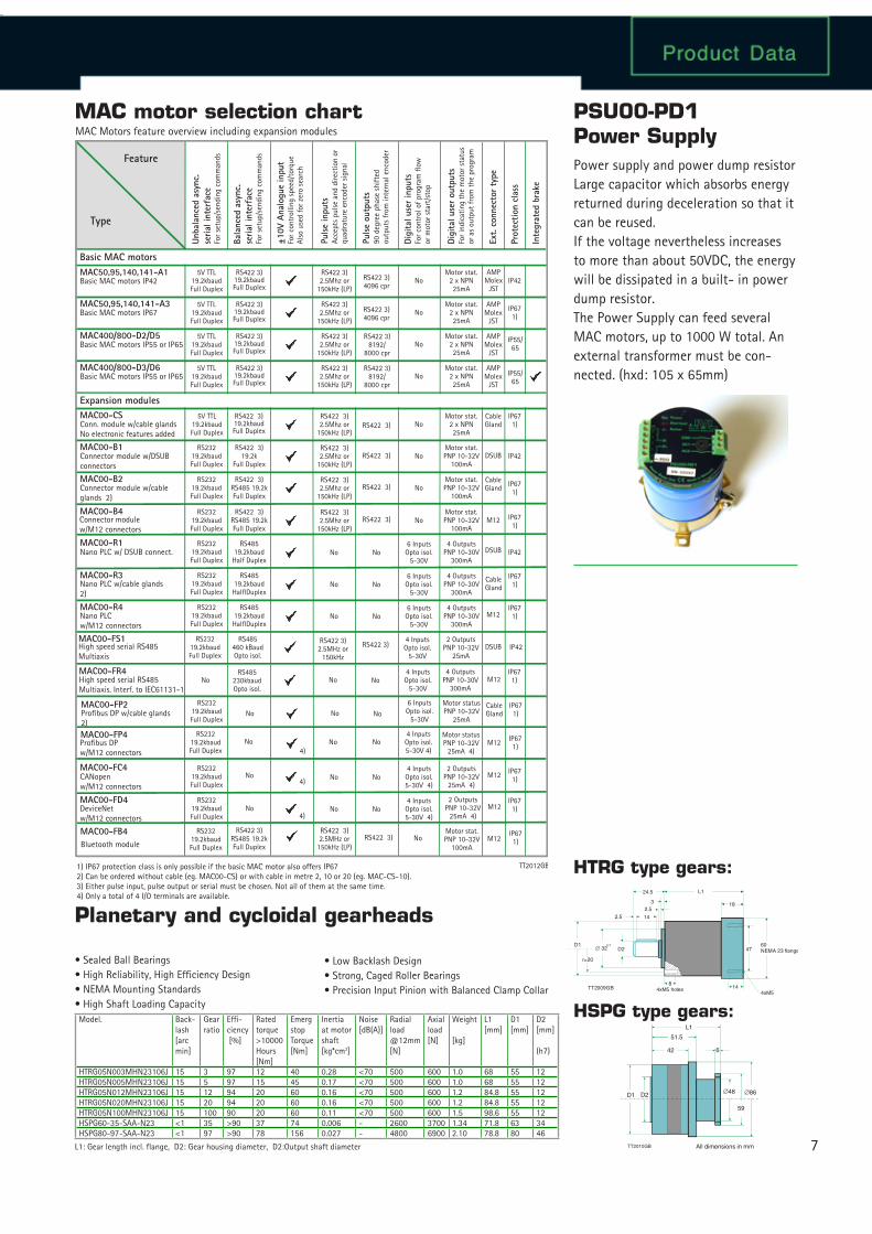
Power supply and power dump resistorLarge capacitor which absorbs energy returned during deceleration so that it can be reused.If the voltage nevertheless increases to more than about 50VDC, the energy will be dissipated in a built- in power dump resistor.The Power Supply can feed several MAC motors, up to �000 W total. An external transformer must be con-nected. (hxd: �05 x 65mm)
PSU00-PD1Power Supply
Model. Back-lash [arc min]
Gear ratio
Effi-ciency [%]
Rated torque>�0000 Hours [Nm]
Emerg stop Torque [Nm]
Inertia at motor shaft [kg*cm2]
Noise[dB(A)]
Radial load @�2mm[N]
Axial load[N]
Weight
[kg]
L� [mm]
D� [mm]
D2[mm]
(h7)
HTRG05N003MHN23�06J �5 3 97 �2 40 0.28 <70 500 600 �.0 68 55 �2HTRG05N005MHN23�06J �5 5 97 �5 45 0.�7 <70 500 600 �.0 68 55 �2HTRG05N0�2MHN23�06J �5 �2 94 20 60 0.�6 <70 500 600 �.2 84.8 55 �2HTRG05N020MHN23�06J �5 20 94 20 60 0.�6 <70 500 600 �.2 84.8 55 �2HTRG05N�00MHN23�06J �5 �00 90 20 60 0.�� <70 500 600 �.5 98.6 55 �2HSPG60-35-SAA-N23 <� 35 >90 37 74 0.006 - 2600 3700 �.34 7�.8 63 34HSPG80-97-SAA-N23 <� 97 >90 78 �56 0.027 - 4800 6900 2.�0 78.8 80 46
MAC50,95,140,141-A1
Unba
lanc
ed a
sync
.se
rial i
nter
face
For s
etup
/sen
ding
com
man
ds
Bala
nced
asy
nc.
seria
l int
erfa
ceFo
r set
up/s
endi
ng c
omm
ands
±10V
Ana
logu
e in
put
For c
ontr
ollin
g sp
eed/
torq
ueAl
so u
sed
for z
ero
sear
ch
Puls
e in
puts
Acce
pts
puls
e an
d di
rect
ion
orqu
adra
ture
enc
oder
sig
nal
Puls
e ou
tput
s90
deg
ree
phas
e sh
ifted
outp
uts
from
inte
rnal
enc
oder
Digi
tal u
ser
inpu
tsFo
r con
trol
of p
rogr
am fl
owor
mot
or s
tart
/sto
p
Digi
tal u
ser
outp
uts
For i
ndic
atin
g th
e m
otor
sta
tus
or a
s ou
tput
from
the
pro
gram
Ext.
conn
ecto
r ty
pe
Prot
ectio
n cl
ass
Inte
grat
ed b
rake
MAC50,95,140,141-A3
MAC400/800-D2/D5
MAC400/800-D3/D6
MAC00-CS
MAC00-B1
MAC00-B2
MAC00-B4
MAC00-R1
MAC00-FC4
MAC00-R3
MAC00-FD4
MAC00-FB4
MAC00-R4
MAC00-FS1
MAC00-FP2
MAC00-FP4
MAC00-FR4
Feature
Type
Basic MAC motors IP42
Basic MAC motors IP67
Basic MAC motors IP55 or IP65
Basic MAC motors IP55 or IP65
Conn. module w/cable glandsNo electronic features added
Connector module w/DSUBconnectors
Connector module w/cableglands 2)
Nano PLC w/ DSUB connect.
CANopenw/M�2 connectors
Nano PLC w/cable glands2)
Bluetooth module
Nano PLC w/M�2 connectors
Profibus DP w/cable glands2)
Profibus DP w/M�2 connectors
High speed serial RS485Multiaxis. Interf. to IEC6��3�-�
High speed serial RS485Multiaxis
MAC Motors feature overview including expansion modules
5V TTL�9.2kbaudFull Duplex
5V TTL�9.2kbaudFull Duplex
5V TTL�9.2kbaudFull Duplex
5V TTL�9.2kbaudFull Duplex
5V TTL�9.2kbaudFull Duplex
RS232�9.2kbaudFull Duplex
RS232�9.2kbaudFull Duplex
RS232�9.2kbaudFull Duplex
RS232�9.2kbaudFull Duplex
RS232�9.2kbaudFull Duplex
RS232�9.2kbaudFull Duplex
RS232�9.2kbaudFull Duplex
RS232�9.2kbaudFull Duplex
RS232�9.2kbaudFull Duplex
RS232�9.2kbaudFull Duplex
RS232�9.2kbaudFull Duplex
No
RS422 �9.2kbaudFull Duplex
3) RS422 2.5Mhz or
�50kHz (LP)
3)RS422 4096 cpr
3)
RS422 4096 cpr
3)
RS422 8�92/
8000 cpr
3)
RS422 8�92/
8000 cpr
3)
RS422 3)
RS422 3)
RS422 3)
RS422 3)
RS422 3)
No
No
No
No
No
No
No
No
No
No
No
No
No
No
No
RS422 3)2.5MHz or
�50kHz
TT20�2GB
No
No4)
4)
4)
No
No
No
No
No
RS422 3)
No
No
No
6 InputsOpto isol.
5-30V
4 InputsOpto isol.5-30V 4)
6 InputsOpto isol.
5-30V
4 InputsOpto isol.5-30V 4)
6 InputsOpto isol.
5-30V
4 InputsOpto isol.5-30V 4)
6 InputsOpto isol.
5-30V
4 InputsOpto isol.
5-30V
4 InputsOpto isol.
5-30V
Motor stat.2 x NPN25mA
Motor stat.2 x NPN25mA
Motor stat.2 x NPN25mA
Motor stat.2 x NPN25mA
Motor stat.2 x NPN25mA
4 OutputsPNP �0-30V
300mA
2 OutputsPNP �0-32V
25mA 4)
2 OutputsPNP �0-32V
25mA 4)
4 OutputsPNP
300mA�0-30V
4 OutputsPNP
300mA�0-30V
2 OutputsPNP �0-32V
25mA
Motor statusPNP �0-32V
25mA
Motor statusPNP �0-32V
25mA 4)
4 OutputsPNP
300mA�0-30V
Motor stat.PNP �0-32V
�00mA
Motor stat.PNP �0-32V
�00mA
Motor stat.PNP �0-32V
�00mA
Motor stat.PNP �0-32V
�00mA
AMPMolex
JST
AMPMolex
JST
AMPMolex
JST
AMPMolex
JST
DSUB
CableGland
M�2
CableGland
CableGland
M�2
CableGland
M�2
M�2
M�2
M�2
M�2
DSUB
DSUB
IP42
IP42
IP67�)
IP67�)
IP42
IP67�)
IP55/65
IP55/65
IP67�)
IP67�)
IP67�)
IP67�)
IP67�)
IP67�)
IP67�)
IP67�)
IP67�)
IP42
RS422 2.5Mhz or
�50kHz (LP)
3)
RS422 2.5Mhz or
�50kHz (LP)
3)
RS422 2.5Mhz or
�50kHz (LP)
3)
RS422 3)2.5Mhz or
�50kHz (LP)
RS422 3)2.5Mhz or
�50kHz (LP)
RS422 3)2.5Mhz or
�50kHz (LP)
RS422 3)2.5Mhz or
�50kHz (LP)
RS422 �9.2kbaudFull Duplex
3)
RS422 �9.2kbaudFull Duplex
3)
RS422 �9.2kbaudFull Duplex
3)
RS422 3)�9.2kbaudFull Duplex
RS422 3) �9.2k
Full Duplex
RS422 3) RS485 �9.2kFull Duplex
RS422 3) RS485 �9.2kFull Duplex
RS485�9.2kbaudHalf Duplex
RS485�9.2kbaudHalflDuplex
RS485�9.2kbaudHalflDuplex
RS485460 kBaudOpto isol.
No
No
No
No
RS485230kbaudOpto isol.
Basic MAC motors
Expansion modules
�) IP67 protection class is only possible if the basic MAC motor also offers IP672) Can be ordered without cable (eg. MAC00-CS) or with cable in metre 2, �0 or 20 (eg. MAC-CS-�0).3) Either pulse input, pulse output or serial must be chosen. Not all of them at the same time.4) Only a total of 4 I/O terminals are available.
Connector module w/M�2 connectors
RS232�9.2kbaudFull Duplex
RS422 3)RS485 �9.2kFull Duplex
RS422 3)2.5MHz or
�50kHz (LP)
84xM5 holes
142.5
2.53
24.5 L1
18
4xM514
4760NEMA 23 flange
D1∅ 32
h7D2
TT2009GB
r=20
D1
TT2010GB
D2
59
∅48 ∅86
L1
51.5
42 6
All dimensions in mm
8
JVL Industri Elektronik A/S
Blokken 42
DK-3460 Birkerød, Denmark
Tel: +45 4582 4440
Fax: +45 4582 5550
E-mail: [email protected] www.jvl.dk
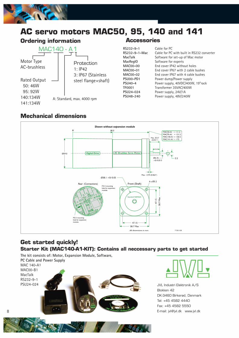
AC servo motors MAC50, 95, 140 and 141Ordering information Accessories
MAC140 - A 1
Motor TypeAC-brushless
Rated Output 50: 46W 95: 92W�40:�34W�4�:�34W
Protection�: IP423: IP67 (Stainless steel flange+shaft)
A: Standard, max. 4000 rpm
RS232-9-1 Cable for PCRS232-9-1-Mac Cable for PC with built in RS232 converterMacTalk Software for set-up of Mac motorMacRegIO Software for expertsMAC00-00 End cover IP42 without holesMAC00-01 End cover IP67 with 2 cable bushesMAC00-02 End cover IP67 with 4 cable bushesPSU00-PD1 Power dump/Power supply PSU40-4 Power supply, 40VDC/400W, �9”rackTF0001 Transformer 35VAC/400WPSU24-024 Power supply, 24V/�APSU48-240 Power supply, 48V/240W
Mechanical dimensions
Get started quickly!Starter Kit (MAC140-A1-KIT): Contains all neccessary parts to get startedThe kit consists of: Motor, Expansion Module, Software, PC Cable and Power SupplyMAC �40-A�MAC00-B�MacTalkRS232-9-�PSU24-024
80.00
Ø59.0
Ø38.1 +0/-0.05
47.1
5
58.7
Max
Ø6.35+0/-0.013
5.5
Max. 20.57(0.810 ’’)
15.0
47.15
58.7 Max
All dimensions in mm
Shown without expansion module
Rear (Connections) Front (Shaft)4 x Ø5.2
Max. 1.574 (0.062”)
Digital Drive AC-Brushless Servo Motor
Standard NEMA23
MAC50-A1 = 111.2MAC95-A1 = 131.5MAC140-A1 = 150.5MAC141-A1 = 172
TT2011GB
M2.5 mountinghole for expansionmodule.
M2.5 mountinghole for expansionmodule.