the intelligent management system: an overview · intelligent management system . speech...
TRANSCRIPT

The Intelligent Management System: An Overview
Mark S. Fox
The Robotics Institute Carnegie-melt on University
Pittsburgh, Pennsylvania 15213
. 7 becember 1982
Abstract: This paper describes the Intelligent Management System (IMS) project, which is part of the Factory of the Future project in the Robotics Institute of Carnegie-Mellon University. IMS is a long term project concerned with applying artificial intelligence techniques in aiding professionals and managers in their day to day tasks. This report discusses both the long term goals of IMS, and current research. It describes research in the modeling of organizations, constraint- based job-shop scheduling, organization simulation, user interfaces, and system architecture. Examples of working systems are provided.
Copyright @ 1982 Intelligent Systems Lab., CMU Robotics Inst.
This research was supported by the Robotics Institute, Carnegie-Mellon University, and, in part, by the Westinghouse Corporation. To appear in: "Processes and Tools For Decision Support", [H.Sol- Editor] Netherlands: North-Holland Company, 1982. Revised Version.
-. . .. . . - .. .


c
Intelligent Management System
Table of Contents 1. Introduction 2. Functional Goals 3. Architectural Goals 4. Organization Modelling
4.1. Introduction 4.2. Basic Modetling System 4.3. Model Accessibility and Extensibility 4.4. Flow-Shop Modelling 4.5. Job-Shop Modelling 4.6. Machine Modelling
5. Organization Analysis 5.1. Introduction 5.2. Simulation 5.3. Structure Analysis
6.1. Introduction 6.2. Job-Shop Scheduling 6.3. Factory Monitoring 6.4. Process Diagnosis
7.1. Introduction 7.2. Information Display 7.3. Natural Language Interface 7.4. Explanation 7.5. Discourse Modelling 7.6. Planning 7.7. Personalization
6. Organization Operation and Management
7. User Interfaces
8. Integrating Distributed Systems 9. Conclusion 10. Acknowledgments 11. References I. System Particulars
1 2 5 7 7
10 14
17 19 20 20 20 21 23 24 24 24 28 28 28 28 29 2!3 30 30 30 31 31 32 33 33 35
i


Intelligent Management System
List of Figures Figure 3- 1 : IMS System Architecture Figure 4- 1 : Machine Schema Figure 4-2: Machine Schema with values Figure 4-3: Machine Schema with facets Figure 4-4: Machine Schema with characters Figure 4-5: Continuous-Machine Schema Figure 4-6: PcOven Schema Figure 4-7: Activity Schema Figure 4-8: Flow-Shop Partial Model Figure 4-9: Monitoring the Factory Figure 4- 10: Monitoring the Inspection Area Figure 5- 1 : User Interface Display for Simulation Figure 6- 1 : Scheduling System
8 11
12
13 14
15 15 16
18 19 20 23 27
ii

Intelligent Management System
1. Introduction Classical research in the area of factory automation has been concerned more with production
processes than with management. Yet, it has been observed that in many small batch-size factories,
white collar labor accounts for a large fraction of total labor cost, and in some cases exceeds 50%.
And that small batch-size production accounts for 50%-75% of the dollar value of durable goods
produced in the United States. In metal-cutting, job-shop production environments, it has been found
that only 20% of the time an order is in a factory, is it actually mounted on a machine. And during only
5%-10% of its time on the machine, are value-adding operations being performed (Am. Mach., 1980).
There are (at least) two approaches to dealing with this problem. The first is to discover new methods
of producing products that do not suffer from these inefficiencies. The second approach is to
increase the effectiveness of professional and managerial personnel. The project described herein is
concerned with the latter.
In the summer of 1980 we began the design and construction of what we call an Intelligent
Management System (IMS). Research in IMS flows in two directions. The first is concerned with
creating theory and systems whose functionality will aid professional and managerial personnel in
their day 'to day decision making. These systems must be more effective in the tasks they perform.
They must integrate and communicate the knowledge and skill of the whole organization, making
them available for management decisions. More importantly, they must aid professionals and
managers in carrying out tasks. Management systems must become more intelligent.
The second direction of our research is concerned with reducing the cost of creating, maintaining,
and adding new functionality. It is not sufficient to increase the effectiveness of one part of an
organization, e.g., managerial, by increasing costs in another, namely programming and system
support. Yet much of the software constructed today, while providing increased functionality, also
requires increased programming support. Research and development must be concerned not only
with functionality but with adaptability.
The methodological focus of IMS is not the creation of an information system to support decision
making as typically found in decision support research (Alter, 1979), but to explore more ill-structured
problems (Simon, 1960) by means of heuristic problem-solving techniques. Ten years ago the
promise of artificial intelligence techniques was unclear, but advances in the last decade have
resulted in systems that display surprising capabilities and in some cases perform better than experts
in the field. Examples can be found in Computer Layout: R1 (McDermott, 1980); Medical Diagnosis:
Mycin (Shortliffe, 1976), Internist (Pople, 1977); Geological Analysis: Prospector (Duda et at., 1978);
1

Intelligent Management System .
Speech Understanding: Hearsay-ll. (Erman et al., 1980), Harpy (Lowerre, 1977). It is our goal to
explore the application of artificial intelligence to managerial and professional problems.
This paper describes both the goals of the IMS research, and the research performed to date in
organization modeling, operations control, management, and analysis, and in interfaces provided to
the user. AI knowledge representation techniques form the basis of our modeling system. They
provide both flexibility and richness in representation, resulting in a single model which can support a
variety .of functions. Constraint-directed. and rulebased problem-solving architectures are used to
perform organization control, management, and analysis. These architectures easily incorporate
constraints/heuristics in the performance of control and management tasks such as job-shop
scheduling and trend analysis. And natural language parsers and rule-based architectures are used
to construct flexible user-interfaces.
The next two sections of the paper describe both the functional and architectural
Following them are sections describing research in organization modeling, analysis,
and in user-interfaces and system architecture.
2. Functional Goals The broad functional goals of the Intelligent Management System Project include:
goals of IMS.
management,
1. Providing expert assistance in the accomplishment of professional and managerial tasks, and
2. Integrating and coordinating the management of the organization.
These goals were refined by analyzing professional and managerial needs. Over 30 managers from
three plants in the Westinghouse Corporation were asked to record the types of questions they
frequently faced during the performance of their jobs. Some of the questions were concerned with
the status of activities. But the majority were in the area of "decision support", where the decisions
spanned the areas of operations control to advance planning. The following is just a few of their
replies:
0 What is the effect of changes in engineering specifications: designs, materials, process specifications, etc?
I S
0 What is the proper inventory level at various levels, Le., raw, work in progress, finished parts, etc?
2

. Inte!ligent.Management System
0 What if the jig grinder goes down.with maintenance problems?
*Based on downtime, cost of maintenance and cost of replacement parts, how do I determine when to buy a new piece of production equipment?
0 Charlotte moves one (1) 6672 rotor two (2) months ahead of schedule and Lester moves two (2) 6622 rotors.back in schedule. .
1. How are all promised dates for next six months affected?
2. What manpower changes are needed by cost center to accomplish changes?
3. What material delivery changes need to be made?
0 How do I select the process to be used? What if the shop changes the plan and needs to perform a particular job on a different machine from the standard?
0 Not enough information concerning the current state of production.on the floor, orders in process, problems etc. is communicated quickly and succinctly to interested parties within the plant.
0 Changes to products or tools by the engineering division are not adequately .
communicated and coordjnated with changes taking place in the factory.
0 If I have a database containing lamp prices, sales volume, ics (internal product cost) transportation cost, overhead allotment, .. for all lamp types. What will the profit be if I change transportation, or change the source of manufacturing.
0 Predict machine failures and prescribe preventative maintenance by sound vibration, machine timing, shrjnkage trends, and end of normal part life.
0 Determine correlations between gas, fill, temperature, stack up, and shrinkage.
In order to solve these problems, the Intelligent Management System must:
0 Sense: Automatically acquire state data. Sense the location of objects, state of machines and status of activities both on the plant floor and in supervisory departments.
0 Model: Model the organization at many levels of abstraction. For example, machines, people, materials, orders, departments, need to be modeled in detail from both an attribute and a process view, including their interactions, authority, and communication.
...
3

Intelligent Management System
...
e Operate: Provide expert assistance in the accomplishment of complex professional tasks within the organization.
e Manage:
o Analyze and manipulate the model to schedule production and resource utilization, and answer short and long term state and planning questions. The system in this role is passive in that it responds to user initiated queries.
_ .
o Actively monitor the organization and inform responsible personnel when important events occur. For example, when a machine break down occurs, not only is the foreman informed, but also maintenance, and the salesman who must inform the client that the order will be delayed.
e Analyze-Optimize: Analyze how the structure and the processing of the organization should be changed to further optimize some criteria such as cost, throughput, and quality.
The &ove goals are concerned more with "what" functionalism is provided than "how" it is
provided. Included in the functional goals of IMS is the need for better user interfaces. The following , _ _ scenarios depict how the user interface should be integrated with the rest of the system.
"Tell me when ... ": The marketing manager is under heavy pressure to get a rather large order
out of the factory. He wants to be informed the minute it is shipped. He turns to his terminal and
types the message: "Inform me when order X is shipped." His User Interface Process (UIP) translates
the request into a rule "IF order X is Shipped THEN send message to manager Y", and sends it to the
shipping Task Management Process (TMP). The TMP monitors the system to determine when the rule
condition occurs. When the order is shipped, the TMP interprets the rule, resulting in the shipping
message being sent.
"You've got problems ..." :The milling machine breaks a tool while cutting a high priority order.
The machine and order are damaged. The machine's sensors transmit the information to its Machine
Supervisory Process (MSP). The MSP analyzes the problem, and shuts down the machine. It then
informs the floor supervisor and the scheduler TMP of the breakdown; the scheduling TMP re-routes
orders. A message is also sent to the maintenance TMP which allocates a maintenance person to fix
the machine. Lastly, the MSP checks the importance of the order, and informs marketing and other
personnel of the problem, if it affects their tasks.
4
Intelligent Management System
"What i f ..." ; The manager in charge of production is considering the problem of a continually
large back-log oforders. Should another machine be bought, or should the orders be subcontracted?
He/she turns to hidher terminal and types in: "What are the effects on orders over the next six
months i f we buy another machine X?" The system then enters into a dialogue with the manager
determining other information required to analyze the question. The UIP then scans the system wide
functions that may help answer the problem. It finds a simulation module that can analyze structural
changes in an organization. It gathers the initialization data and alters the factory model. It then runs
the simulation, analyzes the output and provides the manager with the answer, and further
explanations.
Obviously, creating a system that satisfies these goals will require many years of research and
development. Never the less, it is important to understand the long-term goals so that short-term
research is properly directed.
3. Architectural Goals A necessary characteristic of any management system is that it provide the requisite functionality.
But in most cases this is not sufficient. Unless the organization and its environment is static, system
functions will quickly become inappropriate and fall into disuse. When the software maintenance is
quoted to be 90% of software costs, this is due more to software adaptation than to software errors.
We believe it is just as, i f not more important, to attend to architectural goals as to functional goals.
Then if the provided functionality is not applicable, the architecture will reduce the complexity of
alteration;
In IMS, three levels of architecture are distinguished:
Hardware: The hardware level encompasses both the number and types of processors, and their networking.
Software: The software level covers the process architecture, process description languages, protocols for communication, module functionality, and databases.
User Interface: The user interface level covers the means by which the user can communicate with the system functions.
As an organizations changes, the hardware must also change, reliably providing services at the
point of need. While timesharing systems are accessible, Le., can provide services at the point of
need, their reliability and adaptability are limited. (Some) Distributed systems connected by general
5
. Intelligent. Management System
communication networks can expand on demand, provide service at the point of need, and also shift
processing loads when nodes fail.
Software must be general in the sense that modules, i.e, programs, can be used in more than one
situation or application. For example, a factory modeling system can support more than one
application such as simulation and scheduling. If the software does not provide the functionality it
should not be difficult to extend. It should be extendible in the sense of program functionality, and in
the sense that new modules and processes can be added to the system without requiring alterations
to existing software. Currently, software systems are tightly coupled, requiring extensive re-
programming whenever changes are required.
Lastly, the user interface must have the following characteristics:
Accessibility: Interfaces to computer systems are usually idiosyncratic and difficult to learn and use. Also, systems that change require that their users be continually re- educated. Our goal for IMS is to enable all personnel to meaningfully communicate with it. The interface will gracefully.interact with the user and prQVide guidance and help in deciding what the user needs.
Accountability: A major obstacle to computer acceptance is that users are unable to question how and why output was generated. Our goal is to construct an explanation system which will allow IMS to explain its actions at various levels of detail.
'
Adaptability: As the user's needs change, the interface must be able to alter its processing and responses to fit the changes.
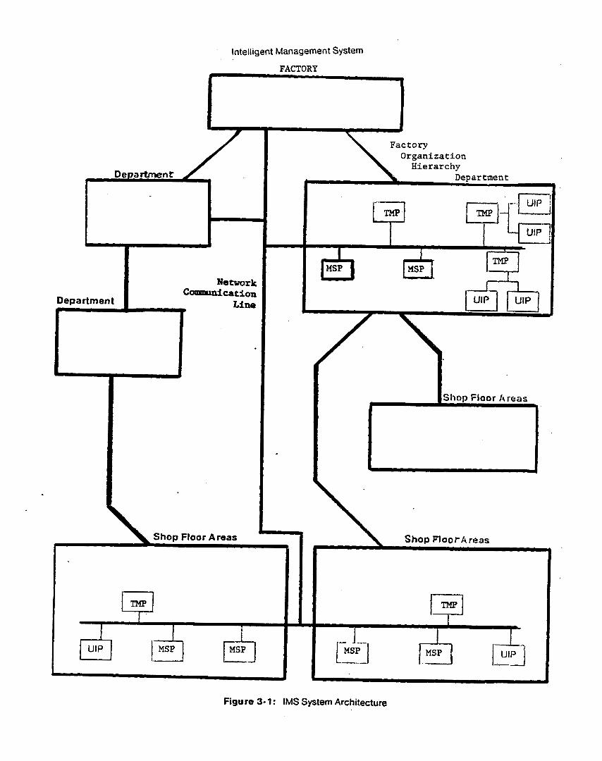
The results of our research have been targeted to run in a distributed, multi-processor and process
environment (figure 3-1). Employee's will have a User Interface Process (UP) that will act as an intelligent "aide". A UIP is composed of a personal computer, graphics display, keyboard,
microphone, and network interface (e.g., a SPICE machine (CMU-CSD, 1979)). The UIP will have
either voice or typed natural language input. It will act as an "aide" in the sense that it will interpret
and implement user requests and queries. All UlPs will be inter-connected via a communication
network allowing them to cooperatively interact to solve problems and communicate information. The
UIP will also carry out many of the employees well-structured tasks automatically. Each machine will
have a Machine Supervisory Process (MSP) which monitors and controls it. It is also connected to
the network, and can reply to queries and commands initiated by other MSPs OL UlPs on the network.
Lastly, there are Task Management Processes (TMP). A TMP provides the focus for task
management. It does more of the mundane task monitoring and control, freeing managers to do the
Intelligent Management System
more complex decision making tasks.
4. Organization Modelling
4.1. Introduction
The purpose of organization modeling is to provide the information base upon which intelligent
processes rely. What the content of a model should be, and how it is represented is dependent upon
the processes that use it. It is safe to say that an "Intelligent Management System" will require at
least as much information as humans. The richness and variety of this information cannot be found in
the databases of current management information systems. Nor is the form of the organization model
related to current notions of database structures.
For example, a simulation system requires knowledge of existing processes including process
times, resource requirements, and its structural (routing) relation to other processes. It must also
know when routings for products are static, or are determined by a decision process such as a
scheduler. In the latter case, it must know when and where to integrate the scheduler into the
simulation. If IMS is to generate the sequence of events tc produce a new product, it must have
knowledge of processes (e.g., machines) which includes the type of processing it can do, its
operating constraints, the resources it consumes, and its operating tolerances. If data is to be
changed in an interactive, possibly natural language mode, IMS must have knowledge of generic
processes such as machines, tasks, and departments if it is to understand the interaction. It must
also know what information is important and how it relates to other information in order to detect
missing information and inconsistencies. Hence, the organizational model must be able to represent
object and process descriptions (structural and behavioral), and functional, communication and
authority interactions and dependencies. It must represent individual machines, tools, materials, and
people, and also more abstract concepts such as departments, tasks, and goals.
Consider a process model of a fluorescent lamp production machine group. The purpose of a
process model is to represent each physical process and the causal relations which link it with other
processes. For example, the Lehr' process comprises of hundreds of subprocesses concerned with
bulb grasping, positioning, heating, cooling, etc Each is sequentially related with others in time. The
performance of each is related'to the performance of previous subprocesses. Each subprocess is
described in terms of how it physically performs, its three dimensional movement, what and how it
'Baking lacquer out of lamp phosphor.
7
Intelligent Management System
Factory Organization Hierarchy
Shop Floor k reas I
Shop Flootk reas
Figure 3- 1 : IMS System Architecture

. Intelligent Management System
may grasp and heat an object, what object it expects, operating constraints, etc. The scope of the
description is limited only by the uses to be made of it, and the information available.
One use of such a model is for machine diagnosis. Engineers spend a great deal of time watching
a malfunctioning machine to determine what has gone wrong and what variables to alter to improve
performance. One of the major stumbling blocks in the systematic analysis of such systems is the
unavailability of process instrumentation for data collection. Yet the availability of the data solves only
half of the problem. The other is the automatic analysis of data to find relations between system
parameters and productivity. Statistical correlations are only a small part of the analysis. Statistics
alone can only suggest relations. Understanding whether the relation is valid requires a thorough
knowledge of the process itself and all its interactions. This cannot be performed without a
sufficiently rich model of the process describing physical, functional, and time relations.
Another use of a model is to provide process cost analysis. Given a model, questions about the
resource consumption and production of each process and subprocess can be answered. The
individual process descriptions can be integrated across the group. to provide summary cost
information. But more importantly, because the model represents not only the process but the effects
and relations among processes, questions related to process alterations can also be analyzed. For
example, what will the effect on cost be of changing a Lehr process to use microwave heating. And
from a diagnosis point of view, we would want the system to determine whether the change would
have any significant effect on shrinkage*. For example, the temperature of fhe glass may be lower
after microwaving, hence the following process, end sealing, may not have glass at a high enough
temperature.
In summary, the modeling system should provide:
1. A rich source of information.
2. A context within which all IMS modules can interact.
But if it is to be used in a changing environment and by non-programmers, it should also provide the
following features:
Accessibility: the model user should be able to easily peruse the model to determine its attributes and structure.
*loss through defects.
9
Intelligent Management System
Extensibility: the model should be alterable by its users.
Consistency. when a model is created or extended, the modeling system should be able to determine when the model contains inconsistent information.
4.2. Basic Modelling System
The above discussion presents a case for a modeling system that supports a variety of functionality
such as simulation, cost analysis, and process diagnosis, and a flexible user interface. Therein lies
the question: does such a modeling system exist'? Traditional, computer-based modeling systems fall
into four categories:
.
1. Mathematical.
2. Discrete event, facility based.
3. Continuous.
4. Arbitrary program.
In looking at these modeling systems, we found that:
0 They are too problem specific, hence inflexible.
0 The modeling techniques are difficult to learn by managers and engineers who are the prime users.
0 Alteration may require substantial change to the model and related systems.
0 Once constructed, the models are difficult to understand, peruse and verify.
The Intelligent Management System has at its core, a model of the organization. This model is
shared by all subsystems to achieve their tasks. The modeling system provides the following features:
0 The model is composed of declarative objects and relations which match the users conceptual model of the organization. . .
0 The modeling system provides a library of objects and relations which the user may use, alter, and/or extend in their application.
0 The model incorporates a variety of representational techniques allowing a wide variety
10

Intelligent Management System
of organizations to be modeled (continuous and discrete). And it is extensible, allowing the incorporation of new modeling techniques.
0 The user interactivelydefines, alters, and peruses the model.
0 The model can be easily instrumented. For example, the model can be diagrammatically displayed on a color graphics monitor at different levels of abstraction. The complete organization, or parts thereof, can be viewed with summaries (e.g., queue lengths, state).
*The modeling system,is simple to learn to use because the modeling tools match the concepts people use to think about problems.
The modeling system is based on the knowledge representation system SRL: Schema
Representation Language (Fox, 1979a; 1982). SRL has its basis in schemata (Bartlett, 1932), which
have come to been known as frames (Minsky, 1975), Concepts (Lenat, 1976), and Units (Bobrow 8
Winograd, 1978).
The basic unit for representing objects, processes, ideas, etc. is the Schema. Physically, a
schema is composed of a schema name (printed in the bold font) and a set of slots (printed in small
caps). A schema is always enclosed by double braces with the schema name appearing at the top.
{{ Machine
CAPACITY:
QUEUE:
OPERATOR:
CONTENTS:
LOAD:
UNLOAD:
11 Figure 4- 1 : Machine Schema
The Machine schema (figure 4-1) contains six slots, some which define physical limitations of the
machine, i.e., CAPACITY, some which define its current Status, i.e., OPERATOR, and some which define
11

Intelligent. Management System
{{ Machine
CAPACITY: 3 OPERATOR: jOe .
CONTENTS: lot-= LOAD:
UNLOAD:
11 Figure 4-2: Machine Schema with values
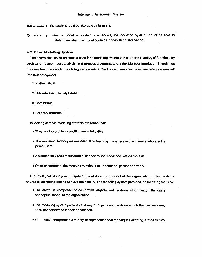
event behavior, i.e., LOAD. Slots can have simple values (figure 4-2). Schemata can be more
complex. Each slot has a set of associated facets (printed in italics) (figure 43). The Restriction facet
restricts the type of values that may fill the slot. The Default facet defines the value of the slot i f it is
not present. And each filler of a facet may have one or more pieces of meta-information termed
characters (printed underlined) (figure 44). The Fillel character defines the value of the facet.
Creator defines who created the filler. and Creation-Date defines when the filler was created. An
important aspect of SRL is that schemata may form networks. Each slot in a schema may act as a
relation tying the schema to others. The schema may inherit slots and their fillers along these
relations. Consider the schema for a Continuous-machine. Figure 4-5 defines a
CONTINUOUS-MACHINE which works much like a pizza oven, it can be continuously filled up to
capacity. A Continuous-Machine IS-A Machine. The IS-A relation between the two schemata
allows Continuous-Machine to inherit attributes (slot names) and their values from the Machine
schema. The LOAD slot defines the behavior of the machine when a load event occurs. The loading
rule tests whether the machine has capacity, if so the object is placed in the machine, otherwise it is
queued.
SRL provides the model builder with the ability to define new schemata and slots, and to define the
inheritance semantics of slots which act as relations. This includes defining what information, i.e.,
slots and their values,'is inherited, not inherited, and altered when inherited.
The Machine and Continuous-Machine schemata are generic schemata that form part of the
basic modeling system. The system contains a variety of basic schemata which the model builder can
12

Intelligent Management System
{{ Machine
CAPACITY:
Value: 3
Va/ui:'joe
Restriction: (TYPE is-a product)
Restriction: (SET (TYPE is-a rule)) Default: load-rule
Restriction: (SET (TYPE is-a rule)) Default: unload-rule
OPERATOR:
CONTENTS:
LOAD:
UNLOAD:
Figure 4-3: Machine Schema with facets
use to model an individual organization. An organization model is constructed by instantiating the
basic schemata with appropriate attribute values, e.g., capacity, and possibly, new behavioral rules.
Schemata are structured (linked) through a user extendible set of relations: IS-A, INSTANCE, PART-OF,
etc. For example, a circuit board baking oven (figure 4-6) can be instanced as an INSTANCE of a
Continuous-Machine. It has a CAPACITY of 10, and inherits its loading rule from
Continuous-Machine. It is also part of a Work-Area in the plant called the Baking-Shop. The
PART-OF relation allows the inheritance of locational information.
Another type of schema used in project modeling and management is the activity schema (figure
4-7). An activity is defined as having four slots (attributes). The PRE-CONDITION defines what must
be true before the activity is to take place, e.g., materials available, previous activities finished. The
SUSTAINED-CONDITION defines what must be true throughout the activity, e.g., water-level in machine
is to be maintained above a certain level. The POST-CONDITION defines what must be true when the
activity is finished, e.g., the temperature of the part is above 100. Finally, the SUB-ACTIVITY points to
the sub-activities which comprise the activity. Activity schemata can be constructed into a network to
define both parallel and sequential precedence, and hierarchical to describe activities to many levels
13
Intelligent Management System
{{ Machine
CAPACITY:
Value: m: 3 Creator: shop-supervisor Creation - Date: 22-OCT- 79
OPERATOR:
Value: m: joe
CONTENTS:
Restriction: m: (TYPE is-a product)
LOAD:
Restriction:
Default:
m: (SET (WPE is-a rule))
- Filler: load-rule UNLOAD:
Restriction:
Defau/t: - Fim: (SET (TYPE is-a rule))
m: unload-rule
11 Figure 4-4: Machine Schema with characters
of detail (decomposition).
4.3. Model Accessibility and Extensibility
Current management information systems require the use of programmers when changes are made
to the organization model. While such an approach is fine for domains where the model changes
seldomly, the dynamics of a factory organization require continual updating of the model; both
parametric and structural changes are constantly occurring. In lieu of employing a brigade of
programmers to implement changes, the alternative is to construct a model acquisition system that
14

Intelligent. Management System
~~
{{ Continuous-Machine { IS-A Machine
USED- C AP AClTY : LOAD: { INSTANCE # rule
IF: (< USED-CAPACITY CAPACITY)
THEN: (fill USED-CAPACITY ( + 1 USED-CAPACITY))
ELSE: (add object QUEUE) } (add object CONTENTS)
1 11
Figure 4-5: Continuous-Machine Schema
{{ PcOven
{ INSTANCE Continuous-Machine CAPACITY: 10 }
{ PART-OF Baking-Shop }
Figure 4-6: PcOven Schema
allows the person initiating the change, to directly inform IMS of the modifications.
The IMS modeling system currently provides the following functionality:
0 Accessibility: The user may interactively view each schema in the model using a variety of schema printing functions. Relational hierarchies can also be displayed. Color graphic display of the model is supported at various levels of abstraction.

Intelligent Management System
{{ activity PRE-CONDITION:
SUSTAINED-CONDITION:
POST-CONDITION:
SUB- ACTIVITY: }}
Figure 4-7: Activity Schema
0 Extensibility: An interactive schema editor allows the user to create and alter schemata in the model.
0 Consistency: A model consistency language and checker has been developed (Reddy 8 Fox, 1982). The consistency checker uses the consistency specifications to check a model and reports inconsistencies to the user.
%?;
Though the above mechanisms provide a reasonable user interface to the modeling system, our
ultimate goal is to allow managers to alter the model directly. By means of a natural language
interface, the manager should be able to describe to IMS changes that have occurred in his area of
responsibility. To achieve this, the modeling system interface must:
1. Determine what part of the factory model is affected by the new information.
2. Check to see if the new information is consistent with what it already knows about the factory.
3. Determine the effect of the change on other parts of the model, and make the appropriate changes.
4. Query the manager when inconsistencies appear in the reconciliation of the new information with the existing model.
A natural language understanding and discourse modeling system to support model acquisition,
factory layout, and job-shop scheduling is currently under development.
16

Intelligent Management System
4.4. Flow-Shop Modelling
A complete model of a printed-wire-board (PWB) bareboard production plant' has been
constructed to the machine level (completed August, 1980). The factory consists of a number of
areas (work areas, service areas, offices etc.) where different activities take place. Different machines
are located in work areas and perform individual operations. A circuit-board is produced by
performing a series of operations on the raw material. All work pieces waiting for an operation wait in
a queue in front of a collection of machines.or in a centralized in-process storage. The flow of work is
controlled by the "operation-lineup" associated with the product being manufactured. The operation-
lineup specifies the sequence of operations which will be used to schedule the next operation to be
performed on the work-piece. The factory is configured such that "work-pieces" flow to various
work-areas on a centralized conveyor system. If there is no space for a work-piece in a given work-
area, it is stored in a centralized in-process storage from which it could be recalled when needed.
The model contains 17 work-areas, 48 machines (both discrete and continuous), 34 queues, and 30 different operations.
Figure 4 8 provides a glimpse of part of the relational structure of the model without each schema's
slots. You will note that information on how to simulate and display the factory is embedded in the
model. The model also includes schemata for operations, process sequences (lineups), products,
personnel and others. The model has been used directly by our simulation system and to display the
factory on a color graphics monitor. Figure 4-9 displays the complete layout of the plant. Each
work-area is color coded according to type of processing. Under each name is the number of orders
in process and queued for the work-area. At 1:15 there are 9 orders in the inspection area. The UIP
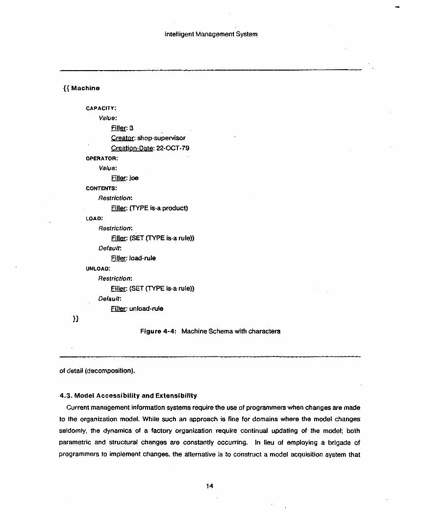
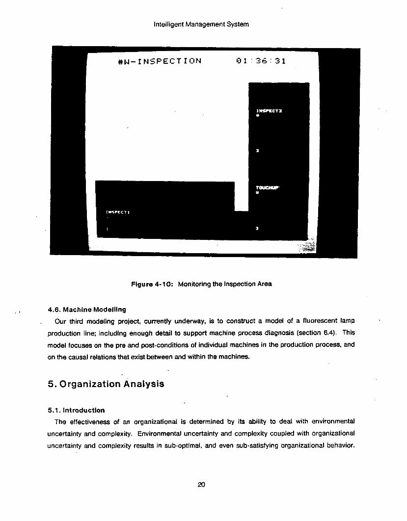
allows the user to specify what part of the plant to display. Figure 4-10 shows a blow up of the
inspection area. At 1 :36 there are 6 orders in the inspect1 station and 8 orders in the touchup station.
Process flow is defined by a production (operation) lineup defined for each product type. When an order is unloaded from an object such as a machine, work-area, etc. the next operation is determined
by information inherited by the object.. For some objects access to a scheduling system is inherited
via the PART-OF relation, for others the next operation is defined directly due to physical coupling of
operations.
'under design by the Westinghouse Corporation.
17

Intelligent Management System
. Sirnut at ion ’ Display
1 Is-A I ls-A . Continous Is-A I Concept Concept
,Simulation IS-A
L
b rn
Discrete 1-0 Display Simu-
Process lation - I IS-A IS-A 1 . IS-A
L I
Machine WORK c -1 AREA
IS-A 4 1
IS-A IS-A Drill -
Cold D e v e J o Room 8l
Mater ia l Drill Storage &
, Etch Route d
R o u t e r
NC IS-A Drill
Assigned to I
Assigned to $FA Em p lo y ee Male 1s-A HUMAN
Figure 4-8: Flow-Shop Partial Model

Intelligent Management System
Figure 4-9: Monitoring the Factory
4.5. Job-Shop Modelling
A model of part of a turbine component production plant4 has also been constructed to support
simulation (section 5.2) and job-shop scheduling functions (section 6.2). The model contains
information about machines, products, tools, work-centers, labor and cost data, and factory layout.
Much of the schemata used to model the circuit-board plant were used in the turbine plant model. In
some cases additional slots (attributes) were specified, e.g., cost data, and operation sequences were
expanded to operation graphs to include alternate processing routes in the plant.
~
4Westinghouse Turbine Component Plant, Winston-Salem NC.
19
Intelligent Management System
Figure 4- 10: Monitoring the Inspection Area
4.6. Machine Modelling
, Our third modeling project, currently underway, is to construct a model of a fluorescent lamp
production line; including enough detail to support machine process diagnosis (section 6.4). This
model focuses on the pre and post-conditions of individual machines in the production process, and
on the causal relations that exist.between and within the machines.
5. Organization AnaI.ysis
5.1. Introduction
The effectiveness of an organizational is determined by its ability to deal with environmental
uncertainty and complexity. Environmental uncertainty and complexity coupled with organizational
uncertainty and complexity results in sub-optimal, and even sub-satisfying organizational behavior.

. Intelligent Management System
To produce requisite behavior, an organization must analyze its environment and adapt. But it is too
often the case that management lacks the time or ability to carry out the analysis; hence the
organization internalizes more rigid behavior. One of the most important but least understood
aspects of an organization is its ability to adapt. Much of Organization Theory has been concerned
with determining environmental and task characteristics that affect organization structure (March 8
Simon, 1957; Galbraith, 1973; Williamson, 1975). At best the results are descriptive.
Tools do exist that aid in the analysis of organizations. In particular, a simulation system allows one
to test structure and processes. But the cost of constructing a simulation can be prohibitive, with the
resulting system being of little use except for running the same or similar simulations again. Simple
"what if" questions cannot be answered readily. A manager requires an intermediary, such as a
system analyst, to answer the question. There is a definite need for more sophisticated tools for
analyzing organizations, and for providing usable tools directly to the managers and professionals.
The following describes some of the research in IMS towards these goals.
5.2. Simulation
Many of the "what if" questions encountered in our analysis were concerned with the
understanding of structural changes in the factory. For example, the decision to buy a more flexible
but more expensive machine depends on its eFfect on the performance of the factory. In a job-shop, it
is difficult to answer question analytically due to the complexity of the model. Simulations are used to
predict the performance of complex systems. Hence they are a potentially useful tool to provide
managers with. Why do research in this area when systems like GPSS, Simscript, etc. already exist?
The reasons are many:
0 Current systems are difficult to learn to use and require extensive computer programming skill.
0 They suffer from the modeling problems described in the modeling section. '
0 Output is limited to the analysis provided by the system.
0 Most systems are not interactive, and cannot be monitored easily while they run.
A discrete simulation system has been constructed that interprets the organization model directly
(Reddy &. Fox, 1982). The model represents the complete organization, not just the information
necessary to perform a simulation. The simulation uses as little or as much of the model as it
requires. Hence the user only has to modify the general model without having to alter the simulation
21
Intelligent Management System
system. Some of the characteristics of the simulation system are:
0 It is interactive, allowing the user to start, halt, and resume the simulation.
0 The user can query the state of entities in the simulation as the simulation proceeds.
0 The organization is displayed on a color graphics device with pertinent data (e.g., queue sizes) changing as the simulation proceeds. The user may view the organization at several levels of abstraction as the simulation runs.
.The user can interactively alter the model while the simulation is in progress and the simulation will continue with the alterations.
0 The user can display a variety of analysis at the terminal.
0 It accesses the same organization model that other functions use. Hence, only one model is maintained in IMS.
The simulation system proper is small. Its sole purpose is to manage the event queue. How events
are interpreted is defined in the model. For example, a load event of the Pcoven (figure.4-6) would
be accomplished by evaluating the contsnls of the Pcoven's LOAD slot, which is inherited via the is-A relation from the Continuous-Machine schema (figure 4-5). The contents of an event slot is a set of
rules defining the event's behavior?
Data gathering for analysis is accomplished by associating data gathering rules with the
appropriate slots in the model. In particular, rules can be specified to be evaluated anytime the
contents of a slot are changed.
Simulation monitoring is handled in' the same manner as data gathering. Display rules are associated with slots in the model. When a slot value is changed, the associated rules are evaluated,
resulting in display changes.
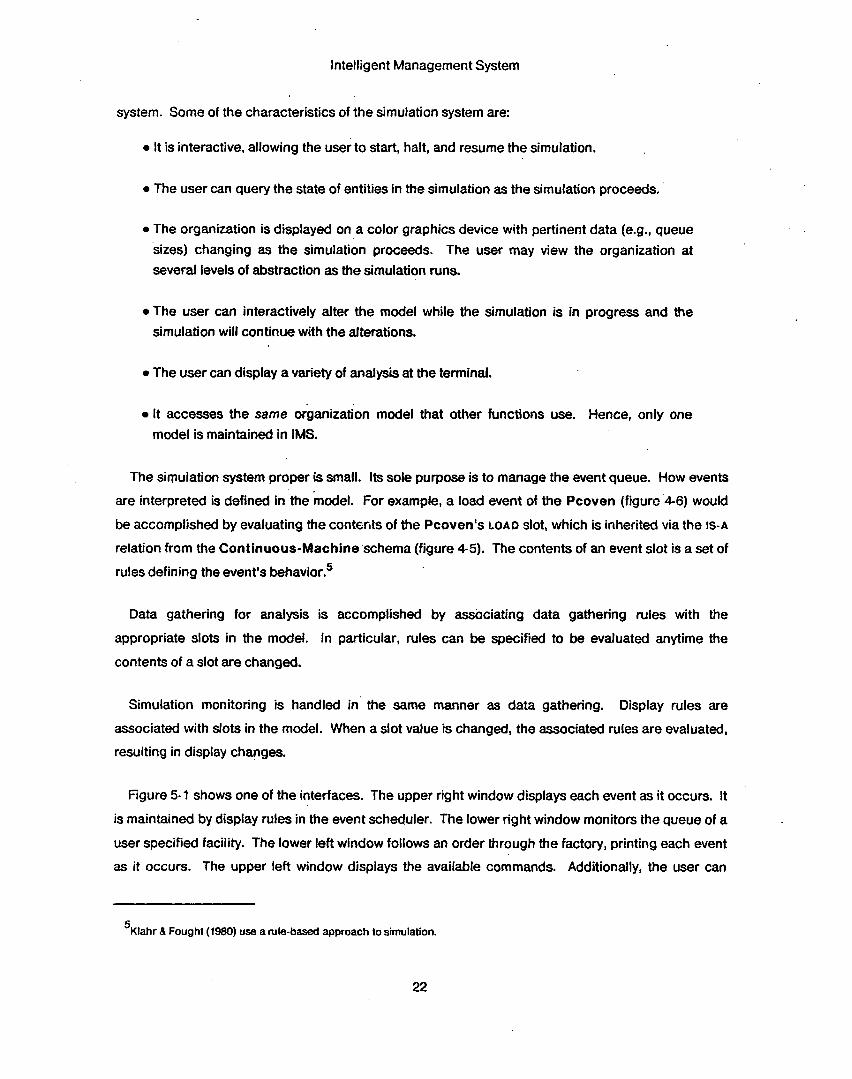
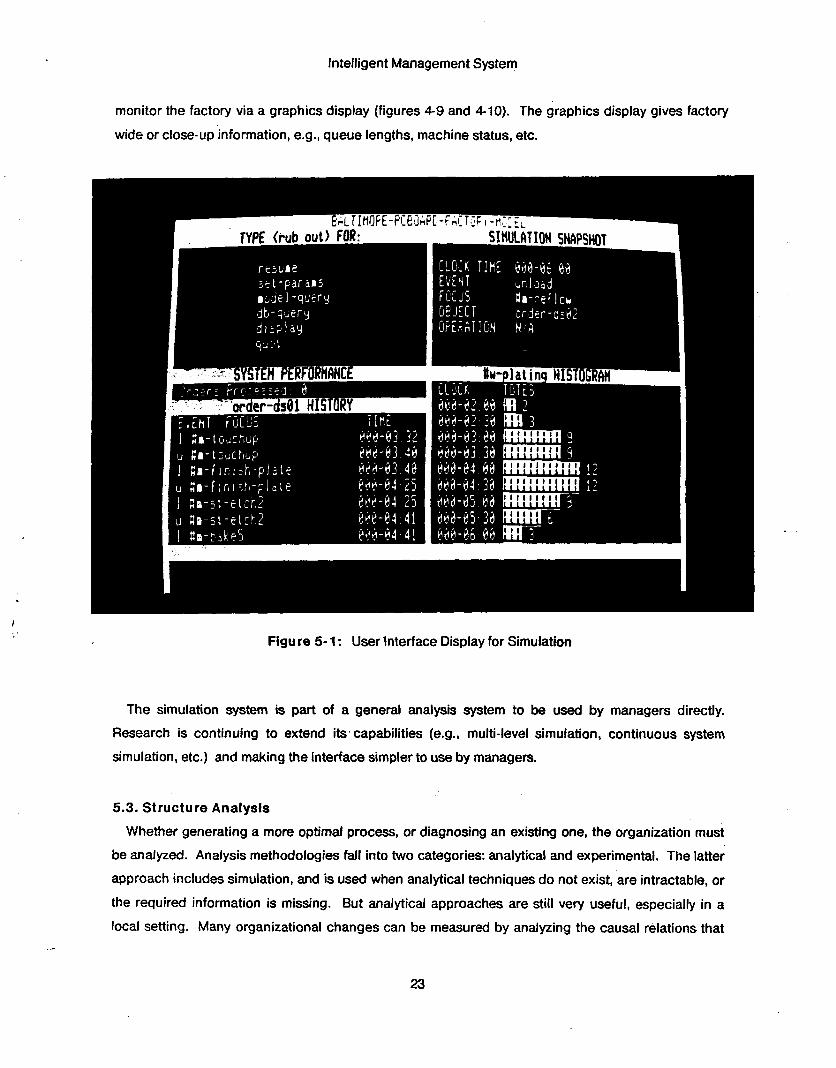
Figure 5-1 shows one of the interfaces. The upper right window displays each event as it occurs. It
is maintained by display rules in the event scheduler. The lower right window monitors the queue of a
user specified facility. The lower left window follows an order through the factory, printing each event
as it occurs. The upper left window displays the available commands. Additionally, the user can
'Klahr 8 Fought (1980) use a rule-based approach to simulation.
22
Intelligent Management System
monitor the factory via a graphics display (figures 4-9 and 4-10). The graphics display gives factory
wide or close-up information, e.g., queue lengths, machine status, etc.
Figure 5- 1 : User lnterface Display for Simulation
The simulation system is part of a general analysis system to be used by managers directly.
Research is continuing to extend its. capabilities (e.g., multi-level simulation, continuous system
simulation, etc.) and making the interface simpler to use by managers.
5.3. Structure Analysis
Whether generating a more optimal process, or diagnosing an existing one, the organization must
be analyzed. Analysis methodologies fall into two categories: analytical and experimental. The latter
approach includes simulation, and is used when analytical techniques do not exist, are intractable, or
the required information is missing. But analytical approaches are still very useful, especially in a
local setting. Many organizational changes can be measured by analyzing the causal relations that
23

Intelligent. Management System
exist “around“ the proposed change. ‘By following causal links and measuring their change effects,
most generated changes can be adequately tested. The generation of changes is dependent upon
the existence of causal or dependency information that can denote high expense areas measured by
some criteria.
In the laboratory, we are extending the organization modeling research to include organization
structure analysis. Our goal is to construct a system that can analyze an organization model and
suggest structural changes in order to improve performance as measured against some well defined
criteria such as profit, reaction time, and quality of output.
6. Organization Operation and Management
6.1. Introduction
The purpose of our research in organizalion operation and management is to provide intelligent
aids to managerial, professional and salaried staff. While the primary goal is to provide expert level
functionality, other factors must be considered. First, the aid must be interactive to allow access in a
timely fashion. It must be integrated with the rest of IMS so that it can access available information
and functions, communicate with other users, their UPS, TMPs, and MSPs. Just as important, the aid
must be constructed in a manner that its declarative and procedural knowledge can be easily altered
and expanded. In order to achieve these goals research from artificial intelligence, computer
science, and management science have been used in the construction of th& aids.
6.2. Job- Shop Scheduling
One of the most important functions in a factory is scheduling. Simply, scheduling is a resource
assignment problem which is constrained by resource availability of one form or another and
organizational goals in a jbb-shop. Scheduling in a job-shop is a problem because there is more than
one way of producing an item, and that all orders are competing for the same resources (machines,
personnel, materials, tools, etc.). In the factories we are working with, there are several thousand
distinct product models. At any given time, there could be between one and several hundred
duplicate units of a particular product model on the floor. There are many alternative routes that each
product model could travel through the factory, depending on the availability of physical production
resources, other active orders on the floor, and on the relative importance of time, cost and other cost
constraints.
Job-shop flexibility is only part of the problem, dynamically changing factory status is another.
24

Intelligent Management System
Although the physical number of machines in the plant, or the number of operators employed does
not change too often, the set of machines, tools, and workers that are actually available at a given
moment is constantly changing. Machines break down often, at unpredictable times. 'A worker may
get hurt and have to leave the shop floor, leaving the machine unattended. Small tools may disappear
because the operator forgot to return them to the tool crib, or lent them to someone else without
recording it.
Existing job-shop scheduling systems, for the most part, are inflexible. They are based on a "static"
model of critical production resources, based on the number of machines, tools and workers which
are available under "ideal" conditions, and not on the set of production resources which are actually
available at a given moment. These "static" models can not be modified at the rate at which changes
occur. As a result, these systems are limited in their usefulness, since there are few times when the
"static" model inside the computer matches actual operating conditions. Many factories which
currently have these types of systems srill have to schedule manually because of the frequent
changes in operating conditions.
Another, more important, problem with existing scheduling systems is that they do not account for
all the constraints that human schedulers use in manually constructing schedules. Interviews with
schedulers and other factory personnel has shown that they receive information from more than 20
sources in the plant, such as forging, tooling, NC programming, and materials, marketing, and
forecasting. Much of the scheduler's time (80%) is spent gathering these constraints, and then
constructing a schedule that satisfies as many of the constraints as possible. Hence, the problem of
scheduling can be viewed as the problem of constraint satisfaction.
An interactive, real-time, job-shop scheduling/operations control system has been constructed
which interprets the factory model dirwtly. It is called ISIS: Intelligent Scheduling and Information
System'. It schedules orders on machines for complex job-shop environments where orders require
a large number of operations, and there are many different ways of producing an order on machines
under high contention. It allows the user to enter orders and specify scheduling constraints. Existing
constraints include:
0 start and due dates
0 operations costs 8
0 operation alternatives
61S134 was demonstrated in December 1980 at CMU, a second version, ISIS-II was demonstrated in December 1981.
25
Intelligent Management System
0 machine alternatives
0 machine down-time and maintenance
0 order priorities
0 order lottings
0 lot priorities
0 work in process levels
0 production goals
0 shop stability requirements
0 machine productivity
0 shifts available
0 resource availability
0 machine attributes
0 operation requirements
The system will generate a schedule that attempts to satisfy the constraints. The system uses a
constraint-based heuristic search to construct forward (from start date) or backward (from due date)
plenned schedules. Constraints are not built into the algorithm, but are part of the factory model. The
user can add, alter, and remove constraints. lSlS dynamically resolve what constraints to use and
where to use them during the scheduling process. The scheduler is a factory floor level system which
updates its factory model (e.g., machine, order, personnel, resource status) either by user ‘input or
through computer messages. And the system does a minimal rescheduling in reaction to any state
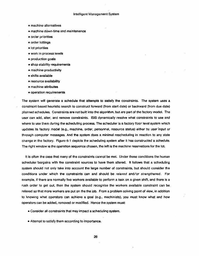
change in the factory. Figure 6-1 depicts the scheduling system after it has constructed a schedule.
The right window is the operation sequence chosen, the left is the machine reservations for the lot.
.
It is often the case that many of the constraints cannot be met. Under these conditions the human
scheduler bargains with the constraint sources to have them altered. It follows that a scheduling
system should not only take into account the large number of constraints, but should consider the
conditions under which the constraints can and should be relaxed and/or strengthened. For
example, if there are normally five workers available to perform a task on a given shift, and there is a
rush order to get out, then the system should recognize the workers available constraint can be
relaxed so that more workers are put on the the job. From a problem solving point of view, in addition
to knowing what operators can achieve a goal (e.g., machinists), you must know what and how
operators can be added, removed or modified. Hence the system must:
0 Consider all constraints that may impact a scheduling system.
0 Attempt to satisfy them according to importance.
26

Intelligent Management System
Figure 6- 1 : Scheduling System
e Decide when constraints should be relaxed.
0 Choose whar constraints should be relaxed.
e Decide how to relaxathe constraint.
ISIS-II can and does selectively relax a subset of constraints. An new version, ISIS-Ill, is under
development. It will have the capability to relax any constraint. The research emphasis of this system
is to extend the general representation and utilization of constraints, and on how these constraints
can be dynamically relaxed.
27

Intelligent Management System
6.3. Factory Monitoring
As discussed in the section on simulation, the display facilities used to monitor the simulation are
attached to the model. Hence, if the model is updated from real-time messages from the factory floor,
as opposed to the simulation, figures 49,410, and 5-1 can be used to monitor the real-time operation
of an organization.
6.4. Process Diagnosis
Complex production environments may introduce a variety of defects into a product. The defect
may not appear until later in the production process, where cumulative processing compounds the
earlier induced defect to a point where signs of its manifestation appear. The purpose of process
diagnosis is to understand each step of the production process to determine what type of problems
can occur and the causal (cumulative) relations that can exist amongst sequential steps in the
production process. The goal is to construct a system that monitors the production process, and
when defects occur, analyze the problem to determine the possible points in the production process
which could have caused it. A machine group'. monitoring, signalling, and control system has been
designed, and the prototype simulation has been demonstrated. Our next step is to construct a
training simulator for new operators, before completing the diagnosis system. The rational for this
multi-step approach is both pragmatic and theoretical. The group does not contain adequate
sensoring to support diagnosis at present, but new senors will be added over the life of the project.
The simulator project, when completed, will provide the group model for the diagnosis project.
7 . User Interfaces
7.1. Introduction
An obstacle preventing the introduction of intelligent systems into organizations is the lack of
reasonable interfaces. The keyword here is reasonable. The reasonableness of an interface is not
absolute. It depends upon the person accessing the system: knowledge of the system, expectations,
time constraints, etc.; the style of the interface: menu, touch screen, voice, typing, interactive, batch,
and the functionality of the system. Successful systems tend to constrain the expectations of the
user, and then optimize the interface for the constrained task (e.g., ZOG (Robertson et al., 1979),
DAISY (Buneman et al., 1977)).. This is sufficient when the task itself is naturally constrained, e.g.,
sales order entry, inventory control. But many of the ill-structured tasks that managers do, e.g.,
7A machine group is a set of machine integrated into a automated flow shop. The machine group produces fluorescent bulbs.
28
Intelligent Management System
planning, forecasting, are not well enough understood, let alone highly constrained. If the goal is to
introduce intelligent aids at the professional and managerial level, then the interface’s acceptability
will increase as the interface closely approximates typical human interactions.
The purpose of our user interface research is to explore the problem of interfacing people with
machines by incorporating dialogue and problem-solving capabilities in the UIP. During the first year
of the project, research focused on modeling, managing and analysis functionality. Little was done in
the area of user interfaces. Since then our emphasis has shifted to include interfaces. The following
describes both our accomplishments and goals.
7.2. Information Display
In a multiple process environment, monitoring more than one process can be difficult when using
only a single display. Previous solutions to the problem entailed programming each process to
cooperate in the use of the display, essentially hard-wiring their interaction. Changes in processes,
information to be displayed, etc. required each process’s display code to be altered. We have solved
the problem by providing a communication and display system that allows processes to communicate
icformation for display, independent of who is to receive it and the device upon which it is to be
displayed. This allows a process to dynamically communicate with any other process and have the
communication appear on a screen in conjunction with information from other processes; without
interference or recoding (see figure 5-1).
7.3. Natural Language Interface The goal of accessibility can only be achieved if users are able to communicate with computers in a
language that is natural to use. An obvious candidate is English. Over the last 20 years, researchers
in artificial intelligence have constructed natural language understanding (NLU) systems that allow
users to type English statements and questions into the computer. The state of natural language
understanding research does not allow. the computer to understand arbitrary sentences; they must be
restricted to a particular task or domain. But, research continues to expand the capabilities of such
systems.
In IMS, simple, constrained, English input is being experimented with. Two tasks have been
chosen, model building and scheduling, to explore the use of natural language interfaces. Using the
parsing system of Carbonell & Hayes (1981), a grammar for scheduling has been constructed and is
being tested.
29
. Intelligent. Management System
7.4. Explanation
Much of the failure of computer systems can be ascribed to their inability to account for their
results. Once the output is produced, the user cannot delve into ,how results were produced without
reading the computer program. Since many end users are not programmers, this is intolerable.
An explanation facility provides the means by which a user can investigate how results were
‘derived, why a particular action was executed, or what the current state of the system is. The
explanation facility is a natural language generating system which is able to maintain a discourse
centered around analyzing a particular action or state. The purpose of NLU is to translate English
sentences into a representation that the machine understands. The explanation system describes the
machine’s reasoning processes upon request.
7.5. Discourse Modelling
The act of describing an organization can,be quite complex from a natural language understanding
point of view. Not only must each sentence be understood, but ideas communicated earlier are
continually referred to directly and indirectly. Consider the following description:
There is an inspection area. It seats 12 inspectors. They have a desk, magnifying lamp and a terminal. The room is next to the cold room
In order for the UIP to carry out a conversation, it must track the flow of ideas, bind referents, watch
for and signal inconsistencies, etc. This ability is referred to as discourse modeling.
7.6. Planning
The true mark of intelligence in management systems is the ability to use the best information and
apply the best methods in answering a user request. Consider the task of determining the effect of
adding or changing a machine in a job shop. There may be many ways of doing this such as statistical analysis, simulation, and looking at similar situations. Deciding exactly how to measure the
effect is a planning process, where a sequence of tests and actions must be constructed to arrive at
an answer. This sequence is chosen from a set of competing methods. Planning requires knowledge
of what tools are available, how effective they are, and the conditions under which they are to be
used. Using a tool may require planning the use of other tools to provide the required conditions. For
example, before doing a simulation, a model must be constructed, and initialization data be gathered.
If the user interface is to act as an intelligent aid, it must be able to extend the user’s capabilities by
30
Intelligent Management System
determining the most appropriate means to implement the user's request or command. The planning
mechanism examines the data and functions known to it and constructs a plan whose execution
accomplishes the task.
7.7. Personalization
The user interface process can be viewed as an extension of the user. But users differ in a variety
of ways: task prescription and language of communication for example. The UIP must know the user
in order to amplify or restrict the user's capabilities according to their position in the organization.
Consider the machine operator. He should be able to communicate with his UIP using the vocabulary
of his task, he should be able to provide status information, and request scheduling information, but
he should be restricted from finding out the plant manager's salary.
8. Integrating Distributed Systems Research is proceeding in the flexible integration of the multiple functions of the Intelligent
Management System. As described in section 2, IMS will be comprised of processes of type UIP, MSP
and TMP8. These processes will run on processors spread throughout the plant and are connected
by a communication network (figure 3-1). Any process may dynamically spawn other processes
according to its problem-solving needs. For example, a scheduler's UIP may have to analyze the
effect of alternative priority ratings on orders over the next year. The UIP first determines how the
question can be answered. It communicates with a module librarian process (TMP) to see if there are
any modules in IMS that may help in answering the question. There is a module called "simulation"
that can simulate a discrete-event model over time. It also finds that there are modules that can
instrument a model to gather data over time. And a module that can analyze time-series data. The
UIP acquires the module definitions from the librarian and spawns as many processes as needed to
execute them. Knowledge of what modules are available to solve a problem or answer a question is
not programmed into a module, but is part of a module's goal description which is accessible by other
modules in the system. This is in the tradition of stimulus-response frames of Hearsay-I1 (Hayes-Roth
& Lesser, 1977).
The key points in this organization of processes are:
1. Modules have been created that provide generic functionality.
'Versions of IMS have been created with multiple MSPs being simulated, and communicating with a UP. Also UlpS for scheduling and organization analysis have been created.
31

Intelligent Management System
2. Modules are described in a machine interpretable manner.
3. Processes have problem-solving capabilities that allow them to determine what modules are appropriate to solve a problem or answer a question.
4. Processes can communicate needs and information.
A language for describing both software system architectures and individual modules has been
created (Fox, 1979b). ODL (Organization Design Language) can be used to define module
capabilities, resource usage, goals, and the system architecture. By describing IMS tasks and tools
(modules) with ODL, processes can reason about module and system applicability to problem
situations. Additionally, a simple information protocol has been developed to allow processes to
request and provide information.
In addition to function availability, data accessibility is important to maintaining system flexibility..
When a module is instanced as a process, a process schema (description) is created, defining who
created the process and what rights it has in the current environment. A process has its own local .
data space which contains the information necessary to carry out it’s task. When a process requires
information not defined locally, it uses its process schema and the module descriptions cf other
processes to determine where the information may reside. Once having determined accessible
processes, it sends messages requesting the information. Upon receipt of the information, it is
cached in the process’s local data space. This technique has been used by the simulation system to
acquire only the parts of the factory model it needs for a simulation.
9. Conclusion Most of the costs of producing products in complex organizations are attributed to overhead, much
of which is comprised of managerial, professional, and salaried personnel. If significant productivity
gains are to be made in this decade, more attention must be paid to aiding both the professional and
the manager. The Intelligent Management System is a step towards this goal. By combining artificial
intelligence, computer science, and management science techniques, more intelligent aids and
solutions for the operation and management of complex organizations can be found.
This article provides an overview to the Intelligent Management System. It provides a glimpse into a
goals and the systems we are creating and have created to date. In the area of organization modeling
we have completed a second version of an interactive organization design system and have applied it
to the modeling of three plants. In organization operations, we have created the second version of a
32

Intelligent Management System
constraint-based job-shop scheduling &d control system and our about to install it in a test site. And
in organization analysis, we have created an interactive simulation system which uses the same
model as scheduling. Each of these working applications represent a piece of an evolving Intelligent
Management System.
10. Acknowledgments IMS is the result of the efforts of many people in the Intelligent Systems Laboratory. They include
Brad Allen, Don Cohen, Bryan Griffin, Jenny Hood, Carol Johnson, Joe Mattis, Drew Mendler, Steve
Miller, Tom Morton, Ramana Reddy, Gary Strohm, Ari Vepsalainen, and Mark Wright. I also wish to
thank Jaime Carbonell, Bill Ferguson, and John McDermott for their comments on earlier drafts of this
report.
, . 11. References
Alter S.L., (1 W), Decision Support Systems: Current Practice and Continuing Challenges, Reading, MA: Addison-Wesley Pub. Co.
American Machinist, (1980), "Machine Tool Technology", American Machinist, Vol. 124, No. 10, Oct. 1980, pp. 105-128.
Bartlett F.C., (1932), Remembsiing, Cambridge: Cambridge University Press.
Bobrow D., and T. Winograd, (1977), "KRL Knowledge Representation Language," Cognitive
Science. Vol 1, No. 1, 1977.
Buneman O.P., H.L. Morgan, and M.D. Zisman, (1977), "Display Facilities for DSS Support: The DAISY Approach", Proceedings of a Conference on Decision Support Systems, SIGBDP, Vol. 8, No. 3, 1977.
Carbonell J., and Phil Hayes, (1 981), "Multi-Strategy Construction-Specific Parsing for Flexible Data Base Query and Update", Proceedings of fhe Seventh lnternational Joint Conference on Artificial Intelligence, Vancouver B.C., Canada, August 1981.
CMU-CSD, (1 979), "Proposal for a Joint Effort in Personal Scientific Computing", Computer Science Department, Carnegie-Mellon University, Pittsburgh PA.
Duda R.O., P.E. Hart, P. Barrett, J.G. Gaschnig, K. Konolige, R. Reboh, i d J. Slocum, (1978),
"Development of the Prospector Consultation System for Mineral Exploration: Final Report", Tech. Rep., SRI International, Menlo Park CAI Oct. 1978.
33
Intelligent Management System
Erman L.D., F. Hayes-Roth, V.R. Lesser, and D.R. Reddy, (1980), "The Hearsay-II Speech- Understanding System: Integrating Knowledge to Resolve Uncertainty", . Computing Surveys, Vol. 12, No. 2, June 1980, pp. 213-253.
Fox M.S., (1 979a), "On Inheritance in Knowledge Representation", Proceedings of the Sixth International Joint Conference on Artificial Intelligence, Tokyo Japan.
Fox M.S., (1 979b), "Organization Structuring: Designing Large, Complex Software", Technical Report CMU-CS-79-155, Computer Science Department, Carnegie-Mellon University, Pittsburgh, PA.
Fox M.S., (1 982), "SRL: Schema Representation Language", Technical Report, Robotics Institute, Carnegie-Mellon University, Pittsburgh PA, in preparation.
* .
Galbraith Jay, (1 973), Designing Complex Organizations, Addison-Wesley.
Hayes-Roth F., and V. Lesser, (1977), "Focus of Attention in the HEARSAY4 Speech Understand System,'' Fifth Int. Joint Conf. on Artificial Intelligence, Cambridge, MA, Aug. 1977.
Klahr P., and W. Faught, (1980), "Knowledge-Based Simulation", Proceedings of fhe First Annual National Conference on Artificial Intelligence, Stanford CA, Aug. 1980, pp.
- _
181 -183.
Lenat, D., (1976), "AM: An Artificial Intelligence Approach to Discovery in Mathematics as Heuristic Search," (Ph.D. Thesis) Computer Science Dept., Stanford University.
Lowerre B., (1976), The HARPY Speech Recognition System, (Ph.D. Thesis), Tech. Rep., Computer Science Dept., Carnegie-Meilon University, Pittsburgh PA.
March J.G., and H.A. Simon, with H. Guetzkow, (1958), Organizations, New York: John Wiley kmd Sons.
McDermott J., (1980), "R1: an Expert in the Computer Systems Domain", Proceedings of the First Annual National Conference on Artificial Intelligence, Stanford University, Aug. 1980, pp. 269-271.
Minsky M., (1975), "A Framework for Representing Knowledge", In The Psychology of Computer Vision", P. Winston (Ed.), New York: McGrawLHill.
Pople H., (1977), The Formation of Composite Hypotheses in Diagnostic Problem Solving: An Exercise in Synthetic Reasoning. Proceedings of the Fifth International Joint
34
Intelligent Management System
Conference on Artificial Intelligence, Cambridge, Aug. 1977.
Rashid R.F., (1 m), "An interprocess communication facility for UNIX", Technical Report CMU- CS-80- 124, Computer Science Department, Carnegie-Mellon University, Pittsburgh PA, February 1980.
Reddy Y.V., and M.S. Fox, (1982), "Knowledge-Based Simulation", Technical Report, The Robotics Institute, Carnegie-Mellon University, Pittsburgh PA.
Robertson G., D. McCracken, and A. Newell, (1981), "The ZOG Approach to Man-Machine Communication", lnternational Journal of Man-Machine Studies, Vol. 14, pp. 461 -488.
Shortliffe E.H., (1 976), Computer-Based Medical Consultations: MYCIN, New York: American Elsevier.
Simon H.A., (1960), The New Science of Management Decision, New York: Harper and Row.
Williamson O.E, (1 975), Markets and Hierarchies: A Transactional and Antitrust Analysis of the Firm, New York NY: The Free Press.
1. System Particulars IMS is programmed in Franz-lisp on a VAX-11/780 running the UNIX operating system. Processes
communicate using the Interprocess Communication Facility (Rashid, 1980). The color display is a
Grinnell system.
35
