the effect of passing tehran subway’s train wheels on ... · the effect of passing tehran...
TRANSCRIPT
The effect of passing Tehran Subway’s train wheels on fatigue life of rail’s joints
M. Saket 1
1 . University Lecturer, Department of Railway Engineering, Iran University of Science and Technology, Narmak,16846, Tehran, Iran
Metro-System manager, Pajoohesh Consulting Engineer, Qolhak, 15134, Tehran, Iran
E-mail: [email protected]
Abstract: In this article, railway joints fatigue life and effective factors on it are investigated. Full explanation of rail joint’s fatigue and the related factors are presented in the beginning of the paper. A finite element analysis is conducted to study static and dynamic elasto - plastic stress through passing a wheel on a mechanical rail joint with gap between the two rail parts of joint. Using ANSYS and LS-DYNA software are coupled to simulate the process of the wheel contacting or impacting the rail joint. 3D surface to surface contact elements are used to simulate the interactions between wheel and rails, between rails and fishplates. Using Experimental test data verified dynamic and static simulation result. The effects of Tehran’s metro train speed, axle load, gap length, and wheel hardness on the contact forces, stresses and impact ratio at railhead, are investigated. The results indicate that the axial loads have a larger effect on the contact force, stress and impact ratio than the train speed in normal joints. Key words: Tehran Subway, Railway joints, impact loading, fatigue, dynamic simulation, wheel contact
1. Introduction Among all the sub-systems and the components that are a part of a railway system, the wheel/rail interface is one of the most delicate, both as regards the performances of the train and as regards its safety. Through the wheel/rail interface, in fact, the dynamic and static loads pass from the rail and rail joints to the wheel through a really small contact area, whose extension and geometry can vary during the passing and impacting.
The behavior of the wheel/rail interface is fundamental for guaranteeing adequate comfort and stability during the train trip and it is also very important for guarantying a sufficient level of safety to the train. Ride comfort index in each kind of transportation has much importance. In urban railway transportation system, smooth moving on rails disturbs by passing on joints. Recently the rail joints are being eliminated by the introduction of the continuously welded rails in many countries. However, rail joints still exist in the shunting yards and some part of Tehran metro’s way. Also the combination of weld and mechanical joints has been used to decrease the disturbance due to this gap in some tracks. Now there are a large number of rail joints in sub urban lines and urban railway in Iran and other areas and in maintenance and marshaling yards. Two fishplates and six or four bolts are used to connect the ends of two part of rails. This mechanical joints and fishplates is to line-up rail ends horizontally and vertically and to create smooth running surface for rolling contact of wheels on rails. But the existence of rail joint with rail gap’s length, height difference, dip angle and loose bolts breaks the slickly of track.
Because of the existence of these defects at mechanical rail joints, these rail joints will subjected to abnormally high dynamic impact forces and stress when the wheels pass over it. Derived from field survey [1], impact forces caused by normal rail joints range from 2 to 3 times of the static load between the wheel and rails, and even 5 times in some cases.
Some large impact forces between the wheel and rail’s head cause severe rail damages, such as squashing, spalling, wear and cracks, in rail joint region than in other regions [21].
Damage accumulation due to fatigue, impact loads and plastic deformation during passing
the wheel, significantly reduces the service life of the rail joints. In recent years, higher train speeds and increased axle loads have led to larger wheel impact load in joints. Also, efforts have been made to optimize designing of rail joints or omitting them by new joint technology. This procedure tends to change the major rail head damage from break to fatigue [22]. Unlike the slow destroy process of fatigue, causes abrupt fractures in rail head or rail surface material loss. These failures may cause damage to rails and joints, damage to train suspensions, damage to super structure, damage to wheel profile and, in rare cases, serious derailment of the train.
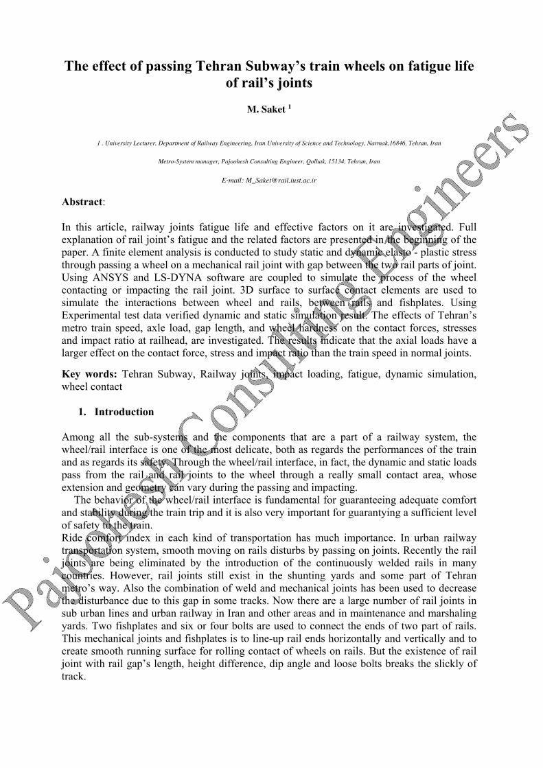
Figure 1 Rail/ Wheel interaction during passing Rolling Stock on normal rail
The statistics from the railroad field shows that many of replacing rails due to breakages of
rail joint accounts for a significant 50% of the total replacing rails [16]. Chen and Chen [9] studied the effect of insulated rail joint on the distributions of wheel/rail normal and tangential contact stress and maximum shear stress under the condition of partial slip using a 2D finite element method. Their results presented that the insulated rail joint might significantly affect the wheel/rail contact stress distributions.
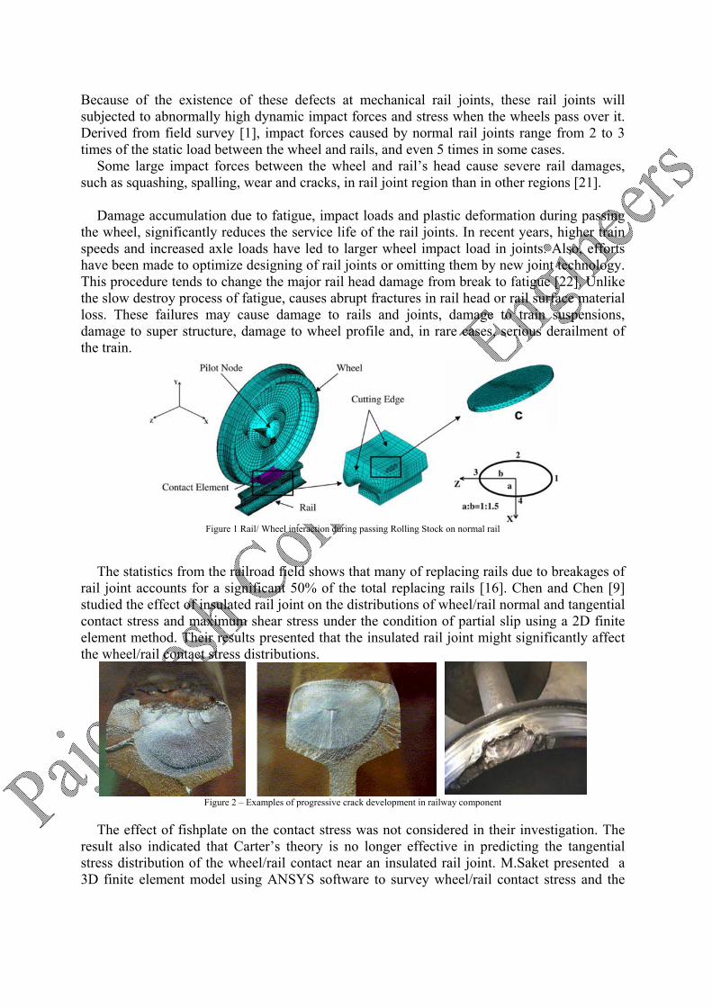
Figure 2 – Examples of progressive crack development in railway component
The effect of fishplate on the contact stress was not considered in their investigation. The result also indicated that Carter’s theory is no longer effective in predicting the tangential stress distribution of the wheel/rail contact near an insulated rail joint. M.Saket presented a 3D finite element model using ANSYS software to survey wheel/rail contact stress and the
effect of hardness, axial load and lateral displacement of wheel on total stress at railhead and wheel [20], the results indicated that hardness and displacement of wheel may led to over stress at rail head.
In this survey, a three-dimensional (3D) elasto plastic finite element model used forward to study dynamic stress and dynamic impact, when a wheel passing over a rail joint by changing the wide gap, material parameters, axial load and train speed.
Wear, rolling contact fatigue, impact loads and thermal fatigue are the most common types of damage due to the wheel/rail contact and impact. All them are complex phenomena and only recently, thanks to the increased computational potentiality offered by modern computers and software, some successfully tentative of defining methods to understand how damage occurs and to predict its evolution have been developed.
2. FEM modeling
Because of some consideration, two type of modeling carried out in this investigation. At first statistical modeling in ANSYS software by definition of surface to surface of wheel/rail in normal condition obtained. Modeling the rail’s gap and static loading in second stage performed.
Dynamic modeling of passing the wheel on rail’s gap in LS-Dyna software prepared. Different wide gap length and very fine meshing in this stage led to high accurate results. In this stage two part of modeling prepared as below:
2.1.Statistic Simulation ANSYS 11.0 software to simulate static loading on rail and rail joint have been used. In this part, a 3D finite element model for wheel/rail rolling contact analysis is developed.
In order to have more accurate contact analysis, geometry profile of the rail head section and the wheel tread are very important. For this reason UIC54 and 60 1 section profile (for the
rail) and standard wheel profile2 is used [20, 21]. The rail’s length is a little more than the distance of two sleepers. Fixed boundary conditions3 are applied to the two area of cross section at the ends of the rail, used 2D Solid42 for surfaces, 3D Solid45 Element for modeling the wheel/rail volume and Target 170, Contact 175 contact element for modeling the Surface to Surface contact.
1 two prevalent rail section, recommended by UIC (International Union of Railways) 2 TML Tehran Urban railway coach type 3 All degree of freedom
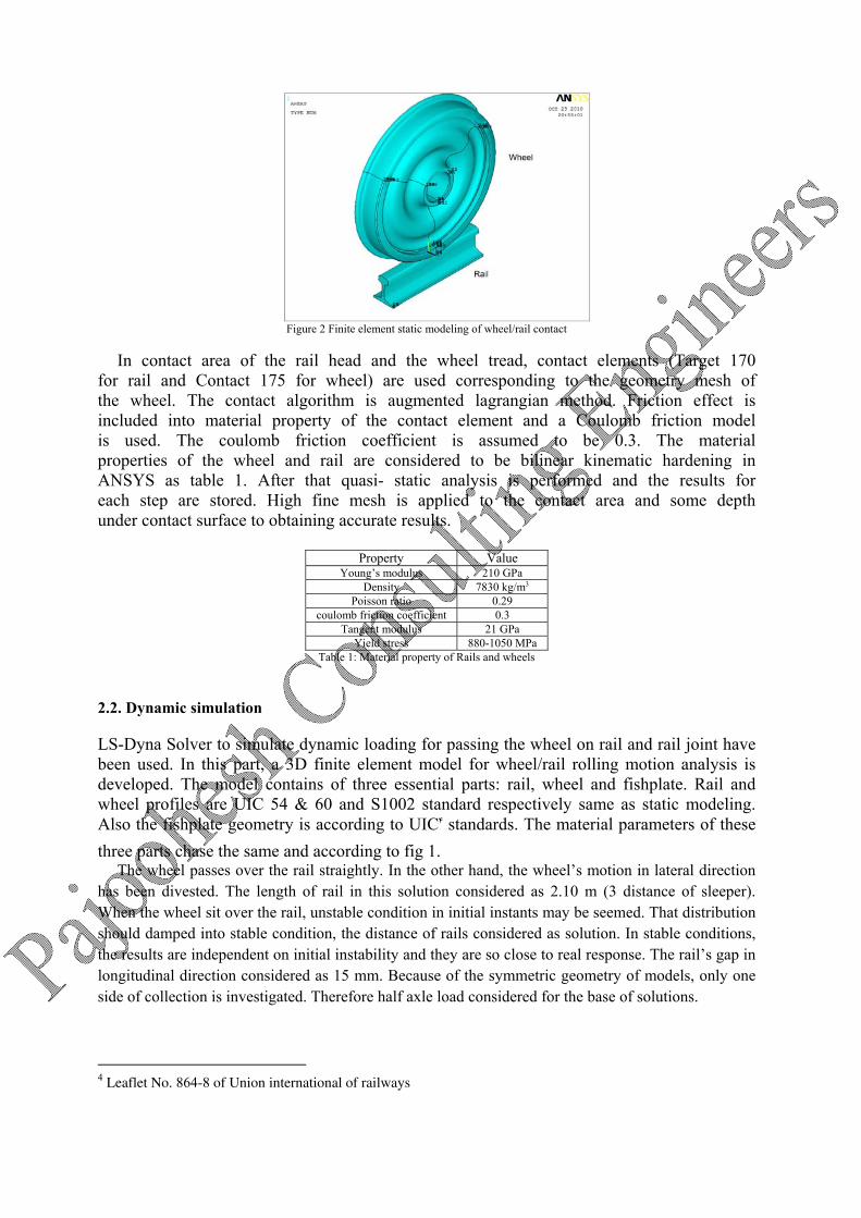
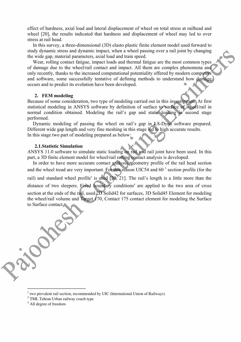
Figure 2 Finite element static modeling of wheel/rail contact
In contact area of the rail head and the wheel tread, contact elements (Target 170 for rail and Contact 175 for wheel) are used corresponding to the geometry mesh of the wheel. The contact algorithm is augmented lagrangian method. Friction effect is included into material property of the contact element and a Coulomb friction model is used. The coulomb friction coefficient is assumed to be 0.3. The material properties of the wheel and rail are considered to be bilinear kinematic hardening in ANSYS as table 1. After that quasi- static analysis is performed and the results for each step are stored. High fine mesh is applied to the contact area and some depth under contact surface to obtaining accurate results.
Property Value
Young’s modulus 210 GPa Density 7830 kg/m3
Poisson ratio 0.29 coulomb friction coefficient 0.3
Tangent modulus 21 GPa Yield stress 880-1050 MPa
Table 1: Material property of Rails and wheels
2.2. Dynamic simulation
LS-Dyna Solver to simulate dynamic loading for passing the wheel on rail and rail joint have been used. In this part, a 3D finite element model for wheel/rail rolling motion analysis is developed. The model contains of three essential parts: rail, wheel and fishplate. Rail and wheel profiles are UIC 54 & 60 and S1002 standard respectively same as static modeling. Also the fishplate geometry is according to UIC4 standards. The material parameters of these three parts chase the same and according to fig 1.
The wheel passes over the rail straightly. In the other hand, the wheel’s motion in lateral direction has been divested. The length of rail in this solution considered as 2.10 m (3 distance of sleeper). When the wheel sit over the rail, unstable condition in initial instants may be seemed. That distribution should damped into stable condition, the distance of rails considered as solution. In stable conditions, the results are independent on initial instability and they are so close to real response. The rail’s gap in longitudinal direction considered as 15 mm. Because of the symmetric geometry of models, only one side of collection is investigated. Therefore half axle load considered for the base of solutions.
4 Leaflet No. 864-8 of Union international of railways
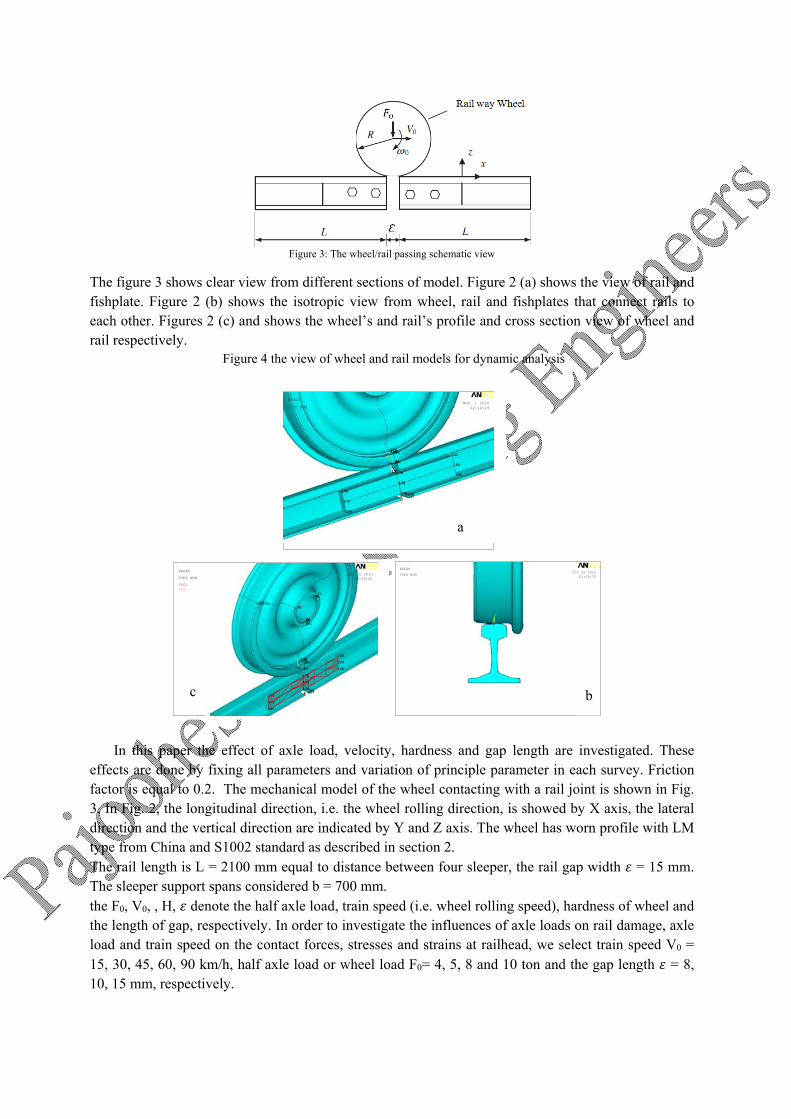
Figure 3: The wheel/rail passing schematic view
The figure 3 shows clear view from different sections of model. Figure 2 (a) shows the view of rail and fishplate. Figure 2 (b) shows the isotropic view from wheel, rail and fishplates that connect rails to each other. Figures 2 (c) and shows the wheel’s and rail’s profile and cross section view of wheel and rail respectively.
Figure 4 the view of wheel and rail models for dynamic analysis
In this paper the effect of axle load, velocity, hardness and gap length are investigated. These effects are done by fixing all parameters and variation of principle parameter in each survey. Friction factor is equal to 0.2. The mechanical model of the wheel contacting with a rail joint is shown in Fig. 3. In Fig. 2, the longitudinal direction, i.e. the wheel rolling direction, is showed by X axis, the lateral direction and the vertical direction are indicated by Y and Z axis. The wheel has worn profile with LM type from China and S1002 standard as described in section 2. The rail length is L = 2100 mm equal to distance between four sleeper, the rail gap width = 15 mm. The sleeper support spans considered b = 700 mm. the F0, V0, , H, denote the half axle load, train speed (i.e. wheel rolling speed), hardness of wheel and the length of gap, respectively. In order to investigate the influences of axle loads on rail damage, axle load and train speed on the contact forces, stresses and strains at railhead, we select train speed V0 = 15, 30, 45, 60, 90 km/h, half axle load or wheel load F0= 4, 5, 8 and 10 ton and the gap length = 8, 10, 15 mm, respectively.
1
3 4 3 4 4 3
93
92
97 96
103 109 108 115
114
118
89
93 91 97
103 111 109 105 115
99
167 168 167 168 168 167
171 172
173
174 178
179
180
171 172
178
172
173
179
178
173
174
180
179
174
180
171
183
184
185 171 172
183
172
173
184
183
173
174
185
184
174
185 171
X
Y
Z
NOV 1 201002:14:19
AREAS
TYPE NUM
1
3 4 3 4
17
4 3
17
70 70
17
70 70 70
17 17 74 17
70 75
78
17 74 85 84
75 81
93
92
96
103
102
82
109 108 115 114
140 139
74 85
144 143
89
93
147 146
91
149
83
103
153
111 109
105 115
157
167 168 167 168 168 167
172
173
174
178
179
180
172
178
172
173
179
178
173
174
180
179
174
180
183
184
185
172
183
172
173
184
183
173
174
185
184
174
185 X
Y
Z
DEC 2 201000:19:21
AREAS
TYPE NUM
PRES100
1
97 118 97 99 X
Y
Z
OCT 29 201021:04:35
AREAS
TYPE NUM
a
b c
The fishplate extensive load derived from the bolt pretension or preload can be defined experimentally, where Pb is the bolt pretension, T is the bolt torque moment, D is the bolt diameter, and K is the coefficient of the bolt torque moment, K = 0.19–0.25, selected T = 500 N m, D = 24 mm and K = 0.2 [16]. By crossing the quantity of bolts and dividing the result in fishplate surface, extensive load of fishplates derived. 3. Experimental tests
The experimental technique used with this aim is the confirmation of simulation and results in dynamic and static modeling that permits the measurement of the elastic strains. In these tests a loaded rail by observing strain at rail web. Through a complete actual test and installing the stain gauge through rail web, permits to evidence the influence of passing the rail way wheels on rails.
In this test, metro5 coaches in main marshaling yards6 (Fig4.) used for experimental test. TML china standard for wheel profile and UIC 54 rail profile utilized for these test. All the procedure divided to 3 major tests as described below:
Static test Dynamic test with constant speed Dynamic test with acceleration or deceleration
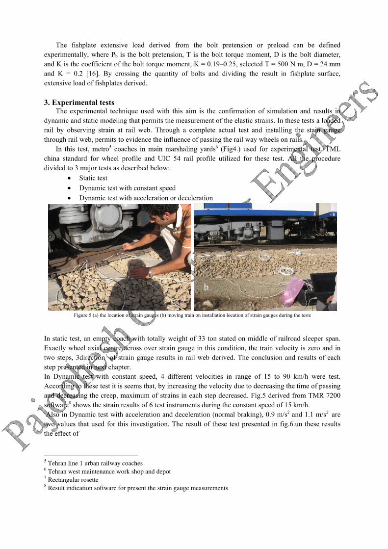
Figure 5 (a) the location of strain gauges (b) moving train on installation location of strain gauges during the tests
In static test, an empty coach with totally weight of 33 ton stated on middle of railroad sleeper span. Exactly wheel axial centre across over strain gauge in this condition, the train velocity is zero and in two steps, 3direction7 of strain gauge results in rail web derived. The conclusion and results of each step presented in next chapter. In Dynamic test with constant speed, 4 different velocities in range of 15 to 90 km/h were test. According to these test it is seems that, by increasing the velocity due to decreasing the time of passing and decreasing the creep, maximum of strains in each step decreased. Fig.5 derived from TMR 7200 software8 shows the strain results of 6 test instruments during the constant speed of 15 km/h. Also in Dynamic test with acceleration and deceleration (normal braking), 0.9 m/s2 and 1.1 m/s2 are two values that used for this investigation. The result of these test presented in fig.6.un these results the effect of
5 Tehran line 1 urban railway coaches 6 Tehran west maintenance work shop and depot 7 Rectangular rosette 8 Result indication software for present the strain gauge measurements
b
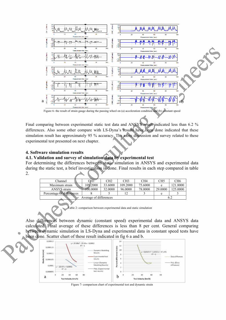
Figure 6- the result of strain gauge during the passing wheel on (a) acceleration condition and (b) constant speed
Final comparing between experimental static test data and ANSYS result indicated less than 6.2 % differences. Also some other compare with LS-Dyna’s results have been done indicated that these simulation result has approximately 95 % accuracy. The more discussion and survey related to these experimental test presented on next chapter.
4. Software simulation results 4.1. Validation and survey of simulation data by experimental test For determining the differences between static simulation in ANSYS and experimental data during the static test, a brief investigation is done. Final results in each step compared in table 2. Also differences between dynamic (constant speed) experimental data and ANSYS data calculated. Final average of these differences is less than 8 per cent. General comparing between dynamic simulation in LS-Dyna and experimental data in constant speed tests have been done. Scatter chart of these result indicated in fig 6 a and b.
Figure 7- comparison chart of experimental test and dynamic strain
CH6 CH5 CH4 CH3 CH2 CH1 Channel 121.8000 e 75.6000 109.2000 33.6000 109.2000 Maximum strain 125.0000 29.0000 78.0000 96.0000 32.0000 100.0000 ANSYS strain
3 e 3 12 5 8 Percentage of differences 6.2 Average of differences
Table 2: comparison between experimental data and static simulation
b a
ba
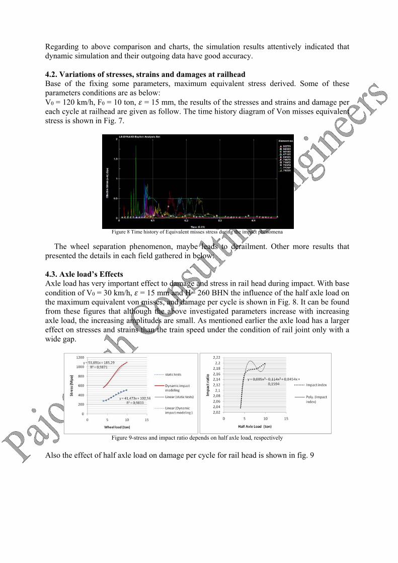
Regarding to above comparison and charts, the simulation results attentively indicated that dynamic simulation and their outgoing data have good accuracy. 4.2. Variations of stresses, strains and damages at railhead Base of the fixing some parameters, maximum equivalent stress derived. Some of these parameters conditions are as below: V0 = 120 km/h, F0 = 10 ton, = 15 mm, the results of the stresses and strains and damage per each cycle at railhead are given as follow. The time history diagram of Von misses equivalent stress is shown in Fig. 7.
Figure 8 Time history of Equivalent misses stress during the impact phenomena
The wheel separation phenomenon, maybe leads to derailment. Other more results that presented the details in each field gathered in below: 4.3. Axle load’s Effects Axle load has very important effect to damage and stress in rail head during impact. With base condition of V0 = 30 km/h, = 15 mm and H= 260 BHN the influence of the half axle load on the maximum equivalent von misses, and damage per cycle is shown in Fig. 8. It can be found from these figures that although the above investigated parameters increase with increasing axle load, the increasing amplitudes are small. As mentioned earlier the axle load has a larger effect on stresses and strains than the train speed under the condition of rail joint only with a wide gap.
Figure 9-stress and impact ratio depends on half axle load, respectively
Also the effect of half axle load on damage per cycle for rail head is shown in fig. 9
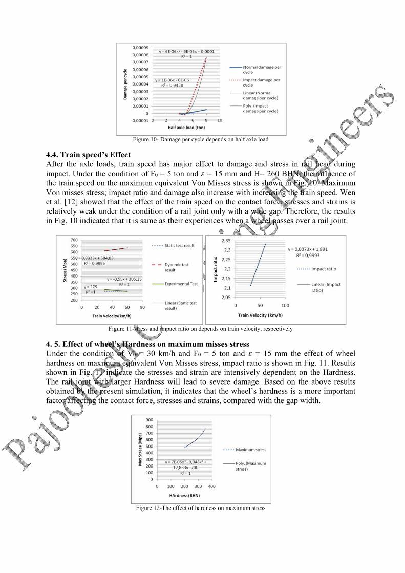
Figure 10- Damage per cycle depends on half axle load
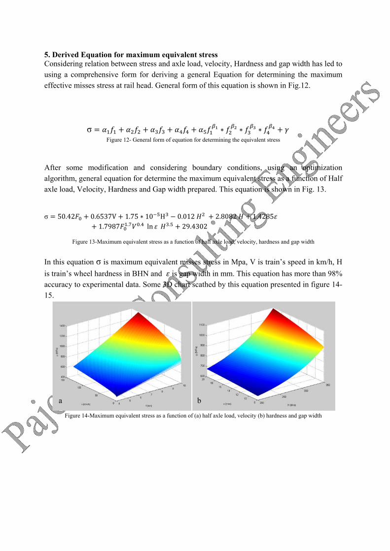
4.4. Train speed’s Effect After the axle loads, train speed has major effect to damage and stress in rail head during impact. Under the condition of F0 = 5 ton and = 15 mm and H= 260 BHN, the influence of the train speed on the maximum equivalent Von Misses stress is shown in Fig. 10. Maximum Von misses stress; impact ratio and damage also increase with increasing the train speed. Wen et al. [12] showed that the effect of the train speed on the contact force, stresses and strains is relatively weak under the condition of a rail joint only with a wide gap. Therefore, the results in Fig. 10 indicated that it is same as their experiences when a wheel passes over a rail joint.
Figure 11-stress and impact ratio on depends on train velocity, respectively
4. 5. Effect of wheel’s Hardness on maximum misses stress Under the condition of V0 = 30 km/h and F0 = 5 ton and = 15 mm the effect of wheel hardness on maximum equivalent Von Misses stress, impact ratio is shown in Fig. 11. Results shown in Fig. 11 indicate the stresses and strain are intensively dependent on the Hardness. The rail joint with larger Hardness will lead to severe damage. Based on the above results obtained by the present simulation, it indicates that the wheel’s hardness is a more important factor affecting the contact force, stresses and strains, compared with the gap width.
Figure 12-The effect of hardness on maximum stress
5. Derived Equation for maximum equivalent stress Considering relation between stress and axle load, velocity, Hardness and gap width has led to using a comprehensive form for deriving a general Equation for determining the maximum effective misses stress at rail head. General form of this equation is shown in Fig.12.
σ ∗ ∗ ∗ Figure 12- General form of equation for determining the equivalent stress
After some modification and considering boundary conditions, using an optimization algorithm, general equation for determine the maximum equivalent stress as a function of Half axle load, Velocity, Hardness and Gap width prepared. This equation is shown in Fig. 13.
σ 50.42 0.6537V 1.75 ∗ 10 H 0.012 2.8082 1.42851.7987 . . ln . 29.4302
Figure 13-Maximum equivalent stress as a function of half axle load, velocity, hardness and gap width
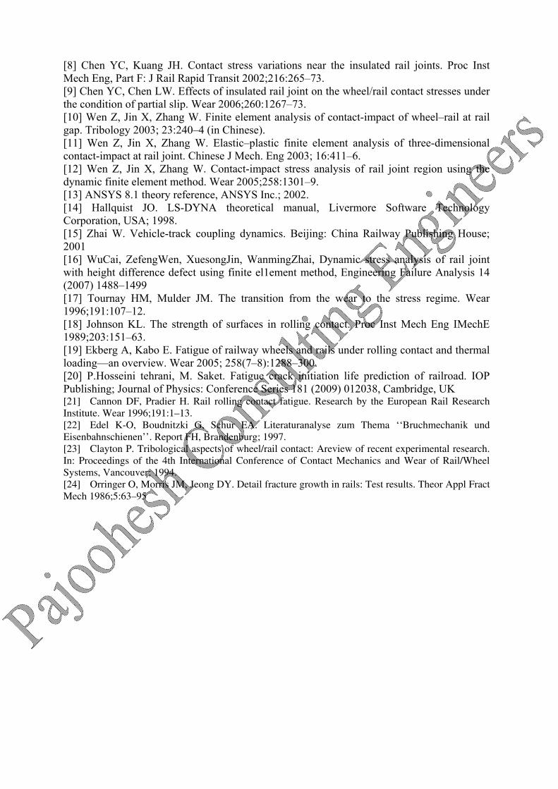
In this equation σ is maximum equivalent misses stress in Mpa, V is train’s speed in km/h, H is train’s wheel hardness in BHN and is gap width in mm. This equation has more than 98% accuracy to experimental data. Some 3D chart scathed by this equation presented in figure 14-15.
Figure 14-Maximum equivalent stress as a function of (a) half axle load, velocity (b) hardness and gap width
a b
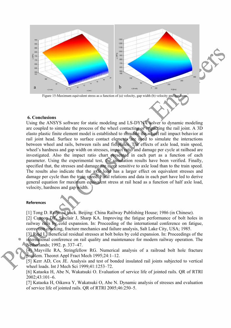
Figure 15-Maximum equivalent stress as a function of (a) velocity, gap width (b) velocity and hardness
6. Conclusions Using the ANSYS software for static modeling and LS-DYNA solver to dynamic modeling are coupled to simulate the process of the wheel contacting or impacting the rail joint. A 3D elasto plastic finite element model is established to simulate the wheel rail impact behavior at rail joint head. Surface to surface contact elements are used to simulate the interactions between wheel and rails, between rails and fishplates. The effects of axle load, train speed, wheel’s hardness and gap width on stresses, impact ratio and damage per cycle at railhead are investigated. Also the impact ratio chart presented in each part as a function of each parameter. Using the experimental test, the simulation results have been verified. Finally, specified that, the stresses and damage are more sensitive to axle load than to the train speed. The results also indicate that the axle load has a larger effect on equivalent stresses and damage per cycle than the train speed. Final relations and data in each part have led to derive general equation for maximum equivalent stress at rail head as a function of half axle load, velocity, hardness and gap width.
References
[1] Tong D. Railroad track. Beijing: China Railway Publishing House; 1986 (in Chinese). [2] Cannon DF, Sinclair J, Sharp KA. Improving the fatigue performance of bolt holes in railway rails by cold expansion. In: Proceeding of the international conference on fatigue, correction cracking, fracture mechanics and failure analysis, Salt Lake City, USA; 1985. [3] Reid L. Beneficial residual stresses at bolt boles by cold expansion. In: Proceedings of the international conference on rail quality and maintenance for modern railway operation. The Netherlands; 1992. p. 337–47. [4] Mayville RA, Stringfellow RG. Numerical analysis of a railroad bolt hole fracture problem. Theoret Appl Fract Mech 1995;24:1–12. [5] Kerr AD, Cox JE. Analysis and test of bonded insulated rail joints subjected to vertical wheel loads. Int J Mech Sci 1999;41:1253–72. [6] Kataoka H, Abe N, Wakatsuki O. Evaluation of service life of jointed rails. QR of RTRI 2002;43:101–6. [7] Kataoka H, Oikawa Y, Wakatsuki O, Abe N. Dynamic analysis of stresses and evaluation of service life of jointed rails. QR of RTRI 2005;46:250–5.
ba
[8] Chen YC, Kuang JH. Contact stress variations near the insulated rail joints. Proc Inst Mech Eng, Part F: J Rail Rapid Transit 2002;216:265–73. [9] Chen YC, Chen LW. Effects of insulated rail joint on the wheel/rail contact stresses under the condition of partial slip. Wear 2006;260:1267–73. [10] Wen Z, Jin X, Zhang W. Finite element analysis of contact-impact of wheel–rail at rail gap. Tribology 2003; 23:240–4 (in Chinese). [11] Wen Z, Jin X, Zhang W. Elastic–plastic finite element analysis of three-dimensional contact-impact at rail joint. Chinese J Mech. Eng 2003; 16:411–6. [12] Wen Z, Jin X, Zhang W. Contact-impact stress analysis of rail joint region using the dynamic finite element method. Wear 2005;258:1301–9. [13] ANSYS 8.1 theory reference, ANSYS Inc.; 2002. [14] Hallquist JO. LS-DYNA theoretical manual, Livermore Software Technology Corporation, USA; 1998. [15] Zhai W. Vehicle-track coupling dynamics. Beijing: China Railway Publishing House; 2001 [16] WuCai, ZefengWen, XuesongJin, WanmingZhai, Dynamic stress analysis of rail joint with height difference defect using finite el1ement method, Engineering Failure Analysis 14 (2007) 1488–1499 [17] Tournay HM, Mulder JM. The transition from the wear to the stress regime. Wear 1996;191:107–12. [18] Johnson KL. The strength of surfaces in rolling contact. Proc Inst Mech Eng IMechE 1989;203:151–63. [19] Ekberg A, Kabo E. Fatigue of railway wheels and rails under rolling contact and thermal loading—an overview. Wear 2005; 258(7–8):1288–300. [20] P.Hosseini tehrani, M. Saket. Fatigue crack initiation life prediction of railroad. IOP Publishing; Journal of Physics: Conference Series 181 (2009) 012038, Cambridge, UK [21] Cannon DF, Pradier H. Rail rolling contact fatigue. Research by the European Rail Research Institute. Wear 1996;191:1–13. [22] Edel K-O, Boudnitzki G, Schur EA. Literaturanalyse zum Thema ‘‘Bruchmechanik und Eisenbahnschienen’’. Report FH, Brandenburg; 1997. [23] Clayton P. Tribological aspects of wheel/rail contact: Areview of recent experimental research. In: Proceedings of the 4th International Conference of Contact Mechanics and Wear of Rail/Wheel Systems, Vancouver; 1994. [24] Orringer O, Morris JM, Jeong DY. Detail fracture growth in rails: Test results. Theor Appl Fract Mech 1986;5:63–95