the dhc 2000 torch - torchweldtorchweld.com/downloads/dhc_2000_torch_manual.pdf · introducing the...
TRANSCRIPT

Manufacturer ofDHC 2000 WELDING SYSTEM
(Formerly Dillion MK IV/Henrob 2000)
OPERATINGINSTRUCTIONS
THE DHC2000 TORCH
•


Please Note: Important safety instructions are located on thefollowing page. Maintenance Instructions are located on Page 20.
INDEX..........................................................................Page No.
INTRODUCTION ................................................Following pageSAFETY INSTRUCTIONS .................................Following pageWARRANTY INFORMATION ................................................... 1WELDING................................................................................. 2GAS PRESSURES................................................................... 2PURGING................................................................................. 3PRESSURE SETTING, METHOD 1 ........................................ 3PRESSURE SETTING, METHOD 2 ........................................3EXTINGUISHING FLAME ........................................................ 4FLAME CHARACTERISTICS................................................... 4FLAME SETTING..................................................................... 4TIP CLEANING......................................................................... 4TIP SELECTION....................................................................... 5WELDING POSITION............................................................... 6WELDING TECHNIQUE........................................................... 7BACKHAND WELDING............................................................ 8TEMPERATURE....................................................................... 9FLUXES.................................................................................... 9PREPARATION, CLEANING.................................................... 9CUTTING - OXYGEN & ACETYLENE ..................................... 9CUTTING THICK STEEL ......................................................... 9
ASSEMBLY................................................................... 10TRIGGER...................................................................... 11FLAME SETTING ......................................................... 11PROCEDURE ............................................................... 11TIP POSITION.............................................................. 12
CUTTING - SHEET STEEL.................................................... 13ASSEMBLY................................................................... 13TRIGGER ..................................................................... 14FLAME SETTING ......................................................... 14TIP POSITION.............................................................. 15
PROCEDURE......................................................................... 15CUTTING NON-FERROUS METAL....................................... 15ACETYLENE & AIR HEATING ATTACHMENT ...................... 15
ASSEMBLY................................................................... 16PROCEDURE............................................................... 16
MAINTENANCE INSTRUCTIONS .................................... 16-17FAULT FINDING..................................................................... 17PARTS LIST ........................................................................... 18
INTRODUCTIONThese instructions are intended for experienced operators and / or those working under theclose supervision of skilled welders. Operation and maintenance of welding and cuttingequipment should conform to the provisions of American National Standard Z49.1, “Safety inWelding and Cutting”. American Welding Society Manual C4.2-78, “Operatorʼs Manual ForOxy-Fuel Gas Cutting”, deserves careful study.
Reference PublicationsAWS C4.2-78 - “Operator Manual for Oxy-Fuel Gas Cutting” - American Welding Society, 550N.W. LeJeune Rd., Miami, FL 33126
ANSI Z49.1 - “Safety in Welding and Cutting” - American National Standards Institute, 1430Broadway, New York, NY 10018
Compressed Gas Association (CGA)1235 Jefferson Davis Highway, Arlington, VA 22202• Safety Bulletin SB.8 - “Use of Oxy-Fuel Gas Welding and Cutting Apparatus”• Pamphlet E-1 - “Standard Connections for Regulator Outlets”• CGA Standard V-1 - “Compressed Cylinder Valve Inlet and Outlet Connections”
SAFETY INSTRUCTIONSWarning: When using welding and cutting torches, basic safety precautions mustalways be followed to reduce the risk of fire and personal injury, including the following:1. Wear protective attire. Always wear welding goggles to protect eyes from sparks and light rays. Use
appropriate gloves and wear protective clothing. Watch for sparks in cuffs. Do not wear oily gloves.2. Handle gas cylinders with care. Chain or otherwise secure cylinders to a permanent fixture. Take care
when moving. To transport cylinders, remove regulators and replace with valve cap. Never use anycylinder in other than an upright position.
3. Use “good housekeeping” in the work area. Keep sparks and flame away from combustibles.Prepare your work area before welding or cutting.
4. Do not oil or grease equipment. The equipment does not require lubrication. Oil or grease is easilyignited and burns violently in the presence of oxygen.
5. “Crack” oxygen cylinder valve before installing regulator. Open valve slightly and then close. Thiswill clear valve of dust or dirt, which may be carried into the regulator and cause damage or accident.Do not discharge flow of gas at any person or flammable material.
6. Use check valves. Check valves must be fitted to the torch hand piece to prevent back flow of gasses.Test check valves for correct function frequently, at least every six months or in the event of a flashbackor backfire.
7. Be sure all connections are tight. Do not force connections. Never test for leaks with a flame. Use asoapy water solution and check for bubbles.
8. Purge oxygen and fuel gas passages separately before lighting torch. This will aid in preventingimproper mixes of gases.
9. Use recommended pressure settings. Improper pressures are wasteful. Extreme pressure build upin regulators is a warning they need repair.
10. Never use oxygen to blow off work or clothing. Oxygen supports combustion, spark can igniteoxygen-saturated clothing.
11. Purge system after use. When shutting down; close cylinder valves then bleed system by emptyingboth hoses independently. First, open torch oxygen “OX” needle valve, drain line until pressure is zero,then close oxygen needle valve. Repeat process with torch fuel “GAS” needle valve.
12. Do not work with damaged or leaking equipment. Use soapy water when checking for leaks. Donot use frayed or damaged hose. Never use torch as a hammer or to knock slag from work.
13. Handle equipment with care. Continued good service and your safety depend on it.14. Keep work area well ventilated. Flammable materials burn violently in an oxygen atmosphere.
Flames and glowing materials (smoking) must be avoided when using oxygen. See American NationalStandard Z49.1, paragraph 8.1.2.
15. When working with acetylene, never use at pressures over 15 PSIG (Pounds per Square Inch Gage).16. Do not force connectors and threads. The differences are intentional for the various gases.

Introducing theDHC 2000
TorchManufactured by Cobra Torches, Inc.
The DHC 2000 Torch has been developed over a period oftwenty years. It is manufactured to exacting specificationsto achieve the required characteristics.
To obtain optimum performance of the unit theseinstructions should be read and thoroughly understood.For those already experienced with similar typeequipment, some minor and simple changes to operatortechnique are required and these will be emphasizedthroughout these instructions.
COBRA: Lifetime WarrantyThe DHC 2000 Welding Cutting handpiece is guaranteedfor life to the original purchaser against any defect due tofaulty material or workmanship, excluding tips. Upon thediscretion of the manufacturer you will receive free ofcharge, a replacement unit or the free repair andreplacement of faulty parts. When returning a unit alloriginal standard equipment should also be returned.Cobra Torches, Inc. accepts no responsibility for defects,damage or faulty performances caused by misuse,careless handling or where repairs have been made orattempted by unauthorized persons. No other guarantees,written or verbal, are authorized to be made on the behalfof Cobra Torches, Inc. All other conditions and warrantieswhether expressed or implied are, to the extent permittedby law, hereby excluded.
Page 2
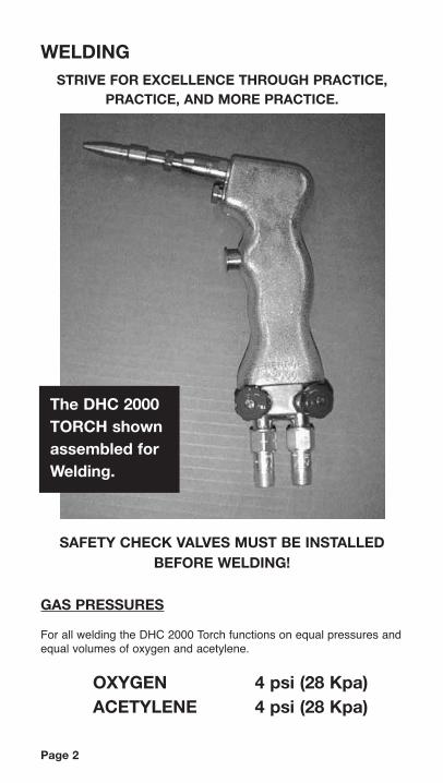
WELDING
GAS PRESSURES
For all welding the DHC 2000 Torch functions on equal pressures andequal volumes of oxygen and acetylene.
OXYGEN 4 psi (28 Kpa)ACETYLENE 4 psi (28 Kpa)
The DHC 2000TORCH shownassembled for Welding.
STRIVE FOR EXCELLENCE THROUGH PRACTICE,PRACTICE, AND MORE PRACTICE.
SAFETY CHECK VALVES MUST BE INSTALLEDBEFORE WELDING!
PURGINGAlways purge system before using. Read all steps and fully understand this procedureprior to doing it.
Warning: Purge only in a well ventilated area. Do not direct flow of gas towards anyperson or any flammable materials. Do not purge near open flames or any source ofignition.
1. With both valves on the torch body closed and the trigger button locked in the offposition, slowly open supply valve on the Oxygen cylinder, then adjust regulator to 4psi or until the oxygen gauge shows a reading.
2. Open the Oxygen (blue) torch valve and allow gas to flow about one second foreach ten feet of hose length. Close torch valve.
3. Slowly open supply valve on the Acetylene cylinder not more than one full turn, thenadjust regulator to 4 psi pressure.
4. Open the Acetylene (red) torch valve and allow gas to flow for about one second foreach ten feet of hose length. Close torch valve.
5. The torch is now purged.
PRESSURE SETTING
Method 1: Pressures are set at 4psi using gauges on regulators. This first method requires that you have pressure gauges fitted to your oxygen andacetylene cylinders that can reliably indicate as low as 4 psi. If your gauges are notcapable of establishing 4 P.S.I. use Method 2 to set up correct pressures.
Method 2: Setting Pressures using flame characteristics.This method is used if you do not have a pressure gauge fitted to your oxygen oracetelyne cylinder that can reliably indicate as low as 4 psi.
Read all steps and fully understand this procedure prior to doing it.
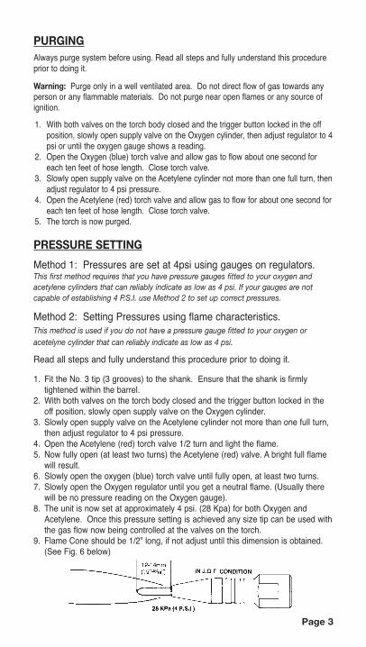
1. Fit the No. 3 tip (3 grooves) to the shank. Ensure that the shank is firmlytightened within the barrel.
2. With both valves on the torch body closed and the trigger button locked in theoff position, slowly open supply valve on the Oxygen cylinder.
3. Slowly open supply valve on the Acetylene cylinder not more than one full turn,then adjust regulator to 4 psi pressure.
4. Open the Acetylene (red) torch valve 1/2 turn and light the flame. 5. Now fully open (at least two turns) the Acetylene (red) valve. A bright full flame
will result.6. Slowly open the oxygen (blue) torch valve until fully open, at least two turns. 7. Slowly open the Oxygen regulator until you get a neutral flame. (Usually there
will be no pressure reading on the Oxygen gauge).8. The unit is now set at approximately 4 psi. (28 Kpa) for both Oxygen and
Acetylene. Once this pressure setting is achieved any size tip can be used withthe gas flow now being controlled at the valves on the torch.
9. Flame Cone should be 1/2” long, if not adjust until this dimension is obtained.(See Fig. 6 below)
Page 3
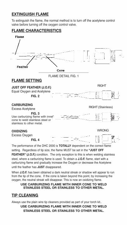
EXTINGUISH FLAMETo extinguish the flame, the normal method is to turn off the acetylene controlvalve before turning off the oxygen control valve.
FLAME CHARACTERISTICS
______________________________
FLAME DETAIL FIG. 1FLAME SETTING
JUST OFF FEATHER (J.O.F.)Equal Oxygen and Acetylene
FIG. 2
CARBURIZINGExcess Acetylene
FIG. 3
OXIDIZINGExcess Oxygen
FIG. 4
The performance of the DHC 2000 is TOTALLY dependent on the correct flamesetting. Regardless of tip size, the flame MUST be set in the “JUST OFFFEATHER” (J.O.F.) condition. The only exception to this is when welding stainlesssteel, where a carburizing flame is used. To obtain a J.O.F. flame, start with acarburizing flame and gradually increase the Oxygen or decrease the Acetyleneuntil the feather has JUST disappeared.
When J.O.F. has been obtained a dark neutral streak or shadow will appear to runfrom the tip of the cone. If the cone is taken beyond this point, by increasing theoxygen, the neutral streak will disappear. This is now an oxidizing flame.
USE CARBURIZING FLAME WITH INNER CONE TO WELDSTAINLESS STEEL OR STAINLESS TO OTHER METAL.
TIP CLEANING
Always use the plain wire tip cleaners provided as part of your torch kit..USE CARBURIZING FLAME WITH INNER CONE TO WELD
STAINLESS STEEL OR STAINLESS TO OTHER METAL.
Use carburizing flame with innercone to weld stainless steel orstainless to other metal.
RIGHT (Stainless)
RIGHT
WRONG

TIP SELECTIONA range of seven (7) tips are used to cover normal welding. An additionaleighth tip is used for cutting only. Do not use large brass tips for cutting thicksteels. Tip will over heat and fail.
APPROXIMATE GUIDE TO USE OF TIPS - FIG. 5
No. 00 Tip. (Identified by diamond knurl on No. 0 Tip. (Identified by smooth
barrel) barrel)* (optional tip)
Used for very fine work requiring the smallest For use in welding materials up to possible flame. Jewelry & 24-28 gage steel. 1.5mm (1/16”). 20-22 gage steel.
No. 0.5 Tip (Identified by single V groove on No. 1 Tip (Identified by single
square barrel)* (optional tip) groove on barrel)
*This tip is ideal for use in extensive welding For use in welding materials of of 20 ga.- 1/16 material. 1.5mm to 3.0mm (1/16” to 1/8”).
No. 2 Tip (identified by two square grooves No. 2.5 Tip (Identified by straight
knurl on barrel) on barrel)* (optional tip)
For use in welding materials of 3mm to 6mm *This tip is useful for heavy steel castand (1/8” to 1/4”) aluminum welding over 1/4”.
No. 3 Tip (Identified by three square Copper Cutting Tip (Identified by
grooves on copper barrel) color and diamond knurl on barrel)
*For use as a heating tip and set up purposes. For use only when cutting.Can also be used for heavy welding of cast, steel & aluminum.
Page 5
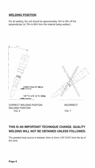
WELDING POSITION
For all welding, the unit should be approximately 10∞ to 20∞ off theperpendicular (or 70∞ to 80∞ from the material being welded.)
CORRECT WELDING POSITION INCORRECTWELDING POSITION
FIG. 6 FIG. 7
THIS IS AN IMPORTANT TECHNIQUE CHANGE. QUALITYWELDING WILL NOT BE OBTAINED UNLESS FOLLOWED.
The greatest heat source is between 3mm to 5mm (1/8”-3/16”) from the tip ofthe cone.
Page 6

WELDING TECHNIQUE
Due to the unique characteristics of the DHC 2000 flame, the cleaning ofmaterial to be welded and the use of flux is in many cases unnecessary.
A DIP IN - DIP OUT ACTION should be adopted.
DIP IN - DIP OUTFIG 8
FEED THE WELDING ROD UNDER AND BEHIND THE TIP OF THEFLAME CONE.
ROD POSITIONFIG. 9
IT IS IMPORTANT FOR THE FLAME TO BE IN FRONT OF THE WELDINGPROCESS as the molten metal will follow the flame (frequently referred to asa capillary action).
Page 7
Page 8
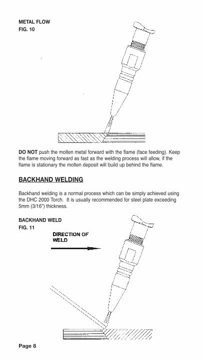
METAL FLOWFIG. 10
DO NOT push the molten metal forward with the flame (face feeding). Keepthe flame moving forward as fast as the welding process will allow, if theflame is stationary the molten deposit will build up behind the flame.
BACKHAND WELDING
Backhand welding is a normal process which can be simply achieved usingthe DHC 2000 Torch. It is usually recommended for steel plate exceeding5mm (3/16”) thickness.
BACKHAND WELDFIG. 11
TEMPERATURE
It should be noted an increase in gas pressure will NOT increase thetemperature rating of the flame, as the unit is designed to operate atmaximum efficiency at 4 psi (28 Kpa) If a greater volume of heat is required,increase the size of the flame or change to a larger tip.
FLUXES
In all instances where fluxes are used, minimal quantities are required. Thereare frequent occasions where no flux is required.
DO NOT use heavy coatings of flux.
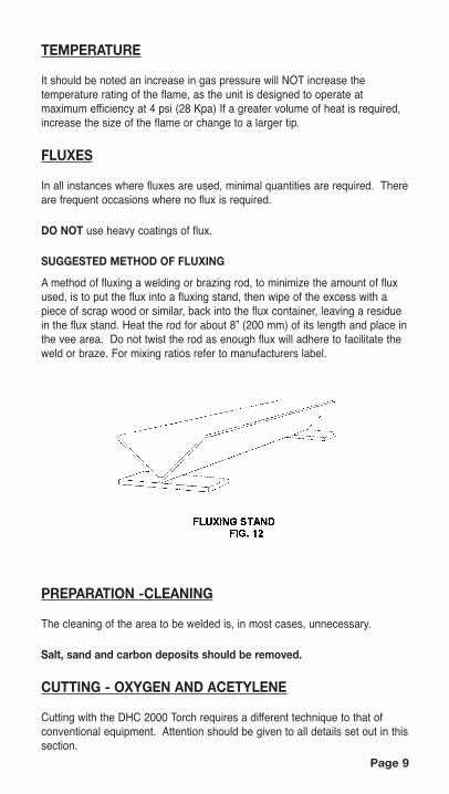
SUGGESTED METHOD OF FLUXING
A method of fluxing a welding or brazing rod, to minimize the amount of fluxused, is to put the flux into a fluxing stand, then wipe of the excess with apiece of scrap wood or similar, back into the flux container, leaving a residuein the flux stand. Heat the rod for about 8” (200 mm) of its length and place inthe vee area. Do not twist the rod as enough flux will adhere to facilitate theweld or braze. For mixing ratios refer to manufacturers label.
PREPARATION -CLEANING
The cleaning of the area to be welded is, in most cases, unnecessary.
Salt, sand and carbon deposits should be removed.
CUTTING - OXYGEN AND ACETYLENE
Cutting with the DHC 2000 Torch requires a different technique to that ofconventional equipment. Attention should be given to all details set out in thissection.
Page 9

Page 10
CUTTING - THICK STEEL
Fig 13. The DHC 2000 Torch shown assembled for cutting thick steel usingthe over cutter, complete with guide wheels and optional heat shield.
OXYGEN PRESSURES
The following is the suggested oxygen pressure for cutting steel of differentthickness. This suggestion can be adapted to suit individual operators.
1/4” 8-12 PSI 1/2” 14-16 PSI 3/4” 18-20 PSI 1” 22-25 PSI
ACETYLENE PRESSURE
For all cutting, acetylene is maintained at 4 psi (28 Kpa)
ASSEMBLY
Fit the cutting attachment to the DHC 2000 Torch as shown in Fig. 13. This isaccomplished by first removing the ʻBody Plugʼ from the cutting port, then(without a heating tip fitted) slide the cutting attachment onto the shank whileengaging the threaded fitting into the open cutting port. Tighten the threadedfitting sufficiently to prevent oxygen leakage as well as securing the cuttingattachment in place. The ʻCopper Cutting Tipʼ is fitted to the cuttingattachment and the Number 2 Tip is fitted to the shank for heating. The useof the guide wheels is optional; however it is recommended that the heatshield always be used when cutting.
Page 11
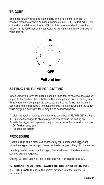
TRIGGER
The trigger button is located on the body of the torch and Is in the ʻONʼposition when the arrow is pointing upwards as in FIG. 13. To lock ʻOFFʼ, pullout and turn to left or right as in FIG. 13. It is recommended to have thetrigger in the ʻOFFʼ position when welding, but it must be in the ʻONʼ positionwhen cutting.
SETTING THE FLAME FOR CUTTING
When using your torch for cutting steel it is important to note that the oxygensupply to the torch is shared between the heating flame and the cutting flame.Thus when the cutting trigger is squeezed the heating flame may becomeacetylene rich (carburizing). The heating flame must be adjusted to be correctwhile oxygen is flowing to the cutting tip as described below.
1. Light the torch and establish a flame as described in FLAME DETAIL Fig.1.2. Squeeze the trigger to allow oxygen to flow through the cutting tip.3. With the trigger still depressed, adjust the flame to the desired size in Just
Off Feather condition4. Release the trigger
PROCEDURE
Heat the edge of the steel to a bright cherry red, depress the trigger andmove the oxygen delivery point over the heated edge - cutting will commence.
Beveling can be carried out by angling the handpiece in the direction thebeveled angle is required.
Cutting 1/8” steel use No. 1 tip to heat and No. 1 or copper tip to cut.
IMPORTANT - AT ALL TIMES WATCH THE OXYGEN DELIVERY POINT,NOT THE FLAME to ensure the correct distance from the material ismaintained.

TIP POSITION - CUTTING STEEL PLATE.FIG. 14
IMPORTANT: The oxygen delivery point (cutting tip) must be just out of the flame area.The flame size can vary for thickness of material being cut and operatortechnique
For any oxygen and acetylene cutting, whether the unit is used manually ora wheel guide is used, the unit is held with the oxygen delivery pointperpendicular (90 degrees) to the surface of the material being cut..
The oxygen delivery point should be maintained approximately 1/16”(1.5mm) from the surface to be cut.
Piercing holes is achieved using the normal method i.e. after bringing thesurface to a very bright red, raise the oxygen delivery point to approximately12mm (1/2”) before introducing the oxygen. Once the plate is penetrated,return to the normal height 1.5mm (1/16”) above work and proceed to cutthe hole.
For optimum cutting, the oxygen delivery point should follow immediatelybehind the heating point.
PULL CUT
Page 12
IMPORTANT(1) Use a No. 2 tip at alltimes. The No. 1 and No.3 tipshould not be used in thecutting process.
Page 13
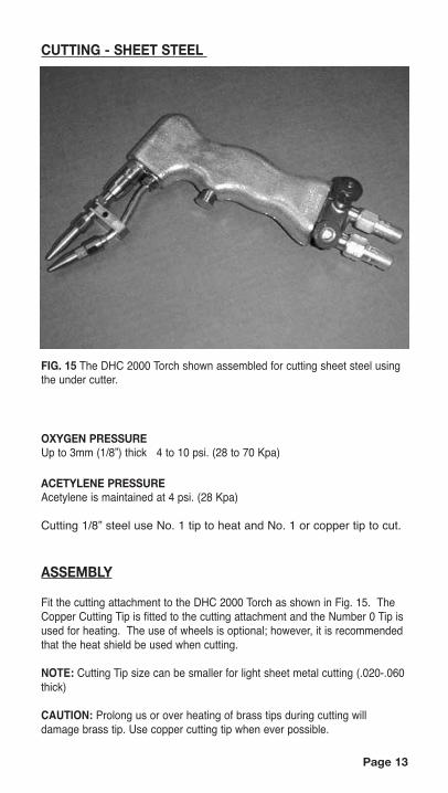
CUTTING - SHEET STEEL
FIG. 15 The DHC 2000 Torch shown assembled for cutting sheet steel usingthe under cutter.
OXYGEN PRESSUREUp to 3mm (1/8”) thick 4 to 10 psi. (28 to 70 Kpa)
ACETYLENE PRESSUREAcetylene is maintained at 4 psi. (28 Kpa)
Cutting 1/8” steel use No. 1 tip to heat and No. 1 or copper tip to cut.
ASSEMBLY
Fit the cutting attachment to the DHC 2000 Torch as shown in Fig. 15. TheCopper Cutting Tip is fitted to the cutting attachment and the Number 0 Tip isused for heating. The use of wheels is optional; however, it is recommendedthat the heat shield be used when cutting.
NOTE: Cutting Tip size can be smaller for light sheet metal cutting (.020-.060thick)
CAUTION: Prolong us or over heating of brass tips during cutting willdamage brass tip. Use copper cutting tip when ever possible.
Page 14
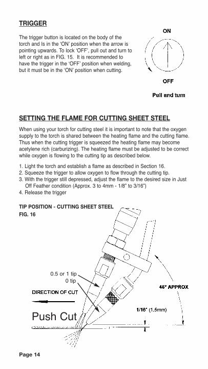
TRIGGER
The trigger button is located on the body of thetorch and Is in the ʻONʼ position when the arrow ispointing upwards. To lock ʻOFFʼ, pull out and turn toleft or right as in FIG. 15. It is recommended tohave the trigger in the ʻOFFʼ position when welding,but it must be in the ʻONʼ position when cutting.
SETTING THE FLAME FOR CUTTING SHEET STEEL
When using your torch for cutting steel it is important to note that the oxygensupply to the torch is shared between the heating flame and the cutting flame.Thus when the cutting trigger is squeezed the heating flame may becomeacetylene rich (carburizing). The heating flame must be adjusted to be correctwhile oxygen is flowing to the cutting tip as described below.
1. Light the torch and establish a flame as described in Section 16.2. Squeeze the trigger to allow oxygen to flow through the cutting tip.3. With the trigger still depressed, adjust the flame to the desired size in Just
Off Feather condition (Approx. 3 to 4mm - 1/8” to 3/16”)4. Release the trigger
TIP POSITION - CUTTING SHEET STEELFIG. 16
Push Cut
0.5 or 1 tip0 tip

Page 15
PROCEDURE
Heat the edge of the steel to a bright red, depress the trigger and move theoxygen delivery point over the heated edge - cutting will commence.
The flame size can vary for thickness of plate and operator technique.
Position the oxygen delivery point (cutting tip) should be at approximately45∞ from the surface of the material being cut. The operator may wish toslightly vary this angle to suit individual style.
IMPORTANT - AT ALL TIMES, WATCH THE OXYGEN DELIVERY POINT(NOT THE FLAME) and maintain the cutting tip no more than 1.5mm (1/16”)from the surface being cut. The cutting tip can be allowed to touch thesurface although this will slightly reduce tip life.
CUTTING (Controlled Melting) OF NON-FERROUSMETALS, CAST IRON AND LIGHT STEELDue to the confined heat zone and the non-oxidizing characteristics of theDHC 2000 torch flame, metals such as copper, brass, aluminum, cast ironand stainless steel can now be cut with a controlled melting process.
Assemble the unit as for welding.
A guide to the tip size to be used for specific material thickness can beassessed by using the tip that will normally weld the material.
Extend the cone to the maximum setting of the tip in use attaining the “just offfeather” condition. The point of the cone is used as the cutting media. Thehandpiece is tilted to right or left approximately 10-40∞ depending uponwhich side of the material is required to remain a clean edge.______________________________
ACETYLENE AND AIR HEATING ATTACHMENT(OPTIONAL FEATURE)
For soft soldering, tinning, silver soldering and general light heating withoutthe oxidizing of materials. The acetylene and air tip can be used in manyinstances. A soldering bit can be fitted for continued heating in soft soldering.
AIR-ACETYLENE HEATING ATTACHMENT FIG. 7

ASSEMBLYRemove tip and shank from barrel and insert acetylene and air piece to barrel asshown in Fig. 17. Tighten with wrench provided. Do not over tighten. Theacetylene setting is 4 psi (21-28 Kpa)
IMPORTANT OXYGEN MUST NEVER BE USED WITH THE AIR-ACETYLENE HEATING ATTACHMENT.
PROCEDUREWith the acetylene cylinder supply valve open a maximum of one turn andregulator set at 4 psi, open the acetylene valve on the torch body and light theflame at the end of the Air-Acetylene attachment. A cone condition will form in allinstances regardless of low settings at the torch body valve. Too high a flow orpressure will extinguish the flame when the handpiece control valve is fully open.
Should a burning occur at the holes of the air-acetylene attachment (this canoccur if the acetylene pressure is very low), an increase of acetylene willimmediately allow the cone to ʻfixʼ at the tip.
MAINTENANCE INSTRUCTIONS
Check Valves
Leak test Check Valves at least every six months, as follows:1. Shut off fuel gas supply and disconnect hose from check valve.2. Set oxygen regulator to 5 P.S.I., open all gas valves on torch or cutting
attachment.3. Plug tip and check for reverse flow to fuel gas check valve. Use soapy water
or immerse in water to check for leaks. Set pressure to zero after test.4. Reconnect fuel gas hose and disconnect oxygen hose.5. Repeat steps 2 and 3 using fuel gas regulator as pressure source.6. Reconnect hoses and purge system before use.
Regulator Test
A leak test of the regulators may be made as follows: (also see your regulatorinstruction manual)1. Shut off acetylene gas regulator by turning counter-clockwise until loose.2. Close fuel acetylene cylinder valve.3. Close acetylene (red) torch valve.
NOTE:• Watch acetylene cylinder pressure gage for several minutes. A pressure drop
indicates a leak in the inlet side. Tighten connection and recheck.• Also watch the delivery pressure gauge. A rise in pressure indicates a leak in
the regulator valve.• If leak cannot be stopped, DO NOT USE THE REGULATOR!• All gauges should read zero when the pressure is removed. If they do not,
the gauges may be damaged. If damaged, check system for cause ofdamaged gauges. Have the damage repaired by a qualified repairman orreplace the damaged gauges.
• Repeat procedure shown above for the oxygen regulator.
Page 16

CLEANING GAUGES
The gauge crystals are typically made of Lexan. Use only soapy water to clean,then wipe dry using soft cloths. Do not use solvents. ® General Electric Company
CHANGING CYLINDERS
A cylinder is depleted and is considered empty when it is unable to deliverfuel gas or oxygen to the torch tip at the set pressure.1. Close supply valve of depleted cylinder and bleed off all gas in depleted
line at torch. Close torch valve.2. Disconnect hose and regulator from depleted cylinder.3. Screw Valve Protection Cap onto cylinder, mark “EMPTY”, and remove.4. Follow the procedure under set-up instructions provided with the new
cylinder.5. Purge system (see below)
TORCHES AND CUTTING ATTACHMENTS
1. Periodically check for leaks using soapy water or by immersing in waterand checking for bubbles.
2. Tighten connections and packing nuts to stop leaks. Do not useexcessive force.
STORAGE
When not in use, store equipment in a clean and safe place.
FAULT FINDING
WELDINGPROBLEM POSSIBLE CAUSE REMEDY
Handpiece getting hot1.Incorrect pressure Pressure setting, page 32.Incorrect flame setting Flame setting, page 53.Reflected heat from job Use heat shield
Tip backfiring1.Tip too large for job Tip selection, page 62.Flame setting too low for tip size Tip selection, page 63.Flame cone forced into molten metal Welding technique, page 7
Unsatisfactory weld1. Incorrect flame setting Flame setting, page 52. Torch held at wrong angle Welding position, page 63. Rod not being used correctly Welding technique, page 7
Fluctuating flame1.Oxygen or acetylene regulator Have regulators serviced.
diaphragm faulty
Page 17

CUTTINGPROBLEM POSSIBLE CAUSE REMEDYWide cut, excessive Slag
1. Oxygen delivery point Position (Cutting), page 12too far from surface being cut
2. Insufficient pressure Pressures (Cutting), page 10
Burning off end of1. Tip inside flame area Flame setting (Cutting), page 11 (1)
oxygen delivery tip2. Tip allowed into molten Position (Cutting), page 12
metal
PARTS LISTW3006-106 Shank W3103-378 Tip Cleaner SetW3031-142 Body Plug W3105-369 Trigger Button AssemblyW3039-160 #0 Tip W3107-365 Oxygen ValveW3040-122 #1 Tip W3107-366 Acetylene ValveW3041-123 #2 Tip W3108-272 Cutting AttachmentW3041-159 Copper Cutting Tip W3111-273 Sheet Metal CutterW3042-124 #3 Tip W3110-143 BracketsW3045-132 Handle - Right W3102-148 Nut / BoltW3044-133 Handle - Left W3101-363 Guide RailsW3052-155 Wrench W3100-368 Torch BodyOPTIONAL ACCESSORIESW3038-176 #00 W3047-361 ShieldW3039-161 #0.5 Tip W3005-000 Curved ExtensionW3040-132 #1.5 Tip W3004-000 Straight ExtensionW3043-177 #2.5 Tip W3104-364 Air / Acetylene Tip
Page 18

We believe the two main ingredients forsuccessful welding are observation on thepart of the welder and the use of the DHC 2000 Torch.
TO BE RETAINED BY CUSTOMER
Serial No. Fill in the number stamped on valve body opposite control valves.
COBRA: LIfetime Limited WarrantyThe DHC 2000 Welding Cutting handpiece is guaranteed for thelifetime of the original purchaser against any defect due to facultymaterial or workmanship, excluding tips. Upon the discretion of themanufacturer you will receive free of charge, a replacement unit or thefree repair and replacement of faculty parts. In returning a unit alloriginal standard equipment should also be returned. Cobra Torch, Inc.accepts no responsibility for defects, damage or faculty performancescaused by misuse, careless handling or where repairs have been madeor attempted by unauthorized persons. No other guarantees, written orverbal, are authorized to be made on the behalf of Cobra Torch, Inc. Allother conditions and warranties whether expressed or implied are, t theextent permitted by law, hereby excluded.
Date of Purchase________________________
C
COBRA TORCHES, INC.219 South St.
Rochester, MI 48307Phone: 248-601-1664
Fax: 248-652-6544
SOLD BY:
MFD BY:
