the create clp 5130-1 log periodic antenna€¦ · the create clp 5130-1 log periodic antenna ......
TRANSCRIPT
CQ REVIEWS:
The Create CLP 5130-1 LogPeriodic Antenna
BY JOE LYNCH., N6CL
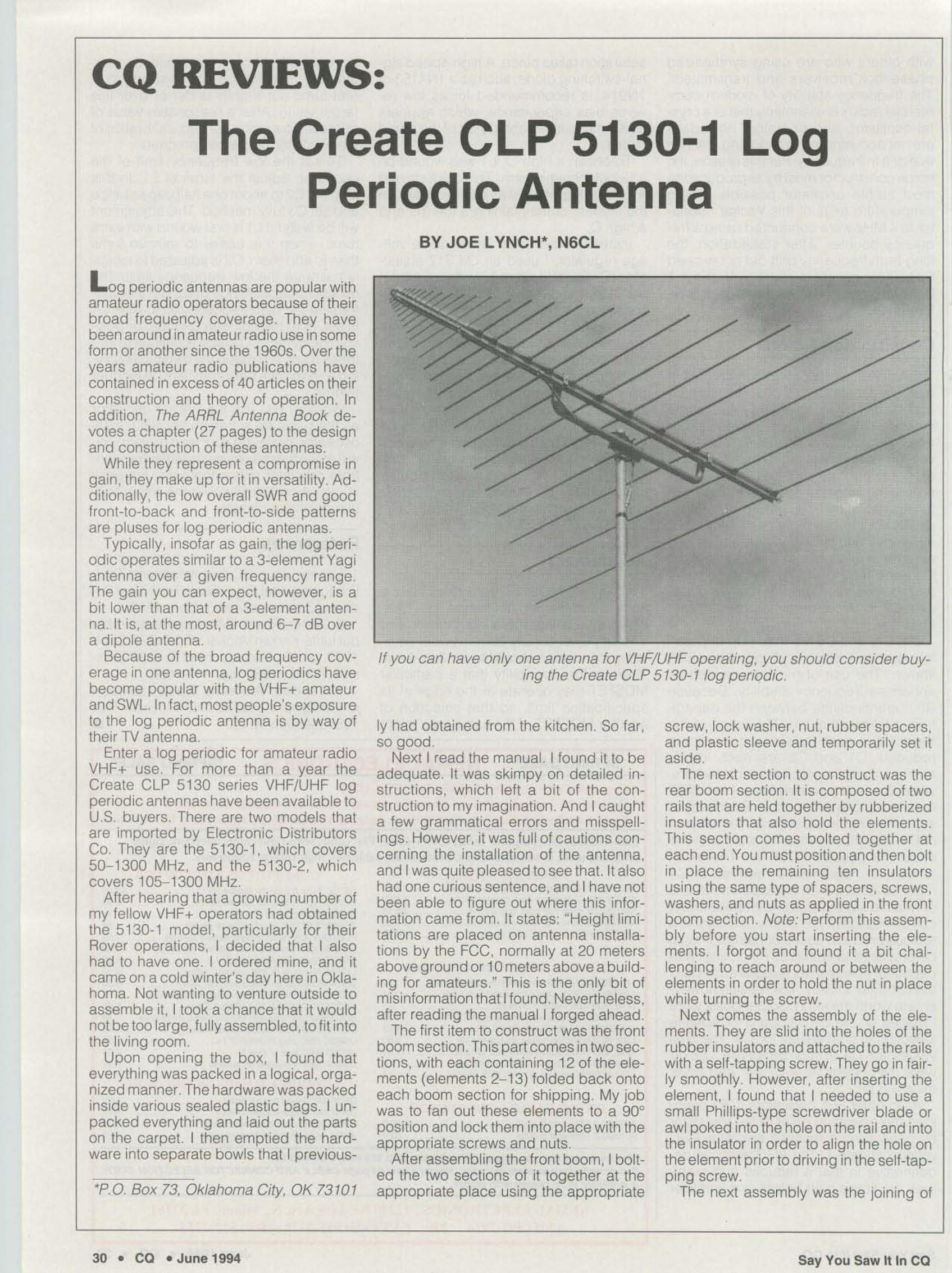
If you can have only one antenna for VHF/UHF operating, you should consider buying the Create CLP 5130-1 log periodic.
L og periodic antennas are popular withama teur radio operators because of theirbroad frequency coverage. They havebeen around inamateur radio use insomeform or another since the 19605. Over theyears amateur rad io publ ications havecontained in excess of 40 articles on theirconstruction and theory of operation. Inadd ition, The ARRL Antenna Book devotes a chapter (27 pages) to the designand construction of these antennas.
While they represent a compromise ingain , they make up for it in versatility. Additionally, the low overall SWR and goodtront-to-back and front-to-side patternsare pluses for log periodic antennas .
Typically, Insofar as gain, the log periodic operates similar to a 3-element Yagiantenna over a given frequency range,The gain you can expect, however, is abit lower than that of a a-element antenna. It is, at the most, around 6--7 dB overa dipole antenna.
Because of the broad frequency coverage in one antenna, log period ics havebecome popular with the VHF+ amateurand SWL. In fact. most people's exposureto the log periodic antenna is by way oftheir TV antenna,
Enter a log periodic for amateur radioVHF+ use, For more than a year theCreate CLP 5130 series VHF/UHF logperiod ic antennas have been available toU.S, buyers , There are two models thatare imported by Electronic DistributorsCo. They are the 5130-1, which covers50- 1300 MHz, and the 5130-2, wh ichcovers 105-1300 MHz.
After heari ng that a growing number ofmy fe llow VHF+ operators had obtainedthe 5130-1 mode l, particularly for the irRover operations, I decided that I alsohad to have one. I ordered mine, and itcame on a cold winter's day here in Oklahoma Not wanting to venture outside toassemble it. I took a chance that it wouldnot be too large, fully assembled, to fit intothe living room.
Upon opening the box, I found thateverything was packed in a log ical, organized manner. The hardware was packedinside various sealed plastic bags. I unpacked everything and laid out the partson the carpet. I then emptied the hard ware into separate bowls that! previous-
*P. D. Box 73, Oklahoma City, OK 73 101
30 • CO • June 1994
Iy had obtained from the kitchen. So far,so good.
Next I read the manual. I found it to beadequate. It was skimpy on detailed instructions, which left a bit of the construction to my imag ination. And I caughta few grammatical errors and misspel lings, However, it was full of cautions concerning the installation of the antenna,and I was quite p leased to see that. rtarsohad one curious sentence, and I have notbeen able to figure out where this information came from. It states: "Height limitations are p laced on antenna installations by the FCC, normally at 20 metersabove ground or 10 mete rs above a building for amateurs," This is the only b it ofmis informat ion that I found , Nevertheless,after read ing the manual I forged ahead.
The first item to construc t was the frontboom section.This part comes in two sections, with each containing 12 of the elements (elements 2- 13) fo lded back ontoeach boom section for shipping. My jobwas to fan out these elements to a 90°posit ion and lock them into place with theappropriate screws and nuts.
After assembling the front boom, I boiled the two sections of it together at theappropriate place using the appropriate
screw, lock washer, nut, rubber spacers,and plastic sleeve and temporarily set itaside,
The next section to construct was therear boom section. It is composed of tworails that are held together by rubberizedinsulators that also hold the elements.This section comes bo lted together ateach end ,Youmust position and then bollin place the remaini ng ten insulatorsusing the same type of spacers, screws,washers. and nuts as ap plied in the frontboom section. Note: Perform this assemb ly before you start inserting the elements, I forgot and found it a bit challenging to reach around or be tween theelements in order to hold the nut in p lacewhile turning the screw.
Next comes the assembly of the elements. They are slid into the holes of therubber insulators and attached to the railswith a self-tapping screw. They go in tairIy smoothly. However, after inserting theelement, I found that I needed to use asmall Phillips-type screwdriver blade orawl poked into the hole on the rail and intothe insulator in order to align the hole onthe element prior to driving in the self-tapping sc rew.
The next assemb ly was the joining of
Say You Saw It In CO
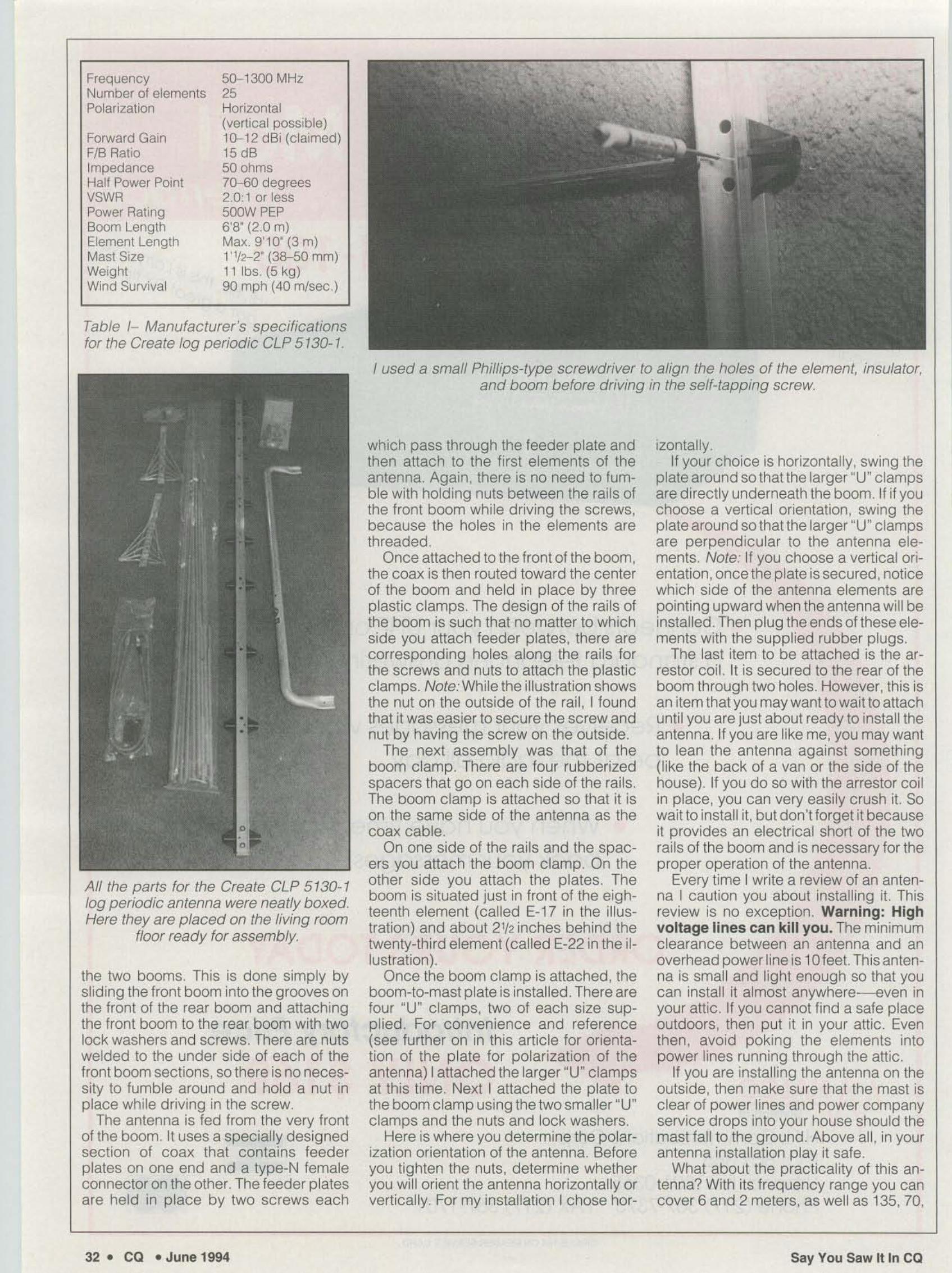
Table 1- Manufacturer's specificationsfor the Create log periodic CLP 5130-1 .
FrequencyNumber of elementsPolarization
Forward GainFIB RatioImpedanceHalf Power PointVSWRPower RatingBoom LengthElement LengthMast SizeWeightWind Survival
50-1300 MHz25Horizontal(vertical possible)10-12 dBi (claimed)15 dB50 ohms70-60 degrees2.0:1 or less500W PEP6'8" (2.0 m)Max . 9'10" (3 m)1' 112-2" (38-50 mm)11 lbs. (5 kg )90 mph (40 mlsec.)
I used a small Phillips-type screwdriver to align the holes of the element, insulator,and boom before driving in the self-tapping screw.
All the parts for the Create CLP 5 130-1log periodic antenna were neatly boxed,Here they are placed on the living room
floor ready far assembly.
the two booms. This is done simply byslid ing the lront boom into the grooves onthe front 01 the rear boom and attach ingthe front boom to the rear boom wi th twolock washers and screws. There are nutswelded to the under side of each 01 thefront boom sections, so there is no necessity to fumble around and hold a nut inplace while driving in the screw,
The antenna is fed from the very frontof the boom. It uses a specially designedsection of coax that contains feederplates on one end and a type-N lemaleconnector on the other. The feeder p latesare held in p lace by two screws each
32 • CO • June 1994
wh ich pass through the feeder p late andthen attach to the first elements of theantenna. Again, there is no need to fumble with holding nuts between the rails 01the front boom whi le d riving the screws,because the holes in the elements arethreaded.
Once attached to the lrontol the boom,the coax is then routed toward the center01 the boom and held in place by threeplastic clamps. The design of the rails ofthe boom is such that no matter to whic hside you attach feeder plates, there arecorresponding holes along the rails lorthe screws and nuts to attach the plasticclamps. Nate: While the illustration showsthe nut on the outside 01 the rail, I foundthat it was easier to secure the screw andnut by havi ng the screw on the outside.
The nex t assembly was that 01 theboom clamp. There are four rubber izedspacers that go on each side of the rails,The boom c lamp is attached so that it ison the same side 01 the antenna as thecoax cab le,
On one side of the rails and the spacers you attach the boom clamp. On theother side you attach the plates , Theboom is situated just in front of the eighteenth element (called E·17 in the illustration) and about 21f2inches behind thetwenty-th ird element (called E-22 in the illustration) .
Once the boom clamp is attached, theboom-to-mast plate is installed . There arefour HU~ clamps, two 01 each size supplied. For convenience and reference(see further on in th is article for orientat ion 01 the plate for polarization 01 theantenna) I attached the larger "U" cl ampsat this t ime. Next I attached the p late tothe boom c lamp using the two smaller "U"clamps and the nuts and loc k washers.
Here is where you determine the polarization orientation of the antenna. Beforeyou tighten the nuts, determine whetheryou will orient the antenna horizontally orvertically , For my instal lat ion I c hose her-
lzontany.If your choice is horizontally, swing the
plate around so that the larger " U~ clampsare directly underneath the boom. If if youchoose a vertical or ientation, swing theplate around so that the larger "U" clampsare perpend icular to the antenna elements. Note: II you choose a vertical orientation ,once the p late is secured, noticewhich side 01 the antenna elements arepointing upward when the antenna will beinstalled . Then plug the ends 01 these elements with the supplied rubber plugs .
The last item to be attached is the arrestor coil. It is secu red to the rear 01 theboom through two holes. However, this isan item that you may want to wait to attachuntil you are just about ready to install theantenna, If you are like me, you may wantto lean the antenna against something(like the back 01 a van or the side of thehouse) , If you do so with the arrestor coilin plac e, you can very easily c rush it. Sowait to install it, but don't lorget it becauseit provides an electrical short of the tworails 01 the boom and is necessary for theproper operation 01 the antenna.
Every time I write a review al an antenna I caution you about installing it. Thisreview is no exception. Warning: Highvo ltage lines can kill you , The minimumclearance between an antenna and anoverhead power line is t u teet. Thisanlenna is small and light enough so that youcan install it almost anywhere----even inyour att ic . II you cannot lind a sale placeoutdoors, then put it in your attic. Eventhen , avoid poking the elements intopower lines running through the allic.
II you are installing the antenna on theouts ide , then make sure that the mast isclear of power lines and power companyservice drops into your house should themast fa ll to the g round. Above all , in yourantenna installation play it safe .
What about the practicality 01 this antenna? With its frequency range you cancover 6 and 2 meters, as well as 135, 70,
Say You Saw It In CO
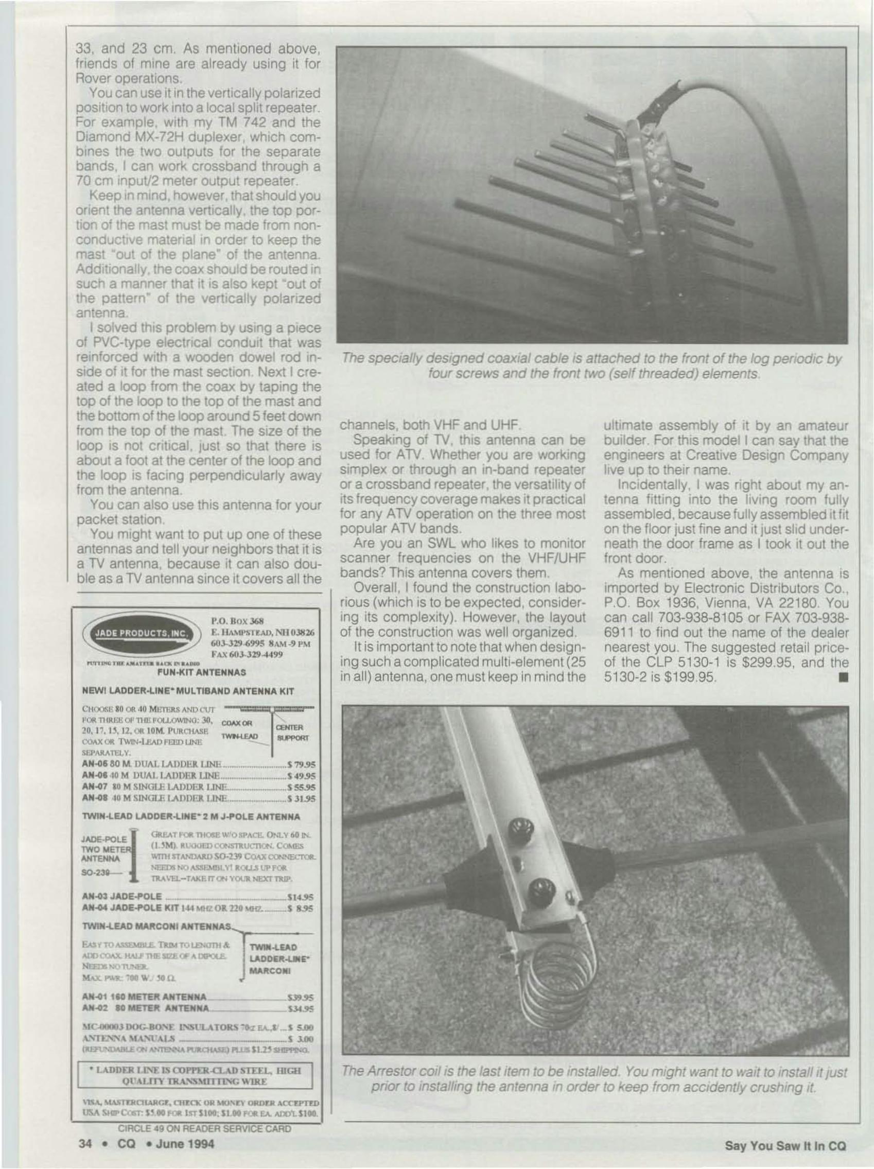
The specially designed coaxial cable is attached to the front of the log periodic byfour screws and the front /"NO (self threaded) elements,
ultimate assembly of it by an amateurbuilder. For this model I can say that theengineers at Creative Design Companylive up to their name.
Incidentally, I was right about my antenna fitting into the living room fullyassembled, because fully assembled it fiton the floor just fine and it just slid underneath the door frame as I took it out thefront door.
As mentioned above, the antenna isimported by Electronic Distributors Co.,P.O. Box 1936, Vienna, VA 22180. Youcan call 703-938-8105 or FAX 703·93869 11 to find out the name of the dealernearest you. The suggested retail priceof the CLP 5130-1 is $299,95, and the5130·2 is $199,95. •
channels, bath VHF and UHF.Speaking of TV, this antenna can be
used for ATV. Whether you are workingsimplex or through an in-band repeateror a crossband repeater. the versatility ofits frequency coverage makes it practicalfor any ATV operation on the three mostpopular ATV bands,
Are you an SWL who likes to monitorscanner frequenc ies on the VHF/UHFbands? This antenna covers Ihem.
Overall, I found the construc tion laborious (which is to be expected , considering its complexity), However, the layoutof the construction was well organized.
It is important to note that when designing such acomplicated mult i-element (25in all) antenna , one must keep in mind the~UN.j(1T ANTENNAS
NEWlLADDEIIl-lINE-MULTlSAND ANTENNA KIT
33, and 23 em. As mentioned above,friends of mine are already using it forRover operations.
You can use it In the vertically polarizedposi tion to work Into a local split repeater.For example, with my TM 742 and theDiamond MX-72H duplexer. which combines the two outputs for the separatebands. I can work crossband through a70 cm mput/2 meter output repeater.
Keep in mind. however, Ihat should youorient the antenna vertically, the top portion of the mast must be made from nonconductive material in order to keep themast "out of the plane- of the antenna,Additionally. the coax should be routed insuch a manner that it is also kept "out ofthe pattern" of the vertically polarizedantenna,
I solved this problem by using a pieceof PVC-type electrical conduit that wasreinforced with a wooden dowel rod inside of it for the mast section. Next 1created a loop from the coax by taping thetop of the loop to the top of the mast andthe bottom of the loop around 5 feet downfrom the top of the mast. The size of theloop is not critical. just so that there isabout a foot at the center of the loop andthe loop is facing perpendicularly awayfrom the antenna,
You can also use this antenna for yourpacket station.
You might want to put up one of theseantennas and tell your neighbors that it isa TV antenna, because it can also double as a TV antenna since it covers all the
" 0llOOOJ IlOG--ao" .: L"'St U TOIl-S -ta EA.." _ S s.oo"-'"TI ~""-";" " ""'T4l.l> S l.OO(~<JN .....-.-.. _otAIII,l Pl.lA ' 1.2~ liE I : m.
AN~ JAOE-POLE ..__ 514_'5AN-t04 JADIi!.-P()LE KIT 144 IoG1Z OJ. m I.lKZ. _ S 1.'5
TWIN-lEAD MAJl!eONI ANTENMA''--,- _
TWIIl....UD.....DOilll~~MAItCOIII
F-ASTTQ·...... F ~TQU>«JTIta.
AlVCQI\X IWJ' THE II1.£Of A DIJ'Ol£._W~
MAx- .............. "u"".(11110 MEn-it UTEN"""".(12 10 MEn-it ""TENNA
C>l(xliS~ 10 01\ 1(1 MliTER.H .ND C'UT
,OIl TIIRE., Of TIlE fOlJ..OWlNO' 30. <X\oO,>: OIl10. 17, I~. Il. Olt 10M. P"Ill Q IASH ~ ~
C<:JoO.X 01\ TWIN·I.e..v fl W l.lN'Ii ---. --
Sl~AIlAT1-l.V.
AN .(II 50 M, DUAl. tADDU UNE _ _..s~.'J5AN~ ,10 M DUAL t.AlJ[llik UNE _..s 49.~
AN.(I7 1(1 M SlNGl.1'. lAIlIJ l;J. I1NL _.__._ S M.'J5AN~ MI MStNOl.f. I.All ll liJ. IJNIo:.•.._'"~ .._._ s J I.~
TWIN....EAD LADDEIt-lINE- 2 M J-POLE ANTENNA
JADE-POL.£i {lIY!AT fOIl THOIEWO..AC1'- C/Nl.v 60 11<.TWO lllETE ( I.'M~ ~liO<Jfl)CQM'TIl~. C<lt.IESNITENM wmlfr...."4lAAD!iO-!~co.u~
SO-2'_ Nf.lnlNO~Y! ~QU.!UPfOllTlV<\U-TAAl! 11'(1''' yOlJR NEXT TlUP.
• LAll llfJl I.I:''J: IS (Dm:R-o'AD SUU.. IUGHQt'Aun T1U.'lI~mn"iGWIRE
The Arrestor coil is the last Item to be Installed. You might want to wait to install it justprior to installing the antenna in order to keep from accidently crushing it.
'1M, ""IIJllnu.Jl()'. n,,", .... ..."..... OIQlU MTU'ITl)
USA lit.- CC51"c 5~.• fOIl I'IT Sl it: ,I." fOR EA. AJXtI. st.CIRCLE .!J ON READER SERVICE CARD
34 • CO • June 1994 Say You Saw It In CO