the cost effective use of fibre reinforced composites offshore
TRANSCRIPT
HSE Health & Safety
Executive
The cost effective use of fibrereinforced composites offshore
Prepared by the University of Newcastle Upon Tyne
for the Health and Safety Executive 2003
RESEARCH REPORT 039
HSE Health & Safety
Executive
The cost effective use of fibre reinforced composites offshore
Professor A G Gibson Centre for Composite Materials Engineering
University of Newcastle Upon Tyne Newcastle upon Tyne
NE1 7RU United Kingdom
The results of a major research programme into the cost effective use of fibre reinforced composites offshore, undertaken as a Joint Industry Project by a consortium of universities and contractors are presented in this report.
The report includes a detailed (54 page) summary of current offshore composite applications, followed by a review of the 43 projects conducted during the programme which spanned 13 years and four phases of research and considered the following performance issues – fire, blast/impact, environmental durability, elevated temperatures, jointing, long term behaviour, non-destructive inspection and structural design. These are related to the use of pipes, panels, secondary structures e.g. gratings, walkways etc. and top-side structures.
The report is intended for use as an information source for engineers involved in the use of composites offshore. The most significant advances have been in the areas of pipework and fluid handling, driven by their light weight and corrosion resistance compared to metals. Until recently, interest focussed on the use of glass fibre-based composites and on the topsides of offshore platforms. However, the prospect of deepwater production is generating a new impetus for high performance composites for demanding subsea applications. The probable scale of some new subsea developments, such as rigid risers and tethers is likely to result in greatly increased demand for carbon based composites as well as for the manufacturing facilities to process them. Composite down-hole tubing is also beginning to find applications subsea and in well intervention.
The original barriers to the use of composites offshore were regulatory requirements, lack of design information and the fragmented structure of the composites industry. The project has made significant progress in their removal, as well as generating increased awareness of the major economic, safety and environmental benefits that a wider use of composite materials can bring. The Composites Offshore programme provided valuable underpinning information for a number of applications, including glass reinforced plastic (GRP) piping, offshore structures, repair systems and composite fire protection of the oil and gas industry.
This report and the work it describes were funded in part by the Health and Safety Executive (HSE). Its contents, including any opinions and/or conclusions expressed, are those of the authors alone and do not necessarily reflect HSE policy.
HSE BOOKS

© Crown copyright 2003
First published 2003
ISBN 0 7176 2591 5
All rights reserved. No part of this publication may bereproduced, stored in a retrieval system, or transmitted inany form or by any means (electronic, mechanical,photocopying, recording or otherwise) without the priorwritten permission of the copyright owner.
Applications for reproduction should be made in writing to: Licensing Division, Her Majesty's Stationery Office, St Clements House, 2-16 Colegate, Norwich NR3 1BQ or by e-mail to [email protected]
ii
CONTENTS
1. INTRODUCTION 1
2. SUMMARY OF APPLICATIONS 3
3. PIPES, TANKS AND VESSELS 7
3.1 Composite Pipework 7
3.1.1 Joining techniques 83.1.2 Steel strip laminate (SSL) pipe 103.1.3 Mechanical behaviour and failure modes 103.1.4 Applications 11
3.2 Tanks and Vessels 14
3.3 Flexible Thermosetting Tube 15
3.4 Reinforced Thermoplastic Pipe (RTP) 16
3.5 Lined Pipe 17
3.6 Rigid Risers 18
3.7 Flexible Risers 19
3.8 High Pressure Accumulator Bottles 20
3.9 Repair of metallic tubulars 21
4. STRUCTURAL APPLICATIONS 25
4.1 Blast and Fire Protection 25
4.2 Gratings and Stairways 27
4.3 Tethers and Tendons 27
5. MAJOR LOAD-BEARING STRUCTURAL USEOF COMPOSITES OFFFSHORE 29
5.1 Designers and Fabricators 31
5.2 Composites Industry Infrastructure 32
5.3 Scale-up of Fabrication Processes 32
6. RELEVANT PROPERTIES OF COMPOSITES 33
6.1 Environmental and Fatigue Behaviour 33
6.2 Fire Performance 35
6.2.1 Fire Reaction 36
6.2.2 Fire Resistance 39
6.2.3 Jet Fires Tests 39
iii

7. CONCLUSIONS 39
8. REFERENCES 43
iv
1. INTRODUCTION
This report reviews areas where composites are finding application in the oil and gas industry, onshore and offshore. The most significant advances have been made in the areas of pipework and fluid handling, driven by light weight and corrosion resistance compared to metals. Modest, but significant progress has also been made in structural applications. Lessons are being learned from successful applications with the result that operators, design houses and contractors are now beginning to take a serious interest in their wider use. Expansion is therefore expected to continue into all sectors of the oil and gas industry. Research results and new developments have been summarized in a number of references (ARP, 2000; ‘Composite Materials for Offshore Operations: Proceedings of the First International Workshop’, 1993; Croquette, 1994; Gibson, 1993, 2000, 2001; Institut Français du Pétrole, 1994; Salama, 1995 and Wang et al. (1999, 2000)).
Until recently, interest has focused on the use of glass fibre-based composites in onshore fluid transport and on the topsides of offshore platforms. However, the prospect of deepwater production is generating a new impetus for high performance composites for demanding sub sea applications. The probable scale of some new sub sea developments, such as rigid risers and tethers (see Sections 3.6 and 4.3) is likely to result in greatly increased demand for carbon based-based composites as well as for the manufacturing facilities to process them. Composite down-hole tubing is also beginning to find applications sub sea and in well intervention (Section 3.3).
In many cases the purchase cost of composite components exceeds that of their metallic counterparts. However, because of their relative ease of handling the installed cost, especially of pipe systems, is often lower than that of conventional steels. The cost advantages are even greater when composites replace expensive corrosion-resistant metals such as copper-nickel alloys, duplex or super duplex stainless steel or even titanium. Their corrosion resistance also improves reliability and leads to lower through-life costs.
As well as expected benefits, a number of barriers to the use of composites offshore were identified in the 1980’s. These were:
1. Regulatory requirements, especially on combustibility 2. Lack of relevant performance information, especially in hostile offshore
environments (including erosion, fatigue, wear and impact abuse, as well as fluid environments).
3. Lack of efficient design procedures and working standards, combined with unfamiliarity on the part of designers
4. The fragmented structure of the composites industry, and 5. Difficulty of scaling up fabrication processes to make very large composite
structures
The majority of research undertaken on offshore composites in the last two decades has been aimed at the removal of barriers 1-3, and much has been achieved, especially in the regulatory area where ‘prescriptive’ requirements have been largely replaced by ‘performance-based’ or ‘goal-setting’ones. Some remaining problems associated with infrastructure and process technologies will be discussed in Section 5.2.
1

2
2 SUMMARY OF APPLICATIONS
The most successful offshore applications for composites have been in pipework for aqueous liquids. Performance-based guidelines for the design of glass fibre reinforced epoxy (GRE) pipes have significantly accelerated these applications. These were initiated by UKOOA (United Kingdom Offshore Operators Association (1994) and has recently resulted a draft ISO standard (ISO 2000).
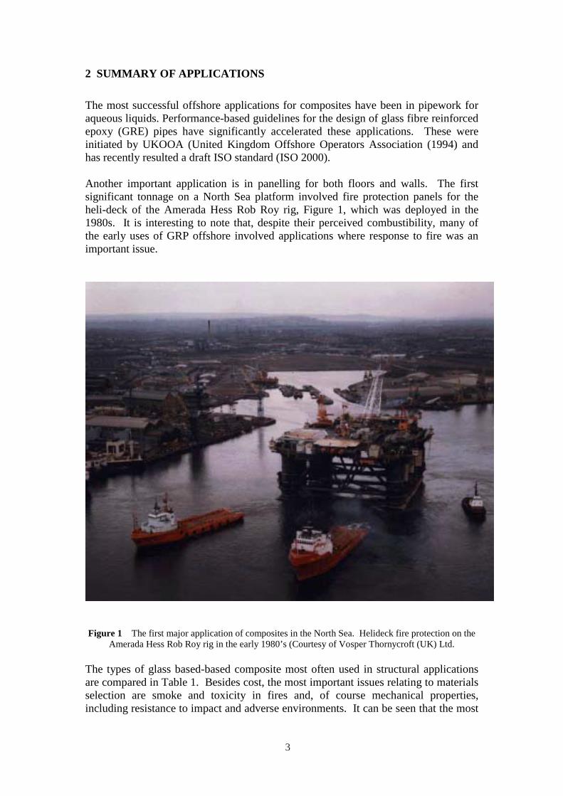
Another important application is in panelling for both floors and walls. The first significant tonnage on a North Sea platform involved fire protection panels for the heli-deck of the Amerada Hess Rob Roy rig, Figure 1, which was deployed in the 1980s. It is interesting to note that, despite their perceived combustibility, many of the early uses of GRP offshore involved applications where response to fire was an important issue.
Figure 1 The first major application of composites in the North Sea. Helideck fire protection on the Amerada Hess Rob Roy rig in the early 1980’s (Courtesy of Vosper Thornycroft (UK) Ltd.
The types of glass based-based composite most often used in structural applications are compared in Table 1. Besides cost, the most important issues relating to materials selection are smoke and toxicity in fires and, of course mechanical properties, including resistance to impact and adverse environments. It can be seen that the most
3
important structural materials, epoxy, vinyl ester and polyester, would probably be prevented from use in areas where smoke and toxicity would be a problem (Gibson, 2001). The most favourable systems from the viewpoint of toxicity are those based on phenolic resins. Modified acrylic resins, such as Modar, may also be used in certain toxicity-sensitive areas, but this resin type has yet to be widely used offshore.
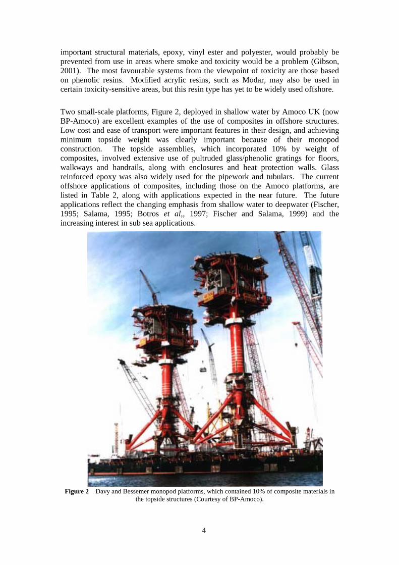
Two small-scale platforms, Figure 2, deployed in shallow water by Amoco UK (now BP-Amoco) are excellent examples of the use of composites in offshore structures. Low cost and ease of transport were important features in their design, and achieving minimum topside weight was clearly important because of their monopod construction. The topside assemblies, which incorporated 10% by weight of composites, involved extensive use of pultruded glass/phenolic gratings for floors, walkways and handrails, along with enclosures and heat protection walls. Glass reinforced epoxy was also widely used for the pipework and tubulars. The current offshore applications of composites, including those on the Amoco platforms, are listed in Table 2, along with applications expected in the near future. The future applications reflect the changing emphasis from shallow water to deepwater (Fischer, 1995; Salama, 1995; Botros et al,, 1997; Fischer and Salama, 1999) and the increasing interest in sub sea applications.
Figure 2 Davy and Bessemer monopod platforms, which contained 10% of composite materials in the topside structures (Courtesy of BP-Amoco).
4

Table 1 Candidate resin systems for use in offshore composites
Resin Mechanical integrity
Low smoke and
toxicity in fire
Cost
Polyester ***** * ***
Vinyl ester ******* * ******
Epoxy ********* * *********
Phenolic ***** **** ****
Mod. Acrylic **** ******* ****
Table 2
Recent applications of composites offshore
Fire protection Walkways and Lifeboats flooring
Blast protection Handrails Buoys and floats Corrosion protection Sub sea anti-trawl ESDV protection
structures Partition walls Casings Boxes, housings
and shelters Aqueous pipe J-tubes Loading gantry
systems Tanks and vessels Caissons Pipe refurbishment Firewater systems Cable trays and Riser protection
ladders Pipe liners Accumulator bottles Bend restrictors
Separator internals Well intervention Subsea instrument housings
Future applications
Rigid risers Coilable tubing Flexible risers Tendons Primary structure Separators
5

6
3. PIPES, TANKS AND VESSELS This section will discuss significant areas where composites are being employed for fluid transport and storage. The key products are:
• Filament wound thermosetting Pipework • Steel strip laminate (SSL) pipe • Fibreglass tanks and vessels • Thermosetting coil tube • Reinforced thermoplastic pipework (RTP) • Lined pipe • Rigid risers, and • High pressure flexible tubing
3.1 Composite Pipework
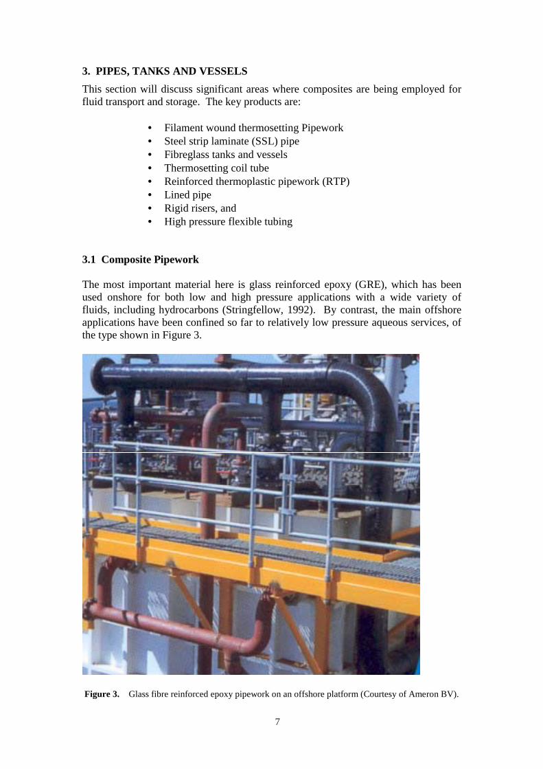
The most important material here is glass reinforced epoxy (GRE), which has been used onshore for both low and high pressure applications with a wide variety of fluids, including hydrocarbons (Stringfellow, 1992). By contrast, the main offshore applications have been confined so far to relatively low pressure aqueous services, of the type shown in Figure 3.
Figure 3. Glass fibre reinforced epoxy pipework on an offshore platform (Courtesy of Ameron BV).
7
The chemical resistance of GRE and the maximum use temperature in a particular fluid depends on the type of resin and hardener used. GRE tubes are largely immune to the effects of hydrogen sulphide and carbon dioxide. The most damaging chemical component is often water, rather than oil, although some highly aromatic species such as toluene and xylene can be damaging. General guidance on suitability for use in particular fluids is given by Stringfellow (1992) and by individual pipe manufacturers. Standards for the use of composite piping, such as ISO/DIS 14692 (2000), and qualification procedures, such as ASTM 2992 and ISO 109281 (1997) are facilitating the wider use of these products.
Although GRE pipe provides the best all-round chemical resistance a number of other resin types may also be used. These include:
• Isophthalic polyester, for general purpose products, • Vinyl ester, which often shows corrosion resistance approaching
that of epoxy, and • Phenolic (including phenolic/siloxane alloy, PSX), recently
developed for fire-critical applications.
Fibreglass pipe is manufactured by filament winding. Conventional filament winding is a batch process that results in a discontinuous product, usually with a winding angle near to the optimum for pressure applications, which is ±55º. Alternatively, for smaller diameter products, some manufacturers employ a continuous winding process, which results in products containing near-hoop reinforcement and near-axial reinforcement.
3.1.1 Joining techniques
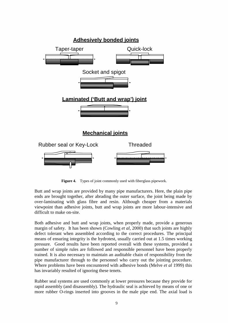
Several joining techniques are used for thermosetting pipes (Stringfellow, 1992). As shown in Figure 4, lengths of GRE pipe may be joined to fittings or to each other by
• Adhesive bonding, • Laminating (butt and wrap joints) or • By mechanical means, such as the rubber seal joint or the threaded
joint
Adhesively bonded joints may be of the taper-taper, socket and spigot or parallel (Quick-Lock) type. In each case, the socket may be either filament wound or moulded. Alternatively the socket may be directly moulded into the end of a straight length of filament wound pipe. The spigot end of the pipe is prepared by machining or shaving to the required dimensions and shape. For field or on-site joints, special shaving tools are provided for this. The joint is made by coating with adhesive (usually epoxy), assembly and elevated temperature curing using a heating blanket. Joints of this type are very common in the oil industry, both onshore and offshore. Bonding is also used to assemble flanges onto GRE pipework for subsequent attachment to other parts of the system. Flange joints are often used where easy disassembly is required.
8
Adhesively bonded joints
Taper-taper Quick-lock
Socket and spigot
Laminated (‘Butt and wrap’) joint
Mechanical joints
Rubber seal or Key-Lock Threaded
Figure 4. Types of joint commonly used with fiberglass pipework.
Butt and wrap joints are provided by many pipe manufacturers. Here, the plain pipe ends are brought together, after abrading the outer surface, the joint being made by over-laminating with glass fibre and resin. Although cheaper from a materials viewpoint than adhesive joints, butt and wrap joints are more labour-intensive and difficult to make on-site.
Both adhesive and butt and wrap joints, when properly made, provide a generous margin of safety. It has been shown (Cowling et al, 2000) that such joints are highly defect tolerant when assembled according to the correct procedures. The principal means of ensuring integrity is the hydrotest, usually carried out at 1.5 times working pressure. Good results have been reported overall with these systems, provided a number of simple rules are followed and responsible personnel have been properly trained. It is also necessary to maintain an auditable chain of responsibility from the pipe manufacturer through to the personnel who carry out the jointing procedure. Where problems have been encountered with adhesive bonds (Melve et al 1999) this has invariably resulted of ignoring these tenets.
Rubber seal systems are used commonly at lower pressures because they provide for rapid assembly (and disassembly). The hydraulic seal is achieved by means of one or more rubber O-rings inserted into grooves in the male pipe end. The axial load is
9
supported by a cylindrical key, often of nylon, inserted through a tangential hole in the socket wall, into preformed tangential grooves in the male and female end of the tube. The Ameron Key-lock™ system is a good example. Rubber seal joints enable long pipe runs to be laid with low handling and labour costs. The joint itself can accommodate a few degrees of flexure, making it possible to lay the system over ground with minimal preparation. The pressure rating of the joint can be improved by the use of more than one key.
For higher pressure applications, socket and spigot joints with moulded threads are successfully used, sometimes in conjunction with a thread sealant or adhesive. The thread design is often similar to the API tapered threads used with steel tubing.
3.1.2 Steel strip laminate (SSL) pipe
The effective safety factor on GRE pipe is quite high, with the result that larger diameter high pressure pipes tend to have wall thicknesses that can be inconvenient for manufacture and for handling. Steel strip laminate (SSL) pipe is a recent hybrid development that overcomes this problem (Friedrich, 1999). SSL pipe comprises conventional glass/epoxy bore and outer layers, but most of the internal load-bearing laminate is replaced by helically wound layers of high tensile steel strip. The advantage of this type of construction is that, despite its higher density compared with GRE, the steel strip can be operated at a much higher proportion of its UTS than the GRE, resulting in an overall lighter and more cost-effective structure. Good bonding between the steel strip layers is ensured by the use of adhesive technology originally developed for rocket motor casings. SSL is a true composite in the sense that the GRE is required to protect the steel strip from corrosion.
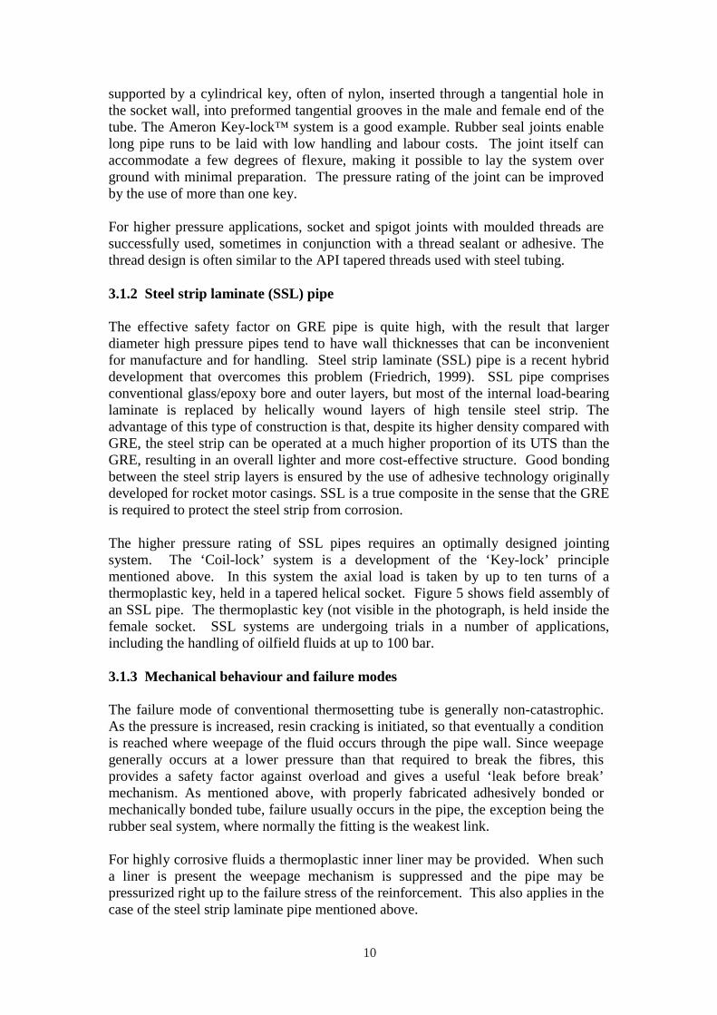
The higher pressure rating of SSL pipes requires an optimally designed jointing system. The ‘Coil-lock’ system is a development of the ‘Key-lock’ principle mentioned above. In this system the axial load is taken by up to ten turns of a thermoplastic key, held in a tapered helical socket. Figure 5 shows field assembly of an SSL pipe. The thermoplastic key (not visible in the photograph, is held inside the female socket. SSL systems are undergoing trials in a number of applications, including the handling of oilfield fluids at up to 100 bar.
3.1.3 Mechanical behaviour and failure modes
The failure mode of conventional thermosetting tube is generally non-catastrophic. As the pressure is increased, resin cracking is initiated, so that eventually a condition is reached where weepage of the fluid occurs through the pipe wall. Since weepage generally occurs at a lower pressure than that required to break the fibres, this provides a safety factor against overload and gives a useful ‘leak before break’ mechanism. As mentioned above, with properly fabricated adhesively bonded or mechanically bonded tube, failure usually occurs in the pipe, the exception being the rubber seal system, where normally the fitting is the weakest link.
For highly corrosive fluids a thermoplastic inner liner may be provided. When such a liner is present the weepage mechanism is suppressed and the pipe may be pressurized right up to the failure stress of the reinforcement. This also applies in the case of the steel strip laminate pipe mentioned above.
10
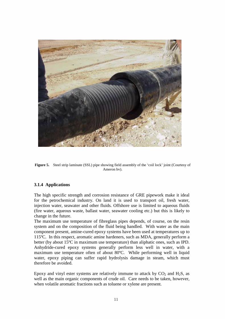
Figure 5. Steel strip laminate (SSL) pipe showing field assembly of the ‘coil lock’ joint (Courtesy of Ameron bv).
3.1.4 Applications
The high specific strength and corrosion resistance of GRE pipework make it ideal for the petrochemical industry. On land it is used to transport oil, fresh water, injection water, seawater and other fluids. Offshore use is limited to aqueous fluids (fire water, aqueous waste, ballast water, seawater cooling etc.) but this is likely to change in the future. The maximum use temperature of fibreglass pipes depends, of course, on the resin system and on the composition of the fluid being handled. With water as the main component present, amine-cured epoxy systems have been used at temperatures up to 115ºC. In this respect, aromatic amine hardeners, such as MDA, generally perform a better (by about 15ºC in maximum use temperature) than aliphatic ones, such as IPD. Anhydride-cured epoxy systems generally perform less well in water, with a maximum use temperature often of about 80ºC. While performing well in liquid water, epoxy piping can suffer rapid hydrolysis damage in steam, which must therefore be avoided.
Epoxy and vinyl ester systems are relatively immune to attack by CO2 and H2S, as well as the main organic components of crude oil. Care needs to be taken, however, when volatile aromatic fractions such as toluene or xylene are present.
11
Useful guidance on the areas where particular types of piping may be used is available from the in-house databases of established manufacturers, as well as from general publications (Stringfellow, 1992). High temperature performance under multiaxial load has been discussed by Hale et al. (2000).
Vinyl ester-based piping (often referred to as ‘epoxy vinyl ester’) is a strong competitor to epoxy in some highly corrosive applications and at lower temperatures. Its water resistance at higher temperature, however, is generally not as good as amine-cured epoxy. Use of pipes in acid or alkaline environments needs special consideration since, under these conditions, the glass fibre reinforcement may be attacked by contact with the fluid. Fortunately, the ionic species present in corrosive aqueous liquids are virtually insoluble in most thermosetting resins, so a tough, resinrich layer at the bore of the pipe (referred to as the ‘liner’) generally confers good resistance. Nevertheless, care needs to be taken to ensure that strain levels are such that liner cracking does not take place. Corrosive effects need to be carefully borne in mind if GRE tubing is occasionally used in contact with unusually corrosive products, such as those used for the ‘acidising’ of wells.
Fire water pipework has been a particularly successful application (Ciaraldi et al., 1991). Fire water systems, require to be repeatedly tested with seawater, which causes corrosion problems in the case of metallic pipes. Moreover, the metallic corrosion products, or wax additives used to prevent corrosion may cause blockage of the deluge nozzles. In this application GRE has achieved some success in replacing not only steel, but nickel alloys, stainless steel and even titanium.
GRE pipes show good fire integrity when filled with stagnant or flowing water. However, with many deluge systems there may be a period of up to 5 minutes duration between the outbreak of fire and the start-up of the deluge pumps when pipework is exposed to fire in the ‘dry’ or unfilled state. Unprotected GRE pipes can survive only up to about 2 minutes in this condition, so it is often necessary to provide them with passive fire protection. To overcome this difficulty, Ameron developed a fibreglass pipe system based on a siloxane/phenolic (PSX) resin alloy, which is capable of retaining its integrity for the required period. Fire resistance is sometimes further improved by incorporating a polypropylene film into the pipe wall. In fire, this results in a separated interface which hinders heat transfer through the pipe wall. . There has been interest in the use of GRE tube as a replacement for steel casings in wells. Although this application has yet to be fully realized, GRE tube is beginning to be used in the rehabilitation of water injection wells with corroded steel casings. This involves the insertion of a GRE tube into the well, as shown in Figure 6, followed by cement injection into space between the tube and the corroded casing in the lower part of the well, allowing the remainder of the GRE to be tensioned to minimize axial stress. Following this, the lower part of the casing wall may be perforated in the conventional manner and the well returned to service.
12
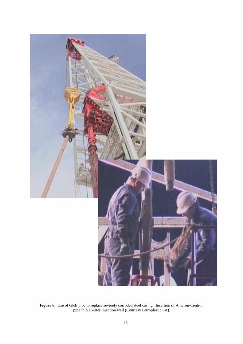
Figure 6. Use of GRE pipe to replace severely corroded steel casing. Insertion of Ameron-Centron pipe into a water injection well (Courtesy Petroplastic SA).
13

GRE caissons, Figure 7, are another interesting offshoot from GRE pipe technology and would seem to be an ideal application for composites. Caissons are used where service fluids enter or leave the sea. Caissons are situated in the splash zone and are subject to severe flexural fatigue due to wave loading. Steel caissons in this application can be prone to both fatigue and corrosion problems.
Figure 7. GRE caisson (courtesy of Odebrecht SLP and Ameron BV)
3.2 Tanks and Vessels
Composites have been used for some time for the manufacture of tanks for water and diesel storage. There are effective and conservative codes that enable both tanks and pressure vessels to be designed for moderate pressures (Anisdahl et al., 1999, BS4994, 1987; ASME, 1992). Since a key feature of most pressure vessel codes for composites is the allowable strain, it is probable that future construction will place greater emphasis on resin systems that display improved levels of elongation before cracking occurs in the composite.
The future is expected to bring more widespread use in tanks, as well as in vessels operating at higher pressures than at present. This will probably lead eventually to applications in separators and other high pressure processing equipment where thermal and corrosion requirements can be very demanding.
14
3.3 Flexible Thermosetting Tube
Composite coil tube, as typified by ‘Fiberspar’ (Fowler, 1997; Fowler et al., 1998; Quigley et al., 1999) and ‘Compipe’ (Boye Hansen and Asdal, 1997; Asdal and Boye Hansen, 1999) is a new product, developed initially in response to the need for a non-metallic replacement for steel coil tubing. This product is used for high pressure down-hole applications in which the tube is repeatedly transported on a drum, uncoiled and forced into the well. It is then removed, and re-coiled for further use. The life of the steel product is limited by low cycle fatigue associated with repeated plastic deformations caused by the coiling and uncoiling. Another driving factor in this development was the advent of long horizontal wells, which proved difficult for the insertion of certain types of steel coil tube.
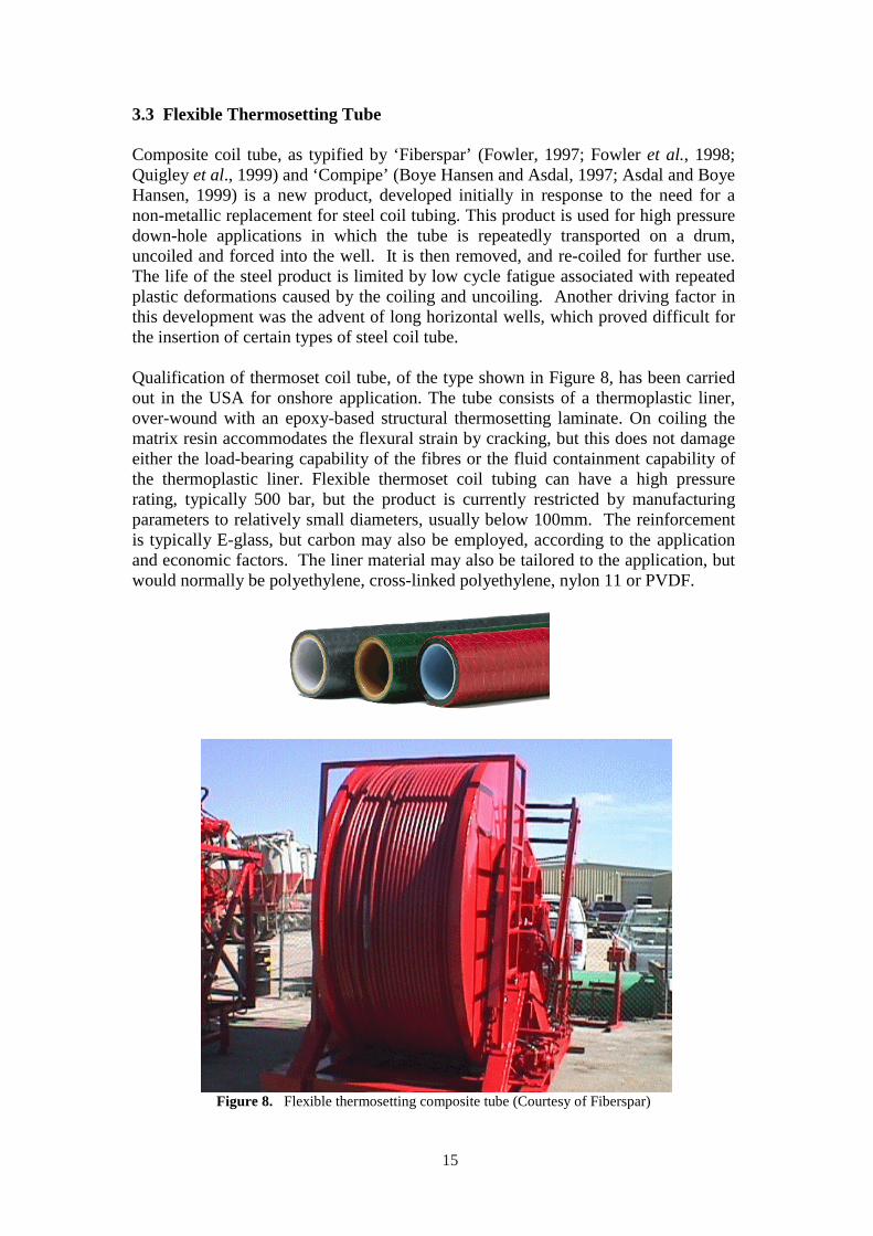
Qualification of thermoset coil tube, of the type shown in Figure 8, has been carried out in the USA for onshore application. The tube consists of a thermoplastic liner, over-wound with an epoxy-based structural thermosetting laminate. On coiling the matrix resin accommodates the flexural strain by cracking, but this does not damage either the load-bearing capability of the fibres or the fluid containment capability of the thermoplastic liner. Flexible thermoset coil tubing can have a high pressure rating, typically 500 bar, but the product is currently restricted by manufacturing parameters to relatively small diameters, usually below 100mm. The reinforcement is typically E-glass, but carbon may also be employed, according to the application and economic factors. The liner material may also be tailored to the application, but would normally be polyethylene, cross-linked polyethylene, nylon 11 or PVDF.
Figure 8. Flexible thermosetting composite tube (Courtesy of Fiberspar)
15
A wide range of additional onshore and offshore applications is now envisaged for flexible thermosetting pipe, including umbilical components, methanol injection lines, heater lines and choke and kill lines. Techniques have recently been developed for sub sea well intervention using tubes of this type.
3.4 Reinforced Thermoplastic Pipework (RTP)
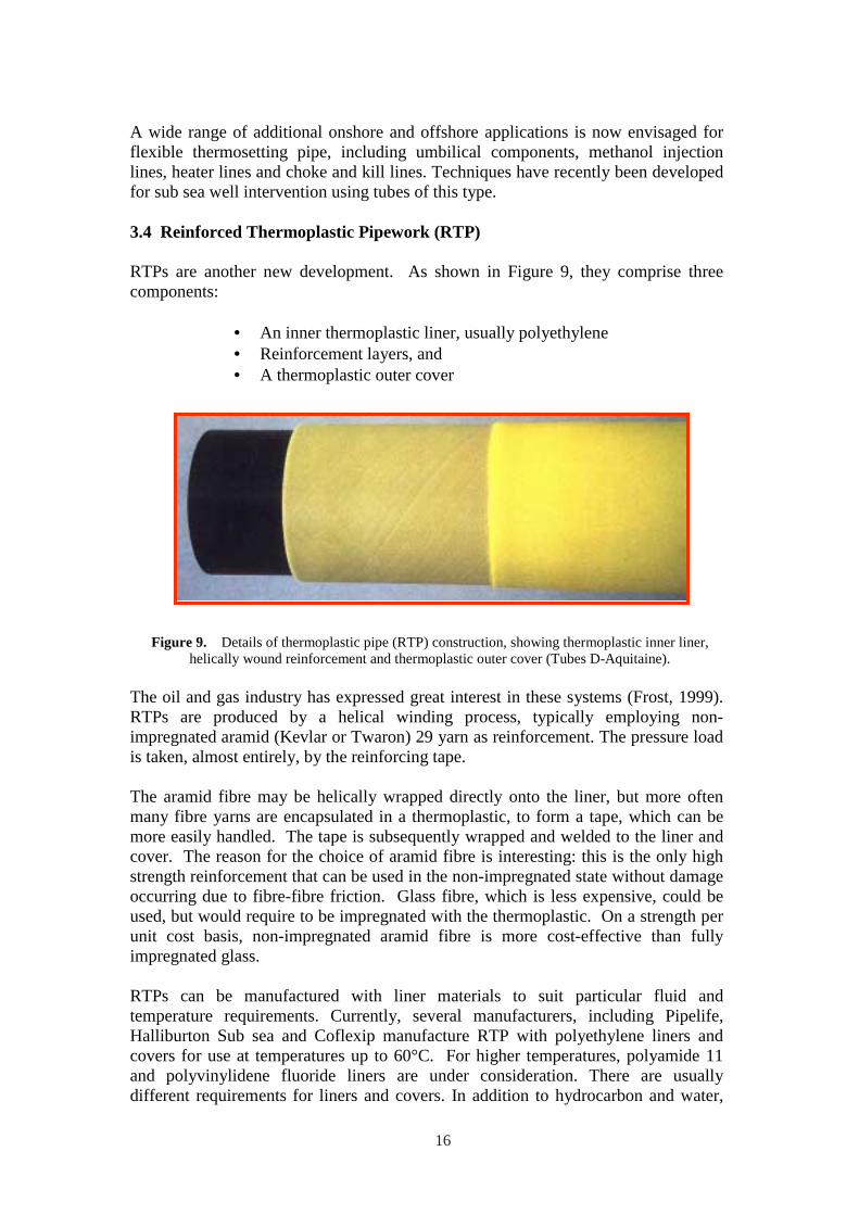
RTPs are another new development. As shown in Figure 9, they comprise three components:
• An inner thermoplastic liner, usually polyethylene • Reinforcement layers, and • A thermoplastic outer cover
Figure 9. Details of thermoplastic pipe (RTP) construction, showing thermoplastic inner liner, helically wound reinforcement and thermoplastic outer cover (Tubes D-Aquitaine).
The oil and gas industry has expressed great interest in these systems (Frost, 1999). RTPs are produced by a helical winding process, typically employing nonimpregnated aramid (Kevlar or Twaron) 29 yarn as reinforcement. The pressure load is taken, almost entirely, by the reinforcing tape.
The aramid fibre may be helically wrapped directly onto the liner, but more often many fibre yarns are encapsulated in a thermoplastic, to form a tape, which can be more easily handled. The tape is subsequently wrapped and welded to the liner and cover. The reason for the choice of aramid fibre is interesting: this is the only high strength reinforcement that can be used in the non-impregnated state without damage occurring due to fibre-fibre friction. Glass fibre, which is less expensive, could be used, but would require to be impregnated with the thermoplastic. On a strength per unit cost basis, non-impregnated aramid fibre is more cost-effective than fully impregnated glass.
RTPs can be manufactured with liner materials to suit particular fluid and temperature requirements. Currently, several manufacturers, including Pipelife, Halliburton Sub sea and Coflexip manufacture RTP with polyethylene liners and covers for use at temperatures up to 60°C. For higher temperatures, polyamide 11 and polyvinylidene fluoride liners are under consideration. There are usually different requirements for liners and covers. In addition to hydrocarbon and water,
16
the liner may be exposed to corrosive agents such as CO2 or H2S. The outer cover, on the other hand, may be subject to UV degradation or abrasive effects.
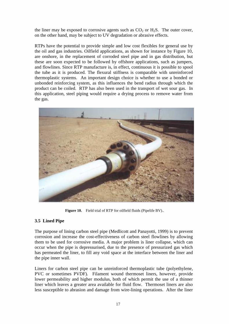
RTPs have the potential to provide simple and low cost flexibles for general use by the oil and gas industries. Oilfield applications, as shown for instance by Figure 10, are onshore, in the replacement of corroded steel pipe and in gas distribution, but these are soon expected to be followed by offshore applications, such as jumpers, and flowlines. Since RTP manufacture is, in effect, continuous it is possible to spool the tube as it is produced. The flexural stiffness is comparable with unreinforced thermoplastic systems. An important design choice is whether to use a bonded or unbonded reinforcing system, as this influences the bend radius through which the product can be coiled. RTP has also been used in the transport of wet sour gas. In this application, steel piping would require a drying process to remove water from the gas.
Figure 10. Field trial of RTP for oilfield fluids (Pipelife BV)..
3.5 Lined Pipe
The purpose of lining carbon steel pipe (Medlicott and Panayotti, 1999) is to prevent corrosion and increase the cost-effectiveness of carbon steel flowlines by allowing them to be used for corrosive media. A major problem is liner collapse, which can occur when the pipe is depressurised, due to the presence of pressurized gas which has permeated the liner, to fill any void space at the interface between the liner and the pipe inner wall.
Liners for carbon steel pipe can be unreinforced thermoplastic tube (polyethylene, PVC or sometimes PVDF). Filament wound thermoset liners, however, provide lower permeability and higher modulus, both of which permit the use of a thinner liner which leaves a greater area available for fluid flow. Thermoset liners are also less susceptible to abrasion and damage from wire-lining operations. After the liner
17
has been placed within the pipe the space between the liner and the pipe wall is injected with a cementitious or polymeric grout.
3.6 Rigid Risers
Rigid riser systems are typically large diameter (250-550mm) high performance tubes which undergo complex loadings and which have pressure ratings of the order of 1000 bar. They can employ a range of high strength and duplex steels, as well as titanium, assembled from short sections into considerable lengths. Rigid metallic risers are widely used on all offshore platforms in both shallow and deep water. With increasing water depth, however, especially in excess of 1000 metres, both platform designs and the design of the risers begin to become highly weightsensitive.
The benefits of weight reduction through the introduction of composite risers have been known for some time, but the advent of deepwater is providing increased impetus for the use of these materials. The advantages include:
• Lower cost of added buoyancy (such as syntactic foam) required to reduce riser self-weight
• Reduction in riser external cross-section, leading to lower drag forces and reduced tension
• Reduction in the cost of tensioning equipment • On-going savings in topside weight
Development of composite rigid risers has been driven by a number of companies, including Conoco, Petrobras, Shell and Statoil. In the USA, several companies, including Lincoln Composites and Northrop Grumman have been involved in riser development. In Europe the Institut Français du Pétrole (IFP) has taken a leading role in research on prototype riser systems (Sparks et al. 1995).
Most proposed composite riser designs have certain common features:
• A metallic or elastomeric inner liner • near-axial reinforcement, often carbon fibre, to carry tensile and
bending loads • Near-hoop reinforcement, S-glass or carbon, to carry the pressure
load • A jointing system to allow many lengths to be put together
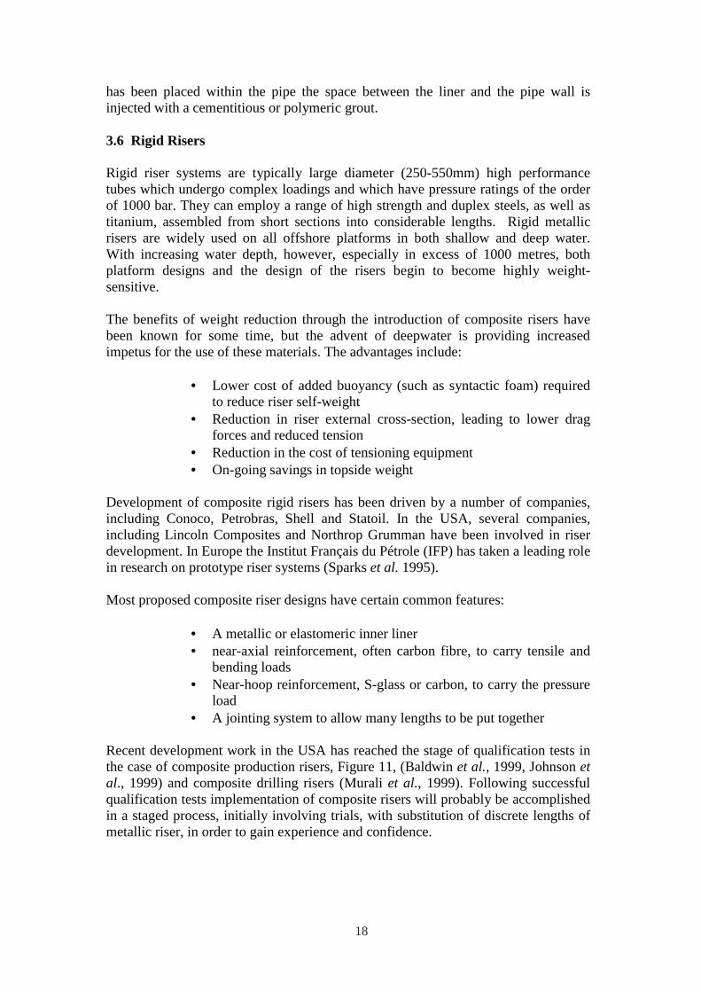
Recent development work in the USA has reached the stage of qualification tests in the case of composite production risers, Figure 11, (Baldwin et al., 1999, Johnson et al., 1999) and composite drilling risers (Murali et al., 1999). Following successful qualification tests implementation of composite risers will probably be accomplished in a staged process, initially involving trials, with substitution of discrete lengths of metallic riser, in order to gain experience and confidence.
18
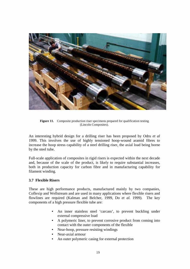
Figure 11. Composite production riser specimens prepared for qualification testing (Lincoln Composites).
An interesting hybrid design for a drilling riser has been proposed by Odru et al 1999. This involves the use of highly tensioned hoop-wound aramid fibres to increase the hoop stress capability of a steel drilling riser, the axial load being borne by the steel tube.
Full-scale application of composites in rigid risers is expected within the next decade and, because of the scale of the product, is likely to require substantial increases, both in production capacity for carbon fibre and in manufacturing capability for filament winding.
3.7 Flexible Risers
These are high performance products, manufactured mainly by two companies, Coflexip and Wellstream and are used in many applications where flexible risers and flowlines are required (Kalman and Belcher, 1999, Do et al. 1999). The key components of a high pressure flexible tube are:
• An inner stainless steel ‘carcass’, to prevent buckling under external compressive load
• A polymeric liner, to prevent corrosive product from coming into contact with the outer components of the flexible
• Near-hoop, pressure resisting windings • Near-axial armour • An outer polymeric casing for external protection
19
These tubes achieve their flexibility by virtue of the fact that the load-bearing components are free to move relative to one another. Currently, few composite components are used in flexible riser construction, the load-bearing elements usually being of high strength steel. There are, however, significant opportunities for the use of unidirectional carbon fibre composite elements, which may be either thermoplastic or thermoset-based, in the armour for weight-saving, and because of corrosion problems with steel. This could represent a significant future application for composites.
3.8 High Pressure Accumulator Bottles
To accommodate the relative motions between the platform and the riser, in the case of tension leg platforms, a telescopic joint is used at the upper extremity of each riser. These joints require a tensioning system capable of storing and releasing large amounts of energy as movement takes place. Tension is applied through gaspressurized tensioners with accumulator bottles, as shown in Figure 12. In older designs steel accumulator bottles were used but, recently, considerable success has been achieved with composite bottles. Lincoln Composites has now supplied accumulator systems to several TLPs and it is reported that, despite conservative design margins (ASME, 1992), the composite bottles offer significant weight and cost savings (Baldwin et al., 1999), being less than 1/3 of the weight of equivalent steel bottles. While the design pressure is just over 200 bar, the maximum permitted by the ASME code, short term burst pressures in excess of 1,100 bar are reported. Resistance to substantial cyclic pressure loading is required, over a design temperature range of –30 to +65ºC.
Figure 12. Riser tensioning assembly on a tension leg platform, showing composite high pressure gas accumulator bottles (Lincoln Composites).
20
The design of the accumulators owes much to technology previously developed for gas tanks for natural gas vehicles. Injection moulded butt-welded polyethylene liners are employed, over which the load-bearing laminate layers are wound. Excellent fatigue resistance is claimed through the use of carbon fibre as the main load-bearing reinforcement. Damage tolerance and handling resistance is achieved through the use of glass fibre to provide bulk and external protection. Over 120 bottles, up to 2.6m long, 0.5m in diameter and weighing up to 250 kg each, are now in use on platforms in the Gulf of Mexico.
The same type of filament winding technology could eventually be applied to the manufacture of separators. The main problem here is the larger size of vessel and the high temperature of the well fluids. Nevertheless, developments are expected in this area, perhaps accelerated by in terst in seabed processing.
3.9 Repair of metallic tubulars
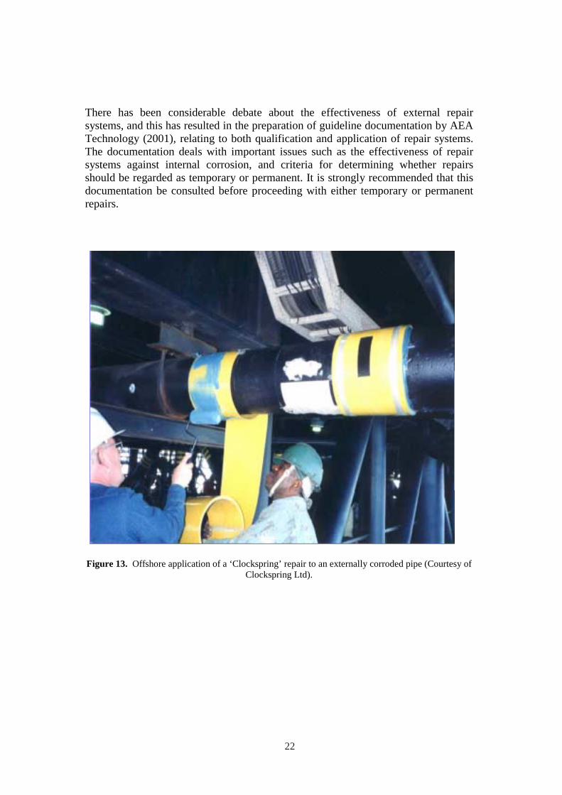
The problem of corroded steel structures, especially pipework, is widespread in the oil and gas industry and there is considerable interest in temporary and permanent rehabilitation of such structures (Gibson, 2000, 2001, Mableson et al. 2000). A number of composite material solutions have been developed to address this problem. The majority of rehabilitation solutions for offshore use involve adding reinforcement to the exterior of the pipe or structure, to compensate for the loss of section thickness due to corrosion. The most successful of these is the ‘Clockspring’ system, developed in the USA by the Gas Research Institute. This system is widely used to restore hoop stress-bearing capability to externally corroded, or damaged pipework. Clockspring comprises a unidirectional glass fibre laminate, supplied in the form in the form of a spiral helix.
Figure 13 shows Clockspring being applied offshore to an externally corroded pipe. Application involves first cleaning the surface and filling external pits or damage, to allow stress to be transmitted from the pipe to the repair. Following this the Clockspring laminate is wound around the pipe, while being coated with adhesive, which is allowed to cure. This is a highly effective means of permanently restoring hoop stress-bearing capability. Although several Clockspring repairs may be applied adjacent to one another, the system does not provide axial or flexural stress bearing capability. Its use is also difficult on bends, and limited mainly to cases where the corrosion is external.
Commercial systems are also available (Mableson et al. 2000) which allow the application of composite laminate with multidirectional fibre orientation, to permit rehabilitation of both axial and hoop stress-bearing capability. Companies which supply such systems include DML, Vosper Thornycroft and Walker Technical Resources. Figure 14 shows the DML repair system, which comprises carbon fibre reinforcement, applied dry to the repair area, then impregnated using a vacuum infusion technique. This is a derivative of a repair system originally developed for repairing corroded structural members. Figure 15 shows employees being trained in the use of a glass fibre-based laminate repair system.
21
There has been considerable debate about the effectiveness of external repair systems, and this has resulted in the preparation of guideline documentation by AEA Technology (2001), relating to both qualification and application of repair systems. The documentation deals with important issues such as the effectiveness of repair systems against internal corrosion, and criteria for determining whether repairs should be regarded as temporary or permanent. It is strongly recommended that this documentation be consulted before proceeding with either temporary or permanent repairs.
Figure 13. Offshore application of a ‘Clockspring’ repair to an externally corroded pipe (Courtesy of Clockspring Ltd).
22
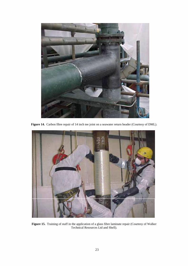
Figure 14. Carbon fibre repair of 14 inch tee joint on a seawater return header (Courtesy of DML).
Figure 15. Training of staff in the application of a glass fibre laminate repair (Courtesy of Walker Technical Resources Ltd and Shell).
23

24
4. STRUCTURAL APPLICATIONS
4.1 Blast and Fire Protection
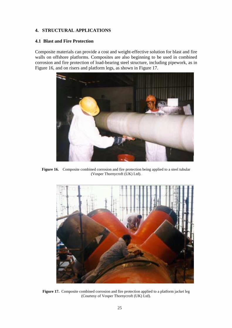
Composite materials can provide a cost and weight-effective solution for blast and fire walls on offshore platforms. Composites are also beginning to be used in combined corrosion and fire protection of load-bearing steel structure, including pipework, as in Figure 16, and on risers and platform legs, as shown in Figure 17.
Figure 16. Composite combined corrosion and fire protection being applied to a steel tubular (Vosper Thornycroft (UK) Ltd).
Figure 17. Composite combined corrosion and fire protection applied to a platform jacket leg (Courtesy of Vosper Thornycroft (UK) Ltd).
25
When used in a sandwich configuration, to maximize stiffness and fire integrity they can achieve a weight advantage of the order of 30% compared with traditional corrugated steel fire and blast wall structures. While composite panels are generally more expensive than carbon steel ones they do not corrode or require painting. They are usually less expensive than stainless steel panels.
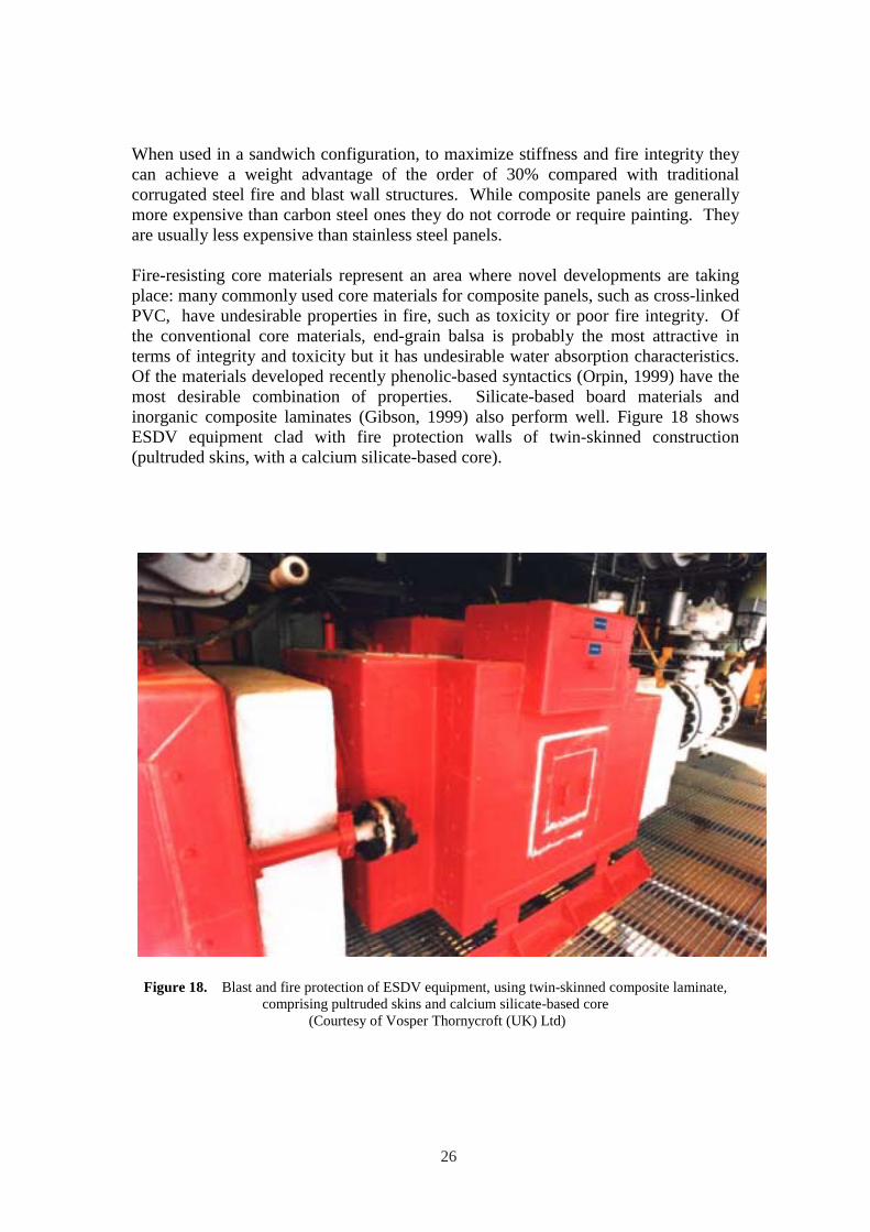
Fire-resisting core materials represent an area where novel developments are taking place: many commonly used core materials for composite panels, such as cross-linked PVC, have undesirable properties in fire, such as toxicity or poor fire integrity. Of the conventional core materials, end-grain balsa is probably the most attractive in terms of integrity and toxicity but it has undesirable water absorption characteristics. Of the materials developed recently phenolic-based syntactics (Orpin, 1999) have the most desirable combination of properties. Silicate-based board materials and inorganic composite laminates (Gibson, 1999) also perform well. Figure 18 shows ESDV equipment clad with fire protection walls of twin-skinned construction (pultruded skins, with a calcium silicate-based core).
Figure 18. Blast and fire protection of ESDV equipment, using twin-skinned composite laminate,comprising pultruded skins and calcium silicate-based core
(Courtesy of Vosper Thornycroft (UK) Ltd)
26
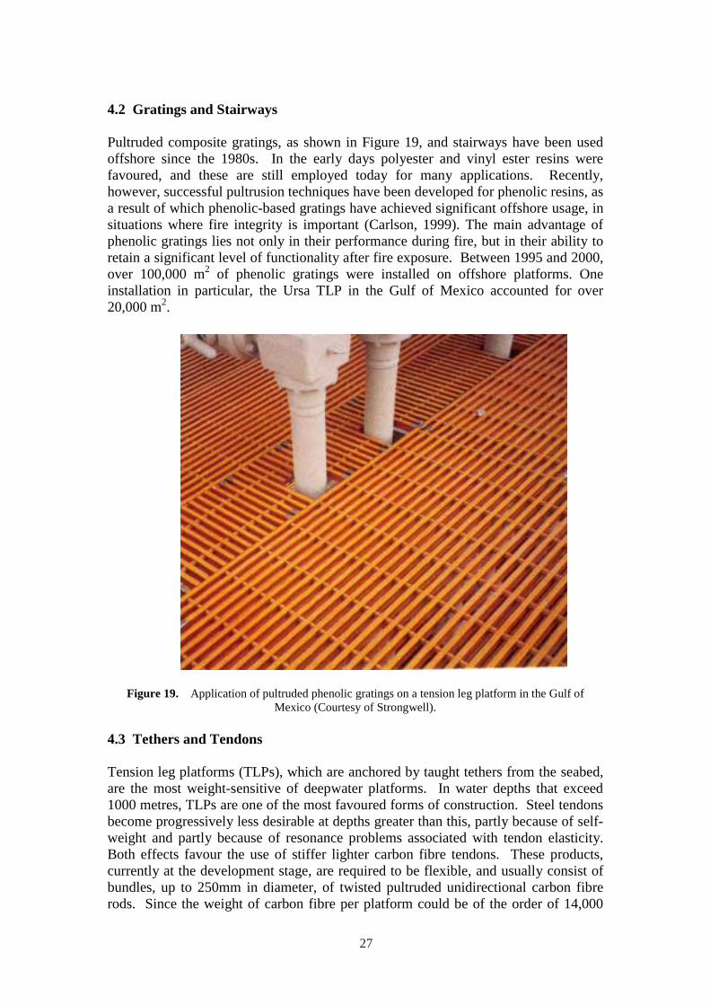
4.2 Gratings and Stairways
Pultruded composite gratings, as shown in Figure 19, and stairways have been used offshore since the 1980s. In the early days polyester and vinyl ester resins were favoured, and these are still employed today for many applications. Recently, however, successful pultrusion techniques have been developed for phenolic resins, as a result of which phenolic-based gratings have achieved significant offshore usage, in situations where fire integrity is important (Carlson, 1999). The main advantage of phenolic gratings lies not only in their performance during fire, but in their ability to retain a significant level of functionality after fire exposure. Between 1995 and 2000, over 100,000 m2 of phenolic gratings were installed on offshore platforms. One installation in particular, the Ursa TLP in the Gulf of Mexico accounted for over 20,000 m2.
Figure 19. Application of pultruded phenolic gratings on a tension leg platform in the Gulf of Mexico (Courtesy of Strongwell).
4.3 Tethers and Tendons
Tension leg platforms (TLPs), which are anchored by taught tethers from the seabed, are the most weight-sensitive of deepwater platforms. In water depths that exceed 1000 metres, TLPs are one of the most favoured forms of construction. Steel tendons become progressively less desirable at depths greater than this, partly because of selfweight and partly because of resonance problems associated with tendon elasticity. Both effects favour the use of stiffer lighter carbon fibre tendons. These products, currently at the development stage, are required to be flexible, and usually consist of bundles, up to 250mm in diameter, of twisted pultruded unidirectional carbon fibre rods. Since the weight of carbon fibre per platform could be of the order of 14,000
27

tonnes (Fischer and Salama, 1999) this represents a very large potential composites market. The difficulty, as with a number of other potential applications for carbon fibre, relates to current annual production capacity for the material.
28
5. MAJOR LOAD-BEARING STRUCTURAL USE OF COMPOSITES OFFSHORE
It has long been acknowledged that composite materials have the potential to be used in major load-bearing structure offshore and it is probable that applications will evolve within the next few years. However, as mentioned at the beginning of this review, there have been a number of factors that have hindered this and it is worthwhile considering them. The problems which still remain relate to designer familiarity, industry infrastructure and the difficulty of scaling up traditional composite fabrication processes so as to be able to make very large structures.
A recent study by Maunsell Structural Plastics and Odebrecht SLP, involved the redesign of the topside of the Davy-Bessemer monopod platforms (shown in Figure 2) to make the maximum possible structural use of composites (Churchman et al., 1999; ARP, 2000). Following the decision to carry out a design study, there was extensive discussion regarding the type of platform that would form the subject of the study. The small Davy-Bessemer platforms were chosen, at least partly, because their scale would minimise the anticipated difficulties involving fabrication of large structures in composites. The choice of a ‘not normally manned’ facility also simplified certain safety requirements in regard to fire and accommodation.
Despite the relatively small scale of the structure, by offshore standards, one of the principal design difficulties was to determine a viable and cost-effective route for the manufacture of the main vertical and decking elements. For the decking, it was determined that a structure of interlocking beams, that allowed some sharing of load between transverse elements, would be the most favourable. Several options were discussed and costings obtained from the industry before one particular structural option, the composite-wrapped pultruded cellular beam was chosen. One reason for this choice was that, at the time of the project, no suitable pultruded section of sufficient depth was available. It was recognised that, depending on the capabilities of individual manufacturers, there could be alternatives to the wrapped pultruded beam concept- one of these being large custom-built structural elements fabricated using RTM or vacuum infusion technology.
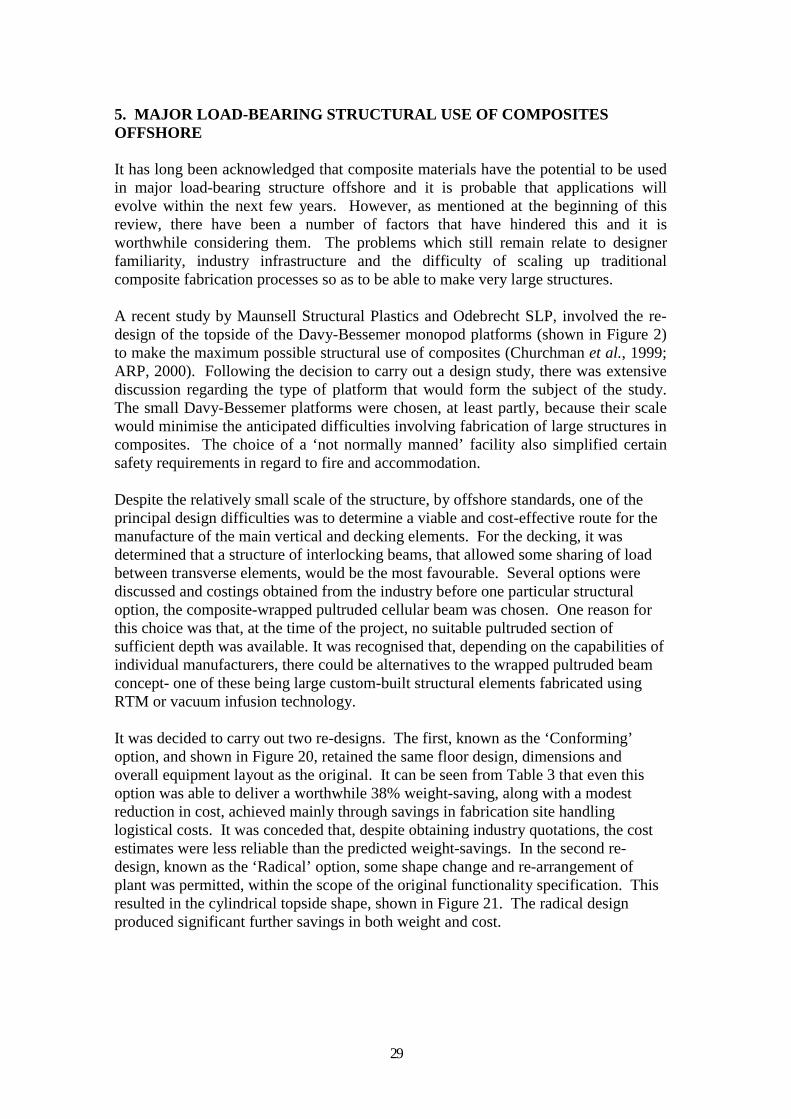
It was decided to carry out two re-designs. The first, known as the ‘Conforming’ option, and shown in Figure 20, retained the same floor design, dimensions and overall equipment layout as the original. It can be seen from Table 3 that even this option was able to deliver a worthwhile 38% weight-saving, along with a modest reduction in cost, achieved mainly through savings in fabrication site handling logistical costs. It was conceded that, despite obtaining industry quotations, the cost estimates were less reliable than the predicted weight-savings. In the second redesign, known as the ‘Radical’ option, some shape change and re-arrangement of plant was permitted, within the scope of the original functionality specification. This resulted in the cylindrical topside shape, shown in Figure 21. The radical design produced significant further savings in both weight and cost.
29
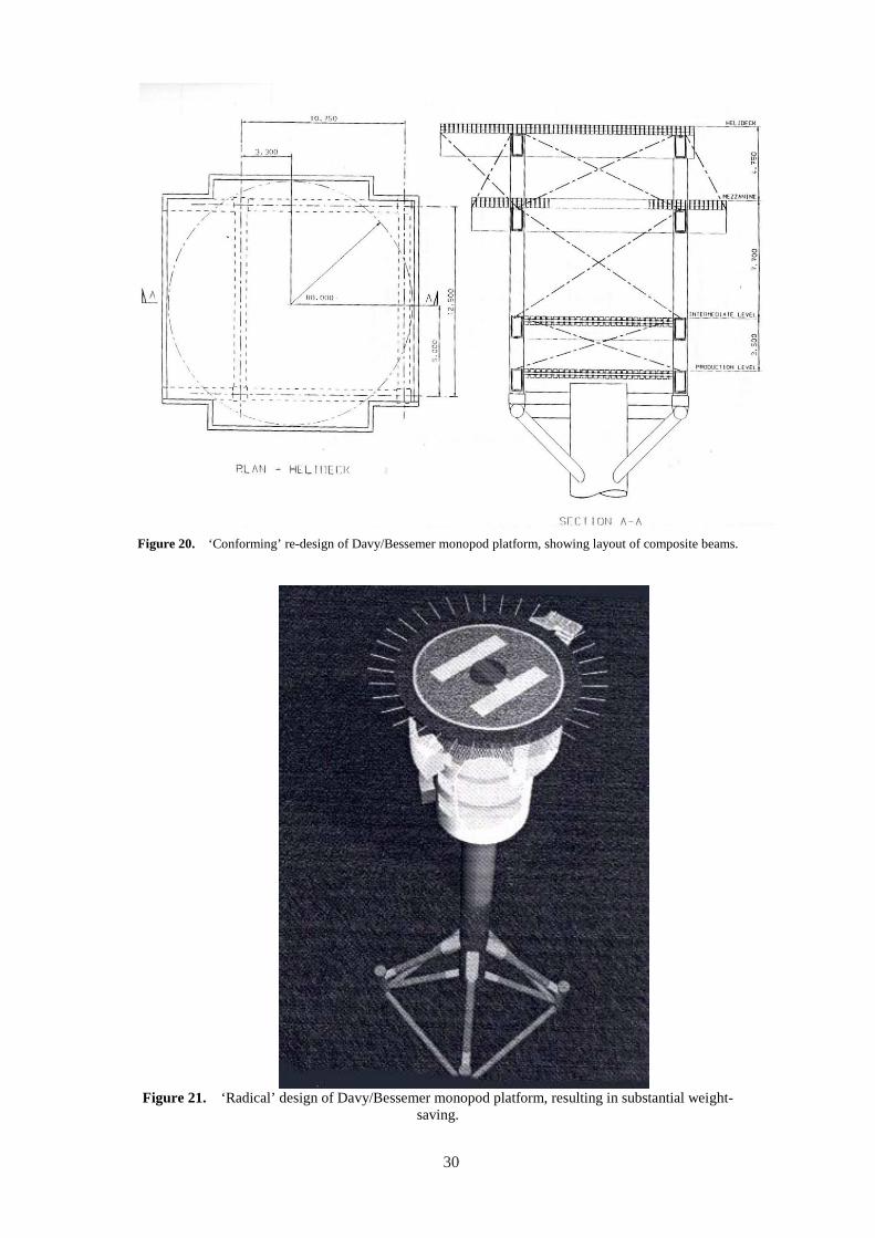
Figure 20. ‘Conforming’ re-design of Davy/Bessemer monopod platform, showing layout of composite beams.
Figure 21. ‘Radical’ design of Davy/Bessemer monopod platform, resulting in substantial weightsaving.
30
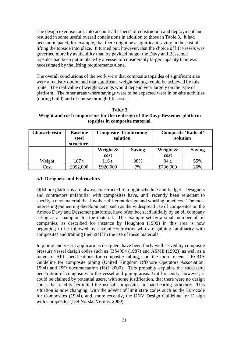
The design exercise took into account all aspects of construction and deployment and resulted in some useful overall conclusions in addition to those in Table 3. It had been anticipated, for example, that there might be a significant saving in the cost of lifting the topside into place. It turned out, however, that the choice of lift vessels was governed more by availability than by payload range- the Davy and Bessemer topsides had been put in place by a vessel of considerably larger capacity than was necessitated by the lifting requirements alone.
The overall conclusions of the work were that composite topsides of significant size were a realistic option and that significant weight-savings could be achieved by this route. The real value of weight-savings would depend very largely on the type of platform. The other areas where savings were to be expected were in on-site activities (during build) and of course through-life costs.
Table 3 Weight and cost comparisons for the re-design of the Davy-Bessemer platform
topsides in composite material.
Characteristic Baseline steel
structure.
Composite ‘Conforming’ solution.
Composite ‘Radical’ solution
Weight & cost
Saving Weight & cost
Saving
Weight 187 t. 116 t. 38% 84 t. 55% Cost £992,000 £920,000 7% £736,000 26%
5.1 Designers and Fabricators
Offshore platforms are always constructed to a tight schedule and budget. Designers and contractors unfamiliar with composites have, until recently been reluctant to specify a new material that involves different design and working practices. The most interesting pioneering developments, such as the widespread use of composites on the Amoco Davy and Bessemer platforms, have often been led initially by an oil company acting as a champion for the material. The example set by a small number of oil companies, as described for instance by Houghton (1999) in this area is now beginning to be followed by several contractors who are gaining familiarity with composites and training their staff in the use of these materials.
In piping and vessel applications designers have been fairly well served by composite pressure vessel design codes such as (BS4994 (1987) and ASME (1992)) as well as a range of API specifications for composite tubing, and the more recent UKOOA Guideline for composite piping (United Kingdom Offshore Operators Association, 1994) and ISO documentation (ISO 2000). This probably explains the successful penetration of composites in the vessel and piping areas. Until recently, however, it could be claimed by potential users, with some justification, that there were no design codes that readily permitted the use of composites in load-bearing structure. This situation is now changing, with the advent of limit state codes such as the Eurocode for Composites (1994), and, more recently, the DNV Design Guideline for Design with Composites (Det Norske Veritas, 2000).
31
5.2 Composites Industry Infrastructure
The composites industry, by and large, consists of small to medium sized enterprises operating a wide variety of processes (Sims, 2001). While this results in a useful flexibility of approach and a flair for innovation, these factors prove disadvantageous when it comes to dealing with the offshore industry and its supply chain. It is no coincidence that the companies that have achieved greatest success in supplying the offshore industry tend to be larger organisations with existing contacts with design houses and contractors. The answer to these problems must lie in improved alliances between suppliers, or groups of suppliers and contractors.
There are also some potential problems with capacity. Some of the more promising applications for offshore products, including risers and tethers, as mentioned above, involve volumes that would require a step change in production capacity, not only for composite manufacture, but also in the supply of carbon fibre. There is evidence that the carbon fibre industry, stimulated by growth in several engineering areas, is on the threshold of such a change. One encouraging development is the improving availability of new low cost carbon fibre products.
5.3 Scale-up of Fabrication Processes
Of the many processes that can be used for fabricating composite parts, only a few are capable of being scaled-up to produce structures of the size needed for structural items on offshore platforms. These processes are:
• Contact moulding (or hand-laminating) • Resin infusion processes • Pultrusion, and • Filament winding
Currently, the largest composite structures are glass fibre minehunter vessels, up to 55 metres in length. These vessels clearly demonstrate the problems of designing and making large composite structures, most notably the difficulties of designing effective joints and of achieving the necessary structural stiffness with glass fibre. They also demonstrate the solutions to these problems through the development of special joint configurations and the use of twin-skinned or stiffened skin structures. Although the main process to date has been contact moulding, environmental regulations and the need for improved quality of construction have led to the use of resin infusion processes (as typified by the proprietary SCRIMP or Seeman Composites Resin Infusion Moulding Process). Ship builders are making increasing use of processes of this type.
The move towards resin infusion is further demonstrated by the recent development in Sweden of carbon based-based corvette craft up to 70 metres in length with stealth capability (Gibson, 2001). These craft employ resin infusion throughout their hull structure in conjunction with carbon vinyl/vinyl ester and sandwich construction to achieve high stiffness. Clearly this type of construction would be viable for loadbearing structure offshore.
32
The key problem in the construction of large area decks for topside structures is the achievement of the required degree of stiffness. The depth of section required for a sandwich construction deck is currently greater than can easily be achieved using foam-cored sandwich, and sandwich cores may not, in general be capable of resisting the very large direct and shear loads involved with such a deck.
An alternative approach to deck design has been considered in the Advanced Research Partnership Composites Offshore programme (ARP, 2000). Instead of sandwich construction, it was found that a linked assembly of pultruded cellular elements could provide the required depth and stiffness of section. Added stiffening could be achieved through transverse connections between the cellular elements.
One promising recent development is the deep section pultruded box beam that has been achieved recently by Strongwell (Witcher, 1999).
6 PROPERTIES OF COMPOSITES RELEVANT TO OFFSHORE APPLICATIONS
6.1 Environmental and Fatigue Behaviour
Effective structural use of composites offshore requires an accurate knowledge of their behaviour under repeated loading and their response to marine environments. Fatigue performance has been reviewed recently by Konur and Matthews (1989) and, in relation to marine applications, by Scholte (1994). Given the need for accelerated generation of data on new resin and fibre systems, Kotsikos et al. (2000) undertook a series of studies on relevant composite systems, both dry and after an accelerated conditioning programme in seawater, the aim being to accurately define the strain limits for design.
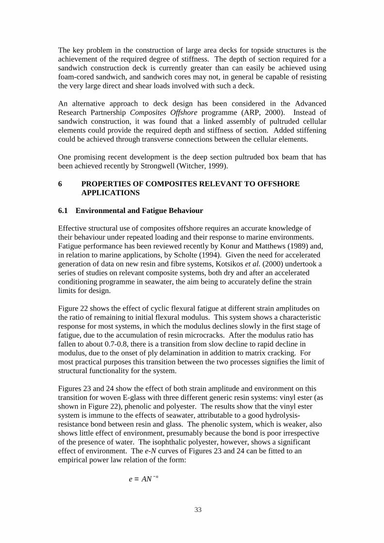
Figure 22 shows the effect of cyclic flexural fatigue at different strain amplitudes on the ratio of remaining to initial flexural modulus. This system shows a characteristic response for most systems, in which the modulus declines slowly in the first stage of fatigue, due to the accumulation of resin microcracks. After the modulus ratio has fallen to about 0.7-0.8, there is a transition from slow decline to rapid decline in modulus, due to the onset of ply delamination in addition to matrix cracking. For most practical purposes this transition between the two processes signifies the limit of structural functionality for the system.
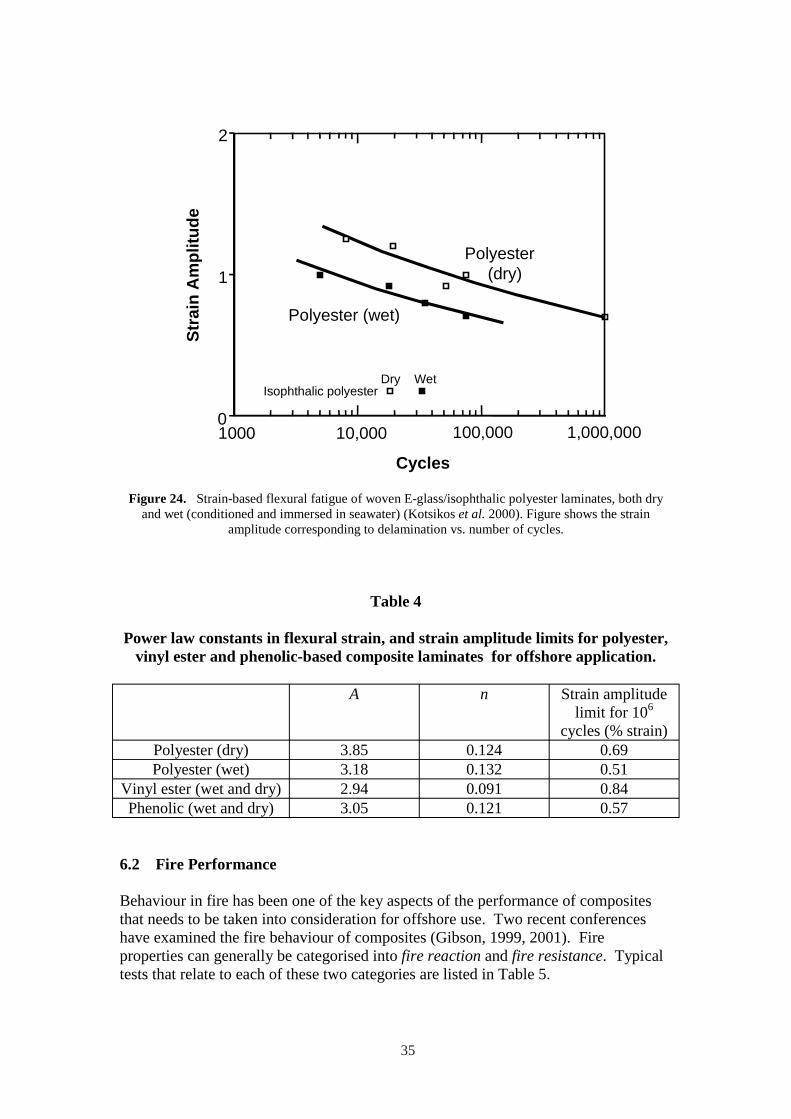
Figures 23 and 24 show the effect of both strain amplitude and environment on this transition for woven E-glass with three different generic resin systems: vinyl ester (as shown in Figure 22), phenolic and polyester. The results show that the vinyl ester system is immune to the effects of seawater, attributable to a good hydrolysisresistance bond between resin and glass. The phenolic system, which is weaker, also shows little effect of environment, presumably because the bond is poor irrespective of the presence of water. The isophthalic polyester, however, shows a significant effect of environment. The e-N curves of Figures 23 and 24 can be fitted to an empirical power law relation of the form:
e = AN −n
33
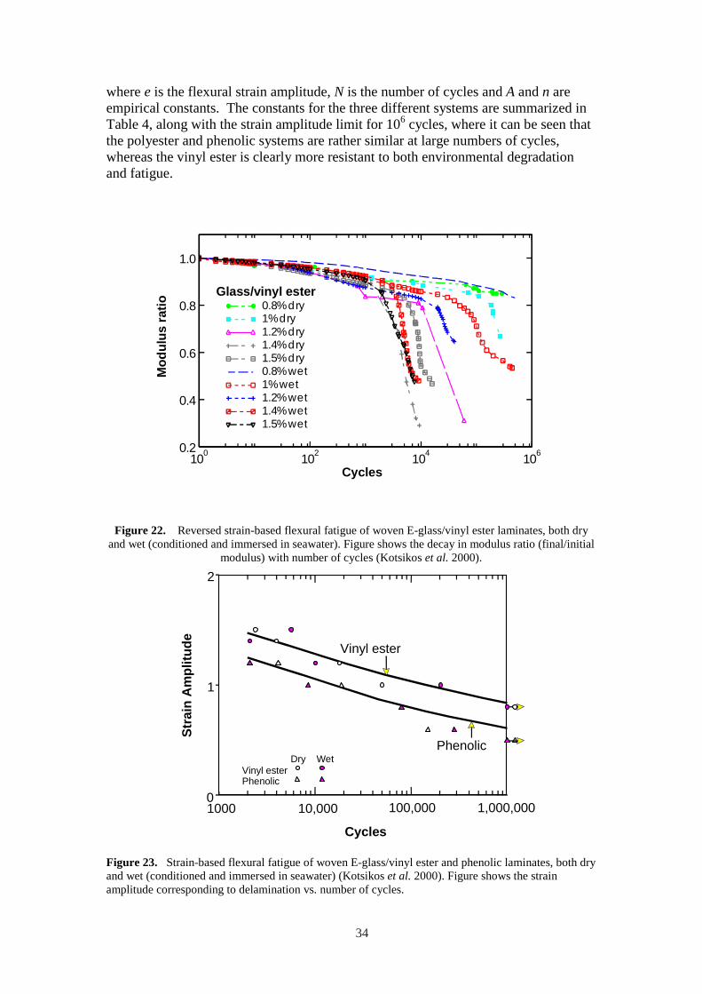
where e is the flexural strain amplitude, N is the number of cycles and A and n are empirical constants. The constants for the three different systems are summarized in Table 4, along with the strain amplitude limit for 106 cycles, where it can be seen that the polyester and phenolic systems are rather similar at large numbers of cycles, whereas the vinyl ester is clearly more resistant to both environmental degradation and fatigue.
0.2
0.4
0.6
0.8
1.0
0.8% dry 1% dry 1.2% dry 1.4% dry 1.5% dry 0.8% wet 1% wet 1.2% wet 1.4% wet 1.5% wet
Mod
ulus
ratio
Glass/vinyl ester
100 102 104 106
Cycles
Figure 22. Reversed strain-based flexural fatigue of woven E-glass/vinyl ester laminates, both dry and wet (conditioned and immersed in seawater). Figure shows the decay in modulus ratio (final/initial
modulus) with number of cycles (Kotsikos et al. 2000).
0
1
2
VinylDry
Vinyl ester
Phenolic
Stra
in A
mpl
itude
ester Phenolic
Wet
1000 10,000
Cycles
100,000 1,000,000
Figure 23. Strain-based flexural fatigue of woven E-glass/vinyl ester and phenolic laminates, both dry and wet (conditioned and immersed in seawater) (Kotsikos et al. 2000). Figure shows the strain amplitude corresponding to delamination vs. number of cycles.
34
2
1
0
)
(dry)
Dry
Polyester (wet
Polyester
Stra
in A
mpl
itude
Isophthalic polyester Wet
1000 10,000 100,000 1,000,000
Cycles
Figure 24. Strain-based flexural fatigue of woven E-glass/isophthalic polyester laminates, both dry and wet (conditioned and immersed in seawater) (Kotsikos et al. 2000). Figure shows the strain
amplitude corresponding to delamination vs. number of cycles.
Table 4
Power law constants in flexural strain, and strain amplitude limits for polyester, vinyl ester and phenolic-based composite laminates for offshore application.
A n Strain amplitude limit for 106
cycles (% strain) Polyester (dry) 3.85 0.124 0.69 Polyester (wet) 3.18 0.132 0.51
Vinyl ester (wet and dry) 2.94 0.091 0.84 Phenolic (wet and dry) 3.05 0.121 0.57
6.2 Fire Performance
Behaviour in fire has been one of the key aspects of the performance of composites that needs to be taken into consideration for offshore use. Two recent conferences have examined the fire behaviour of composites (Gibson, 1999, 2001). Fire properties can generally be categorised into fire reaction and fire resistance. Typical tests that relate to each of these two categories are listed in Table 5.
35
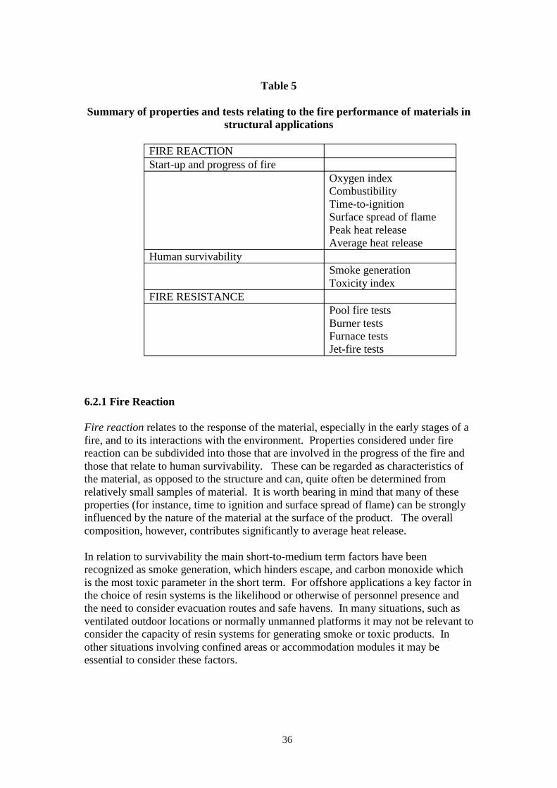
Table 5
Summary of properties and tests relating to the fire performance of materials in structural applications
FIRE REACTION Start-up and progress of fire
Oxygen index Combustibility Time-to-ignition Surface spread of flame Peak heat release Average heat release
Human survivability Smoke generation Toxicity index
FIRE RESISTANCE Pool fire tests Burner tests Furnace tests Jet-fire tests
6.2.1 Fire Reaction
Fire reaction relates to the response of the material, especially in the early stages of a fire, and to its interactions with the environment. Properties considered under fire reaction can be subdivided into those that are involved in the progress of the fire and those that relate to human survivability. These can be regarded as characteristics of the material, as opposed to the structure and can, quite often be determined from relatively small samples of material. It is worth bearing in mind that many of these properties (for instance, time to ignition and surface spread of flame) can be strongly influenced by the nature of the material at the surface of the product. The overall composition, however, contributes significantly to average heat release.
In relation to survivability the main short-to-medium term factors have been recognized as smoke generation, which hinders escape, and carbon monoxide which is the most toxic parameter in the short term. For offshore applications a key factor in the choice of resin systems is the likelihood or otherwise of personnel presence and the need to consider evacuation routes and safe havens. In many situations, such as ventilated outdoor locations or normally unmanned platforms it may not be relevant to consider the capacity of resin systems for generating smoke or toxic products. In other situations involving confined areas or accommodation modules it may be essential to consider these factors.
36

Typical data relating to the generation of smoke and toxic products are shown in Table 6. Here, it can be seen that the systems with very low smoke generation are phenolic and Modar (modified acrylic resin). These are probably the only systems that might be permitted in areas where personnel might be present with limited means of escape. The Modar system derives its low toxicity from the addition of alumina trihydrate additive. The other composite systems, polyester, vinyl ester and epoxy all have higher smoke and toxicity levels. It is worth noting that phenolic-based composites, which are generally well-regarded in terms of smoke emission, do not generally score highly in terms of toxicity because of CO generation.
The cone calorimeter (ISO 5660-1, 1993) requires relatively small 100mm x 100mm samples subjected to a known heat flux. It employs the ‘oxygen consumption’ principle to provide an indirect, but accurate measure of heat release the residual oxygen concentration in the exit gas stream. The technique enables several important fire reaction properties, including time to ignition and heat release, to be studied, as shown in Figures 25 and 26 (Gibson and Hume, 1995). Smoke and toxic product generation can also be measured. Figures 25 and 26 show that once again there is relatively little difference between the polyester, vinyl ester and epoxy composites, whereas the phenolic and Modar/ATH systems both shows clear benefits in terms of both time-to-ignition and heat release.
Tim
e to
igni
tion
[s]
1000
100
10
SyPhenolic stemi
s w tEpoxy h ATPolyester
H add
Vinyl ester
itives
10 100 Irradiance (kW/sq.m)
Figure 25. Log-log plot of cone calorimeter ignition time vs. irradiance for polyester, vinyl ester, epoxy and phenolic laminates, each with 50% wt. woven glass fibre reinforcement. Thickness: 3mm.
Also shown is the range of reported results for ATH-modified Modar and low toxicity polyester systems.
37

Peak
hea
t rel
ease
rate
[kW
/sq.
m]
600
500
400
300
200
100
0 0
50
[/
]
(a) (b)
VE
VE PE PE
Phenolic Phenolic
ATH syste
ms
ATH syste
ms
100
150
200
250
300
Ave
rage
hea
t rel
ease
rate
kW
sq.m Epoxy Epoxy
10 30 50 70 90 10 30 50 70 90 Irradiance [kW/sq.m] Irradiance [kW/sq.m]
Figure 26 (a) Peak heat release rate and (b) average heat release rate vs. irradiance for polyester (PE), vinyl ester (VE), epoxy and phenolic laminates, each with 50% wt. woven glass fibre reinforcement.
Thickness: 3mm.
Table 6
Comparative smoke and toxicity parameters for composite laminates based on different resin systems. (All samples are 50vol% glass/woven roving laminates,
except Modar, which contains 170 phr of alumina trihydrate and 40vol% of glass, and the low toxicity polyester with 300 phr of ATH).
Smoke - 3m Cube [BS 6853]
Ao (on) Ao (off)
Smoke Cone Calorimeter
[ISO 5660] Average at
50kW/m2 [m/s]
CO Cone
Calorimeter [ISO 5660]
Av. at 50kW/m2
[kg/s/m2]
Toxicity index
[NES 713]
Polyester 24.3 18.9 8.3 0.6 1.5 Vinyl ester 27 17.6 10.3 0.7 1.2 Epoxy 14.1 11.3 11.2 0.8 1.2 Modar 2.26 2.5 - - 1.2 Phenolic 0.36 0.41 0.8 1.0 1.0
38
6.2.2 Fire Resistance
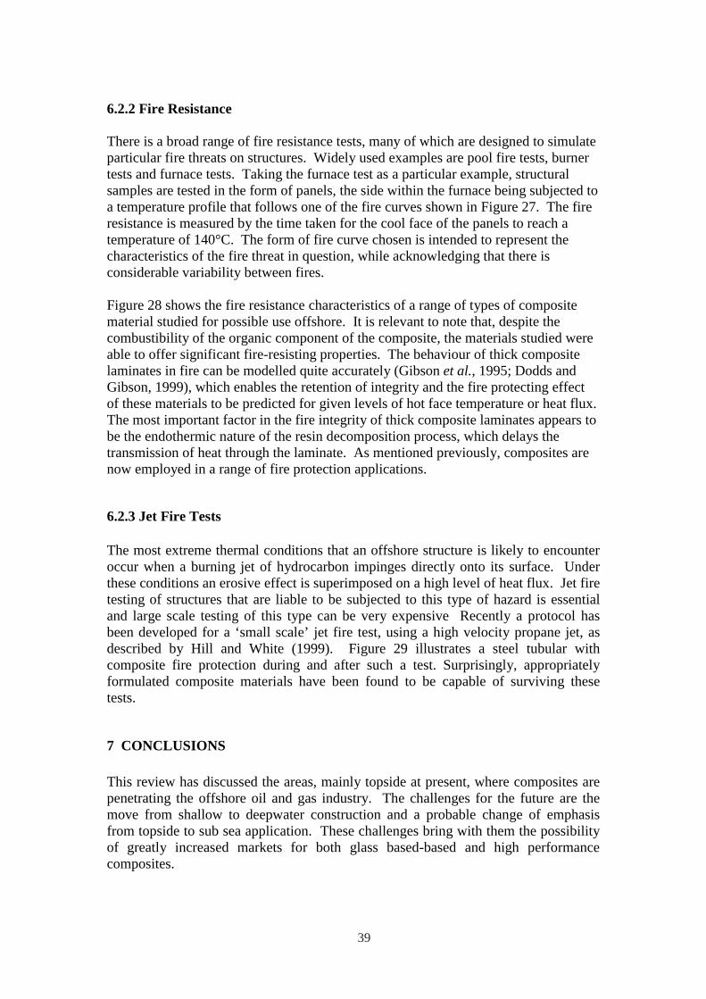
There is a broad range of fire resistance tests, many of which are designed to simulate particular fire threats on structures. Widely used examples are pool fire tests, burner tests and furnace tests. Taking the furnace test as a particular example, structural samples are tested in the form of panels, the side within the furnace being subjected to a temperature profile that follows one of the fire curves shown in Figure 27. The fire resistance is measured by the time taken for the cool face of the panels to reach a temperature of 140°C. The form of fire curve chosen is intended to represent the characteristics of the fire threat in question, while acknowledging that there is considerable variability between fires.
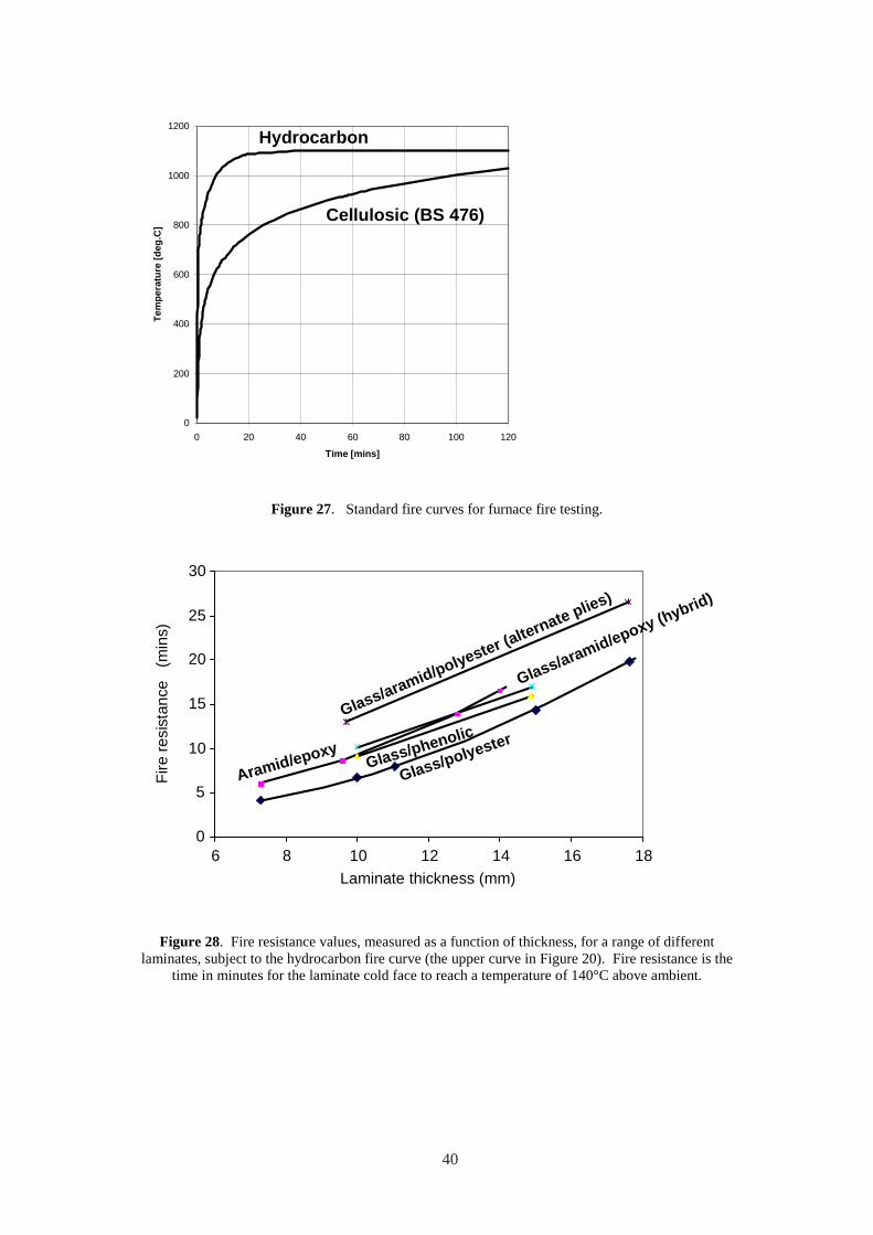
Figure 28 shows the fire resistance characteristics of a range of types of composite material studied for possible use offshore. It is relevant to note that, despite the combustibility of the organic component of the composite, the materials studied were able to offer significant fire-resisting properties. The behaviour of thick composite laminates in fire can be modelled quite accurately (Gibson et al., 1995; Dodds and Gibson, 1999), which enables the retention of integrity and the fire protecting effect of these materials to be predicted for given levels of hot face temperature or heat flux. The most important factor in the fire integrity of thick composite laminates appears to be the endothermic nature of the resin decomposition process, which delays the transmission of heat through the laminate. As mentioned previously, composites are now employed in a range of fire protection applications.
6.2.3 Jet Fire Tests
The most extreme thermal conditions that an offshore structure is likely to encounter occur when a burning jet of hydrocarbon impinges directly onto its surface. Under these conditions an erosive effect is superimposed on a high level of heat flux. Jet fire testing of structures that are liable to be subjected to this type of hazard is essential and large scale testing of this type can be very expensive Recently a protocol has been developed for a ‘small scale’ jet fire test, using a high velocity propane jet, as described by Hill and White (1999). Figure 29 illustrates a steel tubular with composite fire protection during and after such a test. Surprisingly, appropriately formulated composite materials have been found to be capable of surviving these tests.
7 CONCLUSIONS
This review has discussed the areas, mainly topside at present, where composites are penetrating the offshore oil and gas industry. The challenges for the future are the move from shallow to deepwater construction and a probable change of emphasis from topside to sub sea application. These challenges bring with them the possibility of greatly increased markets for both glass based-based and high performance composites.
39
Tem
pera
ture
[deg
.C]
1200
1000
800
600
400
200
0
H y dr oc a r b o n
Cel l ulos ic (BS 47 6 )
Fire
resi
stan
ce
(min
s)
0 20 40 60 80 100 120
Ti m e [m i n s]
Figure 27. Standard fire curves for furnace fire testing.
30
25
20
15
10
5
0 6 8 10 12 14 16 18
Laminate thickness (mm)
Glass/polyesterGlass/phenolic
Aramid/epoxy
Glass/aramid/polyester (alternate plies)
Glass/aramid/epoxy (hybrid)
Figure 28. Fire resistance values, measured as a function of thickness, for a range of different laminates, subject to the hydrocarbon fire curve (the upper curve in Figure 20). Fire resistance is the
time in minutes for the laminate cold face to reach a temperature of 140°C above ambient.
40
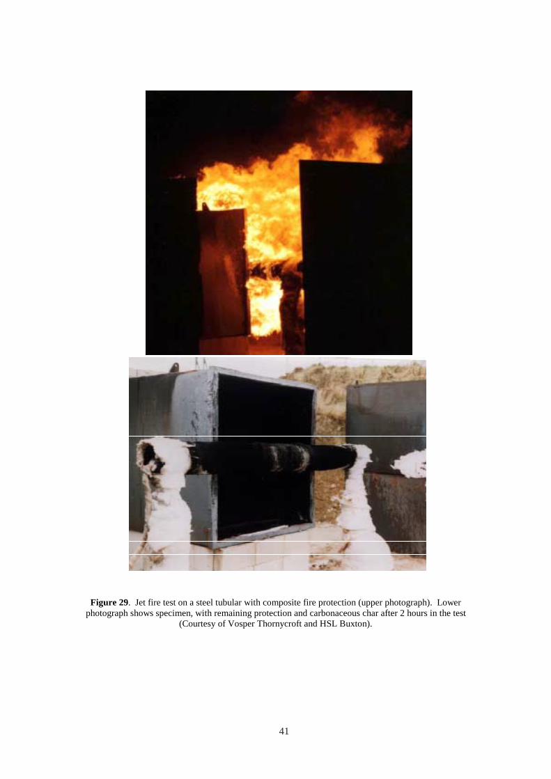
Figure 29. Jet fire test on a steel tubular with composite fire protection (upper photograph). Lower photograph shows specimen, with remaining protection and carbonaceous char after 2 hours in the test
(Courtesy of Vosper Thornycroft and HSL Buxton).
41

42
8. REFERENCES
AEA Technology, Guideline for the Application of Composite Repair Systems, 2001.
L. Anisdahl, D.T. Wang and R. Stokke, in Composite Materials for Offshore Operations-2 (CMOO-2)’, eds. S.S. Wang, J.G. Williams and K.H. Lo, American Bureau of Shipping, Houston TX 77060, 1999, ISBN 0-943870-01-1. pp261-274.
ARP, Final Report on The Cost-Effective Use of Fibre Reinforced Composites Offshore, Phase 4. 2000, Advanced Research Partnership, UMIST, P.O.Box 88, Sackville Street, Manchester M60 1QD
B. Asdal and A. Boye Hansen, in Composite Materials for Offshore Operations-2 (CMOO-2)’, eds. S.S. Wang, J.G. Williams and K.H. Lo, American Bureau of Shipping, Houston TX 77060, 1999, ISBN 0-943870-01-1. pp319-328.
ASME Boiler and Pressure Vessel Code, Section X: Fibre Reinforced Plastic Pressure Vessels, The American Society of Mechanical Engineers, 1992.
ASTM 2992-96e1, Standard Practice for Obtaining Hydrostatic or Pressure Design Basics for “Fiberglass” (Glass-Fiber-Reinforced Thermosetting-Resin) Pipe and Fittings.
D. Baldwin, N. Newhouse and K.H. Lo, in Composite Materials for Offshore Operations-2 (CMOO-2)’, eds. S.S. Wang, J.G. Williams and K.H. Lo, American Bureau of Shipping, Houston TX 77060, 1999, ISBN 0-943870-01-1. pp115128.
D. Baldwin, N. Newhouse and K.H. Lo, in Composite Materials for Offshore Operations-2 (CMOO-2)’, eds. S.S. Wang, J.G. Williams and K.H. Lo, American Bureau of Shipping, Houston TX 77060, 1999, ISBN 0-943870-01-1. pp275286.
F. Botros, J. Williams and E. Coyle, ‘Offshore Technology Conference’, OTC 8500, 1997.
A. Boye Hansen and B. Asdal, OTC8436, Offshore Technology Conference, Houston 5-8 May, 1997.
BS 4994: Design and Construction of Vessels and Tanks in Reinforced Plastics, British Standards Institution, London UK, 1987.
T. Carlson, Product data on pultruded phenolic gratings, Strongwell, 1999; also in proceedings of Composites in Fire Conference, ed. A.G. Gibson, University of Newcastle upon Tyne, 15-16 September 1999.
A.E. Churchman, J.M.C. Cadei and R. Shirandami, in Composite Materials for Offshore Operations-2 (CMOO-2)’, eds. S.S. Wang, J.G. Williams and K.H. Lo,
43
1994
American Bureau of Shipping, Houston TX 77060, 1999, ISBN 0-943870-01-1. pp447-460.
S Ciaraldi, J D Alkire and G Huntoon, Fiberglas Firewater Systems for Offshore Platforms, Paper OTC 6926, 23rd Annual Offshore Technology Conference, Houston TX, May 6-9 1991.
‘Composite Materials for Offshore Operations: Proceedings of the First International Workshop’, Houston TX 26-28th October, 1993. NIST Special Publication 887.
M.J. Cowling et al, Composites A, 2000.
J. Croquette, Potential Applications of Composites Offshore, Proc. Of Composite Materials in the Petroleum Industry, Institut Français du Pétrole, November 3-4,
DNV Joint Industry Project on FRP Design Guidelines, Det Norske Veritas AS, 2000.
A.T. Do, O. Beaudoin, P. Odru and F. Grosjean, in Composite Materials for Offshore Operations-2 (CMOO-2)’, eds. S.S. Wang, J.G. Williams and K.H. Lo, American Bureau of Shipping, Houston TX 77060, 1999, ISBN 0-943870-01-1. pp141-150.
N. Dodds and A.G. Gibson, in Composite Materials for Offshore Operations-2 (CMOO-2)’, eds. S.S. Wang, J.G. Williams and K.H. Lo, American Bureau of Shipping, Houston TX 77060, 1999, ISBN 0-943870-01-1. pp77-92.
Eurocode for Composite Materials, 1994.
F.J. Fischer, Revue de l’Institut Français du Pétrole, Jan-Feb. 1995, 50, 1.
F.J. Fischer and M.M. Salama, in Composite Materials for Offshore Operations-2 (CMOO-2)’, eds. S.S. Wang, J.G. Williams and K.H. Lo, American Bureau of Shipping, Houston TX 77060, 1999, ISBN 0-943870-01-1. pp33-50.
H. Fowler, 2nd North American Coiled Tubing Roundtable, Montgomery TX, 1-3 April 1997, Paper SPE 38414.
S.H. Fowler, M. Feechan and S.A. Berning, in Offshore Technology Conference, Houston TX, 4-7 May 1998, Paper OTC 8621.
R. Friedrich, in Composite Materials for Offshore Operations-2 (CMOO-2)’, eds. S.S. Wang, J.G. Williams and K.H. Lo, American Bureau of Shipping, Houston TX 77060, 1999, ISBN 0-943870-01-1. pp183-196.
S.R. Frost, in Composite Materials for Offshore Operations-2 (CMOO-2)’, eds. S.S. Wang, J.G. Williams and K.H. Lo, American Bureau of Shipping, Houston TX 77060, 1999, ISBN 0-943870-01-1. pp341-360.
44
A G Gibson, Composites in Offshore Structures, Chapter 3 of Composite Materials in Maritime Structures, Volume 2, eds R A Shenoi and J F Wellicome, Cambridge Ocean Technology Series, 1993
A.G. Gibson, editor, Proceedings of Offshore and Marine Composites, University of Newcastle upon Tyne, 5-6 April, 2000.
A.G. Gibson, editor, Proceedings of Piping and Infrastructure, University of Newcastle upon Tyne, 10-11 April 2001, ISBN 0-9540459-0-4.
A.G. Gibson, editor, Proceedings of Composites in Fire Conferences, University of Newcastle upon Tyne, 15-16 September 1999 and 12-13 September 2001, ISBN 0-9540459-1-2.
A.G. Gibson, J.T. Evans, G. Kotsikos, S.D. Speake and J.M. Hale, Plastics, Rubber and Composites, 2000, 29, 10, pp 533-538.
A.G. Gibson and J. Hume, Plastics, Rubber and Composites Processing and Applications, 1995, 23, 3, pp175-185.
A.G. Gibson, Y. Wu, H W Chandler, J.A.D. Wilcox and P. Bettess, Revue de l’Institut Français du Pétrole, Jan-Feb. 1995, 50, 1.
J.M. Hale, B.A. Shaw, S.D. Speake and A.G. Gibson, Plastics, Rubber and Composites, 2000, 29, 10, pp 539-548.
P.S. Hill and G.C. White, in Composite Materials for Offshore Operations-2 (CMOO-2)’, eds. S.S. Wang, J.G. Williams and K.H. Lo, American Bureau of Shipping, Houston TX 77060, 1999, ISBN 0-943870-01-1. pp623-634.
C.J. Houghton, in Composite Materials for Offshore Operations-2 (CMOO-2)’, eds. S.S. Wang, J.G. Williams and K.H. Lo, American Bureau of Shipping, Houston TX 77060, 1999, ISBN 0-943870-01-1. pp17-32.
Institut Français du Pétrole, Proceedings of ‘Composite Materials in the Petroleum Industry’, November 3-4, 1994
ISO 5660-1 Cone calorimeter testing standard, 1993.
ISO/DIS 14692-1, Petroleum and natural gas industries - Glass reinforced (GRP) piping – Parts 1-4, 2000.
ISO 109281: 1997, Plastics pipe systems – glass reinforced thermosetting plastic (GRP) pipes and fittings – methods of regression analysis and their use, 1997.
D.B. Johnson, D.D. Baldwin and J.R. Long, in Proceedings of the Offshore Technology Conference, Houston TX, 3-6 May 1999. Paper OTC 11008.
45
M. Kalman and J. Belcher, in Composite Materials for Offshore Operations-2 (CMOO-2)’, eds. S.S. Wang, J.G. Williams and K.H. Lo, American Bureau of Shipping, Houston TX 77060, 1999, ISBN 0-943870-01-1. pp151-165.
O. Konur and F.L. Matthews, Composites, 20, 4, July 1989, pp317-328.
G. Kotsikos, S.D. Speake, J.M. Hale, J.T. Evans and A.G. Gibson, in proceedings of ECCM9 - Composites from Fundamentals to Exploitation, Institute of Materials, IoM Communications, 4-7 June 2000.
A.R. Mableson, K.R. Dunn, N. Dodds and A.G. Gibson, Plastics, Rubber and Composites, 2000, 29, 10, pp 558-565.
P. Medlicott and A. Panayotti, in Composite Materials for Offshore Operations-2 (CMOO-2)’, eds. S.S. Wang, J.G. Williams and K.H. Lo, American Bureau of Shipping, Houston TX 77060, 1999, ISBN 0-943870-01-1. pp207-226.
B. Melve et al., in Composite Materials for Offshore Operations-2 (CMOO-2)’, eds. S.S. Wang, J.G. Williams and K.H. Lo, American Bureau of Shipping, Houston TX 77060, 1999, ISBN 0-943870-01-1. pp17-32.
J. Murali, M.M. Salama, O. Jahnsen and T. Meland, in Composite Materials for Offshore Operations-2 (CMOO-2)’, eds. S.S. Wang, J.G. Williams and K.H. Lo, American Bureau of Shipping, Houston TX 77060, 1999, ISBN 0-943870-01-1. pp129-149.
M Orpin, Alderley Materials, UK, product data; and in proceedings of Composites in Fire Conference, ed. A.G. Gibson, University of Newcastle upon Tyne, 15-16 September 1999.
P. Quigley, H. Fowler, S. Nolet and S. Berning, in Composite Materials for Offshore Operations-2 (CMOO-2)’, eds. S.S. Wang, J.G. Williams and K.H. Lo, American Bureau of Shipping, Houston TX 77060, 1999, ISBN 0-943870-01-1. pp207-226.
M.M. Salama, Revue de l’Institut Français du Pétrole, Jan-Feb. 1995, 50, 1.
G.D. Sims, UK Polymer Composites Sector- Competitive Analysis and Foresight Study, NPL 2001 (www.npl.co.uk/cog/ and www.netcomposites.com).
H.G. Scholte, in Composite Materials in Maritime Structures, eds R A Shenoi and J F Wellicome, Cambridge Ocean Technology Series, 1993
C.P. Sparks et al., Revue de l’Institut Français du Pétrole, Jan-Feb. 1995, 50.
W.D. Stringfellow (Ed.), ‘Fiberglas Pipe Handbook’, Fiberglas Pipe Institute, 355 Lexington Ave., New York 10017, 1992.
United Kingdom Offshore Operators Association (UKOOA), ‘Specification and Recommended Practice for the Use of GRP Piping Offshore’, March 1994.
46

S.S. Wang, J.G. Williams and K.H. Lo (eds.), Composite Materials for Offshore Operations-2 (CMOO-2)’, American Bureau of Shipping, Houston TX 77060, 1999, ISBN 0-943870-01-1.
S.S. Wang, J.G. Williams and K.H. Lo (eds.), Proceedings of Composite Materials for Offshore Operations-3 (CMOO-3)’, Houston TX 77060, 2000.
D A Witcher, Strongwell USA product data, and in Composite Materials for Offshore Operations-2 (CMOO-2)’, eds. S.S. Wang, J.G. Williams and K.H. Lo, American Bureau of Shipping, Houston TX 77060, 1999, ISBN 0-943870-01-1. pp229-240.
47

48
PART B: SUMMARY OF THE JOINT INDUSTRY - INDUSTRY PROGRAMME ON
THE COST EFFECTIVE USE OF FIBRE REINFORCED COMPOSITES OFFSHORE
Professor A.G. Gibson, Programme Director of Research
Centre for Composite Materials Engineering,
University of Newcastle Upon Tyne
and
D.A. Spagni, Programme Manager
Advanced Research Partnership
49
ACKNOWLEDGEMENT
The financial contribution of the following companies and organisations to the Composites Offshore programme is gratefully acknowledged.
AGIP/TIEN AGIP (UK) Amerada Hess Ameron Fiberglass Pipe Division Ameron International Amoco (UK) Amoco Research Balmoral Group Bow Valley Petroleum (UK) Ltd BP Exploration BP Research Brasoil (UK) Ltd British Gas Ciba Geigy Conoco (UK) Conoco Research Cray Valley Products Dow Deutschland Inc. Department of Trade and Industry/ Department of Energy DERA Det Norske Veritas Elf UK Elf Aquitaine Group
Enichem SpA Engineering and Physical Sciences Research Council Electricite de France Exxon Production Research Health and Safety Executive Hunting Engineering Ltd Kerr McGee Oil (UK) Ltd MaTSU Maunsell Structural Plastics Ministry of Defence (PE) Mobil Research & Development Co. Mobil North Sea Ltd MTD Ltd Norsk Hydro Odebrecht Oil and Gas Offshore Supplies Office Petrobras Phillips Petroleum Co. UK Ltd Shell Expro Statoil Total Oil Marine Vosper Thornycroft UK Ltd VSEL
Without the help and encouragement of individuals within the sponsoring companies this research would not have taken place.
In addition, special further thanks are due to Shell SIEP and BP for making available information from internal reports on the Composites Offshore programme. This information forms the backbone of the summary given here.
50
CONTENTS
1. INTRODUCTION 55
2. PHASE 1 (1988-1990) 59
2.1. CP01 Impact behaviour of pultruded gratings 59
2.2. CP02 Composite cylinders subjected to axial compression and external pressure 60
2.3. CP03 Design of Tee-intersections for composite pipes 60
2.4. CP04 Impact response of thick composite laminates and sandwich structures 61
2.5. CP05 Failure of composite pipes under local loading 62
2.6. CP07 Fire resistant sandwich panels for offshore structures 63
2.7. CP08 Impact behaviour of fire resistant twin skined laminates and panels 63
2.8. CP09 Lightweight, fire resistant, FRP/steel composite structures for topsides 64
2.9. CP10 Assessment of fire performance of fibre reinforced composites for possible
use offshore 65
2.10. CP12 The Behaviour of Composites in Production Fluids 66
2.11. CP19 Hygrothermal properties of fibre-reinforced composites 67
3. PHASE 2 (1991-1993) 69
3.1. CP201 Bonded structural components for offshore structures 69
3.2. CP202 Design and performance of panel elements for energy absorption and
resistance to penetration and impact 70
3.3. CP204 The response of sandwich panels to blast loading 71
3.4. CP205/222 Fire resistant sandwich panels for offshore structures and composites
pipework with improved fire resistance 72
3.5. CP241 Durability of composite components in marine environments 72
3.6. CP244 Design of composite structures for mechanical and fire performance 73
3.7. CP271 Non-destructive testing on fibre reinforced plastics in the offshore
industry 74
3.8. CP272 Regulatory and Classification Requirements for the Application ofComposite Materials for Pipework Offshore 75
3.9. CP275 General principles and guidance for the application of glass reinforced
composites offshore 75
3.10. CP299 Damage Tolerance of Composite Pipes to Local Impact Loads. 76
51
4. PHASE 3 (1994-1997) 79
4.1. CP301/302 Models for the fire behaviour of fibre-reinforced composite
components 79
4.2. CP303 Burst strength and non-destructive evaluation of composite pipes and
pipe couplings with defects 80
4.3. CP304 Structural integrity of bonded connections between polymer composite
components in marine applications 82
4.4. CP305 The response of sandwich panels to blast loading 83
4.5. CP306 Impact and residual properties of composite laminates subjected to
secondary blast damage 84
4.6. CP307 Impact strength of sandwich panels: modelling and residual Strength 85
4.7. CP309 Performance of FRP at elevated temperatures and pressures 87
4.8. CP310 Wear and erosion of GRP pipework 88
4.9. CP311 Impingement erosion behaviour of fibre reinforced polymer composites
in marine environments 90
4.10. CP312 Non-destructive techniques for the evaluations of composites in offshore
structures 91
5. PHASE 4 (1998-2001) 95
5.1. CP402 Method of assessing and predicting long term strength of filament wound
pipes 95
5.2. CP404 Failure envelopes for composite tubulars in liquid environments at high
temperatures 98
5.3. CP411 Fatigue in offshore components in liquid environments 102
5.4. CP412 Prediction of the behaviour of polymer composite systems in fire
conditions 104
5.5. CP418 Structural integrity of bonded connections in composite components
subjected to fatigue 108
5.6. CP421 Impact damage assessment for GRP composite pipes 111
5.7. CP423 Long term damage tolerance of glass fibre reinforced composites 113
5.8. CP451/CP452/CP453: Design of composites topsides 115
5.9. DNV Recommended Standard Composite Components 120
Appendix 1 The Programme 122
Appendix 2 Programme Team Leaders and Principal Investigators 126
Appendix 3 Membership of the Programme Steering Committee 130
52
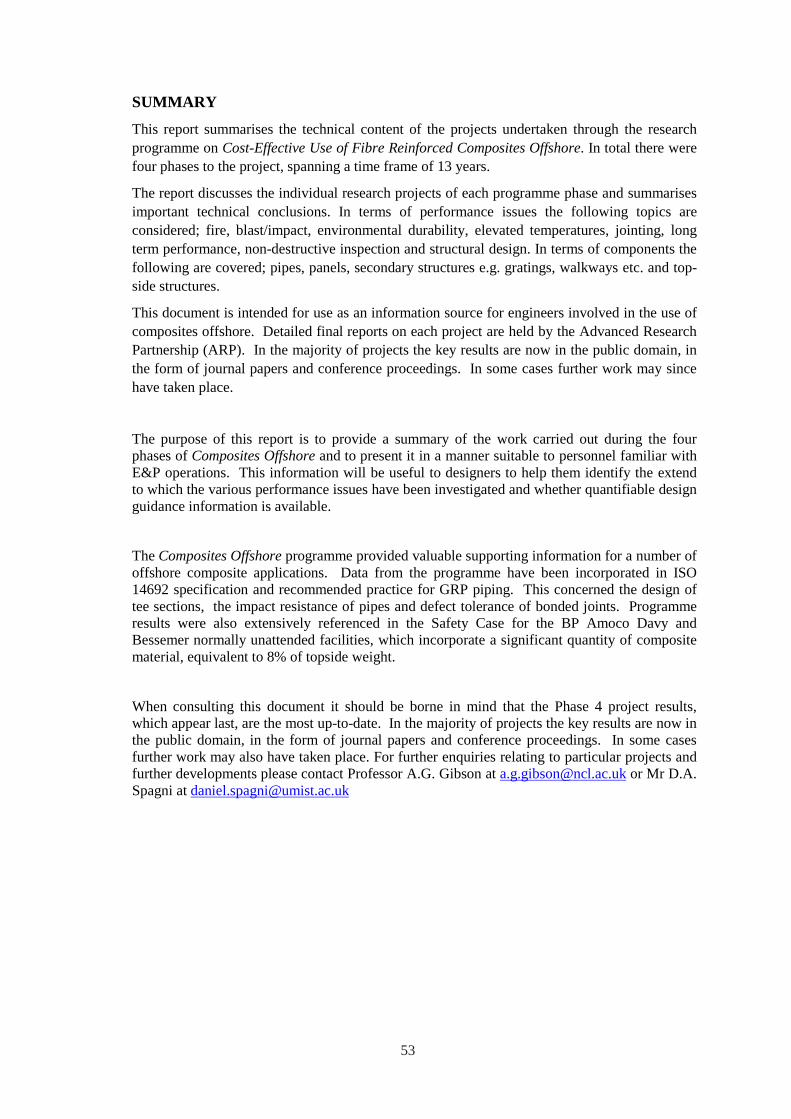
SUMMARY
This report summarises the technical content of the projects undertaken through the research programme on Cost-Effective Use of Fibre Reinforced Composites Offshore. In total there were four phases to the project, spanning a time frame of 13 years.
The report discusses the individual research projects of each programme phase and summarises important technical conclusions. In terms of performance issues the following topics are considered; fire, blast/impact, environmental durability, elevated temperatures, jointing, long term performance, non-destructive inspection and structural design. In terms of components the following are covered; pipes, panels, secondary structures e.g. gratings, walkways etc. and topside structures.
This document is intended for use as an information source for engineers involved in the use of composites offshore. Detailed final reports on each project are held by the Advanced Research Partnership (ARP). In the majority of projects the key results are now in the public domain, in the form of journal papers and conference proceedings. In some cases further work may since have taken place.
The purpose of this report is to provide a summary of the work carried out during the four phases of Composites Offshore and to present it in a manner suitable to personnel familiar with E&P operations. This information will be useful to designers to help them identify the extend to which the various performance issues have been investigated and whether quantifiable design guidance information is available.
The Composites Offshore programme provided valuable supporting information for a number of offshore composite applications. Data from the programme have been incorporated in ISO 14692 specification and recommended practice for GRP piping. This concerned the design of tee sections, the impact resistance of pipes and defect tolerance of bonded joints. Programme results were also extensively referenced in the Safety Case for the BP Amoco Davy and Bessemer normally unattended facilities, which incorporate a significant quantity of composite material, equivalent to 8% of topside weight.
When consulting this document it should be borne in mind that the Phase 4 project results, which appear last, are the most up-to-date. In the majority of projects the key results are now in the public domain, in the form of journal papers and conference proceedings. In some cases further work may also have taken place. For further enquiries relating to particular projects and further developments please contact Professor A.G. Gibson at [email protected] or Mr D.A. Spagni at [email protected]
53

54
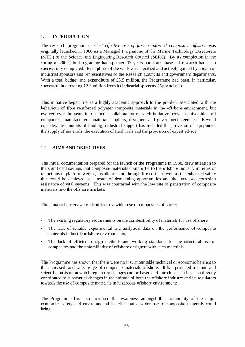
1. INTRODUCTION
The research programme, Cost effective use of fibre reinforced composites offshore was originally launched in 1988 as a Managed Programme of the Marine Technology Directorate (MTD) of the Science and Engineering Research Council (SERC). By its completion in the spring of 2000, the Programme had spanned 13 years and four phases of research had been successfully completed. Each phase of the work was specified and actively guided by a team of industrial sponsors and representatives of the Research Councils and government departments. With a total budget and expenditure of £5.9 million, the Programme had been, in particular, successful in attracting £2.6 million from its industrial sponsors (Appendix 1).
This initiative began life as a highly academic approach to the problem associated with the behaviour of fibre reinforced polymer composite materials in the offshore environment, but evolved over the years into a model collaboration research initiative between universities, oil companies, manufacturers, material suppliers, designers and government agencies. Beyond considerable amounts of funding, industrial support has included the provision of equipment, the supply of materials, the execution of field trials and the provision of expert advice.
1.2 AIMS AND OBJECTIVES
The initial documentation prepared for the launch of the Programme in 1988, drew attention to the significant savings that composite materials could offer to the offshore industry in terms of reductions in platform weight, installation and through life costs, as well as the enhanced safety that could be achieved as a result of demanning opportunities and the increased corrosion resistance of vital systems. This was contrasted with the low rate of penetration of composite materials into the offshore markets.
Three major barriers were identified to a wider use of composites offshore:
• The existing regulatory requirements on the combustibility of materials for use offshore;
• The lack of reliable experimental and analytical data on the performance of composite materials in hostile offshore environments,
• The lack of efficient design methods and working standards for the structural use of composites and the unfamiliarity of offshore designers with such materials.
The Programme has shown that there were no insurmountable technical or economic barriers to the increased, and safe, usage of composite materials offshore. It has provided a sound and scientific basis upon which regulatory changes can be based and introduced. It has also directly contributed to substantial changes in the attitude of both the offshore industry and its regulators towards the use of composite materials in hazardous offshore environments.
The Programme has also increased the awareness amongst this community of the major economic, safety and environmental benefits that a wider use of composite materials could bring.
55
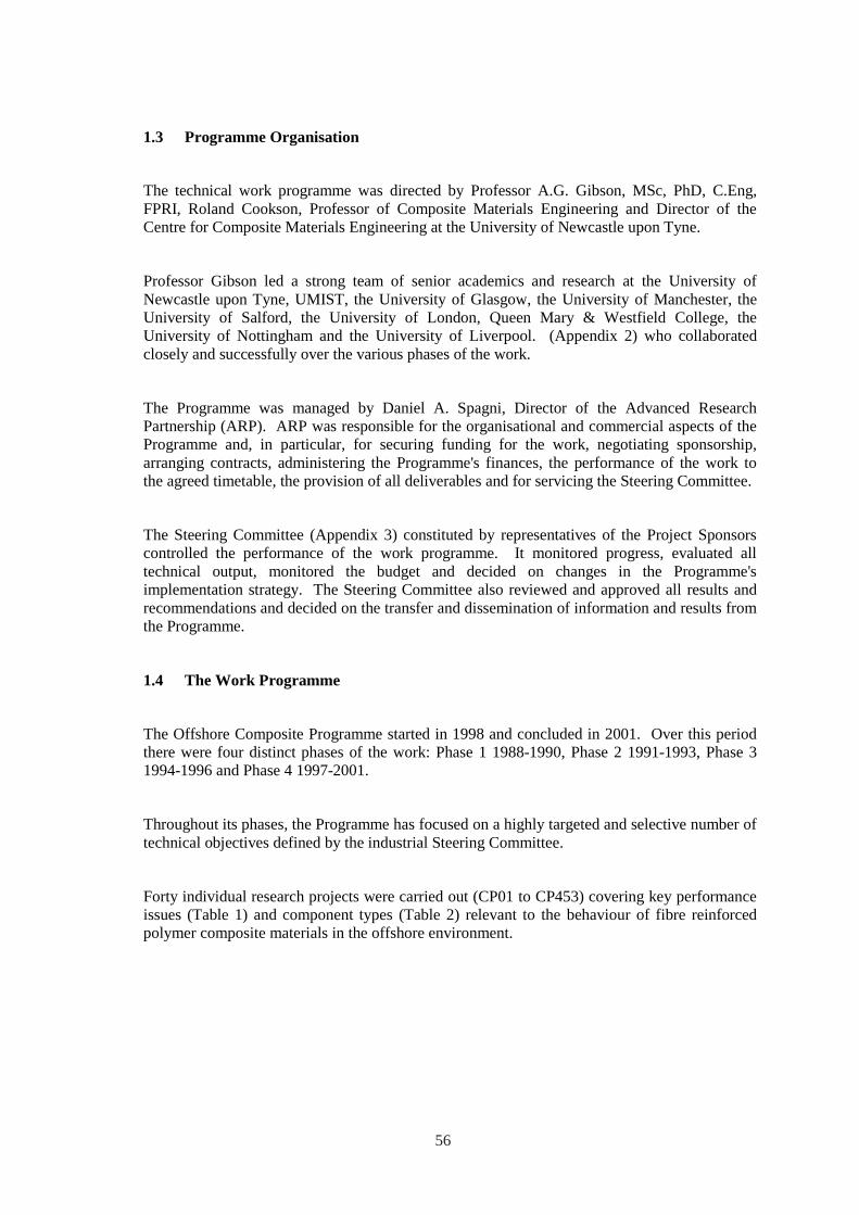
1.3 Programme Organisation
The technical work programme was directed by Professor A.G. Gibson, MSc, PhD, C.Eng, FPRI, Roland Cookson, Professor of Composite Materials Engineering and Director of the Centre for Composite Materials Engineering at the University of Newcastle upon Tyne.
Professor Gibson led a strong team of senior academics and research at the University of Newcastle upon Tyne, UMIST, the University of Glasgow, the University of Manchester, the University of Salford, the University of London, Queen Mary & Westfield College, the University of Nottingham and the University of Liverpool. (Appendix 2) who collaborated closely and successfully over the various phases of the work.
The Programme was managed by Daniel A. Spagni, Director of the Advanced Research Partnership (ARP). ARP was responsible for the organisational and commercial aspects of the Programme and, in particular, for securing funding for the work, negotiating sponsorship, arranging contracts, administering the Programme's finances, the performance of the work to the agreed timetable, the provision of all deliverables and for servicing the Steering Committee.
The Steering Committee (Appendix 3) constituted by representatives of the Project Sponsors controlled the performance of the work programme. It monitored progress, evaluated all technical output, monitored the budget and decided on changes in the Programme's implementation strategy. The Steering Committee also reviewed and approved all results and recommendations and decided on the transfer and dissemination of information and results from the Programme.
1.4 The Work Programme
The Offshore Composite Programme started in 1998 and concluded in 2001. Over this period there were four distinct phases of the work: Phase 1 1988-1990, Phase 2 1991-1993, Phase 3 1994-1996 and Phase 4 1997-2001.
Throughout its phases, the Programme has focused on a highly targeted and selective number of technical objectives defined by the industrial Steering Committee.
Forty individual research projects were carried out (CP01 to CP453) covering key performance issues (Table 1) and component types (Table 2) relevant to the behaviour of fibre reinforced polymer composite materials in the offshore environment.
56
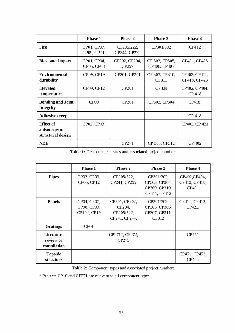
Phase 1 Phase 2 Phase 3 Phase 4
Fire CP01, CP07, CP09, CP 10
CP205/222, CP244, CP272
CP301/302 CP412
Blast and Impact CP01, CP04, CP202, CP204, CP 303, CP305, CP421, CP423 CP05, CP08 CP299 CP306, CP307
Environmental CP09, CP19 CP201, CP241 CP 303, CP310, CP402, CP411, durability CP311 CP418, CP423
Elevated temperature
CP09, CP12 CP201 CP309 CP402, CP404, CP 418
Bonding and Joint Integrity
CP09 CP201 CP303, CP304 CP418,
Adhesive creep CP 418
Effect of CP02, CP03, CP402, CP 421 anisotropy on structural design
NDE CP271 CP 303, CP312 CP 402
Table 1: Performance issues and associated project numbers
Phase 1 Phase 2 Phase 3 Phase 4
Pipes CP02, CP03, CP05, CP12
CP205/222, CP241, CP299
CP301/302, CP303, CP304,
CP402,CP404, CP412, CP418,
CP309, CP310, CP421 CP311, CP312
Panels CP04, CP07, CP08, CP09,
CP201, CP202, CP204,
CP301/302, CP305, CP306,
CP411, CP412, CP423,
CP10*, CP19 CP205/222, CP241, CP244,
CP307, CP311, CP312
Gratings CP01
Literature CP271*, CP272, CP451 review or CP275
compilation
Topside CP451, CP452, structure CP453
Table 2: Component types and associated project numbers
* Projects CP10 and CP271 are relevant to all component types.
57

58

2. PHASE 1 (1988-1990)
2.1 CP01 Impact behaviour of pultruded gratings
2.1.1 Introduction
This work describes a comprehensive programme of 3 point static loading and impact testing carried out on three pultruded GRP grating systems supplied by Fiberforce Ltd. The work investigated the following:
1. The effect of load distribution across the beams.
2. Failure mode.
3. Critical energy to cause onset of failure.
4. The effect of span.
5. Residual strength.
6. The effect of fire.
2.1.2 Experimental details
The gratings were made from assemblies of pultruded T (Pedwalk 38mm and Duradek 50 mm), and I-beam (Duradek - I, 38 mm) sections connected by transversely running composite dowels. The polyester and vinyl ester resin matrices contained appropriate fire retardents and fillers.
2.1.3 Results
The results of testing showed that the static strength underestimates impact performance and that the load distribution has practical implications on performance. The transverse dowels are very effective at sharing load and the grating panel retains significant strength even when individual beams have been taken past the critical energy of failure. The critical energy for the panel may be of the order of 1000 J for 1000 mm span and under such circumstances beams exhibit visible damage on the top compression surface. However where all beams are loaded simultaneously failure is catastrophic the critical energy may be as low as 250 J (5 beams loaded, 1000 mm span).
The Duradek T section beams underwent substantial lateral buckling prior to failure which may be a benefit to indicate the onset of overload although the buckling must contribute to a reduction in the gratings load carrying capability.
The gratings exhibited no significant loss of strength when not visibly damaged after exposure to fire such that the maximum temperature experienced by the grating was less than 300 deg C. Even visibly charred grating had the potential to retain substantial strength.
2.1.4 Significance
The work provides important performance information with regard to the safe use of GRP gratings offshore and in particular it addresses possible concerns about the post impact strength capability of GRP gratings. The work suggests that static strength can be used to provide a conservative estimate of impact performance. However the results relate to pultruded sections and caution should be applied when considering moulded gratings.
The work demonstrated that visibly charred GRP grating that appears to be essentially intact after exposure to fire can support the weight of evacuating personnel after it has been exposed to heat radiation from a fire.
59
2.2 CP02 Composite cylinders subjected to axial compression and external pressure
2.2.1 Introduction
This work describes an experimental and theoretical investigation into the buckling and material strength of filament wound (55 degree) GRP cylinders when subject to external pressure and axial compression loading.
2.2.2 Experimental details
The test cylinders were 500 to 2000 mm in length, with 100 and 200 mm internal diameter and 5 to 6.5 mm wall thickness.
2.2.3 Modelling and results
A finite element computer code was written to calculate the theoretical bifurcation buckling and first ply to failure of the pipe subject to different combinations of loading conditions. The results are summarised as follows:
• Very good agreement was achieved between theory and practice.
• The majority of the experimental results of critical loads lay within 0.9 to 1.03 of the theoretical prediction.
• For the geometries tested the buckling mode of failure is dominant for external pressure : axial compression ratios greater than 0.25.
2.2.4 Significance
While the characteristics of GRP cylinders subject to internal pressure and tensile loading is reasonably well covered in the literature little information is available for the compressive stress conditions investigated in this work. Such conditions are pertinent for example to downhole tubing/casing and risers. The work validates the use of appropriate theoretical methods to predict external collapse loads of composite tubular elements, the testing of which may be difficult or expensive to carry out in practice.
2.3 CP03 Design of Tee-intersections for composite pipes
2.3.1 Introduction
This work investigated the mechanical performance of commercially available designs of GRP tee-pieces subject to internal pressure and external loads typical of a piping layout, eg in-plane and out of plane bending.
2.3.2 Experimental details
Partial filament wound components were supplied from Wavin and Ameron. Hand-lay samples components were supplied by Resinform and PDE. The components were extensively strain gauged both on the inside and outside surfaces and tested under pressure and flexure conditions. Most testing was designed to limit maximum strains to less than 0.2% but some tests were continued to failure. For each load condition strain concentration factors were determined as defined in BS 7159.
60

2.3.3 Modelling and results
The hand laminated components were modelled using finite element computer code to estimate stresses. The results are summarised as follows:
• Under pressure loading the hand laminated specimens failed by delamination. The filament wound components failed in the region of the adhesive socket joint.
• Apart from one hand laminated specimen all the components had an acceptable failure pressure to design pressure ratio. The strain concentration factor was generally in accordance with theory and of the order of 2.
• Under flexure the strain concentrations were generally less than 1. Theoretical modelling did not match the results but this may be attributed to the difficulty of accurately modelling the geometry and material detail.
• All the specimens exhibited a degree of shell bending, which would produce transverse shear and interlaminar stresses. However under flexure all components were relatively rigid and ovalisation effects were negligible. Hence in flexibility analysis the junction could be considered a rigid connection.
• All four types of tee could safely be used in offshore piping although each could benefit from improvement.
2.3.4 Significance
This work provided information about flexibility and stress concentration factors previously missing from BS 7159.
2.4 CP04 Impact response of thick composite laminates and sandwich structures
2.4.1 Introduction
This work provides comprehensive initial investigation into the impact response of single skin laminates and sandwich structures. The basis of the theoretical modelling is described in detail.
2.4.2 Experimental details
Quasi-static and low speed impact tests were carried out on 300 mm square panels supported on either a rigid base (for indentation tests) or a 200 mm square section aperture for 3 point bending. Two indentor shapes were used for the tests, hemisphere (20 to 100 mm diameter) and flat ended circular (20 and 35 mm diameter) profiles.
Laminate skins from 0.7 to 9.0 mm thick were made from either woven roving or chopped strand mat using either polyester or phenolic resin matrices. A few experiments were also carried out using a carbon/glass hybrid and a kevlar 49 cloth. A range of core materials of different densities and thickness were investigated. The materials included PVC, polyurethane and phenolic foam. Crushing experiments were carried out to characterise the core properties.
2.4.3 Results
Over the range of parameters tested the main mode of deformation was local indentation rather than global bending and shearing. Hence skin thickness (and reinforcement weight) was the major panel parameter determining panel strength and energy absorption. Indentor shape and size are important determining failure mode and energy to failure. The flat indentor produced a shear plug penetration failure while the hemisphere failure was due to a tensile bending. The failure load of the flat indentor was higher than that of the hemisphere. In low speed impact
61
tests the load and energy to first failure and complete perforation of the panel were higher than under quasi-static loading.
The choice of resin type (polyester or phenolic) had little influence on performance. Note that this result is true for normal resins but experience in the design of armour shows that resin properties and particularly the fibre / resin interface may play an important role. Over the range of parameters tested, the core properties had significantly less influence on panel performance than the skin. An exception is the case of thin cores and large indentor radii, which could result in core densification before skin fracture, or alternatively where the core has very high compressive strength and stiffness.
Conventional theory for bending of whole sandwich panels overestimated the strength and stiffness. But plate bending theory applied to a single skin, ignoring the core, gave a reasonable first approximation to the actual behaviour of single skins loaded by a flat punch and a conservative estimate of sandwich panel performance up to failure of the top skin.
2.4.4 Significance
The work provides data for estimating the low velocity impact performance of single skin laminates and sandwich panels made from composite materials. For design purposes quasi-static data can be used to provide a conservative guide to impact performance.
2.5 CP05 Failure of composite pipes under local loading
2.5.1 Introduction
This work describes an investigation into the behaviour of GRP pipe subject to local quasi-static and impact loading (<45 m/s). The work investigated the sequence and mechanics of failure and the influence of internal contents, i.e. empty or filled/pressurised. The effect of including a liner or using a tougher resin was also investigated and comparisons were made with the behaviour of steel pipe subject to similar loading.
2.5.2 Experimental details
The internal diameter of the filament wound pipe supplied by Wavin (now Future Pipe Industries) was 100 mm and testing was carried out on two wall thicknesses, 4.3 and 8.0 mm. The indentor had a hemispherical shaped nose with a diameter of 12.7 mm. The pipe was mounted on a rigid base plate representative of the most severe piping support conditions.
2.5.3. Results
The sequence of failure begins with resin whitening followed by resin cracking. The pipe then undergoes structural collapse and associated delamination. Perforation may or may not occur depending on wall thickness. On removal of the load the damaged pipe recovers back to its original shape. Initial damage to the pipe under quasi-static loading occurred at energies less than 3 J. Under impact loading resin whitening was observed at energies less than 10 J. Under quasi-static loading penetration occurred at just under 300 J for both wall thicknesses. Delamination was shown to be a very efficient energy absorption mechanism. The equivalent penetration energy for 3.25 mm thick steel was 250 J. Under impact loading the square shaped delamination area was found to be directly proportional to impact energy. The energy to perforation was approximately twice the quasi-static energy, 640 J. The perforation hole was 1/4 the punch diameter. The presence of water media inside the pipe had the effect of stiffening the wall and producing more localised damage. This substantially reduced the impact delamination area and energy for perforation.
62
The residual weepage or absolute strength of the pipe was reduced even at low impact energies (<20 J). Pipes could not hold water at impact energies greater than 240 J. The short term failure pressure of the pipe was inversely proportional to the impact energy, i.e. there was controlled leakage from the impact site. Over the medium term (24 hours), weepage could be detected from impact sites of 20 J upwards. The use of a tougher resin did not substantially enhance performance. The use of a liner did prevent weepage at low to moderate impact energies.
2.5.4 Significance
This work provides valuable performance data about the impact sensitivity of low pressure GRP piping systems.
2.6 CP07 Fire resistant sandwich panels for offshore structures
2.6.1 Introduction
The objective of the work was to develop fire resistant panels of lighter construction than existing products.
2.6.2 Experimental details
A low cost computer-controlled furnace was developed, which enabled laminate specimens to be subjected to a prescribed temperature-time curve.
Tests were carried out to evaluate the performance of commercial non-structural core materials including polystyrene, polyurethane and mineral wool. Similar tests were carried out to assess the surface protection offered by a number of commercial materials, including vermiculite, phenolic foam, mineral fibre and calcium silicate. A number of formulations based on sodium silicate, vermiculite, perliote, ball clay and latex were also investigated.
2.6.3 Significance
The main value of the work is that it provided a basis for developing fire testing expertise of value in Phase 2, 3 and 4 and provided fire resistance information of panel core materials such as polystyrene foam, phenolic foam, mineral wool and vermiculite.
2.7 CP08 Impact behaviour of fire resistant twin skined laminates and panels
2.7.1 Introduction
This work investigated the impact and fire resistant properties of twin skinned sandwich panels.
2.7.2 Impact
Two types of panel construction were considered, the first with a cellular honeycomb core, 13 mm and 26 mm thick, the second using a resin impregnated non woven polyester fibre with microspheres (coremat), 10 mm thick. In both cases the facing skins were made using 2 plies of woven roving and epoxy or polyester resin. The panels were subject to quasi-static and impact testing while supported on clamped but free to pull-in supports with a span of 500 mm. The indentor tup profile was a 50 mm diameter hemisphere. The effect of other geometry shapes on the failure mechanism was also investigated. A finite element analysis was also carried out to provide a basis to assess the influence of different panel support boundary conditions.
The data was presented as graphs to show the relationship of failure mode with tup mass, tup velocity and core thickness. From the point of view of measured forces and energies the Coremat panel had superior impact properties (penetration 887 J against 294 J for the 13 mm honeycomb core). However taking account the mass per unit area of the panels then the performance of the panels was comparable.
63
2.7.3 Fire
The work considered:
The design aspects of a twin skined sandwich panel to achieve a 0.5 bar blast and H120 fire rating.
The means of controlling the delamination of glass reinforced phenolic panels, believed to be produced by the conversion of water entrapped within the resin at manufacture to steam when the panel is exposed to fire.
In the case of the former the design of the panel was based around glass reinforced 18 ply polyester skins (approx. 9 mm thick) structurally connected by an array of 50 mm square section box glass polyester pultrusions. The panel was constructed to enable the performance of end grain balsa and a ceramic blanket (Kaowool) non-structural core materials to be separately assessed. The effect of including a silica fabric within the skin was also evaluated. The panel survived the H120 test as a whole although areas of weakness were identified.
The means of controlling delamination of the phenolic panel were based on methods of stitching several layers of reinforcing plies together and providing easier paths for steam to escape. Neither method was entirely successful.
2.7.4 Significance
The work showed that the design of a composite panel to meet a blast and H120 rating is feasible and that several manufacturing permutations are possible (see also CP 09). The work also highlighted the difficulty of controlling delamination of room temperature cured glass phenolic panels when exposed to severe fire, which degrades the structural integrity of the panel.
2.8 CP09 Lightweight, fire resistant, FRP/steel composite structures for topsides
2.8.1 Introduction
The aim of the work was to produces recommendations for a practical adhesively bonded hybrid construction of GRP panel and steel or GRP stiffeners suitable for a single or double skin applications on topsides. The issues of concern were strength, impact, fire and long term durability. The work focussed on material selection and performance of a fire and blast wall. The design restraints assumed were, 0.3 bar overpressure, 2.5 m support span, H60 or H120 fire rating.
2.8.2 Experimental details
The following parameters were examined:
Material combinations within the panel, i.e. load bearing, stiffening, insulation;
Mechanical and thermal properties of adhesives;
Bonded joint fabrication aspects, e.g. surface preparation, use of peel plies , use of fillet radii,and adhesive mixing;
Effect of immersion in salt water of bonded joint;
Small scale fire, i.e. fire reaction properties of various material combinations;
Static mechanical testing of panel to simulated blast loading;
Fire resistance performance of assembled panel;
Numerical modelling (FE) of the panel and adhesive joint.
64
2.8.3 Results
Araldite 2004 was selected (from six) as the preferred adhesive because it gave the best compromise of strength / impact properties at ambient and elevated temperatures. Despite its relatively low Tg, the adhesive still retained significant creep resistance at 150 deg C.
A GRP/GRP adhesive joint was found to be significantly less strong than a steel / steel joint. Use of peel plies, fillet radii and automatic mixing/dispensing did improve joint quality. Exposure of adhesive double strap (steel/steel) joints to salt water immersion showed only 12% reduction in shear strength after 18 months. There was no evidence of corrosion on the steel interface.
The use of intumescent paints to provide insulation protection and reduce heat release was effective for the first 5 minutes after which the paint charred and disintegrated. Silica fabrics were found to undergo significant shrinkage during fire. It was noted that glass polyester laminates have similar fire resistance performance to plywood of the same thickness.
2.8.4 Significance
Many of the observations provide useful background information for assessing the performance of GRP fire and blast panels. The appendix contains fire reaction data of different material combinations.
2.9 CP10 Assessment of fire performance of fibre reinforced composites for possible use offshore
2.9.1 Introduction
This project was fully funded by the then Department of Energy. The aims were:
To provide fire performance on a range of composite components including single laminates, sandwich / hybrid panels, and open grillage structures.
To establish baseline performance data and enhance the fundamental understanding of reaction and failure mechanisms of composite materials under fire conditions.
To provide information to assist the interpretation of fire performance data obtained using standard fire tests with the requirements of real offshore fire scenarios.
2.9.2 Experimental details
The baseline resins were polyester, vinyl ester, epoxy and phenolic. Most testing was carried out using woven roving laminates but some early testing was carried out with chopped strand mat. Laminates ranged from 6 to 42 ply, approximately 3 to 14 mm thick. Hybrids included honeycomb and intumescent coated panels. The effect of two fire retardents aluminium trihydrate (ATH) and Ceepree were also investigated.
The cone calorimeter was used to determine time to ignition, peak and average heat release rate, carbon monoxide and smoke levels as a function of irradiance. Other standard tests were used to measure spread of flame, accumulation of smoke and toxicity products and fire resistance.
2.9.3 Results
The tested composites were all resistant to spread of fire when exposed to a small domestic heat source conditions, e.g. burning wastepaper basket. However all were capable of contributing significant heat release when exposed to a large heat input typical of a hydrocarbon fire. Thick
65
wall laminates were found to have significantly lower peak and average heat release rates compared to thin laminates.
The rate of smoke and toxic evolution is very much a function of the overall fire spread conditions e.g. ventilation and irradiation conditions rather than a direct property of the material although it should be noted that phenolic produces substantially less smoke that the other resins. The baseline resins have little toxic potency, the main harmful element being carbon monoxide. Phenolic resins have significantly improved fire reaction properties compared to the other three resins.
Furnace tests based on current standards were found to underestimate the severity of a hydrocarbon pool fire because the test procedure effectively subtracts the heat release contribution of the composite from the input heat flux. The presence of water within the phenolic resin resulted in the creation of steam pockets and explosive delamination during furnace testing.
There was low heat conduction along composite grillage structures during the pool fire testing. The use of fire retardents provided no added protection to grillage structures exposed to conditions where sufficient thermal feedback was allowed to build up to cause a flashover. In these circumstances the resin was quickly burn off leaving bare glass fibre.
2.9.4 Significance
The work provides valuable background information of the fire behaviour of composites exposed to different heat flux radiance levels.
2.10 CP12 The Behaviour of Composites in Production Fluids
2.10.1 Introduction
This work investigated the effect of production fluids on high pressure GRP piping and includes a useful literature survey.
2.10.2 Experimental details
Anhydride epoxy 97 mm internal diameter, 8 to 9 mm thick GRP tubes were supplied by ABB of Sweden. These were filled with either Gulfaks ‘A’ crude oil or brine. Both media were topped with a 90/10 mixture of methane and carbon dioxide at a pressure ranging between 90 and 130 bar. The test temperature was 80°C. The original intention had been to expose the tubes for a period up to 18 months but due to an oversight in the design of the end closure (which resulted in premature failure of the end closure), the test period had to be restricted to 6 months.
On completion of the exposure period, the tubes were subject to an internal pressure burst test such that loading was confined to just the hoop stress. The test samples were also strain gauged. Diametral compression tests were carried out on ring specimens cut from the tube. Visual, SEM and Dynamic Mechanical Thermal Analysis (DMTA) examinations were also performed.
2.10.3 Results
No reduction in burst strength or mechanical properties could be detected after 6 months exposure to either environment. Visual examination showed a “whitening” of the resin on the surface exposed to brine after 6 months. This intensified with increasing pressure. This was believed to be due to hydrolytic degradation of the surface resin, which exposed the glass fibres.
66
The glass transition temperature of the sample exposed to brine reduced from 135°C to 115°C indicating that brine was having a plasticising effect on the resin. Samples exposed to oil showed evidence of local penetration at voids in the surface but were not affected to the same extent as those exposed to brine.
2.10.4 Significance
While the work demonstrates the ability of glass/epoxy tubulars to contain high pressure production fluids at 80°C in the short and medium term, it confirmed previously identified concerns about the suitability of anhydride cured epoxies for this service.
2.11 CP19 Hygrothermal properties of fibre-reinforced composites
2.11.1 Introduction
This work investigated the mechanism and rate of water ingress into GRP laminates. It was recognised that absorption rates through the edge and face surfaces of the laminate would be different but no attempt was made to seal the cut edges because of concerns about the effectiveness of such treatment. Instead additional experiments were carried out using laminates of different edge to face surface ratios to enable the diffusivity through the face surfaces alone to be deduced by calculation.
2.11.2 Experimental
The laminates were made from two reinforcements, chopped strand mat and woven rovings, and three resin types, polyester, vinyl ester and phenolic. The 25 x 25 x (3 - 6) mm test laminates were immersed in water for periods up to 400 days at temperatures of 5, 25, 40, 70 deg C and pressures of 1, 25, 50 and 75 bar. However before testing the laminates were vacuum dried until they showed no further weight loss.
2.11.3 Results
The water ingress was Fickian at all temperatures and pressures but many of the specimens immersed in water at 5 oC and 25 oC had not become saturated after 400 days. The polyester specimens exhibited weight loss at 70 oC due to dissolving of certain resin constituents into the water. For the specimens that did saturate the moisture content was approximately 8 - 15% for phenolic, 1 - 2% for polyester and 1 - 2 % for vinyl ester depending on fibre volume fraction. The high absorption of phenolics is to be expected because of the nature of the resin, which has a high proportion of microvoids.
The diffusivity increased with increasing temperature in accordance with an Arrhenius law. The diffusivities were significantly dependent on pressure and in general increased linearly with increasing pressure. This is opposite to the behaviour of pure polymers and it was speculated that the observed pressure effects were due to water being forced into micropores of the composite and particularly along the fibre resin interface.
The rates of water ingress, characterised by diffusivity, were larger for the edges of the specimens than the faces. The degree of diffusivity anisotropy varied with the type of polymer but no systematic dependence on the type of glass reinforcement was found.
2.11.4 Significance
The work provides information for predicting the amount of water absorbed in a component at any given time after immersion.
67

68

3. PHASE 2 (1991-1993)
3.1 CP201 Bonded structural components for offshore structures
3.1.1 Introduction
This work focused on two main activities:
1. Investigation and understanding of adhesive durability and thermal performance
2. Investigation of behaviour characteristics of steel/GRP and GRP/GRP adhesively bonded joints used in single skin and double skin panel (sandwich) fabrications in static, fatigue and impact loading. Reinforcing webs were made from GRP pultrusions.
A parametric study of sandwich panel design parameters and a review of 6 candidate adhesives including representatives of two part epoxies, acrylics and polyurethanes were also carried out.
3.1.2 Experimental and modelling details
Joints were modelled using finite element analysis. Modelling and testing was carried out to:
characterise the mechanical properties of selected adhesives and a GRP pultruded profile and to determine the effect of temperature on the mechanical and creep properties of the joint (up to 150 C) and to determine the optimum design of butt strap joint.
A database was initiated of the durability properties of the selected adhesives, which investigated the effect of spew fillets, and surface pre-treatment of the adherend. Testing was done to distinguish the effects of moisture ingress on the bulk properties of the adhesive from that on the adhesive/adherend interface. Consideration was given to determining the sensitivity of joint performance to handling and mixing procedures.
Tests were also carried out to determine the effect of fatigue and impact on performance of stiffened panel when loaded in flexure.
3.1.3 Results
Where the predominant loading is shear and bending, the structural strength of the joint was found to be limited by the poor interlaminar strength of the polyester pultrusions rather than the performance of the adhesive.
Manual mixing of two part adhesive was found to be adequate and manufacturers’ recommendations can be exceeded in many circumstances. COSHH requirements for adhesive bonding are not particularly onerous in well ventilated conditions. Surface preparation of both steel and GRP laminates need not be more sophisticated than abrasion. However the use of silane primers on steel had superior performance than corrosion inhibitor. Of the adhesives reviewed, Redux 420 gave the best all round properties for bonding GRP.
The interface zone between the adhesive and adherend appears to be the more significant factor causing failure rather than changes in the bulk adhesive after samples have been exposed to accelerated ageing. It was suggested that a durability allowance of 20% should be included in the design calculations.
Maximum butt joint strength was found to be achieved by a design using steel tapered strapping plates which gives 70% of the strength of the parent material in tension.
69
3.1.4 Significance
This work provided useful information about the design and application of adhesive joints.
3.2 CP202 Design and performance of panel elements for energy absorption and resistance to penetration and impact
3.2.1 Introduction
This work describes a detailed investigation carried out into the parameters which most influence the energy absorption and resistance to penetration properties of panels subject to impact, dropped object or projectile damage. Three types of panel were studied:
1. Single skin laminate (2 - 16 mm thick)
2. Single skin laminate resting on a core foundation mounted on a steel base.
3. Sandwich panel. (skins 2 - 7 mm thick, core up to 25 mm thick)
The second configuration was used to assist the understanding of the influence of the core and factors, which produce local deformation.
3.2.2 Experimental details
The GRP skins were made from two weights of woven glass reinforcement, 800 g/m2 and 1500 g/m2 and polyester resin. Two types of core were used, Divinycell (130 and 400 kg/m3) and Vermiculux (475 kg/m3). Other test parameters included:
• spans of 300 mm and 900 mm
• clamped boundary conditions
• flat, hemispherical and conical indentors up to 50 mm diameter
• projectile velocities up to 120 m/s
3.2.3 Results
At low velocities the laminate and sandwich behaviour was similar and conservative to that observed in quasi-static tests. The flat indentor gave the highest loads and energies to first penetration. However for flat indentors the energy to first penetration also corresponded to total penetration. Failure of the panel was usually characterised by local deformation. Only for the highest density core could a global bending failure mode of the sandwich panel be induced.
The size of delamination area was linearly proportional to the magnitude of absorbed energy and the energy absorbed could be correlated to the total weight of reinforcement in the skins.
The laminates made up of the lighter weight reinforcement (800 g/m2) absorbed more energy than the laminates of equivalent thickness made up of the heavier 1500 g/m2 cloth.
3.2.4 Significance
This work provides a basis for designing and assessing the ability of composite panels to resist penetration by dropped objects and projectiles of moderate energy. The report provides detailed information and comment about:
• Failure modes and conditions which produce localised and global deformations
70

• Size of visible damage in relation to energy absorbed.
• Relationship between indentor shape, panel thickness and energy to first penetration and total energy absorbed.
• Methods for predicting the energy absorption of panels and optimising panel design.
3.3 CP204 The response of sandwich panels to blast loading
3.3.1 Introduction
This work describes work carried out to gain a better understanding of the response of composite panels to blast loading. The following activities were carried out:
1. An experimental study using small, 250 x 250 mm, and medium size, 750 x 750 mm panels.
2. An analytical theoretical study using Mindlin’s plate analysis.
3. A finite element analysis, which could investigate the requirements to model composite damage and boundary conditions.
The report begins with a brief outline of the nature of gas explosions and the difficulties of modelling the response of panels to blast, taking account of failure mechanisms, physical/mechanical properties of the material, geometry and constraints. A literature survey of the modelling of sandwich panels and response of panels to blast is also given.
3.3.2 Experimental details
Three methods of generating the required shape of dynamic pressure pulse necessary to simulate full-scale blast were investigated. Air blast and through water explosive shock techniques were used in the small-scale rig. A contained gas explosion mixture was used in the medium scale rig. The scaled pressure pulses corresponded to 0.2 - 0.5 bar overpressure and 1 to 1.5 millisecond rise time of a full scale blast. Both single skin laminates and double skin sandwich panels were tested.
3.3.3 Results and modelling details
Failure of the panel was generally related to shear at the clamped edges. Failure of the core was by compression and debonding depending on choice of core material. Full details of the experimental results including maximum recorded strains are given in the report.
Both the Mindlin and FE analysis techniques gave accurate predictions of response within the linear regions provided realistic input data was used. Further development is required to handle non-linear behaviour.
3.3.4 Significance
There is no validated design procedure for modelling exposure of composite blast panels to blast. This work could provide the basis of deriving a simplified design procedure, which was investigated in Phase 3.
71
3.4 CP205/222 Fire resistant sandwich panels for offshore structures and composites pipework with improved fire resistance
3.4.1 Introduction
The aim of this work was to:
1. Construct a furnace based modest fire testing facility capable of reproducing the DOE/NPD fire curve.
2. Characterise the characteristics of a small-scale jet fire facility based on the same burner as the main furnace.
3. Carry out fire testing of core materials, panels and pipes with the aim of characterising fire performance and deriving a predictive tool.
The development of the furnace facility was largely successful and the report discusses the procedures that have to be taken to simulate the very rapid rise temperature required in the first 30 seconds of the hydrocarbon fire curve. Work on developing a small-scale jet fire facility was suspended after the very great difficulties of reproducing the conditions of a full size jet fire became apparent.
3.4.2 Experimental details and results
A range of core materials for panels were tested, concentrating on an in-house material, made from perlite, high alumina cement and water. Other materials tested included phenolic foam, polyphosphosine foam , a ceramic foam and a sodium silicate panel supplied by BP. Various permutations of reinforced polyester skin lay-ups were evaluated including the use of resin impregnated ceramic wool and heavily filled retarded resin. Both gave significantly improved fire performance over conventional GRP skins.
The fire testing of pipes was limited to simulating the dry start up condition of a firewater deluge system. Tests were carried out on non-fire protected epoxy and phenolic pipes. Tests on epoxy pipes coated with a ceramic fibre blanket for protection are also reported.
The development of a model for the fire performance of panels and pipes in a fire described and attention drawn to the influence the of entrapped water.
3.4.3 Significance
The work provides data useful for evaluating the fire performance of composite structures.
3.5 CP241 Durability of composite components in marine environments
3.5.1 Introduction
The purpose of this work was to provide quantified information of the effect of the following environmental conditions on the mechanical and physical properties of GRP.
• immersed conditions
• exposure to splash zone
• erosion effects
• marine fouling
72

• H2S from sulphate reducing bacteria
The effect of pressure and temperature is also considered and jet impingement erosion tests were carried out on some laminates.
3.5.2 Experimental details
The samples were taken from:
• chopped strand reinforced isophthalic polyester, aromatic amine cured epoxy and vinyl ester resin laminates;
• woven roving reinforced vinyl ester resin laminates;
• filament wound glass reinforced aromatic amine cured epoxy and vinyl ester resin pipes;
• Unreinforced cast polyester and epoxy resins.
Additional studies were carried out with laminates made from acrylic and phenolic resins.
Mechanical tests were carried out to determine of the effect of water absorption on flexure,interlaminar shear and impact properties.
3.5.3 Results
Reductions in strength of GRP in seawater was found to be modest, ranging from 15 % for epoxies to 30% for polyester. Of potential greater concern was the significant reduction in impact strength. Epoxy laminates performed best, polyester worst, and vinyl ester performed better than polyester. In normal seawater the degradation in flexure and impact properties was found to cease after a few months. The presence of marine fouling had no effect on mechanical properties and is easier to remove than from metal components.
Deterioration of properties is not simply related to water uptake. Degradation phenomena were found to occur internally with no surface manifestations. Reductions in the molecular weight of epoxy and polyester resins were observed in the surface regions of the laminate with time, which correlated with reductions in mechanical properties. The presence of H2S had no effect on degradation rate.
3.5.4 Significance
The results of this work confirm that long term degradation of GRP is unlikely to be an issue for GRP structures exposed to the normal marine environment. A possible area of concern not highlighted before is the reduction in impact properties.
3.6 CP244 Design of composite structures for mechanical and fire performance
3.6.1 Introduction
The aim of this work was to investigate and model the mechanical and fire performance of FRP panels of different constructions.
3.6.2 Experimental
The investigation concentrated on thick skin panels sandwich panels where 9mm skins were separated by internal structural elements. The internal space was filled with a refractory fibrous
73
material to enhance fire resistance. The panels were tested in 3 and 4 point bending (approx. 2 m span). The types of failure mode were investigated and quantified.
Fire tests were carried out on 12 panels comprising glass reinforced polyester or phenolic single skin laminates and sandwich panels of different configurations. The sandwich panels had skins made with either polyester or modar resin. Both solid structural cores (made from Vermiculux or Dragonite) and cores made from internal structural elements and Kaowool were evaluated. The single skin laminates were instrumented so that the temperature time history through the thickness could be recorded.
3.6.3 Results and modelling details
The panels were modelled using a commercially available finite element code. The flexure tests showed there was good agreement between theory and practice at less than medium to medium/high loads where the properties can be considered reasonably linear. At high loads, predictions of performance were influenced by non-linear material and boundary condition effects and debonding between the internal elements and the skin. In these particular tests the corrugated internal element panel performed better than the ‘U’ internal element panel.
The fire tests provided an insight into how various materials behave in a fire. For example it was noted that the polyester resin starts to degrade at a slightly lower temperature than phenolic. The Dragonite and Vermiculux cores remained intact after the outer skin had burnt away. All the sandwich panels achieved H60 with the exception of one of the internal element panels where the Kaowool had been inadequately inserted in place.
The fire modelling represents a significant advance in the understanding of the state of the art. The sensitivity to parameters that influence fire performance over the duration of the fire was investigated and the decomposition and ablation characteristics of the composite laminate skins were successfully modelled using a 1-D finite difference procedure. The model took account of conductive heat transfer, resin decomposition and the passage of gaseous decomposition products through the laminate. Comparison of theory and experiment is provided for polyester and phenolic laminates.
3.6.4 Significance
The project provided useful data from which to judge the ability of modelling techniques to analyse the mechanical and fire performance behaviour of panels. The work formed a basis to enable the modelling of more complex 3-D structures.
3.7 CP271 Non-destructive testing on fibre reinforced plastics in the offshore industry
3.7.1 Introduction
This document contains a literature survey of NDT techniques of possible use for assessing the quality and integrity of composites during both the processing stage and as a fabricated component. The following NDE techniques were reviewed:
Radiography Thermography Dielectric Ultrasonics
White Light Microwave Electric Acoustic Emission
Coherent Light Eddy Current Spectroscopy Vibration
74

3.7.2 Results
Most of the above NDE techniques are generally only suitable for laboratory use and collectively they are capable or deriving substantial information about the composite, for example quality of fibre lay-up, state of cure, moisture content and position of defects. However, while NDT is capable of detecting many of the defects of interest, for example delamination and voids, little progress has been made with respect to the detection of poor bonds of concern in adhesive joints. The most promising techniques for monitoring structural integrity were identified to be:
• acoustic emission;
• ultrasonics;
• thermography;
• coin tapping;
• radiography.
3.7.3 Significance
This document provides a useful background of NDE techniques available and sense of their likely applicability in the field. Practical experience of NDE techniques for offshore use appears to be limited to acoustic emission, ultrasonics and radiography.
3.8 CP272 Regulatory and Classification Requirements for the Application of Composite Materials for Pipework Offshore
3.8.1 Introduction
The original scope for this work was overtaken as a consequence of UKOOA activities to develop engineering documentation for GRP piping offshore. A revised scope of work was drawn up in liaison with the UKOOA FRP Workgroup. The key activity became the development of a database of fire testing of GRP piping.
3.8.2 Results
A PC based database was produced which currently contained 108 records from 14 data sources. The data sources are taken from the open literature, Ameron and Wavin manufacturer’s information and some operator test data.
3.8.3 Significance
The database provided a mechanism to enable a statistical evaluation of GRP piping fire performance with the aim of minimising the need for further fire testing.
3.9 CP275 General principles and guidance for the application of glass reinforced composites offshore
3.9.1 Introduction
The purpose of this project was to summarise the key findings of a large body of research from this programme and elsewhere on composites in a manner that designers and offshore engineers will readily assemble and be able to use and apply in the field.
75
3.9.2 Contents of report
The contents of the document, which contains many significant omissions, e.g. impact properties of gratings, is made up of the following sections:
1. General Characteristics and Properties.
This gives a good overview of material properties and manufacturing processes andcomments on general design calculation methods and sources of information.
2. Fire Performance
This describes different fire test methods and presents typical fire performance results. The mechanics of thermal degradation is discussed together with fire modelling methods.
3. Impact Performance
Results are presented of a range of materials and properties for panels and pipe sections. Failure mechanisms and the production of failure maps are discussed.
4. Adhesive Bonding
This includes a review of different adhesive types and gives typical properties. Joint design, surface and adhesive preparation and durability are discussed and comment is made of the effect of impact and elevated temperature.
5. Durability in a Marine Environment
The effect of water absorption on flexural, shear and impact properties is discussed. The behaviour is sensitive to resin type with most degradation of properties occurring early within the test period. Comment is made of the effect of biological growth and the effect of temperatures above 50 deg C.
3.9.3 Significance
The document provides a valuable compilation of performance information relevant to offshore applications of composites.
3.10 CP299 Damage Tolerance of Composite Pipes to Local Impact Loads.
3.10.1 Introduction
This work provides a comprehensive set of test data of the material deformation and failure characteristics of GRP pipe subject to localised mechanical damage such as impact. The work was a continuation of the Phase 1 study, which showed the susceptibility of GRP pipes to local damage and the very large differences in energies between those which could cause weepage damage and those resulting in perforation of the pipe.
3.10.2 Experimental details
The following parameters were investigated:
• Indentor shape, i.e. flat circular, hemispherical, conical and wedge up to 25 mm diameter.
• Mass, velocity, force and energy
• Construction type, i.e. filament wound and chopped strand matt.
• The use of internal polymer linings.
The sample to be tested was mounted on a rigid flat surface. The 100 mm ID filament wound pipes were of two wall thickness, 4.3 mm and 8 mm. The samples were subjected to quasi-static
76
loading, and impact tests from a pneumatic launcher. Some samples were pressurised prior to impact.
3.10.3 Results
As would be expected the pipe offered least resistance to perforation when loaded by 15 degree conical, 15 degree wedge and flat circular shaped indentors, the penetration failure mode being piercing or shear type failure. The filament wound pipes loaded by hemispherical indentors absorbed the largest amount of energy. The corresponding energies for a 15 degree conical and 12.7 mm 1 kg hemispherical indentors were 36 J and 670 J respectively. There was a critical indentor diameter above which no perforation occurred. Scaling was found to be not straightforward, and not just dependent on mass, and wall thickness had an influence on the failure mode. There was a pronounced velocity effect on the energy absorption mechanism and the pipes could absorb significantly more energy under dynamic than quasi-static loading. In all cases the pipe retrieved its essential shape after the load was removed.
For unlined pipes the residual failure strength, either weepage or burst, was found to quickly reduce to about 0.2 to 0.4 the original burst strength after impact. The effect of a plastic liner was to delay weepage failure such that is occurred at much higher energies.
For the filament wound pipes the impact site was characterised by a square shaped delamination, the area being proportional to the absorbed energy. The initial failure load was dependent on indentor diameter and the onset of initial delamination was detected for impact energies as low as 5 J. The presence of water inside the pipe had the effect of reducing both the size of the delamination area and the ballistic limit, i.e. reduce the effect of bending to absorb energy and increase shear. It was observed there could be a degree of self repair and reduction in weepage when the pipe was subsequently re-pressurised.
The chopped strand matt lined pipes had very much lower strength, stiffnesses and energy absorption capabilities compared to the filament wound pipes. Also, they showed no sign of delamination and impact damage was very localised.
The ability to detect impact damage by ultrasonic and SPATE techniques was investigated but only qualitative conclusions could be drawn.
3.10.4 Significance
The work provides useful data by which to assess the likely impact performance and failure mode in a risk assessment analysis.
77

78
4 PHASE 3 (1994-1997)
4.1 CP301/302 Models for the fire behaviour of fibre-reinforced composite components
4.1.1 Introduction
The aims of this project were to produce experimentally validated computer models to describe the ablation and heat transfer behaviour of a wide range of composite materials subjected to hydrocarbon fires. This required:
1. The development of modelling tools to aid the design of panel and pipe components required to function in a fire.
2. Fire testing of panels and both dry and water filled pipes to be carried out with the aim of characterising fire performance and validating the predictive tool.
4.1.2 Modelling and panel test
The computer model takes account of three main effects: heat conduction, volatile convection within the laminate and endothermic resin decomposition. The most important of these is shown to be the endothermic decomposition term which represents the heat absorbed by the decomposition of the resin into volatile products. For this reason laminates with higher resin content, e.g. chopped strand mat, often give better fire insulation properties than laminates containing more glass, e.g. woven roving. However once the resin is consumed the insulation properties rapidly decay and the cold face temperature rises sharply. The model can be used to determine the proportion of unburnt resin left as a function of time, which provides a guide to the residual strength of a structure. A full range of hot face boundary conditions may be applied, including defined temperature profiles (such as the hydrocarbon fire curve) or heat fluxes. The rear face boundary conditions may include convection to air or water or conduction to steel or other structural materials. If required the endothermic contribution from vaporisation of entrapped water can also be included in the model.
The analysis procedures available include finite difference models for linear and radial heat flow and finite element models for more complex situations. The performance of the model, for a range of different composite systems and geometries, was verified against thermal data obtained from the furnace fire tests. The range of materials included glass and aramid fibres and chopped strand and woven roving reinforcement. The predominant matrix materials were polyester, epoxy, and phenolic resin. The accuracy of the model predictions of cold face temperature during hydrocarbon curve fire tests on glass fibre woven roving reinforced polyester panels was estimated as within +/- 11.4 % for panels of thickness in the range of 5 mm to 11 mm, the error reducing as the panel thickness increases further. The model is less accurate for laminates less than 5 mm in thickness, probably because of the increased effects of erosion and thermal loads on the structural integrity of the laminate.
4.1.3 Pipe Testing
Dry fire tests were carried out on 4” Ameron 2000M unprotected pipes with an average wall thickness of 5.4 mm. The time for the inside wall temperature to reach 200 oC in a hydrocarbon fire test was 1.7 minutes. In addition three unprotected 3” diameter experimental phenolic pipes were tested under hydrocarbon fire with average thicknesses of 5.6 mm, 7.7 mm and 9.5 mm respectively. The corresponding times before the inside temperature to reach 200 oC were 1.86,
79
2.75 and 3.5 minutes respectively. In both cases a good correlation between computational and experimental results was obtained which validated the model under dry conditions. Further testing was carried out which provided data about how to improve the fire resistance of dry pipes.
Tests of water filled pipe over an extended period of time were carried out such that a 1 m length of 50 or 100 mm diameter Ameron 2000M pipe inclined at 10 degrees to the horizontal was exposed to hydrocarbon fire conditions. The tests showed the ease by which steam could be produced in an unpressurised system. It was found that a 5 minute stagnant start was acceptable for a 50 mm diameter pipe and that this could be extended to 10 minutes for a 100 mm diameter pipe. In all cases the onset of flow (4 mm/s in a 100 mm pipe) quickly reduced the temperature and steady state conditions (between 50 oC and 100 oC) were reached after less than 20 minutes. Beyond that stage further degradation of the pipes was thought unlikely to occur and accordingly each test was normally run for a period off 30 minutes. The pipe was subsequently pressure tested and sustained an internal pressure of 16 bar with no leakage over a period of 3 minutes. The testing also showed that low flow rates could be tolerated and the pipe survived with a flow velocity of 3 mm/s in the 50 mm pipe, although steam started to form under these conditions.
4.1.4 Significance
A validated model was developed which can predict the rear face temperatures of composite panels and pipes exposed to user-defined fire loads. The work represents a significant start to the development of suitable modelling techniques that can be usefully employed in the design of composite structures and piping.
4.2 CP303 Burst strength and non-destructive evaluation of composite pipes and pipe couplings with defects
4.2.1 Introduction
GRP piping is susceptible to impact damage that can produce weepage through the pipe wall at relatively low energy levels. The concern was that penetration of seawater into the damaged area could result in escalation of the damage, leading to premature catastrophic failure of the pipe before repairs can be made. There is also concern about the possible effect of defects and exposure to seawater on the long term properties of adhesive bonded joints. This project sought to address both these issues. A further objective was to examine the burst strength of bonded composite pipe joints, with and without defects and to determine whether the defects introduced could be observed, again using ultrasonic NDE.
The report contains a simple procedure for taking account the flexible support normally present in a suspended pipe system when assessing the susceptibility of GRP pipe to impact damage.
4.2.2 Experimental details
Most testing was carried out using 105 mm internal bore, 4.3 mm wall thickness Ameron 2020 grade pipe which is rated for 20 bar service. The connection comprised the Ameron Quick-Lock connector, which is a concentric parallel/taper adhesive joint. The extent of the damage and the effect of the water penetration were evaluated using visual, microscopy and ultrasonic methods.
80
Both quasi-static and impact testing were carried out to establish the indentation and damage propagation characteristics of the pipe. This was carried out by placing the pipe samples on a flat rigid surface, which presented a very severe boundary condition with no scope to absorb energy through deflection which would be the case of a normal pipe resting between supports. Three 12.7 mm diameter indentor profiles were used; hemispherical, flat and 15 degrees (total apex angle) conical. The mass of the projectile was about 1 kg and the velocity lay in the region 1 to 12 m/s. The impact velocities were chosen to limit the damage to below that at which penetration of the pipe wall occurs.
Two types of defects were evaluated. The first comprised a 10 mm wide PVC tape wound axisymmetrically within the bond line to simulate the lack of bonding. The second defect was axisymmetrical cracking produced near the outer ends of the bonded joints by initial overpressurising of the pipe. The over pressurisation defects were produced by increasing the internal water pressure until the first signs of weepage were evident in the form of water droplets on the outer surface.
4.2.3 Effect of water penetration
All the impact damaged plain pipes subject to 20 bar internal pressure exposure leaked through the impact damaged zone during the period of conditioning. The leakage rate was proportional to the size of delamination area, which was greatest for the hemisphere and least for the conical indentor. Some leaked only during the earlier stages and the others leaked throughout the whole period of exposure. The leakage rate from the damaged zone declined considerably with time indicating there was a ‘healing effect’ and the leakage rate was reduced to about one tenth after 12 weeks exposure. Although impact damage produced an immediate reduction in the maximum pressure-bearing capacity, exposure of the pipe for a period of 6 months to seawater produced little further decline in pressure-bearing capability and NDE showed that the damage area did not spread. The failure pressure still provided a substantial safety margin.
4.2.4 Effect of Defects and Sea Water Exposure on the Strength of Pipe Coupling
The sensitivity of the adhesively bonded joint was found to be dependent on the loading conditions and defect position. The 10 mm wide axisymmetric defect was positioned at one of three positions along the 50 mm bond line. Under hoop stress pressure loading only, the presence of the defect had little effect on the failure pressure. However when internal pressure and axial tension were applied simultaneously, defects at the inner or outer extremity of the adhesive bond caused the coupling to fail by separation and reduced the failure pressure by half. Even then the short-term failure pressures of couplings remained significantly above the rated pressure of the assembly. Defects at the halfway point along the bond-line had no significant effect. The failure pressure of the bonded joints both with and without defects was insensitive to the effects of sea water exposure at 20 bar internal pressure for 1 month.
Tests on stepped tubes were also performed to examine the effects of cracking in the vicinity of thickness discontinuities, one potentially problematic feature of the bonded coupling. The geometry of the stepped tube was chosen to have a similar external shape to that of the Quick-Lock coupling assemblies. The tests showed that the abrupt change in thickness may cause leakage adjacent to the step but does not reduce the pipes ultimate strength.
4.2.5 Ultrasonic Examination of Adhesively Bonded Couplings
The NDE technique, which mainly involved the ultrasonic 'obscuration of back-wall echo' method, was found to provide an effective means of detecting 'lack of bond' defects in the pipe
81
couplings examined. These included defects simulated by both PVC tape and by a wax mould release agent. Selective destructive examination showed good correlation between the ultrasonically determined defect size and the actual size.
4.2.6 Significance
The results indicate that adhesive couplings for GRE pipes show high tolerance to defects.
For the range of conditions considered in this project the results show that small defects in bonded joints and minor impact damage glass/epoxy pipes are not critical to water service pipe applications in the sense that the damage regions were not seen to grow in service. A surprising and potentially useful result was that the leakage rate of impact-damaged pipes declined considerably with time. This suggests that provided the initial leakage rate is not significant, replacement of a damaged section of pipe can be delayed to allow the repair to coincide with a period of planned maintenance.
The results showed that ultrasonic examination can prove an effective inspection technique
4.3 CP304 Structural integrity of bonded connections between polymer composite components in marine applications
4.3.1 Introduction
Adhesive bonded joints are often the source of problems of GRP pipe installations because of poor joint preparation and assembly and there is concern over the defect tolerance of such joints, particularly given the inherent difficulties associated with inspection of both composite materials and adhesively bonded joints. The purpose of this work was to quantify the size and location of critical defects in such a bonded assembly and to identify the effect of pipe diameter.
The major loading modes considered were those external loads arising in practical piping systems, axial tension and bending, which are superimposed on the normal design internal pressure. The performance of different joint configurations was also assessed.
4.3.2 Experimental and modelling details
The size and type of joint under principal investigation was the 100 mm diameter taper/taper used on the Ameron 3420 series pipe. Additional work was also carried out to evaluate the sensitivity to the effect of joint size, up to 400 mm diameter and alternative joint systems. These included the Ameron butt-and-wrap tapered connection and the Ameron Quick-Lock parallel/taper connection based on the series 2000 pipe.
Finite element analysis was used to investigate the stress distribution in a range of pipe joint types under combinations of pressure, tension and bending moment. The experimental part of the programme, was used mainly to check and validate the finite element modelling and excellent correlation was found between these.
4.3.3 Results
For most geometric configurations investigated, failure initiated in the pipe lamina rather than in the adhesive joint itself indicating that the adhesive was generally under utilised. However the site of failure moved into the adhesive itself when certain loading, defect and geometric conditions prevailed. The outside edge of the joint produced the highest stresses and hence most sensitive to the presence of defects
82
For taper/taper joints the defect size required to change the failure mode, from within the pipe to within the adhesive, decreases as the diameter of the connection increases. The most sensitive loading condition is bending plus internal pressure. The point at which the failure mode changed from lamina to adhesive was used to provide guidance about the influence of pipe geometry, loading conditions and defect size on joint integrity. Graphs are provided in the report, which show the variation in joint strength as a function of defect size.
4.3.4 Significance
The report contains useful observations and recommendations for the preparation of taper/taper joints. The variation in strength of bonded pipe joints with defect size was determined and the most critical defect type was considered to be the zero volume debond. The work established a range of ‘critical’ defect sizes, the actual value depending on safety factors, pipe size and loading mode. The absolute values of critical defect size are surprisingly large, particularly for the smaller size pipes which has important implications for bonding and inspection procedures. Greatest attention must be paid to the outside edge of the joint since this was shown to be the critical area of the joint. However greater utilisation of the adhesive takes place with increasing pipe size indicating that large pipe sizes are more sensitive to the presence of defects.
The work suggests that inspection procedures for 20 bar pipe systems need not be concerned with small defect sizes. The problems are caused by large defects, e.g. 100 % lack of adhesion due to poor joint preparation, rather than small defects in the adhesive bond. The tolerance to large defects explains why failures experienced during service life are likely to be rare and increases confidence about the long term survivability of the joint during field life.
4.4 CP305 The response of sandwich panels to blast loading
4.4.1 Introduction
There is great interest in the use of sandwich panels for fire and blast applications in the offshore oil industry. However there is little information available about the response of composite panels which have very different elastic and energy absorption mechanisms compared to steel. Current composite systems have generally been designed on the basis of a simple engineering analysis and qualified by blast testing of large-scale panels.
The aim of the work was to build on previous work carried out in Phase 2 and develop a better understanding of the blast response of composite panels and to validate the theory by use of medium scale experimental tests. The report begins with a detailed literature review of plate and sandwich panel behaviour and the characteristics of hydrocarbon explosions offshore.
4.4.2 Experimental and modelling details
A simple analytical model was developed based on Mindlin’s plate theory and a sandwich parameter was used to represent the extent to which the skins modify the shear deformation of the core. The sandwich parameter also has an effect on the scaling analysis. More detailed analyses were carried out using the DYNA finite element software package.
For the experimental work a scaling technique was employed, which enabled 0.75 m square panels to be used to simulate the response of a full-size 2.5 m square panel. This involved appropriate scaling of both the peak level of the pressure pulse, which was increased, and the pulse duration, which had to be reduced. In the panels tested, glass/polyester skins with a range
83
of thicknesses were used, along with two different types of core material, Vermiculux an inorganic material used in fire protection and Divinycell, a cross-linked PVC foam. The former can be described as an elastic-brittle material while the latter has better structural properties and can be described as elastic-plastic.
4.4.3 Results
The different core behaviour affected the failure mode of the panel in the gas explosion tests. Most panels tested were in the regime where shear effects are small and bending theory is applicable but panels with thick skins and Divinycell cores were in the region where shear effects were significant.
The skins were found in many cases to fail at the panel edges, where they were clamped, this failure often being associated with the arrangement of the bolts. This highlighted the importance of clamping and edge effects and showed the need to include these in the analysis. Up to the point of failure it was possible to record pressure versus strain curves for the skin materials. These curves correlated well with results obtained statically and with model predictions.
A simple mechanical analysis showed that, in the case of relatively thick-skinned panels, failure was dominated by core shear failure, while, with thinner-skinned panels, bending and membrane stresses were important. In full-scale panels, bearing failure at the attachment points was again highlighted as a prominent cause of failure.
A computer program was written to implement the static analysis and a flow chart for the programme is given in the report. A simplified blast panel analysis is also presented which was reported to be consistent with the experimental results.
4.4.4 Significance
Information on the design and modelling of composite blast panels has been developed which suggests that representative tests on small scale panels can now be used to simulate the response of full size panels. The work provides a basis for carrying out a more technically rigorous assessment of the likely blast response of sandwich panel designs offered by vendors.
4.5 CP306 Impact and residual properties of composite laminates subjected to secondary blast damage
4.5.1 Introduction
Most impact testing of composite materials of the type intended for offshore applications has been carried out at low velocity as would be the case with dropped objects and similar occurrences. However there is little information about the behaviour of these materials when subjected to impacts of ballistic velocities, such as those that would result from the debris from blast or explosions. The aim of this work was to generate experimental and analytical data of direct use to design engineers on the behaviour and residual laminate properties of single laminate composite plates subjected to secondary blast damage.
4.5.2 Experimental
A study was made of the perforation behaviour of 200 mm square flat laminates from 3 mm to 18 mm thickness when subject to impacts from conical, hemispherical and flat-ended bullets (6 and 12 g) at speeds of up to 600 m/s. The diameter of the indentors was 7.6 mm except for the hemisphere, which included the 10 mm results. Laminates were prepared with two types of
84
glass reinforcement: conventional plain weave woven fabric, and non-crimped 'Z'-stitched fabric, in a polyester matrix.
4.5.3 Results and modelling details
The perforation energy results showed that the effect of reinforcement architecture was not very significant, and the mechanics of perforation varied little between the different types of sample, although there were significant differences in perforation behaviour between high and low speed tests. The report contains design charts of penetration load and energy versus panel thickness and the ballistic velocity is identified. The dynamic enhancement factor, Φp (the ratio between the energy absorbed ballistically to that in a static test) was always greater than one and increased in some cases to values greater than 4. Flat-ended missiles gave the highest values, while conical and hemispherical-ended ones gave the lowest. In the case of thinner, 6-ply laminates, there was a larger scatter in perforation energies and damage area size, than with the thicker laminates. This effect was attributed to dynamic instabilities resulting from the relatively low thickness and high compliance.
A semi-empirical equation was derived to calculate the perforation energy for single skin laminates in high velocity impact situations. This was shown to be consistent with the impact results obtained in CP307. In addition, the understanding of the mechanisms of impact perforation has been improved by means of an ‘energy partition analysis', which considers the various modes of energy absorption during impact penetration.
4.5.4 Significance
Design charts have been developed to enable composite panels to be selected to withstand perforation from a specific impact event defined in terms of ballistic velocity and mass up to about 1 kJ energy.
4.6 CP307 Impact strength of sandwich panels: modelling and residual Strength
4.6.1 Introduction
Previous work, which was concerned more with damage from dropped object and low velocity impact, found that the mode of failure and deformation of sandwich panels was predominantly that of indentation and local bending of the skins rather than global bending and shearing of the whole sandwich panel. The aim of the work was to study and quantify the performance parameters governing the behaviour of square sandwich panels when subject to high velocity impacts, which could be produced by fragments in a blast event. The principle objectives were to:
1. To amend the design procedures developed earlier in Phase 2 to account for high velocity effects.
2. To identify strategies for improving the resistance to full penetrations.
4.6.2 Experimental details
Two sizes of sandwich panel were investigated, 0.9 m square and 0.3 m square. The GRP skins were made from 600 g/m2 woven glass reinforcement and polyester resin, ranging in thickness between 1.75 and 7.0 mm. The 25 mm thick core was made from Divinycell H130 PVC foam which has a density of 130 kg/m3. The panels had nominal clamped boundary conditions, i.e. were free to pull in, and were tested under both quasi-static and high velocity impact conditions,
85
up to 305 m/s, using three indentor geometries, flat, hemispherical and 90o conical. The following indentor sizes were used:
• 5.25, 10.5, 25 and 50 mm for the quasi-static tests;
• 10.5 and 45 mm for the impact tests.
4.6.3 Results and modelling details
The panels were found to offer least resistance when loaded with the hemispherical indentors, i.e. worst case. All failures were by indentation rather than global failure of the panel and the resistance of the panel was found to be largely governed by the fibre reinforcement properties of the skins with little contribution from the resin and core materials. The failure mechanisms were investigated and it was found that the failure characteristics of the panel subject to high velocity impact exhibited different behaviour to that of the quasi-static tests (or by low velocity dropped objects).
Two important results arose from the work. First, it was found that the ratio, H/D, (total thickness to indentor diameter) had a strong influence on the quasi-static behaviour with hemispherical-ended indentors. When H/D>2 the energy absorption was greatly enhanced, which was ascribed to increased debonding between the lower skin and the core. This was one of the principal mechanisms determining the total energy absorption. Secondly, ballistic impact for both single skin and sandwich panels can be categorised into two regimes, where the impact velocity, Vi is above or below a transition velocity, Vo. These modes of behaviour can be referred to respectively as 'low velocity' and 'wave-dominated' impact.
Most significantly the work showed that the two effects could be modelled by a semi-empirical equation, which can be used to describe both the quasi-static and dynamic impact behaviour of twin-skinned panels, the latter by the introduction of a dynamic enhancement factor. The model predictions were found to be in good agreement with the experimental observations.
The investigation of strategies for improving the resistance of panels to full penetration by impact was limited in its scope and did not address some of the options available. Panels were constructed with a middle skin to determine whether the extra surface could provide enhanced energy absorption by delamination. However the results were mixed depending on the selection of material for the middle skin and indentor geometry. Where the middle skin was made from glass or aramid fibre reinforced polyester laminates, little improvement was gained over the conventional twin skin panel assuming the overall weight of skin material is the same in both cases. However substantially enhanced performance was achieved when the aramid fibre in the centre skin was not impregnated with resin to allow full use of the tensile strength of the aramid fibres. The best performance on a weight to weight basis was achieved using 1.6 mm mild steel for the middle skin.
4.6.4 Significance
This work has significantly enhanced the understanding of energy absorption behaviour of composite single skin and sandwich panels when subject to impact from dropped objects and high velocity projectiles of moderate energy. This has enabled simple design rules for impact to be derived that can be applied to flat panels of either single or double-skin construction.
86

4.7 CP309 Performance of FRP at elevated temperatures and pressures
4.7.1 Introduction
The main uses for GRP vessels and pipe-work involve aqueous liquids at near ambient temperature. However there is increasing interest in the use of FRP materials for more demanding applications which bring the material into contact with more aggressive process fluids at elevated temperature. The aims of the work were to:
1. Gain an improved understanding of the performance of FRP at a elevated temperatures in aggressive operating environments
2. Deliver quantitative information on the decay of engineering properties of candidate composite systems in processing environments at elevated temperature
4.7.2 Experimental details
The project involved the development of a uniaxial tension test rig for testing specimens whilst immersed in the environment of interest at elevated temperature. The novel method adopted required that only the gauge length of the specimen be subject to elevated temperature, which had the advantage of ensuring that failure occurred there rather than at the grips. Two types of specimen were used, 3.5 mm thick flat coupon samples and 53 mm ID, 3.6 mm thick filament wound tubes. The flat coupon specimens were tested in both the 0/90° and ±45° fibre orientations to gain knowledge of both the fibre and resin dominated load regimes respectively. The pipe specimens were filament wound with fibre angles of ±55° and ±45° and loaded under pure axial tension. The environments studied were seawater, seawater plus dissolved CO2 and H2S, and a dead condensate with low aromatic content.
The E-glass woven roving reinforcement flat coupon samples were made using three resin systems:
- aromatic amine (MDA) cured epoxy
- cycloaliphatic amine (IPD) cured epoxy
- acid cured phenolic
The two epoxy resin systems were supplied by Ameron. The J2042L / Phencat 382 acid cured phenolic resin system was supplied by BP Chemicals (now Borden Chemicals). The filament wound E-glass reinforced aromatic amine (MDA) cured epoxy pipe specimens were also supplied by Ameron.
4.7.3 Results
The samples were first conditioned by immersion in the test environment at 100 oC prior to testing and the rate of weight uptake monitored. In all cases it was found that saturation occurred in seven days or less. Following this conditioning process, samples were tested at a defined test temperature. The water uptake of the pipe samples was found to be substantially less than the flat coupon samples. This behaviour that had been observed before and not fully understood since it cannot be attributed solely to edge effects. The water weight uptake for the epoxy and phenolic coupon specimens was 1 - 2 % and 2.2 % respectively. The weight uptake of condensate was negligible in the epoxy specimens but about 1.4% in the phenolic. The higher absorption in the phenolic is attributed to the filling of microvoids that are inherent in the phenolic matrix.
87
The strength of the 0/90 coupon specimens, i.e. fibre dominant mode, showed little reduction as a function of temperature up to 180oC, regardless of resin type. The strength of the ±45 degree coupons on the other hand was very much more dependent on the resin type and was sensitive to the effects of temperature and environment. The ingress of sea water was found to be the most aggressive environment tested since conditioning of both the epoxy and phenolic coupons in dead condensate had no effect on strength.
Epoxy/MDA was found to retain its strength up to 80 oC and is only moderately affected by sea water saturation. Epoxy IPD was approximately 10% weaker at ambient temperature but loses strength above 50 oC and was severely affected by sea water. Phenolic retained its strength far better than either of the two epoxies and was only seriously affected by sea water above 100oC, but at ambient temperature its strength was substantially less compared to the epoxies. Neither of the CO2 and H2S gases had a significant effect beyond that of the water in which it was dissolved.
A feature that stood out from the results was the very different behaviour of the ±45 degree coupon specimens and the ±55 degree pipe specimens at elevated temperature. Both sets of specimens were manufactured with nominally the same epoxy resins but the pipe samples showed far less reduction in strength with temperature.
4.7.4 Significance
The work produced a family of curves over a range of temperatures that could be used to help assess the suitability of glass reinforced polymer composites in process applications such as downhole tubing, flowlines, drill pipe and separators etc.
The phenolic showed better retention of strength above 100oC. The MDA cured epoxy performed better than the IPD epoxy. Sea water proved the most aggressive environment tested and the materials showed no degradation due to CO2, H2S or dead condensate.
4.8 CP310 Wear and erosion of GRP pipework
4.8.1 Introduction
There was uncertainty about the maximum velocity to be used in utility GRP piping systems to prevent erosion damage erosion. The aim of the work was to improve the understanding the conditions that can produce erosion and produce a mathematical model of the conditions causing wear and erosion of GRP piping and to validate the model through large scale testing in a pipe loop. The work complimented the jet impingement work activity carried out in CP 311.
4.8.2 Experimental details
The 100 mm diameter test loop was made from Ameron 2000M glass/epoxy pipes and comprised two 180 degree bends with an approach length of 40 pipe diameters. The velocity was limited to 10 m/s as representative of the maximum mean velocity likely to be encountered in seawater utility pipe systems. The particulate content was 3 % by weight with a particle size of 150 - 200µm. The high particulate content was intended to accelerate erosive effects. At regular periods an endoscope was inserted into the bend to enable a visual assessment of possible erosion wear to be made.
88
4.8.3 Results
It was found that the most significant cause of erosion was flow disturbance caused by the adhesive bead on the inside surface of the pipe left by the bonding operation. These beads, which could be up to 10 mm in height, caused a local increase in flow velocity (16 m/s), followed by a sharp expansion. In the lea of the bead on each pipe bend a rapidly rotating core of water was shown to develop. Particles caught up in these rapid circulation zones produced characteristically shaped zones of severe local erosion. In the worst case, significant damage was observed after 500 hours, and pipe wall penetration occurred after 1 000 hours. The height of the beads of adhesive was reduced with time especially on the outside of the bend. Elsewhere on the pipe the lining appeared to be smoother and more polished after 750 hours run time and slightly pitted after 1000 hours operation. The unlined pipe was slightly more roughened than the resin rich lined pipe. Tests on the same samples with water only, i.e. no particulate, showed no pitting, eliminating cavitation as the damage mechanism.
Tests on other pipe materials with smaller adhesive beads at the joint (2-3 mm high) showed that more limited damage could still be expected downstream of the exit adhesive bead. For example visual inspection revealed signs of erosion damage in the lee of the adhesive bead after 500 hours testing. By 1 000 hours the erosion scar was estimated to be 2 mm deep and 15 mm long. However tests on a bend especially fabricated with the adhesive bead completely removed did not show any sign of damage after 1 000 hours. This indicates that a significant particulate content is necessary for erosion to occur when the mean flow velocity is 10 m/s.
The complexity of the flow regime would appear to be a key factor determining the onset of erosion. Erosion was found to be far more severe in the lee of the 4th bead at the exit of the 180 degree bend, compared to the intermediate beads located at the 90 degree point. A specially fabricated perspex bend was installed into the pipe loop to enable detailed velocity profile measurements around the bend to be carried out using a specially designed velocity probe. The results were used to calibrate the mathematical model.
4.8.4 Modelling
A mathematical model was developed to predict flow around a 180 degree bend and a second model was produced to incorporate the flow restriction and disturbance caused by the adhesive bead. In the former, turbulence was modelled by either an eddy-viscosity model or an algebraicstress model. In the latter, due to strong flow separation that may be induced, a differential second-moment model was adopted. The restrictions on the finished models required that the fluid be incompressible, Newtonian and fully turbulent, and that the Reynolds number be finite although it may be assumed to be very high. The cutting action produced by erosion was assumed to be similar to cutting tools and dependent on the surface physical properties of the GRP pipe material.
The computer codes were reported to be able to predict accurately the fluid velocities, pressure, Reynolds stresses, turbulent kinetic energy and turbulent dissipation rate and concentration. Other quantities, such as pressure, drag and friction coefficients as well as a wall shear stress could also be derived, hence allowing the wear and erosion of the walls to be accurately predicted. The report gives an example of the results of a typical calculation for particle trajectories at an instant where some particles have collided with the wall and then bounced off and notes that the majority of particles are carried out with a fluid.
89
4.8.5 Significance
The work significantly enhanced the understanding of mechanisms that contribute to the generation of erosion damage in GRP utility piping and provided a basis for defining appropriate velocity limits as a function of particulate content and flow conditions. The work also highlighted the ease by which excessively large adhesive beads could be inadvertently produced during assembly of GRP pipe systems and the need to control the size of adhesive bead or other flow constriction where high velocity flows are present.
The work showed that flow velocities up to 10m/s can be handled by GRE pipes providing there is a low particulate concentration (<3% by weight) and the adhesive bead has been removed.
A sophisticated erosion model was developed that is independent of pipeline material.
4.9 CP311 Impingement erosion behaviour of fibre reinforced polymer composites in marine environments
4.9.1 Introduction
The aim of this study was to develop an understanding of the mechanisms of erosion in FRP composites and to identify' the material and hydrodynamic characteristics that control the basic erosion behaviour produced by flowing seawater. Several composite systems were examined under a range of conditions in a small-scale impingement erosion test. The local erosion conditions in this project were, of necessity, much more severe than in the pipe loop experiments of CP 310, but the short test duration enabled a wider range of materials and conditions to be studied.
4.9.2 Experimental details
A comprehensive literature review and experimental programme were carried out to obtain a fundamental understanding of the behaviour of a number of GRP materials under impingement erosion conditions. The investigation focused on epoxy-based composites with some comparative work on vinyl ester and an experimental phenolic resin based material. The erosion specimens materials were taken from 100 mm to 250 mm diameter filament wound pipe samples, some of which had a resin rich liner. Some samples were conditioned in a sea tank for periods of up to 18 months before testing.
The investigation considered both solids free and slurry erosion conditions and the effect of impingement angle. In the case of solids free liquid impingement tests the water velocity was 100 m/s and the nozzle diameter 1mm. For the slurry erosion tests, the suspension comprised 7.5 - 10 % by weight of D30 silica sand with a size distribution in the range 53-250 µm. The velocity was predominantly 10 m/s but some tests were carried out at 5 m/s and 25 m/s. A comprehensive programme of mechanical and micrographic characterisation tests was carried out to support the erosion experiments. A finite element analysis was also carried out which concluded that a fatigue mechanism was likely to be a major component of liquid erosion in FRP materials.
4.9.3 Results
The behaviour of the samples was found to be very different under the two erosion regimes. The liquid impingement tests produced very little erosion in the two epoxy samples, even after several hundred hours, while the slurry erosion rig produced signs of significant erosion within 30 minutes. More significant erosion was produced in the glass vinyl ester samples, but the
90
damage experienced by the phenolic samples was substantially worse compared to the others, particularly under liquid impingement conditions. Both erosion regimes were characterised by an incubation period.
The onset of liquid impingement erosion was dependent on the presence of subsurface defects such as voids and microcracking. The latter may be exacerbated by pre-ageing in seawater, which can result in a significant increase in microcracks, particularly in the case of the vinyl ester samples. Detailed microscopical examination showed that liquid impingement erosion arises from the effect of structural loading, which results in delamination and laminar spall. This was particularly widespread in the phenolic sample. The report suggests that the damage characteristics from liquid impingement may be similar to that produced by cavitation. The failure mechanism of all the samples under liquid impingement erosion was shown to be sensitive to the impingement angle. The epoxy samples experienced worst erosion at an angle of about 45 degrees, the presence of a resin rich liner having little effect. The erosion behaviour in the phenolic material exhibited significant differences to the other resin materials and failure of the phenolic samples appeared to be initiated as a consequence of poor adhesion at the fibre resin interface. For the epoxy and vinyl ester samples the mechanism and mode of failure appeared to be largely dependent on the mode of failure in the resin.
In contrast the removal of material by slurry erosion appeared to be by ‘abrasive drilling’ which was limited to the area directly in contact with the impingement jet. The degradation mechanism was similar in all samples although the rate of erosion depended on the material and erosion conditions. Pre-ageing and the presence of microstructural defects within the structure of the material appeared not to influence the erosion resistance to slurry erosion. The best material was epoxy, which had about four times the erosion resistance of the phenolic. The erosion rate is very dependent on velocity and impingement angle and reducing the velocity from 10 m/s to 5 m/s resulted in about a 100 fold reduction in erosion damage. Decreasing the angle of erosion also resulted in a decrease in erosion rate. The rate of erosion is not constant with time and the use of a resin rich liner provided enhanced protection against the onset of initial erosion damage.
4.9.4 Significance
The work substantially enhances the understanding of the mechanisms and material requirements governing the erosion resistance of FRP materials and identifies important differences between liquid impingement and particulate loaded (slurry) erosion.
Particulates were found to cause a dramatic increase in erosion and the performance of the experimental phenolic specimen was significantly worse than epoxies or vinylesters.
4.10 CP312 Non-destructive techniques for the evaluations of composites in offshore structures
4.10.1 Introduction
The non-destructive examination of FRP components is generally more problematic than with metals and there is uncertainty about the ability of various NDT methods to detect the type of defects likely to be of concern in offshore applications. The aim of this work was to assess and further develop non-destructive procedures for the characterisation of glass fibre reinforced plastic components for use offshore. The work focused on the use of thermography and ultrasonic NDE techniques and addressed the inspection of adhesive bonds in pipe joints and laminated blast panels, the detection of impact damage in pipe walls and erosion at pipe bends.
91
The main aims of the work were to quantify the capabilities of the techniques, primarily in terms of the depth, size and nature of detectable features, and to relate the results to the significance of the defects on component performance.
The ability of the thermography and ultrasonics techniques to detect internal defects was shown to be significantly influenced by the surface conditions of the laminate, i.e. surface curvature and local unevenness, which complicated the systematic investigation of defects. Therefore more extensive use was made of flat plates since in flat test pieces, defects of different depths, types and sizes can be more easily reproduced and their influence on detectability more easily established.
4.10.2 Thermography
Thermography was demonstrated to have the potential to detect both pipe wall-thinning due to erosion, and defects within the wall depth of various pipes and panels. The greatest thermal barrier was expected to be caused by delaminations or where there was a lack of adhesive. The thermal gradient required to produce usable thermal images can be generated by using warm water inside a pipe, or by applying radiant heaters or warm air blowers. An applied thermal difference of at least 10oC is preferred. For maximum information the tests confirmed that it is preferable not only to monitor surface temperature patterns when steady state has been reached, but also to record temperature changes immediately after the introduction of the heat source. Hot spots caused by wall thinning and cold spots caused by barriers to heat flow were found to be most pronounced during the first few minutes, and that changes in contrast of the image with time depended on the defect depth. Defects furthest way from the camera, i.e. closest to the heat source, produced the greatest contrast in temperature towards the beginning of the test, while defects closest to the camera side surface produced the best resolution just prior to the achievement of steady state. Initial results suggest that the system is better at detecting air pockets and variations in wall thickness rather than areas of poor bonding or internal cracks and/or delaminations. The technique is sensitive to defect size and defects of 10 mm or less were barely detectable. In the case of pipe erosion, wall thinning over an area equivalent to the wall thickness was detected when 20 - 25 % of the wall thickness had been eroded.
4.10.3 Ultrasonics
The ultrasonic examination was carried out with both 9.5 mm and 12.7 mm diameter probes using water-based gel or water immersion to provide ultrasonic coupling to the surface of the test piece. To evaluate all types of components and thicknesses, several ultrasonic probes of different frequency, size and signal characteristics were required. A stand off was also found to be needed to detect shallow flaws close to the probe. It was found that the ultrasonic technique has excellent potential for detailed interrogation of local areas in both pipes and panels, although it is sometimes necessary, for a complete survey, to use a range of different probes. When used with filament wound GRE piping the ultrasonic technique is close to its limit for a material thickness of about 10 mm. Nevertheless, planar sub-surface defects 20mm x 20 mm were observed at a depth of 9 mm in 10 mm thick samples. However delamination in the backwall of the impacted flat plate caused a shift in backwall echo which made NDE examination of the delamination damage difficult. Some success was achieved in the determination of the depth of erosion damage in the pipe loop despite the difficulties associated with the use of the probe on a curved and uneven surface. However less convincing results were achieved detecting the presence of the sprayed PTFE defects in the pipe coupling, possibly because of the curved PTFE surface.
92

An automated ultrasonics manipulator was designed and constructed for inspecting GRP pipes between 100 mm and 300 mm diameter which uses an enclosed water bubbler system to provide the acoustic coupling.
4.10.4 Significance
The work provides useful guidance about the use of thermography and ultrasonic NDE techniques, which should also be suitable for use in the field, and their ability to detect defects in GRP materials as a function of size, depth and type. Thermography was found to be a good inspection technique for finding airpockets greater than10mm in size and changes in wall thickness of about 2 mm. It was not able to find reliably areas of poor bonding or delamination. Ultrasonic inspection needs to be tailored for each application and delaminations were not easy to find and confused the signals collected.
93

94
5 PHASE 4 (1998-2001)
5.1 CP402 Method of assessing and predicting long term strength of filament wound pipes
5.1.1 Introduction
GRP Pipes are designed primarily to resist internal pressure, which results in a ratio of circumferential: axial stress (SR) of 2:1. In practice axial or bending loads are often applied in combination with internal pressure and that alters the ratio of applied stresses. Different combinations of pressure and axial load applied to a pipe can produce fibre-dominated or matrix-dominated behaviour and different states of stress (e.g. tension or shear) in the matrix. Moisture content and prolonged loading will have different effects on the fibres and the polymer matrix. Therefore it is necessary to consider the effects of the ratio of applied stresses (SR) when assessing the short term and the long term performance of the pipe under operating conditions. The objective of this work was to investigate the effects of temperature, wallthickness and type, magnitude and duration of loading, on the degradation in leakage strength of filament wound GRE pipes exposed to water for long periods of time. The intention was that the data would be used as a basis for assessing the validity of standard design methods, which extrapolate creep failure data at the 2:1 stress ratio to predict the performance of the pipe over the life of the plant.
A further objective was to develop a method of accelerated testing by relating degradation to the progress of diffusion at different temperatures. In addition the work investigated the feasibility of using ultrasonic NDT methods to assess moisture absorption and deterioration in strength of composite pipes subjected to operating conditions for long periods.
5.1.2 Experimental
The specimens were cut from Bondstrand 3410 and 3450 series filament wound Eglass fibrereinforced non-pigmnented epoxy resin (GRE) pipes manufactured by Ameron. The glass epoxy pipes were manufactured using 1100 tex Eglass flbre-reinforced layers with a ±55o wind angle. Some pipes also had a 0.5 mm thick resin rich layer on the inside surface. The 550 mm long lined specimens had a nominal internal diameter of 105 mm, and nominal minimum thickness of 2.3 mm and 5.0 mm respectively including the resin rich liners.
Fourteen individual test cells were built (ten cells to operate at 65°C and four at 95°C). The combination of high test temperatures and thin-walled specimens was intended to achieve measurable deterioration within the limited duration of the project. Hydraulic systems were designed and used to subject the GRE specimens to various constant pressures and for testing to leak and burst.
5.1.3 Experimental Results
5.1.3.1 Effect of loading stress ratio
All the specimens were subjected to internal pressure to measure leakage pressures under the three types of pressure loading at room temperature (20°C). The internal water pressure was increased gradually until water leaked through the tube wall and the pressure could not be increased further. There is some scatter in the results and this is partly due to the assumptions used in determining the effective structural wall thickness. The hoop leakage stresses for the
95
SR = 1:0 loading are of roughly equal magnitude to those for SR = 2:1 but the test results for SR = 1:1 show that the addition of axial tensile load to pressurised pipe significantly reduces the pressure and the hoop stresses at which leakage occurs.
The short term test results were consistent with those from a previous comprehensive series of tests on thinner walled tubes which had shown that the ultimate burst strength of ±55° filament wound tubes loaded at SR=2: 1 is much higher than their leakage strength. The current work showed that the difference between leakage and burst strengths for SR=1:0 is not large. Results for longer-term tests at elevated temperature (95°C) showed similar trends to the short-term test results.
5.1.3.2 Creep tests
Lined thin-walled specimens (3410) were filled with water and creep tested at 65°C and stress ratio of 2:1 with predetermined constant internal pressures until the specimen leaked. As expected, the time to failure by leakage increases as the applied pressure decreases. The results of the current tests are consistent with those from a comprehensive series of creep tests on other Ameron pipes.
5.1.3.3 Comparison of creep and simulated plant test results
Simulated plant tests were conducted on thin-walled lined specimens (3410) that were filled with water and conditioned at 65°C at their rated internal pressure of 10 bar, with a stress ratio of 2:1, for predetermined periods of time up to 8 500 hours. At the end of the conditioning period the internal pressure was increased gradually until the specimen leaked and the pressure could not be increased further. The results show that the pressures required to produce leakage in the simulated plant tests were considerably greater than in the creep tests. The 10 000 hour leakage pressure obtained by extrapolating the creep data is approximately 75 bar (7.5 times the pipes rated pressure) compared with the lowest recorded leakage pressure of 165 bar (16.5 times the rated pressure) in the simulated plant tests. Thus the method of extrapolating the creep test data greatly underestimates the residual pressure carrying capacity or the life of the plant. This is presumably because the high pressures applied during the creep testing produces damage that accelerates the degradation of the pipe.
5.1.3.4 Conditioning at higher temperature
Simulated plant tests were conducted on thin-walled lined specimens (3410), conditioned at 95°C and 10 bar internal pressure, with stress ratio of 2:1, for nominal durations of 8, 80, and 800 hours. The specimens were cooled to 65°C and then tested to determine leakage pressures. The results were compared with the leakage pressures for similar pipes conditioned at 65°C. After 800 hours the leakage pressure for the specimens conditioned at 95°C appears to be lower than for specimens conditioned for the same period of time at 65°C and only slightly higher than for specimens conditioned at 65°C for up to 8000 hours.
Towards the end of the test programme, control tests were conducted on two thin-walled 3410 lined specimens, which were stored in air at 95°C for 800 h without being exposed to water or internal pressure. When leak tested at 65°C, their leakage pressure was approximately 10% lower than similar tubes conditioned at an internal water pressure of 10 bar at 65°C for 800 h and only about 4% higher than tubes conditioned at 95°C and 10 bar water pressure for 800 h.
96
5.1.3.5 Influence of pipe wall thickness
The results of the leakage pressures for thinner (3410) and thicker-walled (3450), lined pipes tested at 65°C after conditioning for up to 1000 hrs at 95°C were compared. As expected, the leakage pressure for the thicker tubes is greater than for the thinner tubes, but in addition the leakage pressure for the thicker tubes also appears to degrade less rapidly than for the thinner tube. Wall thickness does not appear to have been recognised as a significant variable in some previous studies of degradation in leakage strength.
5.1.3.6 Water absorption tests
Tests were carried out to determine the moisture absorption of specimens under different exposure conditions. Each of the tests was interrupted at intervals and the specimens weighed to determine the moisture absorption. The exposure conditions were:
1. samples fully immersed with both surfaces exposed to water at room temperatures
2. Samples fully immersed with both surfaces exposed to water at 65°C.
3. Pipe specimens exposed at 65°C and 9°C to water at 10 bar only on the inner wall surface. Here the weight of the tubes increased with exposure time as expected and the weight increase for the thicker tube conditioned at 95°C was notably greater than that of the thinner tube conditioned at 65°C.
These tests were undertaken to provide data for the theoretical analysis and for comparison with the ultra-sonic measurements.
5.1.3.7 Non Destructive Evaluation (NDE)
Ultrasonic NDE measurements were made to detect changes in the filament wound GRE pipe and relate these to pipe performance. All measurements were made using the pulse-echo method which involves placing a combined pulser/receiver probe on the outer wall of the pipe. The parameter measured was the attenuation, which is a measure of the energy lost by the ultrasonic signal as it passes through the pipe wall, is reflected from the inner wall of the pipe and returns to the pulser/receiver probe. The 2MHz, 10 mm diameter probe selected was found to give the required penetration of the pipe wall and an ultrasonic gel was used as the coupling fluid between the probe and the pipe wall.
Pipe specimens were subjected to process conditioning at 10 bar pressure (SR = 1:0) at temperatures of 65°C and 95°C. The tests were interrupted at intervals for NDE testing where the pipe specimens were weighed to find the moisture absorption. The magnitude of the decrease in attenuation, (with respect to initial attenuation before conditioning) was found to increase with exposure time and to exhibit a similar trend to that found for the moisture absorption results.
5.1.4 Theoretical modelling
As a simple theoretical framework for investigating long term degradation of pipe performance it was postulated that the reduction in leakage strength under plant conditions was due solely to diffusion of water into the pipe wall. This could explain the more gradual reduction in strength of the thicker pipe, as it would take longer to saturate the thicker wall. It could also explain a more rapid degradation in properties at 95oC than at 65oC because diffusion is expected to occur more rapidly at higher temperatures. A simple computer program was written to predict the moisture content distribution through the tube wall after a given period of exposure.
97
According to this simple model, a similar moisture distribution could be expected to be achieved in a shorter time by raising the temperature, which suggests the possibility of developing an accelerated test method based upon conditioning tests at elevated temperature. The model was used to check correlation between the theoretical predictions and measured weight changes in pipes of different thickness at different temperatures and the experimental results for weight changes in tubes exposed to water on the inside surface alone and on both surfaces.
5.1.5 Significance
The results confirmed that the short term and long term leakage pressures for ±55o filament wound GRE pipes are sensitive to the type of loading applied. The addition of axial tension (giving SR = l:l) to the normal pressure loading (i.e. SR = 2:1) significantly reduces the leakage pressure. The results justify the use of design procedures, such as that recommended by UKOOA, which reduce the rated pressure of the pipe when it is subjected to bending. The results also confirmed that extrapolating creep data underestimates the long term residual leakage pressure of filament wound pipes. The simulated plant tests, where the pipes were conditioned at their rated pressure and tested to leakage after a predetermined time, may provide a more controllable means of obtaining long term data on residual leakage strengths.
The leakage pressure for thin-walled pipes was found to degrade more rapidly than for thickerwalled pipes. The effect of wall thickness is not explicitly taken account of in current test methods used for qualifying pipe.
The ultrasonic tests showed that attenuation of the back wall echo signal reduces with length of conditioning period (i.e. with moisture absorption). This opens up the possibility of developing an NDE method for assessing moisture absorption and degradation in pipe properties.
5.2 CP404 Failure envelopes for composite tubulars in liquid environments at high temperatures
5.2.1 Introduction
This work, which follows on from CP309, provides full biaxial tensile failure envelopes over a range of temperatures from 20 °C to 160 °C for three GRP materials used in commercial filament wound pipe. The combination of biaxial stresses ranged from pure axial loading, through the design condition of 2:1 hoop:axial loading, to pure hoop loading.
The experimental procedure involved conditioning specimens of filament wound pipe 95°C for a period sufficient to ensure saturation and then measuring their strengths at various temperatures in various loading configurations. The results were compared with the results for unexposed pipes in order to determine the level of property deterioration and the maximum strength in use.
5.2.2 Experimental details
The three matrix/glass systems tested were:
• Cycloaliphatic amine cured epoxy/E-glass system.
• Siloxane modified phenolic/E-glass system.
• Vinylester/E-glass system.
98
The 50 mm nominal diameter filament wound pipe samples were supplied by Ameron bv, based on their range of Bondstrand pipes which are manufactured by means of filament winding with a winding angle of ±55°. The epoxy pipe was taken from their standard pipe range, designated “2000G”, cured using the cycloaliphatic diamine hardener IPD. The phenolic and vinylester pipes, though not standard Ameron components, were made using the same standard filament winding process and were geometrically similar.
The time taken for the samples to reach saturation was determined using samples 50 mm long that were cut from the pipe specimens and conditioned by immersion in distilled water at a temperature of 95°C for such time as was required to achieve saturation. The time to reach saturation was observed to be approximately seven days for all three materials, and this was largely independent of the sealing of the edges.
Two types of mechanical tests were carried out:
• Creep modulus measurements
• Biaxial strength measurements
The creep modulus of the pipes in the test programme was carried out at various temperatures and in the as received state and after conditioning to saturation at 95 °C. The 50 mm diameter pipe specimens of length 800mm were mounted in a purpose built test rig with supports 900mm apart. The supports were in the form of a “V”, to provide stability and to align the specimen in the rig, which was placed in a thermostatically controlled oven. The specimen was subjected to three point loading, which was achieved by applying a weight at the mid point. The displacement of the specimen during the test was measured using a displacement transducer. A weight was then applied and the displacement of the pipe recorded, and the creep after 10 and 100 s noted. The applied weight was sufficient to cause a displacement of approximately 1mm. From the applied load and the displacement after 100s, the modulus of the pipe was calculated. This was repeated at various temperatures for the dry and conditioned pipes. The conditioned pipes were wrapped in high temperature polymer film to minimise the water loss at high temperatures.
The biaxial strength measurements were carried out in a purpose built rig, the outer-case of which was a fully sealed pressure vessel. Failure at a well defined region in the centre of the specimen was ensured by means of a thermally defined gauge length. That is, a central portion of the specimen heated to the test temperature whilst the remainder of the specimen was kept relatively cool. Since the various GRP materials under test are known to weaken at elevated temperatures, this arrangement ensured that failure occurs in the gauge length, well away from the ends where the specimen is mounted. Loading of the specimen was achieved by pressurisation of the test environment. Measurement of the hoop and axial loads in the specimen was obtained directly from hydraulic pressure. In addition, an indication of axial strain was obtained by measuring the axial elongation of the specimen. The pipe specimens were prepared for testing by machining a 2° external taper at each end and bonding end-caps onto the tapered ends using a heat curing epoxy adhesive. The specimen was then conditioned by immersing the assembly in the conditioning environment for the period required for saturation, as determined by the absorption tests.
Failure envelopes were also measured on 105 mm diameter phenolic pipes at room temperature only using a different set up. The loading was applied by internal pressure and an additional axial force supplied by a universal testing machine. This allowed the envelope from pure axial to pure hoop loading to be constructed.
99
5.2.3 Results
5.2.3.1 Absorption
The water absorption curves for the epoxy, phenolic and vinyl ester pipe specimens all showed the characteristic initial rapid rate of absorption, followed by a decreasing rate as the material reached saturation. However the vinyl ester pipe samples alone exhibited leeching of water soluble compounds during the absorption process.
The respective water uptake values at saturation were determined to be about 0.48 %, 4.30 % and 0.72 % for the epoxy, PSX phenolic and vinyl ester respectively. The water absorption of phenolic was much higher than the other materials, which is characteristic for this type of resin.
5.2.3.2 Creep modulus
The 100s flexural creep modulus was plotted against temperature for both the dry as-received pipes and those that had been conditioned to saturation at 95°C in distilled water. All the pipes showed a decline in modulus with increasing temperature. Both the wet and dry IPD Epoxy pipes exhibited similar responses to increasing temperature but at higher temperatures, the curves diverged, due to the lower Tg of the plasticised wet pipe. Tests were also carried out on MDA Epoxy pipes (from Phase 3) which showed the dry curve to be similar to that of the IPD Epoxy pipe, but the wet pipe to be less sensitive to absorbed water than the IPD Epoxy pipe.
The vinyl ester pipe was found to be very sensitive to absorbed water, and even the dry material had a 50% loss in modulus at 70 °C. These results, and the fact that water soluble material was leached out during conditioning were not believed to be typical of oven cured epoxy vinyl ester resins, which usually have properties comparable with the water resistant epoxies.
The PSX Phenolic pipes were the least sensitive to temperature of the pipes tested. The wet pipes were slightly more sensitive to temperature than those which were unconditioned, having a 50 % reduction in modulus at 130 °C, similar to that of the dry MDA Epoxy pipes.
5.2.3.3 Phenolic biaxial strength envelope
The shape and size of the failure envelope of the 50 mm PSX phenolic pipe was generally unaffected by temperatures up to 160 oC. The failure mode in all cases was weeping through the pipe wall due to cracking of the resin matrix. The strength under pure axial loading was approximately 50 % that of the axial load in the 2:1 hoop/axial load configuration. As the axial component of the load was reduced, the strength continued to rise up to a maximum value in pure hoop loading, which was about 120% that of the 2:1 hoop/axial loading case. The stress strain curves under both pure axial and 2:1 pressure loading were essentially the same at both 20 oC and 120 oC. However at 160 oC the failure strain at pure axial loading increased with temperature although the failure strength remained similar.
The failure envelopes measured on 105 mm diameter phenolic pipes at room temperature only using the different test set up showed that the stresses corresponding to pure axial, 2:1 biaxial and pure hoop were similar. However the overall shape of the envelope for the 100 mm pipe was different to that of the 50 mm pipe. The 100 mm pipe envelope was flatter, with failure at lower stresses when the axial component is dominant and higher failure stresses when the hoop component is dominant.
100
5.2.3.4 Epoxy biaxial strength envelope
In contrast to the phenolic material the shape and size of the failure envelope for the epoxy pipe was shown to be significantly dependent on temperature. At room temperature, the strength under pure axial loading was approximately 40% that in the design loading configuration of 2:1 hoop/axial load. As the axial component of the load was reduced, the strength continued to rise up to a maximum value in pure hoop loading which was nearly 140 % that of the 2:1 hoop/axial loading case. At higher temperatures the strength was generally reduced, with the greatest reductions occurring in pure axial and pure hoop loading where the failure mode is matrix dominated. This has the effect of shrinking the failure envelopes towards the origin and also making them narrow as they retained moderate strength only in the 2:1 design loading mode. At 90 oC the shape of the failure envelope was similar to that found for the PSX phenolic pipe. At very high temperatures, where the strength of the resin is very seriously degraded, the failure strength under pure axial loading was effectively zero.
The general form of the family of failure envelopes for the epoxy was as might be expected, with high strength over the full range from pure hoop to pure axial loading at room temperature with falling strengths at every load ratio as temperature was increased. Water absorption lowers the glass transition temperature (Tg) of the resin so that the unconditioned specimens will have had the matrix material in the glassy state throughout the testing temperature range, whereas the matrix material of the conditioned specimens will have changed to the amorphous state at elevated temperatures.
An interesting exception to the general pattern of failure was in the case of the specimen tested under pure hoop loading conditions at 160 °C, which failed catastrophically by fibre fracture. Here the tensile hoop strains caused by the internal pressure is believed to have caused a significant rotation of the fibres with respect to the pipe axis, increasing the apparent winding angle, which will have localised compressive stresses in the matrix material between the fibres due to the bunching within fibre tows. This shear strain would have caused severe cracking in a glassy resin which would have allowed water penetration and hence failure by weeping. However, it is suggested that the lower modulus of the resin well above Tg could have allowed the matrix to accommodate this strain without failure. This is supported by the observation of permanent hoop deformation in the specimen tested at 160 °C. At all temperatures the results for hoop stress vs axial strain for the zero axial stress condition showed the large axial contraction observed during pure hoop loading. The ultimate axial strains were similar as the temperature increased but the stiffness was very dependent on temperature.
The stress strain curves under 2:1 pressure loading was essentially the same at both 20 oC and 120 oC. However at 160 oC the failure strain at pure axial loading increased with temperature with a corresponding reduction in failure strength. It was expected that there should be little influence of matrix softening on this property, as was observed from room temperature to 120 °C, as the fibres are wound at 55°, the ideal angle for 2:1 pressure loading. The observed decrease in stiffness could be due to the rubbery resin allowing fibre misalignment to be corrected without the resin cracking.
The axial stress strain curve for axial only loading demonstrated the highly temperature dependence of this matrix dominated property.
101
5.2.3.5 Vinyl ester biaxial strength envelope
A smaller number of test were carried out on 50 mm diameter vinyl ester pipes which showed that up to the 2:1 stress ratio the envelope was similar to that of the IPD epoxy pipe, but above this ratio the pipe failed at lower hoop stresses
The vinyl ester pipe had a similar strength and stiffness at room temperature to the PSX phenolic material but the IPD epoxy was both stronger and stiffer.
Since the 100s creep modulus data showed that the vinyl ester pipes had low mechanical property retention even at moderate temperatures few tests were carried out on this material above ambient temperature. For example, the 2:1 hoop:axial ratio test at 120 °C gave a failure stress almost half that of the ambient result. It should be noted, however, that the vinyl ester system used by the supplier, Ameron, in this type of pipe was a toughened resin, not intended for high temperature application. Untoughened vinyl ester may well perform better.
5.2.4 Significance
The work provided valuable information about the shape of the failure envelope of GRP pipe under different temperature conditions and showed that the shape of the envelope depends on both resin type and temperature.
The results show that the left side of the failure envelope has approximately the same shape at all temperatures below the Tg of the resin. Therefore any partial factor applied to derate the pressure rating of a pipe for elevated temperature performance are likely to be valid for all stress ratios less than 2:1.
The ratio of the axial failure strength under pure axial loading to that under 2:1 stress ratio is of the order of 40 % to 50 %. This is less than the "r" factor used in ISO 14692 which is expected to be typically about 70 % for 55 degree filament wound epoxy pipe. The difference may be because of the effect of preconditioning which caused a reduction in the strength of the resin fibre interface.
5.3 CP411 Fatigue in offshore components in liquid environments
5.3.1 Introduction
This project was concerned with the investigation of the flexural fatigue properties of GRP composites under both wet and dry conditions. In addition the work investigated the suitability of acoustic emission for detecting any cumulative damage that occurs as a consequence of exposure to both the environment and the fatigue loading. The report includes a literature survey of the fatigue properties of composites which includes the observation that all types of cross ply composites exhibit greater flexural fatigue strengths in tension compared to flexure.
The report also compares the fatigue behaviour of composites with that of metals.
5.3.2 Experimental Details
The reinforcement was glass fibre cross ply woven roving. Three types of resin were studied, polyester, vinyl ester and phenolic. All systems are believed to be ambient temperature cure and to be representative of shipbuilding hand lay practice. The glass polyester laminate was similar to that used in Royal Navy minehunter vessels.
102
Some of the specimens were preconditioned in seawater at 35oC for 6 months. Fully reversed flexure under displacement control was used to produce fatigue loading under ambient temperature conditions. The unexposed sampled were tested dry but the preconditioned specimens were tested under immersed conditions.
Selected specimens were taken from the fatigue rig at various fractions of the run-out life and tested to failure in quasi-static bending to monitor the effect of accumulated damage on stiffness, failure deflection and failure load. Acoustic emission from selected specimens was also monitored during static and fatigue loading.
5.3.3 Results
The course of events in fatigue were observed to be as follows:
1. Initially the surface layers became cloudy, most prominently associated with the weave carrying the 90 degree fibres. This change is probably due to debonding and microcracking of the matrix.
2. With continued cycling segments of the 90 degree weave at the surface were seen to become detached. This was most visible when the surface was in the compression part of the flexure cycle. The effect was taken to be a pre-cursor of the larger scale delamination that occurred later.
3. As the test proceeded the visible damage zones were seen to spread from each surface and grow towards the neutral axis. At the same time the stiffness of the specimen declined steadily with increasing cycles.
4. As the damage zones grew deeper large scale delamination was observed. The appearance of delamination was associated with a sharp decline in stiffness.
A fatigue strain limit was defined to be the maximum surface strain at which damage was confined to the surface layers and did not spread to a depth of more than 0.5 mm over 106 cycles. For dry glass polyester the limiting strain was between 0.6% and 0.7%. The corresponding limiting strain for vinyl ester was found to be higher (0.7% to 0.8%) but that of the glass phenolic was lower (0.5% - 0.6%).
The damage accumulation curves all showed the same features of steady decline in stiffness (stage 1) up to a critical number of cycles followed by a sharp drop in the stiffness (stage 2), perhaps after a critical amount of damage had occurred in the first stage. The effect of preconditioning had little effect on the fatigue performance of both the vinyl ester and phenolic laminates but produced a marked degradation in the performance of the glass polyester material at the low cycle end of the fatigue curve. The effect of preconditioning in the glass polyester samples was most marked in the manner in which it reduced the number of cycles at which the transition to phase 2 occurred. Insufficient information was available to enable the reasons for the difference in behaviour caused by pre-exposure to the glass polyester system compared to the other two resin systems to be determined. If fatigue life is defined as the number of cycles required to produce a 20% reduction in stiffness then the results suggest that the strain amplitude needed to produce this reduction in stiffness after 106 cycles is about 0.65% for glass polyester, 0.5% for glass phenolic and 0.75% for glass vinyl ester.
Monotonic loading of glass polyester in 4 point bending revealed a significant reduction of strength and stiffness caused by pr-exposure. Acoustic emission in the pre-exposed specimens started at a lower strain than in the unexposed specimens and remained at a higher value until near the end of the test. The lower amplitude acoustic events such as matrix cracking, fibre
103
matrix debonding and delamination appeared to be strongly influenced by pre-exposure. Under fatigue loading unexposed specimens at 0.7% strain showed a high level of acoustic activity only in the early stages of fatigue up to a few hundred cycles. From then on the acoustic activity diminished with number of cycles such that at 104 cycles acoustic activity only occurred at the peak strain of each cycle. In contrast the acoustic activity remained much higher in the preexposed throughout the whole of the fatigue test. Close examination showed that the acoustic activity occurred throughout most of the loading cycle not just at the peak strain.
5.3.4 Significance
There is little date available on the fatigue performance of composite laminates of the type relevant to the offshore oil industry. This work highlights the unexpected findings of the effect of pre-exposure to water on the low cycle fatigue performance of different resin systems reinforced with glass fibre. The work also points to the potential usefulness of acoustic emission for determining damage accumulation in composite structures caused by the effect of exposure to seawater and fatigue loading.
5.4 CP412 Prediction of the behaviour of polymer composite systems in fire conditions
5.4.1 Introduction
The aim of this project was to produce tools to aid in the design of fibre reinforced composites for use in situations where there is a hydrocarbon fire hazard. Both panels and pipe components were investigated and emphasis was given to modelling of heat transfer and structural performance/integrity.
5.4.2 Experimental details
The furnace used for the testing was a natural gas fired, ceramic fibre lined furnace with an internal volume of 3.4m3. The furnace was heated by a single burner and was normally set up to test up to 4 small panel samples of 300 x 300mm simultaneously, although individual panels of 1.1 x 1.1m and 2.0 x 2.0m could also be tested. The furnace was also modified to test the GRE pipes under medium velocity flowing water conditions.
The standard laminate used in the research was made from a combination of chopped strand Interglas E-Glass woven roving at 600gm/m2 and Crystic 489PA, a pre-accelerated thixotropic polyester resin from Scott-Bader. Other panels were supplied by Vosper Thronycroft, Newcastle University and Scott-Bader.
In all cases, the pipes used for fire tests in either the empty and dry or flowing water conditions were from the Ameron Bondstrand 2000M series, either 2” or 4” diameter. The pipes were filament wound from E-glass fibre and Epoxy resin. Where jointed pipes were tested, they were of the bell/spigot type connections. The ends of the pipes were sealed with compressed ceramic fibre and the pipes were fire tested. There was no noticeable difference in results between fully immersing the pipes within the furnace environment, and inserting the pipes through one of the apertures for panel testing and sealing around the pipe in the area of the aperture. The pipes were tested for a period sufficient to cause integrity failure both within the pipe wall and within the joint itself. The water filled pipe was inserted through the furnace via two holes cut into the furnace walls either side (avoiding direct impingement of the flame) giving an unsupported span of approximately 1.5 metres.
104

Further tests were also carried out to investigate the effects of delamination of phenolic panels during fire testing using Cellobond J2027L Phenolic Resol, and 600gsm e-glass woven roving. The laminates were manufactured by hand and cured at 80°C, followed by de-moulding, and post-curing at 80°C for 5 hours. Fine wire thermocouples were fitted inter-laminar during the hand lay-up process.
5.4.3 Model development and test results: Panels
The modelling built upon the experience reported in the previous phases. The 2 -D model was calibrated by performing a series of tests on stepped panels, “T” shaped panels and panels with embedded steel plates. The effect of fibre orientation on the heat transfer and decomposition behaviour of laminated structures was investigated by preparing specially designed “T” shaped test specimens. The temperature of the base of the stem of the "T" was found to be underestimated as the test progresses because the fibre architecture, pointing into the furnace breaks down more rapidly as the resin is decomposed. This feature of the response of different fibre geometries needs to be accounted for when applying a thermal model to a complex structure.
Significant effort was put into the development of a model capable of the combined structural and thermal analysis of composite plates and panels exposed to fire. This resulted in a “loss of section” type model. The basic approach was to produce a plot of effective properties against time for exposure to a given fire situation, which can then be used on a case by case basis to analyse specific structural problems. The structural analysis is effectively decoupled from the thermal analysis, so at a given point in time, the thermal analysis is paused and a structural analysis carried out. If the structure passes the failure criteria the thermal analysis is continued and the cycle repeated until failure is predicted. For example the predicted density loss at points through the thickness of a 20mm thick polyester / glass laminate could be calculated during a hydrocarbon curve fire test. After approximately 3 minutes exposure the model predicted that the resin at the hot face was fully decomposed, yet at the cold face there was no decomposition even after 30 minutes. At intermediate positions, the matrix was predicted to gradually decompose. The loss of section during the fire test was calculated by assuming that once the matrix material had been reduced beyond a critical point it no longer was able to contribute to the mechanical integrity of the structure. The predicted loss of section was calculated by assuming that the critical point is complete decomposition of the matrix. After 30 minutes exposure the effective thickness of the 20mm laminate was calculated to be 60% (12mm) of the original. The predicted modulus in the fibre direction could be estimated by considering the temperature of the remaining undamaged part of the laminate. This information then forms the basis of the structural analysis.
5.4.4 Model development and test results: Pipes
5.4.4.1 Dry empty condition
Although modelling and testing of the performance of epoxy bonded jointed pipes was carried out in the empty and dry condition the main aim was the testing and modelling of FRP pipework containing flowing water under more higher pressure/flow conditions. Both plain and jointed pipes were tested.
Modelling of the thermal response was carried out with a one-dimensional model, using an insulation boundary condition on the cold face. Using this approach the bonded section could be modelled simply as an increased thickness. The results showed that the modelled response for both the pipe wall and the joint follows the experimental data very closely during the early
105

part of the test. As the inner temperature approached an empirical failure criterion of 200°C the fit began to worsen. This was due to the beginning of burn through of the pipe itself. The effect was more pronounced as the test progresses further and the cold face temperature is underestimated due to the penetration of hot furnace gases in to the pipe. The experimental results showed that if the failure temperature of 200°C was applied to the joint area then a failure time of approximately 150-160 seconds would be observed. This was a substantial increase over the capacity of the plain pipe wall itself (a failure time of 80 - 100 seconds for a plain pipe of 4.3mm average wall thickness) as would be expected from the increased thickness at the joint. Note that this does not mean that the joint will not fail before the pipe when the water is turned on and the system is pressurised.
5.4.4.2 Flowing water filled condition
The test set-up, utilised a re-circulating intercooled water supply and the supply at the pipe inlet was at approximately 3 bar pressure with a 2” supply pipe. Calculations based on the pressure drop between the inlet and outlet of the pipe under test showed the flow rate to approximately correspond to a water velocity of approximately 5m/s in a 4” diameter pipe.
It was observed during the fire tests performed under the higher velocity water flow that the furnace did not achieve the hydrocarbon curve which would suggest that the flowing water was conducting a great deal of energy from the pipe under test. The degradation of polymer composites is a significantly endothermic process, so that any substantial energy losses from the pipe wall could effectively stop the degradation process. This was observed in practice and there was little or no change in the internal wall temperature during the 40 minute fire test (the temperature remained below about 30 oC). None of the pipes, when tested under static internal pressure showed leakage over a three-minute period with an internal pressure of 16 bar. After pressure testing, the samples were subjected to a 3 point bending test to determine what percentage of the pipe wall was still intact. it was calculated that the effective pipe wall thickness remaining was approximately 3.7mm for the 4” diameter pipe. The original wall thickness was 5.15mm giving a reduction in wall thickness of approximately 28 %. A similar calculation for the 2 inch diameter pipes showed a reduction in wall thickness from 4.62mm to 3.15mm – a reduction of approximately 32%.
The flowing water fire test were modelled using a one-dimensional model by changing the cold face boundary conditions to reflect the high convection heat transfer to the flowing water. A best fit to the experimental data was achieved by comparing the model output with the observed temperature response on the pipe wall. The wall temperature response during the fire tests consisted of a small increase at the beginning of the test followed by a prolonged stable period. For the 4-inch pipes the trendline was very flat, whereas the trend for the 2-inch pipes showed a slight increase in temperature. Effectively the inner wall temperature of the pipes did not rise during the tests, which meant that the heat flow through the composite wall was easily convected away by the flowing water. This effect was modelled by choosing an empirical convection correlation and adjusting the constants to fit the data. The magnitude of the coefficient was shown to be in the middle of the range expected for forced convection in liquids. The temperature response through the thickness of the pipe wall was calculated and after 40 minutes exposure the model predicted that the matrix had completely decomposed throughout 70% of the wall thickness. But, significantly the last fifth of the laminate still maintained 99% of the matrix intact. Correlation of the predicted amount of remaining undamaged composite with the post test bending tests was difficult, but the observed residual strengths may be due to the combination of undamaged material with the glass and partially decomposed matrix of the consumed wall thickness. The rate of decomposition of the matrix
106
near to the cold face was very slow, as the heat transfer from the surface is so efficient. The endothermic decomposition proceeds very slowly at temperatures below 200°C and the model effectively does not predict a final failure for the pipe wall as the inner surface retains a high percentage of resin. It is thought that the pipe would fail through structural integrity before the last of the resin was decomposed.
5.4.4.3 Jet fire
Vosper Thornycroft Ltd supplied data on the response of steel tubulars protected with different thicknesses of GRP passive fire protection to the interim jet fire test at HSE Buxton. The jet fire was nominally incident at the centre point of the pipe. For each test all significant factors which might affect the observed fire performance were kept constant. The only variables were the specimen thicknesses, 16 mm, 28 mm and 60 mm. In each case the maximum temperature throughout the test was not observed at the point of maximum erosion, the point of impact of the flame. In fact for almost every test, the centre C thermocouples show the smallest temperature rise. The maximum temperature rise was generally observed at the furthest measurements from the centre line. The observed temperatures were fairly symmetrical about the centre line with a maximum observed spread of about 25% in each case. The temperature spread implied that the heat flux incident at different positions on the target pipe is substantially different and that heat will flow along the pipes i.e. a 2 or 3-D heat flow problem.
The initial approach to modelling the complex heat flow situation of the interim jet fire test was to reduce the problem to a simple 1-D radial heat transfer problem. In order to simplify the boundary conditions it was assumed the incident heat incident heat flux to be constant, combined with a physical erosive action at the point of impact of the jet flame. To model the erosive action of the jet fire it was assumed that as the resin is fully depleted on the surface of the composite laminate the glass will be eroded. This was included in the program by moving the hot face node on each time interval the hot face was predicted to be fully depleted of resin. As the decomposition reaction of the resin is well defined, the thickness and temperature dependence of the erosion rate will be defined by that of the resin ablation. This is convenient computationally but may be a worse case than the real observed erosion rate. Best fit of the calculation with the experimental data was found for an incident heat flux of 200 kW.m-2
combined with erosion. For the thicker GRP layers, the fit was very close, the only variables in the input to the model being the GRP thickness and the geometry of the specimen. The output for the thinner tubular was less satisfactory because the model was not reflecting the real events, though the magnitude of the predicted response is of the correct order. The reasons for the break down were the characteristics of a thin laminate combined with a high heat flux and the two dimensional nature of the problem. To refine the jet fire model knowledge of the details of the flow around the jet fire target was required, which was beyond the timescale of this study.
Two sets of data for steel flat panels protected with GRP were also provided by Vosper Thornycroft. The 1500mm square flat panel specimens consisted of 10 mm steel panels with 10 mm thick bonded and 27mm bonded and unbonded GRP fire protection. These results were included in the report to show the response of the GRP fire protection to a jet fire and to illustrate the complex 2 or even 3 dimensional nature of the heat transfer problem.
107

5.4.5 Improved understanding and modelling capabilities with respect to the heat transfer mechanism from the furnace to a specimen.
A theoretical, numerical and experimental study of the heat transfer mechanisms between a test furnace and test specimen was carried out since the experimental programme highlighted the effect that small changes in furnace wall properties can have on fire test results.
A comparison of calibration rod temperatures between tests performed with firebrick alone, and fire brick + ceramic wool linings showed that the temperature of the calibration rods for a ceramic modified furnace was lower than that for the firebrick lining alone. It was decided that a radiation network would need to be incorporated into the analysis model for a more realistic and accurate representation of the heat transfer mechanism between the fire test furnace and the specimen. This showed much better correlation with the experimental test results.
5.4.6 Development of a Thermal Model for Delaminated Phenolic-WR Panels.
Phenolic resin woven-roving laminates can be susceptible to violent delamination in fire conditions. This is primarily caused by shrinkage and the degradation products are primarily water, carbon dioxide, and carbon monoxide released at temperatures between 300 and 600°C. These degradation products can become trapped between layers of low-porosity resin causing very high internal pressures. The susceptibility to delamination in fire can be a function of manufacturing techniques and choice of materials, and is not readily predictable without small scale testing. The creation of a delamination in the hotter part of the laminate alters the heat transfer mechanism across the interstice from conduction to a combination of convection and radiation. To model the effect of delamination an additional terms was included in the energy conservation equation to take account of the heat transmission by convection and radiation between both sides of the delamination. It was found that good computational results could be obtained, which showed that a reasonable tool had been developed for the prediction of temperature development in woven-roving glass/phenolic laminates in fire conditions.
5.4.7 Significance
The work has shown that the modelling techniques are sufficiently advanced to enable them to be usefully employed in the design of composite structures and piping relevant to offshore applications. The fire data on dry and water filled pipes is unique and has significantly enhanced the understanding of how GRP piping should be specified when required to function in a fire.
5.5 CP418 Structural integrity of bonded connections in composite components subjected to fatigue
5.5.1 Introduction
The aim of this project was to determine the boundary of critical behaviour for typical defects in adhesively bonded GRP piping when subjected to fatigue loading. In addition the project provided guidelines for inspection in terms of location and size of critical defect. The report provides extensive background into the parameters that determine the modelling of the long term physical properties of adhesives.
5.5.2 Experimental Details
Testing concentrated on the use of 100 mm diameter Ameron 3420 pipe which have a 55o wind angle. The principal joint investigated was the taper/taper although some work was also carried
108
out on the cylindrical/taper connection. The adhesive was industry standard two part epoxy (Ameron RP44). Two types of defects were introduced:
1. Zero volume debonds by spraying areas of the bonding surface with PTFE
2. Undercure of the adhesive
The zero volume debonds (0 to 75%) were located at the outside edge of the joint since previous work had identified this area to be the most critical.
Both static and fatigue tensile and flexure testing of the pipe and connection detail was carried out. The bulk properties of the adhesive were determined from testing carried out on coupon samples. Testing was carried out at ambient, 65oC and 90oC.
Tensile tests were carried out using test pieces that comprised 1/8th or 1/4 sections of the pipe cross section.
5.5.3 Application of Theory
A power function based on the Findley Power law was derived that was able to closely model the more important aspects of the adhesive creep characteristics: primary, secondary and tertiary curves prior to final failure. An appropriate form of the equation was implemented into the numerical procedures used with the ABACQUS finite element code which was used to model the pipe and adhesive joint.
5.5.4 Results
5.5.4.1 Static Bending
Under static bending the experimental tests at 65oC and 90 oC showed that a pipe that incorporated a taper/taper joint exhibited less creep deflection than a plain pipe without a joint. This was due to the local increase in stiffness caused by the presence of the joint. The finite element analysis also confirmed that the creep deformation of the joint is insignificant compared to the overall pipe deformation and showed that creep deformation alone in a bonded joint was unlikely to be sufficiently large to cause large displacements of the whole pipe connection. In both cases the loading was such as to cause considerable deflection, about 3 times that allowed according to normal pipe design deflection limits based on the span and there was no sign of failure after 30 days, albeit the internal pressure was low. The creep deformation at 90 oC was significantly more than at 65oC and the pipe took on a noticeable permanent deformation.
The presence of very large edge defects produced a significant increase in creep deformation. However the amount of scatter made the effect of defects difficult to quantify in terms of defect size. Generally the tests resulted in no creep rupture even at 75% defects but there was one unexplained failure of a pipe after 30 days at 90oC with a 50% defect. The finite element analysis indicated that where creep is occurring, a defect at the edge of a joint is more critical than a defect in the centre of the joint. The analysis also indicated that where a joint may be tolerant to small and medium sized defects in the most critical zone, it may be less tolerant where creep deformation is occurring. The finite element analysis also adequately predicted the increased creep deflection of the jointed pipe system with a 75% axisymmetric defect. The analysis also showed that the presence of large defects in a bonded joint would have a significant influence on the overall deflection of the pipe specimen. However the effect of the defect on displacement was restricted to just the region of the joint.
109
Some tests were carried out on pipes with the cylindrical/taper joint that showed similar results to that for the taper/taper.
5.5.4.2 Static Tension
The creep deformation of the pipe section was shown to be greater than that of the taper/taper joint. In all cases failure of the pipe occurred in the GRP material outwith the bonded area but next to the fillet. Closer examination of the pipe showed that cracking of the inner liner occurred before final failure on the outside of the pipe. The presence of a 50% defect appeared to have no effect on the deformation rate of the joint compared to a perfect but the 75% defect produced a noticeable increase in deformation rate. The failure mode was unaffected compared to that of the perfect joint. For defects greater than 30% the failure had been expected to occur in the adhesive but the reduced thickness of the pipe material due the machining of the taper would result in higher stress levels in the GRP material here.
The finite element model was used with less success to model the creep behaviour of pipe sections in tension compared to bending. It was found that the numerical model significantly underestimated the creep deformation of the experimental specimens. The reason was put down to the accelerated creep characteristics in the axial direction due to the lack of constraint from the cut fibres in the 1/8th pipe sections.
5.5.4.3 Fatigue bending
Specimens with up to 75% defects were tested in excess of 1 million cycles for a stress range less than 30 MPa and showed no sign of failure. This result was not unexpected and agreed with previous flexural testing of pipe for use as a caisson. This indicated that at ambient conditions the specimens were extremely defect tolerant. However at 90oC failure occurred at a perfect joint resulting in a slow leak of the circulating water.
5.5.4.4 Fatigue tension
The results were confused by the effect of time period between when joints were first fabricated and when testing occurred (a period of over a year). This was because of the effect of ageing that resulted in strengthening of the adhesive bond with time. One possible explanation of this ageing process is that the adhesive becomes plasticised, particularly at the edges of the bond, due to the uptake of water from the environment. This would result in a lowering of the modulus, which would reduce the peak stress at the edge of the joint. When these factors were taken into account the results indicated that the presence of 50% defects might significantly reduce the fatigue life. The fatigue life was also significantly reduced at elevated temperature.
The axial stress results indicate a significant reduced fatigue life compared to pipe specimens fatigued under 2:1 stress ratio. In addition a comparison with the caisson flexural data showed that the regression curve for the axial stress data was less steep. This would indicate that a change in the stress range for axial fatigue would significantly change the fatigue life.
5.5.4.5 Scaling to larger sizes
Under tension only the finite element analysis indicated that an increase in diameter had little overall effect on the creep deformation of pipe although the adhesive is utilised to a greater extent in the larger diameter pipe. However the analysis showed that in bending there was a small increase in creep deformation for the 400 mm pipe compared to the 100 mm specimen.
110
5.5.5 Significance
The results show that adhesive creep is an insignificant factor compared to creep that may arise from the parent GRP pipe material and can be ignored in most situations. The presence of defects will increase the sensitivity to adhesive creep particularly at elevated temperature. The presence of a bonded connection will not result in an increase in pipe deflection, except possibly in the presence of large defects at elevated temperature. The work also showed that ageing of the joint under ambient conditions can significantly improve the expected fatigue life.
5.6 CP421 Impact damage assessment for GRP composite pipes
5.6.1 Introduction
The aim of the current project was to produce a theoretical model to predict the behaviour of filament-wound pipes subjected to low velocity impact and to predict the consequences of such damage in terms of the residual leakage and burst strength of the pipe. To support the theoretical work an experimental programme was conducted to provide information about the nature, extent and severity of the damage produced at a range of indentation levels in the pipes.
Damage in thin filament wound pipes takes the form of matrix cracking and delamination and usually delamination develops in a much more dramatic way and causes more significant structural degradation in terms of load-carrying capacity than transverse matrix cracking. Modelling delamination was considered the major theoretical objective of this project.
The predictive model required knowledge of the critical energy release rates for fracture mechanics purposes. Such properties for pipes were not readily available and a test method was devised based on measurement of the delamination area of the pipe when subjected to lateral indentation. This had the advantage of avoiding problems associated with the presence of free edges in coupon samples and ensuring that the method of manufacture of the test piece was representative of the pipe under consideration. The delaminations created using this technique were considered to be primarily Mode II.
A free-standing finite element code was written to predict the behaviour of laminated structures as the proposed damage model could not be incorporated into an existing commercial finite element code.
5.6.2 Experimental details
The GRP filament wound pipes were all of Ameron Bondstrand series 3400 with 105 mm internal diameter. They all had a simple helical winding pattern consisting of either 4 covers (which results in 8 layers of reinforcement arranged alternately at ±55o and -55o to the pipe axis) or 5 covers (10 layers). The volume fraction of the fibres was nominally 60 %. Some of the pipes had a 0.5 mm thick liner on the inner surface. Specimens were marked with grids to help observe overall deformation and to scale the damage on photographs. The specimen was supported on a flat steel plate. The indentor was a steel ball of 50 mm diameter which was placed between the pipe and the load cell.
An important objective was to observe and examine the pre-failure damage. To accomplish this an oval shaped mirror was placed inside the pipe at a 45o angle so that observation could be made from one end of the pipe from a mirror image of the part of the pipe under the indentor.
Pictures were taken at different stages, i.e. when damage could first be seen with the naked eye, the onset of quick delamination growth and when there was growth in well developed damage
111
regions. Microscopic examinations were made to obtain information about the through thickness damage effects.
To apply fracture mechanics, critical energy release rates would be required. Such properties for pipes were not readily available and a test method was devised based on measurement of the delamination area of the pipe when subjected to lateral indentation. This had the advantage of avoiding problems associated with the presence of free edges in coupon samples and ensuring that the method of manufacture of the test piece was representative of the pipe under consideration.
In other tests the size of delamination area for determining critical energy release rates was measured by sectioning the delaminated region of the pipe specimen. This required the pipe to be indented to the point immediately after the load drop and then unloading to zero load and then reloading until the reloading curve crosses the previous unloading curve. The cross section of the delamination area was examined carefully by measuring the length of each delamination area at each grid line. This required the sample to be ground back to the next grid line after each measurement.
5.6.3 Experimental results
There was an initial steep rise in the load-indentation curves to a local peak, which marked the sudden growth of delamination after its initiation. Further indentation results in a gradual increase in the load, but with much smaller slope due to the existence and stable growth of delaminations. The delamination profile took on a rectangular shape and gradually grew in extent both axially and circumferentially with further indentation. The dominant pre-failure damage modes were matrix cracking and delamination. For the four-cover (Bondstrand 3410 series 3 mm wall thickness) pipes, delamination initiated after the occurrence of matrix cracking. However, opposite phenomena were observed in some five-cover (Bondstrand 3450 series 5.5 mm wall thickness) pipes that showed delamination occurring prior to matrix cracking. Delamination was found to exist at each interface between different layers within a small area under local loading point, but only the delaminations between covers were found to propagate to large extent. There was a dead zone immediately under the indentor where no damage could be seen. The deformation characteristics of the thicker pipe were slightly different to that of the thinner pipe and a permanent indentation mark was found under the indentor after unloading of the former.
The leakage and burst tests showed that leakage takes place in the damaged area. Early stage damage does not affect the first leakage pressure, but severe damage can form a leakage path in the pipe. The indentation damage caused little reduction (20%) of burst pressure of pipes.
There was no significant difference in the performance between the lined and unlined pipes.
The average values of critical energy release rates were measured to be GIIc = 1.54 kJ/m2 and 2.03 kJ/m2 for the 3.3 mm and 5 mm wall thickness pipes respectively.
5.6.4 Modelling details
The laminated composite structure was modelled as an assembly of sublaminates, each of which may consist of one or several layers. The use of sublaminates helped to reduce the dimension size in the thickness direction and accommodate multiple delaminations that appear in the structure, although there could be many more degrees of freedom in the thickness direction than in a conventional laminate. The neighbouring sublaminates were connected by an interface
112
layer to maintain the displacement and traction continuity conditions across the interfaces. The introduction of an interface layer provides a mechanism for delamination to emerge at these interfaces and an interface layer loses its stiffness in the delaminated region. Delamination initiation was predicted by the interlaminar stresses calculated as the tractions between the sublaminates. Fracture mechanics was adopted to predict delamination growth and expressions for energy release rates were derived in such a way that each individual component could be calculated. Three types of intralaminar damage modes were considered based upon a maximum stress criterion for the present application. Once damage was detected, material properties in the damaged area degrade and a ply-discount technique was used to treat this. Non-linear problems, such as large deflection and evolution of contact area and damage size, were also addressed. A leaking path was identified as matrix cracking in every layer and delamination at every interface through the thickness of the pipe. Burst is associated with fibre breakage.
The model was implemented in a free-standing finite element code. The code was also able to take account of geometric non-linearity and contact conditions between the indentor and the pipe. The theoretical basis behind the code is extensively reported in the report.
5.6.5 Modelling results
The model and the computer program were validated against relatively simple cases before its application to the pipe indentation problem. Geometric non-linearity and contact conditions between the indentor and pipes were verified by comparison with results from the commercial code ABAQUS. The results for energy release rates were compared with theoretical results available in the literature.
The proposed model was applied to predict the behaviour of the pipes subjected to lateral indentation and its effects on leakage failure. Good agreement between the predictions and experimental results was obtained in terms of load-indentation curves and delamination growth. The indentation-induced leakage rates also compared reasonably well with the experimental data.
5.6.6 Significance
The ability to predict the growth of delamination damage caused by overstress or impact damage is a significant achievement and has application to other structures besides pipe.
5.7 CP423 Long term damage tolerance of glass fibre reinforced composites
5.7.1 Introduction
The aim of this work was to investigate the effect of exposure to water and presence of biaxial stresses on the post impact compression strength of glass fibre reinforced laminates. The compression after impact (CAI) test has evolved in the aerospace industry as a test for assessing damage tolerance of composite laminates and is used for qualifying materials for use in primary structures.
5.7.2 Materials
The laminates were constructed using 800 tex glass woven roving. Three resin systems were investigated, polyester, phenolic and vinyl ester and the laminates were manufactured using the vacuum infusion technique which resulted in materials with low void content and uniform volume fraction.
113
5.7.3 Experimental Details
The CAI procedure was a reduced scale version of the test normally applied in the aerospace industry. The 55 mm x 89 mm x 2 mm plates were impacted in the centre using a 20 mm diameter tup with energies of 2.5 J, 5 J and 15 J. During the subsequent compression test the specimens were restrained to reduce the effect of buckling.
The bi-axial stress distribution was produced through the use of cruciform test pieces. Substantial FE analysis work was carried out to tailor the shape of the cruciform specimen to ensure a uniform tensile stress distribution in the centre. The specimens were further equipped with a chamber bolted around the central area to enable this region to be exposed to hot water.
The short-term failure strength of the glass polyester specimen was about 150 MPa.
5.7.4 Results
5.7.4.1 No exposure
Non exposed specimens all showed a reduction of the CAI strength as a function of impact energy. The damage exhibited either brittle or tough characteristics depending on the resin system. When the data was re-plotted as CAI strength versus the width of the impact damaged area then all the data fell within a common scatter band. The existence of the impact damage did not unduly change the nature of the load deflection curve. The vinyl ester laminates were more resistant to impact damage with a small zone of damage compared to the polyester specimens. The phenolic samples exhibited similar behaviour to the polyester laminates. The results showed that the matrix toughness can effect the extent of damage created during the damage phase of the test but did not affect the subsequent susceptibility to propagation of the initial impact damage during the compression part of the test.
5.7.4.2 Effect of exposure
Some of the samples were just subject to water exposure without the presence of a biaxial stress. Visual inspection after removal from the water bath showed physical discolouration of the surfaces particularly of the polyester and vinyl ester samples after 93°C exposure. The polyester and phenolic specimens both exhibited signs of leached organic material on the edges of the water bath. At 93°C the vinyl ester specimens exhibited a considerable increase in weight uptake but the polyester material showed a dramatic decrease in weight after extended exposure times.
With increased exposure period and temperature the nature of the failure surface in the compression (no impact) tests took on more of an appearance of greater ductility. The strength values tended to decay to a minimum level dependent on time of exposure. At 40°C only the polyester sample showed signs of a small amount of degradation in performance. Both the polyester and phenolic samples exhibited significant strength reductions at 65°C . At 93°C all three resins exhibited strength reductions of the order of 50% after one year's exposure.
5.7.4.3 Exposure and impact
At 40°C the degradation in CAI strength performance was solely due to the effect of impact, even up to a year's water exposure. At 65°C the degradation has contributions from both impact and temperature although the vinyl ester resin system was less effected by the effect of exposure to water. However at 93°C the damage from impact contributes little extra reduction in CAI strength caused by exposure to water after 100 days in the case of polyester and 200 days in the
114
case of vinyl ester. The phenolic still shows a significant susceptibility to the effect of impact after a year's exposure to water.
The reduced sensitivity to impact a high temperature exposure to water suggests that while the hot water reduces the strength of the composite laminates it is simultaneously increasing the effective toughness by reducing the sensitivity to notches and other forms of damage.
Other testing showed that the effect of impact damage before environment exposure produced about a 30 % reduction in CAI strength compared to specimens that were impacted after exposure. This is to be expected since the impact damage before environment exposure would provide a mechanism for the environment to penetrate deeper into the laminate.
5.7.4.4 Exposure with biaxial stress
The polyester and vinyl ester laminates were exposed to water while being subject to a biaxial stress equivalent to about 20 % to 30 % of the quasi-static failure strength, i.e. about 40 MPa and less than 0.2% strain. This loading did not result in any significant damage to the laminate before the introduction of the test environment. After exposure up to 3 months no cracking was observed in the laminates as a result of water exposure.
The laminates were then subject to impact damage and then immediately tested to determine the CAI strength. The results show that the residual compression strength was about 50% that of laminates that had simply being exposed to the liquid environment without the presence of a biaxial stress.
5.7.5 Significance
Previous to this work little information was available about the combined effect of impact damage and long term exposure to water on the structural performance of composite laminates intended for use in the offshore oil industry. For ambient temperature lightly loaded applications the risks associated with major impact damage are likely to be a source of greater concern rather than the long term effect of exposure to water. However where structures are heavily loaded the work shows that the effect of environmental exposure at ambient temperatures may become more significant.
At elevated temperatures the effect of environmental degradation is likely to prove a more limiting factor than damage caused by impact.
5.8 CP451/CP452/CP453: Design of composites topsides
5.8.1 Introduction
These were a cluster of projects whose overall objective was to evaluate, by means of conceptual designs, the potential of fibre reinforced plastic (FRP) composite materials to contribute either directly or indirectly, to a reduction in through life costs of offshore structures, with particular emphasis on structural applications.
The work was carried out by Odenbrecht Oil & Gas and MSP. MSP were concerned with carrying out the detailed composite design while Odenbrecht Oil & Gas had responsibility for ensuring the design was compatible with existing design house and fabrication yard practice.
The base case was the Amoco operated Davy Normally Unattended Installation (NUI). Briefly, the Davy platform consists of the wellhead and export risers and limited process equipment which include a test separator and pig launcher. The substructure is a single monopod column
115
rather than the more conventional 4 legged jacket. The facility is relatively small with the four main support columns of the topside structure spaced 10.5 and 12 m apart. Unusually for the North Sea the Davy topsides facility already contained a number of lightweight material applications, which contributed to a significant total weight saving (8 %) compared to a conventional all steel structure.
5.8.2 CP 451
There were two main sets of tasks to this project. The first was to develop a generic engineering specification of a normally unattended offshore oil and gas platform topsides that was predominantly constructed in steel. This would enable the development of an appropriate benchmark(s) to assess equivalent designs utilising composite materials to be fully evaluated in CP452 and CP453. The intention was to provide the right balance between performance and prescription to enable the innovation offered by composites to be used to full potential whilst not being so open to prevent the design process getting underway quickly.
The second was a state of the art review of the use of composites offshore. Effort was concentrated on structural and vessels / tank applications that are important to a normally unattended offshore oil and gas platform topsides such as Amoco Davy. There was less emphasis on low pressure GRP piping applications because the use of GRP piping systems for offshore is already well documented and the extent of utilities piping on Davy was fairly limited.
5.8.2.1 Analysis of Amoco operated Davy facility and definition of functional requirements for a normally unattended installation (NUI)
This document provides an analysis and definition of the functional specification. The base case for the re-design was to match the general dimensions and layout of the existing Davy facility reasonably closely to facilitate the economic comparison of the two structures. The intention was that CP 452 and 453 would also give consideration to a number of other generic elements and factors not present or applicable to Davy. These include:
• The effect of alternative substructure designs, e.g. 4 legged jacket or a floater.
• The need for a longer evacuation period and incorporation of a blast/fire wall,
• The effect of scaling the designs to larger sized platforms
The report includes a summary of the principle features and requirements of equipment installed on Davy. The wellheads were the only items of equipment which were given a fixed location in space in the functional specification; the position of all other equipment and piping was considered negotiable within the restraints imposed by the functional requirements of the facility. However the use of a column jacket imposed a number of restraints and opportunities which may not be present on other designs of substructure.
There is no fire resistant insulation of the steel structure of the existing Davy Facility, except the plated deck area, which provides a protective ceiling over the emergency escape platform. This is because the steel structure had been designed with sufficient margin of safety to ensure it will retain its structural integrity in a hydrocarbon fire (including a jet fire) over the 10 minutes allowed for evacuation. The Davy Topsides was not designed to withstand blast because of the open deck construction. However additional requirements to enable consideration of the effect of extending the evacuation period to 30 minutes were defined in the report.
116
The weight breakdown (net weight) of the main deck and two modules for the main engineering disciplines showed that the structure and architectural related applications were responsible for over 50% of the total topsides weight.
The report concludes with a list of the general performance requirements with regard to the use of composite materials on Davy.
5.8.2.2 State of the art review
The objectives of this Task were to identify the name and source of documentation that may be relevant to the study, to carry out preliminary review to determine relevance of documentation to work programme, and to carry out detailed review to extract key information as appropriate.
The first part of the study was an investigation of the applicability of current design guidance and previously completed design studies, codes of practice, specification and test methods. A total of thirty two composite and design related documents were reviewed for their applicability to the project and briefly summarised by the project team. Sources of information included:
• Industry Studies and/or Conference Proceedings
• Industry Backed Research
• Safety related documents
• Design/Installation Guidance
• Standards for Demonstrating Performance
One page information sheets were prepared on each document and are collated in the appendix of the report.
The second part was concerned with the identification of current composites usage, factors currently inhibiting its use and the developments required to overcome its limitations. The survey identified a wealth of different composite applications that have been installed offshore. Perhaps most encouraging was the evidence to show that some operators are now prepared to install significant quantities of composite materials. This is most dramatically demonstrated by the widespread use of phenolic grating on the Shell family of Gulf of Mexico TLP’s. The emergence of the use of composite technology to enhance steel structures is potentially very significant because it suggests that hybrid structures might produce the optimum solution for primary structure rather than the complete replacement of steel by composites.
A major driver for the use of composites was likely to come from deep water developments where lightweight and in service reliability become increasingly more important. This is because composites could provide essential enabling technology to enable platforms to produce from 6000 ft water depth and that such requirements may already be within a 5 year time frame.
The lack of international standards and guidelines for design of structures was perceived as a major factor inhibiting the use of composites. This is compounded by the lack of composites education and the natural conservatism by design engineers. The survey showed there is a general lack of engineering documentation able to address many of the practical issues that arise during the course of implementing composite applications offshore. The applications best served by existing documentation are vessels and tanks and low pressure piping. The Standards that are available for grating and handrails are based around previous steel based standards and do not fully address issues that may arise on account of the lower modulus of GRP compared to steel.
117
5.8.3 CP 452 Conceptual designs, cost assessments and economic ranking
The primary objectives were to develop design concepts for making full and efficient use of FRP materials while meeting the functional requirements and to carry out a preliminary assessment of costs and benefits to rank the design concepts and select some preferred options for CP 453. The two basic categories of platform architecture investigated were:
1. Conforming architecture. Here the architecture conformed to the basic architecture of the base line design, only the structures being altered to suit composite materials. The layout of process equipment, deck plans, and column positions of the base line design were retained. The objective of the conceptual designs was to find equivalent structural forms, which make optimum use of FRP composite materials for the same major dimensions.
2. Radical architecture. Here the architecture was allowed to be radically different from the base line design platform architecture in which the layouts of process equipment and structures are optimised as well as the structural details.
The report examined the factors that influence the basic design philosophy, for example composite material selection, economics of the manufacturing process, structural and fire performance and safety. It then described the structural design methodology, which required that the structure be designed in accordance with a consistent limit state philosophy.
For the conforming architecture option a range of options were examined for the all-composite deck. The heaviest and most costly solutions were the panel and stringer option, the sandwich panel and the stiffened plate option. The lowest cost closed deck was the tongue and groove shaped cellular beam option; the most cost effective open deck was the grillage option. The overwrapped supercellular box solution was selected as the preferred option for the primary beams which have to carry substantial loads over a span of 10.75 m. This structure was also chosen for the columns. It was found that the modular decks afforded the greatest benefits, whilst the primary beams do not appear to be competitive on first cost with their carbon steel equivalents.
The radical architecture layout sought to seek the most compact arrangement of process equipment and to make the maximum use of curved shell action in the load bearing structures. The following options were considered:
• A cylindrical shell structure
• A lattice space frame structure assembled from tubular members and moulded nodes
• A fully monolithic contact moulded structure.
Of these the preferred option was the cylindrical shell option. Here a 10.9 m diameter vertical cylindrical shell is used to support the same number of decks as the base line solution. The cylindrical shell incorporates a number of large openings at each level to ensure adequate ventilation of the enclosed areas. By adopting a shell structure instead of a frame structure inefficient primary beams were avoided. The decks have cantilevered extensions projecting beyond the cylindrical wall to accommodate external laydown areas, modules, and equipment.
For both architecture solutions the report provides a brief discussion of connection details, construction details, fabrication and assembly and factors that impact on safety. The report also discusses the installation options and the impact of weight saving on substructure. The solutions were ranked according to the following table
118
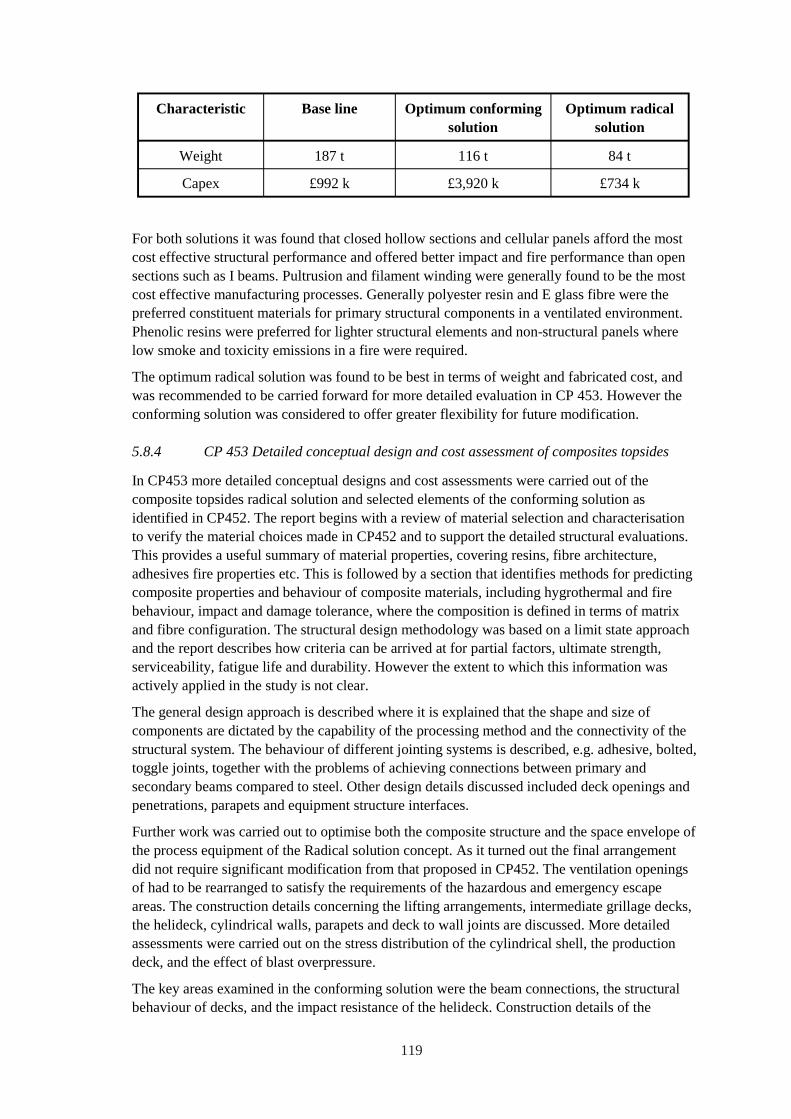
Characteristic Base line Optimum conforming Optimum radical solution solution
Weight 187 t 116 t 84 t
Capex £992 k £3,920 k £734 k
For both solutions it was found that closed hollow sections and cellular panels afford the most cost effective structural performance and offered better impact and fire performance than open sections such as I beams. Pultrusion and filament winding were generally found to be the most cost effective manufacturing processes. Generally polyester resin and E glass fibre were the preferred constituent materials for primary structural components in a ventilated environment. Phenolic resins were preferred for lighter structural elements and non-structural panels where low smoke and toxicity emissions in a fire were required.
The optimum radical solution was found to be best in terms of weight and fabricated cost, and was recommended to be carried forward for more detailed evaluation in CP 453. However the conforming solution was considered to offer greater flexibility for future modification.
5.8.4 CP 453 Detailed conceptual design and cost assessment of composites topsides
In CP453 more detailed conceptual designs and cost assessments were carried out of the composite topsides radical solution and selected elements of the conforming solution as identified in CP452. The report begins with a review of material selection and characterisation to verify the material choices made in CP452 and to support the detailed structural evaluations. This provides a useful summary of material properties, covering resins, fibre architecture, adhesives fire properties etc. This is followed by a section that identifies methods for predicting composite properties and behaviour of composite materials, including hygrothermal and fire behaviour, impact and damage tolerance, where the composition is defined in terms of matrix and fibre configuration. The structural design methodology was based on a limit state approach and the report describes how criteria can be arrived at for partial factors, ultimate strength, serviceability, fatigue life and durability. However the extent to which this information was actively applied in the study is not clear.
The general design approach is described where it is explained that the shape and size of components are dictated by the capability of the processing method and the connectivity of the structural system. The behaviour of different jointing systems is described, e.g. adhesive, bolted, toggle joints, together with the problems of achieving connections between primary and secondary beams compared to steel. Other design details discussed included deck openings and penetrations, parapets and equipment structure interfaces.
Further work was carried out to optimise both the composite structure and the space envelope of the process equipment of the Radical solution concept. As it turned out the final arrangement did not require significant modification from that proposed in CP452. The ventilation openings of had to be rearranged to satisfy the requirements of the hazardous and emergency escape areas. The construction details concerning the lifting arrangements, intermediate grillage decks, the helideck, cylindrical walls, parapets and deck to wall joints are discussed. More detailed assessments were carried out on the stress distribution of the cylindrical shell, the production deck, and the effect of blast overpressure.
The key areas examined in the conforming solution were the beam connections, the structural behaviour of decks, and the impact resistance of the helideck. Construction details of the
119
columns and primary / secondary beams are described together with the connections between the beams and beams and decks. The more detailed analysis investigated the effect of long term creep in primary beams, viability of tubular beam options, the stresses at a beam to column connection and elastic resilience of the helideck to impact
The report includes a detailed hazard assessment and analysis of the response of the platform to fire and blast and the details for site assembly and fabrication are covered at length. The latter includes comment about health and safety issues, handling, workforce training and inspection and repair.
The requirements for platform installation are discussed where it is noted that the lower weight of a composite structure would afford no appreciable advantage for most practical situations. This is because of the ample lift capacity of vessels general available for installation. However the effect of weight reduction on the installed cost of floating facilities such as TLP's and semisubmersibles was shown to be significant.
Comment is given about the factors dictating the process which would enable composites to be implemented in structural applications offshore. It is suggested this would require close cooperation between one or more operators, a main contractor and a number of specialist designers and product suppliers. The cost of carrying out a comprehensive testing program to validate the design was identified as likely to be significant. There is a need to educate personnel concerned with the design, fabrication and certification of composite structures and to encourage the development of suitable design codes.
Significant effort was applied comparing the construction costs, in terms of material and fabrication cost, for the base line and radical solutions on a like-for-like basis. Just the production deck was costed for the Conforming option to enable an estimate of the complete platform to be obtained. The all composite Radical solution was shown to weigh 50 % of the steel base line and to have a Capex that was 20 % lower.
Limited information was made available of the origin of the design and partial factors used by MSP in the study. The claimed weight and cost savings for both composite designs were dependent on the choice of these factors.
5.8.5 Significance
This was the first major study carried out to investigate the practicalities of constructing primary structures using composite materials on offshore platforms. The study found that it was technically and economically viable to construct primary structures for the topside of minimum facilities production platform almost entirely out of composite materials given a large enough order base to limit the effect of one off-costs.
5.9 DNV Recommended Standard Composite Components
5.9.1 Introduction
ARP sponsors were collectively participants of a DNV Joint Industry Project to develop a general performance based guideline for the design of load carrying structures and components fabricated from fibre reinforced plastics and sandwich structures.
120
5.9.2 Description of guideline
The philosophy behind the guideline is material independent. The Limit State design method recognises the different modes of failure of each functional requirement and the need to associate each mode of failure with a specific limit state beyond which the structure would no longer satisfy the functional requirement. Different limit states are defined, each limit state being related to the kind of failure mode and its anticipated consequences. Both ultimate limit state (ULS) and serviceability limit state (SLS) are required to be considered in the design of the structure. Safety classes are determined based on the consequences of failure when the mode of failure is related to the ultimate limit state. Service classes are based on the frequency of service interruptions or restrictions caused by modes of failure related to the serviceability limit state. These modes of failure imply no risk of human injury and minor environmental consequences. The target safety depends on the failure type and the safety class. The structural reliability of the structure is ensured by the use of partial safety factors specified in the guideline.
The design analysis consists in associating each mode of failure to all the possible failure mechanisms (i.e. the mechanisms at the material level). A design equation or a failure criterion is defined for each failure mechanism, and failure becomes interpreted as synonymous to the design equation no longer being satisfied. The design equations are formulated in the so-called load and resistance factor design (LRFD) format, where partial safety factors (load factors and resistance factors) are applied to the load effects (characteristic load values) and to the resistance variables (characteristic resistance values) that enter the design equations. As an alternative to the LRFD format a recognised Structural Reliability Analysis (SRA) may be applied. Loads and safety factors are based on probabilistic representations and guidance is provided about the type of distribution type to be used and how to treat the combination of loads and environmental conditions.
The structural analysis section is specific towards the treatment of composite materials and is based on a ply level analysis. Material properties can be treated at both the ply level or the constituent level. Guidance is provided about linear and non-linear analytical methods for different types of structure, e.g. sandwich, and treatment of modelling aspects using finite elements. The guideline requires that the dependence of material properties to strain rate be taken into account. However at the time of writing none of the ARP guidance information related to design methods for impact or fire had been considered. Guidance is given about progressive failure analysis, stress concentration effects and fracture models and the requirements for handling different failure criteria and mechanisms. The latter include but are not limited to fibre and matrix failure, yielding, buckling, creep, fatigue and stress rupture.
The guideline provides detailed information out typical material properties and how to generate data by testing. Guidance is also provided about the use of component testing for qualification testing, or quality control purposes. The testing may be also used to reduce specific uncertainties related to effects of load combinations, scaling effects and failure mechanisms. The intention is that the guideline will also provide guidance about the requirements for fabrication of components, in service inspection and repair.
5.9.3 Significance
This guideline provides an important source document to facilitate the design and fabrication of composite material structures for use in offshore applications. Further information is available from Dr. Andreas Echtermeyer at [email protected]
121
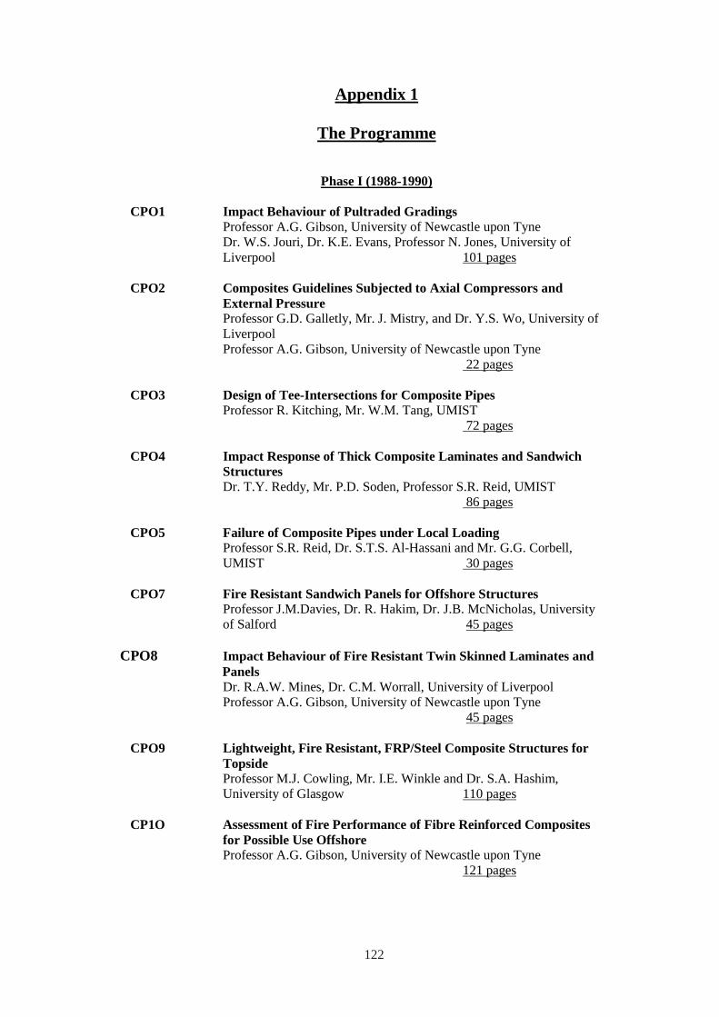
Appendix 1
The Programme
Phase I (1988-1990)
CPO1 Impact Behaviour of Pultraded Gradings Professor A.G. Gibson, University of Newcastle upon Tyne Dr. W.S. Jouri, Dr. K.E. Evans, Professor N. Jones, University of Liverpool 101 pages
CPO2 Composites Guidelines Subjected to Axial Compressors andExternal PressureProfessor G.D. Galletly, Mr. J. Mistry, and Dr. Y.S. Wo, University of Liverpool Professor A.G. Gibson, University of Newcastle upon Tyne
22 pages
CPO3 Design of Tee-Intersections for Composite Pipes Professor R. Kitching, Mr. W.M. Tang, UMIST
72 pages
CPO4 Impact Response of Thick Composite Laminates and Sandwich Structures Dr. T.Y. Reddy, Mr. P.D. Soden, Professor S.R. Reid, UMIST
86 pages
CPO5 Failure of Composite Pipes under Local Loading Professor S.R. Reid, Dr. S.T.S. Al-Hassani and Mr. G.G. Corbell, UMIST 30 pages
CPO7 Fire Resistant Sandwich Panels for Offshore Structures Professor J.M.Davies, Dr. R. Hakim, Dr. J.B. McNicholas, University of Salford 45 pages
CPO8 Impact Behaviour of Fire Resistant Twin Skinned Laminates and Panels Dr. R.A.W. Mines, Dr. C.M. Worrall, University of Liverpool Professor A.G. Gibson, University of Newcastle upon Tyne
45 pages
CPO9 Lightweight, Fire Resistant, FRP/Steel Composite Structures for Topside Professor M.J. Cowling, Mr. I.E. Winkle and Dr. S.A. Hashim, University of Glasgow 110 pages
CP1O Assessment of Fire Performance of Fibre Reinforced Composites for Possible Use Offshore Professor A.G. Gibson, University of Newcastle upon Tyne
121 pages
122
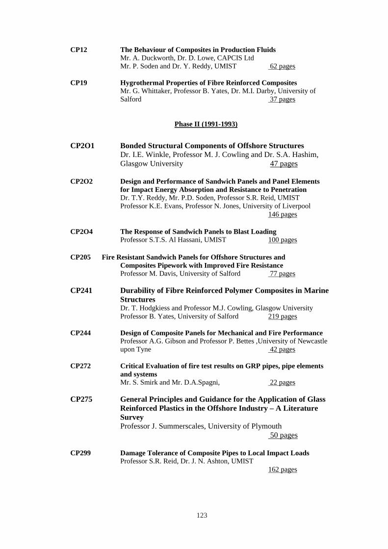
CP12 The Behaviour of Composites in Production Fluids Mr. A. Duckworth, Dr. D. Lowe, CAPCIS Ltd Mr. P. Soden and Dr. Y. Reddy, UMIST 62 pages
CP19 Hygrothermal Properties of Fibre Reinforced Composites Mr. G. Whittaker, Professor B. Yates, Dr. M.I. Darby, University of Salford 37 pages
Phase II (1991-1993)
CP2O1 Bonded Structural Components of Offshore Structures Dr. I.E. Winkle, Professor M. J. Cowling and Dr. S.A. Hashim, Glasgow University 47 pages
CP2O2 Design and Performance of Sandwich Panels and Panel Elements for Impact Energy Absorption and Resistance to Penetration Dr. T.Y. Reddy, Mr. P.D. Soden, Professor S.R. Reid, UMIST Professor K.E. Evans, Professor N. Jones, University of Liverpool
146 pages
CP2O4 The Response of Sandwich Panels to Blast Loading Professor S.T.S. Al Hassani, UMIST 100 pages
CP205 Fire Resistant Sandwich Panels for Offshore Structures and Composites Pipework with Improved Fire Resistance Professor M. Davis, University of Salford 77 pages
CP241 Durability of Fibre Reinforced Polymer Composites in Marine Structures Dr. T. Hodgkiess and Professor M.J. Cowling, Glasgow University Professor B. Yates, University of Salford 219 pages
CP244 Design of Composite Panels for Mechanical and Fire Performance Professor A.G. Gibson and Professor P. Bettes ,University of Newcastle upon Tyne 42 pages
CP272 Critical Evaluation of fire test results on GRP pipes, pipe elements and systems Mr. S. Smirk and Mr. D.A.Spagni, 22 pages
CP275 General Principles and Guidance for the Application of Glass Reinforced Plastics in the Offshore Industry – A Literature Survey Professor J. Summerscales, University of Plymouth
50 pages
CP299 Damage Tolerance of Composite Pipes to Local Impact Loads Professor S.R. Reid, Dr. J. N. Ashton, UMIST
162 pages
123
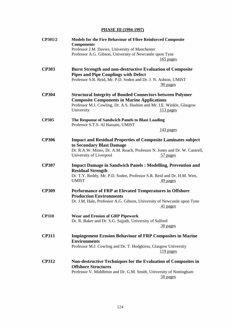
PHASE III (1994-1997)
CP301/2 Models for the Fire Behaviour of Fibre Reinforced Composite Components Professor J.M. Davies, University of Manchester Professor A.G. Gibson, University of Newcastle upon Tyne
165 pages
CP303 Burst Strength and non-destructive Evaluation of Composite Pipes and Pipe Couplings with Defect Professor S.R. Reid, Mr. P.D. Soden and Dr. J. N. Ashton, UMIST
90 pages
CP304 Structural Integrity of Bonded Connectors between Polymer Composite Components in Marine Applications Professor M.J. Cowling, Dr. A.S. Hashim and Mr. I.E. Winkle, Glasgow University 113 pages
CP305 The Response of Sandwich Panels to Blast Loading Professor S.T.S. Al Hassani, UMIST
143 pages
CP306 Impact and Residual Properties of Composite Laminates subject to Secondary Blast Damage Dr. R.A.W. Mines, Dr. A.M. Roach, Professor N. Jones and Dr. W. Cantrell, University of Liverpool 57 pages
CP307 Impact Damage in Sandwich Panels : Modelling, Prevention and Residual Strength Dr. T.Y. Reddy, Mr. P.D. Soden, Professor S.R. Reid and Dr. H.M. Wen, UMIST 49 pages
CP309 Performance of FRP at Elevated Temperatures in Offshore Production Environments Dr. J.M. Hale, Professor A.G. Gibson, University of Newcastle upon Tyne
41 pages
CP310 Wear and Erosion of GRP Pipework Dr. R. Baker and Dr. S.G. Sajjadi, University of Salford
30 pages
CP311 Impingement Erosion Behaviour of FRP Composites in Marine Environments Professor M.J. Cowling and Dr. T. Hodgkiess, Glasgow University
119 pages
CP312 Non-destructive Techniques for the Evaluation of Composites in Offshore Structures Professor V. Middleton and Dr. G.M. Smith, University of Nottingham
50 pages
124
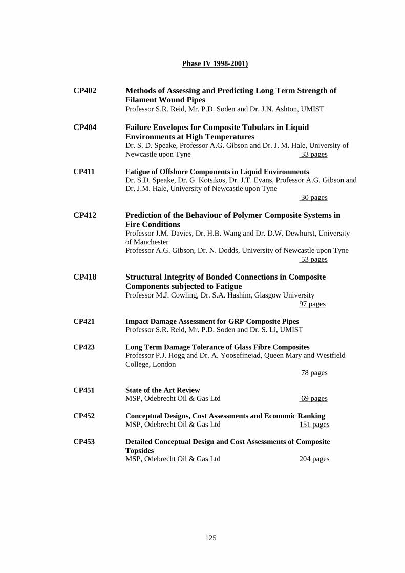
Phase IV 1998-2001)
CP402 Methods of Assessing and Predicting Long Term Strength of Filament Wound Pipes Professor S.R. Reid, Mr. P.D. Soden and Dr. J.N. Ashton, UMIST
CP404 Failure Envelopes for Composite Tubulars in Liquid Environments at High Temperatures Dr. S. D. Speake, Professor A.G. Gibson and Dr. J. M. Hale, University of Newcastle upon Tyne 33 pages
CP411 Fatigue of Offshore Components in Liquid Environments Dr. S.D. Speake, Dr. G. Kotsikos, Dr. J.T. Evans, Professor A.G. Gibson and Dr. J.M. Hale, University of Newcastle upon Tyne
30 pages
CP412 Prediction of the Behaviour of Polymer Composite Systems in Fire Conditions Professor J.M. Davies, Dr. H.B. Wang and Dr. D.W. Dewhurst, University of Manchester Professor A.G. Gibson, Dr. N. Dodds, University of Newcastle upon Tyne
53 pages
CP418 Structural Integrity of Bonded Connections in Composite Components subjected to Fatigue Professor M.J. Cowling, Dr. S.A. Hashim, Glasgow University
97 pages
CP421 Impact Damage Assessment for GRP Composite Pipes Professor S.R. Reid, Mr. P.D. Soden and Dr. S. Li, UMIST
CP423 Long Term Damage Tolerance of Glass Fibre Composites Professor P.J. Hogg and Dr. A. Yoosefinejad, Queen Mary and Westfield College, London
78 pages
CP451 State of the Art Review MSP, Odebrecht Oil & Gas Ltd 69 pages
CP452 Conceptual Designs, Cost Assessments and Economic Ranking MSP, Odebrecht Oil & Gas Ltd 151 pages
CP453 Detailed Conceptual Design and Cost Assessments of Composite Topsides MSP, Odebrecht Oil & Gas Ltd 204 pages
125
Appendix 2
Programme Team Leaders and Principal Investigators
Phase 1 (1998-1990)
Dr. S.T.S. Al-Hassani, Department of Mechanical Engineering, UMIST.
Professor M.J. Cowling, Glasgow Marine Technology Centre, University of Glasgow.
Professor J. M. Davies, Department of Civil Engineering, University of Salford.
Mr. A. Duckworth, CAPCIS.
Dr. K. E. Evans, Department of Materials Science and Engineering, University of Liverpool.
Professor G. Galletly, Department of Mechanical Engineering, University of Liverpool.
Dr. A.G. Gibson, Department of Metallurgy and Material Sciences, University of Liverpool.
Dr. J. Hure, Queen Mary College.
Professor N. Jones, Department of Mechanical Engineering, University of Liverpool.
Professor R. Kitching, Department of Mechanical Engineering, UMIST.
Dr. D. Lowe, CAPCIS.
Dr. J. McNicholas, Department of Civil Engineering, University of Salford.
Dr. R. Mines, Department of Mechanical Engineering, University of Liverpool.
Dr. T.Y. Reddy, Department of Mechanical Engineering, UMIST.
Professor S.R. Reid, Department of Mechanical Engineering, UMIST.
Mr. P. D. Soden, Department of Mechanical Engineering, UMIST.
Dr. I.E. Winkle, Glasgow Marine Technology Centre, University of Glasgow.
Dr. G. H. Wolstenholm, Department of Mathematics, University of Salford.
Professor B. Yates, Department of Mathematics, University of Salford.
126
Phase II (1991-1993)
Dr. S.T.S. Al-Hassani, Department of Mechanical Engineering, UMIST.
Dr. J.N. Ashton, Department of Mechanical Engineering, UMIST.
Professor P. Bettess, Department of Marine Technology, University of Newcastle Upon Tyne.
Professor M.J. Cowling, Glasgow Marine Technology Centre, University of Glasgow.
Professor J. M. Davies, Department of Civil Engineering, University of Salford.
Dr. K. E. Evans, Department of Materials Science and Engineering, University of Liverpool.
Professor A.G. Gibson, Department of Mechanical, Materials and ManufacturingEngineering, University of Newcastle Upon Tyne.
Dr. S.A. Hashim, Glasgow Marine Technology Centre, University of Glasgow.
Dr. T. Hodgkiess, Glasgow Marine Technology Centre, University of Glasgow.
Professor N. Jones, Department of Mechanical Engineering, University of Liverpool.
Dr. T.Y. Reddy, Department of Mechanical Engineering, UMIST.
Professor S.R. Reid, Department of Mechanical Engineering, UMIST.
Mr. S. Smirk, Marinetech Research.
Mr. P. D. Soden, Department of Mechanical Engineering, UMIST.
Mr. D. A. Spagni, Marinetech Research.
Professor J. Summerscales, University of Plymouth.
Dr. I.E. Winkle, Glasgow Marine Technology Centre, University of Glasgow.
Professor B. Yates, Department of Mathematics, University of Salford.
127
Phase III (1994-1997)
Dr. S.T.S. Al-Hassani, Department of Mechanical Engineering, UMIST.
Dr. K. Alderson, Department of Materials Science and Engineering, Impact Research Centre, University of Liverpool.
Dr. J.N. Ashton, Department of Mechanical Engineering, UMIST.
Dr. R. Baker, Department of Civil Engineering and Construction, University of Salford.
Dr. R. W. Barber, Department of Civil Engineering and Construction, University of Salford.
Professor P. Bettess, Department of Marine Technology, University of Newcastle UponTyne.
Dr. H.W. Chandler, Department of Mechanical, Materials and Manufacturing Engineering,University of Newcastle Upon Tyne.
Professor M.J. Cowling, Glasgow Marine Technology Centre, University of Glasgow.
Professor J. M. Davies, Department of Civil Engineering and Construction, University ofSalford.
Dr. K. E. Evans, Department of Materials Science and Engineering, University of Liverpool.
Professor A.G. Gibson, Department of Mechanical, Materials and ManufacturingEngineering, University of Newcastle Upon Tyne.
Dr. J. M. Hale, Department of Mechanical, Materials and Manufacturing Engineering,University of Newcastle Upon Tyne.
Dr. S.A. Hashim, Glasgow Marine Technology Centre, University of Glasgow.
Dr. T. Hodgkiess, Glasgow Marine Technology Centre, University of Glasgow.
Professor N. Jones, Department of Mechanical Engineering, Impact Research Centre,University of Liverpool.
Dr. J. B. McNicholas, Department of Civil Engineering and Construction, University ofSalford.
Dr. V. Middleton, Department of Mechanical Engineering, UMIST.
Dr. R. Mines, Department of Mechanical Engineering, University of Liverpool.
Dr. T.Y. Reddy, Department of Mechanical Engineering, UMIST.
Professor S.R. Reid, Department of Mechanical Engineering, UMIST.
Dr. S. G. Sajjadi, Department of Mathematics, University of Salford.
Dr. G. M. Smith, Department of Mechanical Engineering, University of Nottingham.
Mr. S. Smirk, Marinetech Research.
128
Mr. P. D. Soden, Department of Mechanical Engineering, UMIST.
Mr. D. A. Spagni, Marinetech Research.
Dr. I.E. Winkle, Glasgow Marine Technology Centre, University of Glasgow.
Phase IV (1998-2001)
Dr. J.N. Ashton, Department of Mechanical Engineering, UMIST.
Professor M.J. Cowling, Glasgow Marine Technology Centre, University of Glasgow.
Professor J. M. Davies, Department of Civil and Structural Engineering, University of Manchester.
Dr. J. T. Evans, Centre for Composite Materials Engineering, University of Newcastle UponTyne.
Professor A.G. Gibson, Centre for Composite Materials Engineering, University ofNewcastle Upon Tyne.
Dr. J. M. Hale, Centre for Composite Materials Engineering, University of Newcastle UponTyne.
Dr. S.A. Hashim, Glasgow Marine Technology Centre, University of Glasgow.
Dr. P. J. Hogg, Materials Department, Queen Mary & Westfield College.
Professor I. Incecik, Department of Marine Technology, University of Newastle Upon Tyne.
Dr. S. Li, Department of Mechanical Engineering, UMIST.
Professor S.R. Reid, Department of Mechanical Engineering, UMIST.
Mr. P. D. Soden, Department of Mechanical Engineering, UMIST.
129
Appendix 3
Membership of the Programme Steering Committee
Phase 1 (1998-1990)
Mr. R. Maybourn OBE, Chairman
Dr. P. Abrams, Exxon Mr. J. Alkire, Amoco Research Mr. J.C. Andrew, VSEL Mr. J. Aubrey, VSEL Mr. N. Baker, Total Oil Marine Mr. D. Batte, British Gas Mr. I. Brown, MTD.EPSRC Mr. A. Cohil, Agip UK Dr. R. Connell, Shell Expro Dr. D. Ellix, MATSU Mr. J. Foot, Offshore Supplies Office Dr. A.G. Gibson, University of Liverpool Dr. G. Green, Ciba-Geigy Mrs. V. Hervouet, Elf UK Mr. C. Houghton, Phillips Petroleum Dr. L. Jones, British Gas Dr. F. Knight, Department of Energy Mr. J. Love, Total Oil Marine Mr. M Michelon, AGIP Dr. P. Medlicott, BP Research Mr. T. Meland, Statoil Mr. J. Nixon, Vosper Thorneycroft Mr. A. O'Connor, Dow Europe Mr. P. Oldham, Kerr McGee Oil UK Mr. J. Quinn, Fibreforce Composites Mr. R. Reed, Amoco (UK) Dr. A. Savadori, Enichem Mr. M. Seamark, Balmoral Group Dr. C. Smith, Ministry of Defence Mr. D.A. Spagni, Marinetech North West Mr. A. Stokes, BP Exe. Mr. A. Thompson, BP Exe. Mr. M. Truchon, Elf Aquitaine Mr. M. Turner, Marinetech North West Mr. F. Vidouse, Elf Aquitaine Mr. I. Walker, Vosper Thorneycroft Mr. A. Wilson, Total Oil Marine Mr. W. Woodhouse, Mobil
130
Phase II (1991-1993)
Mr. R. Maybourn OBE, Chairman
Dr. D. Allison, Ministry of Defence, (PE) Mr. A. Almeida, Brasoil UK Ltd Mr. N. Baker, Total Oil Marine Mr. K. Beaumont, Hunting Engineering Ltd. Dr. P. Boothby, British Gas Research Centre Dr. A. Burns, Elf UK Dr. J. Chang, Exxon Production Research Co. Mr. W. Cole, Amoco Research Centre Dr R. Connell, Shell Expro Mr. G. Crouch, Department of Energy Dr. A. Cutler, Conoco UK Mr. P. Darby, Cray Valley Products Dr. C. Del Vecchio, Petrobras Research and Development Centre Dr. D. Ellix, Amerada Hess Ltd. Professor A.G. Gibson, The University of Newcastle Upon Tyne Mr M. Gohil, AGIP (UK) Mr. P. Harrison, Dow Deutschland Inc. Mr. C. Houghton, Phillips Petroleum UK Ltd Dr. L. Jones, British Gas Research Centre Mr. A. King, Vosper Thornycroft (UK) Ltd Mr. A. Mableson, Vosper Thornycroft (UK) Ltd Mr. M. Mansell, Kerr McGee Oil (UK) plc Dr. P. Medlicott, BP Research Centre Mr. T. Meland, Statoil Mr. B. Melve, Statoil Mr. G. Mitchinson, Amoco UK Mr. W. Monkhouse, Department of Energy MaTSU Mr. B. Morsund, Norsk Hydro Mr. D. Osborne, Ameron Fiberglass Pipe Division Mr. T. Pendlington, BP Exploration Mr. A. Porcari, AGIP/Tein Mr. R. Pritchard, Total Oil Marine plc Mr. M. Pye, Bow Valley Petroleum (UK) Ltd Dr. L. Scharfstein, Mobil R&D Corp. Mr. M. Seamark, Balmoral Group Mr. P. Simpson, Hunting Engineering Ltd Mr. J. Smith, Amoco (UK) Exploration Co. Mr. D. Spagni, Marinetech Research Mr. M. Staunton-Lambert, Marine Technology Directorate Ltd. Mr. P. Tolhoek, Ameron BV Mr. F. Vidouse, Groupe Elf Aquitaine Mr. I. Wattie, Conoco (UK) Ltd Dr. J. Williams, Conoco (UK) Ltd Mr. W. Woodhouse, Mobil R&D Corp.
131

Phase III (1994-1997)
Mr. R. Maybourn OBE, Chairman
Dr. D. Allison, Ministry of Defence, (PE) Dr. T. Al-Hassan, Health and Safety Executive Mr. N. J. Baker, Total Oil Marine Mr. K. Beaumont, Hunting Engineering Ltd. Mr. J. Bird, Ministry of Defence (PE) Dr. P. Boothby, British Gas Research Centre Dr. A. Burns, Elf UK Dr. J. Chang, Exxon Production Research Co. Mr. W. Cole, Amoco Research Centre Dr. J. Cook, Defence Research Agency Dr R. Connell, Shell Expro Mr. R. Court, Structural Materials Centre, HM Naval Base, Dunfermline Mrs. J. Dalzel-Job, Structural Materials Centre, HM Naval Base, Dunfermline Mr. P. Darby, Cray Valley Products Dr. C. Del Vecchio, Petrobras Research and Development Centre Mr. S. Frost, Koninklijke/Shell Laboratorium Professor A.G. Gibson, The University of Newcastle Upon Tyne Mr. R. Graham, Ameron Fibreglass Pipe Division Dr. P. Hill, British Gas Research & Development, Gas Research Centre Mr. C. Houghton, Amoco UK Exploration Co. Dr. L. Jones, British Gas Research & Development, Gas Research Centre Dr. A. Lou, Phillips Petroleum Co. Dr. J. Lowe, Balmoral Group Mr. T. McGovern, Conoco (UK) Ltd Mr. R. Mableson, Vosper Thornycroft (UK) Ltd Dr. P. Medlicott, BP Research Centre Mr. T. Meland, Statoil Mr. B. Melve, Statoil Mr. L. Meniconi, Petrobras Mr. J. Mitchinson, Amoco (UK) Mr. B. Morsund, Norsk Hydro Mme. M-F Pays, Electricite de France Mr. M. Phillips, Hunting Engineering Ltd. Mr. R. Pritchard, Total Oil Marine plc Dr. J. Robertson, MaTSU Mr. M. Seamark, Balmoral Group Dr. A. Stacey, Health and Safety Executive Mr. D. Spagni, Marinetech Research Mr. M. Staunton-Lambert, Marine Technology Directorate Ltd. Dr. J. Steen, Ameron BV Mr. K. Stokes, Balmoral Group Dr. J. Sumpter, Defence Research Agency Mr. M. Swidzinski, Phillips Petroleum (UK) Ltd Mr. P. Tolhoek, Ameron BV Mr. G. Ventress, Hunting Engineering Ltd Mr. F. Vidouse, Groupe Elf Aquitaine Mr. I. Wattie, Conoco (UK) Ltd Dr. J. Williams, Conoco (UK) Ltd
132

Phase IV (1998-2001)
Mr. R. Maybourn OBE, Chairman
Dr. J. Alkire, Amoco Corporation Mr. J. Bird, Ministry of Defence (PE) Dr. A. Burns, Elf Enterprise Caledonia Dr. P. Boothby, British Gas Research Centre Mr. J. Cadei, Maunsell Structural Plastics Mr. A. Churchman, Maunsell Structural Plastics Mrs. J. Dalzel-Job, Structural Materials Centre, HM Naval Base, Dunfermline Dr. C. Del Vecchio, Petrobras Research and Development Centre Mr. C. De Souza, Health and Safety Executive Mr. F. Duesso, Elf Exploration Production Dr. A. Echtermeyer, Det Norske Veritas Mr. P. Ellis, Ministry of Defence Dr. A. Fahrer, BG Technology Mr. S. Frost, Shell International E&P Mr. D. Galbraith, Mobil North Sea Professor A.G. Gibson, The University of Newcastle Upon Tyne Mr. F. Gensous, Elf Atochem Dr. S. Groves, BP Research Centre Dr. L. Jones, British Gas Research & Development, Gas Research Centre Mr. P. Keel, Odebrecht Oil and Gas Mr. T. Kirkwood, Total Oil Marine Mr. T. Lecourtois, Electricite de France Dr. A. Lou, Phillips Petroleum Mr. R. Mableson, Vosper Thornycroft (UK) Ltd Dr. P. Medlicott, BP Research Centre Mr. T. Meland, Statoil Mr. B. Melve, Statoil Mr. L. Meniconi, Petrobras Dr. A. Nesarikar, Mobil Technology Mr. R. Patel, Health and Safety Executive Mme M.F. Pays, Electricite de France Mr. R. Sharma, Health and Safety Executive Mr. D. Smith, Hunting Engineering Mr. D. Spagni, Marinetech Research Dr. J. Steen, Ameron BV Mr. M. Swidzinski, Phillips Petroleum (UK) Ltd Mr. P. Tolhoek, Ameron BV Mr. G. Ventress, Hunting Engineering Ltd Mr. S. Williams, Odebrecht Oil and Gas
133

Printed and published by the Health and Safety ExecutiveC30 1/98
Printed and published by the Health and Safety Executive C1.25 04/03

ISBN 0-7176-2591-5
RR 039
78071 7 625 91 8£30.00 9