the cost effective use of fibre reinforced composites · pdf filethe cost effective use of...
TRANSCRIPT
The Cost Effective Use of Fibre Reinforced Composites Offshore
© Copyright, The University of Newcastle upon Tyne, MM II, all rights reserved 1
THE COST EFFECTIVE USE OFFIBRE REINFORCED
COMPOSITES OFFSHORE
Programme Summary
(1988-2001)
January 2002
The Cost Effective Use of Fibre Reinforced Composites Offshore
© Copyright, The University of Newcastle upon Tyne, MM II, all rights reserved 2
PART A: REVIEW OF APPLICATIONSOF COMPOSITE MATERIALS IN
THE OFFSHORE OIL AND GAS INDUSTRY
Professor A.G. Gibson, Programme Director of Research
Centre for Composite Materials Engineering,
University of Newcastle Upon Tyne
The Cost Effective Use of Fibre Reinforced Composites Offshore
© Copyright, The University of Newcastle upon Tyne, MM II, all rights reserved 3
CONTENTS
1. INTRODUCTION 5
2. SUMMARY OF APPLICATIONS 6
3. PIPES, TANKS AND VESSELS 9
3.1 Composite Pipework 9
3.1.1 Joining techniques 103.1.2 Steel strip laminate (SSL) pipe 123.1.3 Mechanical behaviour and failure modes 123.1.4 Applications 13
3.2 Tanks and Vessels 16
3.3 Flexible Thermosetting Tube 17
3.4 Reinforced Thermoplastic Pipe (RTP) 18
3.5 Lined Pipe 19
3.6 Rigid Risers 20
3.7 Flexible Risers 21
3.8 High Pressure Accumulator Bottles 22
3.9 Repair of metallic tubulars 23
4. STRUCTURAL APPLICATIONS 26
4.1 Blast and Fire Protection 26
4.2 Gratings and Stairways 28
4.3 Tethers and Tendons 28
5. MAJOR LOAD-BEARING STRUCTURAL USE OF COMPOSITES OFFFSHORE 29
5.1 Designers and Fabricators 31
5.2 Composites Industry Infrastructure 32
5.3 Scale-up of Fabrication Processes 32
6. RELEVANT PROPERTIES OF COMPOSITES 33
6.1 Environmental and Fatigue Behaviour 33
6.2 Fire Performance 35
6.2.1 Fire Reaction 36
6.2.2 Fire Resistance 39
6.2.3 Jet Fires Tests 39

The Cost Effective Use of Fibre Reinforced Composites Offshore
© Copyright, The University of Newcastle upon Tyne, MM II, all rights reserved 4
7. CONCLUSIONS 39
8. REFERENCES 42
The Cost Effective Use of Fibre Reinforced Composites Offshore
© Copyright, The University of Newcastle upon Tyne, MM II, all rights reserved 5
1. INTRODUCTION
This report reviews areas where composites are finding application in the oil and gasindustry, onshore and offshore. The most significant advances have been made in theareas of pipework and fluid handling, driven by light weight and corrosion resistancecompared to metals. Modest, but significant progress has also been made in structuralapplications. Lessons are being learned from successful applications with the resultthat operators, design houses and contractors are now beginning to take a seriousinterest in their wider use. Expansion is therefore expected to continue into all sectorsof the oil and gas industry. Research results and new developments have beensummarized in a number of references (ARP, 2000; ‘Composite Materials forOffshore Operations: Proceedings of the First International Workshop’, 1993;Croquette, 1994; Gibson, 1993, 2000, 2001; Institut Français du Pétrole, 1994;Salama, 1995 and Wang et al. (1999, 2000)).
Until recently, interest has focused on the use of glass fibre-based composites inonshore fluid transport and on the topsides of offshore platforms. However, theprospect of deepwater production is generating a new impetus for high performancecomposites for demanding sub sea applications. The probable scale of some new subsea developments, such as rigid risers and tethers (see Sections 3.6 and 4.3) is likelyto result in greatly increased demand for carbon based-based composites as well as forthe manufacturing facilities to process them. Composite down-hole tubing is alsobeginning to find applications sub sea and in well intervention (Section 3.3).
In many cases the purchase cost of composite components exceeds that of theirmetallic counterparts. However, because of their relative ease of handling theinstalled cost, especially of pipe systems, is often lower than that of conventionalsteels. The cost advantages are even greater when composites replace expensivecorrosion-resistant metals such as copper-nickel alloys, duplex or super duplexstainless steel or even titanium. Their corrosion resistance also improves reliabilityand leads to lower through-life costs.
As well as expected benefits, a number of barriers to the use of composites offshorewere identified in the 1980’s. These were:
1. Regulatory requirements, especially on combustibility2. Lack of relevant performance information, especially in hostile offshore
environments (including erosion, fatigue, wear and impact abuse, as wellas fluid environments).
3. Lack of efficient design procedures and working standards, combined withunfamiliarity on the part of designers
4. The fragmented structure of the composites industry, and5. Difficulty of scaling up fabrication processes to make very large composite
structures
The majority of research undertaken on offshore composites in the last two decadeshas been aimed at the removal of barriers 1-3, and much has been achieved, especiallyin the regulatory area where ‘prescriptive’ requirements have been largely replaced by‘performance-based’ or ‘goal-setting’ones. Some remaining problems associated withinfrastructure and process technologies will be discussed in Section 5.2.
The Cost Effective Use of Fibre Reinforced Composites Offshore
© Copyright, The University of Newcastle upon Tyne, MM II, all rights reserved 6
2 SUMMARY OF APPLICATIONS
The most successful offshore applications for composites have been in pipework foraqueous liquids. Performance-based guidelines for the design of glass fibre reinforcedepoxy (GRE) pipes have significantly accelerated these applications. These wereinitiated by UKOOA (United Kingdom Offshore Operators Association (1994) andhas recently resulted a draft ISO standard (ISO 2000).
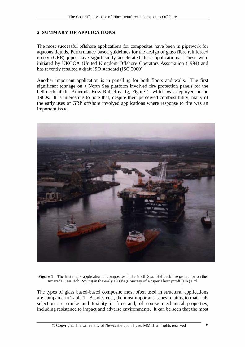
Another important application is in panelling for both floors and walls. The firstsignificant tonnage on a North Sea platform involved fire protection panels for theheli-deck of the Amerada Hess Rob Roy rig, Figure 1, which was deployed in the1980s. It is interesting to note that, despite their perceived combustibility, many ofthe early uses of GRP offshore involved applications where response to fire was animportant issue.
Figure 1 The first major application of composites in the North Sea. Helideck fire protection on theAmerada Hess Rob Roy rig in the early 1980’s (Courtesy of Vosper Thornycroft (UK) Ltd.
The types of glass based-based composite most often used in structural applicationsare compared in Table 1. Besides cost, the most important issues relating to materialsselection are smoke and toxicity in fires and, of course mechanical properties,including resistance to impact and adverse environments. It can be seen that the most
The Cost Effective Use of Fibre Reinforced Composites Offshore
© Copyright, The University of Newcastle upon Tyne, MM II, all rights reserved 7
important structural materials, epoxy, vinyl ester and polyester, would probably beprevented from use in areas where smoke and toxicity would be a problem (Gibson,2001). The most favourable systems from the viewpoint of toxicity are those basedon phenolic resins. Modified acrylic resins, such as Modar, may also be used incertain toxicity-sensitive areas, but this resin type has yet to be widely used offshore.
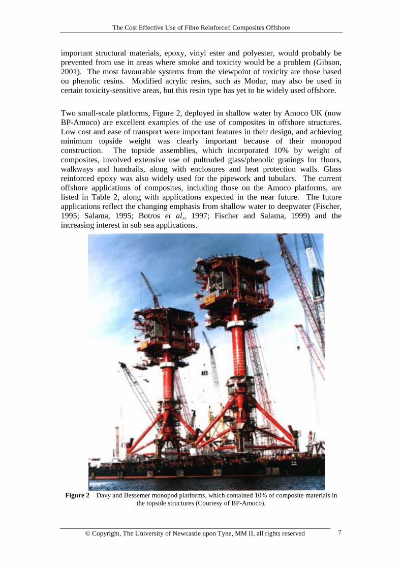
Two small-scale platforms, Figure 2, deployed in shallow water by Amoco UK (nowBP-Amoco) are excellent examples of the use of composites in offshore structures.Low cost and ease of transport were important features in their design, and achievingminimum topside weight was clearly important because of their monopodconstruction. The topside assemblies, which incorporated 10% by weight ofcomposites, involved extensive use of pultruded glass/phenolic gratings for floors,walkways and handrails, along with enclosures and heat protection walls. Glassreinforced epoxy was also widely used for the pipework and tubulars. The currentoffshore applications of composites, including those on the Amoco platforms, arelisted in Table 2, along with applications expected in the near future. The futureapplications reflect the changing emphasis from shallow water to deepwater (Fischer,1995; Salama, 1995; Botros et al,, 1997; Fischer and Salama, 1999) and theincreasing interest in sub sea applications.
Figure 2 Davy and Bessemer monopod platforms, which contained 10% of composite materials inthe topside structures (Courtesy of BP-Amoco).
The Cost Effective Use of Fibre Reinforced Composites Offshore
© Copyright, The University of Newcastle upon Tyne, MM II, all rights reserved 8
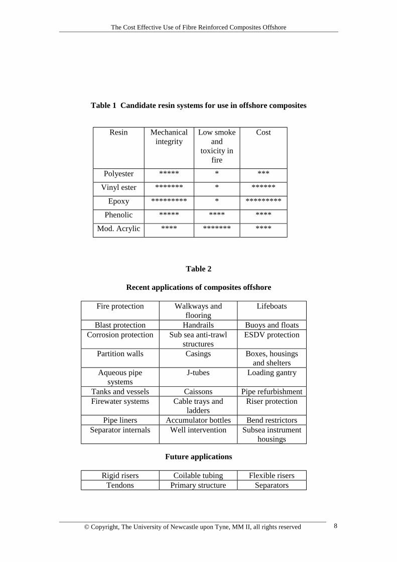
Table 1 Candidate resin systems for use in offshore composites
Resin Mechanicalintegrity
Low smokeand
toxicity infire
Cost
Polyester ***** * ***
Vinyl ester ******* * ******
Epoxy ********* * *********
Phenolic ***** **** ****
Mod. Acrylic **** ******* ****
Table 2
Recent applications of composites offshore
Fire protection Walkways andflooring
Lifeboats
Blast protection Handrails Buoys and floatsCorrosion protection Sub sea anti-trawl
structuresESDV protection
Partition walls Casings Boxes, housingsand shelters
Aqueous pipesystems
J-tubes Loading gantry
Tanks and vessels Caissons Pipe refurbishmentFirewater systems Cable trays and
laddersRiser protection
Pipe liners Accumulator bottles Bend restrictorsSeparator internals Well intervention Subsea instrument
housings
Future applications
Rigid risers Coilable tubing Flexible risersTendons Primary structure Separators
The Cost Effective Use of Fibre Reinforced Composites Offshore
© Copyright, The University of Newcastle upon Tyne, MM II, all rights reserved 9
3. PIPES, TANKS AND VESSELSThis section will discuss significant areas where composites are being employed forfluid transport and storage. The key products are:
• Filament wound thermosetting Pipework• Steel strip laminate (SSL) pipe• Fibreglass tanks and vessels• Thermosetting coil tube• Reinforced thermoplastic pipework (RTP)• Lined pipe• Rigid risers, and• High pressure flexible tubing
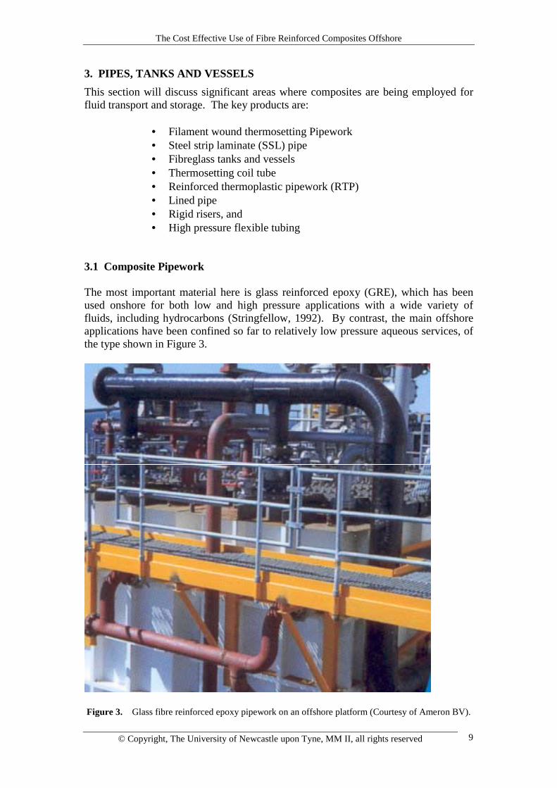
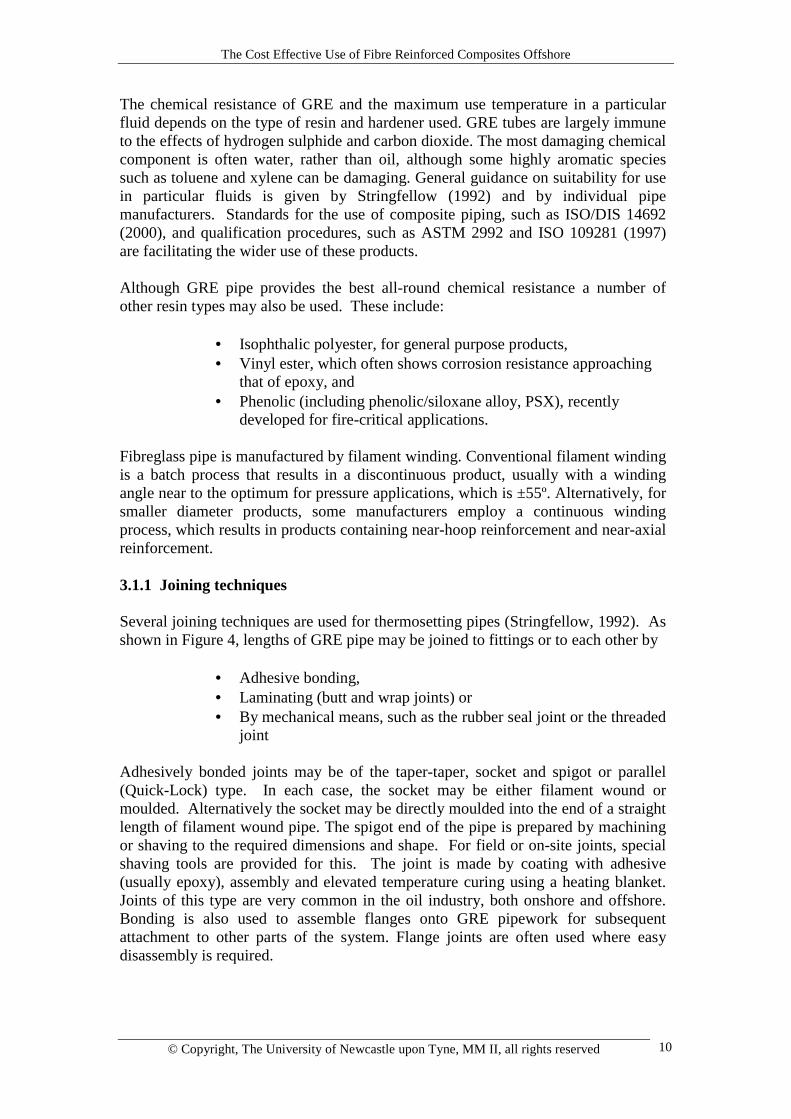
3.1 Composite Pipework The most important material here is glass reinforced epoxy (GRE), which has beenused onshore for both low and high pressure applications with a wide variety offluids, including hydrocarbons (Stringfellow, 1992). By contrast, the main offshoreapplications have been confined so far to relatively low pressure aqueous services, ofthe type shown in Figure 3.
Figure 3. Glass fibre reinforced epoxy pipework on an offshore platform (Courtesy of Ameron BV).
The Cost Effective Use of Fibre Reinforced Composites Offshore
© Copyright, The University of Newcastle upon Tyne, MM II, all rights reserved 10
The chemical resistance of GRE and the maximum use temperature in a particularfluid depends on the type of resin and hardener used. GRE tubes are largely immuneto the effects of hydrogen sulphide and carbon dioxide. The most damaging chemicalcomponent is often water, rather than oil, although some highly aromatic speciessuch as toluene and xylene can be damaging. General guidance on suitability for usein particular fluids is given by Stringfellow (1992) and by individual pipemanufacturers. Standards for the use of composite piping, such as ISO/DIS 14692(2000), and qualification procedures, such as ASTM 2992 and ISO 109281 (1997)are facilitating the wider use of these products. Although GRE pipe provides the best all-round chemical resistance a number ofother resin types may also be used. These include:
• Isophthalic polyester, for general purpose products,• Vinyl ester, which often shows corrosion resistance approaching
that of epoxy, and• Phenolic (including phenolic/siloxane alloy, PSX), recently
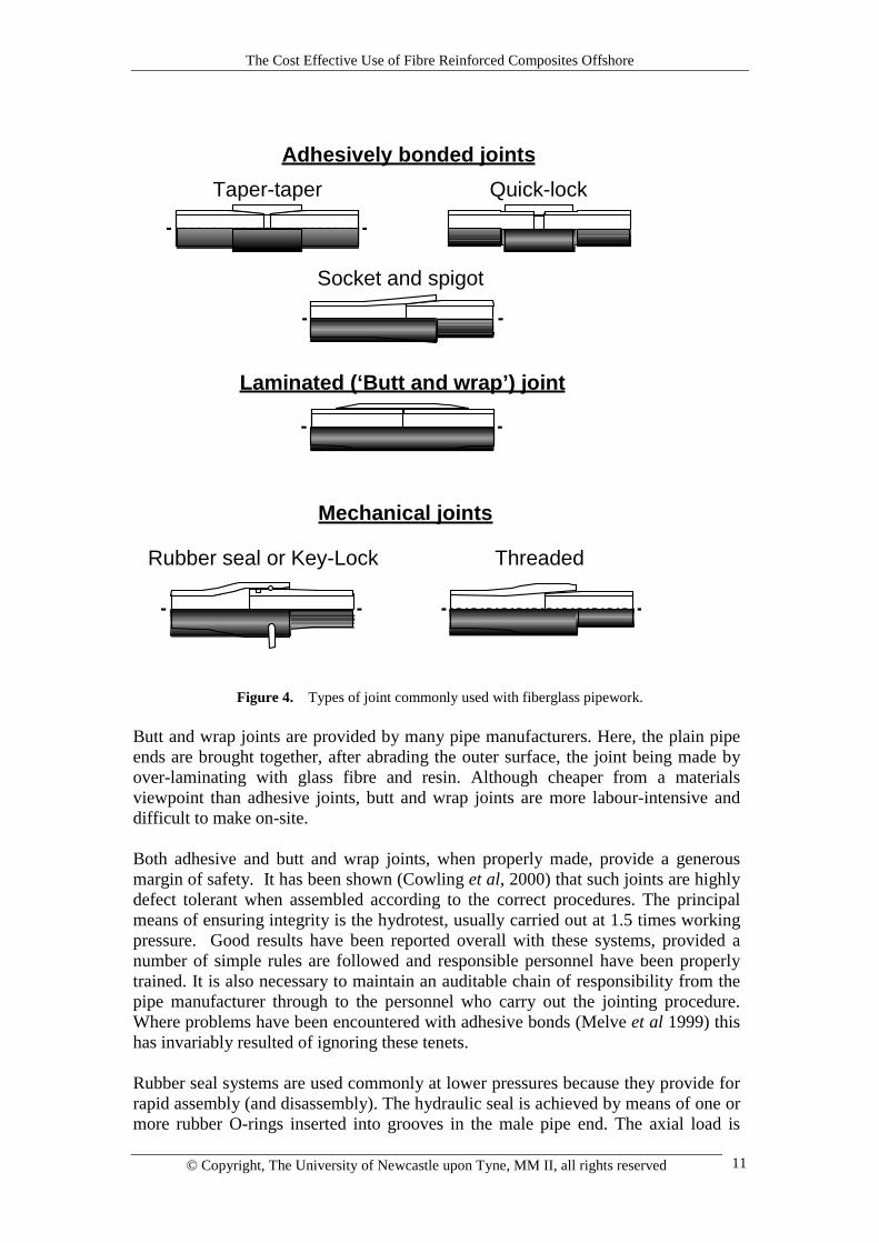
developed for fire-critical applications. Fibreglass pipe is manufactured by filament winding. Conventional filament windingis a batch process that results in a discontinuous product, usually with a windingangle near to the optimum for pressure applications, which is ±55º. Alternatively, forsmaller diameter products, some manufacturers employ a continuous windingprocess, which results in products containing near-hoop reinforcement and near-axialreinforcement. 3.1.1 Joining techniques Several joining techniques are used for thermosetting pipes (Stringfellow, 1992). Asshown in Figure 4, lengths of GRE pipe may be joined to fittings or to each other by
• Adhesive bonding,• Laminating (butt and wrap joints) or• By mechanical means, such as the rubber seal joint or the threaded
joint Adhesively bonded joints may be of the taper-taper, socket and spigot or parallel(Quick-Lock) type. In each case, the socket may be either filament wound ormoulded. Alternatively the socket may be directly moulded into the end of a straightlength of filament wound pipe. The spigot end of the pipe is prepared by machiningor shaving to the required dimensions and shape. For field or on-site joints, specialshaving tools are provided for this. The joint is made by coating with adhesive(usually epoxy), assembly and elevated temperature curing using a heating blanket.Joints of this type are very common in the oil industry, both onshore and offshore.Bonding is also used to assemble flanges onto GRE pipework for subsequentattachment to other parts of the system. Flange joints are often used where easydisassembly is required.
The Cost Effective Use of Fibre Reinforced Composites Offshore
© Copyright, The University of Newcastle upon Tyne, MM II, all rights reserved 11
Figure 4. Types of joint commonly used with fiberglass pipework. Butt and wrap joints are provided by many pipe manufacturers. Here, the plain pipeends are brought together, after abrading the outer surface, the joint being made byover-laminating with glass fibre and resin. Although cheaper from a materialsviewpoint than adhesive joints, butt and wrap joints are more labour-intensive anddifficult to make on-site. Both adhesive and butt and wrap joints, when properly made, provide a generousmargin of safety. It has been shown (Cowling et al, 2000) that such joints are highlydefect tolerant when assembled according to the correct procedures. The principalmeans of ensuring integrity is the hydrotest, usually carried out at 1.5 times workingpressure. Good results have been reported overall with these systems, provided anumber of simple rules are followed and responsible personnel have been properlytrained. It is also necessary to maintain an auditable chain of responsibility from thepipe manufacturer through to the personnel who carry out the jointing procedure.Where problems have been encountered with adhesive bonds (Melve et al 1999) thishas invariably resulted of ignoring these tenets. Rubber seal systems are used commonly at lower pressures because they provide forrapid assembly (and disassembly). The hydraulic seal is achieved by means of one ormore rubber O-rings inserted into grooves in the male pipe end. The axial load is
Rubber seal or Key-Lock Threaded
Adhesively bonded jointsTaper-taper Quick-lock
Socket and spigot
Laminated (‘Butt and wrap’) joint
Mechanical joints
The Cost Effective Use of Fibre Reinforced Composites Offshore
© Copyright, The University of Newcastle upon Tyne, MM II, all rights reserved 12
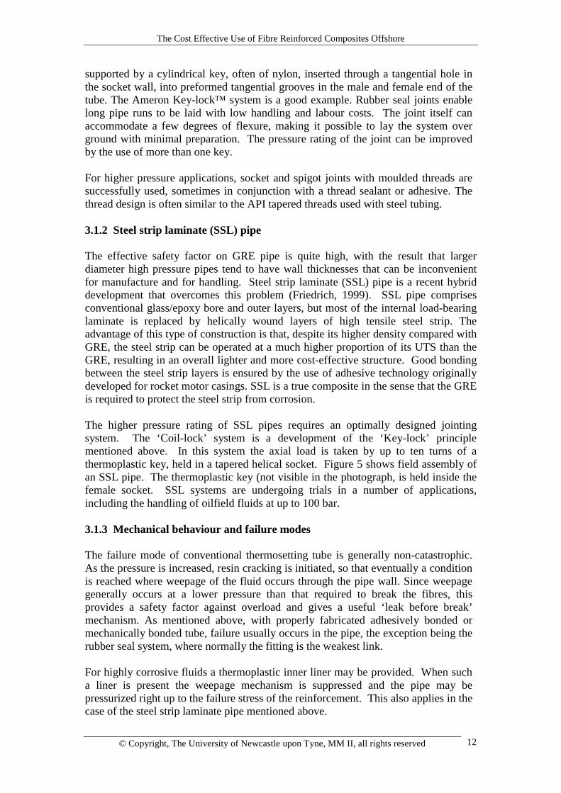
supported by a cylindrical key, often of nylon, inserted through a tangential hole inthe socket wall, into preformed tangential grooves in the male and female end of thetube. The Ameron Key-lock™ system is a good example. Rubber seal joints enablelong pipe runs to be laid with low handling and labour costs. The joint itself canaccommodate a few degrees of flexure, making it possible to lay the system overground with minimal preparation. The pressure rating of the joint can be improvedby the use of more than one key. For higher pressure applications, socket and spigot joints with moulded threads aresuccessfully used, sometimes in conjunction with a thread sealant or adhesive. Thethread design is often similar to the API tapered threads used with steel tubing. 3.1.2 Steel strip laminate (SSL) pipe The effective safety factor on GRE pipe is quite high, with the result that largerdiameter high pressure pipes tend to have wall thicknesses that can be inconvenientfor manufacture and for handling. Steel strip laminate (SSL) pipe is a recent hybriddevelopment that overcomes this problem (Friedrich, 1999). SSL pipe comprisesconventional glass/epoxy bore and outer layers, but most of the internal load-bearinglaminate is replaced by helically wound layers of high tensile steel strip. Theadvantage of this type of construction is that, despite its higher density compared withGRE, the steel strip can be operated at a much higher proportion of its UTS than theGRE, resulting in an overall lighter and more cost-effective structure. Good bondingbetween the steel strip layers is ensured by the use of adhesive technology originallydeveloped for rocket motor casings. SSL is a true composite in the sense that the GREis required to protect the steel strip from corrosion. The higher pressure rating of SSL pipes requires an optimally designed jointingsystem. The ‘Coil-lock’ system is a development of the ‘Key-lock’ principlementioned above. In this system the axial load is taken by up to ten turns of athermoplastic key, held in a tapered helical socket. Figure 5 shows field assembly ofan SSL pipe. The thermoplastic key (not visible in the photograph, is held inside thefemale socket. SSL systems are undergoing trials in a number of applications,including the handling of oilfield fluids at up to 100 bar. 3.1.3 Mechanical behaviour and failure modes The failure mode of conventional thermosetting tube is generally non-catastrophic.As the pressure is increased, resin cracking is initiated, so that eventually a conditionis reached where weepage of the fluid occurs through the pipe wall. Since weepagegenerally occurs at a lower pressure than that required to break the fibres, thisprovides a safety factor against overload and gives a useful ‘leak before break’mechanism. As mentioned above, with properly fabricated adhesively bonded ormechanically bonded tube, failure usually occurs in the pipe, the exception being therubber seal system, where normally the fitting is the weakest link. For highly corrosive fluids a thermoplastic inner liner may be provided. When sucha liner is present the weepage mechanism is suppressed and the pipe may bepressurized right up to the failure stress of the reinforcement. This also applies in thecase of the steel strip laminate pipe mentioned above.
The Cost Effective Use of Fibre Reinforced Composites Offshore
© Copyright, The University of Newcastle upon Tyne, MM II, all rights reserved 13
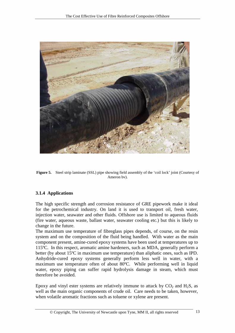
Figure 5. Steel strip laminate (SSL) pipe showing field assembly of the ‘coil lock’ joint (Courtesy ofAmeron bv).
3.1.4 Applications The high specific strength and corrosion resistance of GRE pipework make it idealfor the petrochemical industry. On land it is used to transport oil, fresh water,injection water, seawater and other fluids. Offshore use is limited to aqueous fluids(fire water, aqueous waste, ballast water, seawater cooling etc.) but this is likely tochange in the future. The maximum use temperature of fibreglass pipes depends, of course, on the resinsystem and on the composition of the fluid being handled. With water as the maincomponent present, amine-cured epoxy systems have been used at temperatures up to115ºC. In this respect, aromatic amine hardeners, such as MDA, generally perform abetter (by about 15ºC in maximum use temperature) than aliphatic ones, such as IPD.Anhydride-cured epoxy systems generally perform less well in water, with amaximum use temperature often of about 80ºC. While performing well in liquidwater, epoxy piping can suffer rapid hydrolysis damage in steam, which musttherefore be avoided. Epoxy and vinyl ester systems are relatively immune to attack by CO2 and H2S, aswell as the main organic components of crude oil. Care needs to be taken, however,when volatile aromatic fractions such as toluene or xylene are present.
The Cost Effective Use of Fibre Reinforced Composites Offshore
© Copyright, The University of Newcastle upon Tyne, MM II, all rights reserved 14
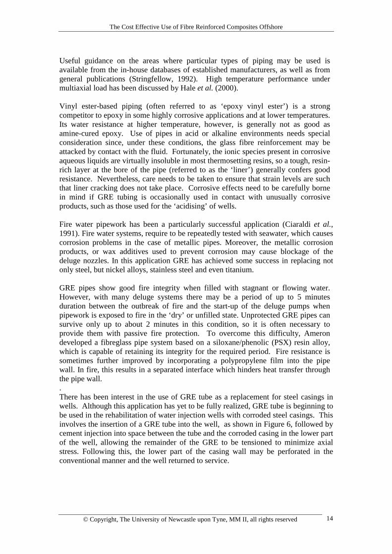
Useful guidance on the areas where particular types of piping may be used isavailable from the in-house databases of established manufacturers, as well as fromgeneral publications (Stringfellow, 1992). High temperature performance undermultiaxial load has been discussed by Hale et al. (2000). Vinyl ester-based piping (often referred to as ‘epoxy vinyl ester’) is a strongcompetitor to epoxy in some highly corrosive applications and at lower temperatures.Its water resistance at higher temperature, however, is generally not as good asamine-cured epoxy. Use of pipes in acid or alkaline environments needs specialconsideration since, under these conditions, the glass fibre reinforcement may beattacked by contact with the fluid. Fortunately, the ionic species present in corrosiveaqueous liquids are virtually insoluble in most thermosetting resins, so a tough, resin-rich layer at the bore of the pipe (referred to as the ‘liner’) generally confers goodresistance. Nevertheless, care needs to be taken to ensure that strain levels are suchthat liner cracking does not take place. Corrosive effects need to be carefully bornein mind if GRE tubing is occasionally used in contact with unusually corrosiveproducts, such as those used for the ‘acidising’ of wells. Fire water pipework has been a particularly successful application (Ciaraldi et al.,1991). Fire water systems, require to be repeatedly tested with seawater, which causescorrosion problems in the case of metallic pipes. Moreover, the metallic corrosionproducts, or wax additives used to prevent corrosion may cause blockage of thedeluge nozzles. In this application GRE has achieved some success in replacing notonly steel, but nickel alloys, stainless steel and even titanium. GRE pipes show good fire integrity when filled with stagnant or flowing water.However, with many deluge systems there may be a period of up to 5 minutesduration between the outbreak of fire and the start-up of the deluge pumps whenpipework is exposed to fire in the ‘dry’ or unfilled state. Unprotected GRE pipes cansurvive only up to about 2 minutes in this condition, so it is often necessary toprovide them with passive fire protection. To overcome this difficulty, Amerondeveloped a fibreglass pipe system based on a siloxane/phenolic (PSX) resin alloy,which is capable of retaining its integrity for the required period. Fire resistance issometimes further improved by incorporating a polypropylene film into the pipewall. In fire, this results in a separated interface which hinders heat transfer throughthe pipe wall. . There has been interest in the use of GRE tube as a replacement for steel casings inwells. Although this application has yet to be fully realized, GRE tube is beginning tobe used in the rehabilitation of water injection wells with corroded steel casings. Thisinvolves the insertion of a GRE tube into the well, as shown in Figure 6, followed bycement injection into space between the tube and the corroded casing in the lower partof the well, allowing the remainder of the GRE to be tensioned to minimize axialstress. Following this, the lower part of the casing wall may be perforated in theconventional manner and the well returned to service.
The Cost Effective Use of Fibre Reinforced Composites Offshore
© Copyright, The University of Newcastle upon Tyne, MM II, all rights reserved 15
Figure 6. Use of GRE pipe to replace severely corroded steel casing. Insertion of Ameron-Centronpipe into a water injection well (Courtesy Petroplastic SA).
The Cost Effective Use of Fibre Reinforced Composites Offshore
© Copyright, The University of Newcastle upon Tyne, MM II, all rights reserved 16
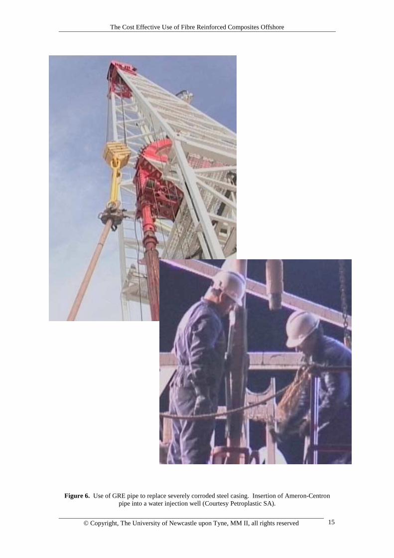
GRE caissons, Figure 7, are another interesting offshoot from GRE pipe technologyand would seem to be an ideal application for composites. Caissons are used whereservice fluids enter or leave the sea. Caissons are situated in the splash zone and aresubject to severe flexural fatigue due to wave loading. Steel caissons in thisapplication can be prone to both fatigue and corrosion problems.
Figure 7. GRE caisson (courtesy of Odebrecht SLP and Ameron BV) 3.2 Tanks and Vessels Composites have been used for some time for the manufacture of tanks for water anddiesel storage. There are effective and conservative codes that enable both tanks andpressure vessels to be designed for moderate pressures (Anisdahl et al., 1999,BS4994, 1987; ASME, 1992). Since a key feature of most pressure vessel codes forcomposites is the allowable strain, it is probable that future construction will placegreater emphasis on resin systems that display improved levels of elongation beforecracking occurs in the composite. The future is expected to bring more widespread use in tanks, as well as in vesselsoperating at higher pressures than at present. This will probably lead eventually toapplications in separators and other high pressure processing equipment wherethermal and corrosion requirements can be very demanding.
The Cost Effective Use of Fibre Reinforced Composites Offshore
© Copyright, The University of Newcastle upon Tyne, MM II, all rights reserved 17
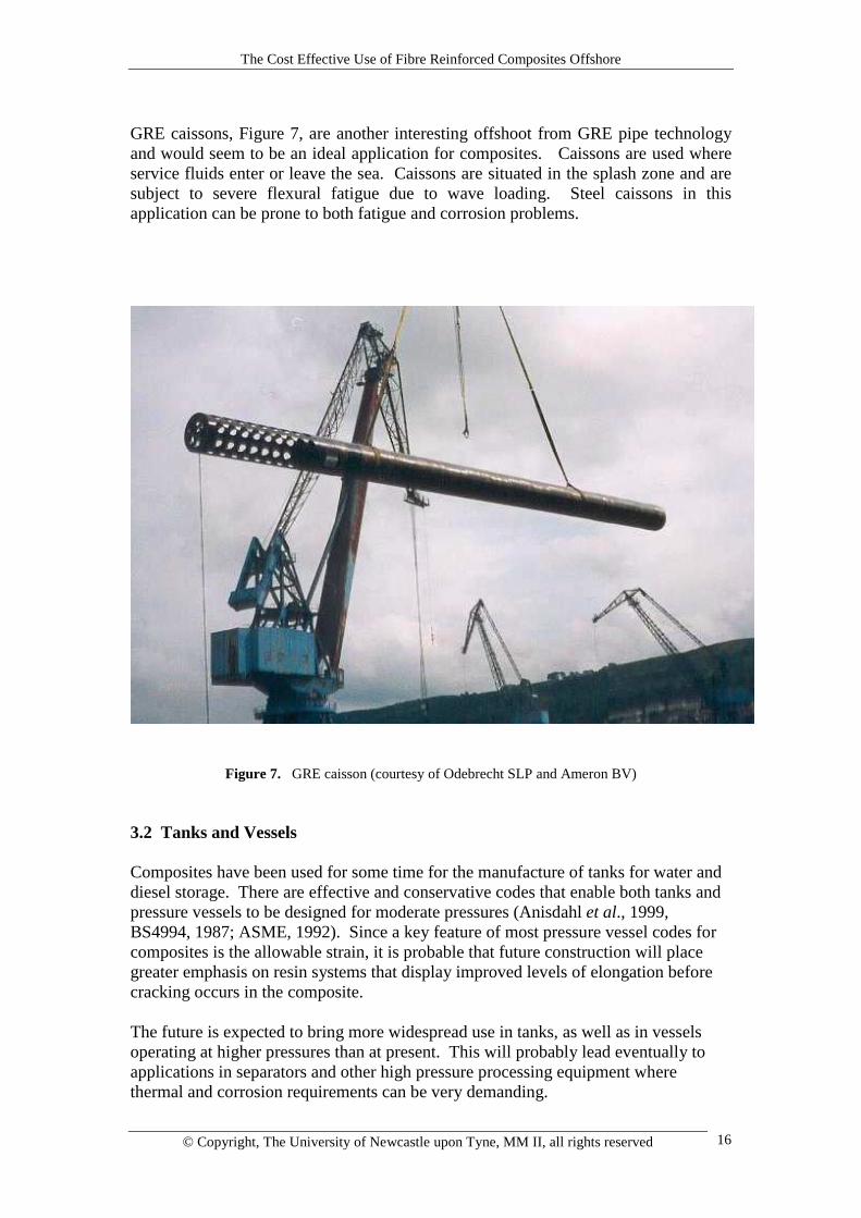
3.3 Flexible Thermosetting Tube Composite coil tube, as typified by ‘Fiberspar’ (Fowler, 1997; Fowler et al., 1998;Quigley et al., 1999) and ‘Compipe’ (Boye Hansen and Asdal, 1997; Asdal and BoyeHansen, 1999) is a new product, developed initially in response to the need for anon-metallic replacement for steel coil tubing. This product is used for high pressuredown-hole applications in which the tube is repeatedly transported on a drum,uncoiled and forced into the well. It is then removed, and re-coiled for further use.The life of the steel product is limited by low cycle fatigue associated with repeatedplastic deformations caused by the coiling and uncoiling. Another driving factor inthis development was the advent of long horizontal wells, which proved difficult forthe insertion of certain types of steel coil tube. Qualification of thermoset coil tube, of the type shown in Figure 8, has been carriedout in the USA for onshore application. The tube consists of a thermoplastic liner,over-wound with an epoxy-based structural thermosetting laminate. On coiling thematrix resin accommodates the flexural strain by cracking, but this does not damageeither the load-bearing capability of the fibres or the fluid containment capability ofthe thermoplastic liner. Flexible thermoset coil tubing can have a high pressurerating, typically 500 bar, but the product is currently restricted by manufacturingparameters to relatively small diameters, usually below 100mm. The reinforcementis typically E-glass, but carbon may also be employed, according to the applicationand economic factors. The liner material may also be tailored to the application, butwould normally be polyethylene, cross-linked polyethylene, nylon 11 or PVDF.
Figure 8. Flexible thermosetting composite tube (Courtesy of Fiberspar)
The Cost Effective Use of Fibre Reinforced Composites Offshore
© Copyright, The University of Newcastle upon Tyne, MM II, all rights reserved 18
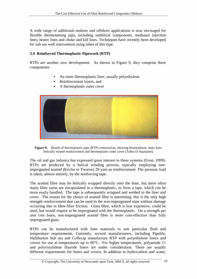
A wide range of additional onshore and offshore applications is now envisaged forflexible thermosetting pipe, including umbilical components, methanol injectionlines, heater lines and choke and kill lines. Techniques have recently been developedfor sub sea well intervention using tubes of this type. 3.4 Reinforced Thermoplastic Pipework (RTP) RTPs are another new development. As shown in Figure 9, they comprise threecomponents:
• An inner thermoplastic liner, usually polyethylene• Reinforcement layers, and• A thermoplastic outer cover
Figure 9. Details of thermoplastic pipe (RTP) construction, showing thermoplastic inner liner,helically wound reinforcement and thermoplastic outer cover (Tubes D-Aquitaine).
The oil and gas industry has expressed great interest in these systems (Frost, 1999).RTPs are produced by a helical winding process, typically employing non-impregnated aramid (Kevlar or Twaron) 29 yarn as reinforcement. The pressure loadis taken, almost entirely, by the reinforcing tape. The aramid fibre may be helically wrapped directly onto the liner, but more oftenmany fibre yarns are encapsulated in a thermoplastic, to form a tape, which can bemore easily handled. The tape is subsequently wrapped and welded to the liner andcover. The reason for the choice of aramid fibre is interesting: this is the only highstrength reinforcement that can be used in the non-impregnated state without damageoccurring due to fibre-fibre friction. Glass fibre, which is less expensive, could beused, but would require to be impregnated with the thermoplastic. On a strength perunit cost basis, non-impregnated aramid fibre is more cost-effective than fullyimpregnated glass. RTPs can be manufactured with liner materials to suit particular fluid andtemperature requirements. Currently, several manufacturers, including Pipelife,Halliburton Sub sea and Coflexip manufacture RTP with polyethylene liners andcovers for use at temperatures up to 60°C. For higher temperatures, polyamide 11and polyvinylidene fluoride liners are under consideration. There are usuallydifferent requirements for liners and covers. In addition to hydrocarbon and water,
The Cost Effective Use of Fibre Reinforced Composites Offshore
© Copyright, The University of Newcastle upon Tyne, MM II, all rights reserved 19
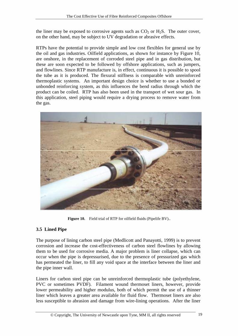
the liner may be exposed to corrosive agents such as CO2 or H2S. The outer cover,on the other hand, may be subject to UV degradation or abrasive effects. RTPs have the potential to provide simple and low cost flexibles for general use bythe oil and gas industries. Oilfield applications, as shown for instance by Figure 10,are onshore, in the replacement of corroded steel pipe and in gas distribution, butthese are soon expected to be followed by offshore applications, such as jumpers,and flowlines. Since RTP manufacture is, in effect, continuous it is possible to spoolthe tube as it is produced. The flexural stiffness is comparable with unreinforcedthermoplastic systems. An important design choice is whether to use a bonded orunbonded reinforcing system, as this influences the bend radius through which theproduct can be coiled. RTP has also been used in the transport of wet sour gas. Inthis application, steel piping would require a drying process to remove water fromthe gas.
Figure 10. Field trial of RTP for oilfield fluids (Pipelife BV)..
3.5 Lined Pipe The purpose of lining carbon steel pipe (Medlicott and Panayotti, 1999) is to preventcorrosion and increase the cost-effectiveness of carbon steel flowlines by allowingthem to be used for corrosive media. A major problem is liner collapse, which canoccur when the pipe is depressurised, due to the presence of pressurized gas whichhas permeated the liner, to fill any void space at the interface between the liner andthe pipe inner wall. Liners for carbon steel pipe can be unreinforced thermoplastic tube (polyethylene,PVC or sometimes PVDF). Filament wound thermoset liners, however, providelower permeability and higher modulus, both of which permit the use of a thinnerliner which leaves a greater area available for fluid flow. Thermoset liners are alsoless susceptible to abrasion and damage from wire-lining operations. After the liner
The Cost Effective Use of Fibre Reinforced Composites Offshore
© Copyright, The University of Newcastle upon Tyne, MM II, all rights reserved 20
has been placed within the pipe the space between the liner and the pipe wall isinjected with a cementitious or polymeric grout. 3.6 Rigid Risers Rigid riser systems are typically large diameter (250-550mm) high performancetubes which undergo complex loadings and which have pressure ratings of the orderof 1000 bar. They can employ a range of high strength and duplex steels, as well astitanium, assembled from short sections into considerable lengths. Rigid metallicrisers are widely used on all offshore platforms in both shallow and deep water.With increasing water depth, however, especially in excess of 1000 metres, bothplatform designs and the design of the risers begin to become highly weight-sensitive. The benefits of weight reduction through the introduction of composite risers havebeen known for some time, but the advent of deepwater is providing increasedimpetus for the use of these materials. The advantages include:
• Lower cost of added buoyancy (such as syntactic foam) requiredto reduce riser self-weight
• Reduction in riser external cross-section, leading to lower dragforces and reduced tension
• Reduction in the cost of tensioning equipment• On-going savings in topside weight
Development of composite rigid risers has been driven by a number of companies,including Conoco, Petrobras, Shell and Statoil. In the USA, several companies,including Lincoln Composites and Northrop Grumman have been involved in riserdevelopment. In Europe the Institut Français du Pétrole (IFP) has taken a leading rolein research on prototype riser systems (Sparks et al. 1995). Most proposed composite riser designs have certain common features:
• A metallic or elastomeric inner liner• near-axial reinforcement, often carbon fibre, to carry tensile and
bending loads• Near-hoop reinforcement, S-glass or carbon, to carry the pressure
load• A jointing system to allow many lengths to be put together
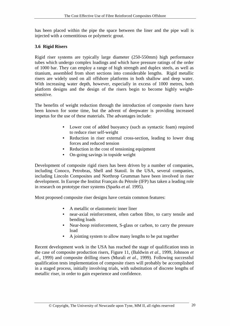
Recent development work in the USA has reached the stage of qualification tests inthe case of composite production risers, Figure 11, (Baldwin et al., 1999, Johnson etal., 1999) and composite drilling risers (Murali et al., 1999). Following successfulqualification tests implementation of composite risers will probably be accomplishedin a staged process, initially involving trials, with substitution of discrete lengths ofmetallic riser, in order to gain experience and confidence.
The Cost Effective Use of Fibre Reinforced Composites Offshore
© Copyright, The University of Newcastle upon Tyne, MM II, all rights reserved 21
Figure 11. Composite production riser specimens prepared for qualification testing (Lincoln Composites).
An interesting hybrid design for a drilling riser has been proposed by Odru et al1999. This involves the use of highly tensioned hoop-wound aramid fibres toincrease the hoop stress capability of a steel drilling riser, the axial load being borneby the steel tube. Full-scale application of composites in rigid risers is expected within the next decadeand, because of the scale of the product, is likely to require substantial increases,both in production capacity for carbon fibre and in manufacturing capability forfilament winding. 3.7 Flexible Risers These are high performance products, manufactured mainly by two companies,Coflexip and Wellstream and are used in many applications where flexible risers andflowlines are required (Kalman and Belcher, 1999, Do et al. 1999). The keycomponents of a high pressure flexible tube are:
• An inner stainless steel ‘carcass’, to prevent buckling underexternal compressive load
• A polymeric liner, to prevent corrosive product from coming intocontact with the outer components of the flexible
• Near-hoop, pressure resisting windings• Near-axial armour• An outer polymeric casing for external protection
The Cost Effective Use of Fibre Reinforced Composites Offshore
© Copyright, The University of Newcastle upon Tyne, MM II, all rights reserved 22
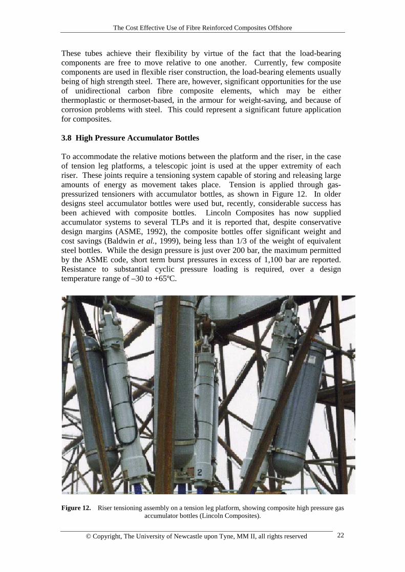
These tubes achieve their flexibility by virtue of the fact that the load-bearingcomponents are free to move relative to one another. Currently, few compositecomponents are used in flexible riser construction, the load-bearing elements usuallybeing of high strength steel. There are, however, significant opportunities for the useof unidirectional carbon fibre composite elements, which may be eitherthermoplastic or thermoset-based, in the armour for weight-saving, and because ofcorrosion problems with steel. This could represent a significant future applicationfor composites. 3.8 High Pressure Accumulator Bottles To accommodate the relative motions between the platform and the riser, in the caseof tension leg platforms, a telescopic joint is used at the upper extremity of eachriser. These joints require a tensioning system capable of storing and releasing largeamounts of energy as movement takes place. Tension is applied through gas-pressurized tensioners with accumulator bottles, as shown in Figure 12. In olderdesigns steel accumulator bottles were used but, recently, considerable success hasbeen achieved with composite bottles. Lincoln Composites has now suppliedaccumulator systems to several TLPs and it is reported that, despite conservativedesign margins (ASME, 1992), the composite bottles offer significant weight andcost savings (Baldwin et al., 1999), being less than 1/3 of the weight of equivalentsteel bottles. While the design pressure is just over 200 bar, the maximum permittedby the ASME code, short term burst pressures in excess of 1,100 bar are reported.Resistance to substantial cyclic pressure loading is required, over a designtemperature range of –30 to +65ºC.
Figure 12. Riser tensioning assembly on a tension leg platform, showing composite high pressure gas
accumulator bottles (Lincoln Composites).

The Cost Effective Use of Fibre Reinforced Composites Offshore
© Copyright, The University of Newcastle upon Tyne, MM II, all rights reserved 23
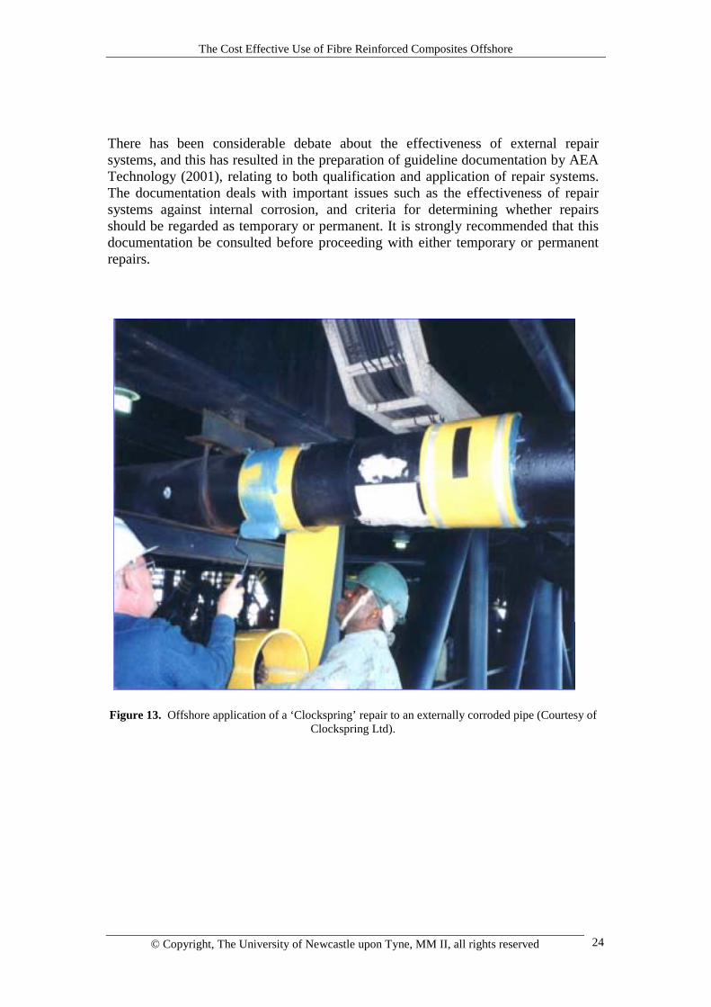
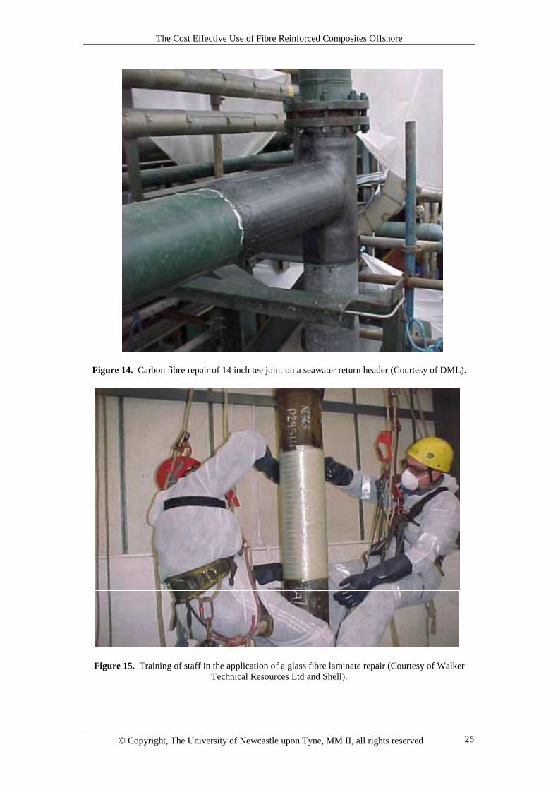
The design of the accumulators owes much to technology previously developed forgas tanks for natural gas vehicles. Injection moulded butt-welded polyethylene linersare employed, over which the load-bearing laminate layers are wound. Excellentfatigue resistance is claimed through the use of carbon fibre as the main load-bearingreinforcement. Damage tolerance and handling resistance is achieved through theuse of glass fibre to provide bulk and external protection. Over 120 bottles, up to2.6m long, 0.5m in diameter and weighing up to 250 kg each, are now in use onplatforms in the Gulf of Mexico. The same type of filament winding technology could eventually be applied to themanufacture of separators. The main problem here is the larger size of vessel and thehigh temperature of the well fluids. Nevertheless, developments are expected in thisarea, perhaps accelerated by in terst in seabed processing. 3.9 Repair of metallic tubulars The problem of corroded steel structures, especially pipework, is widespread in theoil and gas industry and there is considerable interest in temporary and permanentrehabilitation of such structures (Gibson, 2000, 2001, Mableson et al. 2000). Anumber of composite material solutions have been developed to address thisproblem. The majority of rehabilitation solutions for offshore use involve addingreinforcement to the exterior of the pipe or structure, to compensate for the loss ofsection thickness due to corrosion. The most successful of these is the ‘Clockspring’system, developed in the USA by the Gas Research Institute. This system is widelyused to restore hoop stress-bearing capability to externally corroded, or damagedpipework. Clockspring comprises a unidirectional glass fibre laminate, supplied inthe form in the form of a spiral helix. Figure 13 shows Clockspring being applied offshore to an externally corroded pipe.Application involves first cleaning the surface and filling external pits or damage, toallow stress to be transmitted from the pipe to the repair. Following this theClockspring laminate is wound around the pipe, while being coated with adhesive,which is allowed to cure. This is a highly effective means of permanently restoringhoop stress-bearing capability. Although several Clockspring repairs may be appliedadjacent to one another, the system does not provide axial or flexural stress bearingcapability. Its use is also difficult on bends, and limited mainly to cases where thecorrosion is external. Commercial systems are also available (Mableson et al. 2000) which allow theapplication of composite laminate with multidirectional fibre orientation, to permitrehabilitation of both axial and hoop stress-bearing capability. Companies whichsupply such systems include DML, Vosper Thornycroft and Walker TechnicalResources. Figure 14 shows the DML repair system, which comprises carbon fibrereinforcement, applied dry to the repair area, then impregnated using a vacuuminfusion technique. This is a derivative of a repair system originally developed forrepairing corroded structural members. Figure 15 shows employees being trained inthe use of a glass fibre-based laminate repair system.
The Cost Effective Use of Fibre Reinforced Composites Offshore
© Copyright, The University of Newcastle upon Tyne, MM II, all rights reserved 24
There has been considerable debate about the effectiveness of external repairsystems, and this has resulted in the preparation of guideline documentation by AEATechnology (2001), relating to both qualification and application of repair systems.The documentation deals with important issues such as the effectiveness of repairsystems against internal corrosion, and criteria for determining whether repairsshould be regarded as temporary or permanent. It is strongly recommended that thisdocumentation be consulted before proceeding with either temporary or permanentrepairs.
Figure 13. Offshore application of a ‘Clockspring’ repair to an externally corroded pipe (Courtesy of
Clockspring Ltd).
The Cost Effective Use of Fibre Reinforced Composites Offshore
© Copyright, The University of Newcastle upon Tyne, MM II, all rights reserved 25
Figure 14. Carbon fibre repair of 14 inch tee joint on a seawater return header (Courtesy of DML).
Figure 15. Training of staff in the application of a glass fibre laminate repair (Courtesy of Walker
Technical Resources Ltd and Shell).
The Cost Effective Use of Fibre Reinforced Composites Offshore
© Copyright, The University of Newcastle upon Tyne, MM II, all rights reserved 26
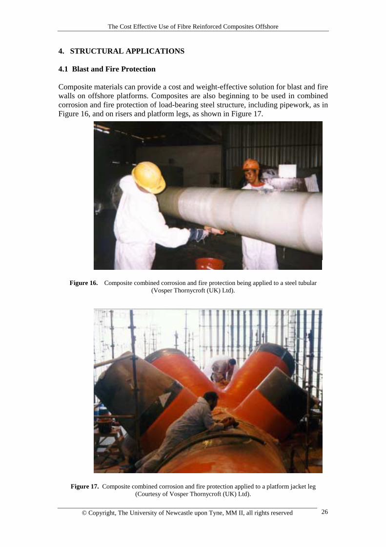
4. STRUCTURAL APPLICATIONS 4.1 Blast and Fire Protection Composite materials can provide a cost and weight-effective solution for blast and firewalls on offshore platforms. Composites are also beginning to be used in combinedcorrosion and fire protection of load-bearing steel structure, including pipework, as inFigure 16, and on risers and platform legs, as shown in Figure 17.
Figure 16. Composite combined corrosion and fire protection being applied to a steel tubular(Vosper Thornycroft (UK) Ltd).
Figure 17. Composite combined corrosion and fire protection applied to a platform jacket leg(Courtesy of Vosper Thornycroft (UK) Ltd).
The Cost Effective Use of Fibre Reinforced Composites Offshore
© Copyright, The University of Newcastle upon Tyne, MM II, all rights reserved 27
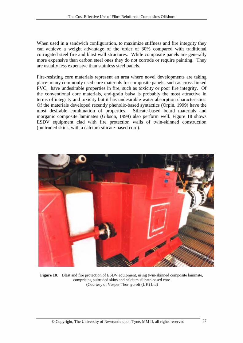
When used in a sandwich configuration, to maximize stiffness and fire integrity theycan achieve a weight advantage of the order of 30% compared with traditionalcorrugated steel fire and blast wall structures. While composite panels are generallymore expensive than carbon steel ones they do not corrode or require painting. Theyare usually less expensive than stainless steel panels. Fire-resisting core materials represent an area where novel developments are takingplace: many commonly used core materials for composite panels, such as cross-linkedPVC, have undesirable properties in fire, such as toxicity or poor fire integrity. Ofthe conventional core materials, end-grain balsa is probably the most attractive interms of integrity and toxicity but it has undesirable water absorption characteristics.Of the materials developed recently phenolic-based syntactics (Orpin, 1999) have themost desirable combination of properties. Silicate-based board materials andinorganic composite laminates (Gibson, 1999) also perform well. Figure 18 showsESDV equipment clad with fire protection walls of twin-skinned construction(pultruded skins, with a calcium silicate-based core).
Figure 18. Blast and fire protection of ESDV equipment, using twin-skinned composite laminate,
comprising pultruded skins and calcium silicate-based core (Courtesy of Vosper Thornycroft (UK) Ltd)
The Cost Effective Use of Fibre Reinforced Composites Offshore
© Copyright, The University of Newcastle upon Tyne, MM II, all rights reserved 28
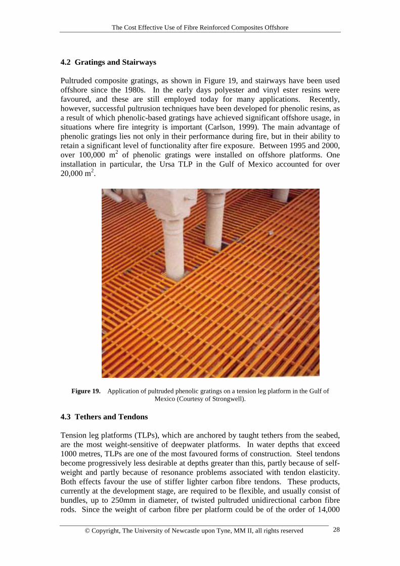
4.2 Gratings and Stairways Pultruded composite gratings, as shown in Figure 19, and stairways have been usedoffshore since the 1980s. In the early days polyester and vinyl ester resins werefavoured, and these are still employed today for many applications. Recently,however, successful pultrusion techniques have been developed for phenolic resins, asa result of which phenolic-based gratings have achieved significant offshore usage, insituations where fire integrity is important (Carlson, 1999). The main advantage ofphenolic gratings lies not only in their performance during fire, but in their ability toretain a significant level of functionality after fire exposure. Between 1995 and 2000,over 100,000 m2 of phenolic gratings were installed on offshore platforms. Oneinstallation in particular, the Ursa TLP in the Gulf of Mexico accounted for over20,000 m2.
Figure 19. Application of pultruded phenolic gratings on a tension leg platform in the Gulf of
Mexico (Courtesy of Strongwell). 4.3 Tethers and Tendons Tension leg platforms (TLPs), which are anchored by taught tethers from the seabed,are the most weight-sensitive of deepwater platforms. In water depths that exceed1000 metres, TLPs are one of the most favoured forms of construction. Steel tendonsbecome progressively less desirable at depths greater than this, partly because of self-weight and partly because of resonance problems associated with tendon elasticity.Both effects favour the use of stiffer lighter carbon fibre tendons. These products,currently at the development stage, are required to be flexible, and usually consist ofbundles, up to 250mm in diameter, of twisted pultruded unidirectional carbon fibrerods. Since the weight of carbon fibre per platform could be of the order of 14,000
The Cost Effective Use of Fibre Reinforced Composites Offshore
© Copyright, The University of Newcastle upon Tyne, MM II, all rights reserved 29
tonnes (Fischer and Salama, 1999) this represents a very large potential compositesmarket. The difficulty, as with a number of other potential applications for carbonfibre, relates to current annual production capacity for the material. 5. MAJOR LOAD-BEARING STRUCTURAL USE OF COMPOSITESOFFSHORE It has long been acknowledged that composite materials have the potential to be usedin major load-bearing structure offshore and it is probable that applications willevolve within the next few years. However, as mentioned at the beginning of thisreview, there have been a number of factors that have hindered this and it isworthwhile considering them. The problems which still remain relate to designerfamiliarity, industry infrastructure and the difficulty of scaling up traditionalcomposite fabrication processes so as to be able to make very large structures. A recent study by Maunsell Structural Plastics and Odebrecht SLP, involved the re-design of the topside of the Davy-Bessemer monopod platforms (shown in Figure 2)to make the maximum possible structural use of composites (Churchman et al., 1999;ARP, 2000). Following the decision to carry out a design study, there was extensivediscussion regarding the type of platform that would form the subject of the study.The small Davy-Bessemer platforms were chosen, at least partly, because their scalewould minimise the anticipated difficulties involving fabrication of large structures incomposites. The choice of a ‘not normally manned’ facility also simplified certainsafety requirements in regard to fire and accommodation.
Despite the relatively small scale of the structure, by offshore standards, one of theprincipal design difficulties was to determine a viable and cost-effective route for themanufacture of the main vertical and decking elements. For the decking, it wasdetermined that a structure of interlocking beams, that allowed some sharing of loadbetween transverse elements, would be the most favourable. Several options werediscussed and costings obtained from the industry before one particular structuraloption, the composite-wrapped pultruded cellular beam was chosen. One reason forthis choice was that, at the time of the project, no suitable pultruded section ofsufficient depth was available. It was recognised that, depending on the capabilities ofindividual manufacturers, there could be alternatives to the wrapped pultruded beamconcept- one of these being large custom-built structural elements fabricated usingRTM or vacuum infusion technology.
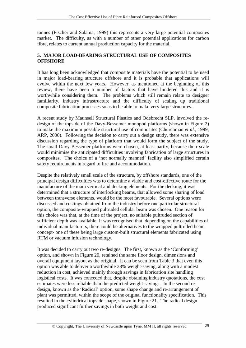
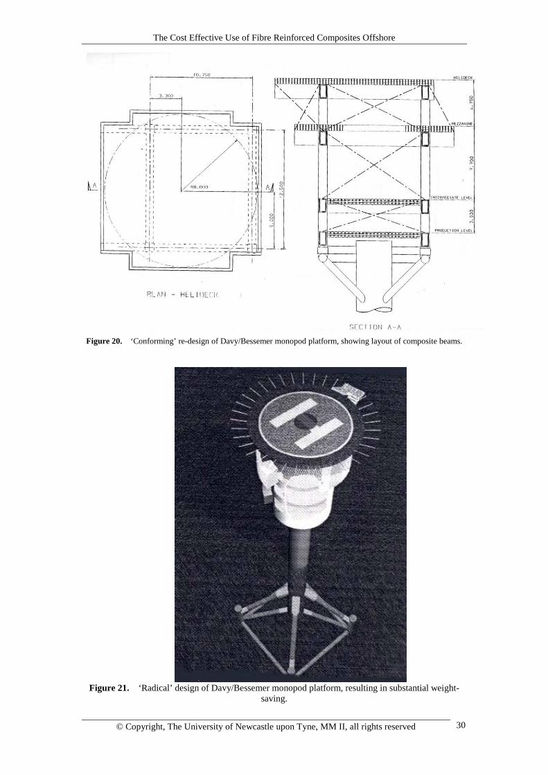
It was decided to carry out two re-designs. The first, known as the ‘Conforming’option, and shown in Figure 20, retained the same floor design, dimensions andoverall equipment layout as the original. It can be seen from Table 3 that even thisoption was able to deliver a worthwhile 38% weight-saving, along with a modestreduction in cost, achieved mainly through savings in fabrication site handlinglogistical costs. It was conceded that, despite obtaining industry quotations, the costestimates were less reliable than the predicted weight-savings. In the second re-design, known as the ‘Radical’ option, some shape change and re-arrangement ofplant was permitted, within the scope of the original functionality specification. Thisresulted in the cylindrical topside shape, shown in Figure 21. The radical designproduced significant further savings in both weight and cost.
The Cost Effective Use of Fibre Reinforced Composites Offshore
© Copyright, The University of Newcastle upon Tyne, MM II, all rights reserved 30
Figure 20. ‘Conforming’ re-design of Davy/Bessemer monopod platform, showing layout of composite beams.
Figure 21. ‘Radical’ design of Davy/Bessemer monopod platform, resulting in substantial weight-saving.
The Cost Effective Use of Fibre Reinforced Composites Offshore
© Copyright, The University of Newcastle upon Tyne, MM II, all rights reserved 31
The design exercise took into account all aspects of construction and deployment andresulted in some useful overall conclusions in addition to those in Table 3. It hadbeen anticipated, for example, that there might be a significant saving in the cost oflifting the topside into place. It turned out, however, that the choice of lift vessels wasgoverned more by availability than by payload range- the Davy and Bessemertopsides had been put in place by a vessel of considerably larger capacity than wasnecessitated by the lifting requirements alone.
The overall conclusions of the work were that composite topsides of significant sizewere a realistic option and that significant weight-savings could be achieved by thisroute. The real value of weight-savings would depend very largely on the type ofplatform. The other areas where savings were to be expected were in on-site activities(during build) and of course through-life costs.
Table 3 Weight and cost comparisons for the re-design of the Davy-Bessemer platform
topsides in composite material.
Characteristic Baselinesteel
structure.
Composite ‘Conforming’solution.
Composite ‘Radical’solution
Weight &cost
Saving Weight &cost
Saving
Weight 187 t. 116 t. 38% 84 t. 55%Cost £992,000 £920,000 7% £736,000 26%
5.1 Designers and Fabricators Offshore platforms are always constructed to a tight schedule and budget. Designersand contractors unfamiliar with composites have, until recently been reluctant tospecify a new material that involves different design and working practices. The mostinteresting pioneering developments, such as the widespread use of composites on theAmoco Davy and Bessemer platforms, have often been led initially by an oil companyacting as a champion for the material. The example set by a small number of oilcompanies, as described for instance by Houghton (1999) in this area is nowbeginning to be followed by several contractors who are gaining familiarity withcomposites and training their staff in the use of these materials. In piping and vessel applications designers have been fairly well served by compositepressure vessel design codes such as (BS4994 (1987) and ASME (1992)) as well as arange of API specifications for composite tubing, and the more recent UKOOAGuideline for composite piping (United Kingdom Offshore Operators Association,1994) and ISO documentation (ISO 2000). This probably explains the successfulpenetration of composites in the vessel and piping areas. Until recently, however, itcould be claimed by potential users, with some justification, that there were no designcodes that readily permitted the use of composites in load-bearing structure. Thissituation is now changing, with the advent of limit state codes such as the Eurocodefor Composites (1994), and, more recently, the DNV Design Guideline for Designwith Composites (Det Norske Veritas, 2000).
The Cost Effective Use of Fibre Reinforced Composites Offshore
© Copyright, The University of Newcastle upon Tyne, MM II, all rights reserved 32
5.2 Composites Industry Infrastructure The composites industry, by and large, consists of small to medium sized enterprisesoperating a wide variety of processes (Sims, 2001). While this results in a usefulflexibility of approach and a flair for innovation, these factors prove disadvantageouswhen it comes to dealing with the offshore industry and its supply chain. It is nocoincidence that the companies that have achieved greatest success in supplying theoffshore industry tend to be larger organisations with existing contacts with designhouses and contractors. The answer to these problems must lie in improved alliancesbetween suppliers, or groups of suppliers and contractors. There are also some potential problems with capacity. Some of the more promisingapplications for offshore products, including risers and tethers, as mentioned above,involve volumes that would require a step change in production capacity, not only forcomposite manufacture, but also in the supply of carbon fibre. There is evidence thatthe carbon fibre industry, stimulated by growth in several engineering areas, is on thethreshold of such a change. One encouraging development is the improvingavailability of new low cost carbon fibre products. 5.3 Scale-up of Fabrication Processes Of the many processes that can be used for fabricating composite parts, only a few arecapable of being scaled-up to produce structures of the size needed for structuralitems on offshore platforms. These processes are:
• Contact moulding (or hand-laminating)• Resin infusion processes• Pultrusion, and• Filament winding
Currently, the largest composite structures are glass fibre minehunter vessels, up to 55metres in length. These vessels clearly demonstrate the problems of designing andmaking large composite structures, most notably the difficulties of designing effectivejoints and of achieving the necessary structural stiffness with glass fibre. They alsodemonstrate the solutions to these problems through the development of special jointconfigurations and the use of twin-skinned or stiffened skin structures. Although themain process to date has been contact moulding, environmental regulations and theneed for improved quality of construction have led to the use of resin infusionprocesses (as typified by the proprietary SCRIMP or Seeman Composites ResinInfusion Moulding Process). Ship builders are making increasing use of processes ofthis type.
The move towards resin infusion is further demonstrated by the recent development inSweden of carbon based-based corvette craft up to 70 metres in length with stealthcapability (Gibson, 2001). These craft employ resin infusion throughout their hullstructure in conjunction with carbon vinyl/vinyl ester and sandwich construction toachieve high stiffness. Clearly this type of construction would be viable for load-bearing structure offshore.
The Cost Effective Use of Fibre Reinforced Composites Offshore
© Copyright, The University of Newcastle upon Tyne, MM II, all rights reserved 33
The key problem in the construction of large area decks for topside structures is theachievement of the required degree of stiffness. The depth of section required for asandwich construction deck is currently greater than can easily be achieved usingfoam-cored sandwich, and sandwich cores may not, in general be capable of resistingthe very large direct and shear loads involved with such a deck.
An alternative approach to deck design has been considered in the AdvancedResearch Partnership Composites Offshore programme (ARP, 2000). Instead ofsandwich construction, it was found that a linked assembly of pultruded cellularelements could provide the required depth and stiffness of section. Added stiffeningcould be achieved through transverse connections between the cellular elements.
One promising recent development is the deep section pultruded box beam that hasbeen achieved recently by Strongwell (Witcher, 1999).
6 PROPERTIES OF COMPOSITES RELEVANT TO OFFSHORE APPLICATIONS
6.1 Environmental and Fatigue Behaviour
Effective structural use of composites offshore requires an accurate knowledge oftheir behaviour under repeated loading and their response to marine environments.Fatigue performance has been reviewed recently by Konur and Matthews (1989) and,in relation to marine applications, by Scholte (1994). Given the need for acceleratedgeneration of data on new resin and fibre systems, Kotsikos et al. (2000) undertook aseries of studies on relevant composite systems, both dry and after an acceleratedconditioning programme in seawater, the aim being to accurately define the strainlimits for design.
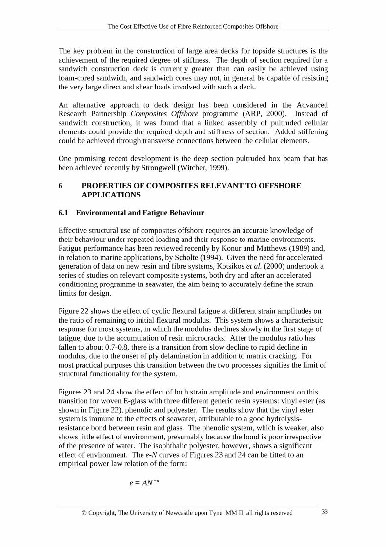
Figure 22 shows the effect of cyclic flexural fatigue at different strain amplitudes onthe ratio of remaining to initial flexural modulus. This system shows a characteristicresponse for most systems, in which the modulus declines slowly in the first stage offatigue, due to the accumulation of resin microcracks. After the modulus ratio hasfallen to about 0.7-0.8, there is a transition from slow decline to rapid decline inmodulus, due to the onset of ply delamination in addition to matrix cracking. Formost practical purposes this transition between the two processes signifies the limit ofstructural functionality for the system.
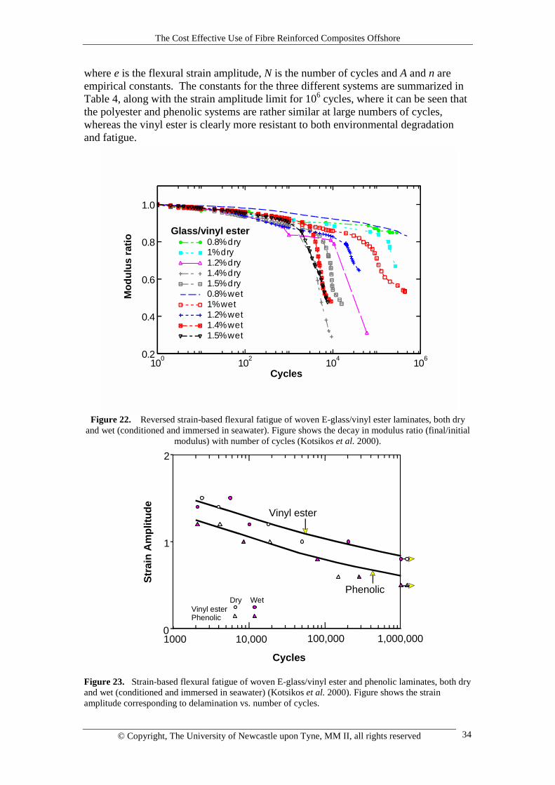
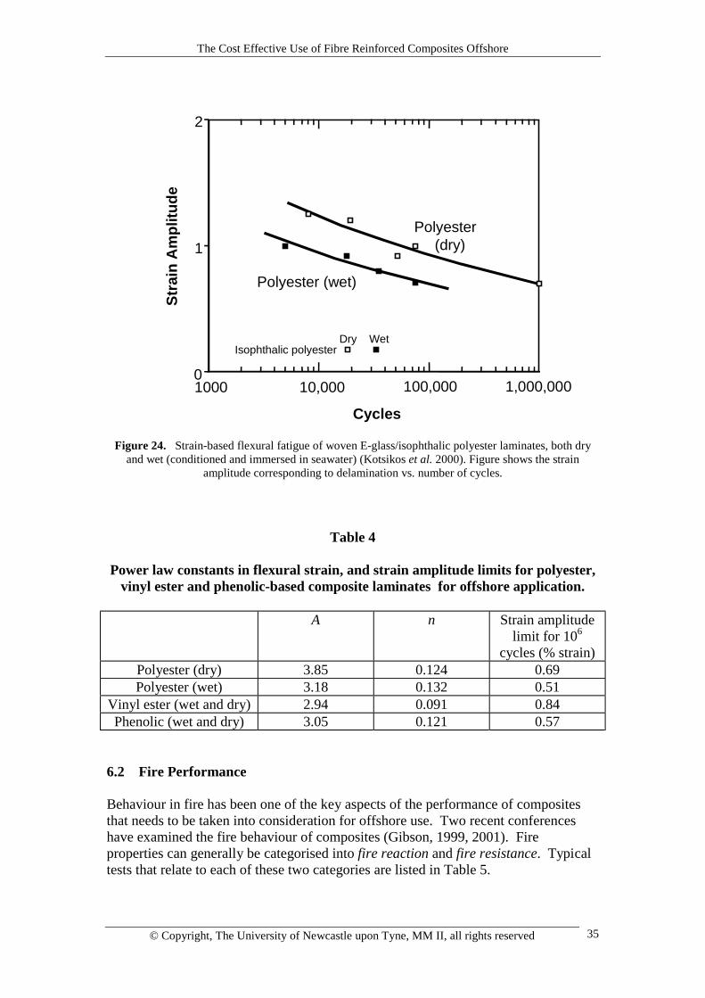
Figures 23 and 24 show the effect of both strain amplitude and environment on thistransition for woven E-glass with three different generic resin systems: vinyl ester (asshown in Figure 22), phenolic and polyester. The results show that the vinyl estersystem is immune to the effects of seawater, attributable to a good hydrolysis-resistance bond between resin and glass. The phenolic system, which is weaker, alsoshows little effect of environment, presumably because the bond is poor irrespectiveof the presence of water. The isophthalic polyester, however, shows a significanteffect of environment. The e-N curves of Figures 23 and 24 can be fitted to anempirical power law relation of the form:
e AN n= −
The Cost Effective Use of Fibre Reinforced Composites Offshore
© Copyright, The University of Newcastle upon Tyne, MM II, all rights reserved 34
where e is the flexural strain amplitude, N is the number of cycles and A and n areempirical constants. The constants for the three different systems are summarized inTable 4, along with the strain amplitude limit for 106 cycles, where it can be seen thatthe polyester and phenolic systems are rather similar at large numbers of cycles,whereas the vinyl ester is clearly more resistant to both environmental degradationand fatigue.
Figure 22. Reversed strain-based flexural fatigue of woven E-glass/vinyl ester laminates, both dryand wet (conditioned and immersed in seawater). Figure shows the decay in modulus ratio (final/initial
modulus) with number of cycles (Kotsikos et al. 2000).
Figure 23. Strain-based flexural fatigue of woven E-glass/vinyl ester and phenolic laminates, both dryand wet (conditioned and immersed in seawater) (Kotsikos et al. 2000). Figure shows the strainamplitude corresponding to delamination vs. number of cycles.
0.2
0.4
0.6
0.8
1.0
100 102 104 106
0.8% dry1% dry1.2% dry1.4% dry1.5% dry0.8% wet1% wet1.2% wet1.4% wet1.5% wet
Cycles
Mod
ulus
ratio
Glass/vinyl ester
Cycles
0
1
2
1000 10,000 100,000 1,000,000
Vinyl ester
Phenolic
Stra
in A
mpl
itude
Vinyl esterPhenolic
Dry Wet
The Cost Effective Use of Fibre Reinforced Composites Offshore
© Copyright, The University of Newcastle upon Tyne, MM II, all rights reserved 35
Figure 24. Strain-based flexural fatigue of woven E-glass/isophthalic polyester laminates, both dryand wet (conditioned and immersed in seawater) (Kotsikos et al. 2000). Figure shows the strain
amplitude corresponding to delamination vs. number of cycles.
Table 4
Power law constants in flexural strain, and strain amplitude limits for polyester,vinyl ester and phenolic-based composite laminates for offshore application.
A n Strain amplitudelimit for 106
cycles (% strain)Polyester (dry) 3.85 0.124 0.69Polyester (wet) 3.18 0.132 0.51
Vinyl ester (wet and dry) 2.94 0.091 0.84Phenolic (wet and dry) 3.05 0.121 0.57
6.2 Fire Performance
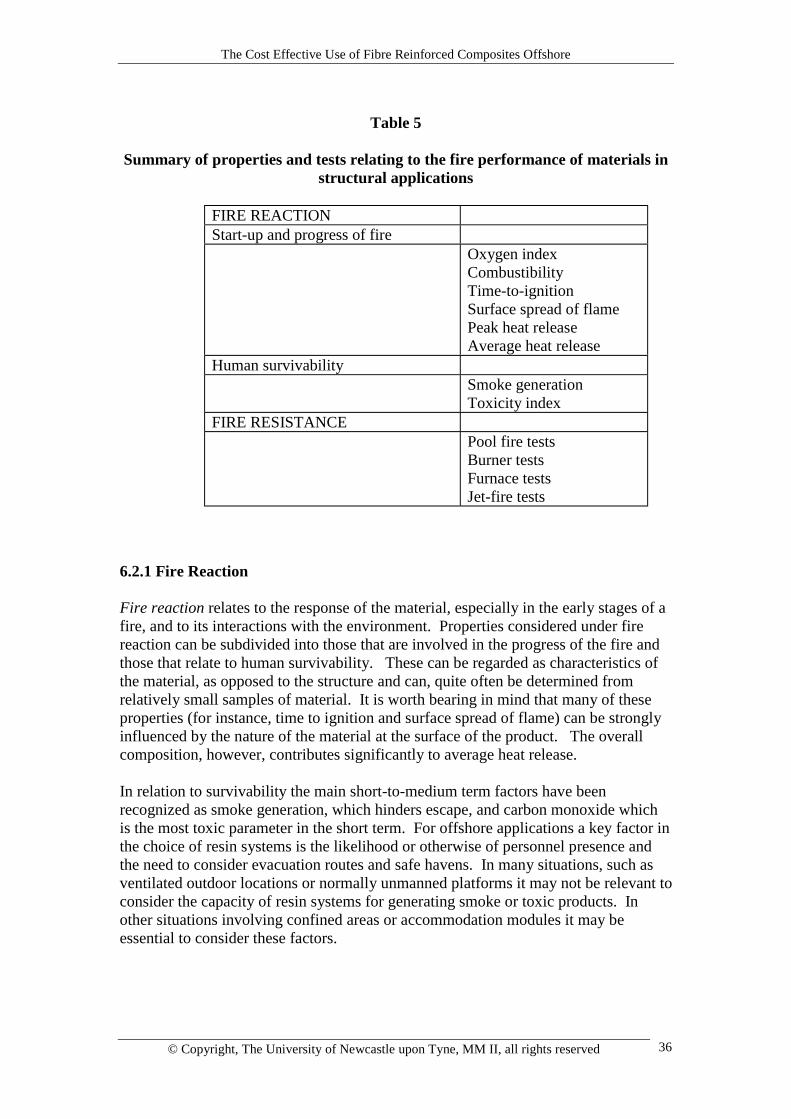
Behaviour in fire has been one of the key aspects of the performance of compositesthat needs to be taken into consideration for offshore use. Two recent conferenceshave examined the fire behaviour of composites (Gibson, 1999, 2001). Fireproperties can generally be categorised into fire reaction and fire resistance. Typicaltests that relate to each of these two categories are listed in Table 5.
0
1
2
1000 10,000 100,000 1,000,000
Polyester (wet)
Polyester (dry)
Cycles
Stra
in A
mpl
itude
Isophthalic polyesterDry Wet
The Cost Effective Use of Fibre Reinforced Composites Offshore
© Copyright, The University of Newcastle upon Tyne, MM II, all rights reserved 36
Table 5
Summary of properties and tests relating to the fire performance of materials instructural applications
FIRE REACTIONStart-up and progress of fire
Oxygen indexCombustibilityTime-to-ignitionSurface spread of flamePeak heat releaseAverage heat release
Human survivabilitySmoke generationToxicity index
FIRE RESISTANCEPool fire testsBurner testsFurnace testsJet-fire tests
6.2.1 Fire Reaction
Fire reaction relates to the response of the material, especially in the early stages of afire, and to its interactions with the environment. Properties considered under firereaction can be subdivided into those that are involved in the progress of the fire andthose that relate to human survivability. These can be regarded as characteristics ofthe material, as opposed to the structure and can, quite often be determined fromrelatively small samples of material. It is worth bearing in mind that many of theseproperties (for instance, time to ignition and surface spread of flame) can be stronglyinfluenced by the nature of the material at the surface of the product. The overallcomposition, however, contributes significantly to average heat release.
In relation to survivability the main short-to-medium term factors have beenrecognized as smoke generation, which hinders escape, and carbon monoxide whichis the most toxic parameter in the short term. For offshore applications a key factor inthe choice of resin systems is the likelihood or otherwise of personnel presence andthe need to consider evacuation routes and safe havens. In many situations, such asventilated outdoor locations or normally unmanned platforms it may not be relevant toconsider the capacity of resin systems for generating smoke or toxic products. Inother situations involving confined areas or accommodation modules it may beessential to consider these factors.
The Cost Effective Use of Fibre Reinforced Composites Offshore
© Copyright, The University of Newcastle upon Tyne, MM II, all rights reserved 37
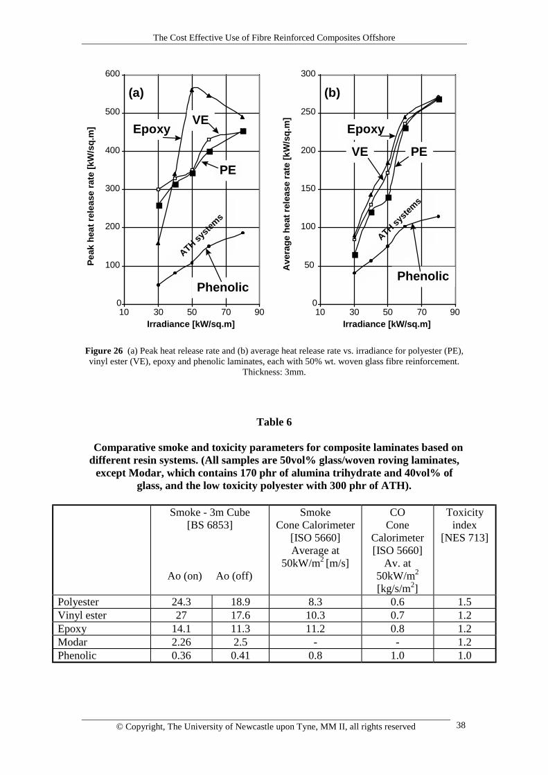
Typical data relating to the generation of smoke and toxic products are shown inTable 6. Here, it can be seen that the systems with very low smoke generation arephenolic and Modar (modified acrylic resin). These are probably the only systems thatmight be permitted in areas where personnel might be present with limited means ofescape. The Modar system derives its low toxicity from the addition of aluminatrihydrate additive. The other composite systems, polyester, vinyl ester and epoxy allhave higher smoke and toxicity levels. It is worth noting that phenolic-basedcomposites, which are generally well-regarded in terms of smoke emission, do notgenerally score highly in terms of toxicity because of CO generation.
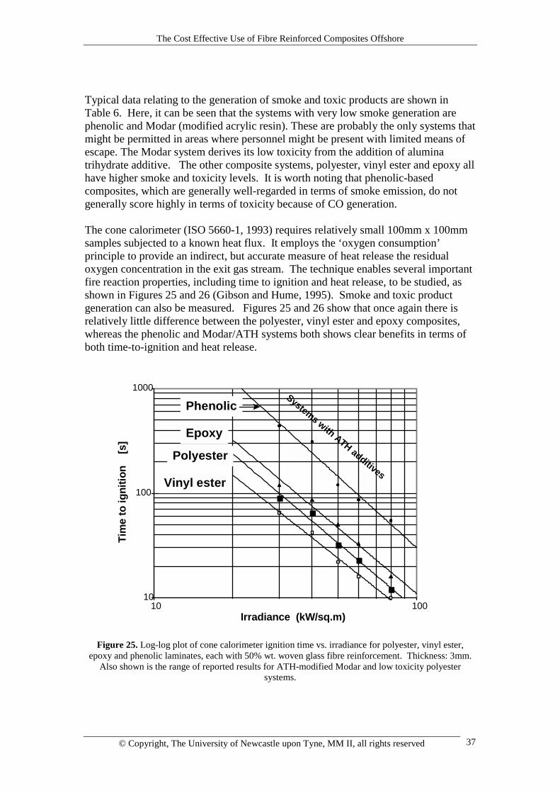
The cone calorimeter (ISO 5660-1, 1993) requires relatively small 100mm x 100mmsamples subjected to a known heat flux. It employs the ‘oxygen consumption’principle to provide an indirect, but accurate measure of heat release the residualoxygen concentration in the exit gas stream. The technique enables several importantfire reaction properties, including time to ignition and heat release, to be studied, asshown in Figures 25 and 26 (Gibson and Hume, 1995). Smoke and toxic productgeneration can also be measured. Figures 25 and 26 show that once again there isrelatively little difference between the polyester, vinyl ester and epoxy composites,whereas the phenolic and Modar/ATH systems both shows clear benefits in terms ofboth time-to-ignition and heat release.
10
100
1000
10 100Irradiance (kW/sq.m)
Tim
e to
igni
tion
[s
]
Phenolic
Epoxy
Polyester
Vinyl ester
Systems with ATH additives
Figure 25. Log-log plot of cone calorimeter ignition time vs. irradiance for polyester, vinyl ester,epoxy and phenolic laminates, each with 50% wt. woven glass fibre reinforcement. Thickness: 3mm.
Also shown is the range of reported results for ATH-modified Modar and low toxicity polyestersystems.
The Cost Effective Use of Fibre Reinforced Composites Offshore
© Copyright, The University of Newcastle upon Tyne, MM II, all rights reserved 38
0
100
200
300
400
500
600
10 30 50 70 90Irradiance [kW/sq.m]
Peak
hea
t rel
ease
rate
[kW
/sq.
m]
0
50
100
150
200
250
300
10 30 50 70 90Irradiance [kW/sq.m]
Ave
rage
hea
t rel
ease
rate
[kW
/sq.
m]
(a) (b)
EpoxyEpoxyVE
VE PEPE
PhenolicPhenolic
ATH syste
ms
ATH syste
ms
Figure 26 (a) Peak heat release rate and (b) average heat release rate vs. irradiance for polyester (PE),vinyl ester (VE), epoxy and phenolic laminates, each with 50% wt. woven glass fibre reinforcement.
Thickness: 3mm.
Table 6
Comparative smoke and toxicity parameters for composite laminates based ondifferent resin systems. (All samples are 50vol% glass/woven roving laminates,
except Modar, which contains 170 phr of alumina trihydrate and 40vol% ofglass, and the low toxicity polyester with 300 phr of ATH).
Smoke - 3m Cube[BS 6853]
Ao (on) Ao (off)
SmokeCone Calorimeter
[ISO 5660]Average at
50kW/m2 [m/s]
COCone
Calorimeter[ISO 5660]
Av. at50kW/m2
[kg/s/m2]
Toxicityindex
[NES 713]
Polyester 24.3 18.9 8.3 0.6 1.5Vinyl ester 27 17.6 10.3 0.7 1.2Epoxy 14.1 11.3 11.2 0.8 1.2Modar 2.26 2.5 - - 1.2Phenolic 0.36 0.41 0.8 1.0 1.0
The Cost Effective Use of Fibre Reinforced Composites Offshore
© Copyright, The University of Newcastle upon Tyne, MM II, all rights reserved 39
6.2.2 Fire Resistance
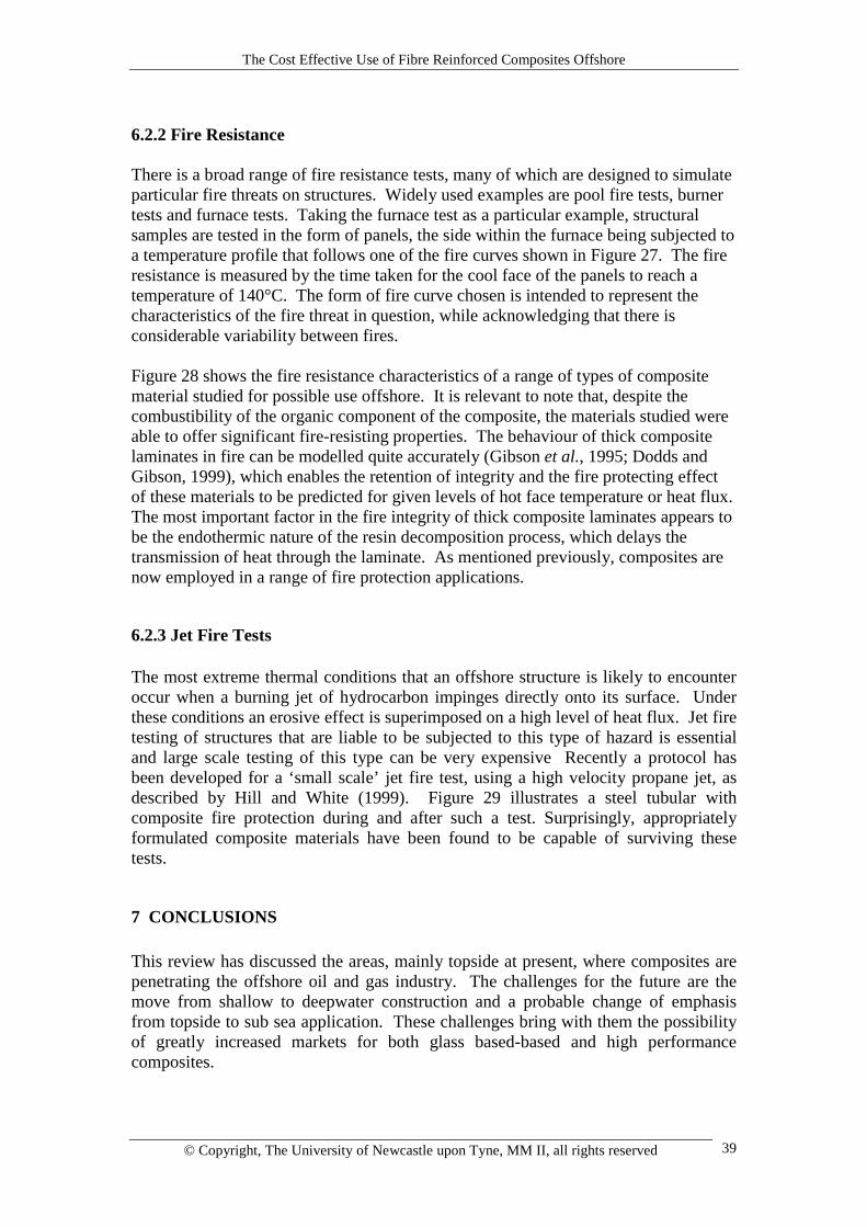
There is a broad range of fire resistance tests, many of which are designed to simulateparticular fire threats on structures. Widely used examples are pool fire tests, burnertests and furnace tests. Taking the furnace test as a particular example, structuralsamples are tested in the form of panels, the side within the furnace being subjected toa temperature profile that follows one of the fire curves shown in Figure 27. The fireresistance is measured by the time taken for the cool face of the panels to reach atemperature of 140°C. The form of fire curve chosen is intended to represent thecharacteristics of the fire threat in question, while acknowledging that there isconsiderable variability between fires.
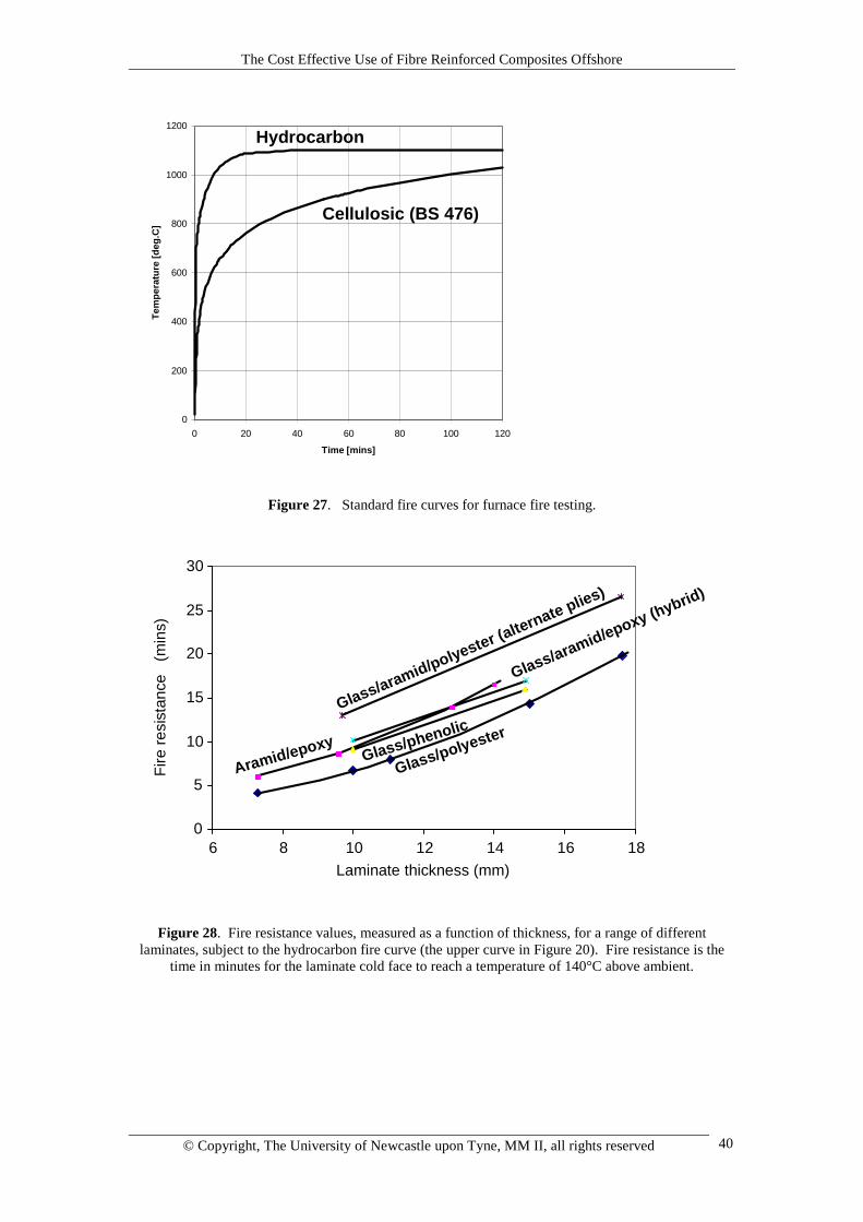
Figure 28 shows the fire resistance characteristics of a range of types of compositematerial studied for possible use offshore. It is relevant to note that, despite thecombustibility of the organic component of the composite, the materials studied wereable to offer significant fire-resisting properties. The behaviour of thick compositelaminates in fire can be modelled quite accurately (Gibson et al., 1995; Dodds andGibson, 1999), which enables the retention of integrity and the fire protecting effectof these materials to be predicted for given levels of hot face temperature or heat flux.The most important factor in the fire integrity of thick composite laminates appears tobe the endothermic nature of the resin decomposition process, which delays thetransmission of heat through the laminate. As mentioned previously, composites arenow employed in a range of fire protection applications.
6.2.3 Jet Fire Tests
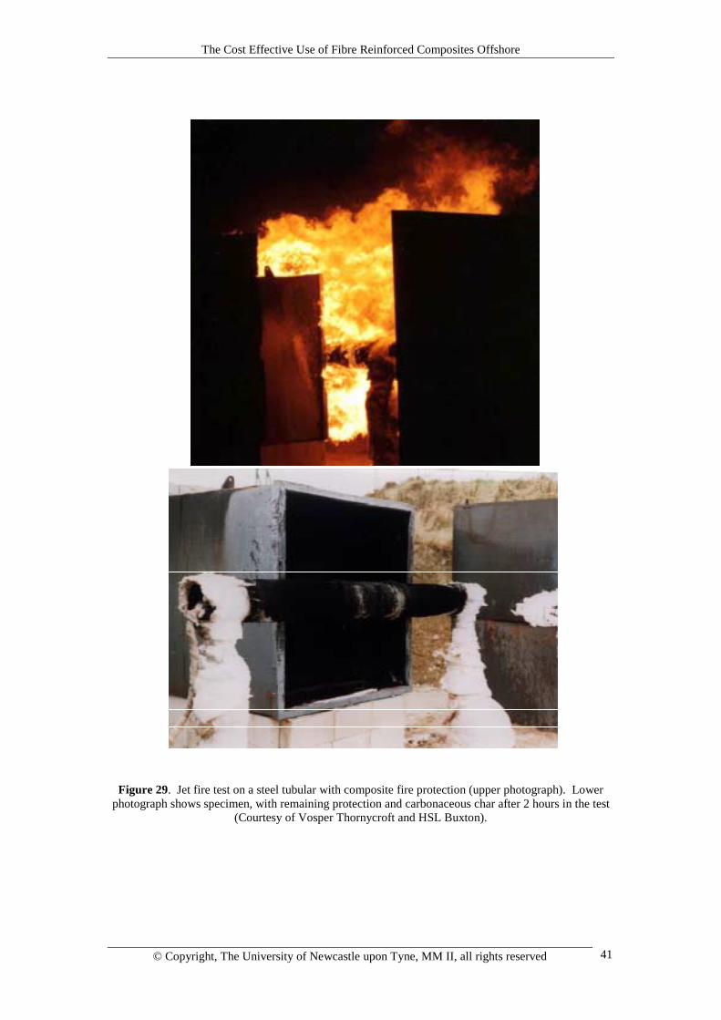
The most extreme thermal conditions that an offshore structure is likely to encounteroccur when a burning jet of hydrocarbon impinges directly onto its surface. Underthese conditions an erosive effect is superimposed on a high level of heat flux. Jet firetesting of structures that are liable to be subjected to this type of hazard is essentialand large scale testing of this type can be very expensive Recently a protocol hasbeen developed for a ‘small scale’ jet fire test, using a high velocity propane jet, asdescribed by Hill and White (1999). Figure 29 illustrates a steel tubular withcomposite fire protection during and after such a test. Surprisingly, appropriatelyformulated composite materials have been found to be capable of surviving thesetests.
7 CONCLUSIONS
This review has discussed the areas, mainly topside at present, where composites arepenetrating the offshore oil and gas industry. The challenges for the future are themove from shallow to deepwater construction and a probable change of emphasisfrom topside to sub sea application. These challenges bring with them the possibilityof greatly increased markets for both glass based-based and high performancecomposites.
The Cost Effective Use of Fibre Reinforced Composites Offshore
© Copyright, The University of Newcastle upon Tyne, MM II, all rights reserved 40
0
200
400
600
800
1000
1200
0 20 40 60 80 100 120
Time [mins]
Tem
pera
ture
[deg
.C]
Hydrocarbon
Cellulosic (BS 476)
Figure 27. Standard fire curves for furnace fire testing.
0
5
10
15
20
25
30
6 8 10 12 14 16 18
Glass/polyesterGlass/phenolic
Aramid/epoxy
Glass/aramid/polyester (alternate plies)
Glass/aramid/epoxy (hybrid)
Laminate thickness (mm)
Fire
resi
stan
ce
(min
s)
Figure 28. Fire resistance values, measured as a function of thickness, for a range of differentlaminates, subject to the hydrocarbon fire curve (the upper curve in Figure 20). Fire resistance is the
time in minutes for the laminate cold face to reach a temperature of 140°C above ambient.
The Cost Effective Use of Fibre Reinforced Composites Offshore
© Copyright, The University of Newcastle upon Tyne, MM II, all rights reserved 41
Figure 29. Jet fire test on a steel tubular with composite fire protection (upper photograph). Lowerphotograph shows specimen, with remaining protection and carbonaceous char after 2 hours in the test
(Courtesy of Vosper Thornycroft and HSL Buxton).
The Cost Effective Use of Fibre Reinforced Composites Offshore
© Copyright, The University of Newcastle upon Tyne, MM II, all rights reserved 42
8. REFERENCES
AEA Technology, Guideline for the Application of Composite Repair Systems, 2001.
L. Anisdahl, D.T. Wang and R. Stokke, in Composite Materials for OffshoreOperations-2 (CMOO-2)’, eds. S.S. Wang, J.G. Williams and K.H. Lo, AmericanBureau of Shipping, Houston TX 77060, 1999, ISBN 0-943870-01-1. pp261-274.
ARP, Final Report on The Cost-Effective Use of Fibre Reinforced CompositesOffshore, Phase 4. 2000, Advanced Research Partnership, UMIST, P.O.Box 88,Sackville Street, Manchester M60 1QD
B. Asdal and A. Boye Hansen, in Composite Materials for Offshore Operations-2(CMOO-2)’, eds. S.S. Wang, J.G. Williams and K.H. Lo, American Bureau ofShipping, Houston TX 77060, 1999, ISBN 0-943870-01-1. pp319-328.
ASME Boiler and Pressure Vessel Code, Section X: Fibre Reinforced PlasticPressure Vessels, The American Society of Mechanical Engineers, 1992.
ASTM 2992-96e1, Standard Practice for Obtaining Hydrostatic or PressureDesign Basics for “Fiberglass” (Glass-Fiber-Reinforced Thermosetting-Resin)Pipe and Fittings.
D. Baldwin, N. Newhouse and K.H. Lo, in Composite Materials for OffshoreOperations-2 (CMOO-2)’, eds. S.S. Wang, J.G. Williams and K.H. Lo, AmericanBureau of Shipping, Houston TX 77060, 1999, ISBN 0-943870-01-1. pp115-128.
D. Baldwin, N. Newhouse and K.H. Lo, in Composite Materials for OffshoreOperations-2 (CMOO-2)’, eds. S.S. Wang, J.G. Williams and K.H. Lo, AmericanBureau of Shipping, Houston TX 77060, 1999, ISBN 0-943870-01-1. pp275-286.
F. Botros, J. Williams and E. Coyle, ‘Offshore Technology Conference’, OTC8500, 1997.
A. Boye Hansen and B. Asdal, OTC8436, Offshore Technology Conference,Houston 5-8 May, 1997.
BS 4994: Design and Construction of Vessels and Tanks in Reinforced Plastics,British Standards Institution, London UK, 1987.
T. Carlson, Product data on pultruded phenolic gratings, Strongwell, 1999; also inproceedings of Composites in Fire Conference, ed. A.G. Gibson, University ofNewcastle upon Tyne, 15-16 September 1999.
A.E. Churchman, J.M.C. Cadei and R. Shirandami, in Composite Materials forOffshore Operations-2 (CMOO-2)’, eds. S.S. Wang, J.G. Williams and K.H. Lo,
The Cost Effective Use of Fibre Reinforced Composites Offshore
© Copyright, The University of Newcastle upon Tyne, MM II, all rights reserved 43
American Bureau of Shipping, Houston TX 77060, 1999, ISBN 0-943870-01-1.pp447-460.
S Ciaraldi, J D Alkire and G Huntoon, Fiberglas Firewater Systems for OffshorePlatforms, Paper OTC 6926, 23rd Annual Offshore Technology Conference,Houston TX, May 6-9 1991.
‘Composite Materials for Offshore Operations: Proceedings of the FirstInternational Workshop’, Houston TX 26-28th October, 1993. NIST SpecialPublication 887.
M.J. Cowling et al, Composites A, 2000.
J. Croquette, Potential Applications of Composites Offshore, Proc. Of CompositeMaterials in the Petroleum Industry, Institut Français du Pétrole, November 3-4,1994
DNV Joint Industry Project on FRP Design Guidelines, Det Norske Veritas AS,2000.
A.T. Do, O. Beaudoin, P. Odru and F. Grosjean, in Composite Materials forOffshore Operations-2 (CMOO-2)’, eds. S.S. Wang, J.G. Williams and K.H. Lo,American Bureau of Shipping, Houston TX 77060, 1999, ISBN 0-943870-01-1.pp141-150.
N. Dodds and A.G. Gibson, in Composite Materials for Offshore Operations-2(CMOO-2)’, eds. S.S. Wang, J.G. Williams and K.H. Lo, American Bureau ofShipping, Houston TX 77060, 1999, ISBN 0-943870-01-1. pp77-92.
Eurocode for Composite Materials, 1994.
F.J. Fischer, Revue de l’Institut Français du Pétrole, Jan-Feb. 1995, 50, 1.
F.J. Fischer and M.M. Salama, in Composite Materials for Offshore Operations-2(CMOO-2)’, eds. S.S. Wang, J.G. Williams and K.H. Lo, American Bureau ofShipping, Houston TX 77060, 1999, ISBN 0-943870-01-1. pp33-50.
H. Fowler, 2nd North American Coiled Tubing Roundtable, Montgomery TX, 1-3April 1997, Paper SPE 38414.
S.H. Fowler, M. Feechan and S.A. Berning, in Offshore Technology Conference,Houston TX, 4-7 May 1998, Paper OTC 8621.
R. Friedrich, in Composite Materials for Offshore Operations-2 (CMOO-2)’, eds.S.S. Wang, J.G. Williams and K.H. Lo, American Bureau of Shipping, HoustonTX 77060, 1999, ISBN 0-943870-01-1. pp183-196.
S.R. Frost, in Composite Materials for Offshore Operations-2 (CMOO-2)’, eds.S.S. Wang, J.G. Williams and K.H. Lo, American Bureau of Shipping, HoustonTX 77060, 1999, ISBN 0-943870-01-1. pp341-360.
The Cost Effective Use of Fibre Reinforced Composites Offshore
© Copyright, The University of Newcastle upon Tyne, MM II, all rights reserved 44
A G Gibson, Composites in Offshore Structures, Chapter 3 of CompositeMaterials in Maritime Structures, Volume 2, eds R A Shenoi and J F Wellicome,Cambridge Ocean Technology Series, 1993
A.G. Gibson, editor, Proceedings of Offshore and Marine Composites, Universityof Newcastle upon Tyne, 5-6 April, 2000.
A.G. Gibson, editor, Proceedings of Piping and Infrastructure, University ofNewcastle upon Tyne, 10-11 April 2001, ISBN 0-9540459-0-4.
A.G. Gibson, editor, Proceedings of Composites in Fire Conferences, Universityof Newcastle upon Tyne, 15-16 September 1999 and 12-13 September 2001,ISBN 0-9540459-1-2.
A.G. Gibson, J.T. Evans, G. Kotsikos, S.D. Speake and J.M. Hale, Plastics,Rubber and Composites, 2000, 29, 10, pp 533-538.
A.G. Gibson and J. Hume, Plastics, Rubber and Composites Processing andApplications, 1995, 23, 3, pp175-185.
A.G. Gibson, Y. Wu, H W Chandler, J.A.D. Wilcox and P. Bettess, Revue del’Institut Français du Pétrole, Jan-Feb. 1995, 50, 1.
J.M. Hale, B.A. Shaw, S.D. Speake and A.G. Gibson, Plastics, Rubber andComposites, 2000, 29, 10, pp 539-548.
P.S. Hill and G.C. White, in Composite Materials for Offshore Operations-2(CMOO-2)’, eds. S.S. Wang, J.G. Williams and K.H. Lo, American Bureau ofShipping, Houston TX 77060, 1999, ISBN 0-943870-01-1. pp623-634.
C.J. Houghton, in Composite Materials for Offshore Operations-2 (CMOO-2)’,eds. S.S. Wang, J.G. Williams and K.H. Lo, American Bureau of Shipping,Houston TX 77060, 1999, ISBN 0-943870-01-1. pp17-32.
Institut Français du Pétrole, Proceedings of ‘Composite Materials in thePetroleum Industry’, November 3-4, 1994
ISO 5660-1 Cone calorimeter testing standard, 1993.
ISO/DIS 14692-1, Petroleum and natural gas industries - Glass reinforced (GRP)piping – Parts 1-4, 2000.
ISO 109281: 1997, Plastics pipe systems – glass reinforced thermosetting plastic(GRP) pipes and fittings – methods of regression analysis and their use, 1997.
D.B. Johnson, D.D. Baldwin and J.R. Long, in Proceedings of the OffshoreTechnology Conference, Houston TX, 3-6 May 1999. Paper OTC 11008.
The Cost Effective Use of Fibre Reinforced Composites Offshore
© Copyright, The University of Newcastle upon Tyne, MM II, all rights reserved 45
M. Kalman and J. Belcher, in Composite Materials for Offshore Operations-2(CMOO-2)’, eds. S.S. Wang, J.G. Williams and K.H. Lo, American Bureau ofShipping, Houston TX 77060, 1999, ISBN 0-943870-01-1. pp151-165.
O. Konur and F.L. Matthews, Composites, 20, 4, July 1989, pp317-328.
G. Kotsikos, S.D. Speake, J.M. Hale, J.T. Evans and A.G. Gibson, in proceedingsof ECCM9 - Composites from Fundamentals to Exploitation, Institute ofMaterials, IoM Communications, 4-7 June 2000.
A.R. Mableson, K.R. Dunn, N. Dodds and A.G. Gibson, Plastics, Rubber andComposites, 2000, 29, 10, pp 558-565.
P. Medlicott and A. Panayotti, in Composite Materials for Offshore Operations-2(CMOO-2)’, eds. S.S. Wang, J.G. Williams and K.H. Lo, American Bureau ofShipping, Houston TX 77060, 1999, ISBN 0-943870-01-1. pp207-226.
B. Melve et al., in Composite Materials for Offshore Operations-2 (CMOO-2)’,eds. S.S. Wang, J.G. Williams and K.H. Lo, American Bureau of Shipping,Houston TX 77060, 1999, ISBN 0-943870-01-1. pp17-32.
J. Murali, M.M. Salama, O. Jahnsen and T. Meland, in Composite Materials forOffshore Operations-2 (CMOO-2)’, eds. S.S. Wang, J.G. Williams and K.H. Lo,American Bureau of Shipping, Houston TX 77060, 1999, ISBN 0-943870-01-1.pp129-149.
M Orpin, Alderley Materials, UK, product data; and in proceedings of Compositesin Fire Conference, ed. A.G. Gibson, University of Newcastle upon Tyne, 15-16September 1999.
P. Quigley, H. Fowler, S. Nolet and S. Berning, in Composite Materials forOffshore Operations-2 (CMOO-2)’, eds. S.S. Wang, J.G. Williams and K.H. Lo,American Bureau of Shipping, Houston TX 77060, 1999, ISBN 0-943870-01-1.pp207-226.
M.M. Salama, Revue de l’Institut Français du Pétrole, Jan-Feb. 1995, 50, 1.
G.D. Sims, UK Polymer Composites Sector- Competitive Analysis and ForesightStudy, NPL 2001 (www.npl.co.uk/cog/ and www.netcomposites.com).
H.G. Scholte, in Composite Materials in Maritime Structures, eds R A Shenoi andJ F Wellicome, Cambridge Ocean Technology Series, 1993
C.P. Sparks et al., Revue de l’Institut Français du Pétrole, Jan-Feb. 1995, 50.
W.D. Stringfellow (Ed.), ‘Fiberglas Pipe Handbook’, Fiberglas Pipe Institute, 355Lexington Ave., New York 10017, 1992.
United Kingdom Offshore Operators Association (UKOOA), ‘Specification andRecommended Practice for the Use of GRP Piping Offshore’, March 1994.
The Cost Effective Use of Fibre Reinforced Composites Offshore
© Copyright, The University of Newcastle upon Tyne, MM II, all rights reserved 46
S.S. Wang, J.G. Williams and K.H. Lo (eds.), Composite Materials for OffshoreOperations-2 (CMOO-2)’, American Bureau of Shipping, Houston TX 77060,1999, ISBN 0-943870-01-1.
S.S. Wang, J.G. Williams and K.H. Lo (eds.), Proceedings of CompositeMaterials for Offshore Operations-3 (CMOO-3)’, Houston TX 77060, 2000.
D A Witcher, Strongwell USA product data, and in Composite Materials forOffshore Operations-2 (CMOO-2)’, eds. S.S. Wang, J.G. Williams and K.H. Lo,American Bureau of Shipping, Houston TX 77060, 1999, ISBN 0-943870-01-1.pp229-240.